WO2021084896A1 - 同期装置、同期方法、および同期プログラム - Google Patents
同期装置、同期方法、および同期プログラム Download PDFInfo
- Publication number
- WO2021084896A1 WO2021084896A1 PCT/JP2020/033249 JP2020033249W WO2021084896A1 WO 2021084896 A1 WO2021084896 A1 WO 2021084896A1 JP 2020033249 W JP2020033249 W JP 2020033249W WO 2021084896 A1 WO2021084896 A1 WO 2021084896A1
- Authority
- WO
- WIPO (PCT)
- Prior art keywords
- time
- data
- synchronization
- series data
- sensor
- Prior art date
- Legal status (The legal status is an assumption and is not a legal conclusion. Google has not performed a legal analysis and makes no representation as to the accuracy of the status listed.)
- Ceased
Links
Images



Classifications
-
- G—PHYSICS
- G06—COMPUTING OR CALCULATING; COUNTING
- G06V—IMAGE OR VIDEO RECOGNITION OR UNDERSTANDING
- G06V20/00—Scenes; Scene-specific elements
- G06V20/50—Context or environment of the image
- G06V20/56—Context or environment of the image exterior to a vehicle by using sensors mounted on the vehicle
- G06V20/58—Recognition of moving objects or obstacles, e.g. vehicles or pedestrians; Recognition of traffic objects, e.g. traffic signs, traffic lights or roads
-
- G—PHYSICS
- G06—COMPUTING OR CALCULATING; COUNTING
- G06V—IMAGE OR VIDEO RECOGNITION OR UNDERSTANDING
- G06V20/00—Scenes; Scene-specific elements
- G06V20/50—Context or environment of the image
- G06V20/56—Context or environment of the image exterior to a vehicle by using sensors mounted on the vehicle
-
- H—ELECTRICITY
- H04—ELECTRIC COMMUNICATION TECHNIQUE
- H04L—TRANSMISSION OF DIGITAL INFORMATION, e.g. TELEGRAPHIC COMMUNICATION
- H04L7/00—Arrangements for synchronising receiver with transmitter
-
- B—PERFORMING OPERATIONS; TRANSPORTING
- B60—VEHICLES IN GENERAL
- B60W—CONJOINT CONTROL OF VEHICLE SUB-UNITS OF DIFFERENT TYPE OR DIFFERENT FUNCTION; CONTROL SYSTEMS SPECIALLY ADAPTED FOR HYBRID VEHICLES; ROAD VEHICLE DRIVE CONTROL SYSTEMS FOR PURPOSES NOT RELATED TO THE CONTROL OF A PARTICULAR SUB-UNIT
- B60W40/00—Estimation or calculation of non-directly measurable driving parameters for road vehicle drive control systems not related to the control of a particular sub unit, e.g. by using mathematical models
- B60W40/10—Estimation or calculation of non-directly measurable driving parameters for road vehicle drive control systems not related to the control of a particular sub unit, e.g. by using mathematical models related to vehicle motion
- B60W40/11—Pitch movement
-
- B—PERFORMING OPERATIONS; TRANSPORTING
- B60—VEHICLES IN GENERAL
- B60W—CONJOINT CONTROL OF VEHICLE SUB-UNITS OF DIFFERENT TYPE OR DIFFERENT FUNCTION; CONTROL SYSTEMS SPECIALLY ADAPTED FOR HYBRID VEHICLES; ROAD VEHICLE DRIVE CONTROL SYSTEMS FOR PURPOSES NOT RELATED TO THE CONTROL OF A PARTICULAR SUB-UNIT
- B60W40/00—Estimation or calculation of non-directly measurable driving parameters for road vehicle drive control systems not related to the control of a particular sub unit, e.g. by using mathematical models
- B60W40/10—Estimation or calculation of non-directly measurable driving parameters for road vehicle drive control systems not related to the control of a particular sub unit, e.g. by using mathematical models related to vehicle motion
- B60W40/112—Roll movement
-
- B—PERFORMING OPERATIONS; TRANSPORTING
- B60—VEHICLES IN GENERAL
- B60W—CONJOINT CONTROL OF VEHICLE SUB-UNITS OF DIFFERENT TYPE OR DIFFERENT FUNCTION; CONTROL SYSTEMS SPECIALLY ADAPTED FOR HYBRID VEHICLES; ROAD VEHICLE DRIVE CONTROL SYSTEMS FOR PURPOSES NOT RELATED TO THE CONTROL OF A PARTICULAR SUB-UNIT
- B60W40/00—Estimation or calculation of non-directly measurable driving parameters for road vehicle drive control systems not related to the control of a particular sub unit, e.g. by using mathematical models
- B60W40/12—Estimation or calculation of non-directly measurable driving parameters for road vehicle drive control systems not related to the control of a particular sub unit, e.g. by using mathematical models related to parameters of the vehicle itself, e.g. tyre models
-
- G—PHYSICS
- G06—COMPUTING OR CALCULATING; COUNTING
- G06V—IMAGE OR VIDEO RECOGNITION OR UNDERSTANDING
- G06V10/00—Arrangements for image or video recognition or understanding
- G06V10/20—Image preprocessing
- G06V10/24—Aligning, centring, orientation detection or correction of the image
-
- G—PHYSICS
- G06—COMPUTING OR CALCULATING; COUNTING
- G06V—IMAGE OR VIDEO RECOGNITION OR UNDERSTANDING
- G06V10/00—Arrangements for image or video recognition or understanding
- G06V10/40—Extraction of image or video features
- G06V10/62—Extraction of image or video features relating to a temporal dimension, e.g. time-based feature extraction; Pattern tracking
-
- G—PHYSICS
- G08—SIGNALLING
- G08C—TRANSMISSION SYSTEMS FOR MEASURED VALUES, CONTROL OR SIMILAR SIGNALS
- G08C15/00—Arrangements characterised by the use of multiplexing for the transmission of a plurality of signals over a common path
- G08C15/06—Arrangements characterised by the use of multiplexing for the transmission of a plurality of signals over a common path successively, i.e. using time division
-
- H—ELECTRICITY
- H04—ELECTRIC COMMUNICATION TECHNIQUE
- H04L—TRANSMISSION OF DIGITAL INFORMATION, e.g. TELEGRAPHIC COMMUNICATION
- H04L7/00—Arrangements for synchronising receiver with transmitter
- H04L7/0016—Arrangements for synchronising receiver with transmitter correction of synchronization errors
- H04L7/0033—Correction by delay
-
- B—PERFORMING OPERATIONS; TRANSPORTING
- B60—VEHICLES IN GENERAL
- B60W—CONJOINT CONTROL OF VEHICLE SUB-UNITS OF DIFFERENT TYPE OR DIFFERENT FUNCTION; CONTROL SYSTEMS SPECIALLY ADAPTED FOR HYBRID VEHICLES; ROAD VEHICLE DRIVE CONTROL SYSTEMS FOR PURPOSES NOT RELATED TO THE CONTROL OF A PARTICULAR SUB-UNIT
- B60W2420/00—Indexing codes relating to the type of sensors based on the principle of their operation
- B60W2420/40—Photo, light or radio wave sensitive means, e.g. infrared sensors
- B60W2420/403—Image sensing, e.g. optical camera
-
- B—PERFORMING OPERATIONS; TRANSPORTING
- B60—VEHICLES IN GENERAL
- B60W—CONJOINT CONTROL OF VEHICLE SUB-UNITS OF DIFFERENT TYPE OR DIFFERENT FUNCTION; CONTROL SYSTEMS SPECIALLY ADAPTED FOR HYBRID VEHICLES; ROAD VEHICLE DRIVE CONTROL SYSTEMS FOR PURPOSES NOT RELATED TO THE CONTROL OF A PARTICULAR SUB-UNIT
- B60W2520/00—Input parameters relating to overall vehicle dynamics
- B60W2520/14—Yaw
-
- B—PERFORMING OPERATIONS; TRANSPORTING
- B60—VEHICLES IN GENERAL
- B60W—CONJOINT CONTROL OF VEHICLE SUB-UNITS OF DIFFERENT TYPE OR DIFFERENT FUNCTION; CONTROL SYSTEMS SPECIALLY ADAPTED FOR HYBRID VEHICLES; ROAD VEHICLE DRIVE CONTROL SYSTEMS FOR PURPOSES NOT RELATED TO THE CONTROL OF A PARTICULAR SUB-UNIT
- B60W2520/00—Input parameters relating to overall vehicle dynamics
- B60W2520/16—Pitch
-
- B—PERFORMING OPERATIONS; TRANSPORTING
- B60—VEHICLES IN GENERAL
- B60W—CONJOINT CONTROL OF VEHICLE SUB-UNITS OF DIFFERENT TYPE OR DIFFERENT FUNCTION; CONTROL SYSTEMS SPECIALLY ADAPTED FOR HYBRID VEHICLES; ROAD VEHICLE DRIVE CONTROL SYSTEMS FOR PURPOSES NOT RELATED TO THE CONTROL OF A PARTICULAR SUB-UNIT
- B60W2520/00—Input parameters relating to overall vehicle dynamics
- B60W2520/18—Roll
Definitions
- the disclosure in this specification relates to a technique for synchronizing detection data of a plurality of sensors.
- Patent Document 1 discloses a technique for synchronizing the time between a plurality of sensors based on the received time information.
- the time data of each sensor is corrected based on the time information received from the NTP server.
- the purpose of disclosure is to provide a synchronization device, a synchronization method, and a synchronization program capable of accurately synchronizing the detected data with each other.
- One of the disclosed synchronization devices is a synchronization device used in a vehicle equipped with a plurality of sensors including an image sensor, and as data related to the motion state of the vehicle, time-series data based on data detected by the image sensor and an image.
- a sensor information acquisition unit that acquires time-series data based on detection data from sensors other than the sensor, a shift time calculation unit that calculates the shift time required for matching between time-series data, and an image sensor based on the shift time. It is provided with a synchronization unit that synchronizes the data detected by the sensor with the data detected by another sensor.
- One of the disclosed synchronization methods is a synchronization method used in a vehicle equipped with a plurality of sensors including an image sensor and executed by a processor, and is based on detection data by the image sensor as data on the motion state of the vehicle. Based on the time-series data and the acquisition process that acquires time-series data based on the data detected by other sensors other than the image sensor, the calculation process that calculates the shift time required for matching between time-series data, and the shift time. It includes a synchronization process that synchronizes the data detected by the image sensor with the data detected by other sensors.
- One of the disclosed synchronization programs is a synchronization program that is used in a vehicle equipped with a plurality of sensors including an image sensor, is stored in a storage medium, and includes an instruction to be executed by a processor, and the instruction is a motion state of the vehicle.
- the acquisition process to acquire time-series data based on the data detected by the image sensor and the time-series data based on the data detected by other sensors other than the image sensor, and the shift time required for matching between the time-series data are calculated. It includes a calculation process for causing the data to be generated, and a synchronization process for synchronizing the data detected by the image sensor and the data detected by another sensor based on the shift time.
- the detection data are synchronized with each other based on the shift time required for matching the time series data based on the detection data of the image sensor and the time series data based on the detection data of other sensors.
- the detection data of the image sensor By using the detection data of the image sensor to calculate the shift time, the detection data of other sensors are relatively synchronized with the detection timing of the image sensor. Therefore, more accurate synchronization of the detected data with respect to the detection timing of the image sensor becomes possible.
- a synchronization device, a synchronization method, and a synchronization program capable of accurately synchronizing the detected data with each other can be provided.
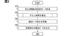
- FIG. 1 It is a figure which shows the system including the synchronization apparatus. It is a flowchart which shows an example of the synchronization method executed by a synchronization apparatus. It is a flowchart which shows the subroutine processing of FIG. It is an image diagram which shows the process of FIG.
- the synchronization device 100 of the first embodiment will be described with reference to FIGS. 1 to 4.
- the synchronization device 100 is an electronic control device mounted on the vehicle.
- the synchronization device 100 synchronizes the time between the detection data by the plurality of sensors mounted on the vehicle.
- the plurality of time-synchronized detection data are used, for example, in the self-position estimation of the vehicle.
- the synchronization device 100 is connected to the IMU 10, the camera 20, and the self-position estimation device 200 via a communication bus or the like.
- the IMU10 is an in-vehicle sensor that detects the inertial force acting on the vehicle.
- the IMU 10 is provided by, for example, a 6-axis motion sensor having a 3-axis gyro sensor and a 3-axis acceleration sensor.
- the IMU 10 can detect each angular velocity acting in the yaw direction, pitch direction, and roll direction of the vehicle by a three-axis gyro sensor. That is, the IMU 10 is a sensor capable of detecting data on the same state quantity as the image sensor 21, which will be described later, as data on the motion state of the vehicle.
- the IMU 10 detects each acceleration acting in the front-rear direction, the up-down direction, and the left-right direction of the vehicle by the three-axis acceleration sensor.
- the IMU 10 sequentially outputs the measurement results of each gyro sensor and each acceleration sensor to the synchronization device 100 as detection data (inertia data) by the IMU 10.
- IMU10 is an example of "another sensor”.
- the camera 20 is an imaging device that outputs at least one of an image data obtained by capturing a predetermined range around the vehicle at a predetermined frame rate by an image sensor 21 and an analysis result of the image data as detection data.
- the camera 20 is fixed at a predetermined position of the vehicle, for example, with the front of the vehicle as the imaging range.
- the camera 20 is attached to, for example, the upper end of the front window, the vicinity of the rearview mirror, the upper surface of the instrument panel, or the like.
- the camera 20 includes a lens unit (not shown), an image sensor 21, and a control unit 22.
- the lens unit forms an image of light from the imaging range on the light receiving surface of the image sensor 21.
- the image sensor 21 is an image sensor that captures an image in the imaging range.
- the image sensor 21 converts the light formed on the light receiving surface into an electric signal.
- the image sensor 21 is provided by a CCD sensor, a CMOS sensor, or the like.
- the image sensor 21 sequentially outputs an electric signal to the control unit 22.
- the image sensor 21 is a sensor capable of detecting an angular velocity, which is the same state amount as the state amount detected by the IMU 10, as data indicating the motion state of the vehicle by continuously capturing an image. The angular velocity is analyzed from the image by the angular velocity calculation program described later.
- the control unit 22 mainly includes a computer including a processor 23, a memory 24, an input / output interface, and a bus connecting them.
- the processor 23 is hardware for arithmetic processing.
- the processor 23 includes, for example, at least one type of CPU (Central Processing Unit), GPU (Graphics Processing Unit), RISC (Reduced Instruction Set Computer) -CPU, and the like as a core.
- CPU Central Processing Unit
- GPU Graphics Processing Unit
- RISC Reduced Instruction Set Computer
- the memory 24 non-transiently stores or stores a computer-readable program, data, or the like, for example, at least one type of non-transitional substantive storage medium (non-transitional memory, magnetic medium, optical medium, or the like). transitory tangible storage medium).
- the memory 24 stores various programs executed by the processor 23.
- the control unit 22 controls the imaging operation of the image sensor 21 including the exposure state at the time of imaging by the image sensor 21. Specifically, the control unit 22 adjusts the timing of the electronic shutter of the pixel in the image sensor 21 to control the exposure time, selects the readout line, and selects the row and column of the pixel corresponding to the selected readout line. Make a selection and get the signal. Alternatively, the control unit 22 may collectively acquire the signals of each pixel. The control unit 22 performs image processing on the electric signal output from the image sensor 21 to generate image data of the actual scene.
- control unit 22 has an angular velocity calculation function that calculates each angular velocity in the yaw direction, pitch direction, and roll direction of the vehicle in cooperation with the image processing function by executing the angular velocity calculation program.
- the control unit 22 uses visual odometry for calculating the angular velocity, for example. Specifically, the control unit 22 extracts feature points from time-series image data and calculates the angular velocity based on the amount of change in the coordinates of the feature points for each frame.
- the angular velocity calculated by the control unit 22 includes at least an angular velocity in the pitch direction (pitch rate) and an angular velocity in the roll direction (roll rate).
- the control unit 22 sequentially provides the image data and the corresponding angular velocity data to the synchronization device 100 as detection data by the camera 20.
- the self-position estimation device 200 is an electronic control device that estimates the self-position of the vehicle. Similar to the control unit 22, the self-position estimation device 200 has a configuration mainly including a computer including a processor 201, a memory 202, an input / output interface, a bus connecting these, and the like.
- the self-position estimation device 200 realizes the self-position estimation function by executing a plurality of instructions included in the self-position estimation program stored in the memory 202 by the processor 201. For example, the self-position estimation device 200 predicts the amount of movement of the vehicle by dead reckoning based on the detection data by the IMU 10.
- the self-position estimation device 200 calculates the correction amount of the lateral and front-rear positions of the vehicle by matching the detection data by the camera 20 with the feature information of the high-precision map. By combining these information, the self-position estimation device 200 estimates the current position and the traveling direction of the vehicle as self-position information.
- the estimated self-position information is used, for example, for vehicle driving control in automatic driving or advanced driving support.
- the synchronization device 100 is an electronic control device that processes detection data from a plurality of in-vehicle sensors and provides the detection data to an in-vehicle device such as an ECU.
- the synchronization device 100 mainly includes a computer including a processor 101, a memory 102, an input / output interface, a bus connecting them, and the like.
- the processor 101 is hardware for arithmetic processing.
- the processor 101 includes, for example, at least one type of CPU (Central Processing Unit), GPU (Graphics Processing Unit), RISC (Reduced Instruction Set Computer) -CPU, and the like as a core.
- the memory 102 non-transiently stores or stores a computer-readable program, data, or the like, for example, at least one type of non-transitional substantive storage medium (non-transitional memory, magnetic medium, optical medium, or the like). transitory tangible storage medium).
- the memory 102 stores various programs executed by the processor 11, such as a synchronization program described later.
- the processor 101 executes a plurality of instructions included in the synchronization program stored in the memory 102.
- the synchronization device 100 constructs a plurality of functional blocks for driving support.
- a plurality of functional blocks are constructed by causing the processor 101 to execute a plurality of instructions by a program stored in the memory 102 to support driving.
- the synchronization device 100 is constructed with functional units such as a sensor information acquisition unit 110, a shift time calculation unit 120, and a synchronization unit 130.
- the sensor information acquisition unit 110 acquires the detection data output from the IMU 10 and the camera 20. In particular, the sensor information acquisition unit 110 acquires time-series angular velocity data included in each detection data.
- the sensor information acquisition unit 110 buffers the angular velocity data output from the IMU 10 in a time series, and generates the time series data A as the time series angular velocity data by the IMU 10. Further, the sensor information acquisition unit 110 buffers the angular velocity data output from the camera 20 in a time series, and generates time-series data B as the time-series angular velocity data by the camera 20.
- Each value of the time series data A and B is associated with time information defined by a timer, a real-time clock, or the like. The time information may be set by the synchronization device 100, or may be set by the IMU 10 and the camera 20, or another ECU or the like.
- Each time series data A and B includes at least pitch rate data and roll rate data.
- the sensor information acquisition unit 110 may acquire time-series data A and B generated by the IMU 10 and the camera 20, or another ECU.
- the sensor information acquisition unit 110 generates time-series data A and B at predetermined intervals and provides the time-series data A and B to the shift time calculation unit 120.
- the shift time calculation unit 120 calculates the shift time required for matching the time series data A and the time series data B.
- matching means that the time series data A and B substantially match on the time axis.
- the shift time calculation unit 120 determines the time at which the similarity between the time series data A and B becomes maximum when either one of the time series data A or B is shifted in time from the initial time.
- the shift width is searched for as the shift time.
- the shift time calculation unit 120 uses, for example, the likelihood that the time series data A and B match each other as a parameter indicating the degree of similarity.
- the likelihood is a value indicating the probability that the time series data A and B match each other. In this case, the larger the likelihood, the larger the similarity. Therefore, the shift time calculation unit 120 searches for the shift time having the highest likelihood.
- the shift time calculation unit 120 calculates a candidate value t for the shift time for each set of the time series data A and B generated for each set of predetermined cycles.
- the shift time calculation unit 120 determines the shift time to be used for actual data synchronization from the plurality of candidate values t calculated for each set. For example, the shift time calculation unit 120 calculates the median value of the plurality of candidate values t, and sets the median value as the shift time.
- the shift time calculation unit 120 provides the calculated shift time to the synchronization unit 130.
- the synchronization unit 130 synchronizes the detection data of the camera 20 with the detection data of the IMU 10 based on the shift time. For example, the synchronization unit 130 synchronizes by delaying the detection data of the IMU 10 by a shift time based on the detection data of the camera 20. That is, the time information of the detection data of the camera 20 is not changed, and the time information of the detection data of the IMU 10 is corrected to a time delayed by the shift time.
- the synchronization unit 130 sequentially provides each synchronized detection data to the self-position estimation device 200 and the like.
- the synchronization unit 130 may be configured to output the shift time as synchronization information between the detected data.
- the self-position estimation device 200 corrects the time information of the detection data based on the shift time as a pre-process of the sensor fusion process.
- the output of the synchronization information corresponds to the correction of the time lag between the detected data by the synchronization unit 130.
- S means a plurality of steps of the flow executed by a plurality of instructions included in the program.
- the sensor information acquisition unit 110 buffers the angular velocity data included in the detection data provided by the IMU 10 and the camera 20, and generates time-series data A and B.
- the shift time calculation unit 120 determines a candidate value t for the shift time based on the generated time series data A and B.
- FIG. 3 shows the subroutine processing in S20.
- each time series data A and B are plotted with the horizontal axis representing time and the vertical axis representing angular velocity.
- arbitrary points of interest at and i are set from the values included in the time series data A, and two points in the time series data B whose time is close to the points of interest at and i are selected (FIG. 4). See top row).
- the two points of the selected time series data B are interpolated by the interpolation line Li (see the middle part of FIG. 4).
- the two points are interpolated by a predetermined interpolation curve such as a spline curve or a cubic function curve.
- a straight line may interpolate between the two points.
- the point where the perpendicular line Lp and the interpolation line Li intersect when the perpendicular line Lp is drawn from the points of interest at and i on the time axis is set as the comparison points bt and i in the time series data B (FIG. See the bottom of 4).
- the value of the time series data B is estimated assuming that the points of interest at and i are detected at the same time.
- step S24 it is determined whether or not comparison points have been set for all the points of interest in the time series data A. If there are still points of interest for which no comparison points have been set, the process returns to step S21. On the other hand, when it is determined that the comparison points have been set for all the points of interest, the process proceeds to S25.
- the shift time at which the likelihood of the attention point group and the comparison point group is maximized is determined as the candidate value t having the largest similarity.
- a candidate value t having a likelihood value of Rmax is searched for based on the following mathematical formula (1).
- the likelihood is calculated as the magnitude of the normalized cross-correlation.
- the process proceeds to S26.
- the time-series data for setting the points of interest and the time-series data for setting the comparison points may be reversed.
- S26 it is determined whether or not the calculated number of candidate values t has reached a preset predetermined number. If it is determined that the item has not been reached, the process proceeds to S27.
- S27 the next time series data A and B, that is, the time series data A and B at different times from the time series data A and B used for calculating the candidate value t in the immediately preceding process are prepared.
- the process of S27 is executed, the process returns to S21, and a new shift time candidate value t is calculated based on the next time series data A and B.
- the process proceeds to S28.
- the median value of the plurality of candidate values t is calculated as the shift time.
- the subroutine of FIG. 3 is terminated and the process proceeds to S30 of FIG.
- the synchronization unit 130 synchronizes the detected data with each other by shifting the time of the detected data by the IMU 10 by a time difference.
- the synchronization unit 130 ends the series of processing by outputting the synchronized detection data to the self-position estimation device 200.
- S10 is an example of the "acquisition process”
- S20 is an example of the “calculation process”
- S30 is an example of the "synchronization process”.
- the synchronization device 100 calculates the shift time required for matching the time series data based on the detection data by the image sensor 21 and the time series data based on the detection data by the IMU 10 as another sensor. Then, the synchronization device 100 synchronizes the detection data by the image sensor 21 with the detection data by the IMU 10 based on the shift time. According to this, since the shift time is calculated based on the detection data of the image sensor 21, the detection data can be synchronized with each other according to the detection timing of the image sensor 21. Therefore, a synchronization device 100 capable of more accurate synchronization can be provided. Further, this enables synchronization between the sensors without using the positioning signal from the positioning satellite.
- the time series data acquired by the sensor information acquisition unit 110 includes the angular velocity data of the vehicle.
- the angular velocity can be characteristic time-series data in which the temporal fluctuation is large as compared with other parameters related to the motion state of the vehicle such as acceleration and velocity. Therefore, it becomes easy to calculate the shift time having a higher degree of similarity between the time series data A and B. Therefore, the robustness of synchronization can be further enhanced.
- the angular velocity data includes the pitch rate data of the vehicle.
- the pitch rate data can largely reflect the change in posture of the vehicle due to traveling as compared with the roll rate data and the yaw rate data. Therefore, time series data can be more volatile over time. Therefore, the robustness of synchronization can be further improved.
- pitch rate data and roll rate data are acquired as time series data.
- the roll rate data can largely reflect the change in the posture of the vehicle due to traveling as compared with the yaw rate data. Therefore, by using the roll rate data in addition to the pitch rate data to calculate the shift time, the robustness of synchronization can be further improved.
- the time of the detection data by the IMU 10 is adjusted to the detection data by the camera 20 where the delay is likely to occur. be able to.
- the similarity between the time series data A and B is calculated for each candidate value of the shift time, and the candidate value having the largest degree of similarity is adopted as the shift time. According to this, the shift time for matching the time series data A and B can be calculated from the similarity between the time series data A and B. Therefore, more accurate synchronization between the detected data becomes possible.
- the magnitude of the likelihood that the time series data A and B match each other is calculated as the similarity, and the candidate value having the highest likelihood is adopted as the shift time. According to this, the shift time for matching the time series data A and B can be calculated based on the magnitude of the matching likelihood of the time series data A and B.
- the shift time calculation unit 120 shifts the time at which the residuals between the time series data A and B are minimized, instead of the time at which the time series data A and B have the maximum likelihood of matching. Calculated as a time candidate value.
- the shift time calculation unit 120 calculates the difference value between the values of the time series data A and B for each time, and sets the parameter indicating the difference value or the sum of the values based on the difference value as the residual. Let it be a value.
- the shift time calculation unit 120 sets the comparison point group corresponding to the point cloud of interest as in the first embodiment, and then squares the difference between the data based on the following mathematical formula (2) in S25.
- the candidate value t whose sum is the minimum value S1min is searched.
- the shift time calculation unit 120 may search for a candidate value t in which the sum of the absolute values of the differences between the data is the minimum value S2min, based on the following mathematical formula (3).
- the shift time calculation unit 120 can calculate the time at which the residual between the time series data A and B is minimized as a candidate value for the shift time. In this case, the shift time calculation unit 120 can suppress the amount of calculation as compared with the case where the candidate value is calculated based on the magnitude of the likelihood.
- the synchronization device 100 acquires angular velocity data from the camera 20.
- the synchronization device 100 may be configured to generate angular velocity data by acquiring image data from the camera 20 and analyzing the image data.
- the synchronization device 100 executes inter-sensor synchronization using the pitch rate and roll rate of the vehicle, but the motion state data used for inter-sensor synchronization is not limited to this.
- the synchronization device 100 can calculate the shift time by using at least one or more time series data of the pitch rate, the roll rate, and the yaw rate. Further, the synchronization device 100 may calculate the shift time by using time series data such as acceleration or speed of the vehicle. The synchronization device 100 can use any data related to the motion state of the vehicle to calculate the shift time.
- the synchronization device 100 acquires the image data of the camera 20 having the image sensor 21 as detection data. Instead, the synchronization device 100 may acquire the point cloud data by the lidar having the image sensor 21 as the detection data.
- the synchronization device 100 synchronizes the detection data of the camera 20 with the detection data of the IMU 10.
- the synchronization device 100 may be configured to synchronize the detection data of the camera 20 with the detection data of the LIDAR or another camera. Further, the synchronization device 100 may be configured to synchronize the detection data of the LIDAR and the detection data of the IMU 10.
- the shift time calculation unit 120 calculates the median value of a plurality of shift time candidates as the shift time.
- the shift time calculation unit 120 may have a configuration in which the average value of a plurality of candidates is calculated as the shift time. Further, the shift time calculation unit 120 may vote the calculated candidate value for the vote value set at a predetermined time interval, and calculate the vote value having the largest number of voted candidate values as the shift time. Good. In this case, the shift time calculation unit 120 may set the voting destination of the candidate value to the voting value to which the candidate value corresponds when the candidate value is rounded.
- the synchronization device 100 may be a dedicated computer configured to include at least one of a digital circuit and an analog circuit as a processor.
- digital circuits include, for example, ASIC (Application Specific Integrated Circuit), FPGA (Field Programmable Gate Array), SOC (System on a Chip), PGA (Programmable Gate Array), CPLD (Complex Programmable Logic Device), and the like. Of these, at least one. Further, such a digital circuit may include a memory for storing a program.
- the synchronization device 100 may be provided by one computer, or a set of computer resources linked by a data communication device.
- a part of the functions provided by the synchronization device 100 in the above-described embodiment may be realized by another ECU.
Landscapes
- Engineering & Computer Science (AREA)
- Physics & Mathematics (AREA)
- General Physics & Mathematics (AREA)
- Theoretical Computer Science (AREA)
- Multimedia (AREA)
- Transportation (AREA)
- Mechanical Engineering (AREA)
- Mathematical Physics (AREA)
- Automation & Control Theory (AREA)
- Computer Networks & Wireless Communication (AREA)
- Signal Processing (AREA)
- Computer Vision & Pattern Recognition (AREA)
- Navigation (AREA)
- Arrangements For Transmission Of Measured Signals (AREA)
- Control Of Driving Devices And Active Controlling Of Vehicle (AREA)
- Synchronisation In Digital Transmission Systems (AREA)
Priority Applications (3)
| Application Number | Priority Date | Filing Date | Title |
|---|---|---|---|
| JP2021554125A JP7173373B2 (ja) | 2019-11-01 | 2020-09-02 | 同期装置、同期方法、および同期プログラム |
| CN202080075239.9A CN114600417B (zh) | 2019-11-01 | 2020-09-02 | 同步装置、同步方法以及存储有同步程序的存储装置 |
| US17/660,815 US12361720B2 (en) | 2019-11-01 | 2022-04-26 | Synchronization device, synchronization method, and non-transitory tangible computer readable storage medium |
Applications Claiming Priority (2)
| Application Number | Priority Date | Filing Date | Title |
|---|---|---|---|
| JP2019-200222 | 2019-11-01 | ||
| JP2019200222 | 2019-11-01 |
Related Child Applications (1)
| Application Number | Title | Priority Date | Filing Date |
|---|---|---|---|
| US17/660,815 Continuation US12361720B2 (en) | 2019-11-01 | 2022-04-26 | Synchronization device, synchronization method, and non-transitory tangible computer readable storage medium |
Publications (1)
| Publication Number | Publication Date |
|---|---|
| WO2021084896A1 true WO2021084896A1 (ja) | 2021-05-06 |
Family
ID=75715041
Family Applications (1)
| Application Number | Title | Priority Date | Filing Date |
|---|---|---|---|
| PCT/JP2020/033249 Ceased WO2021084896A1 (ja) | 2019-11-01 | 2020-09-02 | 同期装置、同期方法、および同期プログラム |
Country Status (4)
| Country | Link |
|---|---|
| US (1) | US12361720B2 (https=) |
| JP (1) | JP7173373B2 (https=) |
| CN (1) | CN114600417B (https=) |
| WO (1) | WO2021084896A1 (https=) |
Cited By (2)
| Publication number | Priority date | Publication date | Assignee | Title |
|---|---|---|---|---|
| JPWO2023176621A1 (https=) * | 2022-03-14 | 2023-09-21 | ||
| US20230406447A1 (en) * | 2022-06-16 | 2023-12-21 | Tien Hsin Industries Co., Ltd. | Bicycle derailleur system |
Families Citing this family (3)
| Publication number | Priority date | Publication date | Assignee | Title |
|---|---|---|---|---|
| JP7510842B2 (ja) * | 2020-10-21 | 2024-07-04 | 株式会社Subaru | 車両の制御装置のための周辺空間情報提供システム |
| CN113610136A (zh) * | 2021-07-30 | 2021-11-05 | 深圳元戎启行科技有限公司 | 传感器数据同步方法、装置、计算机设备和存储介质 |
| US20250290770A1 (en) * | 2024-03-14 | 2025-09-18 | Qualcomm Incorporated | Three-dimensional (3d) implicit surface reconstruction for dense high-definition (hd) maps with neural representations |
Citations (3)
| Publication number | Priority date | Publication date | Assignee | Title |
|---|---|---|---|---|
| US20040162654A1 (en) * | 2002-08-01 | 2004-08-19 | Jianbo Lu | System and method for determining a wheel departure angle for a rollover control system with respect to road roll rate and loading misalignment |
| JP2007327873A (ja) * | 2006-06-08 | 2007-12-20 | Tokyo Gas Co Ltd | 地震記録データの同期化処理方法 |
| US20180372498A1 (en) * | 2017-06-21 | 2018-12-27 | Caterpillar Inc. | System and method for determining machine state using sensor fusion |
Family Cites Families (8)
| Publication number | Priority date | Publication date | Assignee | Title |
|---|---|---|---|---|
| JP4570764B2 (ja) * | 2000-12-01 | 2010-10-27 | 本田技研工業株式会社 | 運動情報認識システム |
| JP4847824B2 (ja) | 2006-08-28 | 2011-12-28 | 株式会社国際電気通信基礎技術研究所 | 時刻同期システム |
| JP6488860B2 (ja) * | 2015-04-28 | 2019-03-27 | 株式会社豊田中央研究所 | 勾配推定装置及びプログラム |
| CN106370180B (zh) * | 2016-08-29 | 2019-06-04 | 常州市钱璟康复股份有限公司 | 基于动态时间规整算法的惯性传感器初始位置识别方法 |
| JP6710644B2 (ja) * | 2017-01-05 | 2020-06-17 | 株式会社東芝 | 動作解析装置、動作解析方法およびプログラム |
| DE112018007442B4 (de) * | 2018-05-11 | 2021-10-14 | Mitsubishi Electric Corporation | Datensynchronisationsvorrichtung, datensynchronisationsverfahren und datensynchronisationsprogramm |
| CN109186592B (zh) * | 2018-08-31 | 2022-05-20 | 腾讯科技(深圳)有限公司 | 用于视觉惯导信息融合的方法和装置以及存储介质 |
| US11181379B2 (en) * | 2019-09-12 | 2021-11-23 | Robert Bosch Gmbh | System and method for enhancing non-inertial tracking system with inertial constraints |
-
2020
- 2020-09-02 JP JP2021554125A patent/JP7173373B2/ja active Active
- 2020-09-02 CN CN202080075239.9A patent/CN114600417B/zh active Active
- 2020-09-02 WO PCT/JP2020/033249 patent/WO2021084896A1/ja not_active Ceased
-
2022
- 2022-04-26 US US17/660,815 patent/US12361720B2/en active Active
Patent Citations (3)
| Publication number | Priority date | Publication date | Assignee | Title |
|---|---|---|---|---|
| US20040162654A1 (en) * | 2002-08-01 | 2004-08-19 | Jianbo Lu | System and method for determining a wheel departure angle for a rollover control system with respect to road roll rate and loading misalignment |
| JP2007327873A (ja) * | 2006-06-08 | 2007-12-20 | Tokyo Gas Co Ltd | 地震記録データの同期化処理方法 |
| US20180372498A1 (en) * | 2017-06-21 | 2018-12-27 | Caterpillar Inc. | System and method for determining machine state using sensor fusion |
Non-Patent Citations (1)
| Title |
|---|
| OISHI, YOHEI ET AL.: "Sensor Fusion Algorithm with Radar and Camera for Fast Target Recognition Using HOG and Machine Learning", IEICE TECHNICAL REPORT, vol. 115, no. 517, 17 March 2016 (2016-03-17), pages 25 - 30 * |
Cited By (4)
| Publication number | Priority date | Publication date | Assignee | Title |
|---|---|---|---|---|
| JPWO2023176621A1 (https=) * | 2022-03-14 | 2023-09-21 | ||
| WO2023176621A1 (ja) * | 2022-03-14 | 2023-09-21 | パイオニア株式会社 | 推定装置、システム、推定方法、およびプログラム |
| US20230406447A1 (en) * | 2022-06-16 | 2023-12-21 | Tien Hsin Industries Co., Ltd. | Bicycle derailleur system |
| US11952080B2 (en) * | 2022-06-16 | 2024-04-09 | Tien Hsin Industries Co., Ltd. | Bicycle derailleur system |
Also Published As
| Publication number | Publication date |
|---|---|
| US20220254165A1 (en) | 2022-08-11 |
| CN114600417A (zh) | 2022-06-07 |
| CN114600417B (zh) | 2024-04-26 |
| JPWO2021084896A1 (https=) | 2021-05-06 |
| US12361720B2 (en) | 2025-07-15 |
| JP7173373B2 (ja) | 2022-11-16 |
Similar Documents
| Publication | Publication Date | Title |
|---|---|---|
| JP7173373B2 (ja) | 同期装置、同期方法、および同期プログラム | |
| US11181379B2 (en) | System and method for enhancing non-inertial tracking system with inertial constraints | |
| CN108139204B (zh) | 信息处理装置、位置和/或姿态的估计方法及记录介质 | |
| EP2973476B1 (en) | Systems and methods for stereo imaging with camera arrays | |
| US20160165157A1 (en) | Stereo assist with rolling shutters | |
| US20180075614A1 (en) | Method of Depth Estimation Using a Camera and Inertial Sensor | |
| US11509813B2 (en) | Image processing device | |
| JP6594180B2 (ja) | 撮像装置、撮像装置の制御方法及びプログラム | |
| JP2016193720A (ja) | 水平速度の推定のために瞬間的な回転が補償された垂直視ビデオカメラを備えたドローン | |
| US10623644B2 (en) | Image pick-up apparatus and control method thereof | |
| JP2014503408A (ja) | ステレオセンサシステムにおける、画像検出に適した2つのセンサの画像情報の処理方法および装置 | |
| JP6306735B2 (ja) | ステレオカメラ装置及びステレオカメラ装置を備える車両 | |
| JP2017028655A (ja) | 追跡システム、追跡方法および追跡プログラム | |
| US20140286537A1 (en) | Measurement device, measurement method, and computer program product | |
| US11310423B2 (en) | Image capturing method and image capturing apparatus | |
| JP7140291B2 (ja) | 同期装置、同期方法、同期プログラム | |
| WO2023067867A1 (ja) | 車載制御装置、および、3次元情報取得方法 | |
| JP2020201587A (ja) | 撮像装置、車両及びプログラム | |
| EP4235574A1 (en) | Measuring device, moving device, measuring method, and storage medium | |
| US11282223B2 (en) | Signal processing apparatus, signal processing method, and imaging apparatus | |
| US20250111678A1 (en) | Estimation device and estimation method | |
| JP2019066327A (ja) | 車両の周辺監視装置および周辺監視方法 | |
| KR101636233B1 (ko) | 카메라 촬영영상 안정화장치 및 그 방법 | |
| WO2024150626A1 (ja) | 情報処理装置および方法 | |
| JP6602089B2 (ja) | 画像処理装置及びその制御方法 |
Legal Events
| Date | Code | Title | Description |
|---|---|---|---|
| 121 | Ep: the epo has been informed by wipo that ep was designated in this application |
Ref document number: 20881918 Country of ref document: EP Kind code of ref document: A1 |
|
| ENP | Entry into the national phase |
Ref document number: 2021554125 Country of ref document: JP Kind code of ref document: A |
|
| NENP | Non-entry into the national phase |
Ref country code: DE |
|
| 122 | Ep: pct application non-entry in european phase |
Ref document number: 20881918 Country of ref document: EP Kind code of ref document: A1 |