WO2021070809A1 - アクチュエータおよびその製造方法、駆動装置および電子機器 - Google Patents
アクチュエータおよびその製造方法、駆動装置および電子機器 Download PDFInfo
- Publication number
- WO2021070809A1 WO2021070809A1 PCT/JP2020/037846 JP2020037846W WO2021070809A1 WO 2021070809 A1 WO2021070809 A1 WO 2021070809A1 JP 2020037846 W JP2020037846 W JP 2020037846W WO 2021070809 A1 WO2021070809 A1 WO 2021070809A1
- Authority
- WO
- WIPO (PCT)
- Prior art keywords
- electrode
- actuator
- elastomer layer
- take
- adhesive layer
- Prior art date
- Legal status (The legal status is an assumption and is not a legal conclusion. Google has not performed a legal analysis and makes no representation as to the accuracy of the status listed.)
- Ceased
Links
Images



Classifications
-
- H—ELECTRICITY
- H02—GENERATION; CONVERSION OR DISTRIBUTION OF ELECTRIC POWER
- H02N—ELECTRIC MACHINES NOT OTHERWISE PROVIDED FOR
- H02N11/00—Generators or motors not provided for elsewhere; Alleged perpetua mobilia obtained by electric or magnetic means
- H02N11/006—Motors
-
- B—PERFORMING OPERATIONS; TRANSPORTING
- B32—LAYERED PRODUCTS
- B32B—LAYERED PRODUCTS, i.e. PRODUCTS BUILT-UP OF STRATA OF FLAT OR NON-FLAT, e.g. CELLULAR OR HONEYCOMB, FORM
- B32B7/00—Layered products characterised by the relation between layers; Layered products characterised by the relative orientation of features between layers, or by the relative values of a measurable parameter between layers, i.e. products comprising layers having different physical, chemical or physicochemical properties; Layered products characterised by the interconnection of layers
- B32B7/04—Interconnection of layers
- B32B7/12—Interconnection of layers using interposed adhesives or interposed materials with bonding properties
-
- B—PERFORMING OPERATIONS; TRANSPORTING
- B32—LAYERED PRODUCTS
- B32B—LAYERED PRODUCTS, i.e. PRODUCTS BUILT-UP OF STRATA OF FLAT OR NON-FLAT, e.g. CELLULAR OR HONEYCOMB, FORM
- B32B25/00—Layered products comprising a layer of natural or synthetic rubber
- B32B25/04—Layered products comprising a layer of natural or synthetic rubber comprising rubber as the main or only constituent of a layer, which is next to another layer of the same or of a different material
- B32B25/042—Layered products comprising a layer of natural or synthetic rubber comprising rubber as the main or only constituent of a layer, which is next to another layer of the same or of a different material of natural rubber or synthetic rubber
-
- B—PERFORMING OPERATIONS; TRANSPORTING
- B06—GENERATING OR TRANSMITTING MECHANICAL VIBRATIONS IN GENERAL
- B06B—METHODS OR APPARATUS FOR GENERATING OR TRANSMITTING MECHANICAL VIBRATIONS OF INFRASONIC, SONIC, OR ULTRASONIC FREQUENCY, e.g. FOR PERFORMING MECHANICAL WORK IN GENERAL
- B06B1/00—Methods or apparatus for generating mechanical vibrations of infrasonic, sonic, or ultrasonic frequency
- B06B1/02—Methods or apparatus for generating mechanical vibrations of infrasonic, sonic, or ultrasonic frequency making use of electrical energy
-
- B—PERFORMING OPERATIONS; TRANSPORTING
- B32—LAYERED PRODUCTS
- B32B—LAYERED PRODUCTS, i.e. PRODUCTS BUILT-UP OF STRATA OF FLAT OR NON-FLAT, e.g. CELLULAR OR HONEYCOMB, FORM
- B32B25/00—Layered products comprising a layer of natural or synthetic rubber
-
- B—PERFORMING OPERATIONS; TRANSPORTING
- B32—LAYERED PRODUCTS
- B32B—LAYERED PRODUCTS, i.e. PRODUCTS BUILT-UP OF STRATA OF FLAT OR NON-FLAT, e.g. CELLULAR OR HONEYCOMB, FORM
- B32B25/00—Layered products comprising a layer of natural or synthetic rubber
- B32B25/04—Layered products comprising a layer of natural or synthetic rubber comprising rubber as the main or only constituent of a layer, which is next to another layer of the same or of a different material
-
- B—PERFORMING OPERATIONS; TRANSPORTING
- B32—LAYERED PRODUCTS
- B32B—LAYERED PRODUCTS, i.e. PRODUCTS BUILT-UP OF STRATA OF FLAT OR NON-FLAT, e.g. CELLULAR OR HONEYCOMB, FORM
- B32B25/00—Layered products comprising a layer of natural or synthetic rubber
- B32B25/20—Layered products comprising a layer of natural or synthetic rubber comprising silicone rubber
-
- B—PERFORMING OPERATIONS; TRANSPORTING
- B32—LAYERED PRODUCTS
- B32B—LAYERED PRODUCTS, i.e. PRODUCTS BUILT-UP OF STRATA OF FLAT OR NON-FLAT, e.g. CELLULAR OR HONEYCOMB, FORM
- B32B3/00—Layered products comprising a layer with external or internal discontinuities or unevennesses, or a layer of non-planar shape; Layered products comprising a layer having particular features of form
- B32B3/02—Layered products comprising a layer with external or internal discontinuities or unevennesses, or a layer of non-planar shape; Layered products comprising a layer having particular features of form characterised by features of form at particular places, e.g. in edge regions
- B32B3/08—Layered products comprising a layer with external or internal discontinuities or unevennesses, or a layer of non-planar shape; Layered products comprising a layer having particular features of form characterised by features of form at particular places, e.g. in edge regions characterised by added members at particular parts
-
- B—PERFORMING OPERATIONS; TRANSPORTING
- B32—LAYERED PRODUCTS
- B32B—LAYERED PRODUCTS, i.e. PRODUCTS BUILT-UP OF STRATA OF FLAT OR NON-FLAT, e.g. CELLULAR OR HONEYCOMB, FORM
- B32B3/00—Layered products comprising a layer with external or internal discontinuities or unevennesses, or a layer of non-planar shape; Layered products comprising a layer having particular features of form
- B32B3/26—Layered products comprising a layer with external or internal discontinuities or unevennesses, or a layer of non-planar shape; Layered products comprising a layer having particular features of form characterised by a particular shape of the outline of the cross-section of a continuous layer; characterised by a layer with cavities or internal voids ; characterised by an apertured layer
- B32B3/266—Layered products comprising a layer with external or internal discontinuities or unevennesses, or a layer of non-planar shape; Layered products comprising a layer having particular features of form characterised by a particular shape of the outline of the cross-section of a continuous layer; characterised by a layer with cavities or internal voids ; characterised by an apertured layer characterised by an apertured layer, the apertures going through the whole thickness of the layer, e.g. expanded metal, perforated layer, slit layer regular cells B32B3/12
-
- B—PERFORMING OPERATIONS; TRANSPORTING
- B32—LAYERED PRODUCTS
- B32B—LAYERED PRODUCTS, i.e. PRODUCTS BUILT-UP OF STRATA OF FLAT OR NON-FLAT, e.g. CELLULAR OR HONEYCOMB, FORM
- B32B7/00—Layered products characterised by the relation between layers; Layered products characterised by the relative orientation of features between layers, or by the relative values of a measurable parameter between layers, i.e. products comprising layers having different physical, chemical or physicochemical properties; Layered products characterised by the interconnection of layers
- B32B7/02—Physical, chemical or physicochemical properties
- B32B7/022—Mechanical properties
-
- H—ELECTRICITY
- H02—GENERATION; CONVERSION OR DISTRIBUTION OF ELECTRIC POWER
- H02N—ELECTRIC MACHINES NOT OTHERWISE PROVIDED FOR
- H02N11/00—Generators or motors not provided for elsewhere; Alleged perpetua mobilia obtained by electric or magnetic means
-
- H—ELECTRICITY
- H10—SEMICONDUCTOR DEVICES; ELECTRIC SOLID-STATE DEVICES NOT OTHERWISE PROVIDED FOR
- H10N—ELECTRIC SOLID-STATE DEVICES NOT OTHERWISE PROVIDED FOR
- H10N30/00—Piezoelectric or electrostrictive devices
- H10N30/01—Manufacture or treatment
- H10N30/05—Manufacture of multilayered piezoelectric or electrostrictive devices, or parts thereof, e.g. by stacking piezoelectric bodies and electrodes
-
- H—ELECTRICITY
- H10—SEMICONDUCTOR DEVICES; ELECTRIC SOLID-STATE DEVICES NOT OTHERWISE PROVIDED FOR
- H10N—ELECTRIC SOLID-STATE DEVICES NOT OTHERWISE PROVIDED FOR
- H10N30/00—Piezoelectric or electrostrictive devices
- H10N30/01—Manufacture or treatment
- H10N30/06—Forming electrodes or interconnections, e.g. leads or terminals
- H10N30/067—Forming single-layered electrodes of multilayered piezoelectric or electrostrictive parts
-
- H—ELECTRICITY
- H10—SEMICONDUCTOR DEVICES; ELECTRIC SOLID-STATE DEVICES NOT OTHERWISE PROVIDED FOR
- H10N—ELECTRIC SOLID-STATE DEVICES NOT OTHERWISE PROVIDED FOR
- H10N30/00—Piezoelectric or electrostrictive devices
- H10N30/20—Piezoelectric or electrostrictive devices with electrical input and mechanical output, e.g. functioning as actuators or vibrators
-
- H—ELECTRICITY
- H10—SEMICONDUCTOR DEVICES; ELECTRIC SOLID-STATE DEVICES NOT OTHERWISE PROVIDED FOR
- H10N—ELECTRIC SOLID-STATE DEVICES NOT OTHERWISE PROVIDED FOR
- H10N30/00—Piezoelectric or electrostrictive devices
- H10N30/20—Piezoelectric or electrostrictive devices with electrical input and mechanical output, e.g. functioning as actuators or vibrators
- H10N30/206—Piezoelectric or electrostrictive devices with electrical input and mechanical output, e.g. functioning as actuators or vibrators using only longitudinal or thickness displacement, e.g. d33 or d31 type devices
-
- H—ELECTRICITY
- H10—SEMICONDUCTOR DEVICES; ELECTRIC SOLID-STATE DEVICES NOT OTHERWISE PROVIDED FOR
- H10N—ELECTRIC SOLID-STATE DEVICES NOT OTHERWISE PROVIDED FOR
- H10N30/00—Piezoelectric or electrostrictive devices
- H10N30/50—Piezoelectric or electrostrictive devices having a stacked or multilayer structure
-
- H—ELECTRICITY
- H10—SEMICONDUCTOR DEVICES; ELECTRIC SOLID-STATE DEVICES NOT OTHERWISE PROVIDED FOR
- H10N—ELECTRIC SOLID-STATE DEVICES NOT OTHERWISE PROVIDED FOR
- H10N30/00—Piezoelectric or electrostrictive devices
- H10N30/80—Constructional details
- H10N30/87—Electrodes or interconnections, e.g. leads or terminals
-
- H—ELECTRICITY
- H10—SEMICONDUCTOR DEVICES; ELECTRIC SOLID-STATE DEVICES NOT OTHERWISE PROVIDED FOR
- H10N—ELECTRIC SOLID-STATE DEVICES NOT OTHERWISE PROVIDED FOR
- H10N30/00—Piezoelectric or electrostrictive devices
- H10N30/80—Constructional details
- H10N30/87—Electrodes or interconnections, e.g. leads or terminals
- H10N30/871—Single-layered electrodes of multilayer piezoelectric or electrostrictive devices, e.g. internal electrodes
-
- B—PERFORMING OPERATIONS; TRANSPORTING
- B32—LAYERED PRODUCTS
- B32B—LAYERED PRODUCTS, i.e. PRODUCTS BUILT-UP OF STRATA OF FLAT OR NON-FLAT, e.g. CELLULAR OR HONEYCOMB, FORM
- B32B2250/00—Layers arrangement
- B32B2250/42—Alternating layers, e.g. ABAB(C), AABBAABB(C)
-
- B—PERFORMING OPERATIONS; TRANSPORTING
- B32—LAYERED PRODUCTS
- B32B—LAYERED PRODUCTS, i.e. PRODUCTS BUILT-UP OF STRATA OF FLAT OR NON-FLAT, e.g. CELLULAR OR HONEYCOMB, FORM
- B32B2250/00—Layers arrangement
- B32B2250/44—Number of layers variable across the laminate
-
- B—PERFORMING OPERATIONS; TRANSPORTING
- B32—LAYERED PRODUCTS
- B32B—LAYERED PRODUCTS, i.e. PRODUCTS BUILT-UP OF STRATA OF FLAT OR NON-FLAT, e.g. CELLULAR OR HONEYCOMB, FORM
- B32B2307/00—Properties of the layers or laminate
- B32B2307/20—Properties of the layers or laminate having particular electrical or magnetic properties, e.g. piezoelectric
- B32B2307/202—Conductive
-
- B—PERFORMING OPERATIONS; TRANSPORTING
- B32—LAYERED PRODUCTS
- B32B—LAYERED PRODUCTS, i.e. PRODUCTS BUILT-UP OF STRATA OF FLAT OR NON-FLAT, e.g. CELLULAR OR HONEYCOMB, FORM
- B32B2307/00—Properties of the layers or laminate
- B32B2307/20—Properties of the layers or laminate having particular electrical or magnetic properties, e.g. piezoelectric
- B32B2307/204—Di-electric
-
- B—PERFORMING OPERATIONS; TRANSPORTING
- B32—LAYERED PRODUCTS
- B32B—LAYERED PRODUCTS, i.e. PRODUCTS BUILT-UP OF STRATA OF FLAT OR NON-FLAT, e.g. CELLULAR OR HONEYCOMB, FORM
- B32B2307/00—Properties of the layers or laminate
- B32B2307/20—Properties of the layers or laminate having particular electrical or magnetic properties, e.g. piezoelectric
- B32B2307/206—Insulating
-
- B—PERFORMING OPERATIONS; TRANSPORTING
- B32—LAYERED PRODUCTS
- B32B—LAYERED PRODUCTS, i.e. PRODUCTS BUILT-UP OF STRATA OF FLAT OR NON-FLAT, e.g. CELLULAR OR HONEYCOMB, FORM
- B32B2307/00—Properties of the layers or laminate
- B32B2307/50—Properties of the layers or laminate having particular mechanical properties
- B32B2307/51—Elastic
-
- B—PERFORMING OPERATIONS; TRANSPORTING
- B32—LAYERED PRODUCTS
- B32B—LAYERED PRODUCTS, i.e. PRODUCTS BUILT-UP OF STRATA OF FLAT OR NON-FLAT, e.g. CELLULAR OR HONEYCOMB, FORM
- B32B2307/00—Properties of the layers or laminate
- B32B2307/70—Other properties
- B32B2307/732—Dimensional properties
-
- B—PERFORMING OPERATIONS; TRANSPORTING
- B32—LAYERED PRODUCTS
- B32B—LAYERED PRODUCTS, i.e. PRODUCTS BUILT-UP OF STRATA OF FLAT OR NON-FLAT, e.g. CELLULAR OR HONEYCOMB, FORM
- B32B2457/00—Electrical equipment
-
- H—ELECTRICITY
- H10—SEMICONDUCTOR DEVICES; ELECTRIC SOLID-STATE DEVICES NOT OTHERWISE PROVIDED FOR
- H10N—ELECTRIC SOLID-STATE DEVICES NOT OTHERWISE PROVIDED FOR
- H10N30/00—Piezoelectric or electrostrictive devices
- H10N30/80—Constructional details
- H10N30/85—Piezoelectric or electrostrictive active materials
- H10N30/857—Macromolecular compositions
Definitions
- the present disclosure relates to actuators and their manufacturing methods, drives and electronic devices.
- polymer actuators that convert electrical energy into mechanical energy are widely known.
- As one of the polymer actuators there is a laminated type actuator in which electrodes and elastomer layers are alternately laminated (see, for example, Patent Document 1).
- the laminated actuator has a low dielectric strength.
- An object of the present disclosure is to provide an actuator capable of improving the adhesion between the electrode and the elastomer layer, a method for manufacturing the actuator, a driving device, and an electronic device.
- the first disclosure is Multiple laminated electrode sheets and With an adhesive layer provided between adjacent electrode sheets,
- the electrode sheet is With an elastomer layer With an electrode provided on the elastomer layer,
- the plurality of electrode sheets are laminated so that the elastomer layers and the electrodes are alternately positioned.
- the adhesive layer is an actuator that is thinner than the electrodes.
- the second disclosure is a drive device including the actuator of the first disclosure.
- the third disclosure is an electronic device including the actuator of the first disclosure.
- the fourth disclosure is Forming an electrode on the first elastomer layer and Forming an adhesive layer on the electrodes and By adhering the second elastomer layer to the first elastomer layer by the adhesive layer, Including
- the adhesive layer is a method for manufacturing an actuator having a thickness thinner than that of an electrode.
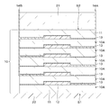
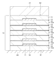
- FIG. 1 is a cross-sectional view showing an example of the configuration of the actuator according to the first embodiment of the present disclosure.
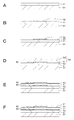
- 2A, 2B, 2C, 2D, 2E, and 2F are process diagrams for explaining an example of an actuator manufacturing method according to the first embodiment of the present disclosure, respectively.
- 3A and 3B are process diagrams for explaining an example of an actuator manufacturing method according to the first embodiment of the present disclosure, respectively.
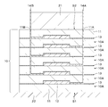
- FIG. 4 is a cross-sectional view showing an example of the configuration of the actuator according to the modified example of the first embodiment of the present disclosure.
- FIG. 5 is a cross-sectional view showing an example of the configuration of the actuator according to the modified example of the first embodiment of the present disclosure.
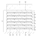
- FIG. 6 is a cross-sectional view showing an example of the configuration of the actuator according to the modified example of the first embodiment of the present disclosure.
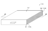
- FIG. 7 is a perspective view showing an example of the appearance of the actuator according to the second embodiment of the present disclosure.
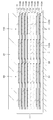
- FIG. 8 is a cross-sectional view taken along the line VIII-VIII of FIG.
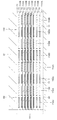
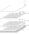
- FIG. 9 is an exploded perspective view showing an example of the configuration of the actuator according to the second embodiment of the present disclosure.
- FIG. 10 is a cross-sectional view showing an example of the configuration of the actuator according to the modified example of the second embodiment of the present disclosure.
- FIG. 11 is an exploded perspective view showing an example of the configuration of the actuator according to the modified example of the second embodiment of the present disclosure.
- FIG. 12 is a cross-sectional view showing an example of the configuration of a photographing apparatus as an application example.
- FIG. 13A is a plan view showing an example of the configuration of a lens and a holder for holding the lens.
- FIG. 13B is a cross-sectional view taken along the line XIIIB-XIIIB of FIG. 13A.
- FIG. 14 is an enlarged cross-sectional view showing the region R of FIG. 13B.
- FIG. 15 is a cross-sectional view showing an example of the configuration of a display device as an application example.
- FIG. 16 is a cross-sectional view showing an example of the configuration of a multi-point tactile display as an application example.
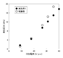
- FIG. 17 is a graph showing the relationship between the applied electric field and the generated stress of the dielectric elastomer actuator of Example 1.
- the actuator 10 is a laminated dielectric elastomer actuator (Dielectric Elastomer Actuator: DEA).
- the actuator 10 has a rectangular sheet shape.
- the actuator 10 has a first main surface S1 and a second main surface S2 that face each other.
- the sheet is defined to include a film.
- the actuator 10 includes a plurality of electrode sheets 10A, an adhesive layer 13, a take-out electrode 14A, and a take-out electrode 14B.
- the take-out electrodes 14A and 14B may or may not be provided as needed.
- the actuator 10 is configured to expand and contract in the in-plane direction of the actuator 10 by applying a voltage. That is, the actuator 10 is configured to be displaceable in the thickness direction of the actuator 10.
- the actuator 10 can be applied to various driving devices or electronic devices.
- the actuator 10 is fixed on the base material 22 of the driving device or the electronic device.
- a driven body 21 of a driving device or an electronic device is fixed on the actuator 10.
- the actuator 10 and the base material 22 are bonded by an adhesive (not shown), and the actuator 10 and the driven body 21 are bonded by an adhesive (not shown).
- pressure sensitive adhesion is defined as a type of adhesion.
- the drive device to which the actuator 10 can be applied include a lens drive device, a camera shake correction device, and a vibration device (tactile display, vibrator, acoustic converter (speaker, etc.)), but are not limited thereto. Absent.
- Specific examples of the electronic device to which the actuator 10 can be applied include a personal computer, a mobile device, a mobile phone, a tablet computer, a display device, a photographing device, an audio device, a game device, an industrial device, a robot, and the like. It is not limited to these.
- the plurality of electrode sheets 10A are laminated to form a laminated body.
- the electrode sheet 10A includes an elastomer layer 11 and an electrode 12 provided on the elastomer layer 11.
- the plurality of electrode sheets 10A are laminated so that the elastomer layers 11 and the electrodes 12 are alternately positioned. From the viewpoint of insulation, it is preferable that the first and second main surfaces S1 and S2 of the actuator 10 are covered with the elastomer layer 11.
- the elastomer layer 11 has elasticity in the in-plane direction of the actuator 10. Each elastomer layer 11 is sandwiched between a set of electrodes 12.
- the elastomer layer 11 is a dielectric elastomer layer and is a sheet having a rectangular shape.
- the elastomer layer 11 contains, for example, an insulating elastomer as an insulating elastic material.
- the insulating elastomer includes, for example, acrylic rubber, silicone rubber, ethylene-propylene-diene ternary copolymer (EPDM), natural rubber (NR), butyl rubber (IIR), isoprene rubber (IR), and acrylonitrile-butadiene copolymer rubber. (NBR), hydride acrylic nitrile-butadiene copolymer rubber (H-NBR), hydrin-based rubber, chloroprene rubber (CR), fluororubber, urethane rubber and the like.
- the elastomer layer 11 may contain an additive if necessary.
- the additive is, for example, at least one of a cross-linking agent, a plasticizer, an anti-aging agent, a surfactant, a viscosity modifier, a reinforcing agent, a coloring agent, and the like.
- the electrode 12 has elasticity in the in-plane direction of the actuator 10. As a result, the electrode 12 can expand and contract according to the expansion and contraction of the elastomer layer 11.
- the elastomer layer 11 is sandwiched between the electrodes 12 adjacent to each other in the thickness direction of the actuator 10.
- the electrodes 12 included in each electrode sheet 10A overlap each other in the thickness direction of the actuator 10. Examples of the shape of the electrode 12 include a polygonal shape such as a rectangular shape, a circular shape, an elliptical shape, and the like.
- the ratio (D2 / D1) of the thickness D2 of the electrode 12 to the thickness D1 of the elastomer layer 11 is preferably 1/2 or less, more preferably 1/10 or more and 1/2 or less.
- the ratio (D2 / D1) exceeds 1/2, the displacement amount is significantly reduced due to the influence of the rigidity of the electrode 12.
- the ratio (D2 / D1) is less than 1/10, the resistance of the electrode 12 increases and the responsiveness deteriorates.
- the electrode 12 contains a conductive material.
- the conductive material is, for example, at least one of a conductive filler and a conductive polymer.
- Examples of the shape of the conductive filler include a spherical shape, an ellipsoidal shape, a needle shape, a plate shape, a scale shape, a tube shape, a wire shape, a rod shape (rod shape), a fibrous shape, an indefinite shape, and the like. It is not limited to. It should be noted that only one type of conductive filler may be used, or two or more types of conductive fillers may be used in combination.
- the conductive filler contains, for example, at least one of a carbon-based filler, a metal-based filler, a metal oxide-based filler, and a metal coating-based filler.
- the metal is defined as including a semimetal.
- the carbon-based filler is, for example, carbon black (for example, Ketjen black, acetylene black, etc.), porous carbon, carbon fiber (for example, PAN-based, pitch-based, etc.), carbon nanofiber, fullerene, graphene, vapor-grown carbon fiber (VGCF). ), Carbon nanotubes (eg SWCNT, MWCNT, etc.), carbon microcoils and carbon nanohorns.
- Metallic fillers include, for example, copper, silver, gold, platinum, palladium, nickel, tin, cobalt, rhodium, iridium, iron, ruthenium, osmium, manganese, molybdenum, tungsten, niobium, tantalum, titanium, bismuth, antimony and lead. Includes at least one of.
- Metal oxide-based fillers include, for example, indium tin oxide (ITO), zinc oxide, indium oxide, antimony-added tin oxide, fluorine-added tin oxide, aluminum-added zinc oxide, gallium-added zinc oxide, silicon-added zinc oxide, and zinc oxide.
- ITO indium tin oxide
- zinc oxide zinc oxide
- indium oxide antimony-added tin oxide
- fluorine-added tin oxide aluminum-added zinc oxide
- gallium-added zinc oxide gallium-added zinc oxide
- silicon-added zinc oxide silicon-added zinc oxide
- zinc oxide -Includes tin oxide, indium oxide-tin oxide or zinc oxide-indium oxide-magnesium oxide.
- the metal coating type filler is a base filler coated with metal.
- the base filler is, for example, mica, glass beads, glass fiber, carbon fiber, calcium carbonate, zinc oxide or titanium oxide.
- the metal coating the base filler contains, for example, at least one of Ni and Al.
- the conductive polymer contains, for example, at least one of polyethylene dioxythiophene / polystyrene sulfonic acid (PEDOT / PSS), polyaniline, polyacetylene and polypyrrole.
- PEDOT / PSS polyethylene dioxythiophene / polystyrene sulfonic acid
- polyaniline polyaniline
- polyacetylene polypyrrole
- the electrode 12 may further contain at least one of a binder, gel, suspension and oil, if desired.
- the binder has elasticity.
- the binder is preferably an elastomer. Examples of the elastomer include those similar to those of the elastomer layer 11.
- the electrode 12 may further contain an additive if necessary.
- the additive include those similar to those of the elastomer layer 11.
- the electrode 12 may contain a composite material (composite material).
- the composite material is, for example, a composite material of at least one of a conductive polymer and a conductive filler and an elastomer, a composite material of an elastic ion conductive material and an electric field material, and at least a conductive polymer and a conductive filler.
- Composite material of 1 type and polymer suspension (acrylic emulsion, etc.), composite material of at least 1 type of conductive polymer and conductive filler and block copolyma, and composite of polymer gel and ionic conductor Contains at least one of the materials.
- the adhesive layer 13 is provided between the adjacent electrode sheets 10A, and the adjacent electrode sheets 10A are bonded together.
- the adhesive layer 13 adheres the elastomer layer 11 of the adjacent electrode sheet 10A to the electrode 12.
- the adhesive layer 13 preferably covers the electrode 12, and covers the entire main surface of the elastomer layer 11 provided with the electrode 12. More preferred.
- the adhesive layer 13 is thinner than the electrode 12. As a result, the drive voltage of the actuator 10 can be reduced.
- the adhesive layer 13 preferably contains a silicone-based adhesive.
- the electrode 12 and the adhesive layer 13 contain the same material. It is more preferable that the elastomer layer 11, the adhesive layer 13 and the electrode 12 contain the same kind of material. In this case, the adhesive contained in the adhesive layer 13 and the binder contained in the electrode 12 may be made of the same type of material.
- the same type of material is preferably a silicone-based material.
- the take-out electrodes 14A and 14B preferably have elasticity. As a result, the take-out electrodes 14A and 14B can expand and contract according to the expansion and contraction of the actuator 10. Therefore, the take-out electrodes 14A and 14B can suppress the breakage of the take-out electrodes 14A and 14B and the peeling from the elastomer layer 11 due to the expansion and contraction of the actuator 10, respectively.
- the take-out electrodes 14A and 14B electrically connect the electrode 12 of the laminated electrode sheet 10A and an external voltage source (not shown).
- the take-out electrode 14A is connected to the electrode 12 of the electrode sheet 10A located at an odd number from the first main surface S1 of the actuator 10 among the plurality of laminated electrode sheets 10A.
- the take-out electrode 14B is connected to the electrode 12 of the electrode sheet 10A located even-numbered from the first main surface S1 of the actuator 10 among the plurality of laminated electrode sheets 10A.
- the take-out electrode 14A and the take-out electrode 14B are taken out from between the peripheral portions of the laminated electrode sheets 10A through between the laminated elastomer layers 11.
- the take-out electrodes 14A and 14B are taken out from different positions on the peripheral edge of the laminated electrode sheets 10A, for example, opposite positions.
- the take-out electrodes 14A and 14B contain a conductive material.
- the conductive material the same material as the electrode 12 can be exemplified.
- the take-out electrodes 14A and 14B may contain a stretchable binder, if necessary.
- the binder is preferably an elastomer. Examples of the elastomer include those similar to those of the elastomer layer 11.
- the take-out electrodes 14A and 14B have, for example, a linear shape.
- the term "upward” means the thickness direction of the actuator 10 from the first main surface S1 to the second main surface S2.
- the default state (initial state) of the actuator 10 may be a state in which a predetermined voltage is applied to the actuator 10. A voltage may not be applied to 10.
- a coating material for forming an elastomer layer is prepared by adding an elastomer to a solvent and dispersing it. If necessary, at least one of a resin material other than the elastomer and an additive may be further added to the solvent. For example, for the purpose of improving the coatability and pot life of the coating material for forming the elastomer layer on the base material (peeling base material), additives such as a surfactant, a viscosity modifier, and a dispersant may be added as necessary. Good.
- the dispersion method it is preferable to use stirring, ultrasonic dispersion, bead dispersion, kneading, homogenizer treatment and the like.
- the solvent is not particularly limited as long as it can disperse the elastomer.
- water ethanol, methyl ethyl ketone, isopropanol alcohol, acetone, anone (cyclohexanone, cyclopentanone), hydrocarbon (hexane), amide (DMF), sulfide (DMSO), butyl cellosolve, butyl triglycol, propylene glycol monomethyl ether, propylene.
- Glycol monoethyl ether ethylene glycol monoethyl ether, ethylene glycol monopropyl ether, ethylene glycol monoisopropyl ether, diethylene glycol monobutyl ether, diethylene glycol monoethyl ether, diethylene glycol monomethyl ether, diethylene glycol diethyl ether, dipropylene glycol monomethyl ether, tripropylene glycol monomethyl
- examples thereof include ether, propylene glycol monobutyl ether, propylene glycol isopropyl ether, dipropylene glycol isopropyl ether, tripropylene glycol isopropyl ether, methyl glycol, terpineol, and butyl carbitol acetate.
- a conductive paint which is a paint for forming electrodes, is prepared by adding a conductive material to a solvent and dispersing it. If necessary, at least one of the binder and the additive may be further added to the solvent. For example, additives such as a surfactant, a viscosity modifier, and a dispersant may be added as necessary for the purpose of improving the coatability and pot life of the conductive coating material on the elastomer layers 21A and 22A.
- the conductive coating material may be a conductive ink or a conductive paste.
- the solvent is not particularly limited as long as it can disperse the conductive material. For example, the same process as the above-mentioned step of preparing the elastomer layer forming paint can be exemplified.
- the electrode-forming paint is applied onto the elastomer layer 11 to form the electrode 12.
- a method of applying the electrode forming paint (method of forming the electrode 12)
- screen printing, intaglio printing, or letterpress printing is preferable.
- the elastomer layer 11 is formed on the base material 32 with the elastomer layer forming paint, and then the elastomer layer 11 is peeled off from the base material 32 as shown in FIG. 3B to form the base material 33. Move it up. As a result, the laminated body 34 is obtained.
- the base material 33 contains a fluororesin such as polytetrafluoroethylene (PTFE). Therefore, the elastomer layer 11 can be easily peeled off from the base material 33.
- PTFE polytetrafluoroethylene
- the actuator 10 includes a plurality of laminated electrode sheets 10A and an adhesive layer 13 provided between adjacent electrode sheets.
- the adhesion between the adjacent electrode sheets 10A that is, the adhesion between the electrodes 12 and the elastomer layer 11 of the adjacent electrode sheets 10A can be improved. Therefore, the dielectric strength of the actuator 10 can be improved.
- the adhesive layer 13 is thinner than the electrode 12. As a result, the drive voltage of the actuator 10 can be reduced.
- [Modification example] (Modification example 1)
- the configuration of the take-out electrodes 14A and 14B is limited to this. It's not a thing.
- the plurality of laminated electrode sheets 10A have a hole portion 11A and a hole portion 11B extending from the second main surface S2 in the thickness direction of the actuator 10, and the take-out electrode 14A and the take-out electrode are taken out.
- the 14B may be taken out from the second main surface S2 via the hole portion 11A and the hole portion 11B, respectively.
- the electrode sheet 10A may further include a dummy electrode (dummy layer) 12A provided on the elastomer layer 11.
- the dummy electrode 12A is provided around the electrode 12.
- the dummy electrode 12A preferably has elasticity in the in-plane direction of the actuator 10. As a result, the dummy electrode 12A can expand and contract according to the expansion and contraction of the elastomer layer 11.
- the dummy electrode 12A may be made of the same material as the electrode 12, or may be made of a different material, but it is preferably made of the same material as the electrode 12.
- the dummy electrode 12A is made of the same material as the electrode 12, the electrode 12 and the dummy electrode 12A can be formed at the same time, so that the manufacturing process of the actuator 10 can be simplified.
- the dummy electrode 12A has conductivity, the electrode 12 and the dummy electrode 12A are separated from each other.
- the thickness of the dummy electrode 12A is preferably the same as or substantially the same as that of the electrode 12.
- the electrode sheet 10A By providing the electrode sheet 10A with the dummy electrode 12A as described above, it is possible to suppress the occurrence of a step around the electrode 12. Therefore, the adhesion between the adjacent electrode sheets 10A can be improved. In addition, the flatness of the elastomer layer 11 can be maintained, so that a high-quality actuator 10 can be provided.
- the electrode sheet 10A may further include an adhesive layer 16 provided between the elastomer layer 11 and the electrode 12.
- the material of the adhesive layer 16 is the same as that of the adhesive layer 13 in the first embodiment.
- the actuator 110 is a laminated dielectric elastomer actuator (Dielectric Elastomer Actuator: DEA).
- the actuator 10 has a rectangular sheet shape.
- the actuator 110 has a first main surface S1 and a second main surface S2 that face each other.
- the actuator 110 includes a laminated body 111, a take-out electrode 114A, and a take-out electrode 114B.
- the take-out electrodes 114A and 114B may or may not be provided as needed.
- the same reference numerals are given to the same parts as those in the first embodiment, and the description thereof will be omitted.
- the take-out electrodes 114A and 114B are electrically connected to a voltage source (not shown) via wiring (not shown).
- the actuator 110 is configured to expand and contract in the in-plane direction of the actuator 110 by applying a voltage. That is, the actuator 110 is configured to be displaceable in the thickness direction of the actuator 110.
- the laminated body 111 includes a plurality of electrode sheets 110A, a plurality of electrode sheets 110B, and a plurality of adhesive layers 13.
- the plurality of electrode sheets 110A and the plurality of electrode sheets 110B are laminated so that the electrode sheets 110A and the electrode sheets 110A are alternately positioned to form the laminated body 111.
- the adhesive layer 13 is provided between the adjacent electrode sheets 110A and 110B.
- the electrode sheet 110A includes an elastomer layer 11 and a plurality of electrodes 112A provided on the elastomer layer 11.
- the electrode sheet 110B includes an elastomer layer 11 and a plurality of electrodes 112B provided on the elastomer layer 11.
- the adhesive layer 13 is not shown.
- the electrode 112A and the electrode 112B are not particularly distinguished, they are referred to as the electrode 112.
- the electrode 112A of the electrode sheet 110A and the elastomer layer 11 of the electrode sheet 110B face each other via the adhesive layer 13, and the electrode 112B of the electrode sheet 110B and the elastomer layer 11 of the electrode sheet 110A face each other via the adhesive layer 13. ing.
- Each elastomer layer 11 is sandwiched between a set of electrodes 112A and 112B. From the viewpoint of insulation, it is preferable that the first and second main surfaces S1 and S2 of the actuator 110 are covered with the elastomer layer 11.
- the electrodes 112A and 112B have elasticity in the in-plane direction of the actuator 110. As a result, the electrodes 112A and 112B can expand and contract according to the expansion and contraction of the elastomer layer 11.
- the plurality of electrodes 112A and the plurality of 112Bs are arranged in stripes, respectively.
- the electrode 112B faces the electrode 112A. That is, the electrode 112A included in each electrode sheet 110A and the electrode 112B included in each electrode sheet 110B overlap each other in the thickness direction of the actuator 10.
- the electrode 112A extends to the first long side of the elastomer layer 11.
- the electrode 112B extends to the second long side of the elastomer layer 11. As a result, the end portion of the electrode 112A is exposed from the side surface on the first long side portion of the actuator 110, and the end portion of the electrode 112B is exposed from the side surface on the second long side portion side of the actuator 110.
- the plurality of electrodes 112A are covered with an adhesive layer 13. Further, the plurality of electrodes 112B are covered with an adhesive layer 13. The adhesive layer 13 is thinner than the electrodes 112A and 112B. As a result, the drive voltage of the actuator 110 can be reduced.
- the materials of the electrodes 112A and 112B are the same as the materials of the electrodes 12 in the first embodiment.
- the take-out electrodes 114A and 114B preferably have elasticity. As a result, the take-out electrodes 114A and 114B can expand and contract according to the expansion and contraction of the actuator 110. Therefore, it is possible to prevent the take-out electrodes 114A and 114B from peeling off from the side surfaces on the first and second long sides of the actuator 110, respectively.
- the take-out electrode 114A is provided on the side surface of the actuator 110 on the first long side side.
- the take-out electrode 114A is in contact with the end of the electrode 112A exposed from the side surface of the actuator 110 on the first long side.
- the take-out electrode 114B is provided on the side surface of the actuator 110 on the second long side side.
- the take-out electrode 114B is in contact with the end of the electrode 112B exposed from the side surface of the actuator 110 on the second long side.
- the take-out electrodes 114A and 114B contain a conductive material.
- the conductive material the same material as the electrode 12 in the first embodiment can be exemplified.
- the take-out electrodes 114A and 114B may contain a binder having elasticity, if necessary.
- the binder is preferably an elastomer.
- the elastomer the same elastomer layer 11 as in the first embodiment can be exemplified.
- the actuator 110 includes a plurality of electrode sheets 110A and 110B stacked alternately, and an adhesive layer 13 provided between the adjacent electrode sheets 110A and 110B. ..
- the adhesion between the adjacent electrode sheets 110A and 110B that is, the adhesion between the electrode 112A and the electrode sheet 110B of the electrode sheet 110A and the elastomer layer 11, and the adhesion between the electrode 112B and the electrode sheet 110A of the electrode sheet 110B and the elastomer layer
- the adhesion between 11 can be improved. Therefore, the dielectric strength of the actuator 110 can be improved.
- the electrode sheet 110A may further include a plurality of dummy electrodes 112C
- the electrode sheet 110B may further include a plurality of dummy electrodes 112D.
- the dummy electrodes 112C and 112D have elasticity in the in-plane direction of the actuator 110. As a result, the dummy electrodes 112C and 112D can expand and contract according to the expansion and contraction of the elastomer layer 11.
- the dummy electrode 112C is provided in the gap between the adjacent electrodes 112A on the elastomer layer 11.
- the plurality of dummy electrodes 112C are arranged in a stripe shape on one main surface of the elastomer layer 11.
- the dummy electrode 112D is provided in the gap between the adjacent electrodes 112B on the elastomer layer 11.
- the plurality of dummy electrodes 112C are arranged in a stripe shape on one main surface of the elastomer layer 11.
- the electrode sheet 110A further includes a plurality of dummy electrodes 112C
- the electrode sheet 110B further includes a plurality of dummy electrodes 112D, so that a step is generated in the gap portion of the electrode 112A and the gap portion of the electrode 112B. Can be suppressed. Therefore, the adhesion between the adjacent electrode sheets 110A and 110B can be further improved. In addition, the flatness of the elastomer layer 11 can be improved, so that a high-quality actuator 10 can be provided.
- Modification 2 In the second embodiment described above, the case where the plurality of electrodes 112A and 112B are arranged in a stripe shape has been described, but the arrangement form of the plurality of electrodes 112A and 112B is not limited to this and is in the form of a mesh. , Lattice, dot, mianda, radial, geometric pattern, mianda, concentric (eg concentric), spiral, spider web, tree, fish bone or mesh, etc. You may.
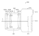
- FIG. 12 is a cross-sectional view showing an example of the configuration of the photographing apparatus 300 as an application example.
- the photographing device 300 is a so-called single-lens reflex camera, and includes a camera body 310 and a photographing lens 320 that is detachably configured with respect to the camera body.
- the photographing device 300 is an example of an electronic device.
- the camera body 310 includes an image sensor 311, a monitor 312, an electronic viewfinder 313, and the like.
- the image pickup device 311 generates an image pickup image signal by photoelectrically converting a subject light image formed by the incident light L passed through the photographing lens 320.
- the image sensor 311 is composed of, for example, a CCD image sensor or a CMOS image sensor.
- the captured image signal output from the image sensor 311 is subjected to image processing such as resolution conversion by an image processing unit (not shown) and displayed on the monitor 312 and the electronic viewfinder 313.
- image processing such as resolution conversion by an image processing unit (not shown) and displayed on the monitor 312 and the electronic viewfinder 313.
- the captured image signal is stored in a recording medium (not shown) after compression processing and recording encoding processing.
- the monitor 312 and the electronic viewfinder 313 are composed of a display device such as an organic EL (Electro-Luminescence) display or a liquid crystal display.
- a display device such as an organic EL (Electro-Luminescence) display or a liquid crystal display.
- the photographing lens 320 includes a lens optical system 321 and a lens control unit (not shown).
- the lens optical system 321 includes a plurality of lenses 321A, 321B, 321C, and a plurality of holders (support members) 322A, 322B, 322C, etc. that support these lenses 321A, 321B, 321C, respectively.
- the holder 322A includes a plurality of actuators 10 according to the first embodiment or a modification thereof, and supports the lens 321A via these actuators 10. However, the holder 322A may include the actuator 110 according to the second embodiment or its modification instead of the actuator 10 according to the first embodiment or its modification.
- FIG. 13A is a plan view showing an example of the configuration of the lens 321A and the holder 322A holding the lens 321A.
- FIG. 13B is a cross-sectional view taken along the line XIIIB-XIIIB of FIG. 13A.
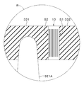
- FIG. 14 is an enlarged cross-sectional view showing the region R of FIG. 13B.
- the lens 321A is an autofocus lens.
- the holder 322A includes a lens support portion 331, a plurality of actuators 10, and a holder main body 332.
- the lens support portion 331 has a ring shape.
- the lens support portion 331 supports the lens 321A on the inner peripheral surface.
- the driven body is composed of the lens support portion 331 and the lens 321A.
- the holder body 332 has a ring shape.
- the holder body 332 supports the lens support portion 331 via a plurality of actuators 10.
- the holder body 332 is an example of a base material that supports a driven body composed of a lens support portion 331 and a lens 321A.
- the actuator 10 is an autofocus actuator.
- the actuator 10 moves the lens 321A in the optical axis direction of the incident light L.
- the second main surface S2 of the actuator 10 is fixed to the lens support portion 331.
- the first main surface S1 of the actuator 10 is fixed to the holder body 332.
- the lens 321C is a runout correction lens.
- the holder 322C includes a runout correction actuator (not shown).
- the runout correction actuator moves the lens 321C in a plane perpendicular to the optical axis of the incident light L.
- the lens control unit controls the autofocus actuator 10 and the shake correction actuator.
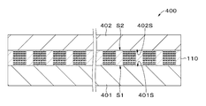
- FIG. 15 is a cross-sectional view showing an example of the configuration of the display device 400 as an application example.
- the display device 400 is a so-called flat speaker, and includes a back chassis 401, a display panel 402, an actuator 110 according to a second embodiment or a modification thereof, a control unit (not shown), and the like.
- the display device 400 may include a plurality of actuators 10 according to the first embodiment or its modification instead of the actuator 110 according to the second embodiment or its modification.
- the display device 400 is an example of an electronic device or a driving device.
- the back chassis 401 is an example of a base material that supports the actuator 110, and constitutes the back surface of the display device 400.
- the back chassis 401 is provided on the first main surface S1 of the actuator 110.
- the back chassis 401 has a support surface 401S facing the display panel 402.
- the display panel 402 is an example of a driven body driven by the actuator 110, and is, for example, an organic EL panel or a liquid crystal panel.
- the display panel 402 is provided on the second main surface S2 of the actuator 110.
- the display panel 402 has a back surface 402S facing the back chassis 401.
- the first main surface S1 of the actuator 110 is fixed to the support surface 401S.
- the second main surface S2 of the actuator 110 is fixed to the back surface 402S.
- the actuator 110 is intended to disturb the display panel 402 and emits a plane wave (sound wave).
- the control unit controls the drive of the display panel 402 and the actuator 110.
- FIG. 16 is a cross-sectional view showing an example of the configuration of the multi-point tactile display 500 as an application example.
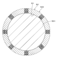
- the multi-point tactile display 500 is similar to the actuator 110 according to the second embodiment or its modification except that it has a tubular shape.
- the multi-point tactile display 500 is an example of a drive device.
- the inner peripheral surface S1 is attached to the body part 501.
- the body part 501 on which the multipoint tactile display 500 is attached include, but are not limited to, arms, legs, fingers, and the like.
- Example 1 (Elastomer layer forming step (1)) First, the addition polymerization type silicone material of the two-component mixture system is vacuum-stirred and defoamed, and then coated on a base material (PET sheet (OHP (Overhead projector) sheet)) with a film applicator, and an elastomer having a square sheet shape. A layer was formed.
- a base material PET sheet (OHP (Overhead projector) sheet)
- Electrode forming process an electrode-forming paint having the following composition was prepared and printed on the elastomer layer by a screen printing machine to form a square electrode.
- ⁇ Composition of paint for electrode formation Addition polymerization type silicone material (manufactured by Toray Dow Corning Co., Ltd., MS-1003): 4 parts by mass acetylene black (manufactured by Denka Co., Ltd., Li-100): 0.8 parts by mass Methylsiloxane (manufactured by Dow Corning Co., Ltd., OS- 10): 36 parts by mass
- the above-mentioned electrode forming step and the above-mentioned elastomer layer forming step (2) are alternately repeated, and a total of seven layers consisting of an elastomer layer / electrode / elastomer layer / electrode / elastomer layer / electrode / elastomer layer are laminated. Formed the body. As a result, the desired dielectric elastomer actuator was obtained.
- Example 1 A dielectric elastomer actuator was obtained in the same manner as in Example 1 except that the formation of the adhesion layer was omitted in the laminating step.
- the breakdown dielectric strength of the actuator of Example 1 was measured as follows. Breakdown dielectric strength is determined by measuring the applied electric field strength when the elastomer layer of an actuator with an area of 4 cm x 4 cm breaks down when the electric field strength is increased at a pace of 10 sec per 1 V / ⁇ m. did. The destruction was determined by lighting the overload lamp of the high voltage generator (HFA4321 manufactured by NF Circuit Design Block Co., Ltd.).
- Capacitance The capacitance of the actuator of Example 1 was measured to confirm that the electrodes were properly formed. The capacitance was measured under the condition of 100 Hz using an LCR meter manufactured by NF Circuit Design Block. As a result, as shown in Table 1, a capacitance of 2.54 nF was obtained. This capacitance was substantially the same as the capacitance (2.5 nF) calculated for the actuator of Example 1. From this result, it is considered that the electrodes are appropriately formed in the actuator of the first embodiment produced this time.
- the generated stress of the actuator of Example 1 was measured as follows. When the actuator was fixed to the Shimadzu universal tester Autograph AGS-X and an electric field was applied under the condition that it was stretched 1.1 times in the uniaxial direction, the force generated in the load cell was used as the generated stress.
- FIG. 17 shows the relationship between the applied electric field and the generated stress.
- FIG. 17 also shows a theoretical value calculated by assuming that the damping coefficient due to the rectangular structure is 0.6. From FIG. 17, it can be confirmed that a result substantially equal to the theoretical value is obtained. Almost no loss, etc., which seems to be caused by the interface between the elastomer layer and the electrode was observed. As the electric field strength increases, the deviation between the measured value and the theoretical value tends to increase, which is considered to be due to the effect of buckling.
- Table 1 shows the actuator configurations and evaluation results of Example 1 and Comparative Example 1.
- Table 2 shows the evaluation results of the actuator of Example 1.
- the stretching ratio means the ratio (L1 / L0) of the length per side of the actuator before stretching to L0 and the length L1 per side of the actuator after stretching.
- the present disclosure is not limited to the above-described embodiments and modifications, and various modifications based on the technical idea of the present disclosure are possible.
- the configurations, methods, processes, shapes, materials, numerical values, etc. given in the above-described embodiments and modifications are merely examples, and if necessary, different configurations, methods, processes, shapes, materials, numerical values, etc. May be used.
- the configurations, methods, processes, shapes, materials, numerical values, etc. of the above-described embodiments and modifications can be combined with each other without departing from the spirit of the present disclosure.
- the materials exemplified in the above-described embodiments and modifications can be used alone or in combination of two or more.
- the present disclosure may also adopt the following configuration.
- (1) Multiple laminated electrode sheets and It is provided with an adhesive layer provided between the adjacent electrode sheets.
- the electrode sheet is With an elastomer layer
- the electrode provided on the elastomer layer is provided.
- the plurality of electrode sheets are laminated so that the elastomer layer and the electrode are alternately positioned.
- the adhesive layer is an actuator having a thickness thinner than that of the electrode.
- the actuator according to (1) wherein the ratio (D2 / D1) of the thickness D2 of the electrode to the thickness D1 of the elastomer layer is 1/2 or less.
- the second take-out electrode is connected to the electrode of the electrode sheet located even-numbered from one main surface of the actuator among the plurality of laminated electrode sheets.
- the actuator according to any one of (1) to (7), wherein the first take-out electrode and the second take-out electrode are taken out from between the peripheral edges of the laminated electrode sheets.
- the first extraction electrode is connected to the electrode of the electrode sheet located at an odd number position with respect to one main surface of the actuator among the plurality of laminated electrode sheets.
- the second take-out electrode is connected to the electrode of the electrode sheet located even-numbered from one main surface of the actuator among the plurality of laminated electrode sheets.
- the plurality of laminated electrode sheets have a first hole portion and a second hole portion extending in the thickness direction of the actuator.
- the first take-out electrode and the second take-out electrode are described in any one of (1) to (7), which are taken out to the outside through the first hole portion and the second hole portion, respectively.
- Actuator. (10) The actuator according to any one of (1) to (9), wherein the electrode sheet further includes a dummy electrode provided on the elastomer layer.
- a drive device including the actuator according to any one of (1) to (10).
- An electronic device including the actuator according to any one of (1) to (10).
Landscapes
- Engineering & Computer Science (AREA)
- Mechanical Engineering (AREA)
- Manufacturing & Machinery (AREA)
- Laminated Bodies (AREA)
Priority Applications (3)
| Application Number | Priority Date | Filing Date | Title |
|---|---|---|---|
| JP2021551658A JPWO2021070809A1 (cg-RX-API-DMAC7.html) | 2019-10-08 | 2020-10-06 | |
| US17/754,319 US20220402245A1 (en) | 2019-10-08 | 2020-10-06 | Actuator, method for manufacturing same, drive device, and electronic device |
| CN202080069544.7A CN114514620A (zh) | 2019-10-08 | 2020-10-06 | 致动器、制造致动器的方法、驱动设备和电子设备 |
Applications Claiming Priority (2)
| Application Number | Priority Date | Filing Date | Title |
|---|---|---|---|
| JP2019-185390 | 2019-10-08 | ||
| JP2019185390 | 2019-10-08 |
Publications (1)
| Publication Number | Publication Date |
|---|---|
| WO2021070809A1 true WO2021070809A1 (ja) | 2021-04-15 |
Family
ID=75437920
Family Applications (1)
| Application Number | Title | Priority Date | Filing Date |
|---|---|---|---|
| PCT/JP2020/037846 Ceased WO2021070809A1 (ja) | 2019-10-08 | 2020-10-06 | アクチュエータおよびその製造方法、駆動装置および電子機器 |
Country Status (4)
| Country | Link |
|---|---|
| US (1) | US20220402245A1 (cg-RX-API-DMAC7.html) |
| JP (1) | JPWO2021070809A1 (cg-RX-API-DMAC7.html) |
| CN (1) | CN114514620A (cg-RX-API-DMAC7.html) |
| WO (1) | WO2021070809A1 (cg-RX-API-DMAC7.html) |
Cited By (1)
| Publication number | Priority date | Publication date | Assignee | Title |
|---|---|---|---|---|
| US20220402245A1 (en) * | 2019-10-08 | 2022-12-22 | Sony Group Corporation | Actuator, method for manufacturing same, drive device, and electronic device |
Citations (4)
| Publication number | Priority date | Publication date | Assignee | Title |
|---|---|---|---|---|
| WO2016031137A1 (ja) * | 2014-08-27 | 2016-03-03 | ソニー株式会社 | トランスデューサおよび電子機器 |
| WO2016132921A1 (ja) * | 2015-02-20 | 2016-08-25 | 信越ポリマー株式会社 | 検出センサ及びその製造方法 |
| WO2018008466A1 (ja) * | 2016-07-05 | 2018-01-11 | 信越ポリマー株式会社 | 静電容量式3次元センサ |
| WO2019065010A1 (ja) * | 2017-09-28 | 2019-04-04 | 豊田合成株式会社 | エラストマー製圧電素子、及びエラストマー製圧電素子の製造方法 |
Family Cites Families (12)
| Publication number | Priority date | Publication date | Assignee | Title |
|---|---|---|---|---|
| EP1212800B1 (en) * | 1999-07-20 | 2007-12-12 | Sri International | Electroactive polymer generators |
| JP5433991B2 (ja) * | 2008-06-24 | 2014-03-05 | 株式会社ニコン | 振動アクチュエータ、レンズ鏡筒及びカメラ |
| DE102008041657A1 (de) * | 2008-08-28 | 2010-03-04 | Robert Bosch Gmbh | Verfahren zum Verkleben von Bauteilen unter Ausbildung einer temperaturbeständigen Klebstoffschicht |
| US8222799B2 (en) * | 2008-11-05 | 2012-07-17 | Bayer Materialscience Ag | Surface deformation electroactive polymer transducers |
| US20150008798A1 (en) * | 2012-02-15 | 2015-01-08 | Bando Chemical Industries, Ltd. | Piezoelectric element, actuator element, actuator, power generating element, power generating device and flexible sheet |
| US9053617B2 (en) * | 2012-11-21 | 2015-06-09 | Novasentis, Inc. | Systems including electromechanical polymer sensors and actuators |
| EP3041059B1 (en) * | 2014-12-31 | 2019-09-11 | LG Display Co., Ltd. | Multilayer actuator and display device comprising the same |
| EP3278375B1 (en) * | 2015-03-31 | 2019-05-15 | Koninklijke Philips N.V. | Actuator or sensor device based on an electroactive polymer |
| WO2016193061A1 (de) * | 2015-05-29 | 2016-12-08 | Covestro Deutschland Ag | Ein elektromechanischer wandler bestehend aus einer zyklisch stabilen, reversibel, dehnfähigen elektrode und ein verfahren zur deren herstellung |
| JP7626525B2 (ja) * | 2016-12-29 | 2025-02-04 | ソニーグループ株式会社 | アクチュエータの製造方法 |
| CN109980080A (zh) * | 2019-03-21 | 2019-07-05 | 西安交通大学 | 一种堆栈式介电弹性体作动器制作方法 |
| JPWO2021070809A1 (cg-RX-API-DMAC7.html) * | 2019-10-08 | 2021-04-15 |
-
2020
- 2020-10-06 JP JP2021551658A patent/JPWO2021070809A1/ja active Pending
- 2020-10-06 WO PCT/JP2020/037846 patent/WO2021070809A1/ja not_active Ceased
- 2020-10-06 CN CN202080069544.7A patent/CN114514620A/zh active Pending
- 2020-10-06 US US17/754,319 patent/US20220402245A1/en not_active Abandoned
Patent Citations (4)
| Publication number | Priority date | Publication date | Assignee | Title |
|---|---|---|---|---|
| WO2016031137A1 (ja) * | 2014-08-27 | 2016-03-03 | ソニー株式会社 | トランスデューサおよび電子機器 |
| WO2016132921A1 (ja) * | 2015-02-20 | 2016-08-25 | 信越ポリマー株式会社 | 検出センサ及びその製造方法 |
| WO2018008466A1 (ja) * | 2016-07-05 | 2018-01-11 | 信越ポリマー株式会社 | 静電容量式3次元センサ |
| WO2019065010A1 (ja) * | 2017-09-28 | 2019-04-04 | 豊田合成株式会社 | エラストマー製圧電素子、及びエラストマー製圧電素子の製造方法 |
Cited By (1)
| Publication number | Priority date | Publication date | Assignee | Title |
|---|---|---|---|---|
| US20220402245A1 (en) * | 2019-10-08 | 2022-12-22 | Sony Group Corporation | Actuator, method for manufacturing same, drive device, and electronic device |
Also Published As
| Publication number | Publication date |
|---|---|
| CN114514620A (zh) | 2022-05-17 |
| JPWO2021070809A1 (cg-RX-API-DMAC7.html) | 2021-04-15 |
| US20220402245A1 (en) | 2022-12-22 |
Similar Documents
| Publication | Publication Date | Title |
|---|---|---|
| US11444555B2 (en) | Actuator including elastomer layer and elastic electrodes and method for manufacturing the same | |
| US11433425B2 (en) | Actuator, driving member, tactile sense presenting device, and driving device | |
| US20140090884A1 (en) | Elastic conductive material | |
| WO2014080470A1 (ja) | 柔軟導電部材およびそれを用いたトランスデューサ | |
| CN106664041A (zh) | 传感器和电子设备 | |
| CN104485345A (zh) | 一种柔性电极结构、其制作方法及柔性显示基板 | |
| JP4837794B1 (ja) | 駆動性能及び耐久性が改善されたトランスデューサー用電場応答性高分子 | |
| US20220402245A1 (en) | Actuator, method for manufacturing same, drive device, and electronic device | |
| JP2009232677A (ja) | エラストマートランスデューサーおよび誘電性ゴム組成物ならびに発電素子 | |
| JP4695226B1 (ja) | 駆動性能及び耐久性が改善されたアクチュエータ用電場応答性高分子 | |
| KR102381748B1 (ko) | 다층 가변 소자 및 이를 포함하는 표시 장치 | |
| JPWO2020009071A1 (ja) | 振れ補正装置、駆動装置、撮像装置および電子機器 | |
| JP7549356B2 (ja) | マルチレイヤー構造を有する静電アクチュエータ | |
| JP2009021328A (ja) | 電歪素子 | |
| CN204230306U (zh) | 一种柔性电极结构、柔性显示基板及显示装置 | |
| WO2016031137A1 (ja) | トランスデューサおよび電子機器 | |
| EP4009509B1 (en) | Actuator, drive device and electronic device | |
| KR101610794B1 (ko) | 도전성 폴리머 층을 포함한 정전기력 기반 작동기 | |
| US20240128896A1 (en) | Actuator and electronic equipment | |
| CN111625109B (zh) | 电阻式传感器及其制造方法、显示屏及触摸屏 | |
| DE102023130408A1 (de) | Schwingungsvorrichtung und vorrichtung, die diese enthält | |
| JPWO2015166700A1 (ja) | 導電パターン付絶縁基材 |
Legal Events
| Date | Code | Title | Description |
|---|---|---|---|
| 121 | Ep: the epo has been informed by wipo that ep was designated in this application |
Ref document number: 20874255 Country of ref document: EP Kind code of ref document: A1 |
|
| ENP | Entry into the national phase |
Ref document number: 2021551658 Country of ref document: JP Kind code of ref document: A |
|
| NENP | Non-entry into the national phase |
Ref country code: DE |
|
| 122 | Ep: pct application non-entry in european phase |
Ref document number: 20874255 Country of ref document: EP Kind code of ref document: A1 |