WO2021054306A1 - ソーラー発電サイトの監視・制御システム - Google Patents
ソーラー発電サイトの監視・制御システム Download PDFInfo
- Publication number
- WO2021054306A1 WO2021054306A1 PCT/JP2020/034818 JP2020034818W WO2021054306A1 WO 2021054306 A1 WO2021054306 A1 WO 2021054306A1 JP 2020034818 W JP2020034818 W JP 2020034818W WO 2021054306 A1 WO2021054306 A1 WO 2021054306A1
- Authority
- WO
- WIPO (PCT)
- Prior art keywords
- power generation
- solar
- module
- site
- monitoring
- Prior art date
- Legal status (The legal status is an assumption and is not a legal conclusion. Google has not performed a legal analysis and makes no representation as to the accuracy of the status listed.)
- Ceased
Links
Images



Classifications
-
- H—ELECTRICITY
- H02—GENERATION; CONVERSION OR DISTRIBUTION OF ELECTRIC POWER
- H02S—GENERATION OF ELECTRIC POWER BY CONVERSION OF INFRARED RADIATION, VISIBLE LIGHT OR ULTRAVIOLET LIGHT, e.g. USING PHOTOVOLTAIC [PV] MODULES
- H02S50/00—Monitoring or testing of PV systems, e.g. load balancing or fault identification
-
- H—ELECTRICITY
- H02—GENERATION; CONVERSION OR DISTRIBUTION OF ELECTRIC POWER
- H02J—ELECTRIC POWER NETWORKS; CIRCUIT ARRANGEMENTS OR SYSTEMS FOR SUPPLYING OR DISTRIBUTING ELECTRIC POWER; SYSTEMS FOR STORING ELECTRIC ENERGY
- H02J3/00—Circuit arrangements for AC mains or AC distribution networks
- H02J3/38—Arrangements for feeding a single network from two or more generators or sources in parallel; Arrangements for feeding already energised networks from additional generators or sources in parallel
- H02J3/381—Dispersed generators
-
- H—ELECTRICITY
- H02—GENERATION; CONVERSION OR DISTRIBUTION OF ELECTRIC POWER
- H02S—GENERATION OF ELECTRIC POWER BY CONVERSION OF INFRARED RADIATION, VISIBLE LIGHT OR ULTRAVIOLET LIGHT, e.g. USING PHOTOVOLTAIC [PV] MODULES
- H02S40/00—Components or accessories in combination with PV modules, not provided for in groups H02S10/00 - H02S30/00
- H02S40/30—Electrical components
-
- H—ELECTRICITY
- H02—GENERATION; CONVERSION OR DISTRIBUTION OF ELECTRIC POWER
- H02S—GENERATION OF ELECTRIC POWER BY CONVERSION OF INFRARED RADIATION, VISIBLE LIGHT OR ULTRAVIOLET LIGHT, e.g. USING PHOTOVOLTAIC [PV] MODULES
- H02S40/00—Components or accessories in combination with PV modules, not provided for in groups H02S10/00 - H02S30/00
- H02S40/30—Electrical components
- H02S40/34—Electrical components comprising specially adapted electrical connection means to be structurally associated with the PV module, e.g. junction boxes
-
- H—ELECTRICITY
- H02—GENERATION; CONVERSION OR DISTRIBUTION OF ELECTRIC POWER
- H02J—ELECTRIC POWER NETWORKS; CIRCUIT ARRANGEMENTS OR SYSTEMS FOR SUPPLYING OR DISTRIBUTING ELECTRIC POWER; SYSTEMS FOR STORING ELECTRIC ENERGY
- H02J2101/00—Supply or distribution of decentralised, dispersed or local electric power generation
- H02J2101/20—Dispersed power generation using renewable energy sources
- H02J2101/22—Solar energy
- H02J2101/24—Photovoltaics
-
- Y—GENERAL TAGGING OF NEW TECHNOLOGICAL DEVELOPMENTS; GENERAL TAGGING OF CROSS-SECTIONAL TECHNOLOGIES SPANNING OVER SEVERAL SECTIONS OF THE IPC; TECHNICAL SUBJECTS COVERED BY FORMER USPC CROSS-REFERENCE ART COLLECTIONS [XRACs] AND DIGESTS
- Y02—TECHNOLOGIES OR APPLICATIONS FOR MITIGATION OR ADAPTATION AGAINST CLIMATE CHANGE
- Y02E—REDUCTION OF GREENHOUSE GAS [GHG] EMISSIONS, RELATED TO ENERGY GENERATION, TRANSMISSION OR DISTRIBUTION
- Y02E10/00—Energy generation through renewable energy sources
- Y02E10/50—Photovoltaic [PV] energy
Definitions
- the present invention relates to solar power generation, and particularly relates to a solar power generation site monitoring / control system that monitors and controls the power generation status of a large-scale power generation site, which is also called mega solar.
- PV Photo-Voltaic
- the unit solar panel (element) used for it is a PV cell (solar cell, also simply referred to as a cell), or a collection of one or more cells (for example, four).
- a solar cell group also simply called a cell group
- multiple solar cell groups for example, 10 or more are fixed to a frame and assembled as a construction standard
- a large number of solar modules also simply called modules.
- a solar array is a module in which modules are arranged and installed in the area of a power generation site.
- the output of the PV cell changes depending on the amount of light emitted.
- the amount of irradiation light is low, such as at sunrise or sunset, the output is small and the internal impedance is high. If a load is connected while the internal impedance is high, the voltage will drop and normal operation as a power supply will not be possible, resulting in an unstable power supply. It is necessary to control the PV panel to operate stably even in a low light intensity state. Such control is referred to as optimization (optimization), and the optimization means (circuit) is referred to as an optimizer.
- Patent Document 1 Patent Document 2, Patent Document 3, Patent Document 4, and the like can be mentioned.
- Patent Document 1 Patent Document 2, and Patent Document 3 disclose prior art related to the optimization means, and Patent Document 4 discloses the relationship between the solar panel and the amount of irradiation light.
- the power generation site of a certain power generation scale is non-cultivated land such as mountainous areas and fallow fields, and topographically, shading objects such as undulations and standing trees.
- an area is developed and installed.
- the terrain is not uniformly irradiated with sunlight, or the terrain is surrounded by standing trees, and there is nothing that is flat and shields sunlight from the surroundings. There are few things.
- the top view shape (planar shape of the installation surface of the solar module) overlooking the area of the power generation site is often irregular. Install more solar modules on such irregular terrain, as well as terrain with undulations, steps, slopes or installation surfaces (roofs, walls, etc. of buildings) to construct power generation sato that can efficiently use the terrain. There is a need.
- a so-called "string" in which a set number of modules are grouped into one unit with a frame, is installed on the pedestal as a unit.
- This string is a construction unit in which a fixed number of modules of about 10 to 20 are integrally fixed.
- the string cannot be installed in the part where the string protrudes, and it is necessary to make it an open space (wasted space), especially in mountainous areas. It is happening in an irregular terrain. The existence of such a vacant lot (wasted space) wastes solar energy.
- An object of the present invention is to monitor a power generation site, disconnect a defective solar module and its cell group, and perform control to minimize the loss due to a decrease in the power generation capacity of the solar module.
- the purpose is to provide a module monitoring and control system.
- the invention according to the present invention for achieving the above object is to monitor a solar power generation site in which a plurality of solar cell groups (2) composed of a plurality of solar cells (1) are arranged and a large number of solar modules (7) are laid. It is a control system and is characterized by having the following configuration.
- the components of each invention are designated by the reference numerals of Examples. It should be noted that the present invention is not limited to the configurations given below.
- Each power generation output of the solar cell group (2) is connected in parallel from the cell group controller (5) to the parallel connection line (6) in the module, and the parallel connection line (6) in the module is the optimizer (4). It has a configuration in which it is connected in parallel to the parallel connection line (8) between solar modules, concentrated in the junction box (39), taken into the power conditioner (14), and then output to the grid line.
- a server (16) that executes upload / download processing of management / control data via a public communication network (37) such as the Internet with a remote personal computer that is a terminal (17), and the public communication installed at a remote site.
- the remote information terminal (17) connected to the network (37) is provided.
- the relay terminal (15) and the power conditioner (14) are connected to each other to provide a wired or wireless communication line for transmitting and receiving management / control data.
- a receiving station that receives bird's-eye view data of the power generation site including visible image information and infrared image information of the power generation site acquired by either or both of the artificial satellite (40) and the drone (40) at the remote site ( It is equipped with a data center (42) that stores 44) and received bird's-eye view data.
- the remote information terminal (17) provided with the monitor (18) can be used alone or with the bird's-eye view data stored in the data center (42) and the status analysis result of the power generation site based on the input data. It is characterized by having a program for displaying in combination.
- each solar module constituting the array of the power generation site is linked (associated) with the solar module image constituting the bird's-eye view data, and the solar module whose power generation amount is equal to or less than a predetermined value can be visualized. It is characterized in that it is displayed on the monitor (18) as an image (still image, moving image) that can be easily identified.
- the power generation capacity of the entire power generation site is reduced by monitoring the power generation site and confirming the disconnection of the module from the module of the cell group determined to be defective and the separation of the module from the module set. Can be kept to a minimum.
- the module By associating (associating) the address of the module laid in the field of the power generation site with the satellite image or the drone image, for example, the module can be identified on the monitor of the monitoring site by detecting the temperature change of the module. .. This enables quick maintenance such as module replacement.
- the operating status of all the modules of the power generation site to be managed on the terminal of the monitoring site in an appropriate display format, the operating history, current status, forecast, etc. of the power generation amount of each module of the power generation site can be displayed on the monitor. It is equipped with a program to be displayed on. As a result, it is possible to visually recognize the effective management of the power generation site and take prompt and accurate measures. In maintenance, a specific module whose power generation amount has decreased is warned by, for example, the corresponding solar module displayed on the monitor in red or blinking thereof. It is also possible to give a warning by voice or melody.
- the schematic diagram explaining the structure of the solar module and the management system constituting the power generation site which concerns on this invention An explanatory view of a topographical example of a power generation site in which a solar module is laid according to the present invention. An explanatory view of a state in which a solar module is laid in a conventional method on a topographical example of a power generation site shown in FIG.
- the schematic diagram explaining the solar cell group constituting the solar module shown in FIG. The schematic diagram explaining the difference of the disconnection method at the time of the trouble in the module of the solar module which constitutes a solar array by the comparison between this invention and the prior art.
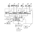
- FIG. 1 is a schematic diagram illustrating the structure of the solar module and the management system constituting the power generation site according to the present invention, and is an explanatory diagram of the types of solar modules and the monitoring system used for the construction of the power generation site.
- solar may be abbreviated as “solar module” is simply a module
- solar cell is simply a cell
- solar module set is a module set at the end.
- solar may be used with consent.
- FIG. 1 shows only three types of solar modules 7-1 , 7- S , and 7 n , 7 n includes 7 -2 to 7- (S-1) .
- S is the number of modules of the construction standard, and n is 2 to 9, but n can be S + 1, S + 2, ....
- reference numeral 7 is a single solar module (one module), 4 is an optimizer, 6 is an in-module parallel connection line (module power generation output transfer communication line), and 8 is an inter-module parallel connection line (power generation of multiple modules). Power output transport communication line) is shown.
- the monitoring / measurement / control signal of each module transmitted from the optimizer 4 is multiplexed into the power line as a multiplex signal via the PLC line (power line carrier line) using the parallel connection line 8 between the modules and output together with the power.
- the generated power output lines 8 of the plurality of modules are concentrated in the junction box 39, and the power is output to the grid line and the signal is output to the relay terminal 15 by the power / data separator installed in the junction box 39 to separate the power and the signal. Will be done.
- Reference numeral 9 is a signal path for transferring monitoring / measurement / control signals from each module to the relay terminal 15 of the power generation site, and is a PLC line (power line carrier line) using the parallel connection line 8 between modules.
- the PLC line is connected between the solar cell group or the solar module and the junction box (39), and the communication between the junction box (39) and the relay terminal (site monitoring terminal) 15 of the power generation site and the monitoring site is wired or wireless. It is transmitted via the communication line 9.
- the server 16 of the power generation site is transmitted to the remote terminal 17 via a public network such as the Internet 37, and is processed by various data processing programs mounted on the remote terminal. The processing result is displayed on the monitor 18. Further, the remote terminal 17 is configured to be able to communicate with the power conditioner 14 via the relay terminal 15.
- reference numeral 7 is a single solar module (one module), 4 is an optimizer, 6 is an in-module parallel connection line (module power generation output transfer communication line), and 8 is an inter-module parallel connection line (power generation of multiple modules). Power output transport communication line) is shown.
- the monitoring / measurement / control signals of each module transmitted from the optimizer 4 are multiplexed into the power line as a multiplex signal via the PLC line (power line carrier line) using the parallel connection line 8 between the modules and output together with the power. Will be done.
- the generated power output lines 8 of the plurality of modules are concentrated in the junction box 39, and the power is connected to the grid line and the signal is sent to the relay terminal 15 by the power / data separator 39a installed in the junction box 39 to separate the power and the signal. It is output.
- Reference numeral 9 is a signal line in which the monitoring / measurement / control signals from each module are transferred to the relay terminal 15 of the power generation site.
- the PLC line is connected between the solar cell group or the solar module and the junction box (39), and the communication between the junction box (39) and the relay terminal (site monitoring terminal) 15 of the power generation site and the monitoring site is wired or wireless. It is transmitted via the communication line 9.
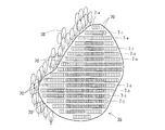
- FIG. 2 is a plan view (two-dimensional shape in top view) illustrating an example of a field (terrain such as land on which a gantry is installed) of a power generation site in which a solar module is laid according to the present invention.
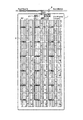
- FIG. 3 shows a state in which the solar module is laid in the field topography example of the power generation site shown in FIG. 2 by the conventional method.
- Reference numeral 35 in FIG. 2 indicates a field of a power generation site.
- This field 35 has an irregular plan view, and a shield 38 showing a tree as a representative is present around the field 35.
- the string is not installed (the part without the diagonal line) even though the space is for one string, the amount of power generation is suppressed due to the presence of the shield 38 or the like, and the string is used.
- a space (reference numeral 70) that does not contribute much to the overall power generation efficiency even if installed is shown.
- the module 7 units constituting the module set according to the present embodiment can be separated from the module set, and as will be described later in FIG. 5, the cell group 2 constituting the module 7 can be separated from the module set. Therefore, for example, the standard module set 7 n can be installed in the area (7 places) shown by the space 70 in FIG. As described above, in the present embodiment, the cell group whose power generation amount has decreased due to a malfunction, an external factor, or an internal factor is ignored or left unattended, and does not necessarily mean that it is electrically separated.
- the narrow space to install a standard module set 7 n used in conjunction one module set 7-1 to 9 modules set 7-9 to the size of the space prepare the required number of these standard module sets and module sets smaller than the standard module set in advance based on the construction drawing of the power generation site. Furthermore, the installation procedure of the module set, which is smaller than these standard module sets, is also installed as a control program in the transport means and the installation crane as a construction procedure.
- the number of modules installed in the field of the power generation site according to this embodiment shown in FIG. 2 is 477.
- the number of modules is 260 as described above. If these are simply compared, the number of modules according to this embodiment is 1.83 times the number of conventional modules. That is, in the construction method according to this embodiment, nearly twice as many modules as the conventional ones can be installed. This means that a large amount of power can be generated in a field with a fixed area.
- FIG. 4 is a schematic diagram illustrating the configuration of an embodiment of the solar module according to the present invention, in which the solar cells are grouped into groups of 4 units, and a total of 18 groups of 6 rows and 3 columns are formed into one module 7.
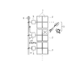
- FIG. 5 is an explanatory diagram of cell groups constituting the module, and each cell group 2 is independent of each other and is connected to the parallel connection line 6 in the module via the cell group controller 5. Then, the parallel connection lines 6 in the module of each row are concentrated on the optimizer 4. The optimizer 4 is connected in parallel to the parallel connection line 8 between modules.
- the cell group controller 5 which also has a connection / disconnection function monitors the power generation state of the cell 1 in the group, and the amount of power generation is reduced due to, for example, physical destruction or a decrease in the amount of solar radiation due to the solar shield 13 such as dust. It detects that it has fallen below the set threshold value (predetermined) and disconnects the group from the parallel connection line 6 in the module (off: ignore or leave). When the shield such as dust is removed and the amount of solar radiation recovers and exceeds the above threshold value, the cell group is connected to the parallel connection line 6 in the module again (on: contributes to power generation).
- the remote terminal 17 is processed together with the image data from the data center (see reference numeral 42 in FIG. 13) described later, and the identification of the malfunctioning module is displayed on the monitor 18 as an image or the like.
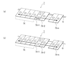
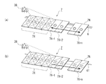
- FIG. 6 is a diagram for explaining the difference in the disconnection method at the time of a failure in the module of the solar module constituting the solar array by comparing the present invention with the prior art.
- FIG. 6A shows the module set of this embodiment.
- a problem occurs in a specific module 7X + 1
- only the module 7X + 1 is disconnected (ignored or left unattended) from the parallel connection line 6 in the module.
- Normal modules 7X and 7X + 2, 7X + n on both sides continue to generate electricity. That is, in this embodiment, it is sufficient to reduce the amount of power generation of only the module in which the defect occurs.
- the module 7X + 1 generates power that exceeds the threshold value even a little, the generated power is effectively used.
- FIG. 7 is a schematic diagram illustrating the difference in the separation method when the solar irradiation amount of the solar module constituting the solar array is reduced by comparing the prior art and the present invention.
- FIG. 7A shows the module set of this embodiment.
- the plurality of modules 7X are connected to the parallel connection line 6 in the module. Separate from (ignored or left unattended).
- the modules 7X + 1, 7X + 2, ... 7X + n can continuously generate electricity. That is, in this embodiment, power generation can be continued with the modules other than the modules whose power generation amount is below a predetermined threshold value.
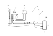
- FIG. 8 is a rear view of a main part for explaining an example of a sensor interface in the solar module according to the present invention.
- a plurality of cells are integrally fixed by a frame 71.
- the optimizer 4 is attached to a part of the back surface of the frame 71.
- a sensor group 20 is installed at an appropriate position on the frame 71 of the module.
- the sensor group includes an inclination sensor, an orientation sensor, a sunshine amount sensor (illuminance sensor), a humidity sensor, a temperature sensor, a pressure pressure sensor, and a vibration sensor.
- GPS is also a member of the sensor group.
- the output data of each sensor is multiplexed by the sensor interface 19, superimposed on the inter-module connection line 8, sent to the terminal box 39, and transferred to the relay terminal 15 (FIG. 1).
- the optimizer 4 is used for conversion processing of low voltage power (for example, 40 V or the like) taken from the parallel connection line 6 in the module (see FIG. 4 or the like described above) from its own cell by the power conditioner 14 (see FIG. 1). It is boosted to a high voltage (here, 800V) and sent to the parallel connection line 8 between modules.
- low voltage power for example, 40 V or the like
- high voltage here, 800V
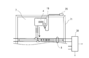
- FIG. 9 is a rear view of a main part for explaining another mounting example of the optimizer in the solar module according to the present invention.
- this configuration example which accommodates the terminal box 19 shown in FIG. 8 in the housing of the optimizer 4 is a simplified version of the rear structure of the module frame 71.
- a part or all of the sensor group 20 can be housed in the housing of the optimizer 4. This further simplifies the structure of the module.
- FIG. 10 is an explanatory diagram of an example of a solar irradiation mode for a solar module, and is a schematic diagram illustrating a change in the amount of direct sunlight and an effect of a shield on the solar array and its installation mode.
- the solar array 10 is installed on a gantry 36 provided in the field 35 of the power generation site.
- the solar array 10 is installed at an installation direction S and an installation angle D in the latitude direction with respect to the ground plane. Since the field 35 is not necessarily flat and is generally rough terrain with irregularities and undulations, the solar array 10, individual solar module sets ( 7-1 , 7 -n , 7 -S ). There may be a difference in illuminance on the surface with respect to the sun.
- the location data (location data) L of the installation location can be easily determined by GPS. The position of each solar array 10 and each module 7 can be determined.
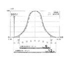
- FIG. 11 is a diagram for explaining the daily output change of the solar module by comparing the present invention with the prior art.
- the power generation voltage of the solar cell group 2 here, for example, 40V
- the tracking of the output with respect to the illuminance of the sun is speeded up and refined, and it is optimal even in unstable weather. It is possible to obtain the maximum output.
- the power generation voltage of the solar cell group 2 here, for example, 40V
- the tracking of the output with respect to the illuminance of the sun is speeded up and refined, and it is optimal even in unstable weather. It is possible to obtain the maximum output.
- by boosting each solar module to, for example, 800 V and transmitting power to the grid line, it is possible to obtain the optimum and maximum output.
- the power conditioner 14 has an AI function, and even when the photovoltaic power generation output (PV: photovoltaic power) of the solar module is low, such as in the morning and evening or on a cloudy day, as shown by the curve in FIG. It is possible to finely control the power generation output at the rising and falling parts of the output characteristic curve, and the loss at low output is reduced.
- PV photovoltaic power generation output
- the time when the power generation output of the conventional method can be taken out is 9 hours as shown in a staircase pattern in the figure.
- the solar module of this embodiment it takes 12 hours.
- FIG. 12 is a block diagram illustrating a configuration example around the optimizer of the solar module according to this embodiment.
- the configuration around the optimizer 4 in this embodiment is an example, and various modifications can be made as a means for realizing the AI function.
- the optimizer 4 includes a GPS position data acquisition means 27, a direct sunshine sensor (so-called brightness sensor) 22, which calculates and acquires position data of the solar module based on the radio waves received by the GPS antenna 21. It has a sunrise / sunset time acquisition means 28 for calculating and determining the sunrise / sunset time by referring to the calendar table 23.
- the sunlight incident angle acquisition means 29 that calculates and acquires the incident angle of sunlight based on the latitude data of the field stored in the latitude table 24, the calendar table 23, and the detection data of the inclination sensor 26. It has an installation orientation / installation angle acquisition means 30 that calculates and acquires the installation orientation / installation angle of the solar module based on the data of the orientation sensor (orientation magnet) 25 and the detection data of the inclination sensor 26.
- this optimizer 4 has an AI function executing means 31.
- the AI function executing means 31 includes a position data acquiring means 27, a sunrise / sunset time acquiring means 28, a sunlight incident angle acquiring means 29, an installation orientation / installation angle acquiring means 30, humidity, temperature, pressure, and acceleration (vibration). From the calculation results from the sensor, the environmental data surrounding the solar module, such as the time of shadow due to the shield, the tendency of the amount of solar radiation, and the tendency of the weather conditions, is inferred, judged, and learned. Based on this learning result, data for managing solar cell groups and solar modules, performing maintenance, etc. is generated.
- the output of the AI function executing means 31 is connected to the optimizer 4 and used as a control signal of the disconnection switch 5 of the solar module.
- the clock 34 supplies the standard clock data of the power generation site to the microchip 3 equipped with the AI function executing means 31.
- a determination means software, for example, RPA: Robotic Process Automation
- RPA Robotic Process Automation
- the optimizer 4 has a monitor 32 that monitors the operation of the AI function executing means 31 or the determining means.
- the monitor 32 to be monitored is a correction means for correcting the judgment of the AI function when it is judged to be unrealistic or unrealistic from the viewpoint of human intellect, and when the above judgment means is clearly judged to be incorrect. 33 is provided.
- the AI can be kept under human supervision at all times, so that the learning step can be shortened and the learning efficiency can be improved.
- the monitor 32 and the correction means 33 can be placed on the remote terminal 17 shown in FIG.
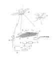
- FIG. 13 is a schematic diagram illustrating an overall image of an example of a monitoring system for a power generation site according to the present invention.
- the generated power of the solar array 10 installed in the field 35 of the power generation site is output from the power conditioner 14 to the grid line.
- various data measured by the sensor of the solar array 10 and signals for management and control are sent from the parallel connection line in the module (6 in FIG. 1) and the parallel connection line 8 between modules to the server 16 via the relay terminal. It is sent and transferred to the remote terminal 17.
- the solar array 10 in the field 35 of this power generation site is photographed by the artificial satellite 40, and the image of the photographed solar array 10 is stored in the data center 42 via the receiving station. Needless to say, the solar array 10 may be photographed by means such as a drone 43.
- the artificial satellite 40, the drone 43, etc. capture not only visible images (still images, moving images) but also various images such as thermoimages and spectroscopic data as necessary and store them in the data center 42.
- the remote terminal 17 analyzes various data measured from the server 16 and management signals, and uses the image data stored in the data center 42 to reduce the power generation capacity and disconnect the module 70. Identify.
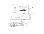
- the identified module 70 is displayed on the monitor 18 of the remote terminal 17. In this display, attention can be alerted by, for example, a red color lighting / blinking display on the screen.
- the power generation status of each solar module can be displayed on the time axis, or in a daily report, a monthly report, or other format.
- FIG. 14 is a schematic diagram illustrating an image example of a monitoring monitor terminal in an example of a monitoring system for a power generation site according to the present invention.
- the monitor 18 can display the information necessary for the operation of the power generation site, such as the display of the specified solar module and various measurement data.
- This embodiment enables efficient management of the power generation site under its jurisdiction in a remote location.
- the various data measured by the sensor, and the signals for management and control are not limited to the PLC and the communication line, and other transmission means using a wired radio can also be used.
- the power generation operation status of the solar power generation system, the individual solar modules constituting the solar power generation system, or the individual solar cells can be monitored at a remote location, and the defective solar module can be identified in real time. This can significantly reduce operating costs for large-scale solar power generation sites, such as simplification of management work including maintenance and efficiency of management personnel.
- Calendar data table 24 ... ⁇ Latitude table 25 ⁇ ⁇ ⁇ Direction sensor 26 ⁇ ⁇ ⁇ Tilt sensor 31 ⁇ ⁇ ⁇ AI 32 ... Monitor (monitor of server 16) 33 ... Corrective input means 34 ... Clock 35 ... Power generation site field 36 ... Stand 37 ... Network (Internet, etc.) 38 ... Shield 39 ... Junction box 39a ... Power / data separator 40 ... Artificial satellite 44 ... Receiver 42 ... Data center 43 ... Drone 71 ... flame
Landscapes
- Engineering & Computer Science (AREA)
- Power Engineering (AREA)
- Photovoltaic Devices (AREA)
Priority Applications (3)
| Application Number | Priority Date | Filing Date | Title |
|---|---|---|---|
| JP2021546902A JPWO2021054306A1 (cg-RX-API-DMAC7.html) | 2019-09-18 | 2020-09-15 | |
| US17/761,415 US12224705B2 (en) | 2019-09-18 | 2020-09-15 | Monitoring/control system for photovoltaic generation site |
| DE112020004421.1T DE112020004421T5 (de) | 2019-09-18 | 2020-09-15 | Überwachungs-/steuerungssystem für eine photovoltaische erzeugungsstätte |
Applications Claiming Priority (2)
| Application Number | Priority Date | Filing Date | Title |
|---|---|---|---|
| JP2019-169573 | 2019-09-18 | ||
| JP2019169573 | 2019-09-18 |
Publications (1)
| Publication Number | Publication Date |
|---|---|
| WO2021054306A1 true WO2021054306A1 (ja) | 2021-03-25 |
Family
ID=74883810
Family Applications (1)
| Application Number | Title | Priority Date | Filing Date |
|---|---|---|---|
| PCT/JP2020/034818 Ceased WO2021054306A1 (ja) | 2019-09-18 | 2020-09-15 | ソーラー発電サイトの監視・制御システム |
Country Status (4)
| Country | Link |
|---|---|
| US (1) | US12224705B2 (cg-RX-API-DMAC7.html) |
| JP (1) | JPWO2021054306A1 (cg-RX-API-DMAC7.html) |
| DE (1) | DE112020004421T5 (cg-RX-API-DMAC7.html) |
| WO (1) | WO2021054306A1 (cg-RX-API-DMAC7.html) |
Cited By (2)
| Publication number | Priority date | Publication date | Assignee | Title |
|---|---|---|---|---|
| CN113052723A (zh) * | 2021-04-17 | 2021-06-29 | 武汉瑞辉科技发展有限公司 | 基于云计算和物联网的分布式光伏发电系统运维智能管理系统 |
| WO2023243640A1 (ja) * | 2022-06-14 | 2023-12-21 | Mersintel株式会社 | ケーブルユニット |
Families Citing this family (1)
| Publication number | Priority date | Publication date | Assignee | Title |
|---|---|---|---|---|
| CN115208302A (zh) * | 2022-06-27 | 2022-10-18 | 苏州立天智能科技有限公司 | 光伏清洗装置的停机充电方法及系统 |
Citations (4)
| Publication number | Priority date | Publication date | Assignee | Title |
|---|---|---|---|---|
| US20120310427A1 (en) * | 2011-05-31 | 2012-12-06 | Williams B Jeffery | Automatic Monitoring and Adjustment of a Solar Panel Array |
| JP2019022326A (ja) * | 2017-07-18 | 2019-02-07 | Mers Fors株式会社 | ソーラーセルグループ及びソーラー発電システム |
| JP2019052954A (ja) * | 2017-09-15 | 2019-04-04 | エナジー・ソリューションズ株式会社 | 検査システム、検査方法、サーバ装置、及びプログラム |
| WO2019146665A1 (ja) * | 2018-01-25 | 2019-08-01 | クリーンエナジーファクトリー株式会社 | ソーラーモジュール |
Family Cites Families (8)
| Publication number | Priority date | Publication date | Assignee | Title |
|---|---|---|---|---|
| JPH0918046A (ja) | 1995-06-30 | 1997-01-17 | Takaaki Ikeda | 内部回転対称性を有する太陽電池工作物 |
| JP2006101581A (ja) | 2004-09-28 | 2006-04-13 | Matsushita Electric Ind Co Ltd | 系統連系インバータ |
| US8158877B2 (en) * | 2007-03-30 | 2012-04-17 | Sunpower Corporation | Localized power point optimizer for solar cell installations |
| JP2010239045A (ja) * | 2009-03-31 | 2010-10-21 | Sharp Corp | 太陽光発電システムおよび太陽光発電システム用電力線 |
| JP5467271B2 (ja) | 2009-12-24 | 2014-04-09 | 和臣 大石 | 情報処理装置及びプログラム、情報処理方法、記録媒体 |
| JP6029587B2 (ja) | 2010-10-05 | 2016-11-24 | アレンコン・アクイジション・カンパニー・エルエルシー | 高電圧エネルギーハーベスティング及び変換再生可能エネルギー公益事業規模電力システム、及び該システムのための視覚監視及び制御システム |
| JP5083425B2 (ja) * | 2011-03-04 | 2012-11-28 | ダイキン工業株式会社 | 太陽電力変換部の制御装置、及びその制御方法、及び太陽光発電装置 |
| WO2012176168A2 (en) * | 2011-06-22 | 2012-12-27 | Morgan Solar Inc. | Photovoltaic power generation system |
-
2020
- 2020-09-15 JP JP2021546902A patent/JPWO2021054306A1/ja active Pending
- 2020-09-15 DE DE112020004421.1T patent/DE112020004421T5/de active Pending
- 2020-09-15 US US17/761,415 patent/US12224705B2/en active Active
- 2020-09-15 WO PCT/JP2020/034818 patent/WO2021054306A1/ja not_active Ceased
Patent Citations (4)
| Publication number | Priority date | Publication date | Assignee | Title |
|---|---|---|---|---|
| US20120310427A1 (en) * | 2011-05-31 | 2012-12-06 | Williams B Jeffery | Automatic Monitoring and Adjustment of a Solar Panel Array |
| JP2019022326A (ja) * | 2017-07-18 | 2019-02-07 | Mers Fors株式会社 | ソーラーセルグループ及びソーラー発電システム |
| JP2019052954A (ja) * | 2017-09-15 | 2019-04-04 | エナジー・ソリューションズ株式会社 | 検査システム、検査方法、サーバ装置、及びプログラム |
| WO2019146665A1 (ja) * | 2018-01-25 | 2019-08-01 | クリーンエナジーファクトリー株式会社 | ソーラーモジュール |
Cited By (4)
| Publication number | Priority date | Publication date | Assignee | Title |
|---|---|---|---|---|
| CN113052723A (zh) * | 2021-04-17 | 2021-06-29 | 武汉瑞辉科技发展有限公司 | 基于云计算和物联网的分布式光伏发电系统运维智能管理系统 |
| CN113052723B (zh) * | 2021-04-17 | 2022-03-15 | 江苏洁诚智慧能源科技有限公司 | 基于云计算和物联网的分布式光伏发电系统运维智能管理系统 |
| WO2023243640A1 (ja) * | 2022-06-14 | 2023-12-21 | Mersintel株式会社 | ケーブルユニット |
| US12567833B2 (en) | 2022-06-14 | 2026-03-03 | Mersintel, K.K. | Cable unit |
Also Published As
| Publication number | Publication date |
|---|---|
| US12224705B2 (en) | 2025-02-11 |
| US20220376654A1 (en) | 2022-11-24 |
| DE112020004421T5 (de) | 2022-09-29 |
| JPWO2021054306A1 (cg-RX-API-DMAC7.html) | 2021-03-25 |
Similar Documents
| Publication | Publication Date | Title |
|---|---|---|
| US9086228B2 (en) | Photovoltaic power generation system and photovoltaic power generation system control method | |
| US20250125769A1 (en) | System and method for identifying defective solar panels and to quantify energy loss | |
| EP3649410B1 (en) | System for positioning solar panels in an array of solar panels to efficiently capture sunlight | |
| JP6901102B2 (ja) | 群集太陽光トラッカーの制御方法及びシステム | |
| US9773303B2 (en) | Prediction system for short-term solar irradiance and method for operating the same | |
| CN102203897B (zh) | 用于光电发生器中的能量优化的系统和方法 | |
| US12224705B2 (en) | Monitoring/control system for photovoltaic generation site | |
| KR101720669B1 (ko) | 태양광 발전장치 제어 및 모니터링 통합 시스템 | |
| JP7076764B2 (ja) | ソーラーセルグループ及びソーラー発電システム | |
| CN104408537A (zh) | 一种光伏电站优化设计系统 | |
| CN103475267A (zh) | 一种提高光伏阵列发电效率的方法 | |
| CN112271990A (zh) | 光伏系统、调节支架子系统、控制组件及光伏系统的工作方法 | |
| CN115693665A (zh) | 一种电厂发电的发电管理系统 | |
| CN121010353A (zh) | 一种用于分布式光伏项目的智能运维管理系统 | |
| AU2018356694A1 (en) | Solar power generation system | |
| CN117158217A (zh) | 一种基于光伏补光的柑橘补光系统 | |
| CN107482681B (zh) | 一种基于互联网的太阳能电池集及其监控系统和监控方法 | |
| JP7660818B2 (ja) | ソーラーモジュールを有する太陽光発電サイト | |
| CN213243890U (zh) | 光伏系统 | |
| CN214098228U (zh) | 光伏组件追踪光源装置 | |
| WO2021054303A1 (ja) | ソーラー発電サイトの施工方法 | |
| CN119543821A (zh) | 光伏阵列安装误差检测与自动校正系统 | |
| CN108549416B (zh) | 光伏板日光追踪方法及装置 | |
| CN119670435A (zh) | 集中式光伏一键化成图及自动识别调整软件 | |
| CN111654241A (zh) | 一种光伏组件阵列性能监测和故障识别的方法及系统 |
Legal Events
| Date | Code | Title | Description |
|---|---|---|---|
| 121 | Ep: the epo has been informed by wipo that ep was designated in this application |
Ref document number: 20864723 Country of ref document: EP Kind code of ref document: A1 |
|
| ENP | Entry into the national phase |
Ref document number: 2021546902 Country of ref document: JP Kind code of ref document: A |
|
| 122 | Ep: pct application non-entry in european phase |
Ref document number: 20864723 Country of ref document: EP Kind code of ref document: A1 |