WO2021049366A1 - 光ファイバの測定装置および光ファイバへの曲げ印加方法 - Google Patents
光ファイバの測定装置および光ファイバへの曲げ印加方法 Download PDFInfo
- Publication number
- WO2021049366A1 WO2021049366A1 PCT/JP2020/032998 JP2020032998W WO2021049366A1 WO 2021049366 A1 WO2021049366 A1 WO 2021049366A1 JP 2020032998 W JP2020032998 W JP 2020032998W WO 2021049366 A1 WO2021049366 A1 WO 2021049366A1
- Authority
- WO
- WIPO (PCT)
- Prior art keywords
- optical fiber
- mandrel
- tension applying
- applying member
- bending
- Prior art date
- Legal status (The legal status is an assumption and is not a legal conclusion. Google has not performed a legal analysis and makes no representation as to the accuracy of the status listed.)
- Ceased
Links
Images










Classifications
-
- G—PHYSICS
- G01—MEASURING; TESTING
- G01L—MEASURING FORCE, STRESS, TORQUE, WORK, MECHANICAL POWER, MECHANICAL EFFICIENCY, OR FLUID PRESSURE
- G01L1/00—Measuring force or stress, in general
- G01L1/24—Measuring force or stress, in general by measuring variations of optical properties of material when it is stressed, e.g. by photoelastic stress analysis using infrared, visible light, ultraviolet
- G01L1/242—Measuring force or stress, in general by measuring variations of optical properties of material when it is stressed, e.g. by photoelastic stress analysis using infrared, visible light, ultraviolet the material being an optical fibre
-
- G—PHYSICS
- G01—MEASURING; TESTING
- G01M—TESTING STATIC OR DYNAMIC BALANCE OF MACHINES OR STRUCTURES; TESTING OF STRUCTURES OR APPARATUS, NOT OTHERWISE PROVIDED FOR
- G01M11/00—Testing of optical apparatus; Testing structures by optical methods not otherwise provided for
- G01M11/08—Testing mechanical properties
- G01M11/088—Testing mechanical properties of optical fibres; Mechanical features associated with the optical testing of optical fibres
-
- G—PHYSICS
- G01—MEASURING; TESTING
- G01L—MEASURING FORCE, STRESS, TORQUE, WORK, MECHANICAL POWER, MECHANICAL EFFICIENCY, OR FLUID PRESSURE
- G01L5/00—Apparatus for, or methods of, measuring force, work, mechanical power, or torque, specially adapted for specific purposes
- G01L5/04—Apparatus for, or methods of, measuring force, work, mechanical power, or torque, specially adapted for specific purposes for measuring tension in flexible members, e.g. ropes, cables, wires, threads, belts or bands
- G01L5/10—Apparatus for, or methods of, measuring force, work, mechanical power, or torque, specially adapted for specific purposes for measuring tension in flexible members, e.g. ropes, cables, wires, threads, belts or bands using electrical means
- G01L5/105—Apparatus for, or methods of, measuring force, work, mechanical power, or torque, specially adapted for specific purposes for measuring tension in flexible members, e.g. ropes, cables, wires, threads, belts or bands using electrical means using electro-optical means
Definitions
- the present invention relates to an optical fiber measuring device and a method of applying bending to an optical fiber.
- the present application claims priority based on Japanese Patent Application No. 2019-166336 filed in Japan on September 12, 2019, the contents of which are incorporated herein by reference.
- Patent Document 1 discloses an optical fiber measuring device including a light source, a photodetector, and a roller that applies bending to the optical fiber.
- each component such as a light source, a photodetector, and a roller is arranged on substantially the same plane.
- Patent Document 1 when the optical fiber is hung around the roller, the position of the optical fiber in the vertical direction is likely to vary due to the weight of the optical fiber, or the optical fiber is likely to be wound diagonally with respect to the roller. As described above, if it is difficult to set the optical fiber, the posture (position) of the optical fiber with respect to the roller tends to vary. As a result, the radius of curvature of the bending applied to the optical fiber varies from set to set, and the measurement accuracy may become unstable.
- the present invention has been made in consideration of such circumstances, and provides an optical fiber measuring device or a method of applying bending to an optical fiber, which can improve the ease of setting an optical fiber and stabilize the measurement accuracy.
- the purpose is to do.
- the optical fiber measuring device includes a light source that emits light toward the optical fiber, a light receiving unit that receives light propagated in the optical fiber, and the like.
- a direction changing member whose both ends are optically connected to the light source and the light receiving portion to change the extending direction of the optical fiber downward, and the optical fiber hanging from the direction changing member.
- a tension applying member that applies tension to the optical fiber is provided.
- an optical fiber having both ends fixed is hung on a direction changing member, and a tension applying member is used for the optical fiber hanging from the direction changing member.
- Tension is applied, and bending is applied to the optical fiber using a plurality of mandrel arranged between the direction changing member and the tension applying member.
- an optical fiber measuring device or a method of applying bending to an optical fiber which can improve the ease of setting the optical fiber and stabilize the measurement accuracy. ..
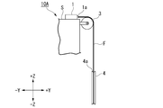
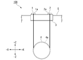
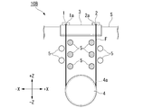
- FIG. 1A is a view of the measuring device of FIG. 1A as viewed from the left. It is a figure which looked at the measuring apparatus of FIG. 1A from the front. It is the figure which looked at the measuring apparatus which concerns on the modification of 1st Embodiment from the left. It is a figure which looked at the measuring apparatus which concerns on other modification of 1st Embodiment from the front. It is a figure which looked at the measuring apparatus which concerns on 2nd Embodiment from the front.
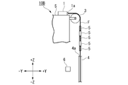
- FIG. 2A is a view of the measuring device of FIG. 2A viewed from the left. It is a figure which shows the 1st example of the shape of a mandrel.
- FIG. 8A is a view of the measuring device of FIG. 8A viewed from the left.
- the optical fiber measuring device 10A includes a stage S, a light source 1, a light receiving unit 2, a direction changing member 3, a tension applying member 4, and the like. It has.
- the measuring device 10A is a device for applying bending to the optical fiber F and measuring the characteristics of the optical fiber F.
- the light source 1 and the light receiving unit 2 may be provided inside one analyzer.
- the XYZ Cartesian coordinate system is set and the positional relationship of each configuration is described.
- the Z axis represents the vertical direction
- the X axis represents one direction orthogonal to the vertical direction
- the Y axis represents a direction orthogonal to both the Z axis and the X axis.
- the Z-axis direction is referred to as a vertical direction
- the X-axis direction is referred to as a left-right direction
- the Y-axis direction is referred to as a front-back direction.
- the + Z side indicates an upward direction
- the ⁇ Z side indicates a downward direction.
- One side (+ X side) in the left-right direction is called the right side, and the other side (-X side) is called the left side.
- One side (+ Y side) in the front-rear direction is called the front, and the other side (-Y side) is called the rear.
- the optical fiber F to be measured may be a single mode fiber.
- the specific type of the optical fiber F can be changed as appropriate.
- Stage S is a desk or the like.
- a light source 1 and a light receiving unit 2 are placed on the stage S.
- the light source 1 and the light receiving unit 2 are arranged at intervals in the left-right direction.
- the light source 1 is arranged on the left side, and the light receiving unit 2 is arranged on the right side.
- the positions of the light source 1 and the light receiving unit 2 may be reversed.
- the light source 1 emits light toward the optical fiber F.
- the first end portion of the optical fiber F is optically connected to the emission side connection portion 1a of the light source 1.
- the wavelength of the light emitted by the light source 1 and the like are appropriately changed according to the characteristics to be measured by the optical fiber F. That is, the light source 1 is configured so that the wavelength of light and the like can be changed as appropriate.
- the exit side connection portion 1a and the first end portion of the optical fiber F may be directly connected or may be connected via another optical path (optical fiber, optical waveguide). In either case, the optical fiber F and the light source 1 are optically connected.
- the light receiving unit 2 receives the light propagated in the optical fiber F.
- the second end of the optical fiber F is optically connected to the incident side connecting portion 2a of the light receiving portion 2.
- the light receiving unit 2 is configured to be able to analyze the characteristics of the optical fiber F based on the received light.
- the incident side connecting portion 2a and the second end portion of the optical fiber F may be directly connected or may be connected via another optical path (optical fiber, optical waveguide). In either case, the optical fiber F and the light receiving unit 2 are optically connected.
- the direction changing member 3 is located in front of the light source 1 and the light receiving unit 2. A part of the optical fiber F connected to the light source 1 and the light receiving unit 2 is hung on the direction changing member 3. As a result, the direction changing member 3 changes the direction of the optical fiber F extending forward from the light source 1 and the light receiving unit 2 toward the downward direction.
- the direction changing member 3 extends along the left-right direction.
- the left end portion of the direction changing member 3 is located to the left of the exit side connecting portion 1a, and the right end portion of the direction changing member 3 is located to the right of the incident side connecting portion 2a. That is, the direction changing member 3 is arranged so as to straddle the emitting side connecting portion 1a and the incident side connecting portion 2a in the left-right direction.
- the direction changing member 3 is fixed to the stage S. However, the direction changing member 3 may be fixed to a position other than the stage S (for example, a floor surface).
- the direction changing member 3 of this embodiment is formed in a columnar shape. Further, the diameter of the cylinder is smaller than ⁇ 280 mm, and a part of the optical fiber F is bent along the outer peripheral surface of the direction changing member 3. Therefore, the direction changing member 3 bends the optical fiber F so that the radius of curvature is smaller than 140 mm. Generally, a bend having a radius of curvature of 140 mm or more is not regarded as a bend when measuring the characteristics of the optical fiber F. This is because such bending with a small curvature does not easily affect the characteristics of the optical fiber F. Conversely, the direction changing member 3 of the present embodiment intentionally applies a bending of a size considered when measuring the characteristics of the optical fiber F.
- the tension applying member 4 is located below the direction changing member 3. As shown in FIG. 1B, the position of the tension applying member 4 in the front-rear direction coincides with the position of the front end portion of the direction changing member 3.
- the tension applying member 4 is configured to be movable in the vertical direction with respect to the stage S and the direction changing member 3.
- the tension applying member 4 is suspended by the optical fiber F hanging downward from the direction changing member 3.
- the tension applying member 4 applies tension to the optical fiber F by, for example, its own weight.
- the tension can be changed as appropriate, but is preferably 20 gf or less, for example.
- the tension applying member 4 is formed in a substantially disk shape. As shown in FIG. 1B, a groove 4a is formed in the central portion of the tension applying member 4 in the front-rear direction. An optical fiber F is passed through the inside of the groove 4a. By restricting the position of the optical fiber F by the groove 4a, the posture of the optical fiber F can be stabilized and the optical fiber F can be prevented from coming off from the tension applying member 4.
- the diameter of the bottom surface of the groove 4a shown in FIG. 1C is smaller than ⁇ 280 mm, and a part of the optical fiber F is bent along the bottom surface of the groove 4a. Therefore, the tension applying member 4 bends the optical fiber F so that the radius of curvature is smaller than 140 mm. That is, like the direction changing member 3, the tension applying member 4 also applies a bending of a size considered when measuring the characteristics of the optical fiber F.
- the tension applying member 4 does not have to have the groove 4a. In this case, the radius of the outer peripheral surface of the tension applying member 4 is made to match the desired radius of curvature of the optical fiber F.
- tension is applied to the optical fiber F only by the weight of the disc-shaped tension applying member 4.
- the configuration for applying tension, the shape of the tension applying member 4, and the like can be appropriately changed.
- a spring 4b that applies an upward force to the tension applying member 4 may be provided.
- the difference obtained by subtracting the elastic force of the spring 4b from the own weight of the tension applying member 4 is the tension of the optical fiber F.
- a so-called constant load spring may be used as the spring 4b.
- a constant load spring is a spring whose load does not change depending on the amount of deformation. When a constant load spring is used, the tension of the optical fiber F can be made constant regardless of the vertical position of the tension applying member 4.
- the balance structure 7 as shown in FIG. 1E may be adopted.
- the balance structure 7 has a balance rod 7a, a support portion 7b, and a weight 7c.
- the balance pole 7a is rotatably supported around the fulcrum C by the support portion 7b.
- the first end of the balance pole 7a is rotatably fixed to the tension applying member 4, and the weight 7c is attached to the second end of the balance pole 7a.
- the difference obtained by subtracting the upward force applied to the tension applying member 4 by the weight 7c from the own weight of the tension applying member 4 is the tension of the optical fiber F.
- the tension of the optical fiber F can be easily changed by changing the strength of the spring 4b. Further, by providing a load sensor that detects the load applied to the spring 4b, the tension applied to the optical fiber F can be monitored. According to the configuration of FIG. 1E, the tension of the optical fiber F can be easily changed by changing the position and mass of the weight 7c. Further, by providing a load sensor below the weight 7c or a torque sensor that detects the torque around the fulcrum C, the tension applied to the optical fiber F can be monitored.
- the tension applied to the optical fiber F by attaching or detaching a weight to the tension applying member 4 itself.
- the weight of the tension applying member 4 can be changed by changing the shape of the tension applying member 4, such as making the tension applying member 4 semicircular, and the tension applied to the optical fiber F can be changed.
- the optical fiber F to be measured is cut to a predetermined length.
- both ends of the optical fiber F are connected to the exit side connection portion 1a of the light source 1 and the incident side connection portion 2a of the light receiving portion 2.
- both ends of the optical fiber F are separated from the exit side connection portion 1a and the incident side connection portion 2a so that the optical fiber F does not come off from the exit side connection portion 1a and the incident side connection portion 2a due to the tension applied by the tension applying member 4. Fix to.
- the optical fiber F whose both ends are connected to the light source 1 and the light receiving unit 2 is hung from above on the direction changing member 3 and hung downward by its own weight.
- the direction of the optical fiber F extending forward from the light source 1 and the light receiving unit 2 toward the direction changing member 3 changes downward.
- the tension applying member 4 is brought closer to the optical fiber F hanging from the direction changing member 3 from above.
- the tension applying member 4 since the tension applying member 4 has the groove 4a, the optical fiber F is inserted inside the groove 4a. A predetermined tension is applied to the optical fiber F by the tension applying member 4, and bending along the direction changing member 3 and the tension applying member 4 is applied to the optical fiber F.
- light for measurement is emitted from the light source 1.
- the light enters the light receiving unit 2 through the optical fiber F.
- the intensity of the light or the like changes. Therefore, by analyzing the light incident on the light receiving unit 2, it is possible to evaluate the characteristics of the optical fiber F against bending.
- the light source 1 that emits light toward the optical fiber F, the light receiving unit 2 that receives the light propagating in the optical fiber F, and the optical fiber F are hung.
- the direction-changing member 3 that changes the extending direction of the optical fiber F optically connected to the light source 1 and the light-receiving part 2 and the optical fiber F that hangs down from the direction-changing member 3 are tensioned. It includes an application member 4.
- the position of the portion of the optical fiber F that is bent in contact with the direction changing member 3 and the tension applying member 4 in the vertical direction is unlikely to vary depending on the weight of the optical fiber F or the like. Therefore, it is easy to set the optical fiber F. Therefore, since the radius of curvature of the bending applied to the optical fiber is stable, it is possible to stabilize the measurement accuracy.
- the tension applying member 4 is formed with a groove 4a that regulates the position of the optical fiber F. As a result, the ease of setting the optical fiber F on the tension applying member 4 is further improved. Further, since the shape of the optical fiber F in the portion bent along the tension applying member 4 is stable, the measurement accuracy can be further stabilized.
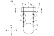
- the measuring device 10B of the present embodiment includes a plurality of mandrels 5 and positions in addition to the stage S, the light source 1, the light receiving unit 2, the direction changing member 3, and the tension applying member 4. It includes a detection unit 6.
- the position detecting unit 6 shown in FIG. 2B is configured to detect the position of the tension applying member 4 in the vertical direction.
- the plurality of mandrel 5s are arranged between the direction changing member 3 and the tension applying member 4.
- the plurality of mandrel 5s are configured to apply bending to the optical fiber F.
- a part of the mandrel 5 is arranged so as to sandwich the portion of the optical fiber F located on the left side of the tension applying member 4 in the left-right direction.
- the remaining mandrel 5 is arranged so as to sandwich the portion of the optical fiber F located on the right side of the tension applying member 4 in the left-right direction.
- the same number of mandrel 5s may be arranged on the left side and the right side of the tension applying member 4.
- the mandrel 5 arranged on the left side of the tension applying member 4 and the mandrel 5 arranged on the right side of the tension applying member 4 may be in the same vertical positions. Further, in the left-right direction, at least one mandrel 5 arranged on the left side of the tension applying member 4 and a mandrel 5 arranged on the right side of the tension applying member 4 may be provided.
- the path lines of the optical fiber F can be compactly organized. That is, the vertical dimension of the optical fiber measuring device can be shortened.
- each mandrel 5 in the front-rear direction coincides with the position of the tension applying member 4 in the front-rear direction.
- the diameter of each mandrel 5 is smaller than the diameter of the tension applying member 4.
- the diameter of each mandrel 5 may be the same as the diameter of the tension applying member 4, or may be larger than the diameter of the tension applying member 4.
- the bending (diameter) of each part can be appropriately set according to the characteristics to be measured.
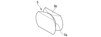
- 3A to 3C show an example of the shape of the mandrel 5.
- the mandrel 5 may have a columnar shape (disc shape) without grooves.
- the optical fiber F is bent along the outer peripheral surface of the mandrel 5.
- the radius of the outer peripheral surface of the mandrel 5 is made to match the desired radius of curvature of the optical fiber F.
- the diameter of the outer peripheral surface of the mandrel 5 in this case is smaller than ⁇ 280 mm.
- the mandrel 5 may have a groove (second groove) 5a as shown in FIG. 3B or FIG. 3C.
- the optical fiber F is bent along the bottom surface of the groove 5a.
- the radius of the bottom surface of the groove 5a is made to match the desired radius of curvature of the optical fiber F.
- the diameter of the bottom surface of the groove 5a is smaller than ⁇ 280 mm.
- both the mandrel 5 and the tension applying member 4 have a groove, the position of the mandrel 5 in the front-rear direction and the position of the tension applying member 4 in the front-rear direction are matched with each other. As a result, unnecessary bending in the front-rear direction is suppressed from being applied to the portion of the optical fiber F in contact with the mandrel 5 and the tension applying member 4. Further, the grooves of both the mandrel 5 and the tension applying member 4 can prevent the path line of the optical fiber F from being displaced in the front-rear direction.
- the mandrel 5 may have a notch 5b, as shown in FIG. 3C.
- the shape of the mandrel 5 is not limited to FIGS. 3A to 3C and can be changed as appropriate.
- the mandrel 5 in FIG. 3A may be formed with a notch 5b as shown in FIG. 3C.
- the mandrel 5 shown in FIGS. 3A to 3C may be used in combination.
- the optical fiber F whose both ends are connected to the light source 1 and the light receiving unit 2 is hung on the direction changing member 3 and hung downward. Further, tension is applied to the optical fiber F by the tension applying member 4. By applying tension, the slack of the optical fiber F is removed.
- each mandrel 5 is moved so as to sandwich the optical fiber F in between.
- each mandrel 5 moves in the left-right direction, but the direction in which the mandrel 5 moves may be changed as appropriate.
- the optical fiber F is allowed to enter the inside of the groove 5a.
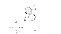
- the optical fiber F is bent along each mandrel 5, as shown in FIG. 4B.
- bending with a desired radius of curvature based on the radius of the outer peripheral surface of the mandrel 5 or the bottom surface of the groove 5a is applied to the optical fiber F.
- the optical fiber F in the five mandrel 5 arranged to the left of the tension applying member 4, the optical fiber F is bent at an angle of 90 ° along the upper mandrel 5 and the lower mandrel 5. .. Further, the optical fiber F is bent at an angle of 180 ° along the three mandrels 5 arranged between the upper mandrel 5 and the lower mandrel 5. Similarly, the optical fiber F is bent in the five mandrel 5 arranged on the right side of the tension applying member 4.
- the mandrel 5 that bends the optical fiber F at an angle of 90 ° and the mandrel 5 that bends the optical fiber F at an angle of 180 ° it is possible to bend the optical fiber F at a desired angle. ..
- the bending angle applied to the optical fiber F can be easily adjusted. Further, it becomes easy to design the path (path line) of the optical fiber F from the light source 1 to the light receiving unit 2.
- the bending angle applied to the optical fiber F is adjusted by either one of the mandrel 5 that bends the optical fiber F at an angle of 90 ° and the mandrel 5 that bends the optical fiber F at an angle of 180 °. May be good.
- the mandrel 5 Since the mandrel 5 is in contact with the optical fiber F in a state where the tension applying member 4 causes tension in the optical fiber F, it is possible to prevent the optical fiber F from remaining slack or twisted. By emitting light from the light source 1 in this state and analyzing the light in the light receiving unit 2, the characteristics of the optical fiber F against bending can be measured.
- the tension applying member 4 when the optical fiber F is not properly hung around a part of the mandrel 5, the tension applying member 4 is located below a predetermined position. .. Therefore, by detecting the position of the tension applying member 4 by the position detecting unit 6, it is possible to determine whether or not the optical fiber F is appropriately hung around all the mandrel 5.
- the arrangement of the mandrel 5 can be changed as appropriate, and for example, the arrangement as shown in FIG. 5A may be adopted.
- the mandrel 5 in FIG. 5B is moved in parallel in the left-right direction in order to achieve the state shown in FIG. 5A, the mandrel 5s come into contact with each other.
- Such a situation is particularly likely to occur when the groove 5a is formed in the mandrel 5. Therefore, as shown in FIG. 5C, by moving the mandrel 5 diagonally with respect to the left-right direction, it is possible to prevent the mandrel 5 from coming into contact with each other.
- the lower mandrel 5 when viewed from the front, the lower mandrel 5 is tilted and moves toward the + Z axis direction with respect to the left-right direction.
- the measuring device 10B of the present embodiment includes a plurality of mandrel 5s for applying bending to the optical fiber F. As a result, more bending can be applied to the optical fiber F.
- the bending can be applied to the optical fiber F by the mandrel 5, it is not essential that the bending to be measured is applied to the optical fiber F by the direction changing member 3 and the tension applying member 4. .. That is, the diameter of the outer peripheral surface of the direction changing member 3 or the outer peripheral surface of the tension applying member 4 or the bottom surface of the groove 4a in the present embodiment may be larger than ⁇ 280 mm.
- a groove (second groove) 5a that regulates the position of the optical fiber F may be formed in at least one of the plurality of mandrel 5.
- the position of the optical fiber F bent into the mandrel 5 having the groove 5a can be made more stable. Therefore, the accuracy of measurement can be made more stable.
- the grooves 4a and the second The positions of the grooves 5a in the front-rear direction may be the same.
- unnecessary bending in the front-rear direction is suppressed from being applied to the portion of the optical fiber F in contact with the mandrel 5 and the tension applying member 4.
- the grooves of both the mandrel 5 and the tension applying member 4 can prevent the path line of the optical fiber F from being displaced in the front-rear direction.
- the direction in which the plurality of mandrel 5s face each other across the optical fiber F is the horizontal direction
- at least one of the plurality of mandrel 5s can move diagonally with respect to the horizontal direction. There may be. In this case, it is possible to prevent the mandrel 5s from coming into contact with each other.
- the measuring device 10B of the present embodiment includes a position detecting unit 6 for detecting the position of the tension applying member 4 in the vertical direction.
- the plurality of mandrel 5 includes at least one mandrel 5 arranged on the left side of the tension applying member 4 in the left-right direction, and at least one mandrel 5 arranged on the right side of the tension applying member 4 in the left-right direction. May include.
- the pass line of the optical fiber F can be compactly integrated, and the vertical dimension of the optical fiber measuring device can be shortened.
- the plurality of mandrel 5s may include a mandrel 5 that bends the optical fiber F at an angle of 90 ° and a mandrel 5 that bends the optical fiber F at an angle of 180 °.
- the optical fiber F having both ends fixed is hung on the direction changing member 3, and the tension applying member 4 is used on the optical fiber F hanging from the direction changing member 3.
- Tension is applied, and bending is applied to the optical fiber F using a plurality of mandrel 5 arranged between the direction changing member 3 and the tension applying member 4. According to this configuration, the positions of the portions of the optical fiber F that are bent in contact with the direction changing member 3 and the tension applying member 4 in the vertical direction are unlikely to vary.
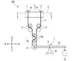
- a measuring device 10C as shown in FIG. 6A was prepared.
- the measuring device 10C includes a light source 1, a light receiving unit 2, a direction changing member 3, a tension applying member 4, three mandrel 5, a position detecting unit 6 (not shown), and a balance structure 7. ing.
- the diameter of the outer peripheral surface of the three mandrel 5 was set to ⁇ 20 mm.
- the tension applying member 4 has a groove 4a, and the diameter of the bottom surface of the groove 4a is ⁇ 280 mm.
- the bending to be measured is applied to the optical fiber F by the three mandrel 5.
- the bending applied to the optical fiber F by the tension applying member 4 is not a measurement target because the radius of curvature is 140 mm. Further, since the diameter of the direction changing member 3 is ⁇ 280 mm or more, the bending applied to the optical fiber F by the direction changing member 3 is not a measurement target.
- the mandrel 5 is moved to bring it into the state shown in FIG. 6B.
- the upper and lower mandrel 5 bend the optical fiber F at an angle of 90 °, respectively.
- the central mandrel 5 bends the optical fiber F at an angle of 180 °. Therefore, by using the measuring device 10C, bending corresponding to a radius of curvature of 10 mm ⁇ 360 ° is applied to the optical fiber F. This bending condition is the same as when the optical fiber F is wound around a cylinder having a diameter of ⁇ 20 mm for one round.
- the tension applied to the optical fiber F by the tension applying member 4 was changed in the range of 1 gf to 20 gf.
- the tension was adjusted by changing the position and weight of the weight 7c.
- ⁇ shown in Table 1 indicates the magnitude (standard deviation) of the measurement variation under each condition. Hereinafter, it will be described in more detail.
- the linear optical fiber F was connected to the light source 1 and the light receiving unit 2, and the transmitted power P1 was measured by the light receiving unit 2.
- the measurement wavelength was 1625 nm.
- the optical fiber F was manually wound around a cylinder having a diameter of ⁇ 20 mm for one round, light was emitted from the light source 1 in that state, and the transmitted power P2 was measured by the light receiving unit 2.
- the value ⁇ of the loss due to winding the optical fiber F around the mandrel can be calculated by the following mathematical formula (1).
- Example 1-1 a tension of 20 gf was applied to the optical fiber F by the tension applying member 4 and the balance structure 7.
- the measurement wavelength was 1625 nm as in the comparative example, and the transmission power P1 was measured in the state shown in FIG. 6A, and then the transmission power P2 was measured in the state shown in FIG. 6B.
- the position detection unit 6 confirmed that the tension applying member 4 was in a predetermined position. That is, it was confirmed that the optical fiber F was properly wound around the three mandrel 5.
- the bending conditions applied to the optical fiber F are substantially the same.
- the measuring device 10D includes a light source 1, a light receiving unit 2, a direction changing member 3, a tension applying member 4, 22 mandrel 5, a position detecting unit 6 (not shown), and a balance structure 7. doing. Eleven mandrels 5 were arranged so as to sandwich the optical fiber F on the ⁇ X side, and the remaining 11 mandrels 5 were arranged so as to sandwich the optical fiber F on the + X side. The diameter of the outer peripheral surface of each mandrel 5 was set to ⁇ 30 mm.
- the tension applying member 4 has a groove 4a, and the diameter of the bottom surface of the groove 4a is ⁇ 280 mm.
- a plurality of mandrel 5s are arranged in the same number in the left-right direction with the tension applying member 4 interposed therebetween.
- the bending (corresponding to a radius of curvature of 15 mm ⁇ 3600 °) to be measured is applied to the optical fiber F by the 22 mandrel 5.
- the bending applied to the optical fiber F by the tension applying member 4 is not a measurement target because the radius of curvature is 140 mm. Further, since the diameter of the direction changing member 3 is ⁇ 280 mm or more, the bending applied to the optical fiber F by the direction changing member 3 is not a measurement target.
- the tension applied to the optical fiber F by the tension applying member 4 was changed in the range of 1 gf to 20 gf.
- the tension was adjusted by changing the position and weight of the weight 7c.
- the measurement wavelength was set to 1550 nm.
- Other points are the same as in Table 1.
- the tension is preferably 20 gf or less, and more preferably 1 gf or more and 20 gf or less. Further, in Examples 2-1 to 2-7, the bending diameter is larger and the bending loss value is smaller than in Examples 1-1 to 1-7. In this way, it was possible to confirm the effectiveness of setting the tension to 1 gf or more and 20 gf or less even when the bending conditions are changed.
- the measuring device 10C shown in FIG. 6A was prepared in the same manner as the bending loss measurement described above. It is the same as the measuring device 10C used in the bending loss measurement except that the diameter of the mandrel 5 is ⁇ 60 mm.
- the cutoff wavelength of the optical fiber F was measured 10 times under each condition in Comparative Example 3 and Examples 3-1 to 3-7. The cutoff wavelength was measured according to IEC 60793-1-44.
- Comparative Example 3 bending was applied to the optical fiber F by manually winding the optical fiber F around a cylinder having a diameter of 60 mm for one round.
- Examples 3-1 to 3-7 bending was applied to the optical fiber F using the measuring device 10C.
- the bending conditions applied to the optical fiber F are substantially the same in Comparative Example 3 and Examples 3-1 to 3-7.
- the column of ⁇ in Table 2 the value of the standard deviation of the cutoff wavelength measured 10 times under each condition is shown.
- the value of the standard deviation ⁇ could be significantly reduced as compared with Comparative Example 3. Similar to the results in Table 1, it was confirmed that the measurement accuracy of the cutoff wavelength can be improved by using the measuring device 10C.
- the tension is preferably 20 gf or less, and more preferably 1 gf or more and 20 gf or less.
- the cutoff wavelength was measured by the multimode method using the measuring device 10A shown in FIG. 1A.
- the measuring device 10A includes a light source 1, a light receiving unit 2, a direction changing member 3, and a tension applying member 4.
- a cylinder having a diameter of ⁇ 280 mm was used as the direction changing member 3.
- the tension applying member 4 has a groove 4a, and the diameter of the bottom surface of the groove 4a is ⁇ 280 mm.
- Table 4 in Comparative Example 4 and Examples 4-1 to 4-7 the cutoff wavelength of the optical fiber F was measured 10 times under each condition by the multimode method.
- the cutoff wavelength was measured by the multi-mode method as follows.
- both ends of the optical fiber F were set in the light source 1 and the light receiving unit 2, and the optical fiber F was manually wound around a mandrel having a diameter of 280 mm for one round to apply bending.
- bending was applied using the measuring device 10A.
- the direction changing member 3 and the tension applying member 4 apply a bending of ⁇ 280 mm to the optical fiber F for 360 °, and no extra bending is applied to the other parts. That is, the bending conditions applied to the optical fiber F are substantially the same in Comparative Example 4 and Examples 4-1 to 4-7.
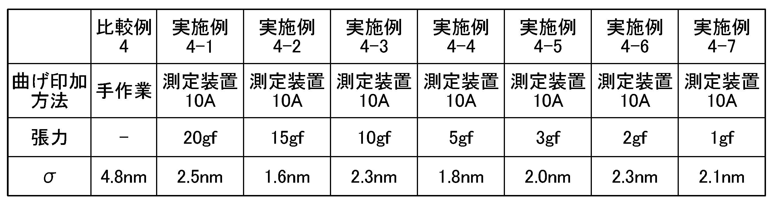
- the standard deviation ( ⁇ ) value could be significantly reduced as compared with Comparative Example 4.
- the tension is preferably 20 gf or less, and more preferably 1 gf or more and 20 gf or less.
- the measuring device 10E includes a light source 1, a light receiving unit 2, a direction changing member 3, a tension applying member 4, four mandrel 5, three mandrel 5A, a position detecting unit 6 (not shown), and a balance structure. 7 and.
- a cylinder having a diameter of ⁇ 80 mm was used as the direction changing member 3.
- the diameter of the outer peripheral surface of the four mandrel 5 was set to ⁇ 80 mm.
- the diameter of the outer peripheral surface of the three mandrel 5A was set to ⁇ 60 mm.
- the tension applying member 4 has a groove 4a, and the diameter of the bottom surface of the groove 4a is ⁇ 80 mm.
- the same number of the four mandrel 5s are arranged with the tension applying member 4 interposed therebetween in the left-right direction, and the three mandrel 5A are arranged only on the left side.
- the optical fiber The vertical dimension of the measuring device can be shortened.
- the bending to be measured is applied to the optical fiber F by the direction changing member 3, the tension applying member 4, and the four mandrel 5.
- the positions of the emitting side connecting portion 1a and the incident side connecting portion 2a in the vertical direction coincide with the positions of the upper ends of the direction changing member 3. Therefore, each portion of the optical fiber F along the direction changing member 3 is bent with a radius of curvature of 40 mm ⁇ 90 ° (see FIG. 8B).
- the optical fiber F is bent at two places by the direction changing member 3. Therefore, the bending applied to the optical fiber F by the direction changing member 3 corresponds to a radius of curvature of 40 mm ⁇ 180 °.
- Each of the four mandrel 5s applies a bend having a radius of curvature of 40 mm ⁇ 90 ° to the optical fiber F. Further, the tension applying member 4 applies bending having a radius of curvature of 40 mm ⁇ 180 ° to the optical fiber F. The three mandrel 5A apply a bend having a radius of curvature of 30 mm ⁇ (90 ° + 180 ° + 90 °) to the optical fiber F. Summing up the above, the measuring device 10E applies bending equivalent to a radius of curvature of 40 mm ⁇ 720 ° (for two rounds) and a radius of curvature of 30 mm ⁇ 360 ° (for one round) to the optical fiber F.
- the cutoff wavelength of the optical fiber F was calculated 10 times under each condition by using the bending method.
- this bending condition in addition to bending with a radius of curvature of 40 mm ⁇ 720 ° by the mandrel 5 of the measuring device 10E, transmission power before and after bending with a radius of curvature of 30 mm ⁇ 360 ° (for one round) with the mandrel 5A is used.
- the cutoff wavelength is calculated.
- Examples 5-1 to 5-7 bending was applied to the optical fiber F using the measuring device 10E. Specifically, the transmission power P1 was measured with the mandrel 5 applying a bend equivalent to a radius of curvature of 40 mm ⁇ 720 ° to the optical fiber F. Next, in addition to the bending by the mandrel 5, the transmission power P2 was measured in a state where the bending with a radius of curvature of 30 mm ⁇ 360 ° was applied to the optical fiber F by the mandrel 5A. The cutoff wavelength was measured using P1 and P2 thus obtained.
- the bending conditions applied to the optical fiber F are substantially the same in Comparative Example 5 and Examples 5-1 to 5-7.
- the column of ⁇ in Table 5 the value of the standard deviation of the cutoff wavelength measured 10 times under each condition is shown.
- the tension is preferably 20 gf or less, and more preferably 1 gf or more and 20 gf or less.
- Mode field diameter measurement In order to measure the mode field diameter under the bending application condition in which the optical fiber F is wound around a cylinder having a diameter of 60 mm, the measuring device 10C shown in FIG. 6A was prepared in the same manner as the bending loss measurement described above. It is the same as the measuring device 10C used in the bending loss measurement except that the diameter of the mandrel 5 is ⁇ 60 mm. As shown in Table 6, the mode field diameter was measured 10 times under each condition in Comparative Example 6 and Examples 6-1 to 6-7. The mode field diameter was measured according to IEC 60793-1-45.
- Comparative Example 6 bending was applied to the optical fiber F by manually winding the optical fiber F around a cylinder having a diameter of 60 mm for one round. In Examples 6-1 to 6-7, bending was applied to the optical fiber F using the measuring device 10C. The bending conditions applied to the optical fiber F are substantially the same in Comparative Example 6 and Examples 6-1 to 6-7. In the column of ⁇ in Table 6, the value of the standard deviation of the mode field diameter measured 10 times under each condition is shown.
- the tension is preferably 20 gf or less, and more preferably 1 gf or more and 20 gf or less.
- the bending loss, the cutoff wavelength, and the mode field diameter are mentioned as the characteristics to be measured of the optical fiber F.
- the measuring devices 10A to 10E of the present embodiment or the bending application method of the present embodiment can also be adopted. If the characteristic requires bending to be applied to the optical fiber F at the time of measurement, the measurement accuracy can be improved by applying this embodiment.
- the arrangement of the mandrel 5 is not limited to the example of the measuring devices 10B to 10E, and can be changed as appropriate.
- the exit side connection portion 1a and the incident side connection portion 2a do not necessarily have to face the front (+ Y side).
- the emitting side connecting portion 1a and the incident side connecting portion 2a may face upward or backward.
- the emitting side connecting portion 1a may face to the left and the incident side connecting portion 2a may face to the right.
- optical paths optical fibers, optical waveguides, etc.
- the terminals of these optical paths are connected to the exit side connection portion 1a and the incident side shown in FIG. It may be arranged at the position of the connection portion 2a.
- the distance in the left-right direction between the terminals of the optical path connected to the unit 2a may be adjusted.
- the distance in the left-right direction between the exit side connection portion 1a and the incident side connection portion 2a may be equal to the diameter of the bottom surface of the groove 4a of the tension applying member 4.
- the positions of the emitting side connecting portion 1a and the incident side connecting portion 2a in the vertical direction may be different from each other.
- the mandrel 5 having the shapes shown in FIGS. 3A to 3C may be adopted as the mandrel 5 and 5A of the measuring devices 10B to 10E.
- the spring 4b shown in FIG. 1D may be applied to the measuring devices 10B to 10E.
- the spring 4b may be used instead of the balance structure 7.
- tension may be applied to the optical fiber F by the mere weight of the tension applying member 4 without using the spring 4b or the balance structure 7.
Landscapes
- Physics & Mathematics (AREA)
- General Physics & Mathematics (AREA)
- Chemical & Material Sciences (AREA)
- Analytical Chemistry (AREA)
- Testing Of Optical Devices Or Fibers (AREA)
- Length Measuring Devices By Optical Means (AREA)
- Optical Transform (AREA)
Abstract
Description
本願は、2019年9月12日に日本に出願された特願2019-166336号に基づき優先権を主張し、その内容をここに援用する。
以下、第1実施形態に係る光ファイバの測定装置および曲げ印加方法について、図面に基づいて説明する。
図1A~図1Cに示すように、光ファイバの測定装置(以下、測定装置10Aという)は、ステージSと、光源1と、受光部2と、方向変換部材3と、張力印加部材4と、を備えている。測定装置10Aは、光ファイバFに曲げを印加し、光ファイバFの特性を測定するための装置である。なお、光源1および受光部2は、1つの分析装置の内部に設けられていてもよい。
本実施形態では、XYZ直交座標系を設定して各構成の位置関係を説明する。各図面におけるZ軸は上下方向を表し、X軸は上下方向に直交する一方向を表し、Y軸はZ軸およびX軸の双方に直交する方向を表している。以下、Z軸方向を上下方向といい、X軸方向を左右方向といい、Y軸方向を前後方向という。また、上下方向のうち+Z側は上方を示し、-Z側は下方を示している。左右方向における一方側(+X側)を右方といい、他方側(-X側)を左方という。前後方向における一方側(+Y側)を前方といい、他方側(-Y側)を後方という。
ステージSは机などである。ステージSの上に、光源1および受光部2が載置されている。光源1および受光部2は左右方向に間隔を空けて配置されている。光源1は左方、受光部2は右方に配置されている。なお、光源1および受光部2の位置は逆であっても良い。
図1Eの構成によれば、錘7cの位置や質量を変更することで、容易に光ファイバFの張力を変更することができる。また、錘7cの下方に荷重センサを設けたり、支点C回りのトルクを検出するトルクセンサを設けることで、光ファイバFに加えられる張力をモニタすることができる。
あるいは、張力印加部材4を半円状とするなど、張力印加部材4の形状を変更することによって張力印加部材4の自重を変更し、光ファイバFに加える張力を変更することも可能である。
次に、光ファイバFの両端部を、光源1の出射側接続部1aおよび受光部2の入射側接続部2aに接続する。このとき、張力印加部材4が加える張力によって光ファイバFが出射側接続部1aおよび入射側接続部2aから抜けないように、光ファイバFの両端部を出射側接続部1aおよび入射側接続部2aに固定する。
次に、方向変換部材3から垂れ下がった光ファイバFに対して、上方から、張力印加部材4を接近させる。本実施形態では張力印加部材4が溝4aを有しているため、溝4aの内側に光ファイバFを入れる。張力印加部材4によって光ファイバFに所定の張力が加えられ、光ファイバFには、方向変換部材3および張力印加部材4に沿った曲げが印加される。
次に、本発明に係る第2実施形態について説明するが、第1実施形態と基本的な構成は同様である。このため、同様の構成には同一の符号を付してその説明は省略し、異なる点についてのみ説明する。
図2Bに示す位置検出部6は、張力印加部材4の上下方向における位置を検出するように構成されている。
また、左右方向において、張力印加部材4の左方に配置されるマンドレル5と、張力印加部材の右方に配置されるマンドレル5と、を少なくとも1つずつ備えていてもよい。
マンドレル5は、図3Aに示すように、溝のない円柱状(円板状)であってもよい。図3Aのマンドレル5を用いる場合、光ファイバFはマンドレル5の外周面に沿って曲げられる。この場合には、マンドレル5の外周面の半径を、光ファイバFの所望の曲率半径に一致させる。この場合のマンドレル5の外周面の直径はφ280mmよりも小さい。
また、測定装置10Bが備える複数のマンドレル5として、図3A~図3Cに示すマンドレル5を組み合わせて用いてもよい。
図4Bの例において、張力印加部材4の左方に配置された5つのマンドレル5では、上方のマンドレル5および下方のマンドレル5に沿って、それぞれ90°の角度で光ファイバFが曲げられている。また、上方のマンドレル5と下方のマンドレル5との間に配置されている3つのマンドレル5に沿って、それぞれ180°の角度で光ファイバFが曲げられている。張力印加部材4の右方に配置された5つのマンドレル5でも、同様に光ファイバFが曲げられている。
なお、光ファイバFを90°の角度で曲げるマンドレル5と、光ファイバFを180°の角度で曲げるマンドレル5と、のうち、いずれか一方により、光ファイバFに加える曲げの角度を調整してもよい。
この状態で光源1から光を出射し、受光部2において光を分析することで、光ファイバFの曲げに対する特性を測定することができる。
なお、本実施形態の場合にはマンドレル5によって光ファイバFに曲げを印加できるため、方向変換部材3および張力印加部材4によって、測定対象となる曲げを光ファイバFに印加することは必須ではない。つまり、本実施形態における方向変換部材3の外周面または張力印加部材4の外周面または溝4aの底面の直径は、φ280mmより大きくてもよい。
図6Aに示すような測定装置10Cを用意した。測定装置10Cは、光源1と、受光部2と、方向変換部材3と、張力印加部材4と、3つのマンドレル5と、位置検出部6(不図示)と、天秤構造7と、を有している。3つのマンドレル5の外周面の直径をφ20mmとした。張力印加部材4は溝4aを有しており、溝4aの底面の直径はφ280mmである。測定装置10Cでは、3つのマンドレル5によって、測定対象となる曲げが光ファイバFに印加される。張力印加部材4によって光ファイバFに印加される曲げは、曲率半径が140mmであるため、測定対象ではない。また、方向変換部材3の直径もφ280mm以上であるため、方向変換部材3によって光ファイバFに加わる曲げも測定対象ではない。

Δ=10Log(P1/P2) …(1)
この測定を10回行い、Δの値の標準偏差を算出したところ、σ=1.52dBとなった。
実施例1-2~実施例1-7についても、実施例1-1と同様の手順でσを算出した。ただし、錘7cの位置および重さを変更することで、表1に示す通り、張力を適宜調整した。
一方、実施例1-1~1-7では、測定装置10Cを用いているため、光ファイバFに安定して曲げを印加することができる。したがって、Δのばらつきが小さくなり、σの値も小さくなったと考えられる。
以上を踏まえると、張力は20gf以下であることが好ましく、1gf以上20gf以下であることがより好ましいと言える。
ここで、複数のマンドレル5は、左右方向において、張力印加部材4を挟んで同じ数が配置されている。このように複数のマンドレル5を配置することによって、光ファイバFのパスラインをコンパクトにまとめることができるので、より安定して測定を行うことができる。
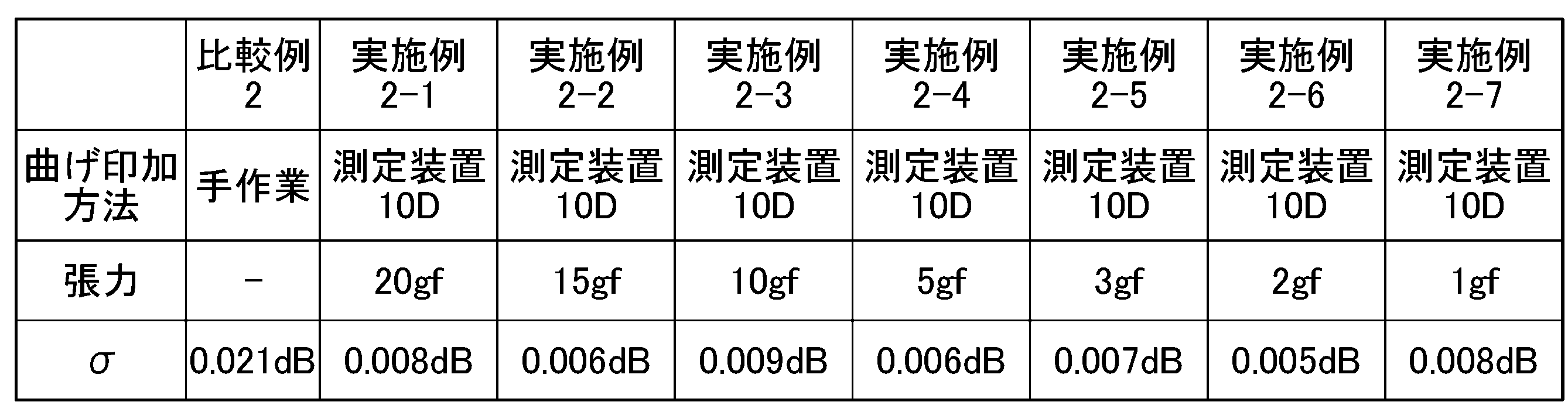
また、実施例2-1~2-7では、実施例1-1~1-7よりも、曲げ径が大きく、曲げ損失の値が小さい。このように、曲げの条件が変わった場合でも、張力を1gf以上20gf以下とすることの有効性を確認することができた。
φ60mmの円筒に光ファイバFを1周巻き付ける曲げ印加条件でのカットオフ波長を測定するため、先述の曲げ損失測定と同様に、図6Aに示す測定装置10Cを用意した。マンドレル5の直径がφ60mmである点以外は、曲げ損失測定で用いた測定装置10Cと同様である。表3に示すように、比較例3および実施例3-1~3-7として、各条件で10回ずつ、光ファイバFのカットオフ波長を測定した。カットオフ波長の測定は、IEC 60793-1-44に則って行った。
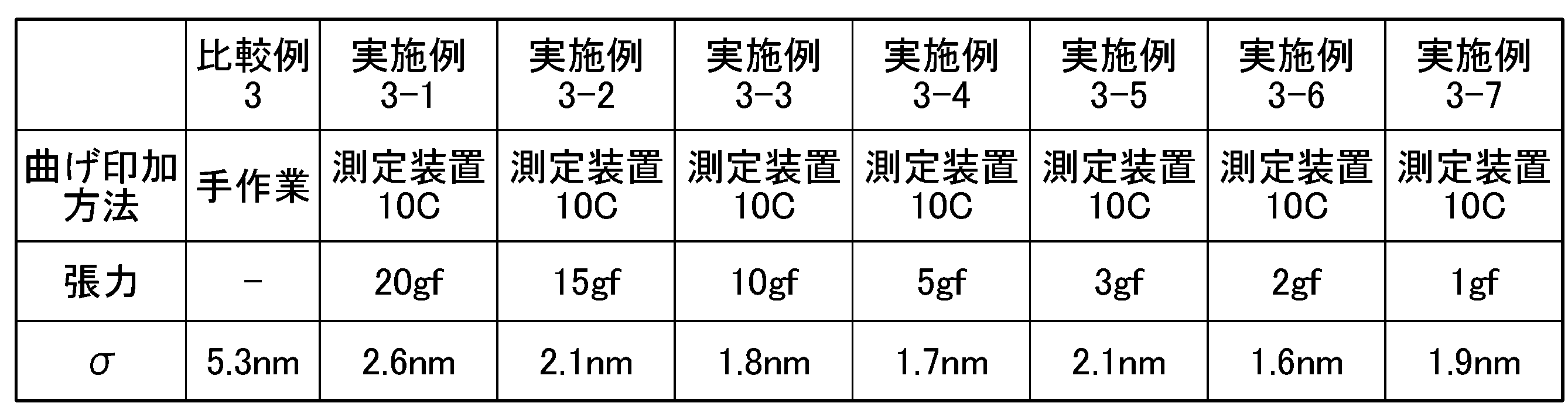
実施例3-1~3-7では、測定装置10Cを用いて光ファイバFに曲げを印加した。比較例3と実施例3-1~3-7とで、光ファイバFに加えられる曲げの条件は実質的に同じである。
表2のσの欄には、各条件のもと10回ずつ測定したカットオフ波長の標準偏差の値を示した。
表1の結果と同様に、測定装置10Cを用いることで、カットオフ波長の測定精度を向上できることが確認された。カットオフ波長を測定する際にも、張力は20gf以下であることが好ましく、1gf以上20gf以下であることがより好ましいと言える。
図1Aに示す測定装置10Aを用いてマルチモード法によるカットオフ波長を測定した。測定装置10Aは、光源1と、受光部2と、方向変換部材3と、張力印加部材4と、を有している。方向変換部材3として直径がφ280mmの円筒を用いた。張力印加部材4は溝4aを有しており、溝4aの底面の直径はφ280mmである。
表4に示すように、比較例4および実施例4-1~4-7として、各条件で10回ずつ、マルチモード法による、光ファイバFのカットオフ波長を測定した。
比較例4では、光ファイバFの両端を光源1と受光部2にセットし、φ280mmのマンドレルに手で光ファイバFを1周分巻き付けることで曲げを印加した。
実施例4-1~4-7では、測定装置10Aを用いて、曲げを印加した。方向変換部材3と、張力印加部材4により、光ファイバFには、φ280mmの曲げが360°分、印加されることとなり、それ以外の部分には、余計な曲げは加わらない。つまり、比較例4と実施例4-1~4-7とで、光ファイバFに加えられる曲げの条件は実質的に同じである。
次に、曲げの条件を変更し、図8Aに示す測定装置10Eを用いて、曲げ法によるカットオフ波長を測定した。測定装置10Eは、光源1と、受光部2と、方向変換部材3と、張力印加部材4と、4つのマンドレル5と、3つのマンドレル5Aと、位置検出部6(不図示)と、天秤構造7と、を有している。方向変換部材3として直径がφ80mmの円筒を用いた。4つのマンドレル5の外周面の直径をφ80mmとした。3つのマンドレル5Aの外周面の直径をφ60mmとした。張力印加部材4は溝4aを有しており、溝4aの底面の直径はφ80mmである。
ここで、4つのマンドレル5は、左右方向において、張力印加部材4を挟んで同じ数が配置されており、3つのマンドレル5Aは左方のみに配置されている。このように、左右方向において、張力印加部材4の左方に配置されるマンドレル5と、張力印加部材4の右方に配置されるマンドレル5と、を少なくとも1つずつ備えていれば、光ファイバの測定装置の上下方向の寸法を短くすることができる。
以上を合計すると、測定装置10Eは、曲率半径40mm×720°相当(2周分)および曲率半径30mm×360°(1周分)相当の曲げを、光ファイバFに印加する。

表5のσの欄には、各条件のもと10回ずつ測定したカットオフ波長の標準偏差の値を示した。
このように、測定装置10Eを用いることで、カットオフ波長の測定精度を向上できることが確認された。また、曲げ条件を変えてカットオフ波長を測定する際にも、張力は20gf以下であることが好ましく、1gf以上20gf以下であることがより好ましいと言える。
φ60mmの円筒に光ファイバFを1周巻き付ける曲げ印加条件でのモードフィールド径を測定するため、先述の曲げ損失測定と同様に、図6Aに示す測定装置10Cを用意した。マンドレル5の直径がφ60mmである点以外は、曲げ損失測定で用いた測定装置10Cと同じである。表6に示すように、比較例6および実施例6-1~6-7として、各条件で10回ずつ、モードフィールド径を測定した。モードフィールド径の測定は、IEC 60793-1-45に則って行った。

実施例6-1~6-7では、測定装置10Cを用いて光ファイバFに曲げを印加した。比較例6と実施例6-1~6-7とで、光ファイバFに加えられる曲げの条件は実質的に同じである。
表6のσの欄には、各条件のもと10回ずつ測定したモードフィールド径の標準偏差の値を示した。
このように、測定装置10Cを用いることで、モードフィールド径の測定精度を向上できることが確認された。また、モードフィールド径を測定する際にも、張力は20gf以下であることが好ましく、1gf以上20gf以下であることがより好ましいと言える。
また、出射側接続部1aおよび入射側接続部2aの上下方向における位置は、互いに異なっていてもよい。
また、図1Dに示したバネ4bを、測定装置10B~10Eに適用してもよい。
また、測定装置10B~10Eにおいて、天秤構造7に代えて、バネ4bを用いてもよい。あるいは、測定装置10B~10Eにおいて、バネ4bや天秤構造7を用いず、張力印加部材4の単なる自重によって光ファイバFに張力を加えてもよい。
Claims (11)
- 光ファイバに向けて光を発する光源と、
前記光ファイバ内を伝搬した光を受光する受光部と、
前記光ファイバが掛けられることで、前記光源および前記受光部に両端部が光学的に接続された前記光ファイバが延びる方向を下向きに変える方向変換部材と、
前記方向変換部材から垂れ下がった前記光ファイバに張力を加える張力印加部材と、を備える、光ファイバの測定装置。 - 前記張力印加部材に、前記光ファイバの位置を規制する溝が形成されている、請求項1に記載の光ファイバの測定装置。
- 前記光ファイバに曲げを印加する複数のマンドレルを備え、
前記複数のマンドレルは前記方向変換部材と前記張力印加部材との間に配置されている、請求項1または2に記載の光ファイバの測定装置。 - 前記複数のマンドレルのうち、少なくとも1つに、前記光ファイバの位置を規制する第2の溝が形成されている、請求項3に記載の光ファイバの測定装置。
- 前記張力印加部材に、前記光ファイバの位置を規制する溝が形成され、
上下方向から見て、前記複数のマンドレルが前記光ファイバを挟んで対向する方向を左右方向とし、前記上下方向および前記左右方向の双方に直交する方向を前後方向とするとき、
前記溝および前記第2の溝の前記前後方向の位置が一致している、請求項4に記載の光ファイバの測定装置。 - 上下方向から見て、前記複数のマンドレルが前記光ファイバを挟んで対向する方向を左右方向とするとき、
前記複数のマンドレルのうち、少なくとも1つが、前記左右方向に対して斜めに移動可能である、請求項3または5に記載の光ファイバの測定装置。 - 前記張力印加部材の上下方向における位置を検出する位置検出部を備える、請求項3から6のいずれか1項に記載の光ファイバの測定装置。
- 前記張力印加部材が前記光ファイバに加える張力は20gf以下である、請求項1から7のいずれか1項に記載の光ファイバの測定装置。
- 前記光ファイバに曲げを印加する複数のマンドレルを備え、
前記複数のマンドレルは前記方向変換部材と前記張力印加部材との間に配置され、
上下方向から見て、前記複数のマンドレルが前記光ファイバを挟んで対向する方向を左右方向とするとき、
前記複数のマンドレルは、前記左右方向において前記張力印加部材の左方に配置される少なくとも1つのマンドレルと、前記左右方向において前記張力印加部材の右方に配置される少なくとも1つのマンドレルと、を含む、請求項3から8のいずれか1項に記載の光ファイバの測定装置。 - 前記光ファイバに曲げを印加する複数のマンドレルを備え、
前記複数のマンドレルは前記方向変換部材と前記張力印加部材との間に配置され、
前記複数のマンドレルは、前記光ファイバを90°の角度で曲げるマンドレルと、前記光ファイバを180°の角度で曲げるマンドレルと、を含む、請求項3から9のいずれか1項に記載の光ファイバの測定装置。 - 両端部が固定された光ファイバを方向変換部材に掛け、
前記方向変換部材から垂れ下がった前記光ファイバに張力印加部材を用いて張力を加え、
前記方向変換部材と前記張力印加部材との間に配置された複数のマンドレルを用いて前記光ファイバに曲げを印加する、光ファイバへの曲げ印加方法。
Priority Applications (3)
| Application Number | Priority Date | Filing Date | Title |
|---|---|---|---|
| CN202080062024.3A CN114341609B (zh) | 2019-09-12 | 2020-09-01 | 光纤的测量装置以及对光纤的弯曲施加方法 |
| JP2021545234A JP7280960B2 (ja) | 2019-09-12 | 2020-09-01 | 光ファイバの測定装置および光ファイバへの曲げ印加方法 |
| US17/636,229 US12135255B2 (en) | 2019-09-12 | 2020-09-01 | Optical fiber measurement device and method for bending optical fiber |
Applications Claiming Priority (2)
| Application Number | Priority Date | Filing Date | Title |
|---|---|---|---|
| JP2019-166336 | 2019-09-12 | ||
| JP2019166336 | 2019-09-12 |
Publications (1)
| Publication Number | Publication Date |
|---|---|
| WO2021049366A1 true WO2021049366A1 (ja) | 2021-03-18 |
Family
ID=74866094
Family Applications (1)
| Application Number | Title | Priority Date | Filing Date |
|---|---|---|---|
| PCT/JP2020/032998 Ceased WO2021049366A1 (ja) | 2019-09-12 | 2020-09-01 | 光ファイバの測定装置および光ファイバへの曲げ印加方法 |
Country Status (4)
| Country | Link |
|---|---|
| US (1) | US12135255B2 (ja) |
| JP (1) | JP7280960B2 (ja) |
| CN (1) | CN114341609B (ja) |
| WO (1) | WO2021049366A1 (ja) |
Cited By (1)
| Publication number | Priority date | Publication date | Assignee | Title |
|---|---|---|---|---|
| CN116990724A (zh) * | 2023-06-28 | 2023-11-03 | 山东绿泉信息科技有限公司 | 一种光纤采集计算机接口检测装置 |
Families Citing this family (1)
| Publication number | Priority date | Publication date | Assignee | Title |
|---|---|---|---|---|
| CN118032303B (zh) * | 2024-04-13 | 2024-06-11 | 山东华光新材料技术有限公司 | 一种光纤弯曲损耗测试设备 |
Citations (4)
| Publication number | Priority date | Publication date | Assignee | Title |
|---|---|---|---|---|
| JPS61128134A (ja) * | 1984-11-26 | 1986-06-16 | Sumitomo Electric Ind Ltd | 単一モ−ド光フアイバのカツトオフ波長測定装置 |
| JPH01203938A (ja) * | 1988-02-10 | 1989-08-16 | Fujikura Ltd | 光ファイバの曲げ損失測定装置 |
| US20090026243A1 (en) * | 2005-10-21 | 2009-01-29 | Giorgio Marangoni | Method and System for Feeding a Continuous Rod of Elastomeric Material Automatically to a User Unit |
| US9389140B1 (en) * | 2015-03-05 | 2016-07-12 | Photon Kinetics, Inc. | Systems and methods for testing optical fiber |
Family Cites Families (6)
| Publication number | Priority date | Publication date | Assignee | Title |
|---|---|---|---|---|
| JP2702169B2 (ja) | 1988-08-12 | 1998-01-21 | 九州日本電気株式会社 | 半導体装置の製造装置 |
| JPH06211546A (ja) * | 1993-01-18 | 1994-08-02 | Furukawa Electric Co Ltd:The | 帯状体の偏心寸法測定方法と偏心寸法制御装置 |
| AU1671795A (en) * | 1994-02-15 | 1995-08-29 | Sumitomo Electric Industries, Ltd. | Covered optical fiber and process for producing the same |
| US6783597B2 (en) * | 2001-03-13 | 2004-08-31 | 3M Innovative Properties Company | Filament recoating apparatus and method |
| US6393923B1 (en) * | 2001-04-30 | 2002-05-28 | The United States Of America As Represented By The Secretary Of The Army | Dynamic bendloss measuring device |
| SE540086C2 (en) * | 2016-07-29 | 2018-03-20 | Maskinteknik I Oskarshamn Ab | A method for controlling a waste heat recovery system 12 |
-
2020
- 2020-09-01 CN CN202080062024.3A patent/CN114341609B/zh active Active
- 2020-09-01 WO PCT/JP2020/032998 patent/WO2021049366A1/ja not_active Ceased
- 2020-09-01 JP JP2021545234A patent/JP7280960B2/ja active Active
- 2020-09-01 US US17/636,229 patent/US12135255B2/en active Active
Patent Citations (4)
| Publication number | Priority date | Publication date | Assignee | Title |
|---|---|---|---|---|
| JPS61128134A (ja) * | 1984-11-26 | 1986-06-16 | Sumitomo Electric Ind Ltd | 単一モ−ド光フアイバのカツトオフ波長測定装置 |
| JPH01203938A (ja) * | 1988-02-10 | 1989-08-16 | Fujikura Ltd | 光ファイバの曲げ損失測定装置 |
| US20090026243A1 (en) * | 2005-10-21 | 2009-01-29 | Giorgio Marangoni | Method and System for Feeding a Continuous Rod of Elastomeric Material Automatically to a User Unit |
| US9389140B1 (en) * | 2015-03-05 | 2016-07-12 | Photon Kinetics, Inc. | Systems and methods for testing optical fiber |
Cited By (2)
| Publication number | Priority date | Publication date | Assignee | Title |
|---|---|---|---|---|
| CN116990724A (zh) * | 2023-06-28 | 2023-11-03 | 山东绿泉信息科技有限公司 | 一种光纤采集计算机接口检测装置 |
| CN116990724B (zh) * | 2023-06-28 | 2024-03-19 | 山东绿泉信息科技有限公司 | 一种光纤采集计算机接口检测装置 |
Also Published As
| Publication number | Publication date |
|---|---|
| US20220334012A1 (en) | 2022-10-20 |
| CN114341609A (zh) | 2022-04-12 |
| JPWO2021049366A1 (ja) | 2021-03-18 |
| JP7280960B2 (ja) | 2023-05-24 |
| CN114341609B (zh) | 2025-02-25 |
| US12135255B2 (en) | 2024-11-05 |
Similar Documents
| Publication | Publication Date | Title |
|---|---|---|
| US20160202418A1 (en) | Optical fiber modal distribution conditioner | |
| JP5451649B2 (ja) | モダルメトリック・ファイバセンサ | |
| US10775541B2 (en) | Optical-fiber output beam profile measurement method and optical-fiber output beam profile measurement apparatus | |
| US10422751B2 (en) | Optical fiber cord and abnormality detection system | |
| US12135255B2 (en) | Optical fiber measurement device and method for bending optical fiber | |
| US9372314B2 (en) | Optical signal processor and optical assembly | |
| WO2017110838A1 (ja) | 共焦点変位計 | |
| US9377593B2 (en) | System and method of estimating beam mode content for waveguide alignment | |
| CN103168262A (zh) | 光传输线 | |
| US20200379169A1 (en) | Mode controller | |
| US20180267077A1 (en) | Fiber-Optic Accelerometer | |
| JP2020071374A (ja) | 光ファイバ射出型レーザモジュールおよびその調整方法、ならびに光ファイバ射出型レーザモジュールの高消光比化方法 | |
| JPH05272920A (ja) | 光ファイバ変位計 | |
| KR100968942B1 (ko) | 광섬유 고정장치 | |
| CN214174138U (zh) | 光纤传感器及测量装置 | |
| JP2003247909A (ja) | 光通信用の多芯コネクタ或いは多芯ファイバアレーのフェルール偏心量測定装置における入射光照明装置および光ファイバ位置測定装置 | |
| JP2001033638A (ja) | 光ファイバ型波長フィルタ及びその波長周期調整方法 | |
| US20240255694A1 (en) | Single-mode optical fibers with low cutoff wavelength and low bend loss | |
| US20180164503A1 (en) | Mode scrambler | |
| US20200215650A1 (en) | Process fiber and laser processing system in which same is used | |
| JP4587911B2 (ja) | マルチモード光導波路の評価方法 | |
| JP2009115950A (ja) | 光ファイバ装置 | |
| Zhu et al. | 7× 10-Gb/s multicore multimode fiber transmissions for parallel optical data links | |
| CN111999815A (zh) | 一种基于少模-多模-少模结构的可调谐光纤滤波器 | |
| JP2008122674A (ja) | 光モジュールの製造方法 |
Legal Events
| Date | Code | Title | Description |
|---|---|---|---|
| 121 | Ep: the epo has been informed by wipo that ep was designated in this application |
Ref document number: 20863113 Country of ref document: EP Kind code of ref document: A1 |
|
| ENP | Entry into the national phase |
Ref document number: 2021545234 Country of ref document: JP Kind code of ref document: A |
|
| NENP | Non-entry into the national phase |
Ref country code: DE |
|
| 122 | Ep: pct application non-entry in european phase |
Ref document number: 20863113 Country of ref document: EP Kind code of ref document: A1 |
|
| REG | Reference to national code |
Ref country code: BR Ref legal event code: B01A Ref document number: 112022004152 Country of ref document: BR |
|
| REG | Reference to national code |
Ref country code: BR Ref legal event code: B01E Ref document number: 112022004152 Country of ref document: BR Free format text: ESCLARECER A DIVERGENCIA ENTRE O CONTEUDO DO PEDIDO PCT/JP2020/032998 DE 01/09/2020 ENCONTRADO NO PATENTSCOPE E O CONTEUDO APRESENTADO NA PETICAO INICIAL NO 870220019236 DE 07/03/2022, INFORMANDO O NUMERO CORRETO DO PCT REFERENTE AO CONTEUDO ENVIADO NA PETICAO INICIAL. A EXIGENCIA DEVE SER RESPONDIDA EM ATE 60 (SESSENTA) DIAS DE SUA PUBLICACAO E DEVE SER REALIZADA POR MEIO DA PETICAO GRU CODIGO DE SERVICO 207. |
|
| WWG | Wipo information: grant in national office |
Ref document number: 202080062024.3 Country of ref document: CN |