WO2021044978A1 - Spring assembly and method for manufacturing said spring assembly - Google Patents
Spring assembly and method for manufacturing said spring assembly Download PDFInfo
- Publication number
- WO2021044978A1 WO2021044978A1 PCT/JP2020/032680 JP2020032680W WO2021044978A1 WO 2021044978 A1 WO2021044978 A1 WO 2021044978A1 JP 2020032680 W JP2020032680 W JP 2020032680W WO 2021044978 A1 WO2021044978 A1 WO 2021044978A1
- Authority
- WO
- WIPO (PCT)
- Prior art keywords
- plate
- wall portion
- spring
- spring assembly
- pillar
- Prior art date
Links
Images


Classifications
-
- F—MECHANICAL ENGINEERING; LIGHTING; HEATING; WEAPONS; BLASTING
- F16—ENGINEERING ELEMENTS AND UNITS; GENERAL MEASURES FOR PRODUCING AND MAINTAINING EFFECTIVE FUNCTIONING OF MACHINES OR INSTALLATIONS; THERMAL INSULATION IN GENERAL
- F16F—SPRINGS; SHOCK-ABSORBERS; MEANS FOR DAMPING VIBRATION
- F16F1/00—Springs
- F16F1/02—Springs made of steel or other material having low internal friction; Wound, torsion, leaf, cup, ring or the like springs, the material of the spring not being relevant
- F16F1/04—Wound springs
- F16F1/12—Attachments or mountings
-
- F—MECHANICAL ENGINEERING; LIGHTING; HEATING; WEAPONS; BLASTING
- F16—ENGINEERING ELEMENTS AND UNITS; GENERAL MEASURES FOR PRODUCING AND MAINTAINING EFFECTIVE FUNCTIONING OF MACHINES OR INSTALLATIONS; THERMAL INSULATION IN GENERAL
- F16F—SPRINGS; SHOCK-ABSORBERS; MEANS FOR DAMPING VIBRATION
- F16F3/00—Spring units consisting of several springs, e.g. for obtaining a desired spring characteristic
- F16F3/02—Spring units consisting of several springs, e.g. for obtaining a desired spring characteristic with springs made of steel or of other material having low internal friction
- F16F3/04—Spring units consisting of several springs, e.g. for obtaining a desired spring characteristic with springs made of steel or of other material having low internal friction composed only of wound springs
Definitions
- the present invention relates to a spring assembly that holds a plurality of springs and a method for manufacturing the spring assembly.
- Patent Document 1 discloses a spring assembly in which a plurality of coil springs are arranged on a substrate in a vertical posture.
- the substrate of this spring assembly has a spring receiving portion formed to support the end portion of the coil spring, and the spring receiving portion is projected by embossing and then a large-diameter punch is opposed to the projecting direction. By pressing in the direction, the peripheral edge of the protrusion is crushed and the end of the coil spring is fixed.
- the end portion of the coil spring in the process of crushing the peripheral edge of the spring receiving portion, the end portion of the coil spring may be deformed so as to increase the diameter, and the coil spring may be tilted with respect to the vertical direction of the substrate.
- An object of the present invention is to provide a technique for suppressing deformation of a countersunk portion in a spring assembly in which a countersunk portion of a spring is attached to a plate made of a metal material.
- a spring assembly includes a plurality of springs and a plate formed of a metal material and supporting a countersunk portion of the plurality of springs.
- the plate has a pillar portion that protrudes from the surface of the plate and is wound around the end turn portion, and a wall portion that stands upright from the end surface of the pillar portion. The wall portion is bent outward in the radial direction to support the end turn portion.
- the spring assembly comprises a plurality of springs and a plate made of a metal material and supporting the end turns of the plurality of springs.
- the plate has a recess that is recessed from the surface of the plate and into which a countersunk portion is inserted, and a wall portion that stands upright from the surface at the periphery of the recess. The wall portion is bent inward in the radial direction to support the end turn portion.
- Yet another aspect of the present invention is a method of manufacturing a spring assembly comprising a plurality of springs and a plate formed of a metal material to support the end turns of the plurality of springs.
- This method includes a step of forming a pillar portion protruding from the surface of the plate and a wall portion erected from the end face of the pillar portion, a step of placing the end turn portion on the surface around the pillar portion, and a processing tool. It includes a step of pushing the wall portion from the inside of the wall portion toward the pillar portion to bend the wall portion radially outward. In the step of bending the wall portion, the wall portion is bent so that the processing tool does not hit the pillar portion at least at the initial stage of pushing.
- FIG. 5A is a cross-sectional view of the support structure of the second modification
- FIG. 5B is a cross-sectional view of the support structure of the third modification. It is a figure for demonstrating the support structure of the 4th modification.
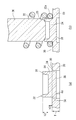
- FIG. 1 is a partial cross-sectional view of the spring assembly 10 of the embodiment.
- the spring assembly 10 includes a plate 20 and a plurality of springs 22 supported by the plate 20.
- FIG. 1 shows an enlarged support portion of the spring 22 in the spring assembly 10, and in reality, a plurality of springs 22 are supported in parallel with the plate 20. Further, a pair of plates 20 may be provided so as to support both ends of the spring 22.
- the spring assembly 10 is provided in the clutch mechanism of the transmission of the vehicle, functions as an elastic body for returning the position of the piston, and is provided on the outer circumference or the inner circumference of the pipe member.
- the spring assembly 10 can be expanded and contracted in the axial direction of the spring 22 to urge the piston.
- the axial direction of the spring 22 is simply referred to as the axial direction.
- the plate 20 is made of a metal material and is formed in a plate shape to support the end-winding portions 22a of the plurality of springs 22.
- the plate 20 is formed in an annular shape, but the plate 20 is not limited to the annular shape and may be formed in a rectangular shape. In any case, the plate 20 supports a plurality of springs 22.
- the plate 20 has a plurality of spring support structures 32 formed by the pillar portion 24, the wall portion 26, and the recess portion 28.
- the pillar portion 24 protrudes from the surface 30 of the plate 20 and is formed in a columnar shape.
- the wall portion 26 is erected from the peripheral edge of the upper end surface of the pillar portion 24, is formed in a cylindrical shape, and is processed so as to bend outward in the radial direction. Since the pillar portion 24 is provided so as to have a higher rigidity than the wall portion 26, it is difficult to be deformed when the wall portion 26 is bent, and the diameter expansion of the end turn portion 22a of the spring 22 is suppressed.
- the wall portion 26 may be formed so that the plate thickness becomes thinner toward the tip, and may be formed so that the plate thickness becomes uniform toward the tip.
- the recessed portion 28 is formed on the back side of the pillar portion 24 and the wall portion 26, and is located at the bottom of the pillar portion 24.
- the recessed portion 28 forms a columnar recessed space.
- the axial height of the recess 28 is smaller than the plate thickness of the plate 20, and the diameter of the recess 28 is larger than the diameter of the column 24.
- the recessed portion 28 is formed by a half punching process when the pillar portion 24 and the wall portion 26 are projected toward the surface 30 side.
- the pillar portion 24 is supported by the base portion 34 of the main body of the plate 20.
- the spring 22 is a coil spring, and a plurality of springs 22 are side by side and are supported by the support structure 32.
- the coil diameter of the end turn portion 22a of the spring 22 is formed to be smaller than the coil diameter other than the end winding portion 22a.
- the end turn portion 22a is located on the radial outer side of the pillar portion 24 so as to wind around the pillar portion 24, and is supported by the wall portion 26 bent outward in the radial direction so as not to come off from the outer periphery of the pillar portion 24.
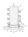
- FIG. 2 is a diagram for explaining a manufacturing process of the spring assembly 10.
- the pillar portion 24, the wall portion 26, and the recessed portion 28 shown in FIG. 2A are formed on the flat plate 20 by press working. By pressing from the back side of the plate 20 by the method of half punching, the recessed portion 28 is formed, and the pillar portion 24 and the wall portion 26 are formed so as to protrude from the surface 30.
- the base portion 34 can be secured by making the axial height h1 of the recessed portion 28 smaller than the plate thickness T of the plate 20.
- the axial height h1 of the recess 28 may be set to 1/2 or less at 1/3 or more of the plate thickness T of the plate 20.
- the axial height h2 of the wall portion 26 is set based on the wire diameter d of the spring 22, and is set, for example, in the range of 0.5d to 1.5d. Further, the axial height h3 of the pillar portion 24 is set based on the wire diameter d of the spring 22, and is set, for example, in the range of 0.2d to 1.0d. As a result, the wall portion 26 prevents the end winding portion 22a from coming off, and the pillar portion 24 can suppress the diameter expansion of the end winding portion 22a.
- the spring 22 is extrapolated from the pillar portion 24 and the wall portion 26, and the end turn portion 22a is placed on the surface 30 of the plate 20 around the pillar portion 24, and the pillar portion is formed. It is provided so as to wind around the outer circumference of the 24.
- the outer diameter of the pillar portion 24 and the inner diameter of the end turn portion 22a may be substantially the same.
- the wall portion 26 is bent by the columnar processing tool 36.
- the tip of the processing tool 36 has a tapered pressing surface 36a.
- the processing tool 36 moves forward and backward in the axial direction by a drive source such as a motor.
- the processing tool 36 advances toward the plate 20 with respect to the plate 20 placed on the processing table, is inserted inside the spring 22, and the pressing surface 36a is the inner peripheral edge of the wall portion 26 before bending. Contact.
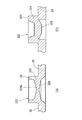
- FIG. 3 is a diagram for explaining the manufacturing process of the spring assembly 10, and shows the continuation of the manufacturing process shown in FIG. 2 (b).
- FIG. 3 shows a step of bending the wall portion 26 outward in the radial direction using the processing tool 36, and shows a step after arranging the spring 22 shown in FIG. 2 (b).
- the processing tool 36 is pushed toward the pillar portion 24, and the pressing surface 36a bends the wall portion 26 outward in the radial direction.
- the processing tool 36 advances by a preset distance.
- the spring 22 is supported so that the wall portion 26 prevents the end winding portion 22a from coming off.
- the pillar portion 24 is provided so as to have higher rigidity than the wall portion 26, it is difficult to be deformed. Can be suppressed from expanding in diameter.
- the pillar portion 24 it is possible to prevent the end turn portion 22a from being partially expanded in diameter due to the attachment by the wall portion 26, and to prevent the spring 22 from being attached in a tilted state. it can.
- the wall portion 26 is bent so that the processing tool 36 does not hit the upper end surface 24a of the pillar portion 24 at least at the initial stage of pushing.
- the pushing distance of the processing tool 36 may be a distance that finally hits the upper end surface 24a of the pillar portion 24, but it is preferable that the pushing distance is set so as not to directly press the pillar portion 24, and the pushing distance is close to the upper end surface 24a at zero distance. It may be set to push it to the desired position. Further, the processing tool 36 may be set so as not to hit the upper end surface 24a of the column portion 24 by pushing. As a result, the pillar portion 24 can be less likely to be deformed in the step of bending the wall portion 26.
- the step of bending the wall portion 26 may be simultaneously executed by using the plurality of processing tools 36 on the plurality of support structures 32, or may be executed one by one on the plurality of support structures 32.
- FIG. 4 is a diagram for explaining the support structure 132 of the first modification.
- FIG. 4A is a perspective view of the support structure 132
- FIG. 4B is a perspective sectional view of the support structure 132.
- the support structure 132 shown in FIG. 4A has the same shape of the pillar portion 24 and the recessed portion 28 as the support structure 32 shown in FIG. 2A, but the shape of the wall portion 126 is different.
- a plurality of wall portions 126 are formed along the peripheral edge of the pillar portion 24, and are arranged apart from each other in the circumferential direction.
- the wall portion 126 has a shape in which a slit is provided in the cylindrical wall portion 26 shown in FIG. 2A, and is formed in a substantially cylindrical shape as a whole. By separating the wall portion 126 in the circumferential direction in this way, the wall portion 126 can be easily bent.
- FIG. 5A is a cross-sectional view of the support structure 232 of the second modification
- FIG. 5B is a cross-sectional view of the support structure 332 of the third modification.
- the support structure 232 shown in FIG. 5 (a) has a different shape of the pillar portion 224 and the recessed portion 228 as compared with the support structure 32 shown in FIG. 2 (a), and the support structure 332 shown in FIG. 5 (b) has a support structure 332.
- the thickness of the wall portion 326 and the shape of the recessed portion 328 are different.
- the pillar portion 224 is formed so that the front surface 224a and the back surface are recessed toward the center.
- the back surface of the pillar portion 224 is the upper surface of the recess portion 228.
- the recessed portion 228 is formed in a substantially conical shape.
- the pillar portion 224 and the wall portion 26 that are projected by the half punching process can be raised by the amount that the center is thinned, and the axial heights of the pillar portion 224 and the wall portion 26 from the surface 30 of the plate 20 can be increased by the plate 20. It is possible to make it larger than the plate thickness of.
- the recessed portion 328 shown in FIG. 5B is formed so that the upper surface protrudes toward the center and the peripheral edge side is recessed from the center.
- the diameter of the recessed portion 328 is smaller than the outer diameter of the wall portion 326 and larger than the inner diameter of the wall portion 326.
- the recessed portion 328 is formed by being recessed to the same extent as the plate thickness of the plate 20.
- the wall portion 326 is formed to be thicker than the wall portion 26 shown in FIG. 2 (a).
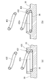
- FIG. 6 is a diagram for explaining the support structure 432 of the fourth modification.
- FIG. 6A shows a state before the wall portion 426 is bent
- FIG. 6B shows a state in which the wall portion 426 is bent.
- the support structure 432 shown in FIG. 6B is different from the support structure 32 shown in FIG. 1 in that the spring 422 is supported from the outside in the radial direction.
- the support structure 432 is composed of a wall portion 426 and a recess 38.
- the wall portion 426 is formed so as to stand upright from the surface 30 of the plate 20 at the peripheral edge of the recess 38.
- the recess 38 is formed inside the wall portion 426 and is recessed from the surface 30 of the plate 20.
- the wall portion 426 is a portion protruding from the surface 30, the recess 38 is a portion recessed from the surface 30, and the wall portion 426 and the recess 38 form a columnar recessed space.
- FIG. 6A shows a state in which the end turn portion 422a of the spring 422 is inserted into the recess 38 after the wall portion 426 and the recess 38 are formed on the plate 20.
- the coil diameter of the countersunk portion 422a is larger than the coil diameter of the portion of the spring 422 other than the countersunk portion 422a.
- the wall portion 426 After inserting the countersunk portion 422a into the recess 38, the wall portion 426 is bent inward in the radial direction as shown in FIG. 6B to support the countersunk portion 422a.
- the recess 38 recessed from the surface 30 of the plate 20 is less likely to be deformed, so that the diameter reduction of the end turn portion 422a is suppressed and the spring 422 is prevented from falling.
- the winding portion 22a of the spring 22 is formed to be smaller than the coil diameter other than the end winding portion 22a, but the present invention is not limited to this embodiment, and the coil diameters of the spring 22 are all uniformly formed. May be good.
- a spring assembly may be formed with both ends of the spring 422 attached to the two plates 20 and the spring 422 sandwiched between the two plates 20.
- the present invention relates to a spring assembly that holds a plurality of springs and a method for manufacturing the spring assembly.
Landscapes
- Engineering & Computer Science (AREA)
- General Engineering & Computer Science (AREA)
- Mechanical Engineering (AREA)
- Springs (AREA)
Abstract
This spring assembly 10 comprises a plurality of springs 22, and a plate 20 that is formed of a metal material and supports seat winding sections 22a of the plurality of springs 22. A column section 24 of the plate 20 protrudes from a surface 30 of the plate 20 and is wound around the seat winding section 22a. A wall section 26 of the plate 20 is raised from an end surface of the column section 24, is bent radially outward, and supports the seat winding section 22a.
Description
本発明は、複数のバネを保持するばね組立体そのばね組立体の製造方法に関する。
The present invention relates to a spring assembly that holds a plurality of springs and a method for manufacturing the spring assembly.
特許文献1には、複数のコイルばねを垂直姿勢で基板に配置したスプリング組立体が開示される。このスプリング組立体の基板は、コイルばねの端部を支持するために形成されたばね受け部を有し、ばね受け部は、エンボス加工により突出された後、大径のポンチをその突出方向と逆方向に打圧することで突起の周縁を潰してコイルばねの端部を止め付ける。
Patent Document 1 discloses a spring assembly in which a plurality of coil springs are arranged on a substrate in a vertical posture. The substrate of this spring assembly has a spring receiving portion formed to support the end portion of the coil spring, and the spring receiving portion is projected by embossing and then a large-diameter punch is opposed to the projecting direction. By pressing in the direction, the peripheral edge of the protrusion is crushed and the end of the coil spring is fixed.
特許文献1の技術では、ばね受け部の周縁を潰す工程において、コイルばねの端部が拡径するように変形してしまい、コイルばねを基板の垂直方向に対して傾斜させる可能性がある。
In the technique of Patent Document 1, in the process of crushing the peripheral edge of the spring receiving portion, the end portion of the coil spring may be deformed so as to increase the diameter, and the coil spring may be tilted with respect to the vertical direction of the substrate.
本発明の目的は、ばねの座巻部を金属材料のプレートに取り付けるばね組立体において、座巻部の変形を抑える技術を提供することにある。
An object of the present invention is to provide a technique for suppressing deformation of a countersunk portion in a spring assembly in which a countersunk portion of a spring is attached to a plate made of a metal material.
上記課題を解決するために、本発明のある態様のばね組立体は、複数のばねと、金属材料で形成され、複数のばねの座巻部を支持するプレートと、を備える。プレートは、プレートの表面より突出し、座巻部に巻回される柱部と、柱部の端面から立設する壁部と、を有する。壁部は、径方向外向きに屈曲されて座巻部を支持する。
In order to solve the above problems, a spring assembly according to an embodiment of the present invention includes a plurality of springs and a plate formed of a metal material and supporting a countersunk portion of the plurality of springs. The plate has a pillar portion that protrudes from the surface of the plate and is wound around the end turn portion, and a wall portion that stands upright from the end surface of the pillar portion. The wall portion is bent outward in the radial direction to support the end turn portion.
本発明の別の態様もまた、ばね組立体である。このばね組立体は、複数のばねと、金属材料で形成され、複数のばねの座巻部を支持するプレートと、を備える。プレートは、プレートの表面より凹み、座巻部を差し込まれる凹部と、凹部の周縁にて表面から立設する壁部と、を有する。壁部は、径方向内向きに屈曲されて座巻部を支持する。
Another aspect of the present invention is also a spring assembly. The spring assembly comprises a plurality of springs and a plate made of a metal material and supporting the end turns of the plurality of springs. The plate has a recess that is recessed from the surface of the plate and into which a countersunk portion is inserted, and a wall portion that stands upright from the surface at the periphery of the recess. The wall portion is bent inward in the radial direction to support the end turn portion.
本発明のさらに別の態様は、複数のばねと、金属材料で形成されて複数のばねの座巻部を支持するプレートと、を備えるばね組立体の製造方法である。この方法は、プレートに、プレートの表面より突出する柱部および柱部の端面から立設する壁部を形成するステップと、座巻部を柱部の周りの表面に載せるステップと、加工具を壁部の内側に当てた状態から柱部に向かって押し込んで壁部を径方向外向きに屈曲させるステップと、を含む。壁部を屈曲させるステップにおいて、少なくとも押し込み初期時には加工具を柱部に当てないように壁部を屈曲させる。
Yet another aspect of the present invention is a method of manufacturing a spring assembly comprising a plurality of springs and a plate formed of a metal material to support the end turns of the plurality of springs. This method includes a step of forming a pillar portion protruding from the surface of the plate and a wall portion erected from the end face of the pillar portion, a step of placing the end turn portion on the surface around the pillar portion, and a processing tool. It includes a step of pushing the wall portion from the inside of the wall portion toward the pillar portion to bend the wall portion radially outward. In the step of bending the wall portion, the wall portion is bent so that the processing tool does not hit the pillar portion at least at the initial stage of pushing.
本発明によれば、ばねの座巻部を金属材料のプレートに取り付けるばね組立体において、座巻部の変形を抑える技術を提供できる。
According to the present invention, in a spring assembly in which a countersunk portion of a spring is attached to a plate made of a metal material, it is possible to provide a technique for suppressing deformation of the countersunk portion.
図1は、実施例のばね組立体10の部分断面図である。ばね組立体10は、プレート20と、プレート20に支持される複数のばね22とを備える。図1では、ばね組立体10におけるばね22の支持部分を拡大して示しており、実際には、複数のばね22がプレート20に並列に支持される。また、プレート20は、ばね22の両端を支持するように一対設けられてよい。
FIG. 1 is a partial cross-sectional view of the spring assembly 10 of the embodiment. The spring assembly 10 includes a plate 20 and a plurality of springs 22 supported by the plate 20. FIG. 1 shows an enlarged support portion of the spring 22 in the spring assembly 10, and in reality, a plurality of springs 22 are supported in parallel with the plate 20. Further, a pair of plates 20 may be provided so as to support both ends of the spring 22.
ばね組立体10は、車両のトランスミッションのクラッチ機構に設けられ、ピストンの位置を戻す弾性体として機能し、管部材の外周または内周に設けられる。ばね組立体10は、ばね22の軸方向に伸縮可能であり、ピストンを付勢する。なお、以下の説明では、ばね22の軸方向を単に軸方向という。
The spring assembly 10 is provided in the clutch mechanism of the transmission of the vehicle, functions as an elastic body for returning the position of the piston, and is provided on the outer circumference or the inner circumference of the pipe member. The spring assembly 10 can be expanded and contracted in the axial direction of the spring 22 to urge the piston. In the following description, the axial direction of the spring 22 is simply referred to as the axial direction.
プレート20は、金属材料で板状に形成され、複数のばね22の座巻部22aを支持する。プレート20は、円環状に形成されるが、円環状に限らず、矩形状に形成されてもよい。いずれにしても、プレート20は複数のばね22を支持する。
The plate 20 is made of a metal material and is formed in a plate shape to support the end-winding portions 22a of the plurality of springs 22. The plate 20 is formed in an annular shape, but the plate 20 is not limited to the annular shape and may be formed in a rectangular shape. In any case, the plate 20 supports a plurality of springs 22.
プレート20は、柱部24、壁部26および窪み部28によって形成されるばね支持構造32を複数有する。柱部24は、プレート20の表面30より突出して円柱状に形成される。壁部26は、柱部24の上端面の周縁から立設し、円筒状に形成された後、径方向外向きに屈曲するよう加工されている。柱部24は、壁部26よりも剛性が高くなるように設けられているので、壁部26の屈曲加工時に変形しづらく、ばね22の座巻部22aの拡径を抑える。また、壁部26が形成されても壁部26の内側のプレート20が貫通していないため、ばね組立体10の剛性を確保することができる。壁部26は、先端に向かって板厚が薄くなるように形成されてよく、先端に向かって板厚が均一になるように形成されてもよい。
The plate 20 has a plurality of spring support structures 32 formed by the pillar portion 24, the wall portion 26, and the recess portion 28. The pillar portion 24 protrudes from the surface 30 of the plate 20 and is formed in a columnar shape. The wall portion 26 is erected from the peripheral edge of the upper end surface of the pillar portion 24, is formed in a cylindrical shape, and is processed so as to bend outward in the radial direction. Since the pillar portion 24 is provided so as to have a higher rigidity than the wall portion 26, it is difficult to be deformed when the wall portion 26 is bent, and the diameter expansion of the end turn portion 22a of the spring 22 is suppressed. Further, even if the wall portion 26 is formed, the plate 20 inside the wall portion 26 does not penetrate, so that the rigidity of the spring assembly 10 can be ensured. The wall portion 26 may be formed so that the plate thickness becomes thinner toward the tip, and may be formed so that the plate thickness becomes uniform toward the tip.
窪み部28は、柱部24および壁部26の裏側に形成され、柱部24の底に位置する。窪み部28は、円柱状の窪み空間を形成している。窪み部28の軸方向高さは、プレート20の板厚より小さく、窪み部28の直径は、柱部24の直径より大きい。窪み部28は、柱部24および壁部26を表面30側に突出させる際の半抜き加工によって形成される。柱部24は、プレート20の本体の土台部分34に支えられる。
The recessed portion 28 is formed on the back side of the pillar portion 24 and the wall portion 26, and is located at the bottom of the pillar portion 24. The recessed portion 28 forms a columnar recessed space. The axial height of the recess 28 is smaller than the plate thickness of the plate 20, and the diameter of the recess 28 is larger than the diameter of the column 24. The recessed portion 28 is formed by a half punching process when the pillar portion 24 and the wall portion 26 are projected toward the surface 30 side. The pillar portion 24 is supported by the base portion 34 of the main body of the plate 20.
ばね22は、コイルばねであって、複数並んで支持構造32に支持される。ばね22の座巻部22aのコイル径は、座巻部22a以外のコイル径より小さくなるように形成される。座巻部22aは、柱部24を巻回するよう柱部24の径方向外側に位置し、径方向外向きに屈曲した壁部26により柱部24の外周から抜けないように支持される。
The spring 22 is a coil spring, and a plurality of springs 22 are side by side and are supported by the support structure 32. The coil diameter of the end turn portion 22a of the spring 22 is formed to be smaller than the coil diameter other than the end winding portion 22a. The end turn portion 22a is located on the radial outer side of the pillar portion 24 so as to wind around the pillar portion 24, and is supported by the wall portion 26 bent outward in the radial direction so as not to come off from the outer periphery of the pillar portion 24.
図2は、ばね組立体10の製造工程について説明するための図である。平板状のプレート20にプレス加工によって、図2(a)に示す柱部24、壁部26および窪み部28が形成されている。半抜き加工の手法によりプレート20の裏側からプレスすることで、窪み部28が形成されるとともに、柱部24および壁部26が表面30より突出するように形成される。ここで、窪み部28の軸方向高さh1をプレート20の板厚Tより小さくすることで、土台部分34を確保できる。なお、窪み部28の軸方向高さh1は、プレート20の板厚Tの1/3以上で1/2以下に設定されてよい。
FIG. 2 is a diagram for explaining a manufacturing process of the spring assembly 10. The pillar portion 24, the wall portion 26, and the recessed portion 28 shown in FIG. 2A are formed on the flat plate 20 by press working. By pressing from the back side of the plate 20 by the method of half punching, the recessed portion 28 is formed, and the pillar portion 24 and the wall portion 26 are formed so as to protrude from the surface 30. Here, the base portion 34 can be secured by making the axial height h1 of the recessed portion 28 smaller than the plate thickness T of the plate 20. The axial height h1 of the recess 28 may be set to 1/2 or less at 1/3 or more of the plate thickness T of the plate 20.
壁部26の軸方向高さh2は、ばね22の線径dにもとづいて設定され、例えば0.5dから1.5dの範囲で設定される。また、柱部24の軸方向高さh3は、ばね22の線径dにもとづいて設定され、例えば0.2dから1.0dの範囲に設定される。これにより、壁部26により座巻部22aを抜け止めしつつ、柱部24により座巻部22aの拡径を抑えることができる。
The axial height h2 of the wall portion 26 is set based on the wire diameter d of the spring 22, and is set, for example, in the range of 0.5d to 1.5d. Further, the axial height h3 of the pillar portion 24 is set based on the wire diameter d of the spring 22, and is set, for example, in the range of 0.2d to 1.0d. As a result, the wall portion 26 prevents the end winding portion 22a from coming off, and the pillar portion 24 can suppress the diameter expansion of the end winding portion 22a.
次に、図2(b)に示すように、ばね22が柱部24および壁部26を外挿され、座巻部22aが柱部24の周りのプレート20の表面30に載せられ、柱部24の外周を巻回するように設けられる。柱部24の外径と座巻部22aの内径は略同一であってよい。
Next, as shown in FIG. 2B, the spring 22 is extrapolated from the pillar portion 24 and the wall portion 26, and the end turn portion 22a is placed on the surface 30 of the plate 20 around the pillar portion 24, and the pillar portion is formed. It is provided so as to wind around the outer circumference of the 24. The outer diameter of the pillar portion 24 and the inner diameter of the end turn portion 22a may be substantially the same.
ばね22が壁部26に外挿された後、円柱状の加工具36により壁部26が屈曲される。加工具36の先端部は、テーパ状の押圧面36aを有する。加工具36は、モータ等の駆動源によって軸方向に進退する。加工具36は、加工台に載置された状態のプレート20に対してプレート20に向かうように進行し、ばね22の内側に挿入され、押圧面36aは、屈曲前の壁部26の内周縁に当接する。
After the spring 22 is extrapolated to the wall portion 26, the wall portion 26 is bent by the columnar processing tool 36. The tip of the processing tool 36 has a tapered pressing surface 36a. The processing tool 36 moves forward and backward in the axial direction by a drive source such as a motor. The processing tool 36 advances toward the plate 20 with respect to the plate 20 placed on the processing table, is inserted inside the spring 22, and the pressing surface 36a is the inner peripheral edge of the wall portion 26 before bending. Contact.
図3は、ばね組立体10の製造工程について説明するための図であり、図2(b)に示す製造工程の続きを示す。図3では加工具36を用いて壁部26を径方向外向きに屈曲させる工程を示し、図2(b)に示したばね22を配置した後の工程を示す。
FIG. 3 is a diagram for explaining the manufacturing process of the spring assembly 10, and shows the continuation of the manufacturing process shown in FIG. 2 (b). FIG. 3 shows a step of bending the wall portion 26 outward in the radial direction using the processing tool 36, and shows a step after arranging the spring 22 shown in FIG. 2 (b).
加工具36は、柱部24に向かって押し込まれ、押圧面36aは、壁部26を径方向外向きに屈曲させる。加工具36は、予め設定された距離だけ進行する。
The processing tool 36 is pushed toward the pillar portion 24, and the pressing surface 36a bends the wall portion 26 outward in the radial direction. The processing tool 36 advances by a preset distance.
これにより、壁部26が座巻部22aの抜け止めとなるようばね22を支持する。壁部26を屈曲させる工程では、柱部24は壁部26より剛性が高くなるように設けられているので変形しづらいため、柱部24と径方向に重なる位置に配置された座巻部22aが拡径することを抑えることができる。また、柱部24を設けたことで、座巻部22aが壁部26による取り付けによって部分的に拡径する力を受けることが抑えられ、ばね22が倒れた状態で取り付けられることを抑えることができる。柱部24の高さを調整することで、壁部26の高さを変化させて座巻部22aの締結強度や壁部26の剛性などを変更することも可能である。
As a result, the spring 22 is supported so that the wall portion 26 prevents the end winding portion 22a from coming off. In the step of bending the wall portion 26, since the pillar portion 24 is provided so as to have higher rigidity than the wall portion 26, it is difficult to be deformed. Can be suppressed from expanding in diameter. Further, by providing the pillar portion 24, it is possible to prevent the end turn portion 22a from being partially expanded in diameter due to the attachment by the wall portion 26, and to prevent the spring 22 from being attached in a tilted state. it can. By adjusting the height of the pillar portion 24, it is possible to change the height of the wall portion 26 to change the fastening strength of the end turn portion 22a, the rigidity of the wall portion 26, and the like.
壁部26を屈曲させる工程において、少なくとも押し込み初期時には加工具36を柱部24の上端面24aに当てないようにして壁部26を屈曲させる。加工具36の押し込み距離は、柱部24の上端面24aに最終的に当たる距離であってよいが、柱部24を直接押圧しないように設定されることが好ましく、上端面24aにゼロ距離に近接した位置まで押し込むように設定されてよい。また、加工具36が、押し込みによって柱部24の上端面24aに当たらないように設定されてもよい。これにより、壁部26を屈曲させる工程で、柱部24が変形しづらくできる。なお、壁部26を屈曲させる工程は、複数の支持構造32に対して複数の加工具36を用いて同時に実行されてよく、複数の支持構造32に対して1つずつ実行されてよい。
In the step of bending the wall portion 26, the wall portion 26 is bent so that the processing tool 36 does not hit the upper end surface 24a of the pillar portion 24 at least at the initial stage of pushing. The pushing distance of the processing tool 36 may be a distance that finally hits the upper end surface 24a of the pillar portion 24, but it is preferable that the pushing distance is set so as not to directly press the pillar portion 24, and the pushing distance is close to the upper end surface 24a at zero distance. It may be set to push it to the desired position. Further, the processing tool 36 may be set so as not to hit the upper end surface 24a of the column portion 24 by pushing. As a result, the pillar portion 24 can be less likely to be deformed in the step of bending the wall portion 26. The step of bending the wall portion 26 may be simultaneously executed by using the plurality of processing tools 36 on the plurality of support structures 32, or may be executed one by one on the plurality of support structures 32.
図4は、第1変形例の支持構造132について説明するための図である。図4(a)は支持構造132の斜視図であり、図4(b)は支持構造132の斜視断面図である。図4(a)に示す支持構造132は、図2(a)に示す支持構造32と比べて、柱部24および窪み部28の形状が同じであるが、壁部126の形状が異なる。
FIG. 4 is a diagram for explaining the support structure 132 of the first modification. FIG. 4A is a perspective view of the support structure 132, and FIG. 4B is a perspective sectional view of the support structure 132. The support structure 132 shown in FIG. 4A has the same shape of the pillar portion 24 and the recessed portion 28 as the support structure 32 shown in FIG. 2A, but the shape of the wall portion 126 is different.
壁部126は、柱部24の周縁に沿って複数形成され、周方向に離れて配置される。壁部126は、図2(a)に示す円筒状の壁部26にスリットを設けた形状であり、全体としては略円筒状に形成される。このように、壁部126が周方向に分離されることで、壁部126を屈曲しやすくできる。
A plurality of wall portions 126 are formed along the peripheral edge of the pillar portion 24, and are arranged apart from each other in the circumferential direction. The wall portion 126 has a shape in which a slit is provided in the cylindrical wall portion 26 shown in FIG. 2A, and is formed in a substantially cylindrical shape as a whole. By separating the wall portion 126 in the circumferential direction in this way, the wall portion 126 can be easily bent.
図5(a)は、第2変形例の支持構造232の断面図であり、図5(b)は、第3変形例の支持構造332の断面図である。図5(a)に示す支持構造232は、図2(a)に示す支持構造32と比べて、柱部224および窪み部228の形状が異なり、図5(b)に示す支持構造332は、壁部326の厚さと窪み部328の形状が異なる。
FIG. 5A is a cross-sectional view of the support structure 232 of the second modification, and FIG. 5B is a cross-sectional view of the support structure 332 of the third modification. The support structure 232 shown in FIG. 5 (a) has a different shape of the pillar portion 224 and the recessed portion 228 as compared with the support structure 32 shown in FIG. 2 (a), and the support structure 332 shown in FIG. 5 (b) has a support structure 332. The thickness of the wall portion 326 and the shape of the recessed portion 328 are different.
図5(a)に示す柱部224は、柱部224は表面224aと裏面が中央に向かって凹むように形成される。なお、柱部224の裏面は窪み部228の上面である。窪み部228は、略円錐状に形成される。中央を薄くした分だけ、半抜き加工で突出させる柱部224および壁部26を高くすることができ、プレート20の表面30からの柱部224および壁部26の軸方向高さを、プレート20の板厚より大きくすることが可能となる。
In the pillar portion 224 shown in FIG. 5A, the pillar portion 224 is formed so that the front surface 224a and the back surface are recessed toward the center. The back surface of the pillar portion 224 is the upper surface of the recess portion 228. The recessed portion 228 is formed in a substantially conical shape. The pillar portion 224 and the wall portion 26 that are projected by the half punching process can be raised by the amount that the center is thinned, and the axial heights of the pillar portion 224 and the wall portion 26 from the surface 30 of the plate 20 can be increased by the plate 20. It is possible to make it larger than the plate thickness of.
図5(b)に示す窪み部328は、上面が中央に向かって突出するように形成され、中央より周縁側が凹むように形成されている。窪み部328の直径は、壁部326の外径より小さく、壁部326の内径より大きい。窪み部328は、プレート20の板厚と同程度まで窪んで形成される。壁部326は、図2(a)に示す壁部26より厚肉に形成される。
The recessed portion 328 shown in FIG. 5B is formed so that the upper surface protrudes toward the center and the peripheral edge side is recessed from the center. The diameter of the recessed portion 328 is smaller than the outer diameter of the wall portion 326 and larger than the inner diameter of the wall portion 326. The recessed portion 328 is formed by being recessed to the same extent as the plate thickness of the plate 20. The wall portion 326 is formed to be thicker than the wall portion 26 shown in FIG. 2 (a).
図6は、第4変形例の支持構造432について説明するための図である。図6(a)は壁部426を屈曲させる前の状態を示し、図6(b)は壁部426を屈曲させた状態を示す。図6(b)に示す支持構造432は、図1に示す支持構造32と比べて、ばね422を径方向外側から支持する点で異なる。
FIG. 6 is a diagram for explaining the support structure 432 of the fourth modification. FIG. 6A shows a state before the wall portion 426 is bent, and FIG. 6B shows a state in which the wall portion 426 is bent. The support structure 432 shown in FIG. 6B is different from the support structure 32 shown in FIG. 1 in that the spring 422 is supported from the outside in the radial direction.
支持構造432は、壁部426と凹部38とにより構成される。壁部426は、凹部38の周縁にてプレート20の表面30から立設するように形成される。凹部38は、壁部426の内側に形成され、プレート20の表面30より凹んで形成される。壁部426は、表面30より突出した部分であり、凹部38は、表面30より凹んだ部分であり、壁部426および凹部38により円柱状の凹み空間が形成される。
The support structure 432 is composed of a wall portion 426 and a recess 38. The wall portion 426 is formed so as to stand upright from the surface 30 of the plate 20 at the peripheral edge of the recess 38. The recess 38 is formed inside the wall portion 426 and is recessed from the surface 30 of the plate 20. The wall portion 426 is a portion protruding from the surface 30, the recess 38 is a portion recessed from the surface 30, and the wall portion 426 and the recess 38 form a columnar recessed space.
図6(a)では、プレート20に壁部426および凹部38を形成したあとにばね422の座巻部422aを凹部38に差し込んだ状態を示す。座巻部422aのコイル径は、ばね422の座巻部422a以外の部分のコイル径より大きい。これにより、座巻部422aの隣の2巻目の部分が壁部426に干渉することを抑えることができる。
FIG. 6A shows a state in which the end turn portion 422a of the spring 422 is inserted into the recess 38 after the wall portion 426 and the recess 38 are formed on the plate 20. The coil diameter of the countersunk portion 422a is larger than the coil diameter of the portion of the spring 422 other than the countersunk portion 422a. As a result, it is possible to prevent the second winding portion adjacent to the end winding portion 422a from interfering with the wall portion 426.
座巻部422aを凹部38に差し込んだあと、図6(b)に示すように壁部426が、径方向内向きに屈曲され、座巻部422aを支持する。壁部426を屈曲させた際に、プレート20の表面30より凹んだ凹部38が変形しづらいため、座巻部422aの縮径が抑えられ、ばね422が倒れることを抑えられる。
After inserting the countersunk portion 422a into the recess 38, the wall portion 426 is bent inward in the radial direction as shown in FIG. 6B to support the countersunk portion 422a. When the wall portion 426 is bent, the recess 38 recessed from the surface 30 of the plate 20 is less likely to be deformed, so that the diameter reduction of the end turn portion 422a is suppressed and the spring 422 is prevented from falling.
本発明は上述の各実施例に限定されるものではなく、当業者の知識に基づいて各種の設計変更等の変形を各実施例に対して加えることも可能であり、そのような変形が加えられた実施例も本発明の範囲に含まれうる。
The present invention is not limited to each of the above-described embodiments, and modifications such as various design changes can be added to each embodiment based on the knowledge of those skilled in the art, and such modifications are added. The examples given may also be included in the scope of the present invention.
実施例では、ばね22の座巻部22aが、座巻部22a以外のコイル径より小さく形成される態様を示したが、この態様に限られず、ばね22のコイル径は全て均一に形成されてもよい。
In the embodiment, the winding portion 22a of the spring 22 is formed to be smaller than the coil diameter other than the end winding portion 22a, but the present invention is not limited to this embodiment, and the coil diameters of the spring 22 are all uniformly formed. May be good.
また、第4変形例に示す支持構造432では、ばね422が一枚のプレート20に取り付けられる例を示したが、この態様に限られない。例えば、ばね422の両端が2枚のプレート20にそれぞれ取り付けられ、ばね422が2枚のプレート20挟まれた状態でばね組立体が形成されてもよい。
Further, in the support structure 432 shown in the fourth modification, an example in which the spring 422 is attached to one plate 20 is shown, but the present invention is not limited to this mode. For example, a spring assembly may be formed with both ends of the spring 422 attached to the two plates 20 and the spring 422 sandwiched between the two plates 20.
本発明は、複数のバネを保持するばね組立体そのばね組立体の製造方法に関する。
The present invention relates to a spring assembly that holds a plurality of springs and a method for manufacturing the spring assembly.
10 ばね組立体、 20 プレート、 22 ばね、 22a 座巻部、 24 柱部、 24a 上端面、 26 壁部、 28 窪み部、 30 表面、 32 支持構造、 34 土台部分、 36 加工具、 36a 押圧面、 38 凹部。
10 spring assembly, 20 plate, 22 spring, 22a countersunk part, 24 pillar part, 24a upper end surface, 26 wall part, 28 recessed part, 30 surface, 32 support structure, 34 base part, 36 processing tool, 36a pressing surface , 38 recess.
Claims (3)
- 複数のばねと、
金属材料で形成され、複数の前記ばねの座巻部を支持するプレートと、を備え、
前記プレートは、
前記プレートの表面より突出し、前記座巻部に巻回される柱部と、
前記柱部の端面から立設する壁部と、を有し、
前記壁部は、径方向外向きに屈曲されて前記座巻部を支持することを特徴とするばね組立体。 With multiple springs
A plate, which is made of a metal material and supports a plurality of end turns of the spring, is provided.
The plate
A pillar portion that protrudes from the surface of the plate and is wound around the counterbore portion,
It has a wall portion that stands up from the end face of the pillar portion, and has.
A spring assembly characterized in that the wall portion is bent outward in the radial direction to support the end turn portion. - 複数のばねと、
金属材料で形成され、複数の前記ばねの座巻部を支持するプレートと、を備え、
前記プレートは、
前記プレートの表面より凹み、前記座巻部を差し込まれる凹部と、
前記凹部の周縁にて前記表面から立設する壁部と、を有し、
前記壁部は、径方向内向きに屈曲されて前記座巻部を支持することを特徴とするばね組立体。 With multiple springs
A plate, which is made of a metal material and supports a plurality of end turns of the spring, is provided.
The plate
A recess that is recessed from the surface of the plate and into which the end turn portion is inserted,
It has a wall portion that stands up from the surface at the peripheral edge of the recess.
A spring assembly characterized in that the wall portion is bent inward in the radial direction to support the end turn portion. - 複数のばねと、金属材料で形成されて複数の前記ばねの座巻部を支持するプレートと、を備えるばね組立体の製造方法であって、
前記プレートに、前記プレートの表面より突出する柱部および前記柱部の端面から立設する壁部を形成するステップと、
前記座巻部を前記柱部の周りの表面に載せるステップと、
加工具を前記壁部の内側に当てた状態から前記柱部に向かって押し込んで前記壁部を径方向外向きに屈曲させるステップと、を含み、
前記壁部を屈曲させるステップにおいて、少なくとも押し込み初期時には前記加工具を前記柱部に当てないように前記壁部を屈曲させることを特徴とするばね組立体の製造方法。 A method of manufacturing a spring assembly comprising a plurality of springs and a plate formed of a metal material to support a plurality of end turns of the springs.
A step of forming a pillar portion protruding from the surface of the plate and a wall portion erected from the end surface of the pillar portion on the plate.
The step of placing the end turn portion on the surface around the pillar portion, and
The step includes a step of pushing the processing tool from the state where the processing tool is applied to the inside of the wall portion toward the pillar portion to bend the wall portion radially outward.
A method for manufacturing a spring assembly, characterized in that, in the step of bending the wall portion, the wall portion is bent so that the processing tool does not hit the pillar portion at least at the initial stage of pushing.
Priority Applications (1)
| Application Number | Priority Date | Filing Date | Title |
|---|---|---|---|
| JP2021543741A JP7102622B2 (en) | 2019-09-04 | 2020-08-28 | Spring assembly |
Applications Claiming Priority (2)
| Application Number | Priority Date | Filing Date | Title |
|---|---|---|---|
| JP2019161259 | 2019-09-04 | ||
| JP2019-161259 | 2019-09-04 |
Publications (1)
| Publication Number | Publication Date |
|---|---|
| WO2021044978A1 true WO2021044978A1 (en) | 2021-03-11 |
Family
ID=74852927
Family Applications (1)
| Application Number | Title | Priority Date | Filing Date |
|---|---|---|---|
| PCT/JP2020/032680 WO2021044978A1 (en) | 2019-09-04 | 2020-08-28 | Spring assembly and method for manufacturing said spring assembly |
Country Status (2)
| Country | Link |
|---|---|
| JP (1) | JP7102622B2 (en) |
| WO (1) | WO2021044978A1 (en) |
Citations (4)
| Publication number | Priority date | Publication date | Assignee | Title |
|---|---|---|---|---|
| JPS61206128U (en) * | 1985-06-14 | 1986-12-26 | ||
| JPH0669446U (en) * | 1993-03-10 | 1994-09-30 | 加藤発条株式会社 | Spring assembly |
| JP2000079422A (en) * | 1998-07-08 | 2000-03-21 | Nok Corp | Method for press-working of projecting part, press- working member with projecting part and sealing device |
| DE202006000743U1 (en) * | 2006-01-18 | 2006-04-13 | Innotec Forschungs- Und Entwicklungs-Gmbh | Spring support unit for use in spring packet of motor vehicle clutch, has coil spring connected to spring connection, which has hat form base with closed upper side, where base has width dimension less than inner diameter of spring |
Family Cites Families (1)
| Publication number | Priority date | Publication date | Assignee | Title |
|---|---|---|---|---|
| JP2000042641A (en) * | 1998-07-29 | 2000-02-15 | Ricoh Co Ltd | Embossed structure for positioning and die for working embossed structure for positioning |
-
2020
- 2020-08-28 WO PCT/JP2020/032680 patent/WO2021044978A1/en active Application Filing
- 2020-08-28 JP JP2021543741A patent/JP7102622B2/en active Active
Patent Citations (4)
| Publication number | Priority date | Publication date | Assignee | Title |
|---|---|---|---|---|
| JPS61206128U (en) * | 1985-06-14 | 1986-12-26 | ||
| JPH0669446U (en) * | 1993-03-10 | 1994-09-30 | 加藤発条株式会社 | Spring assembly |
| JP2000079422A (en) * | 1998-07-08 | 2000-03-21 | Nok Corp | Method for press-working of projecting part, press- working member with projecting part and sealing device |
| DE202006000743U1 (en) * | 2006-01-18 | 2006-04-13 | Innotec Forschungs- Und Entwicklungs-Gmbh | Spring support unit for use in spring packet of motor vehicle clutch, has coil spring connected to spring connection, which has hat form base with closed upper side, where base has width dimension less than inner diameter of spring |
Also Published As
| Publication number | Publication date |
|---|---|
| JP7102622B2 (en) | 2022-07-19 |
| JPWO2021044978A1 (en) | 2021-03-11 |
Similar Documents
| Publication | Publication Date | Title |
|---|---|---|
| JP3408121B2 (en) | Mold for forming spiral strips on metal tubes | |
| US10086423B2 (en) | Method for forming a pressed component | |
| KR101655029B1 (en) | Combining method between hollow rod and plate bracket and press device therefor | |
| JP2007319919A (en) | Pipe expanding device | |
| WO2018131512A1 (en) | Joining method for members and joint | |
| WO2021044978A1 (en) | Spring assembly and method for manufacturing said spring assembly | |
| KR20040034552A (en) | Spring assembly and method for manufacturing the same | |
| JP3617519B2 (en) | Manufacturing method of disk member | |
| JP3953044B2 (en) | Carrier plate and manufacturing method thereof | |
| US9266160B2 (en) | Method for forming an undercut and method for manufacturing a formed article having an undercut | |
| EP3308873B1 (en) | Method of manufacturing a washer | |
| JP5937487B2 (en) | Sheet metal forming method | |
| JP2012122608A (en) | Carrier, and method for manufacturing the same | |
| US9453553B2 (en) | Spring retainer for a torsional vibration damper and method of producing a spring retainer | |
| JP6988136B2 (en) | How to make a shell and how to make a can lid | |
| JP5370590B2 (en) | Multiple gear manufacturing method and multiple gear | |
| JP4655732B2 (en) | Molded part manufacturing method, molded part manufacturing apparatus, and molded part | |
| JP6944292B2 (en) | Spring assembly | |
| JP2018083216A (en) | Stepped pipe member and manufacturing method of the same | |
| JP6552405B2 (en) | Method of manufacturing clamp bracket device and clamp bracket device | |
| JP6082263B2 (en) | Manufacturing method of annular member | |
| JP5765732B2 (en) | Spring assembly and manufacturing method thereof | |
| WO2016129581A1 (en) | Ironing molding device for metal container, and support for ironing die | |
| JP6758704B2 (en) | A caulking assembly of a metal plate-shaped body and a columnar body, a manufacturing method thereof, and a manufacturing apparatus thereof. | |
| JP5476526B2 (en) | Carrier manufacturing method |
Legal Events
| Date | Code | Title | Description |
|---|---|---|---|
| 121 | Ep: the epo has been informed by wipo that ep was designated in this application |
Ref document number: 20861437 Country of ref document: EP Kind code of ref document: A1 |
|
| DPE1 | Request for preliminary examination filed after expiration of 19th month from priority date (pct application filed from 20040101) | ||
| ENP | Entry into the national phase |
Ref document number: 2021543741 Country of ref document: JP Kind code of ref document: A |
|
| NENP | Non-entry into the national phase |
Ref country code: DE |
|
| 122 | Ep: pct application non-entry in european phase |
Ref document number: 20861437 Country of ref document: EP Kind code of ref document: A1 |