JP4655732B2 - Molded part manufacturing method, molded part manufacturing apparatus, and molded part - Google Patents
Molded part manufacturing method, molded part manufacturing apparatus, and molded part Download PDFInfo
- Publication number
- JP4655732B2 JP4655732B2 JP2005111111A JP2005111111A JP4655732B2 JP 4655732 B2 JP4655732 B2 JP 4655732B2 JP 2005111111 A JP2005111111 A JP 2005111111A JP 2005111111 A JP2005111111 A JP 2005111111A JP 4655732 B2 JP4655732 B2 JP 4655732B2
- Authority
- JP
- Japan
- Prior art keywords
- leg
- punch
- die
- leg portion
- press
- Prior art date
- Legal status (The legal status is an assumption and is not a legal conclusion. Google has not performed a legal analysis and makes no representation as to the accuracy of the status listed.)
- Expired - Fee Related
Links
Images


Landscapes
- Shaping Metal By Deep-Drawing, Or The Like (AREA)
Description
本発明は、板金素材に脚部が屈折成形される、遊星歯車機構のキャリヤ等の部品のプレス成形技術に関するものであり、より詳しくは、前記脚部の根元部の外側R寸法を所望の寸法(特に、極小の外側R寸法)に設定するための技術に関する。 The present invention relates to a press molding technique for parts such as a carrier of a planetary gear mechanism in which legs are refracted on a sheet metal material. More specifically, the outer R dimension of the base of the legs is a desired dimension. More particularly, the present invention relates to a technique for setting to a minimum outer R dimension.
従来、板金素材に脚部が屈折形成される、遊星歯車機構のキャリヤ等の部品を、プレス成形にて製造するための技術は周知となっており、この技術について開示する文献も存在する(例えば、特許文献1参照。)。
特許文献1は、板金素材の端部に脚部(フランジ部)をほぼ直立に屈折形成し、このフランジ部の先端部を板厚方向に局部的に厚肉化させる技術に関連するものであり、従来の据え込み工法、即ち、フランジ部の先端部を板金素材方向に圧縮し、先端部を板厚方向に厚肉化させる方法では、いわゆる折り込み欠陥が発生するため、この折り込み欠陥の発生を伴わずに増肉量の拡大を可能とする技術を提案している。
Conventionally, a technique for manufacturing parts such as a carrier of a planetary gear mechanism in which a leg portion is refracted on a sheet metal material by press molding is well known, and there is a document disclosing this technique (for example, , See Patent Document 1).
前記脚部のプレス成形においては、図10に示すごとく、ダイス51内に板金素材52がポンチ53にて押し込まれる際に、脚部54が屈折形成される。また、この際、前記脚部54の根元部54nの外側はR形状とされる。
図10に示す従来のプレス成形方法では、前記脚部54は板金素材52に対し略直角に屈折されることとしており、前記根元部54nの外側R寸法55は、屈折成形される前の板金素材52、及び、脚部54の肉厚tに基づいて決定されることとなる。このため、この外側R寸法55は、前記肉厚tと関連づけて設定されることになり、外側R寸法55を肉厚tと無関係の所望の値に設定することはできないものであった。
この外側R寸法55の設定に関し、上述した据え込み工法により、脚部54の上端面54gに荷重をかけ、脚部54の材料を根元部54nに寄せることによれば、外側R寸法55を所望の値に設定することも可能となるが(この場合、外側R寸法55の極小化を図れる)、この場合、前記折り込み欠陥が発生するといった問題が生じる。
他方、この外側R寸法55を所望の値に設定可能とすることによれば、根元部54nの設計の自由度を広げることができ、また、この設計の自由度の拡大が求められている。
In the conventional press molding method shown in FIG. 10, the
Regarding the setting of the
On the other hand, by making it possible to set the
そこで、本発明は、板金素材の脚部のプレス成形に関し、前記脚部の根元部の外側R寸法を所望の値に設定可能とする新規な技術を提案するものである。 Therefore, the present invention relates to press molding of a leg portion of a sheet metal material, and proposes a novel technique that enables the outer R dimension of the base portion of the leg portion to be set to a desired value.
本発明の解決しようとする課題は以上のごとくであり、次にこの課題を解決するための手段を説明する。 The problem to be solved by the present invention is as described above. Next, means for solving the problem will be described.
即ち、請求項1に記載のごとく、板状の本体に複数の舌片状の脚部を設けた板金素材の前記本体の部分を、ダイスの本体挿入穴内にポンチにて圧入することで、前記脚部を屈折成形させる、成形部品の製造方法であって、前記ダイスには、前記脚部の屈折成形時に、前記ポンチの外周面との間で、前記脚部をそれぞれ収容する脚部収容溝が設けられており、前記脚部収容溝の深さは、前記脚部の肉厚と略同一に設定され、前記脚部収容溝の周長は、前記ポンチの圧入方向に深くなるに従って、狭くなるように設定され、前記ポンチによる板金素材の前記ダイスへの圧入の進行に伴って、前記脚部の両側面が圧縮されて、前記脚部の材料が該脚部の根元部へと寄せられるものである。
That is, as described in
また、請求項2に記載のごとく、ポンチと、前記ポンチが挿入されるダイスを備え、板状の本体に複数の舌片状の脚部を設けた板金素材の前記本体の部分を、前記ダイスの本体挿入穴内に前記ポンチにて圧入することで、前記脚部を屈折成形させる、成形部品の製造装置であって、前記ダイスには、前記脚部の屈折成形時に、前記ポンチの外周面との間で、前記脚部をそれぞれ収容する脚部収容溝が設けられており、前記脚部収容溝の深さは、前記脚部の肉厚と略同一に設定され、前記脚部収容溝の周長は、前記ポンチの圧入方向に深くなるに従って、狭くなるように設定され、前記ポンチによる板金素材の前記ダイスへの圧入の進行に伴って、前記脚部の両側面が圧縮されて、前記脚部の材料が該脚部の根元部へと寄せられることとしている。 According to a second aspect of the present invention, a portion of the main body of a sheet metal material provided with a punch and a die into which the punch is inserted, and having a plurality of tongue-like leg portions on a plate-shaped main body, the die An apparatus for manufacturing a molded part, in which the leg is refractively molded by press-fitting into the body insertion hole of the body, and the die has an outer peripheral surface of the punch at the time of refracting the leg. Between the leg portions, and the depth of the leg portion receiving groove is set to be substantially the same as the thickness of the leg portion. The circumferential length is set to become narrower as it becomes deeper in the press-fitting direction of the punch, and with the progress of press-fitting of the sheet metal material into the die by the punch, both side surfaces of the leg are compressed, not with the material of the legs asked to root portion of the leg portion .
また、請求項3に記載のごとく、前記脚部収容溝において、ダイスの上面から所定の深さの範囲は、側面視において所定の勾配を形成する第一の溝側面を有し、前記所定の深さよりも深い範囲は、側面視において略直線状の第二の溝側面を有し、前記脚部収容溝は、前記第一・第二の溝側面により、側面視において略「Y」字状に構成されていることとする。 According to a third aspect of the present invention, in the leg receiving groove, a range of a predetermined depth from the upper surface of the die has a first groove side surface that forms a predetermined gradient in a side view, and The range deeper than the depth has a second groove side surface that is substantially linear in a side view, and the leg receiving groove has a substantially “Y” shape in a side view by the first and second groove side surfaces. It is assumed that it is configured.
以上の請求項1に記載の発明では、前記ポンチの圧入の進行にともなって、前記脚部の根元部に材料が寄せられて、前記根元部の外側R寸法の極小化を進行させることができる。このように、部品の根元部に材料の寄りを発生させ、外側R寸法を所望の値に設定することができる(極小化)。 In the first aspect of the present invention, as the press-fitting of the punch proceeds, the material is brought to the root portion of the leg portion, and the minimization of the outer R dimension of the root portion can be advanced. . In this way, a material shift occurs at the base of the component, and the outer R dimension can be set to a desired value (minimization).
また、請求項2、3に記載の発明では、前記ポンチの圧入の進行にともなって、前記脚部の根元部に材料が寄せられて、前記根元部の外側R寸法の極小化を進行させることができる。このように、部品の根元部に材料の寄りを発生させ、外側R寸法を所望の値に設定することができる(極小化)。 In the second and third aspects of the invention, as the press-fitting of the punch proceeds, the material is brought to the base of the leg, and the outside R dimension of the base is minimized. Can do. In this way, a material shift occurs at the base of the component, and the outer R dimension can be set to a desired value (minimization).
本発明の実施の形態を、図面に基づいて説明する。
本発明は、板金素材に脚部が屈折成形される成形部品の製造方法に関するものであり、以下の実施例では、遊星歯車機構のキャリヤを製造する例を用いて説明する。
Embodiments of the present invention will be described with reference to the drawings.
The present invention relates to a method for manufacturing a molded part in which a leg portion is refractively formed on a sheet metal material. In the following embodiments, an example of manufacturing a carrier of a planetary gear mechanism will be described.
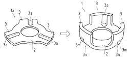
図1に示すごとく、円板状のキャリヤ本体2に複数の舌片状の脚部3・3・3を設けた板金素材1aを用意し、該板金素材1aの前記キャリヤ本体2の部分を、ダイス10の本体挿入穴11内にポンチ20にて圧入する。前記ポンチ20は、図示せぬ油圧装置等のアクチュエータにより動作される。
そして、図2に示すごとく、前記ポンチ20の圧入の際に前記脚部3・3・3がほぼ90度折り曲げられて、キャリヤ1が成形される。また、前記脚部3・3・3の内側には、それぞれ溝3a・3a・3aが形成される。
As shown in FIG. 1, a
As shown in FIG. 2, when the
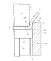
そして、本実施例では、図3乃至図5に示すごとく、前記脚部3の屈折成形前において、板金素材1aの前記脚部3の屈折方向とは逆側の表面1m(うら面)における、前記脚部3の屈折成形後に前記脚部3の根元部3nとなる位置には、前記表面1mから前記脚部3の屈折方向とは逆側の方向に膨出する膨出部3mが設けられ、前記膨出部3mの形状は、前記脚部3の屈折成形後において前記膨出部3mに求められる外側R寸法に応じて設定される構成としている。
And in this example, as shown in FIGS. 3 to 5, before the refraction molding of the
つまり、脚部3の屈折成形前において、脚部3の根元部3nとなる位置に膨出部3mを形成しておくことによれば、該膨出部3mは、脚部3の屈折成形後において、根元部3nの最も外側の部位を構成することになるため、脚部3の屈折成形前の膨出部3mの形状によって、脚部3の屈折成形後の膨出部3mの外側R寸法31が設定されるのである。
尚、この場合、根元部3nにおける膨出部3m以外の部位の外側R寸法32は、外側R寸法31と比較して大きく構成されることになる。
That is, by forming the bulging
In this case, the
また、上記のように、脚部3の屈折成形前における膨出部3mの形状(変形前形状)は、脚部3の屈折成形後における膨出部3mの形状(変形後形状)をどのような形状に設定したいかによって決められるものであり、例えば、前記外側R寸法31をより小さい値に設定したいのであれば、膨出部3mの膨出高さH(図4参照)をより高く設定すればよいことになる。
Further, as described above, the shape of the bulged
また、図5に示すごとく、脚部3の屈折成形後における膨出部3mの形状(変形後形状)において、垂直面3fが構成されるようにすれば、該垂直面3fを他部材を安定して固定する場合の設置面として利用することもできる。また、該垂直面3fから、横方向にキリ孔3hを加工し、該キリ孔3hに前記他部材の一部を送入し、該他部材を固定する構成としてもよい。また、このキリ孔3hの加工の際にも、垂直面3fが構成されていることから、一般的な穿鑿装置により、容易、かつ、正確な孔加工を行うことができる。
Further, as shown in FIG. 5, if the
また、図3乃至図5では、前記脚部3・3・3にそれぞれ設けられる溝3a・3a・3aに対応する位置に、前記膨出部3m・3m・3mを設け、脚部3・3・3の屈折成形後に、その根元部3n・3n・3nに外側R寸法31で構成される部位(極小R部)が設けられることとしたが、前記膨出部3m・3m・3mの形状、配置については、この例に限定されるものではない。例えば、円環状の膨出部3eを設けることによれば、根元部3nの全範囲において、前記外側R寸法31で構成される極小R部を構成することができる。
3 to 5, the bulging
また、以上に述べた膨出部3mは、図4に示すごとく、脚部3の屈折成形前において予め板金素材1aに成形されるものである。この膨出部3mの成形は、例えば、該板金素材1aの上側の表面1dに板厚方向に荷重をかけることで、材料を脚部3の屈折方向とは逆方向(下方)へと寄せ、板金素材1aの下側の表面1m(うら面)から膨出させる、いわゆる潰し加工によって成形することが可能である。
Further, as shown in FIG. 4, the bulging
以上のように、本実施例は、板金素材に脚部が屈折成形される成形部品の製造方法であり、板金素材1aの前記脚部3の屈折方向とは逆側の表面1mにおける、前記脚部3の屈折成形後に前記脚部3の根元部3nとなる位置に、前記表面1mから前記脚部3の屈折方向とは逆側の方向に膨出する膨出部3mを成形する第一の工程と、前記膨出部3mの成形後に、前記脚部3を屈折成形する第二の工程とを有する製造方法とするものである。
As described above, the present embodiment is a method of manufacturing a molded part in which a leg portion is refractively formed on a sheet metal material, and the leg on the
そして、この製造方法によれば、脚部3の屈折成形後における前記膨出部3mの外側R寸法31は、脚部3の屈折成形前における前記膨出部3mの形状によって設定することが可能であり、前記脚部3の肉厚t(図4参照)と無関係に、根元部3n(膨出部3m)の外側R寸法31を所望の値に設定することができる。また、上述したように、本実施例においては、外側R寸法31の極小R部を形成することができる。また、据え込み工法を用いずに極小R部を形成することができるので、折り込み欠陥の発生といった不具合もない。
According to this manufacturing method, the
本実施例では、図1、図6乃至図9に示すごとく、本実施例は、円板状の本体(キャリヤ本体2)に複数の舌片状の脚部3・3・3を設けた板金素材1aの前記本体の部分を、ダイス10の本体挿入穴11内にポンチ20にて圧入することで、前記脚部3を屈折成形させる、板金素材1aに脚部3・3・3が屈折成形される部品の製造方法であって、前記ダイス10には、前記脚部3の屈折成形時に、前記ポンチ20の外周面20Aとの間で、前記脚部3・3・3をそれぞれ収容する脚部収容溝12・12・12が設けられており、前記脚部収容溝12・12・12の深さDは、前記脚部3・3・3の肉厚tと略同一に設定され、前記脚部収容溝12・12・12の周長W(周方向の幅)は、前記ポンチ20の圧入方向に深くなるに従って、狭くなるように設定される構成としている。
そして、前記板金素材1aは、前記脚部3・3・3が前記脚部収容溝12・12・12に収容されつつ、前記ポンチ20によって前記ダイス10の本体挿入穴11内に圧入されるとともに、前記ポンチ20の圧入の進行にともなって、前記脚部3・3・3の根元部3nに材料が寄せられて、外側R寸法41(図9参照)の極小化が進行されることとしている。
このように、本実施例では、前記脚部収容溝12の形状によって、根元部3nに材料の寄りを発生させ、外側R寸法41の極小化を図ることとするものである。
In this embodiment, as shown in FIGS. 1 and 6 to 9, this embodiment is a sheet metal in which a plurality of tongue-shaped
The
As described above, in this embodiment, the shape of the
図6に示すごとく、前記脚部収容溝12について、ダイス10の上面10aから所定の深さEの範囲は、側面視において所定の勾配Cを形成する第一の溝側面12a・12aを有し、前記所定の深さEよりも深い範囲は、側面視において略直線状の第二の溝側面12b・12bを有し、前記脚部収容溝12は、前記第一・第二の溝側面12a・12bにより、側面視において略「Y」字状に構成されている。また、第一の溝側面12a・12aが構成される脚部収容溝12の範囲には内側面12Aが構成され、第二の溝側面12b・12bが構成される脚部収容溝12の範囲を内側面12Bが構成される。
As shown in FIG. 6, the range of the predetermined depth E from the
また、図6及び図7に示すごとく、前記内周面12Aの上端部(ダイス10の上面10aに開口される部位)の周長W(対向し合う第一の溝側面12a・12a間の周長)は、屈折成形前における脚部3の周長とほぼ同一に設定される。また、前記内周面12Bの周長3W(対向し合う第二の溝側面12b・12b間の周長)は、屈折成形後における脚部3の周長とほぼ同一に設定されることとしている。
Further, as shown in FIGS. 6 and 7, the circumferential length W (the circumference between the first groove side surfaces 12a and 12a facing each other) of the upper end portion of the inner
以上の構成において、図8に示すごとく、ポンチ20と押え側ポンチ21にて板金素材1aを挟持しつつ、板金素材1aをダイス10内に圧入させると、前記脚部3は、その両側面が前記脚部収容溝12の第一の溝側面12a・12aの間に挟まれ、圧縮されつつダイス10内へと進行される。この第一の溝側面12a・12aによる脚部3の両側面の圧縮により、脚部3の材料は、脚部3の根元部3nへと寄せられ、押え側ポンチ21と根元部3nと内側面12Aで挟まれる構成される空間40内へと、材料が膨出されることになる。つまり、材料の逃げ場がないため、圧縮された材料は、前記空間40内へと逃げることになり、材料の寄りが進行する。
そして、このようにして、空間40内へ材料が進行することにより、図9に示すごとく、外側R寸法41の極小化が図られることになる。尚、図における外側R寸法42は、前記第一の溝側面12a・12aに勾配Cを設けない場合での根元部3nの形状を示すものである。
In the above configuration, as shown in FIG. 8, when the
Then, as the material advances into the
また、以上の構成において、前記周長W・3W、所定の深さD、及び、所定の勾配Cについては、屈折成形後の脚部3の形状に応じて適宜設定されるものであり、例えば、前記勾配Cを大きく設定することによれば、材料の寄りを多く発生させることができ(変形量を多くすることができる)、前記空間40内への材料の膨出を大きくすることができ、前記外側R寸法41のさらなる極小化を図ることができる。
Further, in the above configuration, the circumferential length W · 3W, the predetermined depth D, and the predetermined gradient C are appropriately set according to the shape of the
また、前記ポンチ20の外周面20Aと、前記ダイス10の本体挿入穴11の内周面11Aの間には、極小の隙間を確保することにとどめ、ポンチ20が本体挿入穴11内にて摺動させる構成とし、前記脚部3の屈折成形の際において、脚部3の材料が前記隙間に逃れることがないようにしている。また、このようにポンチ20とダイス10の間の隙間への材料の逃げを防止することによれば、前記脚部3は、脚部収容溝12内でしか変形することができなくなるため、前記空間40内へ材料の逃げを進行させることができる。そして、これによれば、前記外側R寸法41の極小化を確実に図ることができる。
Further, a minimum gap is ensured between the outer
また、以上に構成したポンチ20と、前記ポンチ20が挿入されるダイス10を備えた製造装置を構成することによれば、外側R寸法を極小とする部品を製造することができる。
Moreover, according to the manufacturing apparatus provided with the
1a 板金素材
3 脚部
3m 膨出部
3n 根元部
31 外側R寸法
1a
Claims (3)
前記ダイスには、前記脚部の屈折成形時に、前記ポンチの外周面との間で、前記脚部をそれぞれ収容する脚部収容溝が設けられており、
前記脚部収容溝の深さは、前記脚部の肉厚と略同一に設定され、
前記脚部収容溝の周長は、前記ポンチの圧入方向に深くなるに従って、狭くなるように設定され、
前記ポンチによる板金素材の前記ダイスへの圧入の進行に伴って、前記脚部の両側面が圧縮されて、前記脚部の材料が該脚部の根元部へと寄せられる、
成形部品の製造方法。 A part of a sheet metal material provided with a plurality of tongue-like leg portions on a plate-like main body is press-fitted into the body insertion hole of the die with a punch, thereby refraction-molding the leg portion. A manufacturing method comprising:
The die is provided with leg receiving grooves for receiving the leg portions between the outer peripheral surface of the punch and the outer peripheral surface of the punch during refraction molding of the leg portions,
The depth of the leg receiving groove is set to be substantially the same as the thickness of the leg,
The circumferential length of the leg portion receiving groove is set to become narrower as it becomes deeper in the press-fitting direction of the punch,
With the progress of press-fitting of the sheet metal material into the die by the punch, both side surfaces of the leg portion are compressed, and the material of the leg portion is brought close to the base portion of the leg portion.
Manufacturing method of molded parts.
板状の本体に複数の舌片状の脚部を設けた板金素材の前記本体の部分を、前記ダイスの本体挿入穴内に前記ポンチにて圧入することで、前記脚部を屈折成形させる、成形部品の製造装置であって、
前記ダイスには、前記脚部の屈折成形時に、前記ポンチの外周面との間で、前記脚部をそれぞれ収容する脚部収容溝が設けられており、
前記脚部収容溝の深さは、前記脚部の肉厚と略同一に設定され、
前記脚部収容溝の周長は、前記ポンチの圧入方向に深くなるに従って、狭くなるように設定され、
前記ポンチによる板金素材の前記ダイスへの圧入の進行に伴って、前記脚部の両側面が圧縮されて、前記脚部の材料が該脚部の根元部へと寄せられる、
成形部品の製造装置。 A punch and a die into which the punch is inserted;
Molding, wherein the leg portion is refractively molded by press-fitting the portion of the sheet metal material provided with a plurality of tongue-like leg portions on the plate-like body into the body insertion hole of the die with the punch. A device for manufacturing parts,
The die is provided with leg receiving grooves for receiving the leg portions between the outer peripheral surface of the punch and the outer peripheral surface of the punch during refraction molding of the leg portions,
The depth of the leg receiving groove is set to be substantially the same as the thickness of the leg,
The circumferential length of the leg portion receiving groove is set to become narrower as it becomes deeper in the press-fitting direction of the punch ,
With the progress of press-fitting of the sheet metal material into the die by the punch, both side surfaces of the leg portion are compressed, and the material of the leg portion is brought close to the base portion of the leg portion.
Molded part manufacturing equipment.
前記ダイスの上面から所定の深さの範囲は、
側面視において所定の勾配を形成する第一の溝側面を有し、
前記所定の深さよりも深い範囲は、
側面視において略直線状の第二の溝側面を有し、
前記脚部収容溝は、前記第一・第二の溝側面により、側面視において略「Y」字状に構成されている、ことを特徴とする、請求項2に記載の成形部品の製造装置。 In the leg receiving groove,
The range of the predetermined depth from the upper surface of the die is
Having a first groove side surface forming a predetermined gradient in a side view;
The range deeper than the predetermined depth is
A second groove side surface that is substantially linear in a side view;
The said leg part accommodation groove | channel is comprised by the said 1st and 2nd groove | channel side surface by the substantially "Y" shape in the side view, The manufacturing apparatus of the molded component of Claim 2 characterized by the above-mentioned. .
Priority Applications (1)
| Application Number | Priority Date | Filing Date | Title |
|---|---|---|---|
| JP2005111111A JP4655732B2 (en) | 2005-04-07 | 2005-04-07 | Molded part manufacturing method, molded part manufacturing apparatus, and molded part |
Applications Claiming Priority (1)
| Application Number | Priority Date | Filing Date | Title |
|---|---|---|---|
| JP2005111111A JP4655732B2 (en) | 2005-04-07 | 2005-04-07 | Molded part manufacturing method, molded part manufacturing apparatus, and molded part |
Publications (2)
| Publication Number | Publication Date |
|---|---|
| JP2006289400A JP2006289400A (en) | 2006-10-26 |
| JP4655732B2 true JP4655732B2 (en) | 2011-03-23 |
Family
ID=37410562
Family Applications (1)
| Application Number | Title | Priority Date | Filing Date |
|---|---|---|---|
| JP2005111111A Expired - Fee Related JP4655732B2 (en) | 2005-04-07 | 2005-04-07 | Molded part manufacturing method, molded part manufacturing apparatus, and molded part |
Country Status (1)
| Country | Link |
|---|---|
| JP (1) | JP4655732B2 (en) |
Families Citing this family (2)
| Publication number | Priority date | Publication date | Assignee | Title |
|---|---|---|---|---|
| US8673479B2 (en) | 2010-03-30 | 2014-03-18 | Samsung Sdi Co., Ltd. | Secondary battery and a secondary battery module |
| WO2014109240A1 (en) | 2013-01-09 | 2014-07-17 | 新日鐵住金株式会社 | Press-forming method |
Citations (2)
| Publication number | Priority date | Publication date | Assignee | Title |
|---|---|---|---|---|
| JP2000288642A (en) * | 1999-04-12 | 2000-10-17 | Toyota Motor Corp | Forming method of bottomed cylindrical container |
| JP2005021955A (en) * | 2003-07-04 | 2005-01-27 | Oota:Kk | Method and device for bending metal plate |
Family Cites Families (2)
| Publication number | Priority date | Publication date | Assignee | Title |
|---|---|---|---|---|
| JPH0252126A (en) * | 1988-08-10 | 1990-02-21 | Kiyouhou Seisakusho:Kk | Manufacture of grooved cylindrical part |
| JP3744562B2 (en) * | 1995-05-09 | 2006-02-15 | ユニプレス株式会社 | Press-formed parts and their processing methods |
-
2005
- 2005-04-07 JP JP2005111111A patent/JP4655732B2/en not_active Expired - Fee Related
Patent Citations (2)
| Publication number | Priority date | Publication date | Assignee | Title |
|---|---|---|---|---|
| JP2000288642A (en) * | 1999-04-12 | 2000-10-17 | Toyota Motor Corp | Forming method of bottomed cylindrical container |
| JP2005021955A (en) * | 2003-07-04 | 2005-01-27 | Oota:Kk | Method and device for bending metal plate |
Also Published As
| Publication number | Publication date |
|---|---|
| JP2006289400A (en) | 2006-10-26 |
Similar Documents
| Publication | Publication Date | Title |
|---|---|---|
| JP5679044B2 (en) | Drive plate manufacturing apparatus and drive plate manufacturing method | |
| JP5636846B2 (en) | Manufacturing method of disc-shaped member with boss and manufacturing device of disc-shaped member with boss | |
| JP4743261B2 (en) | Method for manufacturing roller cage of roller bearing | |
| JP4600432B2 (en) | Press-molded product and method for producing press-molded product | |
| KR20130064133A (en) | Battery case lid and manufacturing method for battery case lid | |
| JP4368394B2 (en) | Clutch gear manufacturing apparatus and clutch gear manufacturing method | |
| JP6071049B2 (en) | Press working method | |
| JP2017196632A (en) | Burring processing device, burring processing method and burring molded part | |
| JP2010120059A (en) | Press formed product, and method and apparatus for manufacturing the same | |
| JP4655732B2 (en) | Molded part manufacturing method, molded part manufacturing apparatus, and molded part | |
| JP2006205232A (en) | Burring method and burring device | |
| JP2019166564A (en) | Joining device and method for manufacturing joint | |
| JP2007289989A (en) | Method and device for manufacturing article having bent part increased in wall thickness | |
| JP2006116593A (en) | Method and apparatus for forming cup-shaped part | |
| JP4972136B2 (en) | Method of stepping an outer peripheral surface of a shaft-shaped member having a circular cross section | |
| JP5039809B2 (en) | Carrier and manufacturing method thereof | |
| JP4353696B2 (en) | Fluid bearing member manufacturing method, fluid bearing member, and hard disk drive | |
| JP2006043719A (en) | Element for continuously variable transmission and method for manufacturing the same | |
| JP5262303B2 (en) | Metal plate press forming method | |
| JP5026850B2 (en) | Workpiece manufacturing method | |
| JP2007098437A (en) | Burring die and burring method | |
| JP3131392U (en) | Screw fixture | |
| JP7342893B2 (en) | Method for joining metal parts and method for manufacturing joined parts | |
| JP7322904B2 (en) | METHOD FOR JOINING METAL PARTS, AND METHOD FOR MANUFACTURING JOINTED PARTS | |
| JP5582769B2 (en) | Manufacturing method of annular parts |
Legal Events
| Date | Code | Title | Description |
|---|---|---|---|
| A621 | Written request for application examination |
Free format text: JAPANESE INTERMEDIATE CODE: A621 Effective date: 20070829 |
|
| A977 | Report on retrieval |
Free format text: JAPANESE INTERMEDIATE CODE: A971007 Effective date: 20090924 |
|
| A131 | Notification of reasons for refusal |
Free format text: JAPANESE INTERMEDIATE CODE: A131 Effective date: 20100720 |
|
| A521 | Written amendment |
Free format text: JAPANESE INTERMEDIATE CODE: A523 Effective date: 20100917 |
|
| TRDD | Decision of grant or rejection written | ||
| A01 | Written decision to grant a patent or to grant a registration (utility model) |
Free format text: JAPANESE INTERMEDIATE CODE: A01 Effective date: 20101130 |
|
| A01 | Written decision to grant a patent or to grant a registration (utility model) |
Free format text: JAPANESE INTERMEDIATE CODE: A01 |
|
| A61 | First payment of annual fees (during grant procedure) |
Free format text: JAPANESE INTERMEDIATE CODE: A61 Effective date: 20101213 |
|
| FPAY | Renewal fee payment (event date is renewal date of database) |
Free format text: PAYMENT UNTIL: 20140107 Year of fee payment: 3 |
|
| R151 | Written notification of patent or utility model registration |
Ref document number: 4655732 Country of ref document: JP Free format text: JAPANESE INTERMEDIATE CODE: R151 |
|
| FPAY | Renewal fee payment (event date is renewal date of database) |
Free format text: PAYMENT UNTIL: 20140107 Year of fee payment: 3 |
|
| LAPS | Cancellation because of no payment of annual fees |