WO2021044754A1 - 画像処理装置、放射線撮像システム、画像処理方法及びプログラム - Google Patents
画像処理装置、放射線撮像システム、画像処理方法及びプログラム Download PDFInfo
- Publication number
- WO2021044754A1 WO2021044754A1 PCT/JP2020/028194 JP2020028194W WO2021044754A1 WO 2021044754 A1 WO2021044754 A1 WO 2021044754A1 JP 2020028194 W JP2020028194 W JP 2020028194W WO 2021044754 A1 WO2021044754 A1 WO 2021044754A1
- Authority
- WO
- WIPO (PCT)
- Prior art keywords
- image
- thickness
- substance
- energy
- radiation
- Prior art date
- Legal status (The legal status is an assumption and is not a legal conclusion. Google has not performed a legal analysis and makes no representation as to the accuracy of the status listed.)
- Ceased
Links
Images


Classifications
-
- A—HUMAN NECESSITIES
- A61—MEDICAL OR VETERINARY SCIENCE; HYGIENE
- A61B—DIAGNOSIS; SURGERY; IDENTIFICATION
- A61B6/00—Apparatus or devices for radiation diagnosis; Apparatus or devices for radiation diagnosis combined with radiation therapy equipment
- A61B6/48—Diagnostic techniques
- A61B6/482—Diagnostic techniques involving multiple energy imaging
-
- A—HUMAN NECESSITIES
- A61—MEDICAL OR VETERINARY SCIENCE; HYGIENE
- A61B—DIAGNOSIS; SURGERY; IDENTIFICATION
- A61B6/00—Apparatus or devices for radiation diagnosis; Apparatus or devices for radiation diagnosis combined with radiation therapy equipment
- A61B6/40—Arrangements for generating radiation specially adapted for radiation diagnosis
- A61B6/4035—Arrangements for generating radiation specially adapted for radiation diagnosis the source being combined with a filter or grating
- A61B6/4042—K-edge filters
-
- A—HUMAN NECESSITIES
- A61—MEDICAL OR VETERINARY SCIENCE; HYGIENE
- A61B—DIAGNOSIS; SURGERY; IDENTIFICATION
- A61B6/00—Apparatus or devices for radiation diagnosis; Apparatus or devices for radiation diagnosis combined with radiation therapy equipment
- A61B6/40—Arrangements for generating radiation specially adapted for radiation diagnosis
- A61B6/405—Source units specially adapted to modify characteristics of the beam during the data acquisition process
-
- A—HUMAN NECESSITIES
- A61—MEDICAL OR VETERINARY SCIENCE; HYGIENE
- A61B—DIAGNOSIS; SURGERY; IDENTIFICATION
- A61B6/00—Apparatus or devices for radiation diagnosis; Apparatus or devices for radiation diagnosis combined with radiation therapy equipment
- A61B6/42—Arrangements for detecting radiation specially adapted for radiation diagnosis
- A61B6/4208—Arrangements for detecting radiation specially adapted for radiation diagnosis characterised by using a particular type of detector
- A61B6/4233—Arrangements for detecting radiation specially adapted for radiation diagnosis characterised by using a particular type of detector using matrix detectors
-
- A—HUMAN NECESSITIES
- A61—MEDICAL OR VETERINARY SCIENCE; HYGIENE
- A61B—DIAGNOSIS; SURGERY; IDENTIFICATION
- A61B6/00—Apparatus or devices for radiation diagnosis; Apparatus or devices for radiation diagnosis combined with radiation therapy equipment
- A61B6/42—Arrangements for detecting radiation specially adapted for radiation diagnosis
- A61B6/4208—Arrangements for detecting radiation specially adapted for radiation diagnosis characterised by using a particular type of detector
- A61B6/4241—Arrangements for detecting radiation specially adapted for radiation diagnosis characterised by using a particular type of detector using energy resolving detectors, e.g. photon counting
-
- A—HUMAN NECESSITIES
- A61—MEDICAL OR VETERINARY SCIENCE; HYGIENE
- A61B—DIAGNOSIS; SURGERY; IDENTIFICATION
- A61B6/00—Apparatus or devices for radiation diagnosis; Apparatus or devices for radiation diagnosis combined with radiation therapy equipment
- A61B6/46—Arrangements for interfacing with the operator or the patient
- A61B6/461—Displaying means of special interest
- A61B6/463—Displaying means of special interest characterised by displaying multiple images or images and diagnostic data on one display
-
- A—HUMAN NECESSITIES
- A61—MEDICAL OR VETERINARY SCIENCE; HYGIENE
- A61B—DIAGNOSIS; SURGERY; IDENTIFICATION
- A61B6/00—Apparatus or devices for radiation diagnosis; Apparatus or devices for radiation diagnosis combined with radiation therapy equipment
- A61B6/48—Diagnostic techniques
- A61B6/481—Diagnostic techniques involving the use of contrast agents
-
- A—HUMAN NECESSITIES
- A61—MEDICAL OR VETERINARY SCIENCE; HYGIENE
- A61B—DIAGNOSIS; SURGERY; IDENTIFICATION
- A61B6/00—Apparatus or devices for radiation diagnosis; Apparatus or devices for radiation diagnosis combined with radiation therapy equipment
- A61B6/50—Apparatus or devices for radiation diagnosis; Apparatus or devices for radiation diagnosis combined with radiation therapy equipment specially adapted for specific body parts; specially adapted for specific clinical applications
- A61B6/505—Apparatus or devices for radiation diagnosis; Apparatus or devices for radiation diagnosis combined with radiation therapy equipment specially adapted for specific body parts; specially adapted for specific clinical applications for diagnosis of bone
-
- A—HUMAN NECESSITIES
- A61—MEDICAL OR VETERINARY SCIENCE; HYGIENE
- A61B—DIAGNOSIS; SURGERY; IDENTIFICATION
- A61B6/00—Apparatus or devices for radiation diagnosis; Apparatus or devices for radiation diagnosis combined with radiation therapy equipment
- A61B6/52—Devices using data or image processing specially adapted for radiation diagnosis
- A61B6/5205—Devices using data or image processing specially adapted for radiation diagnosis involving processing of raw data to produce diagnostic data
-
- A—HUMAN NECESSITIES
- A61—MEDICAL OR VETERINARY SCIENCE; HYGIENE
- A61B—DIAGNOSIS; SURGERY; IDENTIFICATION
- A61B6/00—Apparatus or devices for radiation diagnosis; Apparatus or devices for radiation diagnosis combined with radiation therapy equipment
- A61B6/52—Devices using data or image processing specially adapted for radiation diagnosis
- A61B6/5211—Devices using data or image processing specially adapted for radiation diagnosis involving processing of medical diagnostic data
- A61B6/5217—Devices using data or image processing specially adapted for radiation diagnosis involving processing of medical diagnostic data extracting a diagnostic or physiological parameter from medical diagnostic data
-
- A—HUMAN NECESSITIES
- A61—MEDICAL OR VETERINARY SCIENCE; HYGIENE
- A61B—DIAGNOSIS; SURGERY; IDENTIFICATION
- A61B6/00—Apparatus or devices for radiation diagnosis; Apparatus or devices for radiation diagnosis combined with radiation therapy equipment
- A61B6/52—Devices using data or image processing specially adapted for radiation diagnosis
- A61B6/5211—Devices using data or image processing specially adapted for radiation diagnosis involving processing of medical diagnostic data
- A61B6/5229—Devices using data or image processing specially adapted for radiation diagnosis involving processing of medical diagnostic data combining image data of a patient, e.g. combining a functional image with an anatomical image
- A61B6/5235—Devices using data or image processing specially adapted for radiation diagnosis involving processing of medical diagnostic data combining image data of a patient, e.g. combining a functional image with an anatomical image combining images from the same or different ionising radiation imaging techniques, e.g. PET and CT
- A61B6/5241—Devices using data or image processing specially adapted for radiation diagnosis involving processing of medical diagnostic data combining image data of a patient, e.g. combining a functional image with an anatomical image combining images from the same or different ionising radiation imaging techniques, e.g. PET and CT combining overlapping images of the same imaging modality, e.g. by stitching
-
- A—HUMAN NECESSITIES
- A61—MEDICAL OR VETERINARY SCIENCE; HYGIENE
- A61B—DIAGNOSIS; SURGERY; IDENTIFICATION
- A61B6/00—Apparatus or devices for radiation diagnosis; Apparatus or devices for radiation diagnosis combined with radiation therapy equipment
- A61B6/52—Devices using data or image processing specially adapted for radiation diagnosis
- A61B6/5258—Devices using data or image processing specially adapted for radiation diagnosis involving detection or reduction of artifacts or noise
-
- H—ELECTRICITY
- H04—ELECTRIC COMMUNICATION TECHNIQUE
- H04N—PICTORIAL COMMUNICATION, e.g. TELEVISION
- H04N23/00—Cameras or camera modules comprising electronic image sensors; Control thereof
- H04N23/30—Cameras or camera modules comprising electronic image sensors; Control thereof for generating image signals from X-rays
-
- H—ELECTRICITY
- H04—ELECTRIC COMMUNICATION TECHNIQUE
- H04N—PICTORIAL COMMUNICATION, e.g. TELEVISION
- H04N25/00—Circuitry of solid-state image sensors [SSIS]; Control thereof
- H04N25/70—SSIS architectures; Circuits associated therewith
- H04N25/76—Addressed sensors, e.g. MOS or CMOS sensors
- H04N25/77—Pixel circuitry, e.g. memories, A/D converters, pixel amplifiers, shared circuits or shared components
- H04N25/771—Pixel circuitry, e.g. memories, A/D converters, pixel amplifiers, shared circuits or shared components comprising storage means other than floating diffusion
Definitions
- the present invention relates to an image processing apparatus, a radiation imaging system, an image processing method and a program. More specifically, the present invention relates to a radiation imaging device and a radiation imaging system used for still image photography such as general photography in medical diagnosis and moving image photography such as fluoroscopy.
- a radiation imaging device using a plane detector (Flat Panel Detector, hereinafter abbreviated as "FPD") has become widespread as an imaging device used for medical image diagnosis and non-destructive inspection by radiation.
- FPD Planar Detector
- a thickness image of a plurality of substances such as a bone image and a soft tissue image can be obtained from images of a plurality of different radiation energies by irradiating radiation having a different tube voltage. Can be sought.
- Patent Document 1 discloses a technique for improving the image quality of a bone image by smoothing an image of soft tissue and subtracting the image from the accumulated image.
- a contrast medium is injected into a blood vessel, and a medical device such as a catheter or guide wire is inserted into the blood vessel to determine the position of the contrast medium or medical device. Treatment is performed while checking the shape.
- the present invention provides an image processing technique capable of acquiring a substance-separated image with reduced noise by utilizing the continuity of the thickness of the human body.
- the image processing apparatus shows a first substance separation image showing the thickness of the first substance and a thickness of the second substance based on a plurality of radiation images taken with different radiation energies.
- a generation means for generating a second substance-separated image is provided.
- the generation means is characterized in that a thickness image in which the thickness of the first substance and the thickness of the second substance are combined is generated.
- the image processing method is an image processing method for processing a radiographic image.
- Generation that produces a first substance separation image showing the thickness of the first substance and a second substance separation image showing the thickness of the second substance based on a plurality of radiation images taken with different radiation energies.
- the production step is characterized in that a thickness image in which the thickness of the first substance and the thickness of the second substance are combined is generated.
- the accompanying drawings are included in the specification and are used to form a part thereof, show embodiments of the present invention, and explain the principles of the present invention together with the description thereof.
- the figure which shows the configuration example of the X-ray imaging system by 1st Embodiment.
- 11A is a diagram showing the relationship between the X-ray spectrum and energy
- 11B is a diagram showing the relationship between the line attenuation coefficient and energy.
- the radiation in the present invention includes beams having the same or higher energy, for example, X, in addition to ⁇ -rays, ⁇ -rays, ⁇ -rays, etc., which are beams produced by particles (including photons) emitted by radiation decay. Lines, particle rays, cosmic rays, etc. shall also be included.
- X beams having the same or higher energy
- ⁇ -rays, ⁇ -rays, ⁇ -rays, etc. which are beams produced by particles (including photons) emitted by radiation decay. Lines, particle rays, cosmic rays, etc. shall also be included.
- an apparatus using X-rays will be described as an example of radiation. Therefore, in the following, the radiation imaging device and the radiation imaging system will be described as an X-ray imaging device and an X-ray imaging system, respectively.
- FIG. 1 is a block diagram showing a configuration example of an X-ray imaging system as an example of a radiation imaging system according to the first embodiment.
- the X-ray imaging system of the first embodiment includes an X-ray generator 101, an X-ray control device 102, an imaging control device 103, and an X-ray imaging device 104.
- the X-ray generator 101 generates X-rays and irradiates the subject with X-rays.
- the X-ray control device 102 controls the generation of X-rays in the X-ray generator 101.
- the image pickup control device 103 has, for example, one or more processors (CPUs) and a memory, and the processors execute a program stored in the memory to acquire an X-ray image and perform image processing. Each process including image processing by the image pickup control device 103 may be realized by dedicated hardware, or may be realized by the cooperation of hardware and software.
- the X-ray imaging apparatus 104 includes a phosphor 105 that converts X-rays into visible light, and a two-dimensional detector 106 that detects visible light.
- the two-dimensional detector is a sensor in which pixels 20 for detecting X-ray quanta are arranged in an array of X columns ⁇ Y rows, and outputs image information.
- the image pickup control device 103 functions as an image processing device that processes a radiation image by the processor described above.
- the acquisition unit 131, the correction unit 132, the signal processing unit 133, and the image processing unit 134 show an example of a functional configuration as an image processing device.
- the acquisition unit 131 acquires a plurality of radiation images having different energies obtained by irradiating the subject with radiation and taking a picture.
- the acquisition unit 131 acquires the radiation images obtained by performing a plurality of sample holds during the exposure of one shot of radiation as a plurality of radiation images.
- the correction unit 132 corrects a plurality of radiation images acquired by the acquisition unit 131 to generate a plurality of images used in the energy subtraction process.
- the signal processing unit 133 generates a substance characteristic image using a plurality of images generated by the correction unit 132.
- the substance property image is an image acquired in the energy subtraction process, such as a substance separation image showing the substance separated, such as bone and soft tissue, and a substance identification image showing the effective atomic number and its surface density.
- the signal processing unit 133 has a first substance separation image showing the thickness of the first substance and a second substance separation showing the thickness of the second substance based on a plurality of radiation images taken with different radiation energies. Generate an image.
- the signal processing unit 133 generates a thickness image in which the thickness of the first substance and the thickness of the second substance are combined.
- the first substance contains at least calcium, hydroxyapatite, or bone
- the second substance contains at least water, or a soft substance containing no fat or calcium.
- the details of the signal processing unit 133 will be described later.
- the image processing unit 134 generates a display image using the substance property image acquired by signal processing.
- FIG. 2 is an equivalent circuit diagram of the pixel 20 according to the first embodiment.
- the pixel 20 includes a photoelectric conversion element 201 and an output circuit unit 202.
- the photoelectric conversion element 201 can typically be a photodiode.
- the output circuit unit 202 includes an amplifier circuit unit 204, a clamp circuit unit 206, a sample hold circuit 207, and a selection circuit unit 208.
- the photoelectric conversion element 201 includes a charge storage unit, and the charge storage unit is connected to the gate of the MOS transistor 204a of the amplifier circuit unit 204.
- the source of the MOS transistor 204a is connected to the current source 204c via the MOS transistor 204b.
- a source follower circuit is composed of a MOS transistor 204a and a current source 204c.
- the MOS transistor 204b is an enable switch that turns on when the enable signal EN supplied to the gate reaches an active level to put the source follower circuit into an operating state.
- the charge storage unit of the photoelectric conversion element 201 and the gate of the MOS transistor 204a form a common node, and this node converts the charge stored in the charge storage unit into a voltage.
- Functions as a conversion unit. That is, in the charge-voltage conversion unit, a voltage V ( Q / C) determined by the charge Q stored in the charge storage unit and the capacitance value C possessed by the charge-voltage conversion unit appears.
- the charge-voltage conversion unit is connected to the reset potential Vres via the reset switch 203.
- the reset signal PRESS becomes the active level, the reset switch 203 is turned on, and the potential of the charge-voltage conversion unit is reset to the reset potential Vres.
- the clamp circuit unit 206 clamps the noise output by the amplifier circuit unit 204 according to the potential of the reset charge-voltage conversion unit by the clamp capacitance 206a. That is, the clamp circuit unit 206 is a circuit for canceling this noise from the signal output from the source follower circuit according to the electric charge generated by the photoelectric conversion in the photoelectric conversion element 201. This noise includes kTC noise at reset. Clamping is performed by setting the clamp signal PCL to the active level and turning on the MOS transistor 206b, and then setting the clamp signal PCL to the inactive level to turn off the MOS transistor 206b. The output side of the clamp capacitance 206a is connected to the gate of the MOS transistor 206c.
- the source of the MOS transistor 206c is connected to the current source 206e via the MOS transistor 206d.
- a source follower circuit is composed of a MOS transistor 206c and a current source 206e.
- the MOS transistor 206d is an enable switch that turns on when the enable signal EN0 supplied to the gate reaches the active level to put the source follower circuit into an operating state.
- the signal output from the clamp circuit unit 206 according to the electric charge generated by the photoelectric conversion in the photoelectric conversion element 201 is written as an optical signal in the capacitance 207Sb via the switch 207Sa when the optical signal sampling signal TS becomes an active level. Is done.
- the signal output from the clamp circuit unit 206 when the MOS transistor 206b is turned on immediately after the potential of the charge-voltage conversion unit is reset is the clamp voltage.
- the noise signal is written to the capacitance 207Nb via the switch 207Na when the noise sampling signal TN becomes the active level. This noise signal includes an offset component of the clamp circuit unit 206.
- the switch 207Sa and the capacitance 207Sb form the signal sample hold circuit 207S
- the switch 207Na and the capacitance 207Nb form the noise sample hold circuit 207N.
- the sample hold circuit unit 207 includes a signal sample hold circuit 207S and a noise sample hold circuit 207N.
- the drive circuit unit drives the row selection signal to the active level
- the signal (optical signal) held in the capacitance 207Sb is output to the signal line 21S via the MOS transistor 208Sa and the row selection switch 208Sb.
- the signal (noise) held in the capacitance 207Nb is output to the signal line 21N via the MOS transistor 208Na and the row selection switch 208Nb.
- the MOS transistor 208Sa constitutes a constant current source (not shown) and a source follower circuit provided on the signal line 21S.
- the MOS transistor 208Na constitutes a constant current source (not shown) and a source follower circuit provided on the signal line 21N.
- the MOS transistor 208Sa and the row selection switch 208Sb form the signal selection circuit unit 208S
- the MOS transistor 208Na and the row selection switch 208Nb form the noise selection circuit unit 208N.
- the selection circuit unit 208 includes a signal selection circuit unit 208S and a noise selection circuit unit 208N.
- Pixel 20 may have an addition switch 209S that adds optical signals of a plurality of adjacent pixels 20.
- the addition mode signal ADD becomes the active level and the addition switch 209S is turned on.
- the capacitances 207Sb of the adjacent pixels 20 are connected to each other by the addition switch 209S, and the optical signals are averaged.
- the pixel 20 may have an addition switch 209N that adds noise from a plurality of adjacent pixels 20. When the addition switch 209N is turned on, the capacitance 207Nb of the adjacent pixels 20 is connected to each other by the addition switch 209N, and the noise is averaged.
- the addition unit 209 includes an addition switch 209S and an addition switch 209N.
- the pixel 20 may have a sensitivity changing unit 205 for changing the sensitivity.
- the pixel 20 may include, for example, a first sensitivity change switch 205a and a second sensitivity change switch 205'a, and circuit elements associated thereto.
- the first change signal WIDE reaches the active level
- the first sensitivity change switch 205a is turned on, and the capacitance value of the first additional capacitance 205b is added to the capacitance value of the charge-voltage conversion unit. This reduces the sensitivity of the pixel 20.
- the second change signal WIDE2 becomes the active level, the second sensitivity change switch 205'a is turned on, and the capacity value of the second additional capacity 205'b is added to the capacity value of the charge-voltage conversion unit.
- the enable signal ENw may be set to the active level, and the MOS transistor 204'a may be operated as a source follower instead of the MOS transistor 204a.
- the X-ray image pickup device 104 reads out the output of the pixel circuit as described above from the two-dimensional detector 106, converts it into a digital value with an AD converter (not shown), and then transfers the image to the image pickup control device 103.
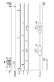
- FIG. 3 shows the drive timing of the X-ray imaging apparatus 104 in the case of obtaining a plurality of X-ray images having different energies for providing to energy subtraction in the X-ray imaging system according to the first embodiment.
- the waveform in FIG. 3 shows the timing of X-ray exposure, synchronization signal, reset of photoelectric conversion element 201, sample hold circuit 207, and reading of an image from signal line 21 with the horizontal axis as time.
- the X-ray tube voltage is ideally a square wave, but it takes a finite amount of time for the tube voltage to rise and fall. In particular, when the exposure time is short with pulsed X-rays, the tube voltage is no longer regarded as a square wave, but has a waveform as shown in X-rays 301 to 303.
- the X-ray energy is different between the X-ray 301 in the rising period, the X-ray 302 in the stable period, and the X-ray 303 in the falling period. Therefore, by obtaining an X-ray image corresponding to the radiation during the period separated by the sample hold, a plurality of types of X-ray images having different energies can be obtained.
- the X-ray imaging apparatus 104 samples with the noise sample hold circuit 207N after the X-ray 301 in the rising period is exposed, and further samples with the signal sample hold circuit 207S after the X-ray 302 in the stable period is exposed. I do. After that, the X-ray imaging apparatus 104 reads out the difference between the signal line 21N and the signal line 21S as an image. At this time, the noise sample hold circuit 207N holds the signal (R 1 ) of the rising X-ray 301, and the signal sample hold circuit 207S holds the signal of the rising X-ray 301 and the signal of the stable X-ray 302. The sum of (B) (R 1 + B) is retained. Therefore, the image 304 corresponding to the signal of the X-ray 302 in the stable period is read out.
- the X-ray imaging apparatus 104 performs sampling again with the signal sample hold circuit 207S after the exposure of the X-ray 303 in the falling period and the reading of the image 304 are completed.
- the X-ray imaging apparatus 104 resets the photoelectric conversion element 201, samples again with the noise sample hold circuit 207N, and reads out the difference between the signal line 21N and the signal line 21S as an image.
- the noise sample hold circuit 207N holds the signal in the state where the X-rays are not exposed
- the signal sample hold circuit 207S holds the signal of the X-ray 301 in the rising period, the X-ray 302 in the stable period, and the falling edge.
- the sum (R 1 + B + R 2 ) of the signal (R 2 ) of the X-ray 303 of the period is held. Therefore, the image 306 corresponding to the signal of the X-ray 301 in the rising period, the signal of the X-ray 302 in the stable period, and the signal of the X-ray 303 in the falling period is read out. Then, by calculating the difference between the image 306 and the image 304, the image 305 corresponding to the sum of the X-rays 301 in the rising period and the X-rays 303 in the falling period can be obtained. This calculation may be performed by the X-ray imaging device 104 or the imaging control device 103.
- the timing for resetting the sample hold circuit 207 and the photoelectric conversion element 201 is determined by using a synchronization signal 307 indicating that X-ray exposure has been started from the X-ray generator 101.
- a configuration can be used in which the tube current of the X-ray generator 101 is measured and it is determined whether or not the current value exceeds a preset threshold value. It is not limited. For example, after the reset of the photoelectric conversion element 201 is completed, the pixel 20 is repeatedly read out, and it is determined whether or not the pixel value exceeds a preset threshold value to detect the start of X-ray exposure. May be reset.
- the X-ray imaging apparatus 104 incorporates an X-ray detector different from the two-dimensional detector 106, and X-ray exposure is determined by determining whether or not the measured value exceeds a preset threshold value.
- a configuration that detects the start may be used. In either method, after a predetermined time has elapsed from the input of the synchronization signal 307 indicating the start of X-ray exposure, sampling of the signal sample hold circuit 207S, sampling of the noise sample hold circuit 207N, and photoelectric conversion element 201 Is reset.
- the image 304 corresponding to the stable period of the pulse X-ray and the image 305 corresponding to the sum of the rising period and the falling period can be obtained. Since the energies of the X-rays exposed when forming these two X-ray images are different from each other, the energy subtraction process can be performed by performing an operation between these X-ray images.
- FIG. 4 shows a drive timing of an X-ray imaging apparatus 104 different from that of FIG. 3 for obtaining a plurality of X-ray images having different energies for providing to energy subtraction in the X-ray imaging system according to the first embodiment. .. It differs from FIG. 3 in that the tube voltage of the X-ray generator 101 is actively switched.
- the X-ray generator 101 exposes the low-energy X-ray 401.
- the X-ray imaging apparatus 104 performs sampling by the noise sample hold circuit 207N.
- the X-ray generator 101 switches the tube voltage to expose the high-energy X-ray 402.
- the X-ray imaging apparatus 104 performs sampling by the signal sample hold circuit 207S.
- the X-ray generator 101 switches the tube voltage to expose the low-energy X-ray 403.
- the X-ray imaging apparatus 104 reads out the difference between the signal line 21N and the signal line 21S as an image.
- the noise sample hold circuit 207N holds the low-energy X-ray 401 signal (R 1 ), and the signal sample-hold circuit 207S holds the low-energy X-ray 401 signal and the high-energy X-ray 402 signal.
- the sum of (B) (R 1 + B) is retained. Therefore, the image 404 corresponding to the high-energy X-ray 402 signal is read out.
- the X-ray imaging apparatus 104 performs sampling again with the signal sample hold circuit 207S after the exposure of the low-energy X-ray 403 and the reading of the image 404 are completed. After that, the X-ray imaging apparatus 104 resets the photoelectric conversion element 201, samples again with the noise sample hold circuit 207N, and reads out the difference between the signal line 21N and the signal line 21S as an image. At this time, the noise sample hold circuit 207N holds a signal in a state where X-rays are not exposed, and the signal sample hold circuit 207S holds a low-energy X-ray 401 signal, a high-energy X-ray 402, and a low-energy signal.
- the image 405 corresponding to the sum of the low-energy X-ray 401 and the low-energy X-ray 403 can be obtained.
- This calculation may be performed by the X-ray imaging device 104 or the imaging control device 103.
- the synchronization signal 407 is the same as in FIG.
- the energy subtraction processing in the first embodiment is divided into three stages: correction processing by the correction unit 132, signal processing by the signal processing unit 133, and image processing by the image processing unit 134. Each process will be described below.
- the correction process is a process of processing a plurality of radiation images acquired from the X-ray imaging apparatus 104 to generate a plurality of images used in the signal processing described later in the energy subtraction process.
- FIG. 5 shows a correction process for the energy subtraction process according to the first embodiment.
- the acquisition unit 131 causes the X-ray image pickup apparatus 104 to perform imaging in a state where X-rays are not exposed, and acquires an image by the drive shown in FIG. 3 or FIG. By this drive, two images are read out.
- the first image image 304 or image 404
- the second image image 306 or image 406
- F_EVEN the second image
- F_ODD and F_EVEN are images corresponding to fixed pattern noise (FPN: Fixed Pattern Noise) of the X-ray imaging apparatus 104.
- the acquisition unit 131 exposes the X-ray image pickup apparatus 104 to X-rays in the absence of a subject to perform imaging, and outputs the images from the X-ray imaging apparatus 104 by the drive shown in FIG. 3 or FIG. Acquire an image for gain correction.
- the first image for gain correction (image 304 or image 404) is referred to as W_ODD
- the second image for gain correction (image 306 or image 406) is referred to as W_EVEN.
- W_ODD and W_EVEN are images corresponding to the sum of the signals of the FPN and the X-ray of the X-ray imaging apparatus 104.
- the correction unit 132 subtracts F_ODD from W_ODD and F_EVEN from W_EVEN to obtain images WF_ODD and WF_EVEN from which the FPN of the X-ray imaging apparatus 104 has been removed. This is called offset correction.
- WF_ODD is an image corresponding to the X-ray 302 in the stable period
- WF_EVEN is an image corresponding to the sum of the X-ray 301 in the rising period, the X-ray 302 in the stable period, and the X-ray 303 in the falling period. Therefore, the correction unit 132 obtains an image corresponding to the sum of the rising X-ray 301 and the falling X-ray 303 by subtracting the WF_ODD from the WF_EVEN.
- the process of obtaining an image corresponding to X-rays in a specific period divided by a sample hold by subtracting a plurality of images in this way is called color correction.
- the energies of the rising X-rays 301 and the falling X-rays 303 are lower than the energies of the stable X-rays 302. Therefore, by subtracting WF_ODD from WF_EVEN by color correction, a low-energy image W_Low when there is no subject can be obtained. Further, from WF_ODD, a high-energy image W_High when there is no subject can be obtained.
- the acquisition unit 131 exposes the X-ray image pickup apparatus 104 to X-rays in a state where the subject is present to perform imaging, and outputs the image from the X-ray image pickup apparatus 104 by the drive shown in FIG. Get an image.
- two images are read out.
- the first image image 304 or image 404
- the second image image 306 or image 406
- the correction unit 132 obtains a low-energy image X_Low when there is a subject and a high-energy image X_High when there is a subject by performing offset correction and color correction in the same manner as when there is no subject.
- the correction unit 132 divides the low-energy image X_Low when there is a subject by the low-energy image W_Low when there is no subject, so that the image L at the attenuation rate at low energy (hereinafter, “low-energy image L”” is used. Also called). Similarly, the correction unit 132 obtains an image H having an attenuation rate at high energy by dividing the high-energy image X_High when there is a subject by the high-energy image W_High when there is no subject (hereinafter, "high energy”). Also called “image H").
- an image with an attenuation rate is obtained by dividing the image obtained based on the radiation image obtained with the subject by the image obtained based on the radiation image obtained without the subject.
- the process of performing is called gain correction. The above is the description of the correction process by the correction unit 132 of the first embodiment.
- FIG. 6 shows a block diagram of signal processing of energy subtraction processing according to the first embodiment.
- the signal processing unit 133 generates a substance property image using a plurality of images obtained from the correction unit 132.
- the generation of a substance-separated image including an image B of bone thickness and an image S of soft tissue thickness will be described.
- the signal processing unit 133 sets the image B of the bone thickness and the thickness of the soft tissue.
- the energy of X-ray photons is E
- the number of photons in energy E is N (E)
- the thickness in the bone thickness image is B
- the thickness in the soft tissue thickness image is S
- the line attenuation coefficient of bone in energy E is ⁇ .
- the photon number N (E) at the energy E is an X-ray spectrum.
- the X-ray spectrum can be obtained by simulation or actual measurement.
- the linear attenuation coefficient ⁇ B (E) of bone in energy E and the linear attenuation coefficient ⁇ S (E) of soft tissue in energy E can be obtained from databases such as NIST (National Institute of Standards and Technology), respectively. Therefore, according to the equation [Equation 3], it is possible to calculate the thickness B in an arbitrary bone thickness image, the thickness S in a soft tissue thickness image, and the attenuation rate I / I 0 in the X-ray spectrum N (E). It is possible.
- Equation 4 L is a pixel value in a low-energy attenuation rate image
- H is a pixel value in a high-energy attenuation rate image.
- the thickness B in the bone thickness image and the thickness S in the soft tissue thickness image can be obtained.
- the case where the Newton-Raphson method is used will be described here.
- the number of iterations m Newton Raphson method, the m-th thickness B m of the bone after iterations, when the thickness of the soft tissue after the m-th iteration was S m the high energy after the m-th iteration
- the attenuation rate H m and the low energy attenuation rate L m after the mth repetition are expressed by the following equation [Equation 5].
- the bone thickness B m + 1 and the soft tissue thickness S m + 1 after the m + 1th repetition are expressed by the following equation [Equation 7] using the high energy attenuation rate H and the low energy attenuation rate L.
- the inverse matrix of the 2x2 matrix is represented by the following [Equation 8] formula from Cramer's rule, where the determinant is set.
- the difference between the high energy attenuation rate H m after the mth repetition and the measured high energy attenuation rate H approaches 0 as much as possible.
- the bone thickness B m after the m-th repetition converges to the bone thickness B
- the m-th soft tissue thickness S m converges to the soft tissue thickness S.
- the nonlinear simultaneous equations shown in the equation [Equation 4] can be solved.
- the image B of the bone thickness and the image S of the soft tissue thickness were calculated, but the present invention is not limited to such a form.
- the thickness W of water and the thickness I of the contrast medium may be calculated. That is, it may be decomposed into the thicknesses of any two kinds of substances.
- the image of the effective atomic number Z and the image of the surface density D can be obtained from the image L of the attenuation rate at low energy and the image H of the attenuation rate at high energy obtained by the correction shown in FIG. 5 (a). Good.
- the effective atomic number Z is the equivalent atomic number of the mixture
- the surface density D is the product of the density of the subject [g / cm 3 ] and the thickness of the subject [cm].
- the nonlinear simultaneous equations were solved by using the Newton-Raphson method.
- the present invention is not limited to such a form.
- iterative solutions such as the least squares method and the dichotomy method may be used.
- the nonlinear simultaneous equations are solved by the iterative method, but the present invention is not limited to such a form.
- Bone thickness B and soft tissue thickness S with respect to various combinations of high-energy attenuation rate H and low-energy attenuation rate L are obtained in advance to generate a table, and by referring to this table, bone thickness B and bone thickness B and A configuration may be used in which the thickness S of the soft tissue is obtained at high speed.
- FIG. 7 shows a block diagram of image processing of energy subtraction processing according to the first embodiment.
- the image processing unit 134 of the first embodiment generates a display image by performing post-processing on the image B of the bone thickness obtained by the signal processing shown in FIG.
- the image processing unit 134 can use logarithmic conversion, dynamic range compression, or the like.
- the stored image A which is an image of the sum of high energy and low energy
- the stored image A is an image compatible with an image having no energy resolution taken by an existing radiation imaging system.
- the image processing unit 134 can generate the stored image A by multiplying the image H of the attenuation rate at high energy and the image L of the attenuation rate at low energy by a coefficient and adding them.
- the image X_EVEN corresponding to the sum of the X-ray 301 in the rising period, the X-ray 302 in the stable period, and the X-ray 303 in the falling period when there is a subject shown in FIG. 5 is displayed when there is no subject. It may be generated by dividing by the image W_EVEN corresponding to the sum of the X-ray 301 in the rising period, the X-ray 302 in the stable period, and the X-ray 303 in the falling period.
- FIG. 8 is a diagram exemplifying the accumulated image A and the bone image B according to the first embodiment.
- the normal human body is composed only of soft tissues and bones.
- IVR interventional radiology
- a contrast medium is injected into a blood vessel.
- a catheter or guide wire is inserted into the blood vessel, and a stent or coil is placed. IVR is performed while confirming the position and shape of the contrast medium and the medical device. Therefore, the visibility may be improved by separating only the contrast medium or the medical device, or removing the background such as soft tissue or bone.
- an image compatible with a normal radiography imaging system that is, an accumulated image A, displays a contrast medium, a stent, bone, and soft tissue.
- the influence of the soft tissue can be reduced by displaying the bone image B.
- the main component of the contrast medium is iodine
- the main component of the medical device is a metal such as stainless steel. Since all of them have an atomic number larger than that of calcium, which is the main component of bone, bone, a contrast medium, and a medical device are displayed on the bone image B.
- the contrast medium image I has a bone and a contrast medium.
- the medical device was displayed. The same applies even if the tube voltage and filter of low-energy X-rays and high-energy X-rays are changed. That is, the contrast agent and medical device could not be separated from the bone.
- FIG. 9 is a diagram schematically showing a soft tissue image and a thickness image according to the first embodiment.
- the soft tissue image S of the phantom of the limb it was found that the bone could be visually recognized as a decrease in the thickness of the soft tissue. This is because the thickness of the soft tissue is reduced by the thickness of the bone.
- the thickness image T when the sum image of the bone image B and the soft tissue image S, that is, the thickness image T was observed, it was found that the contrast of the bone disappeared and it became invisible. This is because the decrease in soft tissue thickness in the area where the bone is present is offset by adding the bone thickness.
- the signal processing unit 133 generates a thickness image in which the thickness of the first substance and the thickness of the second substance are combined. This makes it possible to generate a noise-reduced substance-separated image.
- FIG. 10 is a diagram exemplifying the accumulated image A and the thickness image T according to the first embodiment.
- the contrast medium When the contrast medium is injected into the limbs, both the bone and the contrast medium are visible in the accumulated image A.
- the contrast of the bone disappears, and only the soft tissue and the contrast medium can be visually recognized. Therefore, improvement in visibility can be expected in situations where the bone is an obstacle when visually recognizing a contrast medium or a medical device.
- the contrast of the bone disappears and the contrast of the contrast medium becomes weak at the same time in the thickness image T, which makes it difficult to see.
- the tube voltage of the low-energy X-ray and the high-energy X-ray shown in FIG. 4 the contrast of the bone disappears and the contrast of the contrast medium becomes weak at the same time in the thickness image T, which makes it difficult to see.
- the tube voltage of the low-energy X-ray and the high-energy X-ray shown in FIG. 4 the contrast of the bone disappears and the contrast of the contrast medium
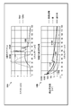
- 11A in FIG. 11 is a diagram showing the relationship between the X-ray spectrum and energy
- 11B in FIG. 11 is a diagram showing the relationship between the line attenuation coefficient and energy.
- the waveform 1101 shows the spectrum of X-rays at a tube voltage of 50 kV
- the waveform 1102 shows the spectrum of X-rays at a tube voltage of 120 kV.
- the broken line 1110 shows the average energy (33 keV) of the X-ray spectrum at a tube voltage of 50 kV
- the broken line 1120 shows the average energy (57 keV) of the X-ray spectrum at a tube voltage of 120 kV.
- the line attenuation coefficient differs for each substance (for example, soft tissue, bone, contrast medium, etc.) and for each energy.
- waveform 1103 shows the line attenuation coefficient of soft tissue
- waveform 1104 shows the line attenuation coefficient of bone
- waveform 1105 shows the line attenuation coefficient of contrast medium.
- the acquisition unit 131 acquires a plurality of radiographic images by performing imaging with the first energy (low energy) and imaging with the second energy (high energy) higher than the first energy.
- the average energy of the radiation spectrum for acquiring a radiation image based on the first energy is lower than the K-edge 1130 of iodine (11B in FIG. 11).
- the tube voltages of low-energy X-rays and high-energy X-rays can be set to, for example, 70 kV and 120 kV.
- iodine which is the main component of the contrast medium, has a K-edge 1130 near 30 keV, for example, as shown in 11B of FIG.
- the contrast of the contrast medium in the thickness image T can be emphasized. That is, by selecting the radiation quality so that the average energy of the radiation spectrum for acquiring a radiation image based on low energy is lower than the K absorption edge of iodine, the contrast agent in the thickness image T The contrast can be emphasized.
- the signal processing unit 133 can set the tube voltage of low-energy X-rays to 40 kV to 50 kV in signal processing and use a quality such as not passing through an additional filter.
- a quality such as not passing through an additional filter.
- the average energy of low-energy X-rays is lower than the K-edge of iodine, and the contrast of the contrast medium is likely to be emphasized.
- the first embodiment of the present invention is suitably used for a portion having a relatively thin thickness and a well-established thickness continuity shown in FIG. 9, such as a limb.
- the accumulated image A, the bone image B, and the thickness image T are displayed as the display image, but the display image is not limited to this example, and the image processing unit 134 displays.
- a high-energy image H or a soft tissue image S may be displayed.
- an image obtained by the timing chart shown in FIG. 4, an image obtained by the correction process shown in FIG. 5, or an image obtained by the signal processing shown in FIG. 6 may be used.
- logarithmic conversion and dynamic range compression have been shown as post-processing for these images, but the present invention is not limited to such an embodiment.
- the image processing unit 134 can perform image processing such as applying a time-direction filter such as a recursive filter or a spatial-direction filter such as a Gaussian filter. That is, it can be said that the image processing in the present embodiment is a process of performing an arbitrary calculation on the image after shooting, correction, or signal processing.
- a time-direction filter such as a recursive filter or a spatial-direction filter such as a Gaussian filter. That is, it can be said that the image processing in the present embodiment is a process of performing an arbitrary calculation on the image after shooting, correction, or signal processing.
- FIG. 12 shows a block diagram of signal processing according to the second embodiment.
- the signal processing unit 133 similarly to the signal processing of FIG. 6, the signal processing unit 133 generates a substance separation image using a plurality of images obtained from the correction unit 132. That is, the signal processing unit 133 generates an image B of the bone thickness and an image S of the soft tissue thickness from the low energy image L and the high energy image H. These thickness images have a problem that the noise becomes larger than that of the low-energy image L and the high-energy image H, and the image quality deteriorates. Therefore, the signal processing unit 133 performs a filter process for the purpose of noise reduction on the image S of the thickness of the soft tissue, and generates an image S'of the thickness of the soft tissue after the filter process.
- the signal processing unit 133 can use a Gaussian filter, a median filter, or the like. Next, the signal processing unit 133 generates the stored image A from the low-energy image L and the high-energy image H in the same manner as described in FIG. 7. Further, the signal processing unit 133 generates a noise-reduced bone thickness image B'from the filtered soft tissue thickness image S'and the accumulated image A.
- soft tissue images do not contain much high-frequency components, so even if noise is removed by filtering, signal components are unlikely to be lost.
- the noise-reduced soft tissue thickness image S'and the noise-reduced accumulated image A it is possible to obtain a noise-reduced bone thickness image B'.
- the soft tissue image contains a high frequency component, there is a problem that a part of the signal component of the image B'of the bone thickness with reduced noise is lost.
- FIG. 13 shows a block diagram of signal processing according to the second embodiment.
- the signal processing unit 133 similarly to the signal processing in the block diagram shown in FIG. 12, the signal processing unit 133 generates a substance separation image using a plurality of images obtained from the correction unit 132. That is, the signal processing unit 133 generates an image B of the bone thickness and an image S of the soft tissue thickness from the low energy image L and the high energy image H. Further, the signal processing unit 133 generates the stored image A from the low energy image L and the high energy image H.
- the signal processing unit 133 generates an image of the sum of the bone thickness image B and the soft tissue thickness image S, that is, the thickness image T. Then, the signal processing unit 133 performs a filter process for the purpose of noise reduction on the thickness image T, and generates a thickness image T'after the filter process. Further, the signal processing unit 133 generates a noise-reduced bone thickness image B'from the filtered thickness image T'and the accumulated image A.
- the bone thickness B is obtained.
- the thickness image T has high continuity, it does not contain a high frequency component more than the image of the thickness of the soft tissue. Therefore, even if the noise is removed by performing the filtering process, the signal component is not easily lost.
- the noise-reduced thickness image T'and the accumulated image A which originally has less noise, a noise-reduced bone thickness image B'can be obtained.
- the signal processing unit 133 uses the first substance separation image (1st substance separation image) based on the thickness image T'after the filter processing and the accumulated image A acquired based on the addition of the plurality of radiation images (H, L). Noise reduction compared to the substance separation image of the first substance (bone thickness image B') or the second substance separation image (soft tissue thickness image S) whose noise is reduced as compared with the bone thickness image B). It is possible to generate a substance-separated image (thickness image S'of the soft tissue) of the second substance.
- the signal processing unit 133 stores the calculation processing result of the formula [Equation 11] in advance in a table of the internal memory, and refers to the table during the calculation processing of the formula [Equation 11] to process the filter. It is possible to acquire the bone thickness image B'(soft tissue thickness image S') corresponding to the later thickness image T'and the accumulated image A. As a result, the signal processing unit 133 can acquire the substance-separated images (B', S') of each substance with reduced noise in a short time not only in the still image shooting but also in the moving image shooting such as IVR. become.
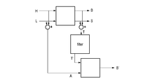
- FIG. 14 shows a block diagram of signal processing according to the third embodiment.
- the signal processing unit 133 similarly to the signal processing of FIG. 13, the signal processing unit 133 generates an image B of the bone thickness and an image S of the soft tissue thickness from the low energy image L and the high energy image H. Further, the signal processing unit 133 generates an image of the sum of the bone thickness image B and the soft tissue thickness image S, that is, the thickness image T. Then, the signal processing unit 133 performs a filter process for removing the contrast of the contrast medium on the thickness image T, and generates a thickness image T'after the filter process. Further, the signal processing unit 133 generates a contrast agent image I'from the thickness image T', the low energy image L, and the high energy image H after the filter processing.
- the bone thickness image in a certain pixel It is possible to obtain the thickness B in the above and the thickness S in the thickness image of the soft part structure.
- the bone disappears but the contrast medium is visible. That is, the thickness changes only in the portion of the blood vessel containing the contrast medium. However, in the portion of the blood vessel containing the contrast agent, the blood is replaced by the contrast agent. That is, the true thickness image T'should not change with or without contrast medium.
- the blood vessel containing the contrast medium is generally thin, it is possible to obtain a true thickness image T'by removing the change in thickness due to the contrast medium by performing a filter treatment such as a Gaussian filter on the thickness image T. it can. That is, if the thickness in the filtered thickness image T'is substituted instead of the thickness image T and the equation [Equation 13] is solved, the bone thickness image B', the soft tissue thickness image S', and the contrast agent A thickness image I'can be obtained.
- a filter treatment such as a Gaussian filter
- the signal processing unit 133 applies a spatial filter to the thickness image T, and based on the filtered thickness image T'and a plurality of radiation images (low energy image L and high energy image H), the first substance Compared with the substance separation image (bone thickness image B') of the first substance and the second substance separation image (soft tissue thickness image S) whose noise is reduced as compared with the separation image (bone thickness image B).
- the noise-reduced substance separation image of the second substance (thickness image S'of the soft tissue) and the thickness of the third substance (contrast agent containing iodine) different from the first substance and the second substance.
- a third substance-separated image is generated.
- the signal processing unit 133 stores the calculation processing result of the formula [Equation 13] in advance in a table of the internal memory, and refers to the table during the calculation processing of the formula [Equation 13] to obtain a filter. Obtained a thickness image T'after processing, a bone thickness image B'corresponding to a plurality of radiographic images (low energy image L and a high energy image H), a soft tissue thickness image S', and a contrast agent thickness image I'. It is also possible to do. As a result, the signal processing unit 133 can acquire the substance separation images (B', S', I') of each substance in a short time as compared with the case of analyzing the nonlinear equation.
- the noise is reduced in the thickness image T'after the filter processing, but the noise is not reduced in the low energy image L and the high energy image H. Therefore, there is a problem that the noise of the bone thickness image B', the soft tissue thickness image S', and the contrast medium thickness image I'is increased, and the image quality is deteriorated.
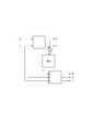
- the signal processing unit 133 can also perform processing.
- the signal processing unit 133 performs a filter process for the purpose of noise reduction on the sum image of the bone thickness image B'and the soft tissue thickness image S', that is, the thickness image t containing no contrast agent, and filters the image.
- a thickness image t'without the subsequent contrast agent is generated.
- the signal processing unit 133 generates the stored image A from the low energy image L and the high energy image H by the same method as described in FIG.
- the signal processing unit 133 includes a filter-processed thickness image T'(first thickness image), a filter-processed thickness image t'(second thickness image) that does not contain a contrast agent, and an accumulated image A. From this, a noise-reduced thickness image I'' of the contrast agent is generated.
- the thickness of the bone in a certain pixel It is possible to obtain the thickness in the image B.
- the thickness image I'' of the contrast medium can be obtained.
- the noise-reduced thickness image T' the noise-reduced thickness image t'without the contrast medium, and the accumulated image A which originally has less noise, the noise-reduced thickness image of the contrast medium is used. I'' can be obtained.
- the signal processing unit 133 has a noise-reduced first substance substance separation image (bone thickness image B') and a noise-reduced second substance substance separation image (soft tissue thickness image S'). ) To generate a second thickness image (thickness image t not containing the contrast agent) that does not contain the third substance (contrast agent containing iodine). Then, the signal processing unit 133 applies the spatial filter to the thickness image T, the first thickness image T'after the filter processing, and applies the spatial filter to the second thickness image t, and the second after the filter processing.
- the noise is reduced as compared with the third substance separation image (thickness image I'of the contrast agent).
- a substance-separated image (thickness image of the contrast agent I'') of the substance of the above is generated.
- the signal processing unit 133 stores the calculation processing result of the formula [Equation 15] in advance in a table of the internal memory, and refers to the table during the calculation processing of the formula [Equation 15] to perform filter processing. It is also possible to acquire the noise-reduced thickness image I'' of the contrast agent corresponding to the later first thickness image T'and the accumulated image A and the second thickness image t'after the filtering. As a result, the signal processing unit 133 can acquire a substance-separated image of the contrast medium with noise reduction in a short time as compared with the case of analyzing the nonlinear equation.
- an indirect X-ray sensor using a phosphor was used as the X-ray imaging apparatus 104.
- the present invention is not limited to such a form.
- a direct type X-ray sensor using a direct conversion material such as CdTe may be used. That is, the X-ray sensor may be either an indirect type or a direct type.
- the tube voltage of the X-ray generator 101 is changed in the operation shown in FIG.
- the present invention is not limited to such a form.
- the energy of the X-rays exposed to the X-ray image pickup device 104 may be changed by switching the filter of the X-ray generator 101 with time. That is, the method for changing the energy of the X-rays exposed to the X-ray imaging apparatus 104 is not limited to any method.
- images of different energies were obtained by changing the energy of X-rays, but the present invention is not limited to such an embodiment.
- images of different energies can be obtained from a two-dimensional detector on the front side and a two-dimensional detector on the back side in the incident direction of X-rays. It may be configured as.
- the energy subtraction process is performed by using the image pickup control device 103 of the X-ray imaging system.
- the present invention is not limited to such a form.
- the image acquired by the image pickup control device 103 may be transferred to another computer to perform energy subtraction processing.
- the acquired image may be transferred to another personal computer via a medical PACS, subjected to energy subtraction processing, and then displayed. That is, the device that performs the correction process described in the above embodiment does not have to be a set with the photographing device (an image viewer may be used).
- this embodiment it is possible to acquire a substance separation image with reduced noise.
- the present invention supplies a program that realizes one or more functions of the above-described embodiment to a system or device via a network or storage medium, and one or more processors in the computer of the system or device reads and executes the program. It can also be realized by the processing to be performed. It can also be realized by a circuit (for example, ASIC) that realizes one or more functions.
- a circuit for example, ASIC
Landscapes
- Health & Medical Sciences (AREA)
- Life Sciences & Earth Sciences (AREA)
- Engineering & Computer Science (AREA)
- Medical Informatics (AREA)
- Physics & Mathematics (AREA)
- Biomedical Technology (AREA)
- Molecular Biology (AREA)
- Biophysics (AREA)
- High Energy & Nuclear Physics (AREA)
- Veterinary Medicine (AREA)
- Nuclear Medicine, Radiotherapy & Molecular Imaging (AREA)
- Optics & Photonics (AREA)
- Pathology (AREA)
- Radiology & Medical Imaging (AREA)
- Public Health (AREA)
- Heart & Thoracic Surgery (AREA)
- General Health & Medical Sciences (AREA)
- Surgery (AREA)
- Animal Behavior & Ethology (AREA)
- Computer Vision & Pattern Recognition (AREA)
- Multimedia (AREA)
- Signal Processing (AREA)
- Mathematical Physics (AREA)
- Human Computer Interaction (AREA)
- Physiology (AREA)
- Orthopedic Medicine & Surgery (AREA)
- Dentistry (AREA)
- Oral & Maxillofacial Surgery (AREA)
- Apparatus For Radiation Diagnosis (AREA)
Priority Applications (2)
| Application Number | Priority Date | Filing Date | Title |
|---|---|---|---|
| EP20859940.7A EP4014874B1 (en) | 2019-09-02 | 2020-07-21 | Image processing device, radiographic imaging system, image processing method, and program |
| US17/652,006 US20220167935A1 (en) | 2019-09-02 | 2022-02-22 | Image processing apparatus, radiation imaging system, image processing method, and non-transitory computer-readable storage medium |
Applications Claiming Priority (2)
| Application Number | Priority Date | Filing Date | Title |
|---|---|---|---|
| JP2019-159726 | 2019-09-02 | ||
| JP2019159726A JP7373323B2 (ja) | 2019-09-02 | 2019-09-02 | 画像処理装置、放射線撮像システム、画像処理方法及びプログラム |
Related Child Applications (1)
| Application Number | Title | Priority Date | Filing Date |
|---|---|---|---|
| US17/652,006 Continuation US20220167935A1 (en) | 2019-09-02 | 2022-02-22 | Image processing apparatus, radiation imaging system, image processing method, and non-transitory computer-readable storage medium |
Publications (1)
| Publication Number | Publication Date |
|---|---|
| WO2021044754A1 true WO2021044754A1 (ja) | 2021-03-11 |
Family
ID=74847574
Family Applications (1)
| Application Number | Title | Priority Date | Filing Date |
|---|---|---|---|
| PCT/JP2020/028194 Ceased WO2021044754A1 (ja) | 2019-09-02 | 2020-07-21 | 画像処理装置、放射線撮像システム、画像処理方法及びプログラム |
Country Status (4)
| Country | Link |
|---|---|
| US (1) | US20220167935A1 (enExample) |
| EP (1) | EP4014874B1 (enExample) |
| JP (1) | JP7373323B2 (enExample) |
| WO (1) | WO2021044754A1 (enExample) |
Families Citing this family (7)
| Publication number | Priority date | Publication date | Assignee | Title |
|---|---|---|---|---|
| JP7619821B2 (ja) | 2021-02-09 | 2025-01-22 | キヤノン株式会社 | 情報処理装置、放射線撮影システム、情報処理方法およびプログラム |
| JP2024025211A (ja) | 2022-08-10 | 2024-02-26 | キヤノン株式会社 | 放射線撮像装置、放射線撮像システム、制御装置、放射線撮像装置の制御方法、および、放射線撮像装置を制御するためのプログラム |
| JP2024086198A (ja) * | 2022-12-16 | 2024-06-27 | キヤノン株式会社 | 放射線撮影装置及びその制御方法、放射線撮影システム、情報処理装置、並びに、プログラム |
| EP4509054A1 (de) * | 2023-08-14 | 2025-02-19 | Siemens Healthineers AG | Verfahren und vorrichtung zur nachbearbeitung von radiogrammen |
| EP4530613A1 (de) * | 2023-09-26 | 2025-04-02 | Siemens Healthineers AG | Verfahren und vorrichtung zum abschätzen von materialdicken in radiologischen projektionsbildern |
| JP2025139125A (ja) * | 2024-03-12 | 2025-09-26 | 富士フイルム株式会社 | 放射線画像処理装置、方法およびプログラム |
| JP2025139126A (ja) * | 2024-03-12 | 2025-09-26 | 富士フイルム株式会社 | 放射線画像処理装置、方法およびプログラム |
Citations (8)
| Publication number | Priority date | Publication date | Assignee | Title |
|---|---|---|---|---|
| JPH03285475A (ja) | 1990-02-14 | 1991-12-16 | Fuji Photo Film Co Ltd | エネルギーサブトラクション画像生成方法 |
| JPH05161633A (ja) * | 1991-12-18 | 1993-06-29 | Toshiba Corp | 放射線診断装置 |
| JP2008229122A (ja) * | 2007-03-22 | 2008-10-02 | Fujifilm Corp | 画像成分分離装置、方法、およびプログラム |
| JP2009078034A (ja) * | 2007-09-27 | 2009-04-16 | Fujifilm Corp | エネルギーサブトラクション用画像生成装置および方法 |
| US20140270064A1 (en) * | 2013-03-12 | 2014-09-18 | Commonwealth Scientific And Industrial Research Organisation | X-ray imaging apparatus and control method for the same |
| WO2014188864A1 (ja) * | 2013-05-24 | 2014-11-27 | 株式会社日立メディコ | X線ct装置、及び処理方法 |
| JP2019110955A (ja) * | 2017-12-20 | 2019-07-11 | キヤノン株式会社 | 放射線撮影システム、情報処理装置、情報処理装置の制御方法、およびプログラム |
| JP2019159726A (ja) | 2018-03-12 | 2019-09-19 | 株式会社リコー | 行動認識装置、行動認識システム、行動認識方法およびプログラム |
Family Cites Families (6)
| Publication number | Priority date | Publication date | Assignee | Title |
|---|---|---|---|---|
| FR2903211B1 (fr) * | 2006-06-30 | 2009-03-06 | Gen Electric | Procedes et dispositifs de correction d'une mammographie a implant et de segmentation d'un implant |
| FR2948481B1 (fr) * | 2009-07-27 | 2012-01-20 | Gen Electric | Procede d'imagerie pour la realisation d'une modelisation en triple energie, et dispositif pour la mise en oeuvre d'un tel procede |
| KR101689866B1 (ko) * | 2010-07-29 | 2016-12-27 | 삼성전자주식회사 | 영상 처리 방법 및 장치와 이를 채용한 의료영상시스템 |
| KR102103419B1 (ko) * | 2013-08-30 | 2020-04-24 | 삼성전자주식회사 | 엑스선 영상 장치 및 그 제어 방법 |
| EP3429474B1 (en) * | 2016-06-07 | 2019-07-10 | Koninklijke Philips N.V. | Improved precision and resolution of quantitative imaging by combining spectral and non-spectral material decomposition |
| JP7054329B2 (ja) * | 2017-10-06 | 2022-04-13 | キヤノン株式会社 | 画像処理装置、画像処理方法及びプログラム |
-
2019
- 2019-09-02 JP JP2019159726A patent/JP7373323B2/ja active Active
-
2020
- 2020-07-21 EP EP20859940.7A patent/EP4014874B1/en active Active
- 2020-07-21 WO PCT/JP2020/028194 patent/WO2021044754A1/ja not_active Ceased
-
2022
- 2022-02-22 US US17/652,006 patent/US20220167935A1/en not_active Abandoned
Patent Citations (8)
| Publication number | Priority date | Publication date | Assignee | Title |
|---|---|---|---|---|
| JPH03285475A (ja) | 1990-02-14 | 1991-12-16 | Fuji Photo Film Co Ltd | エネルギーサブトラクション画像生成方法 |
| JPH05161633A (ja) * | 1991-12-18 | 1993-06-29 | Toshiba Corp | 放射線診断装置 |
| JP2008229122A (ja) * | 2007-03-22 | 2008-10-02 | Fujifilm Corp | 画像成分分離装置、方法、およびプログラム |
| JP2009078034A (ja) * | 2007-09-27 | 2009-04-16 | Fujifilm Corp | エネルギーサブトラクション用画像生成装置および方法 |
| US20140270064A1 (en) * | 2013-03-12 | 2014-09-18 | Commonwealth Scientific And Industrial Research Organisation | X-ray imaging apparatus and control method for the same |
| WO2014188864A1 (ja) * | 2013-05-24 | 2014-11-27 | 株式会社日立メディコ | X線ct装置、及び処理方法 |
| JP2019110955A (ja) * | 2017-12-20 | 2019-07-11 | キヤノン株式会社 | 放射線撮影システム、情報処理装置、情報処理装置の制御方法、およびプログラム |
| JP2019159726A (ja) | 2018-03-12 | 2019-09-19 | 株式会社リコー | 行動認識装置、行動認識システム、行動認識方法およびプログラム |
Also Published As
| Publication number | Publication date |
|---|---|
| EP4014874A4 (en) | 2023-02-22 |
| EP4014874B1 (en) | 2023-12-13 |
| JP7373323B2 (ja) | 2023-11-02 |
| JP2021037031A (ja) | 2021-03-11 |
| EP4014874A1 (en) | 2022-06-22 |
| US20220167935A1 (en) | 2022-06-02 |
Similar Documents
| Publication | Publication Date | Title |
|---|---|---|
| JP7373323B2 (ja) | 画像処理装置、放射線撮像システム、画像処理方法及びプログラム | |
| JP7085043B2 (ja) | 画像処理装置、画像処理方法及びプログラム | |
| JP7352687B2 (ja) | 放射線撮影システム、撮影制御装置及び方法 | |
| JP7161297B2 (ja) | 放射線撮影システム、画像処理装置、撮影制御装置及びその作動方法、プログラム | |
| WO2020250900A1 (ja) | 画像処理装置及び画像処理方法、プログラム | |
| WO2007026419A1 (ja) | 放射線撮像装置および放射線検出信号処理方法 | |
| WO2020095578A1 (ja) | 情報処理装置および方法、放射線撮影システム | |
| WO2022071024A1 (ja) | 画像処理装置、画像処理方法及びプログラム | |
| US12217401B2 (en) | Image processing apparatus, image processing method, and storage medium | |
| JP2020203083A (ja) | 放射線撮像装置及び放射線撮像システム | |
| JP7425619B2 (ja) | 画像処理装置及び画像処理方法 | |
| US20230401677A1 (en) | Image processing apparatus, radiation imaging system, image processing method, and non-transitory computer-readable storage medium | |
| JP7431602B2 (ja) | 画像処理装置及び画像処理方法 | |
| JP2020005918A (ja) | 画像処理装置およびその制御方法 | |
| WO2022181022A1 (ja) | 画像処理装置及び方法、放射線撮像システム、プログラム | |
| JP2022134547A (ja) | 画像処理装置、放射線撮像システム、画像処理方法及びプログラム | |
| JP2025023667A (ja) | 画像処理装置、放射線撮像システム、画像処理方法及びプログラム | |
| JP2009219529A (ja) | 放射線画像撮影装置 | |
| JP2025006434A (ja) | 画像処理装置、放射線撮像システム、画像処理方法及びプログラム | |
| JP2023172296A (ja) | 情報処理装置、情報処理方法およびプログラム |
Legal Events
| Date | Code | Title | Description |
|---|---|---|---|
| 121 | Ep: the epo has been informed by wipo that ep was designated in this application |
Ref document number: 20859940 Country of ref document: EP Kind code of ref document: A1 |
|
| NENP | Non-entry into the national phase |
Ref country code: DE |
|
| ENP | Entry into the national phase |
Ref document number: 2020859940 Country of ref document: EP Effective date: 20220317 |