WO2021039983A1 - 送信装置、送信方法及びプログラム - Google Patents
送信装置、送信方法及びプログラム Download PDFInfo
- Publication number
- WO2021039983A1 WO2021039983A1 PCT/JP2020/032658 JP2020032658W WO2021039983A1 WO 2021039983 A1 WO2021039983 A1 WO 2021039983A1 JP 2020032658 W JP2020032658 W JP 2020032658W WO 2021039983 A1 WO2021039983 A1 WO 2021039983A1
- Authority
- WO
- WIPO (PCT)
- Prior art keywords
- image data
- transmission
- image
- data
- time
- Prior art date
- Legal status (The legal status is an assumption and is not a legal conclusion. Google has not performed a legal analysis and makes no representation as to the accuracy of the status listed.)
- Ceased
Links
Images







Classifications
-
- H—ELECTRICITY
- H04—ELECTRIC COMMUNICATION TECHNIQUE
- H04N—PICTORIAL COMMUNICATION, e.g. TELEVISION
- H04N19/00—Methods or arrangements for coding, decoding, compressing or decompressing digital video signals
- H04N19/10—Methods or arrangements for coding, decoding, compressing or decompressing digital video signals using adaptive coding
- H04N19/102—Methods or arrangements for coding, decoding, compressing or decompressing digital video signals using adaptive coding characterised by the element, parameter or selection affected or controlled by the adaptive coding
- H04N19/103—Selection of coding mode or of prediction mode
- H04N19/107—Selection of coding mode or of prediction mode between spatial and temporal predictive coding, e.g. picture refresh
-
- H—ELECTRICITY
- H04—ELECTRIC COMMUNICATION TECHNIQUE
- H04N—PICTORIAL COMMUNICATION, e.g. TELEVISION
- H04N19/00—Methods or arrangements for coding, decoding, compressing or decompressing digital video signals
- H04N19/10—Methods or arrangements for coding, decoding, compressing or decompressing digital video signals using adaptive coding
- H04N19/102—Methods or arrangements for coding, decoding, compressing or decompressing digital video signals using adaptive coding characterised by the element, parameter or selection affected or controlled by the adaptive coding
- H04N19/103—Selection of coding mode or of prediction mode
- H04N19/105—Selection of the reference unit for prediction within a chosen coding or prediction mode, e.g. adaptive choice of position and number of pixels used for prediction
-
- H—ELECTRICITY
- H04—ELECTRIC COMMUNICATION TECHNIQUE
- H04N—PICTORIAL COMMUNICATION, e.g. TELEVISION
- H04N19/00—Methods or arrangements for coding, decoding, compressing or decompressing digital video signals
- H04N19/10—Methods or arrangements for coding, decoding, compressing or decompressing digital video signals using adaptive coding
- H04N19/134—Methods or arrangements for coding, decoding, compressing or decompressing digital video signals using adaptive coding characterised by the element, parameter or criterion affecting or controlling the adaptive coding
- H04N19/146—Data rate or code amount at the encoder output
-
- H—ELECTRICITY
- H04—ELECTRIC COMMUNICATION TECHNIQUE
- H04N—PICTORIAL COMMUNICATION, e.g. TELEVISION
- H04N19/00—Methods or arrangements for coding, decoding, compressing or decompressing digital video signals
- H04N19/10—Methods or arrangements for coding, decoding, compressing or decompressing digital video signals using adaptive coding
- H04N19/134—Methods or arrangements for coding, decoding, compressing or decompressing digital video signals using adaptive coding characterised by the element, parameter or criterion affecting or controlling the adaptive coding
- H04N19/164—Feedback from the receiver or from the transmission channel
-
- H—ELECTRICITY
- H04—ELECTRIC COMMUNICATION TECHNIQUE
- H04N—PICTORIAL COMMUNICATION, e.g. TELEVISION
- H04N19/00—Methods or arrangements for coding, decoding, compressing or decompressing digital video signals
- H04N19/10—Methods or arrangements for coding, decoding, compressing or decompressing digital video signals using adaptive coding
- H04N19/134—Methods or arrangements for coding, decoding, compressing or decompressing digital video signals using adaptive coding characterised by the element, parameter or criterion affecting or controlling the adaptive coding
- H04N19/164—Feedback from the receiver or from the transmission channel
- H04N19/166—Feedback from the receiver or from the transmission channel concerning the amount of transmission errors, e.g. bit error rate [BER]
-
- H—ELECTRICITY
- H04—ELECTRIC COMMUNICATION TECHNIQUE
- H04N—PICTORIAL COMMUNICATION, e.g. TELEVISION
- H04N19/00—Methods or arrangements for coding, decoding, compressing or decompressing digital video signals
- H04N19/10—Methods or arrangements for coding, decoding, compressing or decompressing digital video signals using adaptive coding
- H04N19/169—Methods or arrangements for coding, decoding, compressing or decompressing digital video signals using adaptive coding characterised by the coding unit, i.e. the structural portion or semantic portion of the video signal being the object or the subject of the adaptive coding
- H04N19/17—Methods or arrangements for coding, decoding, compressing or decompressing digital video signals using adaptive coding characterised by the coding unit, i.e. the structural portion or semantic portion of the video signal being the object or the subject of the adaptive coding the unit being an image region, e.g. an object
- H04N19/172—Methods or arrangements for coding, decoding, compressing or decompressing digital video signals using adaptive coding characterised by the coding unit, i.e. the structural portion or semantic portion of the video signal being the object or the subject of the adaptive coding the unit being an image region, e.g. an object the region being a picture, frame or field
-
- H—ELECTRICITY
- H04—ELECTRIC COMMUNICATION TECHNIQUE
- H04N—PICTORIAL COMMUNICATION, e.g. TELEVISION
- H04N21/00—Selective content distribution, e.g. interactive television or video on demand [VOD]
- H04N21/20—Servers specifically adapted for the distribution of content, e.g. VOD servers; Operations thereof
- H04N21/23—Processing of content or additional data; Elementary server operations; Server middleware
- H04N21/234—Processing of video elementary streams, e.g. splicing of video streams or manipulating encoded video stream scene graphs
- H04N21/2343—Processing of video elementary streams, e.g. splicing of video streams or manipulating encoded video stream scene graphs involving reformatting operations of video signals for distribution or compliance with end-user requests or end-user device requirements
-
- H—ELECTRICITY
- H04—ELECTRIC COMMUNICATION TECHNIQUE
- H04N—PICTORIAL COMMUNICATION, e.g. TELEVISION
- H04N21/00—Selective content distribution, e.g. interactive television or video on demand [VOD]
- H04N21/20—Servers specifically adapted for the distribution of content, e.g. VOD servers; Operations thereof
- H04N21/23—Processing of content or additional data; Elementary server operations; Server middleware
- H04N21/24—Monitoring of processes or resources, e.g. monitoring of server load, available bandwidth, upstream requests
-
- H—ELECTRICITY
- H04—ELECTRIC COMMUNICATION TECHNIQUE
- H04N—PICTORIAL COMMUNICATION, e.g. TELEVISION
- H04N19/00—Methods or arrangements for coding, decoding, compressing or decompressing digital video signals
- H04N19/42—Methods or arrangements for coding, decoding, compressing or decompressing digital video signals characterised by implementation details or hardware specially adapted for video compression or decompression, e.g. dedicated software implementation
- H04N19/436—Methods or arrangements for coding, decoding, compressing or decompressing digital video signals characterised by implementation details or hardware specially adapted for video compression or decompression, e.g. dedicated software implementation using parallelised computational arrangements
Definitions
- the present invention relates to a transmitting device, a transmitting method and a program.
- an image showing the game play status is generated on the cloud server. Then, the image data in which the image is encoded is transmitted from the cloud server to the terminal, and the image obtained by decoding the image data is displayed on the terminal. By repeatedly executing this series of processes, a moving image showing the game play status is displayed on the terminal.
- the size of the image data in which the frame image is encoded is smaller when the frame image is encoded in the P frame which requires the reference destination than when the frame image is encoded in the I frame which does not require the reference destination.
- the image data does not reach the terminal, or part or all of the image data received by the terminal is damaged. May fail to receive.
- the present invention has been made in view of the above circumstances, and one of the objects thereof is a transmission device and a transmission method capable of reducing the number of times of unnecessary transmission of image data due to a failure in receiving the referenced image data. And to provide the program.
- the transmission device has an acquisition unit that acquires a first image drawn in the frame buffer and acquires a second image drawn in the frame buffer, and the first image.
- the encoding processing unit that generates the first image data in which the image of 1 is encoded and generates the second image data in which the second image is encoded, and the first image data are transmitted to the second image.
- the second image includes a transmission unit for transmitting image data and a confirmation unit for confirming the possibility that the transmission of the first image data has failed, and the second image is obtained after transmitting the first image data.
- the encoding processing unit is expected to fail in transmitting the first image data at the timing of encoding the second image.
- it is controlled whether or not to generate the second image data that does not require a reference destination.
- the confirmation unit confirms whether or not the transmission of the first image data is successful, and the encoding processing unit performs the first image by the timing of encoding the second image. Whether or not to generate the second image data that does not require a reference destination is controlled depending on whether or not the successful transmission of the image data of the above is confirmed.
- the confirmation unit is based on whether or not a positive response indicating that the first image data has been successfully received has been received from the terminal that receives the first image data. It may be confirmed whether or not the transmission of the image data is successful.
- the confirmation unit may transmit a transmission failure expected signal, which is transmitted from a terminal that receives the first image data, indicating that reception of the first image data has not been confirmed, and a transmission failure expected signal. Whether or not the transmission of the first image data was successful based on the transmission failure expectation cancellation signal transmitted from the terminal after the transmission of the first image data indicating that the success of the reception of the first image data was confirmed. May be confirmed.
- the encoding processing unit when the success of transmission of the first image data is not confirmed by the timing of encoding the second image, the encoding processing unit requires a reference destination on one side and a reference destination on the other side. A pair of unnecessary second image data is generated, and the transmission unit determines whether or not the success of transmission of the first image data is confirmed by the timing of transmitting the second image data. Therefore, it may be controlled whether to transmit the second image data that requires a reference destination or to transmit the second image data that does not require a reference destination.
- the confirmation unit transmits the first image data even if the time required for determining that the failure to transmit the first image data has timed out has not elapsed. Then, when the given time has elapsed, it is determined that the transmission of the first image data is likely to have failed.
- the given time is a time dynamically determined based on the statistics of the transmission record of the image data.
- the encoding processing unit changes the data rate according to the transmission frequency of image data that does not require a reference destination based on the expectation.
- the transmission method includes a first acquisition step of acquiring a first image drawn in a frame buffer and a first encoding processing step of generating first image data in which the first image is encoded. And the first transmission step of transmitting the first image data, and the second image drawn in the frame buffer for the first time after a predetermined time has elapsed since the transmission of the first image data.
- the transmission of the first image data at the timing of encoding the second image is expected to fail, including the second transmission step of transmitting the second image data.
- it is controlled whether or not to generate the second image data that does not require a reference destination.
- the program according to the present invention includes a first acquisition procedure for acquiring a first image drawn in a frame buffer, a first encoding processing procedure for generating first image data in which the first image is encoded, and the above.
- the first transmission procedure for transmitting the first image data, the first acquisition of the second image drawn in the frame buffer for the first time after a predetermined time has elapsed since the transmission of the first image data.
- 2 acquisition procedure confirmation procedure for confirming the possibility that transmission of the first image data has failed
- second encoding processing procedure for generating the second image data in which the second image is encoded, the second image data.
- the reference destination is determined according to the possibility that the transmission of the first image data at the timing of encoding the second image has failed. Controls whether or not to generate the second image data that is unnecessary.
- FIG. 1 is a diagram showing an example of the overall configuration of the cloud gaming system 1 according to the embodiment of the present invention.
- the cloud gaming system 1 according to the present embodiment includes a cloud server 10 and a terminal 12 which are both configured around a computer.
- the cloud server 10 and the terminal 12 are connected to a computer network 14 such as the Internet, and the cloud server 10 and the terminal 12 can communicate with each other.
- the cloud server 10 is, for example, a server computer that executes a game program related to a cloud gaming service.
- the cloud server 10 distributes a moving image showing the play status of the game to the terminal 12 used by the user who is playing the game.
- the cloud server 10 includes, for example, a processor 10a, a storage unit 10b, a communication unit 10c, and an encoding / decoding unit 10d.
- the processor 10a is a program control device such as a CPU, and executes various information processing according to a program stored in the storage unit 10b.
- the processor 10a according to the present embodiment also includes a GPU (Graphics Processing Unit) that draws an image in a frame buffer based on graphics commands and data supplied from the CPU.
- GPU Graphics Processing Unit
- the storage unit 10b is, for example, a storage element such as a ROM or RAM, a solid state drive (SSD), or the like.
- a program or the like executed by the processor 10a is stored in the storage unit 10b. Further, in the storage unit 10b according to the present embodiment, an area of a frame buffer in which an image is drawn by the GPU included in the processor 10a is secured.
- the communication unit 10c is a communication interface for exchanging data with a computer such as a terminal 12 via a computer network 14, for example.
- the encode / decode unit 10d includes, for example, an encoder and a decoder.
- the encoder generates image data representing the image by encoding the input image. Further, the decoder decodes the input image data and outputs the image represented by the image data.
- the terminal 12 is, for example, a computer such as a game console, a personal computer, a tablet terminal, or a smartphone used by a user who uses a cloud gaming service.
- the terminal 12 includes, for example, a processor 12a, a storage unit 12b, a communication unit 12c, an encoding / decoding unit 12d, an operation unit 12e, and a display unit 12f.
- the processor 12a is a program control device such as a CPU, and executes various information processing according to a program stored in the storage unit 12b.
- the processor 12a according to the present embodiment also includes a GPU (Graphics Processing Unit) that draws an image in a frame buffer based on graphics commands and data supplied from the CPU.
- GPU Graphics Processing Unit
- the storage unit 12b is, for example, a storage element such as a ROM or RAM, a solid state drive (SSD), or the like.
- a program or the like executed by the processor 12a is stored in the storage unit 12b. Further, in the storage unit 12b according to the present embodiment, an area of a frame buffer in which an image is drawn by the GPU included in the processor 12a is secured.
- the communication unit 12c is a communication interface for exchanging data with a computer such as a cloud server 10 via a computer network 14, for example.
- the encode / decode unit 12d includes, for example, an encoder and a decoder.
- the encoder generates image data representing the image by encoding the input image. Further, the decoder decodes the input image data and outputs the image represented by the image data.
- the operation unit 12e is, for example, an operation member for performing an operation input to the processor 12a.
- the display unit 12f is a display device such as a liquid crystal display or an organic EL display.
- the terminal 12 does not need to include a GPU or a frame buffer.
- an operation related to the game on the terminal 12 according to the present embodiment is performed via the operation unit 12e
- an operation signal representing the operation is transmitted from the terminal 12 to the cloud server 10.
- the cloud server 10 executes the game processing according to the operation signal.
- a play image which is a frame image showing the play status of the game affected by the operation signal, is generated, and the play image is drawn in the frame buffer of the cloud server 10.
- the game processing and the generation of the play image are repeatedly executed.
- the cloud server 10 sequentially acquires the play images drawn in the frame buffer and generates image data representing the play image. Then, the cloud server 10 transmits the generated image data to the terminal 12. Then, the terminal 12 causes the display unit 12f to display the play image generated by decoding the image data received from the cloud server 10. In this way, in the present embodiment, a series of play images are displayed on the display unit 12f.
- the cloud server 10 transmits image data that does not require a reference destination, such as an I frame, or image data that requires a reference destination, such as a P frame, to the terminal 12.
- the image data referred to here may be an I frame or a P frame.
- encoding the first image drawn in the framebuffer produces the first image data
- encoding the second image drawn in the framebuffer produces the second image data.
- the second image is the image drawn in the frame buffer for the first time after the timing when a given time T1 has elapsed since the first image data was transmitted.
- the given time T1 is a time-out time (speculative time-out time) for speculatively determining that the transmission is likely to have failed.
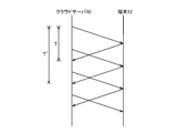
- FIG. 2 is a diagram showing an example of transmission of image data and an acknowledgment.
- an arrow from the cloud server 10 to the terminal 12 represents the transmission of image data
- an arrow from the terminal 12 to the cloud server 10 represents the transmission of an acknowledgment (Ack).
- the time T1 is the time from the transmission of the image data shown in FIG. 2 to the reception of the acknowledgment (Ack) indicating that the image data has been successfully received. It may be a time that is dynamically determined based on (statistics of a certain transmission time T).
- FIG. 3 is a diagram schematically showing an example of statistical data showing the above-mentioned statistics of the transmission time T.
- the cloud server 10 may generate the statistical data shown in FIG. Then, the cloud server 10 may determine the time T1 based on the statistical data. For example, the transmission time T in which the ratio from the top when the transmission times T are arranged in order from the longest is a predetermined% (for example, 10%) may be determined as the time T1. In this case, the transmission time T of 90% of the transmitted image data is the time T1 or less.
- the reference destination is unnecessary by changing the method of encoding the second image according to the possibility that the transmission of the first image data at the timing of encoding the second image has failed. Whether or not to generate the image data of 2 is controlled. For example, if the success of transmitting the first image data is not confirmed by the timing of encoding the second image, the reference destination is unnecessary without waiting for the time-out of receiving the first image data by the terminal 12. A second image data is generated.
- the reception timeout means for example, as shown in FIG. 2, after the cloud server 10 transmits the image data, the cloud server 10 sends a signal corresponding to the reception of the next image data of the image data to the terminal 12. It corresponds to the elapse of the time T'from to the reception.
- the time from the transmission of the first image data to the encoding of the second image is shorter than the time T'.
- the image data referred to here may be an I frame or a P frame.
- the reference when the success of the transmission of the first image data is not confirmed by the timing of encoding the second image, the reference is performed without waiting for the timeout of the reception of the first image data. Second image data is generated that does not require a tip. In this way, according to the present embodiment, it is possible to reduce the number of times of unnecessary transmission of image data due to failure in receiving the referenced image data. Further, by reducing the number of occurrences of such useless image data transmission, the time lag due to the interruption of image data transmission can be reduced, and the image display on the terminal 12 can be restarted as soon as possible. It becomes.
- FIG. 4 is a functional block diagram showing an example of the functions implemented in the cloud gaming system 1 according to the present embodiment. It should be noted that the cloud gaming system 1 according to the present embodiment does not need to implement all the functions shown in FIG. 4, and functions other than the functions shown in FIG. 4 (for example, execution of game processing based on an operation signal or the like). And the function of generating play images, etc.) may be implemented.
- the cloud server 10 includes, for example, a transmission failure expected data storage unit 20, an acquisition unit 22, a determination unit 24, an encoding processing unit 26, and a data transmission unit 28.
- the signal receiving unit 30 and the transmission failure expected data management unit 32 are included.
- the transmission failure expected data storage unit 20 is mainly implemented with the storage unit 10b.
- the acquisition unit 22 and the encoding processing unit 26 mainly implement the encoding / decoding unit 10d.
- the determination unit 24 and the transmission failure expected data management unit 32 are mainly implemented with the processor 10a.
- the data transmission unit 28 and the signal reception unit 30 are mainly mounted with the communication unit 10c.
- the above functions are implemented by executing the program including the instructions corresponding to the above functions installed in the cloud server 10 which is a computer on the processor 10a.
- This program is supplied to the cloud server 10 via a computer-readable information storage medium such as an optical disk, a magnetic disk, a magnetic tape, a magneto-optical disk, or a flash memory, or via the Internet or the like.
- the terminal 12 functionally includes, for example, a data receiving unit 40, a decoding processing unit 42, a display control unit 44, and a signal transmitting unit 46.
- the data receiving unit 40 is mainly mounted with the communication unit 12c.
- the decoding processing unit 42 mainly implements the encoding / decoding unit 12d.
- the display control unit 44 mainly mounts the processor 12a and the display unit 12f.
- the signal transmission unit 46 is mainly mounted with the communication unit 12c.
- the above functions are implemented by executing the program including the instructions corresponding to the above functions installed in the terminal 12 which is a computer on the processor 12a.
- This program is supplied to the terminal 12 via a computer-readable information storage medium such as an optical disk, a magnetic disk, a magnetic tape, a magneto-optical disk, or a flash memory, or via the Internet or the like.
- the transmission failure expected data storage unit 20 stores, for example, transmission failure expected data including identification information (for example, a frame number) of image data that is likely to have failed to be transmitted from the cloud server 10 to the terminal 12.
- identification information for example, a frame number
- the transmission failure expected data storage unit 20 may store, for example, the above-mentioned statistical data.
- the acquisition unit 22 sequentially acquires, for example, an image drawn in the frame buffer (play image in the above example).
- the acquisition unit 22 acquires, for example, the above-mentioned first image drawn in the frame buffer and acquires the second image drawn in the frame buffer.
- the second image is an image drawn in the frame buffer for the first time after the timing when a given time T1 has elapsed since the first image data was transmitted.
- the determination unit 24 determines, for example, whether or not it is necessary to generate image data that does not require a reference destination when encoding the image acquired by the acquisition unit 22.
- it is determined whether or not it is necessary to generate image data for which a reference destination is unnecessary, based on the transmission failure expected data stored in the transmission failure expected data storage unit 20.
- the encoding processing unit 26 generates image data by encoding the image acquired by the acquisition unit 22 according to the determination by the determination unit 24, for example.
- the encoding processing unit 26 generates, for example, first image data in which the above-mentioned first image is encoded. Further, the encoding processing unit 26 generates the second image data in which the above-mentioned second image is encoded. Further, the encoding processing unit 26 encodes an image different from the above-mentioned first image and the above-mentioned second image, so that the image is different from the above-mentioned first image data and the above-mentioned second image data. It also generates data.
- image data that does not require a reference destination such as an I frame
- image data that requires a reference destination may be generated.
- the data transmission unit 28 transmits, for example, the image data generated by the encoding processing unit 26 to the terminal 12.
- the data transmission unit 28 transmits, for example, the above-mentioned first image data.
- the data transmission unit 28 transmits the above-mentioned second image data.
- the data transmission unit 28 also transmits image data different from the above-mentioned first image data and the above-mentioned second image data.
- the signal receiving unit 30 receives, for example, a signal such as an acknowledgment (Ack) indicating that the image data has been successfully received from the terminal 12.
- a signal such as an acknowledgment (Ack) indicating that the image data has been successfully received from the terminal 12.
- Ack acknowledgment
- the transmission failure expected data management unit 32 manages, for example, whether or not the transmission of image data is expected to have failed.
- the transmission failure expected data management unit 32 may play a role of, for example, a confirmation unit for confirming the possibility that the transmission of the image data has failed.
- the transmission failure expected data management unit 32 may, for example, confirm whether or not the transmission of the image data is successful.
- the transmission failure expected data management unit 32 obtains the identification information (for example, the frame number) of the image data. Generate new transmission failure expected data including. Then, the transmission failure expected data management unit 32 stores the generated transmission failure expected data in the transmission failure expected data storage unit 20.
- the transmission failure expected data management unit 32 deletes the transmission failure expected data when the success of the transmission of the image data is confirmed.
- the transmission failure expected data management unit 32 transmits the image data to the statistical data stored in the transmission failure expected data storage unit 20 in response to the reception of the acknowledgment (Ack) associated with the image data. Add an element indicating the time T. Then, the transmission failure expected data management unit 32 determines the above-mentioned time T1 and timeout time T2 based on the statistical data to which the element is added.
- the timeout time T2 may be determined to be twice the longest transmission time T in the statistical data.
- the data receiving unit 40 receives, for example, image data transmitted from the cloud server 10.
- the decoding processing unit 42 generates an image by decoding the image data received by the data receiving unit 40, for example.
- the display control unit 44 displays, for example, the image generated by the decoding processing unit 42 on the display unit 12f of the terminal 12.
- the signal transmission unit 46 transmits a signal such as an affirmative response indicating that the image data has been successfully received to the cloud server 10.
- the acquisition unit 22 acquires the frame image of the frame drawn in the frame buffer (S101).
- the determination unit 24 confirms whether or not the new transmission failure expected data is stored in the transmission failure expected data storage unit 20 (S102).
- the determination unit 24 may generate image data that does not require a reference destination. It is determined that it is necessary (S103).
- the determination unit 24 deletes the new transmission failure expected data confirmed in the process shown in S102 (S104).
- the encoding processing unit 26 encodes the frame image acquired in the process shown in S101 to generate image data (S105). Similarly, when it is confirmed that the new transmission failure expected data is not stored in the process shown in S102 (S102: N), the encoding processing unit 26 encodes the frame image acquired in the process shown in S101. Then, image data is generated (S105).
- image data that does not require a reference destination such as an I frame
- image data that requires a reference destination such as a P frame
- image data that does not require a reference destination such as an I frame, or a P frame, etc. Any of the image data that requires a reference destination is generated.
- the data transmission unit 28 transmits the image data generated in the process shown in S105 to the terminal 12 (S106), and returns to the process shown in S101.
- FIGS. 6A and 6B An example of the flow of processing executed in response to the transmission of image data, which is executed in the cloud server 10 according to the present embodiment, will be described with reference to the flow charts shown in FIGS. 6A and 6B.
- a process executed in response to the transmission of the image data D1 will be shown, but the processes shown in FIGS. 6A and 6B are newly started each time the image data is transmitted, and a plurality of processes are started. Processing is executed in parallel.
- an acknowledgment (Ack) associated with the image data D1 (for example, an acknowledgment including identification information such as a frame number of the image data D1 (for example) Ac))) will be transmitted to the cloud server 10.
- the transmission failure expected data management unit 32 waits until the time T1 elapses from the transmission of the image data D1 (S201).
- the transmission failure expected data management unit 32 determines whether or not the signal receiving unit 30 has already received the acknowledgment (Ack) associated with the image data D1 from the terminal 12. Confirm (S202).
- the transmission failure expected data management unit 32 displays an element indicating the transmission time T (D1) of the image data D1 in the transmission failure expected data storage unit. It is added to the statistical data stored in 20 (S203).
- the transmission failure expected data management unit 32 updates (recalculates) the time T1 and the time T2 specified based on the statistical data to which the element indicating the transmission time T (D1) is added (S204). , The process shown in this process example is terminated.
- the transmission failure expected data management unit 32 when it is confirmed that the data has not been received (S202: N), the transmission failure expected data management unit 32 generates new transmission failure expected data including the identification information (for example, the frame number) of the image data D1. .. Then, the transmission failure expected data management unit 32 stores the generated transmission failure expected data in the transmission failure expected data storage unit 20 (S205). This case corresponds to the case where it is speculatively confirmed that the transmission of the image data D1 is likely to have failed.
- the transmission failure expected data management unit 32 confirms whether or not the signal receiving unit 30 has received the acknowledgment (Ack) associated with the image data D1 from the terminal 12 (S206).
- the transmission failure expected data management unit 32 deletes the transmission failure expected data stored in the transmission failure expected data storage unit 20 by the process shown in S203. (S207).
- the transmission failure expected data management unit 32 adds an element indicating the transmission time T (D1) of the image data D1 to the statistical data stored in the transmission failure expected data storage unit 20 (S208).
- the transmission failure expected data management unit 32 updates (recalculates) the time T1 and the time T2 specified based on the statistical data to which the element indicating the transmission time T (D1) is added (S209). , The process shown in this process example is terminated.
- the transmission failure expected data management unit 32 receives an acknowledgment (Ack) associated with the image data D2 in which the signal receiving unit 30 follows the image data D1.
- Ack acknowledgment associated with the image data D2 in which the signal receiving unit 30 follows the image data D1.
- the image data D2 may be image data transmitted in the frame immediately after the image data D1, or may be image data transmitted several frames after the image data D1.
- the transmission failure expected data management unit 32 sends an element indicating the transmission time T (D2) of the image data D2 to the transmission failure expected data storage unit 20. It is added to the stored statistical data (S211).
- the transmission failure expected data management unit 32 updates (recalculates) the time T1 and the time T2 specified based on the statistical data to which the element indicating the transmission time T (D2) is added (S212). , The process shown in this process example is terminated.
- the transmission failure expected data management unit 32 confirms whether or not the time T2 has elapsed from the transmission of the image data D1 (S213).
- the timeout time T2 is longer than the time T1. Further, here, the time T2 is different from the time T'shown in FIG.
- the image data D1 is the above-mentioned first image data
- the processes shown in S101 to S106 shown in FIG. 5 are executed. To do.
- the transmission failure expected data management unit 32 confirms whether or not the transmission failure expected data including the identification information of the image data D1 is stored in the process shown in S102.
- the transmission failure expected data management unit 32 of the first image data is based on whether or not a positive response (Ack) indicating that the first image data has been successfully received is received from the terminal 12. Check if the transmission was successful.
- the transmission failure expected data management unit 32 is given after transmitting the first image data even if the time T'required for determining that the failure to transmit the first image data has timed out has not elapsed. When the time T1 elapses, it is determined that the transmission of the first image data is likely to have failed.
- the terminal 12 succeeds in receiving the image data D1 thereafter. If so, the data expected to fail in transmission is deleted. In this case, it is confirmed that the transmission of the image data D1 is successful at the timing when the second image is encoded.
- the encoding processing unit 26 does not need a reference destination for the second image data, depending on whether or not the transmission of the first image data is confirmed by the timing when the second image is encoded. Will be controlled whether or not to generate.
- the cloud server 10 executes the determination process related to the generation and deletion of the transmission failure expected data, but the terminal 12 may execute the determination process related to the generation and deletion of the transmission failure expected data.
- the signal transmission unit 46 of the terminal 12 does not transmit an acknowledgment (Ack) to the cloud server 10. Instead, the signal transmission unit 46 of the terminal 12 sends a transmission failure expected signal corresponding to a transmission failure expected data generation instruction and a transmission failure expected cancellation signal corresponding to a transmission failure expected data deletion instruction to the cloud server 10. Send.
- the terminal 12 may further include a statistical data storage unit 50 in which the storage unit 12b is mainly mounted functionally.
- the time T3 may be the same as the time T1 described above, or may be different from the time T1. Further, the time T3 may be a time corresponding to the time T1. For example, the time T3 may be the time obtained by subtracting a predetermined time from the time T1.
- the time T3 is the reception time T'' which is the time from the reception of the image data shown in FIG. 8 to the reception of the next image data of the image data.
- the time may be dynamically determined based on (statistics of).
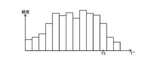
- FIG. 9 is a diagram schematically showing an example of statistical data showing the above-mentioned statistics of the reception time T ′′.
- the data receiving unit 40 may generate the statistical data shown in FIG. Then, the data receiving unit 40 may store the statistical data in the statistical data storage unit 50. Then, the data receiving unit 40 may determine the time T3 based on the statistical data. For example, when the reception time T ′′ is arranged in order from the longest one, the reception time T ′′ with a predetermined percentage (for example, 10%) from the top may be determined as the time T3. In this case, the reception time T ′′ of 90% of the received image data is the time T3 or less.
- timeout time T4 may be determined to be twice the longest reception time T ′′ in the statistical data.
- FIGS. 10A and 10B As an example of the flow of processing executed in response to the reception of image data executed in the terminal 12 according to the present embodiment.
- a process executed in response to the reception of the image data D3 will be shown, but the processes shown in FIGS. 10A and 10B are newly started each time the image data is received, and a plurality of processes are started. Processing is executed in parallel.
- the signal transmission unit 46 waits until the time T3 elapses from the reception of the image data D3 (S301).
- the signal transmitting unit 46 confirms whether or not the data receiving unit 40 has received the image data D4 which is the next image data of the image data D3 (S302).
- the process shown in S301 is skipped and the process shown in S302 is immediately executed.
- the data receiving unit 40 stores an element indicating the reception time T''(D4) of the image data D4 in the statistical data storage unit 50. It is added to the existing statistical data (S303).
- the data receiving unit 40 updates (recalculates) the time T3 and the time T4 specified based on the statistical data to which the element indicating the reception time T''(D4) is added (S304). The process shown in this processing example is terminated.
- the signal transmission unit 46 transmits a transmission failure expected signal indicating that the reception of the image data D4 has not been confirmed to the cloud server 10 (S302: N). S305).
- a transmission failure expected signal associated with the identification information (for example, a frame number) of the image data D4 is transmitted. This case corresponds to the case where it is speculatively confirmed that the transmission of the image data D4 is likely to have failed.
- the signal transmission unit 46 confirms whether or not the data reception unit 40 has received the image data D4 (S306).
- the signal transmission unit 46 transmits a transmission failure expectation cancellation signal indicating that the successful reception of the image data D4 has been confirmed to the cloud server 10. (S307).
- a transmission failure expectation cancellation signal associated with the identification information (for example, a frame number) of the image data D4 is transmitted.
- the data receiving unit 40 adds an element indicating the reception time T ′′ (D4) of the image data D4 to the statistical data stored in the statistical data storage unit 50 (S308).
- the data receiving unit 40 updates (recalculates) the time T3 and the time T4 specified based on the statistical data to which the element indicating the reception time T''(D4) is added (S309). The process shown in this processing example is terminated.
- the signal transmitting unit 46 confirms whether or not the data receiving unit 40 has received the image data D5 that further follows the image data D4 (S307: N). S310).
- the image data D5 may be image data received in the frame immediately after the image data D4, or may be image data received several frames after the image data D4.
- an element indicating the reception time T''(D5) of the image data D5 is added to the statistical data stored in the statistical data storage unit 50. (S311).
- half the time from the reception of the image data D3 to the reception of the image data D5 may be set as the reception time T ′′ (D5) of the image data D5.
- the data receiving unit 40 updates (recalculates) the time T3 and the time T4 specified based on the statistical data to which the element indicating the reception time T'' (D5) is added (S312).
- the process shown in this processing example is terminated.
- the processes shown in S311 and S312 may not be executed.
- the transmission failure expected data management unit 32 confirms whether or not the time T4 has elapsed from the reception of the image data D3 (S313).
- the timeout time T4 is longer than the time T3. Further, here, the time T4 is different from the time T'shown in FIG.
- the transmission failure expected data management unit 32 In response to the reception of the transmission failure expected signal associated with the image data identification information by the signal receiving unit 30, the transmission failure expected data management unit 32 generates new transmission failure expected data including the identification information. Then, the transmission failure expected data management unit 32 stores the generated transmission failure expected data in the transmission failure expected data storage unit 20.
- the transmission failure expected data management unit 32 is stored in the transmission failure expected data storage unit 20. Delete the transmission failure expected data including the identification information.
- the image data D4 is the above-mentioned first image data
- the processes shown in S101 to S106 shown in FIG. 5 are executed. To do.
- the transmission failure expected data management unit 32 confirms whether or not the transmission of the first image data is expected to have failed based on the transmission failure expected signal and the transmission failure expected cancellation signal described above.
- the encoding processing unit 26 does not need a reference destination depending on whether or not the transmission of the first image data is successful by the timing when the second image is encoded. Controls whether or not to generate the image data of 2. Therefore, in this case as well, it is possible to reduce the number of times of unnecessary transmission of image data due to the failure of receiving the referenced image data.
- the encoding / decoding unit 10d has two systems, and it is assumed that a pair of image data can be generated in parallel based on one image.
- the encoding processing unit 26 encodes the frame image acquired in the process shown in S401 to generate image data (S405). Similarly, when it is confirmed that the new transmission failure expected data is not stored in the process shown in S402, the (S402: N) encoding processing unit 26 encodes the frame image acquired in the process shown in S401. Then, image data is generated (S405).
- image data that does not require a reference destination such as an I frame is always generated. Will be done.
- image data that does not require a reference destination such as an I frame may be generated, and image data that requires a reference destination such as a P frame may not be generated.
- both image data that does not require a reference destination and image data that requires a reference destination may be generated.
- image data that does not require a reference destination such as an I frame, or a P frame, etc. Any of the image data that requires a reference destination is generated.
- the data transmission unit 28 confirms whether or not the image data that requires the reference destination, such as the P frame, has been generated by the process shown in S405 (S406).
- the data transmission unit 28 When it is confirmed that the image data that requires the reference destination has not been generated (S406: N), the data transmission unit 28 does not need a reference destination such as an I frame generated by the process shown in S405. A certain image data is transmitted to the terminal 12 (S407), and the process returns to the process shown in S401.
- the data transmission unit 28 still fails to transmit the new transmission failure expected data confirmed by the process shown in S402. It is confirmed whether or not it is stored in the expected data storage unit 20 (S408).
- the transmission failure expected data is stored in the transmission failure expected data storage unit 20 (S408: Y).
- the data transmission unit 28 transmits image data such as an I frame generated in the process shown in S405, which does not require a reference destination, to the terminal 12 (S407), and returns to the process shown in S401.
- the data transmission unit 28 transmits image data that requires a reference destination, such as a P frame, generated in the process shown in S405 to the terminal 12 (S409), and returns to the process shown in S401.
- the encoding processing unit 26 requires a reference destination on one side and no reference destination on the other side. A pair of second image data is generated. Then, the data transmission unit 28 transmits the second image data that requires a reference destination, depending on whether or not the success of the transmission of the first image data is confirmed by the timing of transmitting the second image data. It controls whether to transmit or to transmit the second image data that does not require a reference destination.
- the reference destination is unnecessary without waiting for the timeout of the reception of the first image data.
- Image data is generated and transmitted. In this way, also in this case, it is possible to reduce the number of times of unnecessary transmission of image data due to failure in receiving the referenced image data (here, for example, the first image data).
- both image data that does not require a reference destination and image data that requires a reference destination may be generated.
- the reference destination is required based on the probability that the transmission of the latest first image data has failed. It becomes possible to send.
- the process shown in FIG. 11 can set the time T1 and the time T3 to a shorter time than the process shown in FIG. In this case, the amount of data to be transmitted is not unnecessarily increased, and the recovery time when a transfer failure actually occurs can be shortened.
- the communication sequence described above is an example of a communication sequence related to transmission of image data such as an I frame that does not require a reference destination, and the scope of application of the present invention is not limited to the communication sequence described above. ..
- the frame image is described as a unit of encoding and transmission, but the encoding and transmission need not be performed in units of frame images.
- the encoding and transmission need not be performed in units of frame images.
- this embodiment is applicable.
- the present embodiment may be implemented by using a machine learning model such as deep learning in confirming the possibility that the transmission of image data has failed and dynamically determining the times T1 and T3 described above.
- a machine learning model such as deep learning in confirming the possibility that the transmission of image data has failed and dynamically determining the times T1 and T3 described above.
- the encoding processing unit 26 needs a reference destination for the image drawn in the frame buffer between the time when the first image is drawn and the time when the second image is drawn.
- Image data may be generated.
- the encoding processing unit 26 does not need a reference destination as necessary. Some image data may be generated.
- the cloud server 10 may change the data rate according to the transmission frequency of the image data, which does not require a reference destination based on the possibility that the transmission of the image data has failed.
- the transmission failure expected data management unit 32 may specify the number of times of transmission of image data that does not require a reference destination based on the probability that the transmission of image data has failed per unit time in the latest predetermined time.
- the encoding processing unit 26 may change the data rate according to the number of transmissions.
- the encoding processing unit 26 may change the data rate by changing, for example, the frequency of frame skipping or the change of the encoding QP value.
- the size of the image data and the transmission frequency of the image data may be changed.
- the encoding processing unit 26 may reduce the data rate. Further, when the number of transmissions falls below the second threshold value, the encoding processing unit 26 may increase the data rate.
- a plurality of threshold values are set, and the data rate may be changed in multiple stages.
- the present invention is not limited to the above-described embodiment.
- the present invention can be applied to a game system including a server arranged in a home and a terminal connected to the server via a home network, a public network, a carrier network of a mobile phone, or the like. .. That is, the computer network 14 may be a home network, a public network, a carrier network of a mobile phone, or the like. Further, the server and the terminal may be connected by wire or wirelessly.
- the content of the game to which the present invention is applied is not particularly limited, and the present invention can be applied to, for example, a game system that executes a game using virtual reality (VR) or augmented reality (AR).
- VR virtual reality
- AR augmented reality
Landscapes
- Engineering & Computer Science (AREA)
- Multimedia (AREA)
- Signal Processing (AREA)
- Computing Systems (AREA)
- Theoretical Computer Science (AREA)
- Two-Way Televisions, Distribution Of Moving Picture Or The Like (AREA)
- Compression Or Coding Systems Of Tv Signals (AREA)
Abstract
参照先の画像データの受信の失敗に伴う無駄な画像データの送信の発生回数を低減できる送信装置、送信方法及びプログラムを提供する。送信失敗見込データ管理部(32)は、第1の画像データの送信が失敗した見込みを確認する。第2の画像は、第1の画像データを送信してから所与の時間が経過したタイミング以降で初めてフレームバッファに描画された画像である。エンコード処理部(26)は、第2の画像をエンコードするタイミングまでに第1の画像データの送信が失敗した見込みに応じて、参照先が不要である第2の画像データを生成するか否かを制御する。
Description
本発明は、送信装置、送信方法及びプログラムに関する。
近年注目されているクラウドゲーミングサービスの技術では、クラウドサーバにおいてゲームのプレイ状況を表す画像が生成される。そして、当該画像をエンコードした画像データがクラウドサーバから端末に送信され、端末において当該画像データをデコードした画像が表示される。この一連の処理が繰り返し実行されることで、ゲームのプレイ状況を表す動画像が端末に表示される。
また、参照先を設定することで画像をエンコードして生成される画像データのサイズを圧縮する技術が知られている。例えば、フレーム画像を、参照先が不要であるIフレームにエンコードするよりも、参照先が必要であるPフレームにエンコードする方が、当該フレーム画像をエンコードした画像データのサイズは小さくなる。
サーバやネットワークの過負荷や接続不安定性の影響によって、画像データが端末に届かない、あるいは、端末が受信した画像データの一部又は全部が破損している、などのように、端末が画像データの受信に失敗することがある。
ここで端末が、参照先が必要である画像データの受信にたとえ成功しても、その前に当該画像データの参照先である画像データの受信に失敗していると、受信に成功した画像データをデコードできないため、クラウドサーバによる当該画像データの送信は無駄となる。このような無駄な画像データの送信を防ぐために、参照先の画像データの受信がタイムアウトしたことに応じて、参照先が不要である画像データを送信することが考えられる。
しかし、この場合であっても、参照先の画像データの受信がタイムアウトするまでの間に行われる画像データの送信は無駄となる。このような無駄な画像データの送信の発生回数が低減されると、画像データの送信が中断されることによるタイムラグが削減され、端末における画像の表示の再開をいち早く行うことが可能となる。
本発明は上記実情に鑑みてなされたものであって、その目的の一つは、参照先の画像データの受信の失敗に伴う無駄な画像データの送信の発生回数を低減できる送信装置、送信方法及びプログラムを提供することにある。
上記課題を解決するために、本発明に係る送信装置は、フレームバッファに描画された第1の画像を取得し、前記フレームバッファに描画された第2の画像を取得する取得部と、前記第1の画像をエンコードした第1の画像データを生成し、前記第2の画像をエンコードした第2の画像データを生成するエンコード処理部と、前記第1の画像データを送信し、前記第2の画像データを送信する送信部と、前記第1の画像データの送信が失敗した見込みを確認する確認部と、を含み、前記第2の画像は、前記第1の画像データを送信してから所与の時間が経過したタイミング以降で初めて前記フレームバッファに描画された画像であり、前記エンコード処理部は、前記第2の画像をエンコードするタイミングにおける前記第1の画像データの送信が失敗した見込みに応じて、参照先が不要である前記第2の画像データを生成するか否かを制御する。
本発明の一態様では、前記確認部は、前記第1の画像データの送信が成功したか否かを確認し、前記エンコード処理部は、前記第2の画像をエンコードするタイミングまでに前記第1の画像データの送信の成功が確認されたか否かに応じて、参照先が不要である前記第2の画像データを生成するか否かを制御する。
この態様では、前記確認部は、前記第1の画像データの受信に成功したことを示す肯定応答を前記第1の画像データを受信する端末から受信したか否かに基づいて、前記第1の画像データの送信が成功したか否かを確認してもよい。
あるいは、前記確認部は、前記第1の画像データを受信する端末から送信される、前記第1の画像データの受信が確認されていないことを示す送信失敗見込信号、及び、当該送信失敗見込信号の送信後に前記端末から送信される、前記第1の画像データの受信の成功が確認されたことを示す送信失敗見込解除信号に基づいて、前記第1の画像データの送信が成功したか否かを確認してもよい。
また、前記エンコード処理部は、前記第2の画像をエンコードするタイミングまでに前記第1の画像データの送信の成功が確認されていない場合に、一方は参照先が必要であり他方は参照先が不要である一対の前記第2の画像データを生成し、前記送信部は、前記第2の画像データを送信するタイミングまでに前記第1の画像データの送信の成功が確認されたか否かに応じて、参照先が必要である前記第2の画像データを送信するか、参照先が不要である前記第2の画像データを送信するかを制御してもよい。
また、本発明の一態様では、前記確認部は、前記第1の画像データの送信の失敗がタイムアウトしたことの判定に必要な時間が経過していなくても、前記第1の画像データを送信してから前記所与の時間が経過した際には、前記第1の画像データの送信が失敗した見込みであると判定する。
また、本発明の一態様では、前記所与の時間は、画像データの送信実績の統計に基づいて動的に決定される時間である。
また、本発明の一態様では、前記エンコード処理部は、前記見込みに基づく参照先が不要である画像データの送信頻度に応じて、データレートを変化させる。
また、本発明に係る送信方法は、フレームバッファに描画された第1の画像を取得する第1取得ステップと、前記第1の画像をエンコードした第1の画像データを生成する第1エンコード処理ステップと、前記第1の画像データを送信する第1送信ステップと、前記第1の画像データを送信してから所与の時間が経過したタイミング以降で初めて前記フレームバッファに描画された第2の画像を取得する第2取得ステップと、前記第1の画像データの送信が失敗した見込みを確認する確認ステップと、前記第2の画像をエンコードした第2の画像データを生成する第2エンコード処理ステップと、前記第2の画像データを送信する第2送信ステップと、を含み、前記第2エンコード処理ステップでは、前記第2の画像をエンコードするタイミングにおける前記第1の画像データの送信が失敗した見込みに応じて、参照先が不要である前記第2の画像データを生成するか否かを制御する。
また、本発明に係るプログラムは、フレームバッファに描画された第1の画像を取得する第1取得手順、前記第1の画像をエンコードした第1の画像データを生成する第1エンコード処理手順、前記第1の画像データを送信する第1送信手順、前記第1の画像データを送信してから所与の時間が経過したタイミング以降で初めて前記フレームバッファに描画された第2の画像を取得する第2取得手順、前記第1の画像データの送信が失敗した見込みを確認する確認手順、前記第2の画像をエンコードした第2の画像データを生成する第2エンコード処理手順、前記第2の画像データを送信する第2送信手順、をコンピュータに実行させ、前記第2エンコード処理手順では、前記第2の画像をエンコードするタイミングにおける前記第1の画像データの送信が失敗した見込みに応じて、参照先が不要である前記第2の画像データを生成するか否かを制御する。
図1は、本発明の一実施形態に係るクラウドゲーミングシステム1の全体構成の一例を示す図である。図1に示すように、本実施形態に係るクラウドゲーミングシステム1には、いずれもコンピュータを中心に構成された、クラウドサーバ10と端末12とが含まれている。クラウドサーバ10と端末12とは、インターネットなどのコンピュータネットワーク14に接続されており、クラウドサーバ10と端末12とは互いに通信可能となっている。
本実施形態に係るクラウドサーバ10は、例えば、クラウドゲーミングサービスに係るゲームのプログラムを実行するサーバコンピュータである。クラウドサーバ10は、当該ゲームのプレイ状況を表す動画像を、当該ゲームをプレイしているユーザが利用している端末12に配信する。
図1に示すように、クラウドサーバ10には、例えば、プロセッサ10a、記憶部10b、通信部10c、エンコード・デコード部10dが含まれている。
プロセッサ10aは、例えばCPU等のプログラム制御デバイスであって、記憶部10bに記憶されたプログラムに従って各種の情報処理を実行する。本実施形態に係るプロセッサ10aには、当該CPUから供給されるグラフィックスコマンドやデータに基づいてフレームバッファに画像を描画するGPU(Graphics Processing Unit)も含まれている。
記憶部10bは、例えばROMやRAM等の記憶素子やソリッドステートドライブ(SSD)などである。記憶部10bには、プロセッサ10aによって実行されるプログラムなどが記憶される。また、本実施形態に係る記憶部10bには、プロセッサ10aに含まれるGPUにより画像が描画されるフレームバッファの領域が確保されている。
通信部10cは、例えばコンピュータネットワーク14を介して、端末12などといったコンピュータとの間でデータを授受するための通信インタフェースである。
エンコード・デコード部10dは、例えばエンコーダとデコーダとを含む。当該エンコーダは、入力される画像をエンコードすることにより当該画像を表す画像データを生成する。また当該デコーダは、入力される画像データをデコードして、当該画像データが表す画像を出力する。
本実施形態に係る端末12は、例えばクラウドゲーミングサービスを利用するユーザが利用する、ゲームコンソール、パーソナルコンピュータ、タブレット端末、スマートフォンなどのコンピュータである。
図1に示すように、端末12には、例えば、プロセッサ12a、記憶部12b、通信部12c、エンコード・デコード部12d、操作部12e、表示部12f、が含まれている。
プロセッサ12aは、例えばCPU等のプログラム制御デバイスであって、記憶部12bに記憶されたプログラムに従って各種の情報処理を実行する。本実施形態に係るプロセッサ12aには、当該CPUから供給されるグラフィックスコマンドやデータに基づいてフレームバッファに画像を描画するGPU(Graphics Processing Unit)も含まれている。
記憶部12bは、例えばROMやRAM等の記憶素子やソリッドステートドライブ(SSD)などである。記憶部12bには、プロセッサ12aによって実行されるプログラムなどが記憶される。また、本実施形態に係る記憶部12bには、プロセッサ12aに含まれるGPUにより画像が描画されるフレームバッファの領域が確保されている。
通信部12cは、例えばコンピュータネットワーク14を介して、クラウドサーバ10などといったコンピュータとの間でデータを授受するための通信インタフェースである。
エンコード・デコード部12dは、例えばエンコーダとデコーダとを含む。当該エンコーダは、入力される画像をエンコードすることにより当該画像を表す画像データを生成する。また当該デコーダは、入力される画像データをデコードして、当該画像データが表す画像を出力する。
操作部12eは、例えばプロセッサ12aに対する操作入力を行うための操作部材である。
表示部12fは、例えば液晶ディスプレイや有機ELディスプレイなどの表示デバイスである。
なお、端末12に、GPUやフレームバッファが含まれている必要はない。
本実施形態に係る端末12に対するゲームに関する操作が操作部12eを介して行われると、当該操作を表す操作信号が端末12からクラウドサーバ10に送信される。そして、クラウドサーバ10において当該操作信号に応じたゲーム処理が実行される。そして操作信号の影響を受けた当該ゲームのプレイ状況を表すフレーム画像であるプレイ画像が生成され、当該プレイ画像がクラウドサーバ10のフレームバッファに描画される。本実施形態では、ゲーム処理及びプレイ画像の生成が繰り返し実行される。
そして、クラウドサーバ10は、フレームバッファに描画されたプレイ画像を順次取得して、当該プレイ画像を表す画像データを生成する。そして、クラウドサーバ10は、生成される画像データを端末12に送信する。そして端末12は、クラウドサーバ10から受信する画像データをデコードすることにより生成されるプレイ画像を表示部12fに表示させる。このようにして、本実施形態では一連のプレイ画像が表示部12fに表示される。
本実施形態では例えば、クラウドサーバ10は、Iフレームなどの、参照先が不要な画像データ、又は、Pフレームなどの、参照先が必要な画像データを端末12に送信する。なお、ここで参照先である画像データは、Iフレームであることもあり得るし、Pフレームであることもあり得る。
例えば、フレームバッファに描画された第1の画像をエンコードすることにより第1の画像データが生成され、フレームバッファに描画された第2の画像をエンコードすることにより第2の画像データが生成されることとする。ここで、第2の画像は、第1の画像データが送信されてから所与の時間T1が経過したタイミング以降で初めてフレームバッファに描画された画像であることとする。所与の時間T1は、送信が失敗した見込みであると投機的に判定するためのタイムアウト時間(投機的タイムアウト時間)である。第1の画像データの送信後であって、第2の画像データの送信前に、1又は複数の画像がフレームバッファに描画され、これらの画像が順次エンコードされることで生成される画像データが送信されてもよい。すなわち、第2の画像は、第1の画像の直後のフレームに描画される画像でなくてもよい。
本実施形態では、例えば、図2に示すように、端末12は、画像データの受信に成功すると、画像データの受信に成功したことを示す肯定応答(Ack)を、クラウドサーバ10に送信する。図2は、画像データ及び肯定応答の送信の一例を示す図である。図2では、クラウドサーバ10から端末12への矢印によって、画像データの送信が表現され、端末12からクラウドサーバ10への矢印によって、肯定応答(Ack)の送信が表現されている。
ここで、時間T1が、画像データの送信実績の統計(例えば、図2に示す、画像データの送信から、当該画像データの受信に成功したことを示す肯定応答(Ack)の受信までの時間である送信時間Tの統計)に基づいて、動的に決定される時間であってもよい。
図3は、上述の送信時間Tの統計を示す統計データの一例を模式的に示す図である。例えば、クラウドサーバ10が、図3に示す統計データを生成してもよい。そして、クラウドサーバ10が、統計データに基づいて、時間T1を決定してもよい。例えば、送信時間Tを長いものから順に並べた際における上位からの割合が所定%(例えば10%)である送信時間Tが、時間T1に決定されてもよい。この場合、送信された画像データの90%の送信時間Tは、時間T1以下であることとなる。
そして本実施形態では、第2の画像をエンコードするタイミングにおける第1の画像データの送信が失敗した見込みに応じて、第2の画像をエンコードする方法を変えることで、参照先が不要である第2の画像データを生成するか否かが制御される。例えば、第2の画像をエンコードするタイミングまでに第1の画像データの送信の成功が確認されていない場合は、端末12による第1の画像データの受信のタイムアウトを待たずに参照先が不要である第2の画像データが生成される。
ここで受信のタイムアウトとは、例えば、図2に示すように、クラウドサーバ10が画像データを送信してから、当該画像データの次の画像データの受信に応じた信号をクラウドサーバ10が端末12から受信するまでの時間T’が経過することが相当する。第1の画像データを送信してから、第2の画像をエンコードするまでの時間は、時間T’よりも短い。
端末12が、参照先が必要である画像データの受信にたとえ成功しても、その前に、当該画像データの参照先である画像データの受信に失敗していると、受信に成功した画像データをデコードできない。そのため、当該画像データの送信は無駄となる。なおここで参照先である画像データは、IフレームであることもあればPフレームであることもある。
ここで、無駄な画像データの送信を防ぐために、参照先の画像データの受信がタイムアウトしたことに応じて、参照先が不要である画像データを送信することが考えられる。
しかし、この場合であっても、参照先の画像データの受信がタイムアウトするまでの間に行われる画像データの送信は無駄となる。
本実施形態では上述のように、第2の画像をエンコードするタイミングまでに第1の画像データの送信の成功が確認されていない場合は、第1の画像データの受信のタイムアウトを待たずに参照先が不要である第2の画像データが生成される。このようにして、本実施形態によれば、参照先の画像データの受信の失敗に伴う無駄な画像データの送信の発生回数を低減できるようにした。また、このような無駄な画像データの送信の発生回数が低減されることで、画像データの送信が中断されることによるタイムラグが削減され、端末12における画像の表示の再開をいち早く行うことが可能となる。
図4は、本実施形態に係るクラウドゲーミングシステム1で実装される機能の一例を示す機能ブロック図である。なお、本実施形態に係るクラウドゲーミングシステム1で、図4に示す機能のすべてが実装される必要はなく、また、図4に示す機能以外の機能(例えば、操作信号等に基づくゲーム処理の実行やプレイ画像の生成の機能など)が実装されていても構わない。
図4に示すように、本実施形態に係るクラウドサーバ10には、機能的には例えば、送信失敗見込データ記憶部20、取得部22、決定部24、エンコード処理部26、データ送信部28、信号受信部30、送信失敗見込データ管理部32、が含まれる。
送信失敗見込データ記憶部20は、記憶部10bを主として実装される。取得部22、エンコード処理部26は、エンコード・デコード部10dを主として実装される。決定部24、送信失敗見込データ管理部32は、プロセッサ10aを主として実装される。データ送信部28、信号受信部30は、通信部10cを主として実装される。
そして以上の機能は、コンピュータであるクラウドサーバ10にインストールされた、以上の機能に対応する指令を含むプログラムをプロセッサ10aで実行することにより実装されている。このプログラムは、例えば、光ディスク、磁気ディスク、磁気テープ、光磁気ディスク、フラッシュメモリ等のコンピュータ読み取り可能な情報記憶媒体を介して、あるいは、インターネットなどを介してクラウドサーバ10に供給される。
また、図4に示すように、本実施形態に係る端末12には、機能的には例えば、データ受信部40、デコード処理部42、表示制御部44、信号送信部46、が含まれる。
データ受信部40は、通信部12cを主として実装される。デコード処理部42は、エンコード・デコード部12dを主として実装される。表示制御部44は、プロセッサ12a及び表示部12fを主として実装される。信号送信部46は、通信部12cを主として実装される。
そして以上の機能は、コンピュータである端末12にインストールされた、以上の機能に対応する指令を含むプログラムをプロセッサ12aで実行することにより実装されている。このプログラムは、例えば、光ディスク、磁気ディスク、磁気テープ、光磁気ディスク、フラッシュメモリ等のコンピュータ読み取り可能な情報記憶媒体を介して、あるいは、インターネットなどを介して端末12に供給される。
送信失敗見込データ記憶部20は、本実施形態では例えば、クラウドサーバ10から端末12への送信に失敗した見込みが高い画像データの識別情報(例えばフレーム番号)を含む送信失敗見込データを記憶する。
また、送信失敗見込データ記憶部20は、本実施形態では例えば、上述の統計データを記憶してもよい。
取得部22は、本実施形態では例えば、本実施形態では例えば、フレームバッファに描画された画像(上述の例ではプレイ画像)を順次取得する。取得部22は、例えば、フレームバッファに描画された上述の第1の画像を取得し、フレームバッファに描画された第2の画像を取得する。ここで、第2の画像は、上述のように、第1の画像データを送信してから所与の時間T1が経過したタイミング以降で初めてフレームバッファに描画された画像である。
決定部24は、本実施形態では例えば、取得部22が取得する画像のエンコードの際に、参照先が不要である画像データを生成する必要があるか否かを決定する。ここでは例えば、送信失敗見込データ記憶部20に記憶されている送信失敗見込データに基づいて、参照先が不要である画像データを生成する必要があるか否かが決定される。
エンコード処理部26は、本実施形態では例えば、決定部24による決定に従って取得部22が取得する画像をエンコードすることで、画像データを生成する。エンコード処理部26は、例えば、上述の第1の画像をエンコードした第1の画像データを生成する。また、エンコード処理部26は、上述の第2の画像をエンコードした第2の画像データを生成する。また、エンコード処理部26は、上述の第1の画像や上述の第2の画像とは異なる画像をエンコードすることで、上述の第1の画像データや上述の第2の画像データとは異なる画像データも生成する。ここで例えば、決定部24により参照先が不要である画像データを生成することが必要であると決定される場合は、Iフレームなどの、参照先が不要である画像データが生成される。この場合以外は、参照先が必要である画像データが生成されてもよい。
データ送信部28は、本実施形態では例えば、エンコード処理部26により生成される画像データを端末12に送信する。データ送信部28は、例えば、上述の第1の画像データを送信する。また、データ送信部28は、上述の第2の画像データを送信する。また、データ送信部28は、上述の第1の画像データや上述の第2の画像データとは異なる画像データも送信する。
信号受信部30は、本実施形態では例えば、画像データの受信に成功したことを示す肯定応答(Ack)などの信号を端末12から受信する。
送信失敗見込データ管理部32は、本実施形態では例えば、画像データの送信が失敗した見込みであるか否かを管理する。送信失敗見込データ管理部32は、例えば、当該画像データの送信が失敗した見込みを確認する確認部の役割を担ってもよい。送信失敗見込データ管理部32は、例えば、当該画像データの送信が成功したか否かを確認してもよい。そして、送信失敗見込データ管理部32は、画像データの送信が失敗した見込みである場合に(例えば、送信の成功が確認されていない場合に)、当該画像データの識別情報(例えばフレーム番号)を含む新たな送信失敗見込データを生成する。そして、送信失敗見込データ管理部32は、生成された送信失敗見込データを送信失敗見込データ記憶部20に記憶させる。
その後、送信失敗見込データ管理部32は、当該画像データの送信の成功が確認された場合に、当該送信失敗見込データを消去する。
また、送信失敗見込データ管理部32は、画像データに関連付けられた肯定応答(Ack)の受信に応じて、送信失敗見込データ記憶部20に記憶されている統計データに、当該画像データについての送信時間Tを示す要素を追加する。そして、送信失敗見込データ管理部32は、要素が追加された統計データに基づいて、上述の時間T1、及び、タイムアウト時間T2を決定する。ここで例えば、統計データにおいて最も長い送信時間Tの2倍の時間が、タイムアウト時間T2に決定されてもよい。
データ受信部40は、本実施形態では例えば、クラウドサーバ10から送信される画像データを受信する。
デコード処理部42は、本実施形態では例えば、データ受信部40が受信する画像データをデコードすることにより画像を生成する。
表示制御部44は、本実施形態では例えば、デコード処理部42により生成される画像を端末12の表示部12fに表示させる。
信号送信部46は、本実施形態では例えば、画像データの受信に成功した際に、当該画像データの受信に成功したことを示す肯定応答などの信号をクラウドサーバ10に送信する。
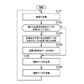
ここで、本実施形態に係るクラウドサーバ10において実行される、フレームバッファに画像が描画される度に実行される処理の流れの一例を、図5に例示するフロー図を参照しながら説明する。図5に示すS101~S106に示す処理は、固定あるいは可変のフレームレートで繰り返し実行される。なお、本処理例では、各ループにおいて新たなフレーム画像がフレームバッファに描画されることとする。
まず、取得部22が、フレームバッファに描画された当該フレームのフレーム画像を取得する(S101)。
そして、決定部24が、新たな送信失敗見込データが送信失敗見込データ記憶部20に記憶されているか否かを確認する(S102)。
新たな送信失敗見込データが送信失敗見込データ記憶部20に記憶されていることが確認された場合は(S102:Y)、決定部24は、参照先が不要である画像データを生成することが必要であると決定する(S103)。
そして、決定部24は、S102に示す処理で確認された新たな送信失敗見込データを消去する(S104)。
そして、S104に示す処理が終了すると、エンコード処理部26が、S101に示す処理で取得されたフレーム画像をエンコードすることで、画像データを生成する(S105)。S102に示す処理で新たな送信失敗見込データが記憶されていないことが確認された場合も同様に(S102:N)エンコード処理部26が、S101に示す処理で取得されたフレーム画像をエンコードすることで、画像データを生成する(S105)。
S105に示す処理では、S103に示す処理で参照先が不要である画像データを生成することが必要であると決定された場合は、Iフレームなどの、参照先が不要である画像データが必ず生成される。この場合は、Pフレームなどの、参照先が必要な画像データは生成されない。
一方、S103に示す処理で参照先が不要である画像データを生成することが必要であると決定されなかった場合は、Iフレームなどの、参照先が不要である画像データ、又は、Pフレームなどの、参照先が必要な画像データのいずれかが生成される。
そして、データ送信部28が、S105に示す処理で生成された画像データを端末12に送信して(S106)、S101に示す処理に戻る。
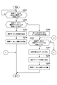
次に、本実施形態に係るクラウドサーバ10において実行される、画像データの送信に応じて実行される処理の流れの一例を、図6A及び図6Bに示すフロー図を参照しながら説明する。なお、以下では、一例として、画像データD1の送信に応じて実行される処理を示すが、図6A及び図6Bに示す処理は、画像データの送信が実行される都度、新たに開始され、複数の処理が並列的に実行される。
本処理例では、端末12は、画像データD1の受信に成功した際に、画像データD1に関連付けられた肯定応答(Ack)(例えば、画像データD1のフレーム番号等の識別情報を含む肯定応答(Ack))をクラウドサーバ10に送信することとする。
まず、送信失敗見込データ管理部32が、画像データD1の送信から時間T1が経過するまで待機する(S201)。
画像データD1の送信から時間T1が経過すると、送信失敗見込データ管理部32が、信号受信部30が既に画像データD1に関連付けられた肯定応答(Ack)を端末12から受信しているか否かを確認する(S202)。
ここで、受信していることが確認された場合は(S202:Y)、送信失敗見込データ管理部32が、画像データD1の送信時間T(D1)を示す要素を、送信失敗見込データ記憶部20に記憶されている統計データに追加する(S203)。
そして、送信失敗見込データ管理部32が、送信時間T(D1)を示す要素が追加された統計データに基づいて特定される時間T1、及び、時間T2を更新(再計算)して(S204)、本処理例に示す処理は終了される。
一方、受信していないことが確認された場合は(S202:N)、送信失敗見込データ管理部32は、画像データD1の識別情報(例えばフレーム番号)を含む新たな送信失敗見込データを生成する。そして、送信失敗見込データ管理部32は、生成された送信失敗見込データを送信失敗見込データ記憶部20に記憶させる(S205)。この場合は、投機的に、画像データD1の送信が失敗した見込みであることが確認される場合に相当する。
そして、送信失敗見込データ管理部32が、信号受信部30が画像データD1に関連付けられた肯定応答(Ack)を端末12から受信したか否かを確認する(S206)。
ここで、受信したことが確認された場合は(S206:Y)、送信失敗見込データ管理部32が、S203に示す処理で送信失敗見込データ記憶部20に記憶された送信失敗見込データを消去する(S207)。
そして、送信失敗見込データ管理部32が、画像データD1の送信時間T(D1)を示す要素を、送信失敗見込データ記憶部20に記憶されている統計データに追加する(S208)。
そして、送信失敗見込データ管理部32が、送信時間T(D1)を示す要素が追加された統計データに基づいて特定される時間T1、及び、時間T2を更新(再計算)して(S209)、本処理例に示す処理は終了される。
一方、受信していないことが確認された場合は(S206:N)、送信失敗見込データ管理部32は、信号受信部30が画像データD1に後続する画像データD2に関連付けられた肯定応答(Ack)端末12から受信したか否かを確認する(S210)。画像データD2は、画像データD1の直後のフレームに送信される画像データであってもよいし、画像データD1の数フレーム後に送信される画像データであってもよい。
ここで、受信したことが確認された場合は(S210:Y)、送信失敗見込データ管理部32が、画像データD2の送信時間T(D2)を示す要素を、送信失敗見込データ記憶部20に記憶されている統計データに追加する(S211)。
そして、送信失敗見込データ管理部32が、送信時間T(D2)を示す要素が追加された統計データに基づいて特定される時間T1、及び、時間T2を更新(再計算)して(S212)、本処理例に示す処理は終了される。
一方、受信していないことが確認された場合は(S210:N)、送信失敗見込データ管理部32は、画像データD1の送信から時間T2が経過したか否かを確認する(S213)。ここで、上述のように、タイムアウトの時間T2は、時間T1より長い。また、ここでは、時間T2は、図2に示す時間T’とは異なる。
画像データD1の送信から時間T2が経過したことが確認された場合、すなわち、タイムアウトが発生した場合は(S213:Y)、本処理例に示す処理は終了される。
一方、画像データD1の送信から時間T2が経過していないことが確認された場合は(S213:N)、S206に示す処理に戻る。
ここで例えば、画像データD1が上述の第1の画像データであり、上述の第2の画像がフレームバッファに描画された際に図5に示すS101~S106に示す処理が実行されることを想定する。
この場合、送信失敗見込データ管理部32は、S102に示す処理で、画像データD1の識別情報を含む送信失敗見込データが記憶されているか否かを確認する。ここでは例えば、送信失敗見込データ管理部32は、第1の画像データの受信に成功したことを示す肯定応答(Ack)を端末12から受信したか否かに基づいて、第1の画像データの送信が成功したか否かを確認する。送信失敗見込データ管理部32は、第1の画像データの送信の失敗がタイムアウトしたことの判定に必要な時間T’が経過していなくても、第1の画像データを送信してから所与の時間T1が経過した際には、第1の画像データの送信が失敗した見込みであると判定する。
画像データD1の送信から時間T1が経過して画像データD1に関連付けられた送信失敗見込データが送信失敗見込データ記憶部20に記憶されても、その後、端末12が画像データD1の受信に成功すれば、当該送信失敗見込データは消去される。この場合は、第2の画像がエンコードされるタイミングにおいて、画像データD1の送信が成功したと確認される。
このようにして、エンコード処理部26は、第2の画像がエンコードされるタイミングまでに第1の画像データの送信が確認されたか否かに応じて、参照先が不要である第2の画像データを生成するか否かを制御することとなる。
以上の説明では、クラウドサーバ10が送信失敗見込データの生成や消去に係る判断処理を実行しているが、端末12が送信失敗見込データの生成や消去に係る判断処理を実行してもよい。
この場合は、端末12の信号送信部46は、肯定応答(Ack)をクラウドサーバ10に送信しない。その代わりに、端末12の信号送信部46は、送信失敗見込データの生成指示に相当する送信失敗見込信号、及び、送信失敗見込データの消去指示に相当する送信失敗見込解除信号をクラウドサーバ10に送信する。
また、この場合、上述の時間T1、及び、時間T2の代わりに、時間T3、及び、時間T4が用いられる。また、この場合、図7に示すように、端末12が、機能的に、記憶部12bを主として実装される統計データ記憶部50をさらに含んでいてもよい。
ここで時間T3は、上述の時間T1と同じであってもよいし、時間T1とは異なっていてもよい。また、時間T3が時間T1に応じた時間であってもよい。例えば、時間T3が、時間T1に所定の時間を引いた時間であってもよい。
また、時間T3が、画像データの送信実績の統計(例えば、図8に示す、画像データを受信してから、当該画像データの次の画像データを受信するまでの時間である受信時間T’’の統計)に基づいて、動的に決定される時間であってもよい。
図9は、上述の受信時間T’’の統計を示す統計データの一例を模式的に示す図である。ここで例えば、データ受信部40が、図9に示す統計データを生成してもよい。そして、データ受信部40が、統計データ記憶部50に統計データを記憶させてもよい。そして、データ受信部40が、統計データに基づいて、時間T3を決定してもよい。例えば、受信時間T’’を長いものから順に並べた際における上位からの割合が所定%(例えば10%)ある受信時間T’’が、時間T3に決定されてもよい。この場合、受信された画像データの90%の受信時間T’’は、時間T3以下であることとなる。
また、統計データにおいて最も長い受信時間T’’の2倍の時間が、タイムアウト時間T4に決定されてもよい。
この場合について、本実施形態に係る端末12において実行される、画像データの受信に応じて実行される処理の流れの一例を、図10A及び図10Bに示すフロー図を参照しながら説明する。なお、以下では、一例として、画像データD3の受信に応じて実行される処理を示すが、図10A及び図10Bに示す処理は、画像データの受信が実行される都度、新たに開始され、複数の処理が並列的に実行される。
まず、信号送信部46が、画像データD3の受信から時間T3が経過するまで待機する(S301)。
画像データD3の受信から時間T3が経過すると、信号送信部46が、データ受信部40が画像データD3の次の画像データである画像データD4を受信したか否かを確認する(S302)。なお本処理例に示す処理の初回実行時には、S301に示す処理はスキップされ、直ちにS302に示す処理が実行される。
ここで、受信したことが確認された場合は(S302:Y)、データ受信部40が、画像データD4の受信時間T’’(D4)を示す要素を、統計データ記憶部50に記憶されている統計データに追加する(S303)。
そして、データ受信部40が、受信時間T’’(D4)を示す要素が追加された統計データに基づいて特定される時間T3、及び、時間T4を更新(再計算)して(S304)、本処理例に示す処理は終了される。
一方、受信していないことが確認された場合は(S302:N)、信号送信部46は、画像データD4の受信が確認されていないことを示す送信失敗見込信号をクラウドサーバ10に送信する(S305)。ここでは例えば、画像データD4の識別情報(例えばフレーム番号)に関連付けられた送信失敗見込信号が送信される。この場合は、投機的に、画像データD4の送信が失敗した見込みであることが確認される場合に相当する。
そして、信号送信部46は、データ受信部40が画像データD4を受信したか否かを確認する(S306)。
ここで、受信したことが確認された場合は(S306:Y)、信号送信部46は、画像データD4の受信の成功が確認されたことを示す送信失敗見込解除信号をクラウドサーバ10に送信する(S307)。ここでは例えば、画像データD4の識別情報(例えばフレーム番号)に関連付けられた送信失敗見込解除信号が送信される。
そして、データ受信部40が、画像データD4の受信時間T’’(D4)を示す要素を、統計データ記憶部50に記憶されている統計データに追加する(S308)。
そして、データ受信部40が、受信時間T’’(D4)を示す要素が追加された統計データに基づいて特定される時間T3、及び、時間T4を更新(再計算)して(S309)、本処理例に示す処理は終了される。
一方、受信していないことが確認された場合は(S307:N)、信号送信部46は、データ受信部40が画像データD4にさらに後続する画像データD5を受信したか否かを確認する(S310)。画像データD5は、画像データD4の直後のフレームに受信される画像データであってもよいし、画像データD4の数フレーム後に受信される画像データであってもよい。
ここで、受信したことが確認された場合は(S310:Y)、画像データD5の受信時間T’’(D5)を示す要素を、統計データ記憶部50に記憶されている統計データに追加する(S311)。ここでは例えば、画像データD3の受信から画像データD5の受信までの時間の半分の時間が、画像データD5の受信時間T’’(D5)とされてもよい。
そして、データ受信部40が、受信時間T’’(D5)を示す要素が追加された統計データに基づいて特定される時間T3、及び、時間T4を更新(再計算)して(S312)、本処理例に示す処理は終了される。なお、S311、及び、S312に示す処理は実行されなくてもよい。
一方、受信していないことが確認された場合は(S310:N)、送信失敗見込データ管理部32は、画像データD3の受信から時間T4が経過したか否かを確認する(S313)。ここで、上述のように、タイムアウトの時間T4は、時間T3より長い。また、ここでは、時間T4は、図2に示す時間T’とは異なる。
画像データD3の受信から時間T4が経過したことが確認された場合は(S313:Y)、本処理例に示す処理は終了される。
一方、画像データD3の受信から時間T4が経過していないことが確認された場合、すなわち、タイムアウトが発生した場合は(S313:N)、S306に示す処理に戻る。
信号受信部30による画像データの識別情報に関連付けられた送信失敗見込信号の受信に応じて、送信失敗見込データ管理部32は、当該識別情報を含む新たな送信失敗見込データを生成する。そして、送信失敗見込データ管理部32は、生成された送信失敗見込データを送信失敗見込データ記憶部20に記憶させる。
また、信号受信部30による画像データの識別情報に関連付けられた送信失敗見込解除信号の受信に応じて、送信失敗見込データ管理部32は、送信失敗見込データ記憶部20に記憶されている、当該識別情報を含む送信失敗見込データを消去する。
上述のS301~S307に示す処理が端末12で実行される場合は、上述のS201~S207に示す処理はクラウドサーバ10で実行されないが、上述のS101~S106に示す処理はクラウドサーバ10で実行される。
ここで例えば、画像データD4が上述の第1の画像データであり、上述の第2の画像がフレームバッファに描画された際に図5に示すS101~S106に示す処理が実行されることを想定する。
この場合、送信失敗見込データ管理部32は、上述の送信失敗見込信号、及び、送信失敗見込解除信号に基づいて、第1の画像データの送信が失敗した見込みであるか否かを確認する。
そして、上述の例と同様に、エンコード処理部26は、第2の画像がエンコードされるタイミングまでに第1の画像データの送信が成功したか否かに応じて、参照先が不要である第2の画像データを生成するか否かを制御する。そのためこの場合も、参照先の画像データの受信の失敗に伴う無駄な画像データの送信の発生回数を低減できることとなる。
次に、上述のS101~S106に示す処理の代わりに、フレームバッファに画像が描画される度にクラウドサーバ10で実行される処理の流れの一例を、図11に例示するフロー図を参照しながら説明する。図11に示すS401~S409に示す処理は、固定あるいは可変のフレームレートで繰り返し実行される。なお、本処理例では、各ループにおいて新たなフレーム画像がフレームバッファに描画されることとする。
また、本処理例では、エンコード・デコード部10dは、2系統となっており、1つの画像に基づいて、一対の画像データを並行して生成できることとする。
S401~S404に示す処理は、S101~S104に示す処理と同様の処理であるので説明を省略する。
S404に示す処理が終了すると、エンコード処理部26が、S401に示す処理で取得されたフレーム画像をエンコードすることで、画像データを生成する(S405)。S402に示す処理で新たな送信失敗見込データが記憶されていないことが確認された場合も同様に(S402:N)エンコード処理部26が、S401に示す処理で取得されたフレーム画像をエンコードすることで、画像データを生成する(S405)。
S405に示す処理では、S403に示す処理で参照先が不要である画像データを生成することが必要であると決定された場合は、Iフレームなどの、参照先が不要である画像データが必ず生成される。ここで例えば、Iフレームなどの、参照先が不要である画像データが生成され、Pフレームなどの、参照先が必要な画像データが生成されなくてもよい。あるいは、参照先が不要である画像データと参照先が必要な画像データとの両方が生成されてもよい。
一方、S403に示す処理で参照先が不要である画像データを生成することが必要であると決定されなかった場合は、Iフレームなどの、参照先が不要である画像データ、又は、Pフレームなどの、参照先が必要な画像データのいずれかが生成される。
そして、データ送信部28が、S405に示す処理で、Pフレームなどの、参照先が必要な画像データが生成されたか否かを確認する(S406)。
参照先が必要な画像データが生成されていないことが確認された場合は(S406:N)、データ送信部28は、S405に示す処理で生成された、Iフレームなどの、参照先が不要である画像データを端末12に送信して(S407)、S401に示す処理に戻る。
一方、参照先が必要な画像データが生成されたことが確認された場合は(S406:Y)、データ送信部28は、S402に示す処理で確認された新たな送信失敗見込データが未だに送信失敗見込データ記憶部20に記憶されているか否かを確認する(S408)。
当該送信失敗見込データが送信失敗見込データ記憶部20に記憶されていることが確認されたとする(S408:Y)。この場合は、データ送信部28は、S405に示す処理で生成された、Iフレームなどの、参照先が不要である画像データを端末12に送信して(S407)、S401に示す処理に戻る。
一方、当該送信失敗見込データが送信失敗見込データ記憶部20に記憶されていないことが確認されたとする(S408:N)。この場合は、データ送信部28は、S405に示す処理で生成された、Pフレームなどの、参照先が必要である画像データを端末12に送信して(S409)、S401に示す処理に戻る。
S101~S106に示す処理の代わりに、S401~S409に示す処理が実行される場合に、併せて、S201~S213に示す処理が実行されても、S301~S313に示す処理が実行されても構わない。
ここで例えば、画像データD1又は画像データD4が上述の第1の画像データであり、上述の第2の画像がフレームバッファに描画された際に図11に示すS401~S409に示す処理が実行されることを想定する。
この場合、エンコード処理部26は、第2の画像をエンコードするタイミングまでに第1の画像データの送信の成功が確認されていない場合に、一方は参照先が必要であり他方は参照先が不要である一対の第2の画像データを生成する。そして、データ送信部28は、第2の画像データを送信するタイミングまでに第1の画像データの送信の成功が確認されたか否かに応じて、参照先が必要である第2の画像データを送信するか、参照先が不要である第2の画像データを送信するかを制御する。
そのため、第2の画像データの送信タイミングまでに第1の画像データの送信の成功が確認されていない場合は、第1の画像データの受信のタイムアウトを待たずに参照先が不要である第2の画像データの生成及び送信が実行される。このようにして、この場合についても、参照先の画像データ(ここでは例えば、第1の画像データ)の受信の失敗に伴う無駄な画像データの送信の発生回数を低減できることとなる。
またS405に示す処理で、参照先が不要である画像データと参照先が必要な画像データとの両方が生成される場合がある。この場合は、一定の時間を必要とする、一対の画像データの生成が終わった後に、最新の、第1の画像データの送信が失敗した見込みに基づいて、参照先が必要である画像データの送信をすることが可能となる。このことにより、第1の画像データの送信が失敗した見込みがあることが投機的に確認されたことによって、実際は、参照先が必要な画像データが送信できるにも関わらず、参照先が不要な画像データが送信されてしまう頻度を低減できる。よって、図11に示す処理は図5に示す処理よりも、時間T1や時間T3をより短い時間に設定することができる。この場合は、送信されるデータ量を不要に増加させず、また、転送失敗が実際にあったときの復旧時間を短縮することができる。
なお、以上で説明した通信シーケンスは、Iフレームなどの、参照先が不要である画像データの送信に係る通信シーケンスの一例であり、本発明の適用範囲は以上で説明した通信シーケンスには限定されない。
また、以上の説明では、フレーム画像をエンコードや送信の単位として説明したが、エンコードや送信はフレーム画像単位で行われる必要はない。例えば、グラデュアルデコーダリフレッシュ(GDR)の技術を用いたエンコードが行われる状況や、1つのフレーム画像を複数の部分に分割して送信するスライス転送方式によるエンコードや画像データの送信が行われる状況にも本実施形態は適用可能である。
また、本実施形態は、画像データの送信が失敗した見込みの確認や、上述の時間T1、T3の動的な決定にあたって、深層学習などの機械学習モデルを用いて実装されてもよい。
また、本実施形態において、エンコード処理部26は、第1の画像が描画されてから第2の画像が描画されるまでの間にフレームバッファに描画された画像については、参照先が必要である画像データを生成してもよい。ここで例えば、エンコード処理部26は、直前のフレームの画像と当該画像とのシーンの変化量や特徴量の差を示す量が所定量より大きい場合は、必要に応じて、参照先が不要である画像データを生成してもよい。
また本実施形態において、クラウドサーバ10が、画像データの送信が失敗した見込みに基づく参照先が不要である画像データの送信頻度に応じて、データレートを変化させてもよい。例えば、送信失敗見込データ管理部32が、直近の所定時間における単位時間あたりの、画像データの送信が失敗した見込みに基づく参照先が不要である画像データの送信回数を特定してもよい。そして、当該送信回数に応じて、エンコード処理部26は、データレートを変化させてもよい。エンコード処理部26は、例えば、フレームスキップの頻度や、エンコードQP値の変更を変更することで、データレートを変化させてもよい。ここで、画像データのサイズや画像データの送信頻度を変化させてもよい。
例えば、当該送信回数が第1の閾値を超えた場合に、エンコード処理部26は、データレートを減少させてもよい。また、当該送信回数が第2の閾値を下回った場合に、エンコード処理部26は、データレートを増加させてもよい。なお、閾値が複数設定されており、データレートが多段階で変化するようにしてもよい。
なお、本発明は上述の実施形態に限定されるものではない。
本発明の適用範囲は、クラウドゲーミングシステム1には限定されない。例えば、家庭内に配置されたサーバと、家庭内ネットワーク、公衆ネットワーク、携帯電話のキャリアネットワークなどを介して当該サーバと接続される端末と、を含むゲームシステムにも、本発明は適用可能である。すなわち、コンピュータネットワーク14は、家庭内ネットワーク、公衆ネットワーク、携帯電話のキャリアネットワークなどであってもよい。また、当該サーバと当該端末とは有線で接続されていても無線で接続されていてもよい。
また、本発明が適用されるゲームの内容は特に限定されず、例えば、仮想現実(VR)や拡張現実(AR)を用いたゲームを実行するゲームシステムにも本発明は適用可能である。
また、上記の具体的な文字列や数値及び図面中の具体的な文字列や数値は例示であり、これらの文字列や数値には限定されない。
Claims (10)
- フレームバッファに描画された第1の画像を取得し、前記フレームバッファに描画された第2の画像を取得する取得部と、
前記第1の画像をエンコードした第1の画像データを生成し、前記第2の画像をエンコードした第2の画像データを生成するエンコード処理部と、
前記第1の画像データを送信し、前記第2の画像データを送信する送信部と、
前記第1の画像データの送信が失敗した見込みを確認する確認部と、を含み、
前記第2の画像は、前記第1の画像データを送信してから所与の時間が経過したタイミング以降で初めて前記フレームバッファに描画された画像であり、
前記エンコード処理部は、前記第2の画像をエンコードするタイミングにおける前記第1の画像データの送信が失敗した見込みに応じて、参照先が不要である前記第2の画像データを生成するか否かを制御する、
ことを特徴とする送信装置。 - 前記確認部は、前記第1の画像データの送信が成功したか否かを確認し、
前記エンコード処理部は、前記第2の画像をエンコードするタイミングまでに前記第1の画像データの送信の成功が確認されたか否かに応じて、参照先が不要である前記第2の画像データを生成するか否かを制御する、
ことを特徴とする請求項1に記載の送信装置。 - 前記確認部は、前記第1の画像データの受信に成功したことを示す肯定応答を前記第1の画像データを受信する端末から受信したか否かに基づいて、前記第1の画像データの送信が成功したか否かを確認する、
ことを特徴とする請求項2に記載の送信装置。 - 前記確認部は、前記第1の画像データを受信する端末から送信される、前記第1の画像データの受信が確認されていないことを示す送信失敗見込信号、及び、当該送信失敗見込信号の送信後に前記端末から送信される、前記第1の画像データの受信の成功が確認されたことを示す送信失敗見込解除信号に基づいて、前記第1の画像データの送信が成功したか否かを確認する、
ことを特徴とする請求項2に記載の送信装置。 - 前記エンコード処理部は、前記第2の画像をエンコードするタイミングまでに前記第1の画像データの送信の成功が確認されていない場合に、一方は参照先が必要であり他方は参照先が不要である一対の前記第2の画像データを生成し、
前記送信部は、前記第2の画像データを送信するタイミングまでに前記第1の画像データの送信の成功が確認されたか否かに応じて、参照先が必要である前記第2の画像データを送信するか、参照先が不要である前記第2の画像データを送信するかを制御する、
ことを特徴とする請求項2から4のいずれか一項に記載の送信装置。 - 前記確認部は、前記第1の画像データの送信の失敗がタイムアウトしたことの判定に必要な時間が経過していなくても、前記第1の画像データを送信してから前記所与の時間が経過した際には、前記第1の画像データの送信が失敗した見込みであると判定する、
ことを特徴とする請求項1から5のいずれか一項に記載の送信装置。 - 前記所与の時間は、画像データの送信実績の統計に基づいて動的に決定される時間である、
ことを特徴とする請求項1から6のいずれか一項に記載の送信装置。 - 前記エンコード処理部は、前記見込みに基づく参照先が不要である画像データの送信頻度に応じて、データレートを変化させる、
ことを特徴とする請求項1から7のいずれか一項に記載の送信装置。 - フレームバッファに描画された第1の画像を取得する第1取得ステップと、
前記第1の画像をエンコードした第1の画像データを生成する第1エンコード処理ステップと、
前記第1の画像データを送信する第1送信ステップと、
前記第1の画像データを送信してから所与の時間が経過したタイミング以降で初めて前記フレームバッファに描画された第2の画像を取得する第2取得ステップと、
前記第1の画像データの送信が失敗した見込みを確認する確認ステップと、
前記第2の画像をエンコードした第2の画像データを生成する第2エンコード処理ステップと、
前記第2の画像データを送信する第2送信ステップと、を含み、
前記第2エンコード処理ステップでは、前記第2の画像をエンコードするタイミングにおける前記第1の画像データの送信が失敗した見込みに応じて、参照先が不要である前記第2の画像データを生成するか否かを制御する、
ことを特徴とする送信方法。 - フレームバッファに描画された第1の画像を取得する第1取得手順、
前記第1の画像をエンコードした第1の画像データを生成する第1エンコード処理手順、
前記第1の画像データを送信する第1送信手順、
前記第1の画像データを送信してから所与の時間が経過したタイミング以降で初めて前記フレームバッファに描画された第2の画像を取得する第2取得手順、
前記第1の画像データの送信が失敗した見込みを確認する確認手順、
前記第2の画像をエンコードした第2の画像データを生成する第2エンコード処理手順、
前記第2の画像データを送信する第2送信手順、をコンピュータに実行させ、
前記第2エンコード処理手順では、前記第2の画像をエンコードするタイミングにおける前記第1の画像データの送信が失敗した見込みに応じて、参照先が不要である前記第2の画像データを生成するか否かを制御する、
ことを特徴とするプログラム。
Priority Applications (2)
| Application Number | Priority Date | Filing Date | Title |
|---|---|---|---|
| US17/638,407 US11949887B2 (en) | 2019-08-29 | 2020-08-28 | Transmission apparatus, transmission method, and program |
| JP2021543057A JP7267436B2 (ja) | 2019-08-29 | 2020-08-28 | 送信装置、送信方法及びプログラム |
Applications Claiming Priority (2)
| Application Number | Priority Date | Filing Date | Title |
|---|---|---|---|
| JP2019157110 | 2019-08-29 | ||
| JP2019-157110 | 2019-08-29 |
Publications (1)
| Publication Number | Publication Date |
|---|---|
| WO2021039983A1 true WO2021039983A1 (ja) | 2021-03-04 |
Family
ID=74685947
Family Applications (1)
| Application Number | Title | Priority Date | Filing Date |
|---|---|---|---|
| PCT/JP2020/032658 Ceased WO2021039983A1 (ja) | 2019-08-29 | 2020-08-28 | 送信装置、送信方法及びプログラム |
Country Status (3)
| Country | Link |
|---|---|
| US (1) | US11949887B2 (ja) |
| JP (1) | JP7267436B2 (ja) |
| WO (1) | WO2021039983A1 (ja) |
Cited By (2)
| Publication number | Priority date | Publication date | Assignee | Title |
|---|---|---|---|---|
| KR20220127172A (ko) * | 2021-03-10 | 2022-09-19 | 센젠 후이온 애니메이션 테크놀로지 씨오 엘티디 | 클라우드에 연결되는 디지털 디스플레이 |
| WO2022230726A1 (ja) * | 2021-04-30 | 2022-11-03 | 株式会社ソニー・インタラクティブエンタテインメント | 動画像受信装置、動画像送信装置、動画像送受信システム、制御方法及びプログラム |
Citations (2)
| Publication number | Priority date | Publication date | Assignee | Title |
|---|---|---|---|---|
| JP2011071092A (ja) * | 2009-08-27 | 2011-04-07 | Kyocera Corp | セルスタック装置、燃料電池モジュールおよび燃料電池装置 |
| JP2018152656A (ja) * | 2017-03-10 | 2018-09-27 | 三菱電機株式会社 | 伝送装置、映像配信装置、映像符号化装置及び伝送方法 |
Family Cites Families (3)
| Publication number | Priority date | Publication date | Assignee | Title |
|---|---|---|---|---|
| US6907070B2 (en) * | 2000-12-15 | 2005-06-14 | Microsoft Corporation | Drifting reduction and macroblock-based control in progressive fine granularity scalable video coding |
| JP5271219B2 (ja) | 2009-09-25 | 2013-08-21 | Necエンジニアリング株式会社 | 映像信号の符号化装置 |
| JP2014182793A (ja) | 2014-02-10 | 2014-09-29 | Ricoh Co Ltd | エンコーダ、映像処理サーバ、映像処理システム、エンコード方法およびそのプログラム |
-
2020
- 2020-08-28 WO PCT/JP2020/032658 patent/WO2021039983A1/ja not_active Ceased
- 2020-08-28 JP JP2021543057A patent/JP7267436B2/ja active Active
- 2020-08-28 US US17/638,407 patent/US11949887B2/en active Active
Patent Citations (2)
| Publication number | Priority date | Publication date | Assignee | Title |
|---|---|---|---|---|
| JP2011071092A (ja) * | 2009-08-27 | 2011-04-07 | Kyocera Corp | セルスタック装置、燃料電池モジュールおよび燃料電池装置 |
| JP2018152656A (ja) * | 2017-03-10 | 2018-09-27 | 三菱電機株式会社 | 伝送装置、映像配信装置、映像符号化装置及び伝送方法 |
Cited By (9)
| Publication number | Priority date | Publication date | Assignee | Title |
|---|---|---|---|---|
| KR20220127172A (ko) * | 2021-03-10 | 2022-09-19 | 센젠 후이온 애니메이션 테크놀로지 씨오 엘티디 | 클라우드에 연결되는 디지털 디스플레이 |
| JP2022140375A (ja) * | 2021-03-10 | 2022-09-26 | 深▲セン▼市絵王動漫科技有限公司 | クラウドに接続されるデジタルタブレット装置 |
| JP7371153B2 (ja) | 2021-03-10 | 2023-10-30 | 深▲セン▼市絵王動漫科技有限公司 | クラウドに接続されるデジタルタブレット装置 |
| KR102707877B1 (ko) | 2021-03-10 | 2024-09-23 | 썬전 후이온 트렌드 테크놀로지 컴퍼니 리미티드 | 클라우드에 연결되는 디지털 디스플레이 |
| WO2022230726A1 (ja) * | 2021-04-30 | 2022-11-03 | 株式会社ソニー・インタラクティブエンタテインメント | 動画像受信装置、動画像送信装置、動画像送受信システム、制御方法及びプログラム |
| JPWO2022230726A1 (ja) * | 2021-04-30 | 2022-11-03 | ||
| JP7679462B2 (ja) | 2021-04-30 | 2025-05-19 | 株式会社ソニー・インタラクティブエンタテインメント | 動画像受信装置、動画像送信装置、動画像送受信システム、制御方法及びプログラム |
| JP2025109766A (ja) * | 2021-04-30 | 2025-07-25 | 株式会社ソニー・インタラクティブエンタテインメント | 動画像送信装置、制御方法及びプログラム |
| JP7832397B2 (ja) | 2021-04-30 | 2026-03-17 | 株式会社ソニー・インタラクティブエンタテインメント | 動画像送信装置、制御方法及びプログラム |
Also Published As
| Publication number | Publication date |
|---|---|
| JPWO2021039983A1 (ja) | 2021-03-04 |
| US20220345720A1 (en) | 2022-10-27 |
| US11949887B2 (en) | 2024-04-02 |
| JP7267436B2 (ja) | 2023-05-01 |
Similar Documents
| Publication | Publication Date | Title |
|---|---|---|
| US20230215076A1 (en) | Image frame display method, apparatus, device, storage medium, and program product | |
| US8224099B2 (en) | Screen data transmitting system, screen data transmitting server, screen data transmitting method and program recording medium | |
| CN101047855B (zh) | 图像传输设备,显示设备和方法 | |
| CN108810554A (zh) | 虚拟场景的场景图像传输方法、计算机设备及存储介质 | |
| CN104378407B (zh) | 提供游戏用的服务器以及方法 | |
| US8860720B1 (en) | System and method for delivering graphics over network | |
| JP7304419B2 (ja) | 送信装置、送信方法及びプログラム | |
| JP7267436B2 (ja) | 送信装置、送信方法及びプログラム | |
| JP7038903B2 (ja) | 画像表示制御装置、送信装置、画像表示制御方法及びプログラム | |
| CN113055483A (zh) | 消息中间件数据处理方法、装置及系统 | |
| JP5411385B1 (ja) | ゲームを提供するサーバ及び方法 | |
| JP5545687B1 (ja) | ゲームを提供するサーバ及び方法 | |
| US20170272545A1 (en) | Method and system for transmitting remote screen | |
| WO2020194957A1 (ja) | 画像送受信システム、画像送信装置、画像受信装置、画像送受信方法及びプログラム | |
| US20140304481A1 (en) | Information processing system, control method, program, and recording medium | |
| CN111090818B (zh) | 资源管理方法、资源管理系统、服务器及计算机存储介质 | |
| JP7377345B2 (ja) | 送信装置、送信方法及びプログラム | |
| CN108464008A (zh) | 电子设备和由电子设备控制的内容再现方法 | |
| CN114896014A (zh) | 一种桌面图像显示方法、装置、设备及存储介质 | |
| US20250387704A1 (en) | Information processing system, storage medium, and information processing method | |
| CN117956226B (zh) | 云手机的视频解码方法和装置 | |
| US20250387703A1 (en) | Information processing system, storage medium, and information processing method | |
| CN114071185B (zh) | 视频流下发的方法、相关装置及计算机程序产品 | |
| CN117063477A (zh) | 运动图像接收设备、运动图像发送设备、运动图像发送/接收系统、控制方法和程序 | |
| JP5504370B1 (ja) | 動画をクライアント端末に表示させるサーバ及び方法 |
Legal Events
| Date | Code | Title | Description |
|---|---|---|---|
| 121 | Ep: the epo has been informed by wipo that ep was designated in this application |
Ref document number: 20857847 Country of ref document: EP Kind code of ref document: A1 |
|
| ENP | Entry into the national phase |
Ref document number: 2021543057 Country of ref document: JP Kind code of ref document: A |
|
| NENP | Non-entry into the national phase |
Ref country code: DE |
|
| 122 | Ep: pct application non-entry in european phase |
Ref document number: 20857847 Country of ref document: EP Kind code of ref document: A1 |