WO2021033485A1 - コアの冷却構造およびそれを備えた電力変換装置 - Google Patents
コアの冷却構造およびそれを備えた電力変換装置 Download PDFInfo
- Publication number
- WO2021033485A1 WO2021033485A1 PCT/JP2020/028424 JP2020028424W WO2021033485A1 WO 2021033485 A1 WO2021033485 A1 WO 2021033485A1 JP 2020028424 W JP2020028424 W JP 2020028424W WO 2021033485 A1 WO2021033485 A1 WO 2021033485A1
- Authority
- WO
- WIPO (PCT)
- Prior art keywords
- core
- housing
- power conversion
- cooling structure
- conversion device
- Prior art date
- Legal status (The legal status is an assumption and is not a legal conclusion. Google has not performed a legal analysis and makes no representation as to the accuracy of the status listed.)
- Ceased
Links
Images























Classifications
-
- H—ELECTRICITY
- H01—ELECTRIC ELEMENTS
- H01F—MAGNETS; INDUCTANCES; TRANSFORMERS; SELECTION OF MATERIALS FOR THEIR MAGNETIC PROPERTIES
- H01F27/00—Details of transformers or inductances, in general
- H01F27/08—Cooling; Ventilating
- H01F27/085—Cooling by ambient air
-
- H—ELECTRICITY
- H01—ELECTRIC ELEMENTS
- H01F—MAGNETS; INDUCTANCES; TRANSFORMERS; SELECTION OF MATERIALS FOR THEIR MAGNETIC PROPERTIES
- H01F27/00—Details of transformers or inductances, in general
- H01F27/08—Cooling; Ventilating
- H01F27/10—Liquid cooling
-
- H—ELECTRICITY
- H01—ELECTRIC ELEMENTS
- H01F—MAGNETS; INDUCTANCES; TRANSFORMERS; SELECTION OF MATERIALS FOR THEIR MAGNETIC PROPERTIES
- H01F27/00—Details of transformers or inductances, in general
- H01F27/06—Mounting, supporting or suspending transformers, reactors or choke coils not being of the signal type
-
- H—ELECTRICITY
- H01—ELECTRIC ELEMENTS
- H01F—MAGNETS; INDUCTANCES; TRANSFORMERS; SELECTION OF MATERIALS FOR THEIR MAGNETIC PROPERTIES
- H01F27/00—Details of transformers or inductances, in general
- H01F27/24—Magnetic cores
- H01F27/26—Fastening parts of the core together; Fastening or mounting the core on casing or support
- H01F27/266—Fastening or mounting the core on casing or support
-
- H—ELECTRICITY
- H02—GENERATION; CONVERSION OR DISTRIBUTION OF ELECTRIC POWER
- H02M—APPARATUS FOR CONVERSION BETWEEN AC AND AC, BETWEEN AC AND DC, OR BETWEEN DC AND DC, AND FOR USE WITH MAINS OR SIMILAR POWER SUPPLY SYSTEMS; CONVERSION OF DC OR AC INPUT POWER INTO SURGE OUTPUT POWER; CONTROL OR REGULATION THEREOF
- H02M3/00—Conversion of DC power input into DC power output
- H02M3/22—Conversion of DC power input into DC power output with intermediate conversion into AC
- H02M3/24—Conversion of DC power input into DC power output with intermediate conversion into AC by static converters
- H02M3/28—Conversion of DC power input into DC power output with intermediate conversion into AC by static converters using discharge tubes with control electrode or semiconductor devices with control electrode to produce the intermediate AC
-
- H—ELECTRICITY
- H01—ELECTRIC ELEMENTS
- H01F—MAGNETS; INDUCTANCES; TRANSFORMERS; SELECTION OF MATERIALS FOR THEIR MAGNETIC PROPERTIES
- H01F27/00—Details of transformers or inductances, in general
- H01F27/06—Mounting, supporting or suspending transformers, reactors or choke coils not being of the signal type
- H01F2027/065—Mounting on printed circuit boards
Definitions
- the present disclosure relates to a core cooling structure having a function of cooling the core as a magnetic circuit component, and a power conversion device including the same.
- Power electronics devices such as power converters, or electrical / electronic devices are required to be miniaturized.
- Electric / electronic components such as power semiconductor elements mounted on power electronics devices or semiconductor elements mounted on electrical / electronic devices are becoming smaller due to improvements in cooling technology.
- a magnetic circuit component such as a transformer or a reactor.
- Heat generation from magnetic circuit parts includes heat generation due to iron loss and heat generation due to copper loss.
- Iron loss is a loss that occurs in the core and is called core loss.
- Copper loss is a loss that occurs in the wiring (winding) wound around the core.
- the shape of the winding has been changed for heat generation due to copper loss. That is, measures are taken to reduce the loss by changing the cross-sectional shape of the winding from circular to rectangular and increasing the cross-sectional area. Further, by improving the heat dissipation structure of the windings and the like, the cooling capacity of the core is improved, and measures against heat generation for miniaturization of the core have been taken.
- Patent Document 1 proposes a structure in which irregularities are formed on the outer peripheral surface of a square core.
- Patent Document 2 proposes a structure in which a reactor is embedded in a heat sink having heat dissipation fins.
- Cores used in transformers or reactors are required to cool more efficiently to improve heat dissipation.
- the present disclosure is based on such development, one purpose is to provide a cooling structure for the core in which heat dissipation is effective, and the other purpose is to provide such a core. It is to provide the power conversion apparatus which applied the cooling structure of.
- the cooling structure of one core is a cooling structure of a core applied to a core as a component of a magnetic circuit, and has a core and a housing.
- the core includes a first core portion and a second core portion, and a magnetic path is formed by the first core portion and the second core portion arranged so as to face each other.
- a core is attached to the housing.
- In the first core portion one or more first heat radiation fins extending in one direction along the magnetic path are formed.
- the second core portion is attached so as to be fitted into the housing.
- the housing is provided with a heat radiating portion that dissipates heat.
- the cooling structure of the other core is a cooling structure of the core applied to the core as a component of the magnetic circuit, and has a core and a housing.
- the core includes a first core portion and a second core portion, and a magnetic path is formed by the first core portion and the second core portion arranged so as to face each other.
- a core is attached to the housing.
- the housing includes a first part of the housing and a second part of the housing.
- a second core portion is attached to the first portion of the housing.
- a first core portion is attached to the second portion of the housing.
- the first part of the housing and the second part of the housing are arranged so as to face each other so as to sandwich the core.
- the first core portion is attached so as to be fitted into the second portion of the housing.
- the second core portion is attached so as to be fitted into the first portion of the housing.
- the first part of the housing includes a first heat radiating part that releases heat.
- the second part of the housing includes a second heat radiating part that
- the power conversion device is a power conversion device having the above-mentioned core cooling structure, and includes a printed circuit board, a switching element, and a diode.
- a core is mounted on the printed circuit board.
- the switching element and the diode element are arranged between the printed circuit board and the housing.
- the first core portion and the second core portion of the core are arranged so as to face each other so as to sandwich the printed circuit board through a through hole formed in the printed circuit board.
- the first core portion is arranged on the side of one main surface of the printed circuit board.
- the housing and the second core portion are arranged on the side of the other main surface of the printed circuit board.
- the core includes a first core portion and a second core portion, the first core portion includes a first heat radiating fin, and the second core portion receives heat. It is attached so as to be fitted into a housing provided with a heat radiating portion that emits heat. As a result, the heat of the core is efficiently dissipated, and the core can be cooled.
- the core includes a first core portion and a second core portion.
- the first core portion is attached to the first portion of the housing provided with the first heat radiating portion that releases heat.
- the second core portion is attached to the second portion of the housing provided with the second heat radiating portion that releases heat.
- the core of the power conversion device can be efficiently cooled by providing the above-mentioned core cooling structure.
- FIG. 1 It is a perspective view which shows an example of the cooling structure of the core which concerns on Embodiment 1 of this disclosure.
- it is sectional drawing in sectional line II-II shown in FIG.
- it is an exploded perspective view of the cooling structure of the core.
- it is sectional drawing in sectional line IV-IV shown in FIG.
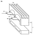
- it is an exploded perspective view for demonstrating the structure of the core in which fins were formed.
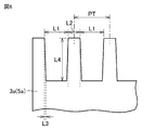
- it is a partially enlarged sectional view of a fin in a core.
- it is the second graph which shows the relationship between core loss and temperature.
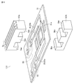
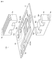
- FIG. 1 it is a circuit diagram concerning a DC-DC converter as a first example of a power converter. It is a top view which shows typically the structure of the 1st example of the electric power conversion apparatus which applied the cooling structure of a core in the same embodiment. In the same embodiment, it is sectional drawing in sectional line XI-XI shown in FIG. It is an exploded perspective view which shows the structure of the power conversion apparatus in the same embodiment. It is a top view which shows typically the structure of the 2nd example of the power conversion apparatus in the same embodiment. It is sectional drawing which shows the structure of the 3rd example of the power conversion apparatus in the same embodiment. It is sectional drawing which shows the structure of the 4th example of the power conversion apparatus in the same embodiment.
- FIG. 5 is an exploded perspective view showing another example of the structure of the core in the same embodiment.
- FIG. 5 is an exploded perspective view showing another example of the structure of the core of the power conversion device in the same embodiment. It is a top view which shows typically the structure of the 2nd example of the power conversion apparatus in the same embodiment. In the same embodiment, it is sectional drawing in sectional line XXXII-XXXII shown in FIG. It is sectional drawing which shows the structure of the 1st example of the power conversion apparatus which concerns on Embodiment 5 of this disclosure. In the same embodiment, it is an exploded perspective view which shows an example of the structure of the core of the power conversion apparatus. FIG.
- FIG. 5 is an exploded perspective view showing another example of the structure of the core of the power conversion device in the same embodiment. It is sectional drawing which shows the structure of the 2nd example of the power conversion apparatus in the same embodiment. It is sectional drawing which shows the structure of the 1st example of the power conversion apparatus which concerns on Embodiment 6 of this disclosure. It is sectional drawing which shows the structure of the 2nd example of the power conversion apparatus in the same embodiment. It is sectional drawing which shows the structure of the 3rd example of the power conversion apparatus in the same embodiment. It is sectional drawing which shows the structure of the 4th example of the power conversion apparatus in the same embodiment. It is sectional drawing which shows the structure of 5th example of the power conversion apparatus in the same embodiment.
- FIG. 1 It is a perspective view for demonstrating the structure of another upper core in the same embodiment.
- the power conversion device according to each embodiment it is a side view schematically showing the structure of a traveling device to which a power electronics device equipped with the power conversion device according to the seventh embodiment is attached.
- Embodiment 1 An example of the core cooling structure according to the first embodiment will be described.
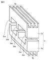
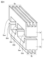
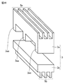
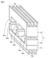
- the core cooling structure 1 includes a core 3 and a housing 11.
- the core 3 is attached to the housing 11.
- the core 3 includes an upper core 3a as a first core portion and a lower core 3b as a second core portion.
- the core 3 is mounted on the printed circuit board 31.
- the state in which the core 3 is mounted on the printed circuit board 31 also includes a state in which the printed circuit board 31 is assembled to the housing 11 with the core 3 attached to the housing 11.
- the printed circuit board 31 is arranged on the housing 11 with the support columns 41 interposed therebetween.
- As the support column 41 for example, an insulating resin spacer, a conductive metal spacer, or the like can be applied.
- a recess 13 is formed in the housing 11.
- the lower core 3b is fitted in the recess 13 with a TIM (Thermal Interface Material) material 19 interposed therebetween.
- the upper core 3a is, for example, an E type having the shape of the alphabet "E".
- the E-shaped upper core 3a has three legs 3aa.
- the lower core 3b is, for example, an I type having the shape of the alphabet "I”.
- the printed circuit board 31 is formed with a through hole 31a corresponding to the leg portion 3aa.
- the upper core 3a and the lower core 3b are arranged so as to face each other by inserting the leg portion 3aa into the through hole 31a and sandwiching the printed circuit board 31.
- a wiring pattern 33 wound around the core 3 is formed on the printed circuit board 31.
- the legs 3aa of the upper core 3a come into contact with the lower core 3b in a state where the core 3 is mounted on the printed circuit board 31.
- the upper core 3a is formed with fins 5a extending in one direction as the first heat radiation fins.
- a plurality of fins 5a are formed at intervals in the other direction intersecting with one direction.
- a closed magnetic path (see arrow) is formed in the core 3.
- the magnetic path is formed along the fins 5a extending in one direction and does not intersect the fins 5a. That is, the upper core 3a is formed with one or more fins 5a extending in one direction along the magnetic path.
- the distance L1 between the fins 5a and the fins 5a is set to, for example, 2 mm or more in the widest portion in order to take in the cooling air.
- the thickness L2 of the fin 5a is set to, for example, 1.4 mm or more in the narrowest portion in order to secure the strength of the core 3. From such a dimensional relationship, it is desirable that the pitch PT of the fins 5a is set to, for example, 2.7 mm or more.
- the height L4 of the fin 5a is set to, for example, 1.5 mm or more.
- the length L3 is 0.1 mm or more with respect to the height L4 of the fins 5a in consideration of the ease of taking out the fins 5a from the molding die.
- the gradient is set. That is, the fins 5a are not separate from the upper core 3a, but are integrally formed of the same material.
- increasing the width of the bottom portion limits the surface area of the core 3 having the fins 5a. Therefore, it is necessary to design the core 3 while considering the trade-off between the effective cross-sectional area of the fin 5a and the surface area of the core 3.
- the basic structure of the core cooling structure 1 is configured as described above.
- the core 3 includes an upper core 3a and a lower core 3b.
- the upper core 3a includes integrally formed fins 5a.
- the lower core 3b is attached to the recess 13 of the housing 11.
- the heat dissipation effect can be improved by providing, for example, a water cooling device or the like on the housing 11. Further, it is possible to perform a quantitative heat dissipation design based on the thermal conductivity of the core 3, the thermal conductivity of the TIM material 19, and the thermal conductivity of the housing 11 and the like.
- the fin 5a is formed so as to extend in the forward direction along the magnetic path. That is, the fins 5a are formed in the forward direction with respect to the magnetic flux. As a result, the fin 5a can also secure the cross-sectional area as the core on which the magnetic path is formed, and can obtain stable characteristics as, for example, a transformer or a reactor.
- the core is efficiently cooled, and it is not necessary to increase the physique (size) of the core 3 for cooling, so that the core is compact. It can contribute to the conversion. Further, since the fin 5a also becomes a part of the cross-sectional area of the core 3 in which the magnetic path is formed, the height of the upper core 3a can be reduced, which can contribute to the miniaturization of the core 3.
- the core 3 is efficiently cooled, the temperature change is suppressed, and stable characteristics can be obtained as a transformer or a reactor.
- the effect of suppressing a temperature change to obtain a stable core characteristic will be described using a graph of the core loss temperature characteristic listed in Non-Patent Document 1.
- the relationship between temperature and core loss is shown in FIGS. 7 and 8, respectively.
- the horizontal axis is temperature (° C).
- the vertical axis is the core loss (kW / m 3 ), which represents the magnetic core loss per unit volume.
- FIG. 7 is a graph showing the relationship between core loss and temperature when the magnetic flux density Bm of the magnetic field is 100 mT and the frequency is 200 kHz for each of the core materials BH1, BH2, and BH5.
- FIG. 8 is a graph showing the relationship between core loss and temperature when the magnetic flux density Bm of the magnetic field is 100 mT and the frequency is 500 kHz for each of the core materials BH1, BH2, and BH5.
- ferrite cores used in transformers and the like applied to power electronics equipment are often used at temperatures below 120 ° C. As shown in FIG. 7 or 8, the core loss tends to decrease as the core temperature rises. When the core temperature exceeds a certain temperature, the core loss increases. If the core loss tends to decrease as the temperature of the core rises, the core has a strong property (tolerance) against thermal runaway.
- the core cooling structure 1 by applying the above-mentioned core cooling structure 1 and setting the core temperature to be ⁇ 100 ° C. ( ⁇ -20 ° C.) or less, the core loss can be controlled at about 155 kW / m 3. It will be good.
- the core loss can be set to about 1200 kW / m 3 by performing a quantitative thermal design that can control the core temperature to about 90 ° C. ( ⁇ -30 ° C.). Furthermore, it is possible to design a mounting that can reduce the size of the core.
- the surface area of the core was emphasized in order to improve the heat dissipation of the core.
- FIG. 9 shows an example of a circuit diagram of the DC / DC converter.
- a DC / DC converter is a device that converts a DC power supply voltage input to an electronic device or the like into a required DC power supply voltage.
- the DC power supply voltage input to the DC / DC converter is converted into an AC voltage by, for example, a switching element 53 such as a MOSFET (Metal Oxide Semiconductor Field Effect Transistor).
- the power supply voltage converted into the AC voltage is converted into the AC voltage corresponding to the required power supply voltage by the transformer 57.
- the power supply voltage converted to the AC voltage is rectified by the diode 55 and output as the required DC power supply voltage.
- the core cooling structure 1 is applied to the power conversion device 51.
- the core 3 is mounted on the printed circuit board 31.
- the switching element, the diode 55, and the like are attached to the housing 11.
- the switching element 53 and the diode 55 are arranged so as to be sandwiched between the printed circuit board 31 and the housing 11.
- the core 3 of the transformer 57 includes an upper core 3a and a lower core 3b. Fins 5a are formed on the upper core 3a.
- Each of the upper core 3a and the lower core 3b is E-shaped.
- the upper core 3a and the lower core 3b are arranged so as to sandwich the printed circuit board 31, and the leg portion 3aa of the corresponding upper core 3a and the leg portion 3bb of the lower core 3b come into contact with each other through the through hole 31a.
- the lower core 3b is fitted in the recess 13 of the housing 11 with the TIM material 19 interposed therebetween.
- the windings constituting the core 3 of the transformer are composed of the wiring pattern 33 formed on the printed circuit board 31.
- the printed circuit board 31 employs a multilayer structure in which a plurality of printed circuit boards are stacked.
- the printed circuit board 31 is shown as one printed circuit board in order to avoid the complexity of the drawings.
- the primary winding (voltage V 1 , number of turns n 1 ) electrically connected to the switching element 53 is formed by a wiring pattern 33a.
- the wiring pattern 33a is formed on the upper printed circuit board and the middle (inner layer) printed circuit board. Electrically the attached secondary winding to the diode 55 (voltage V 2, the number of turns n 2) is constituted by a wiring pattern 33b.
- the wiring pattern 33b is formed on the printed circuit board of the lowermost layer and the printed circuit board of the middle layer (inner layer).
- a cooling flow path 21 as a heat radiating portion is formed in the housing 11. For example, cooling water is flowed through the cooling flow path 21.
- the cooling flow path 21 is arranged so that the cooling water flows in the region directly below the switching element 53, the region directly below the core 3, and the region directly below the diode 55.
- the cooling flow path 21 is connected to a cooling device 61 that cools the cooling water.
- fins 5a are formed in the upper core 3a, and the lower core 3b is attached to the recess 13 of the housing 11. Further, a cooling flow path 21 for cooling the switching element 53, the diode 55, and the core 3 is arranged in the housing 11, and the cooling water flows through the cooling flow path 21. As a result, the heat generated from the switching element 53, the diode 55, and the core 3 can be efficiently dissipated from the housing 11.
- a quantitative heat dissipation design can be performed based on the thermal conductivity of the core 3, the thermal conductivity of the TIM material 19, and the thermal conductivity of the housing 11.
- the core 3 can be quantitatively thermally designed, the size required for the core 3 can be reduced to the minimum necessary.
- the cooling flow path is provided in the housing 11 portion directly below the core 3 of the transformer. Does not have to be placed. Further, the wall thickness of the housing 11 may be the minimum necessary. Further, although the case where the cooling water is flowed through the cooling flow path 21, the case where the cooling water is flown is not limited to the cooling water, and a liquid to which a cooling oil or an antifreeze liquid is added may be flown. Further, the refrigerant used for the air conditioner or the like may be allowed to flow.
- a cooler 63 including a compressor 65, a decompression unit 67, and a recovery unit 69 is applied to the power conversion device 51 as a heat radiating unit.
- the cooler 63 has a path (cooling flow path 21) for supplying to the power conversion device 51 and a path for supplying to a normally used cooling device (not shown) other than the power conversion device 51 (see the double line arrow). ) Are connected in parallel. Since the other configurations are the same as the configurations of the power conversion device 51 shown in FIG. 10 and the like, the same members are designated by the same reference numerals, and the description thereof will not be repeated unless necessary.
- the high-temperature refrigerant compressed by the compressor 65 is radiated by the heat radiating unit 66 and then decompressed by the decompression unit 67.
- the reduced pressure and low temperature refrigerant sequentially cools the switching element 53, the core 3 and the diode 55.
- the refrigerant that has cooled the diode 55 is recovered by the recovery unit 69, and is compressed again by the compressor 65.
- this cycle will be repeated.
- heat generated from the switching element 53, the diode 55, and the core 3 can be efficiently transferred from the housing 11 via the refrigerant as in the case of the power conversion device 51 according to the first example. It can dissipate heat. Further, regarding the heat dissipation, a quantitative heat dissipation design can be performed based on the thermal conductivity of the core 3, the thermal conductivity of the TIM material 19, and the thermal conductivity of the housing 11 and the like.
- the cooler 63 has a path (cooling flow path 21) for supplying the power conversion device 51 and a path (see the double line arrow) for supplying the cooling device that is normally used. Although the case where is connected in parallel has been described, these routes may be connected in series.
- the housing 11 is provided with air-cooled fins 23.
- the switching element, the diode 55, and the like are attached to the housing 11.
- the switching element 53 and the diode 55 are arranged so as to be sandwiched between the printed circuit board 31 and the housing 11.
- the heat generated in the switching element 53, the diode 55, and the core 3 is conducted to the air-cooled fins 23 via the housing 11.
- the heat conducted to the air-cooled fins 23 is dissipated by natural air-cooling or forced air-cooling.
- the housing 11 since heat is accumulated in the housing 11 due to the specific heat, the housing 11 also functions as a heat spreader. Further, the heat generated in the core 3 is dissipated by the fins 5a.
- the housing 11 is provided with air-cooled fins 23.
- Surface mount switching elements, diodes (not shown) and the like are mounted on the printed circuit board 31.
- a TIM material 19a is sandwiched between the printed circuit board 31 and the housing 11.
- the heat generated in the switching element, the diode, the wiring (none of which is shown) or the like mounted on the printed circuit board 31 is conducted to the housing 11 via the printed circuit board 31 and the TIM material 19. To do.
- the heat conducted to the housing 11 is conducted to the air-cooled fins 23 and dissipated by natural air-cooling or forced air-cooling, as in the third example. Further, since heat is accumulated in the housing 11 due to the specific heat, the housing 11 also functions as a heat spreader. Further, the heat generated in the core 3 is dissipated by the fins 5a.
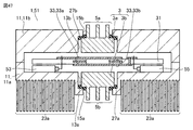
- Embodiment 2 (1st example) A first example of the power conversion device provided with the core cooling structure according to the second embodiment will be described. As shown in FIGS. 16, 17 and 18, the core cooling structure 1 is applied to the power conversion device 51. The core 3 is mounted on the printed circuit board 31. The switching element 53 and the diode 55 are arranged so as to be sandwiched between the printed circuit board 31 and the housing 11.
- the core 3 of the transformer 57 includes an upper core 3a and a lower core 3b. Fins 5a are formed on the upper core 3a. Fins 5b are formed on the lower core 3b.
- Each of the upper core 3a and the lower core 3b is E-shaped.
- the upper core 3a and the lower core 3b are arranged so as to sandwich the printed circuit board 31, and the leg portion 3aa of the corresponding upper core 3a and the leg portion 3bb of the lower core 3b come into contact with each other through the through hole 31a.
- the housing 11 is formed with a recess 13 corresponding to the shape of the lower core 3b including the fins 5b.
- the lower core 3b is fitted in the recess 13 of the housing 11. Since the other configurations are the same as those of the power conversion device 51 and the like shown in FIG. 1 and the like, the same members are designated by the same reference numerals, and the description thereof will not be repeated unless necessary.
- the housing 11 is formed with a recess 13 corresponding to the shape of the lower core 3b including the fins 5b. This facilitates the positioning of the core 3 including the lower core 3b, and facilitates the assembly of the power conversion device 51. Further, the contact area between the lower core 3b and the housing 11 is increased, and it is not always necessary to interpose the TIM material.
- the upper core 3a and the lower core 3b have the same shape, and it is possible to narrow down the mold for molding the core 3 to one. In addition, it is not necessary to manage two types of parts, which makes it possible to reduce costs and improve productivity.
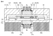
- the filler 29 is injected between the lower core 3b having the fins 5b and the housing 11.
- the filler 29 include a heat conductive resin or a potting material.
- the lower core 3b is fitted in the recess 13 of the housing 11 with the filler 29 interposed therebetween, so that the contact thermal resistance between the lower core 3b and the housing 11 can be lowered. As a result, the power conversion device 51 can be efficiently cooled.
- the TIM material 19a may be sandwiched between the printed circuit board 31 and the housing 11, for example, as shown in FIG. 15, and the printed circuit board 31 can be effectively cooled.
- Embodiment 3 (1st example) A first example of the power conversion device according to the third embodiment will be described. As shown in FIG. 20, in the power conversion device 51, the fins 5b of the lower core 3b are exposed from the housing 11. In addition to the recess 13, the housing 11 is formed with an opening 15 that penetrates the housing 11. As shown in FIG. 21, a stepped portion 17 is formed around the opening 15.
- the upper core 3a in the core 3 is E-type
- the lower core 3b is also E-type.
- the lower core 3b is provided with a portion where the fin 5b is not located, which abuts on the stepped portion 17.
- the fins 5b are exposed from the opening 15 in a state where the lower core 3b is placed on the stepped portion 17.
- the following effects can be obtained in addition to the effects of the power conversion device 51 described in the first embodiment.
- the fins 5b of the lower core 3b are exposed from the opening 15 of the housing 11.
- the core 3 can be forcibly air-cooled, and heat can be dissipated from the core 3 more effectively.
- the size of the core 3 can be reduced if the heat dissipation performance is the same, and a miniaturized transformer or reactor can be mounted on the power electronics device. Becomes possible. Further, it is not always necessary to interpose the TIM material between the housing 11 and the lower core 3b.
- cooling air that cools other semiconductor parts mounted on the power electronics equipment can be shared, it is possible to contribute to further miniaturization and cost reduction of the power electronics equipment.
- the core 3 As the core 3, the case where both the upper core 3a and the lower core 3b are E type is given as an example, but as shown in FIG. 24, the upper core 3a is E type and the lower core 3b is I type. It may be core 3.
- the number of fins 5a of the upper core 3a is four, whereas the number of fins 5b of the lower core 3b is three.
- the amount of heat radiated from the upper core 3a may exceed the amount of heat radiated from the lower core 3b.
- the amount of heat radiated from the upper core 3a may exceed the amount of heat radiated from the lower core 3b.
- the fins 5b of the lower core 3b are exposed from the housing 11 and forcibly air-cooled to promote heat dissipation from the fins 5b of the lower core 3b, thereby promoting heat dissipation from the upper core 3a. And the amount of heat radiated from the lower core 3b can be balanced.
- the shape including the number of fins 5a of the upper core 3a and the shape including the number of fins 5b of the lower core 3b may be the same shape. Even in this case, it is desirable to carry out the design after considering the balance between the amount of heat radiated from the upper core 3a and the amount of heat radiated from the lower core 3b.
- the mold for molding the core can be shared between the upper core 3a and the lower core 3b.
- a stepped portion 17 is formed around the opening 15.
- the cushioning material 20 covers the stepped portion 17 and is arranged in such a manner that the cushioning material 20 is slightly inserted inside the opening 15.
- the lower core 3b is arranged so as to sandwich the cushioning material 20 arranged so as to be slightly inserted inside the opening 15 between the housing 11 and the lower core 3b.
- the following effects can be obtained.
- the lower core 3b of the core 3 when the lower core 3b of the core 3 is attached to the opening 15 of the housing 11, the lower core 3b is provided by the cushioning material 20 arranged in a manner slightly inserted inside the opening 15. It can prevent damage.
- the cushioning material 20 When, for example, a TIM material is applied as the cushioning material 20, heat conduction from the core 3 to the housing 11 is promoted, which can contribute to heat dissipation. Further, as the cushioning material 20, a gasket can be applied. Further, a sheet-like rubber or resin material used for the O-ring, a joint sheet, a Teflon (registered trademark) sheet, or the like can also be applied. Further, for example, as shown in FIG. 15, the printed circuit board 31 can be cooled by interposing a TIM material between the printed circuit board 31 and the housing 11.
- Embodiment 4 (1st example) A first example of the power conversion device according to the fourth embodiment will be described. As shown in FIG. 28, in the power conversion device 51, a cooling flow path 21 is formed between the lower core 3b and the housing 11. For example, cooling water is flowed through the cooling flow path 21.
- the lower core 3b is arranged on the stepped portion 17 of the housing 11 with the sealing material 27 interposed therebetween.
- a lower core 3b having fins 5b is arranged in order to effectively dissipate heat.
- the lower core 3b may be an E type as shown in FIG. 29 or an I type as shown in FIG. 30.
- the core 3 will be directly cooled by the cooling water flowing through the cooling flow path 21.
- the sealing material 27 for example, a gasket or a TIM material can be applied.
- the following effects can be obtained.
- the heat generated in the core 3 is directly dissipated to the cooling water flowing through the cooling flow path 21 via the fins 5b of the lower core 3b. Thereby, high heat dissipation capacity can be obtained. Further, as a result, if the heat dissipation performance is the same, the size of the core 3 can be further reduced, and the miniaturized transformer or reactor can be mounted on the power electronics device.
- the cooling water that cools other semiconductor parts mounted on the power electronics equipment can be shared, it is possible to contribute to further miniaturization and cost reduction of the power electronics equipment. Further, since the core 3 can be directly cooled, heat can be dissipated by using another cooling environment arranged around the housing 11, which contributes to further miniaturization and cost reduction of the power electronics device. Can be done.
- the case where the cooling water is passed through the cooling flow path 21 has been described, the case is not limited to the cooling water, and a liquid to which a cooling oil or an antifreeze liquid is added may be allowed to flow. Further, the refrigerant used for the air conditioner or the like may be allowed to flow.
- the following effects can be obtained.
- the housing 11 in addition to the cooling flow path 21 for cooling the core 3, a cooling flow path 21 for cooling the switching element 53 and the diode 55 is arranged, and cooling water flows through the cooling flow path 21.
- the heat generated from the switching element 53, the diode 55, and the core 3 can be efficiently dissipated from the housing 11.
- a quantitative heat dissipation design can be performed based on the thermal conductivity of the core 3 and the thermal conductivity of the housing 11 and the like.
- the core 3 can be quantitatively thermally designed, the size required for the core 3 can be reduced to the minimum necessary.
- the case where the cooling water is passed through the cooling flow path 21 has been described, the case is not limited to the cooling water, and a liquid to which a cooling oil or an antifreeze liquid is added may be allowed to flow. Further, the refrigerant used for the air conditioner or the like may be allowed to flow. When a refrigerant is used, it is necessary to consider leakage of the refrigerant and, for example, secure structural strength for the adhesion between the sealing material 27 such as a gasket and the lower core 3b.
- sealing material 27 in addition to the gasket, for example, a rubber or resin material used for an O-ring in the form of a sheet, a joint sheet, a Teflon sheet, or the like can be applied.
- the cooling water may be flowed so that the switching element 53 is cooled first and then the core 3 is cooled.
- the printed circuit board 31 can be cooled by interposing a TIM material between the printed circuit board 31 and the housing 11.
- Embodiment 5 (1st example) A first example of the power conversion device according to the fifth embodiment will be described. As shown in FIG. 33, in the power conversion device 51, the fins 5b of the lower core 3b are exposed from the opening 15 of the housing 11. As shown in FIG. 34 or FIG. 35, an anticorrosion-treated portion 7b that has been subjected to an anticorrosion treatment is formed on the surface of the fin 5b.
- the anticorrosion treatment portion 7b is formed on the lower core 3b, for example, when the surface treatment is performed with a conductive material such as nickel plating, an induced current or an eddy current flows due to a magnetic field. For this reason, it is important not to perform surface treatment over the entire circumference of the lower core 3b in the direction intersecting the magnetic field.
- the surface treatment is not performed on the portion where the upper core 3a and the lower core 3b come into contact with each other. As shown in FIG. 34, the surface treatment is not performed on the portion where the leg portion 3aa and the leg portion 3bb are in contact with each other. As shown in FIG. 35, the surface treatment is not performed on the portion where the leg portion 3aa and the lower core 3b are in contact with each other.
- the anticorrosion treatment portion when the anticorrosion treatment portion is formed on the core 3 by the conductive material, the anticorrosion treatment portion corresponds to one winding of the transformer winding at the maximum, so that the voltage corresponding to the transformer winding ratio is the anticorrosion treatment portion. Will occur at the edge of. Therefore, it is necessary to arrange the untreated portion that does not form the anticorrosion treated portion so that the voltage of the anticorrosion treated portion becomes a voltage equal to or lower than the surface insulation voltage of the core 3.
- the following effects can be obtained in addition to the effects of the power conversion device 51 described in the third embodiment.
- the anticorrosive treatment portion 7b on the fins 5b of the lower core 3b, it is possible to have high resistance to the mixing of corrosive substances such as corrosive gas.
- the anticorrosion treatment unit 7b suppresses damage to the lower core 3b due to impact, which facilitates the handling of the core 3.
- a cooling flow path 21 is formed between the lower core 3b and the housing 11. For example, cooling water is flowed through the cooling flow path 21.
- an anticorrosion-treated portion 7b that has been subjected to an anticorrosion treatment is formed.
- the anticorrosion treatment unit 7b is formed only in the portion of the cooling flow path 21 that comes into contact with the cooling water so that the voltage of the anticorrosion treatment unit 7b is equal to or lower than the surface insulation voltage of the core 3.
- the following effects can be obtained in addition to the effects of the power conversion device 51 described in the fourth embodiment.
- the anticorrosive treatment portion 7b on the fins 5b of the lower core 3b, for example, it is possible to have high resistance to corrosive substances mixed in the cooling water.
- the anticorrosion treatment unit 7b suppresses damage to the lower core 3b due to impact, which facilitates the handling of the core 3. Further, chipping of the cooling flow path 21 portion is reduced, and the durability of the power conversion device 51 provided with the cooling structure 1 of the core 3 can be improved.
- the printed circuit board 31 is also cooled by interposing a TIM material between the printed circuit board 31 and the housing 11. be able to.
- Embodiment 6 a power conversion device including a lower housing to which the lower core is attached and an upper housing to which the upper core is attached will be described as the housing.
- the power conversion device 51 provided with the core cooling structure 1 includes a lower housing 11a and an upper housing 11b as the housing 11.
- the lower housing body 11a and the upper housing body 11b are arranged so as to sandwich the printed circuit board 31 and the core 3.
- a core 3 having no fins formed is applied.
- the lower core 3b is attached to the lower housing 11a.
- the lower core 3b is fitted in the recess 13a formed in the lower housing 11a with the TIM material 19a interposed therebetween.
- An upper core 3a is attached to the upper housing 11b.
- the upper core 3a is fitted in the recess 13b formed in the upper housing 11b with the TIM material 19b interposed therebetween.
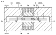
- FIG. 39 A third example of the power conversion device will be described. As shown in FIG. 39, in the power conversion device 51, fins 5a are formed in the upper core 3a. Fins 5b are formed on the lower core 3b. The lower core 3b is attached to the lower housing 11a. The upper core 3a is attached to the upper housing 11b.
- the lower core 3b is fitted into the recess 13a formed in the lower housing 11a.
- the upper core 3a is fitted in a recess 13b formed in the upper housing 11b. Since the other configurations are the same as those of the power conversion device 51 and the like shown in FIG. 16 and the like, the same members are designated by the same reference numerals, and the description thereof will not be repeated unless necessary.
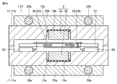
- FIG. 40 A fourth example of the power conversion device will be described.
- the lower core 3b is attached to the lower housing 11a.
- the lower core 3b is fitted in the recess 13a formed in the lower housing 11a with the filler 29a interposed therebetween.
- An upper core 3a is attached to the upper housing 11b.
- the upper core 3a is fitted in the recess 13b formed in the upper housing 11b with the filler 29b interposed therebetween.
- the core 3 includes an upper core 3a and a lower core 3b
- the housing 11 includes an upper housing 11b and a lower housing 11a.
- the lower core 3b is attached to the lower housing 11a.
- the upper core 3a is attached to the upper housing 11b.
- the air-cooled fins 23a and 23b described above can be applied to the power conversion device 51 shown in each of FIGS. 38 to 40 in addition to the power conversion device 51 shown in FIG. 37.
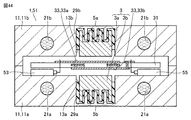
- FIG. 42 A sixth example of the power conversion device will be described. As shown in FIG. 42, water-cooled fins 25b are attached to the upper housing 11b. A water-cooled fin 25a is attached to the lower housing 11a. The water-cooled fin 25b is provided with a cooling flow path 26b. The water-cooled fin 25a is provided with a cooling flow path 26a.
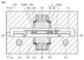
- FIG. 43 A seventh example of the power conversion device will be described. As shown in FIG. 43, a cooling flow path 21b is formed in the upper housing 11b. A cooling flow path 21a is formed in the lower housing 11a. Since the other configurations are the same as the configurations of the power conversion device 51 shown in FIG. 38, the same members are designated by the same reference numerals, and the description thereof will not be repeated unless necessary.
- FIG. 44 An eighth example of the power conversion device will be described. As shown in FIG. 44, a cooling flow path 21b is formed in the upper housing 11b. A cooling flow path 21a is formed in the lower housing 11a. Since the other configurations are the same as the configurations of the power conversion device 51 shown in FIG. 40, the same members are designated by the same reference numerals, and the description thereof will not be repeated unless necessary.
- FIG. 45 in the power conversion device 51, the lower core 3b is fitted into the recess 13a formed in the lower housing 11a with the sealing material 27a interposed therebetween.
- a cooling flow path 21a is formed between the lower core 3b and the lower housing 11a.
- a cooling flow path 21a is further formed in the lower housing 11a.
- the upper core 3a is fitted into the recess 13b formed in the upper housing 11b with the sealing material 27b interposed therebetween.
- a cooling flow path 21b is formed between the upper core 3a and the upper housing 11b. For example, cooling water is flowed through the cooling channels 21a and 21b. Since the other configurations are the same as the configurations of the power conversion device 51 shown in FIG. 22, the same members are designated by the same reference numerals, and the description thereof will not be repeated unless necessary.
- the anticorrosion treatment portion 7b is formed on the surface of the fins 5b of the lower core 3b.
- the anticorrosion treatment section 7b is formed in a portion of the fin 5b that comes into contact with the cooling water flowing through the cooling flow path 21a.
- An anticorrosion treatment portion 7a is formed on the surface of the fin 5a of the upper core 3a.
- the anticorrosion treatment section 7a is formed in a portion of the fin 5a that comes into contact with the cooling water flowing through the cooling flow path 21b. Since the other configurations are the same as the configurations of the power conversion device 51 shown in FIG. 45, the same members are designated by the same reference numerals, and the description thereof will not be repeated unless necessary.
- the power conversion devices according to the fifth to tenth examples described as variations of the power conversion devices having a cooling structure by air cooling or water cooling are the same as the effects of the corresponding power conversion devices 51 described in the first to sixth embodiments. The effect of can be obtained.
- cooling is efficiently performed, and for example, a TIM material is used as a filler to reduce the thermal resistance of the housing 11 in the lateral direction as much as possible to reduce the size of the housing 11.
- a TIM material is used as a filler to reduce the thermal resistance of the housing 11 in the lateral direction as much as possible to reduce the size of the housing 11.
- a simple TIM material such as a sheet or grease may be used instead of the TIM material as the filler.
- a cooling flow path may be further provided in a portion of the housing 11 in the vicinity of the core 3 (lower core 3b).
- the cooling flow path 21 is not limited to the cooling water, and a liquid to which a cooling oil or an antifreeze liquid is added may flow. Further, the refrigerant used for the air conditioner or the like may be allowed to flow. Further, for example, as shown in FIG. 15, the printed circuit board 31 can be cooled by interposing a TIM material between the printed circuit board 31 and the housing 11.
- Embodiment 7 (1st example) A first example of the power conversion device according to the seventh embodiment will be described.
- the lower core 3b is attached to the lower housing 11a with the sealing material 27a interposed therebetween.
- the fins 5b of the lower core 3b are exposed from the lower housing 11a.
- the lower housing 11a is formed with an opening 15a that penetrates the lower housing 11a.
- the fins 5b are exposed from the opening 15a.
- the lower housing 11a is provided with air-cooled fins 23a.
- the upper core 3a is attached to the upper housing 11b with the sealing material 27b interposed therebetween.
- the fins 5a of the upper core 3a are exposed from the upper housing 11b.
- the upper core 3a is formed with an opening 15b that penetrates the upper housing 11b.
- the fins 5a are exposed from the opening 15b. Since the other configurations are the same as the configurations of the power conversion device 51 shown in FIG. 25 and the like, the same members are designated by the same reference numerals, and the description thereof will not be repeated unless necessary.
- both the fins 5a of the upper core 3a and the fins 5b of the lower core 3b are exposed from the housing 11.
- the divided upper core 3a and lower core 3b can be cooled to the same extent, and the core 3 (transformer) can be further miniaturized.
- the core 3 it can be used in a region where the characteristics are stable.
- air-cooled fins may also be provided on the upper housing 11b.
- anticorrosion-treated portions 7a and 7b are formed on the respective surfaces of the exposed fins 5a and 5b. As a result, for example, it is possible to have strong resistance even in an environment where corrosive gas may be generated.
- printing is performed by interposing a TIM material between the printed circuit board 31 and the housing 11.
- the substrate 31 can also be cooled.
- a third example of the power conversion device according to the seventh embodiment will be described.
- the length of the air-cooled fins 23a extending downward is different from the length of the air-cooled fins 23a in the power conversion device according to the first example.
- the air-cooled fins 23a are formed so as to be located above the lower ends of the fins 5b.
- the power conversion device 51 since the air-cooled fins 23a are located above the lower ends of the fins 5b, the power conversion device 51 can be miniaturized in addition to the cooling effect.
- a fourth example of the power conversion device according to the seventh embodiment will be described.
- the length of the air-cooled fins 23a extending downward is different from the length of the air-cooled fins 23a in the power conversion device according to the second example.
- the air-cooled fins 23a are formed so as to be located above the lower ends of the fins 5b.
- the power conversion device 51 since the air-cooled fins 23a are located above the lower ends of the fins 5b, the power conversion device 51 can be miniaturized in addition to the cooling effect.
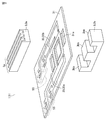
- the core 3 includes an upper core 3a and a lower core 3b.
- the upper core 3a is an I type having the shape of the alphabet "I”.
- the lower core 3b is an E type having the shape of the alphabet "E”.
- the E-shaped lower core 3b has three legs 3bb.
- the printed circuit board 31 is formed with a through hole 31a corresponding to the leg portion 3bb.
- the upper core 3a and the lower core 3b are arranged so as to face each other by inserting the leg portion 3bb into the through hole 31a and sandwiching the printed circuit board 31. Since the configuration other than this is the same as the configuration of the power conversion device 51 shown in FIGS. 1 to 3, etc., the same members shall be designated by the same reference numerals, and the description thereof shall not be repeated unless necessary. To do.
- fins 5a are formed on the I-type upper core 3a.
- the lower core 3b is in contact with the housing 11 (see FIG. 2 and the like). Further, the lower core 3b is fitted into the housing 11 via the TIM material 19 (see FIG. 2 and the like). As a result, the heat of the lower core 3b is dissipated by the housing 11. As a result, the heat of the core 3 is efficiently dissipated, and the core 3 can be cooled.
- the fins 5a extend in one direction along the magnetic path.
- the fin 5a can secure the cross-sectional area as the core on which the magnetic path is formed, and can obtain stable characteristics as, for example, a transformer or a reactor. ..
- the core is formed by compacting a granular material of several hundred ⁇ m or less, such as a dascoto core or a ferrite core, into a desired shape and sintering it. Therefore, the productivity of the core is relatively good.
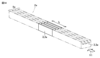
- the I-shaped upper core 3a extends in one direction, and the cross-sectional shape as the first cross-sectional shape along the other direction intersecting with one direction is the upper core 3a extending in one direction. It has the same shape over the entire length of.
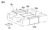
- the E-shaped lower core 3b extends in another direction, and the cross-sectional shape as the second cross-sectional shape along one direction is the same over the entire length of the lower core 3b extending in the other direction. ..
- the same shape is not intended to be geometrically (mathematical) identical, and includes, for example, manufacturing errors.
- each of the upper core 3a and the lower core can be manufactured by compression molding in which the material is compressed along one direction.
- it can be manufactured by extrusion molding in which a material is extruded along one direction.
- a mold for molding the upper core (not shown) and a mold for molding the lower core (not shown) are filled with a granular material.
- the upper core 3a is formed by compressing the granular material filled in the mold serving as the upper core in the direction indicated by the arrow Y1.
- the lower core 3b is formed by compressing the granular material filled in the mold serving as the lower core in the direction indicated by the arrow Y2.
- the formed upper core 3a and lower core 3b are baked to complete the upper core 3a and the lower core 3b.
- the manufacturing method by extrusion molding will be described.
- the granular material is filled into an extrusion mold (not shown) that forms a molded body as an upper core. Further, the granular material is filled in an extrusion mold (not shown) for molding the molded product as the lower core.
- the compact is extruded from each extrusion mold while applying pressure (arrow Y1: see FIG. 54, arrow Y2: see FIG. 55).
- an I-shaped molded body 2a serving as the upper core 3a having the same cross-sectional shape in the direction intersecting the extrusion direction over the entire length is formed.
- an E-shaped molded body 2b serving as the lower core 3b having the same cross-sectional shape in the direction intersecting the extrusion direction over the entire length is formed.
- the upper core 3a is formed by cutting the I-shaped molded body 2a to a desired length L.
- the lower core 3b is formed by cutting the E-shaped molded body 2b to a desired length L.
- the upper core 3a and the lower core 3b are completed by baking the upper core 3a and the lower core 3b cut to the desired length L, respectively.
- the upper core 3a and the lower core 3b can be formed by compressing the material filled in the mold in one direction, the productivity is improved, and the production of the core 3 is performed. The cost can be reduced.
- the length of cutting the molded product can be applied to the upper core or lower core with different specifications.
- the extrusion type can be shared, and investment in production equipment can be suppressed.
- the ease of taking out the fins 5a (draft) required in the manufacturing method by compression molding or the manufacturing method by extrusion molding is as described in FIG. Further, the core 3 described in the first embodiment and the like can be easily manufactured by compression from two directions.
- the upper core 3a shown in FIG. 3 when the upper core 3a shown in FIG. 3 is manufactured, it can be manufactured by compressing it in the direction indicated by the arrow Y3 and the direction indicated by the arrow Y4 as shown in FIG. 56.
- the direction indicated by the arrow Y3 is a direction that intersects the direction in which the fins 5a extend, and is a direction in which the fins 5a are compression-molded.
- the direction indicated by the arrow Y4 is the direction in which the upper core 3a having the leg portion 3aa extends.
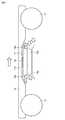
- a power electronics device 71 equipped with a power conversion device 51 is attached to a traveling device 73 having wheels 77.
- the fins 5a and 5b (see FIGS. 47 to 50) and the air-cooled fins 23a of the core 3 of the power conversion device 51 are exposed.
- Air passage guides 75a and 75b are arranged around the power electronics device 71.
- the traveling device 73 travels (see the right-pointing arrow)
- the air passage guides 75a and 75b guide air (see the left-pointing arrow) to the fins 5a and 5b and the air-cooled fins 23a.
- the cross-sectional area of the area between the air passage guide 75a and the traveling device 73 where the power electronics device 71 is arranged is the entrance of the air passage guide 75a. It is small compared to the cross-sectional area of the side and exit side.
- the velocity of the air flowing through the region where the power electronics device 71 is arranged becomes faster than the velocity of the air flowing through the respective regions of the inlet side and the outlet side of the air passage guide 75a.
- the region where the power electronics device 71 is arranged becomes a negative pressure, air is easily sucked in, and the power conversion device 51 is effectively cooled.
- a mounting mode of the power electronics device 71 to the traveling device 73 As a mounting mode of the power electronics device 71 to the traveling device 73, a mounting mode in which the entire power electronics device 71 is exposed without providing the air passage guide 75a or the like is also possible.
- the shape of the suction port and the shape of the discharge port should be the same so that the same cooling effect can be obtained for the bidirectional movement of the traveling device 73. Is desirable.
- the present invention is effectively used in a power conversion device to which a core as a magnetic circuit component is applied.
Landscapes
- Engineering & Computer Science (AREA)
- Power Engineering (AREA)
- Dc-Dc Converters (AREA)
- Transformer Cooling (AREA)
- Cooling Or The Like Of Electrical Apparatus (AREA)
Priority Applications (2)
| Application Number | Priority Date | Filing Date | Title |
|---|---|---|---|
| JP2021540684A JP7195445B2 (ja) | 2019-08-22 | 2020-07-22 | コアの冷却構造およびそれを備えた電力変換装置 |
| US17/626,136 US20220277882A1 (en) | 2019-08-22 | 2020-07-22 | Core cooling structure and power conversion device including the same |
Applications Claiming Priority (2)
| Application Number | Priority Date | Filing Date | Title |
|---|---|---|---|
| JP2019151844 | 2019-08-22 | ||
| JP2019-151844 | 2019-08-22 |
Publications (1)
| Publication Number | Publication Date |
|---|---|
| WO2021033485A1 true WO2021033485A1 (ja) | 2021-02-25 |
Family
ID=74660862
Family Applications (1)
| Application Number | Title | Priority Date | Filing Date |
|---|---|---|---|
| PCT/JP2020/028424 Ceased WO2021033485A1 (ja) | 2019-08-22 | 2020-07-22 | コアの冷却構造およびそれを備えた電力変換装置 |
Country Status (3)
| Country | Link |
|---|---|
| US (1) | US20220277882A1 (https=) |
| JP (1) | JP7195445B2 (https=) |
| WO (1) | WO2021033485A1 (https=) |
Cited By (3)
| Publication number | Priority date | Publication date | Assignee | Title |
|---|---|---|---|---|
| KR20230126921A (ko) * | 2022-02-24 | 2023-08-31 | 가천대학교 산학협력단 | 평면 변압기 및 그 제조 방법 |
| WO2024224955A1 (ja) * | 2023-04-28 | 2024-10-31 | 三菱電機株式会社 | 電力変換装置 |
| CN120090032A (zh) * | 2024-12-31 | 2025-06-03 | 武汉光谷航天三江激光产业技术研究院有限公司 | 梯级变压式微通道散热结构及高功率激光器截止光阑 |
Families Citing this family (1)
| Publication number | Priority date | Publication date | Assignee | Title |
|---|---|---|---|---|
| CN115172021B (zh) * | 2022-09-08 | 2022-12-02 | 深圳市固电电子有限公司 | 电感器冷却系统及方法 |
Citations (5)
| Publication number | Priority date | Publication date | Assignee | Title |
|---|---|---|---|---|
| JPS5495864U (https=) * | 1977-12-20 | 1979-07-06 | ||
| JPH0277105A (ja) * | 1987-07-14 | 1990-03-16 | Hitachi Metals Ltd | 磁心部品 |
| JP2007298066A (ja) * | 2006-04-28 | 2007-11-15 | Mitsubishi Electric Corp | 電磁式燃料噴射弁 |
| JP2015095502A (ja) * | 2013-11-11 | 2015-05-18 | Fdk株式会社 | 巻線部品の取付構造 |
| WO2018037690A1 (ja) * | 2016-08-22 | 2018-03-01 | 三菱電機株式会社 | 電力変換装置 |
Family Cites Families (3)
| Publication number | Priority date | Publication date | Assignee | Title |
|---|---|---|---|---|
| JP2006019418A (ja) * | 2004-06-30 | 2006-01-19 | Mitsumi Electric Co Ltd | コイル装置 |
| WO2009051057A1 (ja) * | 2007-10-16 | 2009-04-23 | Tamura Corporation | フェライトコア |
| CN107615414B (zh) * | 2015-05-29 | 2020-08-11 | Ntn株式会社 | 磁性元件 |
-
2020
- 2020-07-22 WO PCT/JP2020/028424 patent/WO2021033485A1/ja not_active Ceased
- 2020-07-22 JP JP2021540684A patent/JP7195445B2/ja active Active
- 2020-07-22 US US17/626,136 patent/US20220277882A1/en not_active Abandoned
Patent Citations (5)
| Publication number | Priority date | Publication date | Assignee | Title |
|---|---|---|---|---|
| JPS5495864U (https=) * | 1977-12-20 | 1979-07-06 | ||
| JPH0277105A (ja) * | 1987-07-14 | 1990-03-16 | Hitachi Metals Ltd | 磁心部品 |
| JP2007298066A (ja) * | 2006-04-28 | 2007-11-15 | Mitsubishi Electric Corp | 電磁式燃料噴射弁 |
| JP2015095502A (ja) * | 2013-11-11 | 2015-05-18 | Fdk株式会社 | 巻線部品の取付構造 |
| WO2018037690A1 (ja) * | 2016-08-22 | 2018-03-01 | 三菱電機株式会社 | 電力変換装置 |
Cited By (4)
| Publication number | Priority date | Publication date | Assignee | Title |
|---|---|---|---|---|
| KR20230126921A (ko) * | 2022-02-24 | 2023-08-31 | 가천대학교 산학협력단 | 평면 변압기 및 그 제조 방법 |
| KR102584360B1 (ko) * | 2022-02-24 | 2023-10-05 | 가천대학교 산학협력단 | 평면 변압기 및 그 제조 방법 |
| WO2024224955A1 (ja) * | 2023-04-28 | 2024-10-31 | 三菱電機株式会社 | 電力変換装置 |
| CN120090032A (zh) * | 2024-12-31 | 2025-06-03 | 武汉光谷航天三江激光产业技术研究院有限公司 | 梯级变压式微通道散热结构及高功率激光器截止光阑 |
Also Published As
| Publication number | Publication date |
|---|---|
| US20220277882A1 (en) | 2022-09-01 |
| JP7195445B2 (ja) | 2022-12-23 |
| JPWO2021033485A1 (https=) | 2021-02-25 |
Similar Documents
| Publication | Publication Date | Title |
|---|---|---|
| JP7195445B2 (ja) | コアの冷却構造およびそれを備えた電力変換装置 | |
| US9466415B2 (en) | Reactor provided with a cooler | |
| JP7126600B2 (ja) | 電力変換装置およびコイル装置 | |
| JP7373915B2 (ja) | 電力変換装置 | |
| CN111344821B (zh) | 电力转换装置 | |
| US20220264769A1 (en) | Power converter and method for manufacturing power converter | |
| JP2011103395A (ja) | 発熱部品の放熱構造及びこの放熱構造を有している回路装置 | |
| JP6956484B2 (ja) | コイル装置および電力変換装置 | |
| JP7345621B2 (ja) | 電力変換装置および電力変換装置の製造方法 | |
| JP2012110207A (ja) | 電力変換装置 | |
| US11094452B2 (en) | Power converter | |
| CN102947901A (zh) | 电抗器 | |
| JP2013150414A (ja) | トランス及びスイッチング電源装置 | |
| CN113519114A (zh) | 电力变换装置 | |
| CN112789697B (zh) | 电抗器 | |
| US20100148909A1 (en) | High energy density inductor | |
| JP2023083520A (ja) | トランス | |
| CN107710578B (zh) | 电力变换装置 | |
| US20240387318A1 (en) | Semiconductor device | |
| CN112863815B (zh) | 电力转换装置 | |
| US20130299131A1 (en) | Adjustable heat dissipation assembly for magnetic devices | |
| WO2019235430A1 (ja) | 電力変換装置 | |
| JPWO2019138861A1 (ja) | コイル装置および電力変換装置 | |
| WO2017170184A1 (ja) | 電力変換装置 | |
| JP2025018450A (ja) | 電力変換装置 |
Legal Events
| Date | Code | Title | Description |
|---|---|---|---|
| 121 | Ep: the epo has been informed by wipo that ep was designated in this application |
Ref document number: 20855553 Country of ref document: EP Kind code of ref document: A1 |
|
| ENP | Entry into the national phase |
Ref document number: 2021540684 Country of ref document: JP Kind code of ref document: A |
|
| NENP | Non-entry into the national phase |
Ref country code: DE |
|
| 122 | Ep: pct application non-entry in european phase |
Ref document number: 20855553 Country of ref document: EP Kind code of ref document: A1 |