WO2021029331A1 - 制御装置、駆動装置、電動パワーステアリング装置及び制御方法 - Google Patents
制御装置、駆動装置、電動パワーステアリング装置及び制御方法 Download PDFInfo
- Publication number
- WO2021029331A1 WO2021029331A1 PCT/JP2020/030254 JP2020030254W WO2021029331A1 WO 2021029331 A1 WO2021029331 A1 WO 2021029331A1 JP 2020030254 W JP2020030254 W JP 2020030254W WO 2021029331 A1 WO2021029331 A1 WO 2021029331A1
- Authority
- WO
- WIPO (PCT)
- Prior art keywords
- torque
- signal
- oversampling
- assist torque
- control device
- Prior art date
- Legal status (The legal status is an assumption and is not a legal conclusion. Google has not performed a legal analysis and makes no representation as to the accuracy of the status listed.)
- Ceased
Links
Images


Classifications
-
- B—PERFORMING OPERATIONS; TRANSPORTING
- B62—LAND VEHICLES FOR TRAVELLING OTHERWISE THAN ON RAILS
- B62D—MOTOR VEHICLES; TRAILERS
- B62D6/00—Arrangements for automatically controlling steering depending on driving conditions sensed and responded to, e.g. control circuits
-
- B—PERFORMING OPERATIONS; TRANSPORTING
- B62—LAND VEHICLES FOR TRAVELLING OTHERWISE THAN ON RAILS
- B62D—MOTOR VEHICLES; TRAILERS
- B62D5/00—Power-assisted or power-driven steering
- B62D5/04—Power-assisted or power-driven steering electrical, e.g. using an electric servo-motor connected to, or forming part of, the steering gear
- B62D5/0457—Power-assisted or power-driven steering electrical, e.g. using an electric servo-motor connected to, or forming part of, the steering gear characterised by control features of the drive means as such
- B62D5/046—Controlling the motor
-
- B—PERFORMING OPERATIONS; TRANSPORTING
- B62—LAND VEHICLES FOR TRAVELLING OTHERWISE THAN ON RAILS
- B62D—MOTOR VEHICLES; TRAILERS
- B62D5/00—Power-assisted or power-driven steering
- B62D5/04—Power-assisted or power-driven steering electrical, e.g. using an electric servo-motor connected to, or forming part of, the steering gear
- B62D5/0457—Power-assisted or power-driven steering electrical, e.g. using an electric servo-motor connected to, or forming part of, the steering gear characterised by control features of the drive means as such
- B62D5/0481—Power-assisted or power-driven steering electrical, e.g. using an electric servo-motor connected to, or forming part of, the steering gear characterised by control features of the drive means as such monitoring the steering system, e.g. failures
-
- H—ELECTRICITY
- H02—GENERATION; CONVERSION OR DISTRIBUTION OF ELECTRIC POWER
- H02P—CONTROL OR REGULATION OF ELECTRIC MOTORS, ELECTRIC GENERATORS OR DYNAMO-ELECTRIC CONVERTERS; CONTROLLING TRANSFORMERS, REACTORS OR CHOKE COILS
- H02P23/00—Arrangements or methods for the control of AC motors characterised by a control method other than vector control
- H02P23/14—Estimation or adaptation of motor parameters, e.g. rotor time constant, flux, speed, current or voltage
-
- H—ELECTRICITY
- H02—GENERATION; CONVERSION OR DISTRIBUTION OF ELECTRIC POWER
- H02P—CONTROL OR REGULATION OF ELECTRIC MOTORS, ELECTRIC GENERATORS OR DYNAMO-ELECTRIC CONVERTERS; CONTROLLING TRANSFORMERS, REACTORS OR CHOKE COILS
- H02P29/00—Arrangements for regulating or controlling electric motors, appropriate for both AC and DC motors
-
- H—ELECTRICITY
- H02—GENERATION; CONVERSION OR DISTRIBUTION OF ELECTRIC POWER
- H02P—CONTROL OR REGULATION OF ELECTRIC MOTORS, ELECTRIC GENERATORS OR DYNAMO-ELECTRIC CONVERTERS; CONTROLLING TRANSFORMERS, REACTORS OR CHOKE COILS
- H02P29/00—Arrangements for regulating or controlling electric motors, appropriate for both AC and DC motors
- H02P29/50—Reduction of harmonics
-
- B—PERFORMING OPERATIONS; TRANSPORTING
- B62—LAND VEHICLES FOR TRAVELLING OTHERWISE THAN ON RAILS
- B62D—MOTOR VEHICLES; TRAILERS
- B62D5/00—Power-assisted or power-driven steering
- B62D5/04—Power-assisted or power-driven steering electrical, e.g. using an electric servo-motor connected to, or forming part of, the steering gear
- B62D5/0457—Power-assisted or power-driven steering electrical, e.g. using an electric servo-motor connected to, or forming part of, the steering gear characterised by control features of the drive means as such
- B62D5/046—Controlling the motor
- B62D5/0463—Controlling the motor calculating assisting torque from the motor based on driver input
-
- B—PERFORMING OPERATIONS; TRANSPORTING
- B62—LAND VEHICLES FOR TRAVELLING OTHERWISE THAN ON RAILS
- B62D—MOTOR VEHICLES; TRAILERS
- B62D5/00—Power-assisted or power-driven steering
- B62D5/04—Power-assisted or power-driven steering electrical, e.g. using an electric servo-motor connected to, or forming part of, the steering gear
- B62D5/0457—Power-assisted or power-driven steering electrical, e.g. using an electric servo-motor connected to, or forming part of, the steering gear characterised by control features of the drive means as such
- B62D5/046—Controlling the motor
- B62D5/0472—Controlling the motor for damping vibrations
-
- H—ELECTRICITY
- H02—GENERATION; CONVERSION OR DISTRIBUTION OF ELECTRIC POWER
- H02P—CONTROL OR REGULATION OF ELECTRIC MOTORS, ELECTRIC GENERATORS OR DYNAMO-ELECTRIC CONVERTERS; CONTROLLING TRANSFORMERS, REACTORS OR CHOKE COILS
- H02P2101/00—Special adaptation of control arrangements for generators
- H02P2101/45—Special adaptation of control arrangements for generators for motor vehicles, e.g. car alternators
Definitions
- the present invention relates to a control device that controls the drive of an electric power steering device, a drive device that is controlled by this control device, an electric power steering device provided with this drive device, and a control method.
- the motor of an electric power steering device which is considered to have little torque ripple, generates a torque ripple of about 0.2 Nm, and in recent years, a higher level that suppresses the torque ripple to the order of 0.01 Nm has been required.
- a method of reducing the torque ripple described above there is a method of improving the structure of the motor or a method of improving the control technique.
- Patent Document 1 discloses an electric power steering device that performs current feedback control by improving the control technique in order to reduce torque ripple.
- the electric power steering device of Patent Document 1 reduces torque ripple by a notch filter that removes a specific frequency component included in a control signal generated based on an actual current value.
- Patent Document 1 may not be able to meet the recent high demand level for suppressing torque ripple.
- An object of the present invention is to provide a control device, a drive device, an electric power steering device, and a control method capable of reducing torque ripple and realizing comfortable driving for a driver.
- the control device is a control device that controls an electric power steering device, and performs oversampling processing on a steering torque signal corresponding to steering torque, and steering torque over obtained by the oversampling processing. It has an oversampling code extension unit that obtains steering torque after code expansion by moving averaging processing that weights the sampling signal, and a base assist control unit that obtains base assist torque based on the coded expansion steering torque.
- the drive device includes the above-mentioned control device and an electric motor driven by the control device.
- the electric power steering device includes the above-mentioned control device, an electric motor driven by the control device, and an electric power steering mechanism driven by the electric motor.
- the control method according to the present invention is a control method for controlling an electric power steering device, in which a step of performing oversampling processing on a steering torque signal corresponding to steering torque and a steering torque obtained by the oversampling processing are performed. It has a step of obtaining a steering torque after code expansion by a moving averaging process that weights an oversampling signal, and a step of obtaining a base assist torque based on the steering torque after code expansion.
- torque ripple can be reduced to realize comfortable driving for the driver.
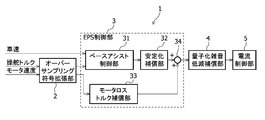
- Control device configuration The configuration of the control device 1 according to the embodiment of the present invention will be described in detail below with reference to FIG.
- the control device 1 controls the drive of the electric power steering mechanism described later.
- the control device 1 includes an oversampling code extension unit 2, an EPS control unit 3, a quantization noise reduction compensation unit 4, and a current control unit 5.
- EPS is an abbreviation for Electric Power Steering.
- the oversampling code extension unit 2 executes oversampling code extension processing for each of the steering torque signal corresponding to the input steering torque and the motor speed signal corresponding to the motor speed, and the sign extension-posted steering torque signal. And after sign extension, the motor speed signal is obtained.
- the oversampling code extension unit 2 outputs the obtained code extension-post-steering torque signal to the base assist control unit 31 of the EPS control unit 3, and outputs the obtained code-extension-post motor speed signal to the motor loss of the EPS control unit 3. Output to the torque compensation unit 33.
- the EPS control unit 3 is an electric power steering device based on a vehicle speed signal according to the input vehicle speed, a sign-extended steering torque signal and a code-extended motor speed signal input from the oversampling code extension unit 2. Assist torque is obtained, and control is performed to compensate for the obtained assist torque.
- the EPS control unit 3 includes a base assist control unit 31, a stabilization compensation unit 32, a motor loss torque compensation unit 33, and an adder 34.
- the base assist control unit 31 obtains the base assist torque based on the input vehicle speed signal and the sign extension post-steering torque signal input from the oversampling code extension unit 2.
- the base assist control unit 31 stores, for example, a table in which the vehicle speed, the steering torque, and the base assist torque are associated with each other in advance. With reference to this table, the vehicle speed indicated by the input vehicle speed signal and the oversampling code extension The base assist torque associated with the steering torque indicated by the sign-extended steering torque signal input from the unit 2 is obtained.
- the base assist control unit 31 outputs a base assist torque signal corresponding to the base assist torque thus obtained to the stabilization compensation unit 32.
- the stabilization compensation unit 32 performs phase compensation by combining a plurality of phase lead compensation and phase delay compensation with respect to the base assist torque signal input from the base assist control unit 31.
- the frequency characteristic of the phase compensation is dynamically changed according to the steering state and the traveling vehicle speed.
- the stabilization process is executed to obtain the assist torque of the electric power steering device, and the assist torque signal corresponding to the obtained assist torque is output to the adder 34.
- the motor loss torque compensation unit 33 obtains a motor loss torque compensation torque that compensates for the assist torque of the electric motor based on the code extension post-motor speed signal input from the oversampling code extension unit 2.
- the motor loss torque compensation unit 33 outputs a motor loss torque compensation torque signal corresponding to the obtained motor loss torque compensation torque to the adder 34. The details of the configuration of the motor loss torque compensation unit 33 will be described later with reference to FIG.
- the adder 34 adds the assist torque of the assist torque signal input from the stabilization compensation unit 32 and the motor loss torque compensation torque of the motor loss torque compensation torque signal input from the motor loss torque compensation unit 33. It is a torque compensation unit that compensates for the assist torque.
- the adder 34 outputs an assist torque signal corresponding to the compensated assist torque to the quantization noise reduction compensation unit 4.
- the quantization noise reduction compensation unit 4 reduces the quantization error included in the assist torque signal input from the adder 34 by an IIR filter or the like, and outputs the assist torque signal with the reduced quantization error to the current control unit 5. .. IIR is an abbreviation for Infinity Impulse Response.
- the current control unit 5 calculates the drive current of the electric motor based on the assist torque signal input from the quantization noise reduction compensation unit 4.
- the drive current calculated by the current control unit 5 is output to an electric motor (not shown), and the electric motor drives the electric power steering device.
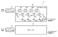
- the oversampling code extension unit 2 includes an oversampling unit 21, an FIR filter 22, an oversampling unit 23, and an FIR filter 24.
- the oversampling unit 21 oversamples the input analog signal or digital signal, which is a steering torque signal, to generate a digital signal, which is a steering torque oversampling signal, and outputs the generated steering torque oversampling signal to the FIR filter 22. To do.
- the oversampling unit 21 oversamples the steering torque signal with a cycle faster than the control cycle when controlling the assist torque. For example, the oversampling cycle is 200 ⁇ sec when the control cycle for controlling the assist torque is 1 msec.
- the FIR filter 22 controls the gain and phase of the steering torque oversampling signal by executing a moving average process (weighted moving average process) that weights the steering torque oversampling signal input from the oversampling unit 21. After sign extension, a steering torque signal is obtained. The FIR filter 22 outputs the obtained sign-extended steering torque signal to the base assist control unit 31.
- a moving average process weighted moving average process
- the oversampling unit 23 oversamples the input motor speed signal to generate a motor speed oversampling signal, and outputs the generated motor speed oversampling signal to the FIR filter 24.
- the oversampling unit 23 oversamples the motor speed signal with a cycle faster than the control cycle when controlling the assist torque. For example, the oversampling cycle is 200 ⁇ sec when the control cycle for controlling the assist torque is 1 msec.
- the FIR filter 24 controls the gain and phase of the motor speed oversampling signal by executing a moving average process that weights the motor speed oversampling signal input from the oversampling unit 23, and the sign-extended motor speed. Get a signal.
- the FIR filter 24 outputs the obtained code-extended motor speed signal to the motor loss torque compensation unit 33.
- the FIR filter 22 and the FIR filter 24 have the same configuration, and the multiplier 221 and the register 222, the multiplier 223, the adder 224, the register 225, the multiplier 226, the adder 227, the register 228, and the multiplier 229. , Adder 230, register 231 and multiplier 232, adder 233 and multiplier 234.
- all the registers, multipliers and adders included in the FIR filters 22 and 24 are not shown.
- "! written between registers 225 and 228 indicates that there is a predetermined number of registers between registers 225 and 228.
- the "! between the multipliers 226 and 229 also indicates that there is a predetermined number of multipliers between the multipliers 226 and 229.
- the "" between the adders 227 and 230 also indicates that there is a predetermined number of multipliers between the adders 227 and 230.
- the multiplier 221 outputs the weighting coefficients h 0 to the adder 224 multiplies the input signal x [n] from the oversampling section 21 or oversampling 23.
- the register 222 adds a delay of one sampling cycle to the input signal x [n] from the oversampling unit 21 or the oversampling 23, and outputs the signal to the multiplier 223 and the register 225.
- the multiplier 223 multiplies the output signal of the register 222 by the weighting coefficient h 1 and outputs the output signal to the adder 224.
- the adder 224 adds the output signal of the multiplier 221 and the output signal of the multiplier 223 and outputs the sum to the adder 227.
- Register 225 adds a delay of one sampling cycle to the output signal of register 222 and outputs it to the multiplier 226 and a register in the subsequent stage (not shown).
- the multiplier 226 multiplies the output signal of the register 225 by the weighting coefficient h 2 and outputs the output signal to the adder 227.
- the adder 227 adds the output signal of the adder 224 and the output signal of the multiplier 226 and outputs them to a subsequent adder (not shown).
- Register 228 adds a delay of one sampling cycle to the output signal of the register in the previous stage and outputs it to the multiplier 229 and register 231.
- the multiplier 229 multiplies the output signal of the register 228 by the weighting coefficient h N-1 and outputs the output signal to the adder 230.
- the adder 230 adds the output signal of the adder in the previous stage (not shown) and the output signal of the multiplier 229 and outputs them to the adder 233.
- Register 231 adds a delay of one sampling cycle to the output signal of register 228 and outputs it to the multiplier 232.
- the multiplier 232 multiplies the output signal of the register 231 by the weighting coefficient h N and outputs the output signal to the adder 233.
- the adder 233 adds the output signal of the adder 230 and the output signal of the multiplier 232 and outputs them to the multiplier 234.
- the multiplier 234 outputs the output signal y [n] obtained by multiplying the output signal of the adder 233 by 1 / w to the base assist control unit 31 or the motor loss torque compensation unit 33.
- w is the total value obtained by summing (adding) the weighting coefficients h 0 to h N.
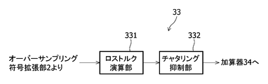
- the motor loss torque compensation unit 33 includes a loss torque calculation unit 331 and a chattering suppression unit 332.
- the loss torque calculation unit 331 obtains the motor loss torque compensation torque based on the code-extended motor speed signal input from the oversampling code extension unit 2.
- the motor loss torque compensation torque is a torque that compensates in advance for torque in a range that does not become torque even if a current is passed through the electric motor by magnetic attraction or the like.
- the loss torque calculation unit 331 outputs a torque signal corresponding to the obtained motor loss torque compensation torque to the chattering suppression unit 332.
- the chattering suppression unit 332 suppresses the chattering generated in the torque signal input from the loss torque calculation unit 331 by a low-pass filter or the like and outputs the chattering to the adder 34.
- the FIR filter 22 and FIR filter 24 of the oversampling code extension unit 2 can adjust the gain characteristic and the phase characteristic by adjusting the weighting coefficient, and the more up-to-date the oversampling signal as the input signal, the more the gain characteristic and the phase characteristic can be adjusted.
- the oversampling signal is weighted and moved and averaged by multiplying it by a large weighting coefficient (h 0 > h 1 > h 2 >...> h N-1 > h N ) to increase the weight.
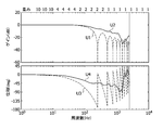
- the phase lag can be reduced by increasing the weighting factor of the latest oversampling signal. As a result, as shown in FIG.
- the FIR filter 22 or the FIR filter 24 creates a notch in the gain U2 of the code-extended steering torque signal and the code-extended motor speed signal obtained by the weighted moving average, which is an output signal.
- the gain U1 of the code-extended steering torque signal and the code-extended motor speed signal obtained by the moving average can be reduced, and the code-extended steering torque signal and the code-extended motor speed signal obtained by the weighted moving average can be reduced.
- the delay of the phase U4 of the above can be reduced as compared with the phase U3 of the code-extended steering torque signal and the code-extended motor speed signal obtained by the moving average.
- the FIR filter since the FIR filter has a higher filter order than the IIR filter having the same cutoff frequency, it has an advantage that the degree of freedom of adjustment of the gain characteristic and the phase characteristic is large.
- the assist control band of the electric power steering device is set to be up to 80 Hz. This reduces the phase lag up to 100 Hz and configures an FIR filter with sufficient attenuation near the Nyquist frequency of -3 to -10 dB, which is a trade-off between controllability and noise sensitivity of the electric power steering device. Will be able to dissolve the relationship.
- the Nyquist frequency is half the frequency of oversampling.
- the oversampling code extension unit 2 oversamples the steering torque signal or the motor speed signal at a cycle faster than the control cycle when controlling the assist torque, and by weighted moving averaging, the AD converter or the like
- the sensor noise of the above can be reduced, and the resolution of the digital signal used in the EPS control unit 3 can be increased from, for example, about 12 bits to about 15 bits.
- This cutoff frequency is usually about 10 times higher than the control band of the electric power steering device.
- the order of the filter in the FIR filter is determined. Since the resolution of the digital signal input by the moving average effect of the FIR filter can be improved, the order of the filter can be set according to the magnitude of the resolution to be increased, that is, the number of bits to be increased.
- the relationship between the degree X of the filter and the number of bits Y is generally expressed by the following (Equation 1). For example, by setting the order X of the filter to 8, the number of bits Y can be obtained to be 3. That is, if the order X of the filter is set to 8, the resolution of the digital signal used in the EPS control unit 3 can be increased by 3 bits.
- the filter coefficient of the FIR filter is calculated from the cutoff frequency and the order of the filter in the FIR filter described above.
- the window function method is used to calculate the filter coefficient.
- the order of the filters to be used is limited to half (X / 2) or less.
- the order of the filter used for calculating the filter coefficient is 4 or less.
- the filter coefficient calculated by the order of this filter is set to 0.
- the filter coefficient obtained by the above calculation of the filter coefficient does not increase the weighting coefficient for the latest input signal, so there is a problem that the phase delay becomes large. Therefore, in order to increase the weighting coefficient and reduce the phase lag for the latest input signal, the filter coefficient is adjusted while maintaining the state where the sum of the filter coefficients is 1.
- the filter coefficient is adjusted while maintaining the state where the sum of the filter coefficients is 1.
- target values are set for each of the phase characteristic and the gain characteristic, and the weighting coefficient of the FIR filter is adjusted so that the amount of attenuation of the gain characteristic near the Nyquist frequency becomes large.
- the adjustment of the weighting coefficient of this FIR filter may be obtained by an optimization process using the control system CAD.
- the motor loss torque compensating unit 33 compensates for this loss torque by setting the torque that does not become torque even if a current is passed due to the magnetic attraction force of the magnet of the electric motor as the loss torque of the electric motor.
- the motor loss torque compensation unit 33 has a loss torque compensation torque H1 in a range (range in which the drive current is equal to or less than a predetermined value) R1 that does not generate torque even when a drive current is passed through the electric motor. Compensates the torque of the electric motor. As a result, a predetermined motor torque can be obtained in the range R1 of the motor drive current.
- the motor loss torque compensation unit 33 compensates the torque of the electric motor by the loss torque compensation torque H1 in the range R1 equal to or less than the predetermined value of the drive current, and assists the assist torque signal output from the EPS control unit 3.
- the torque from the assist torque L1 before compensation to the assist torque L2 after compensation it is possible to improve the responsiveness to an instruction that generates a minute assist torque in the electric motor.
- the quantization noise reduction compensation unit 4 lowers the gain of the assist torque signal in a frequency band higher than a predetermined frequency of the input assist torque signal.
- the predetermined frequency is preferably a control band for controlling the assist torque, for example, 100 Hz.
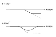
- the quantization noise reduction compensation unit 4 reduces the gain by the IIR filter shown by the solid line in FIG. 6, and the gain in the frequency band higher than the predetermined frequency as compared with the case where the gain is lowered by the low-pass filter shown by the broken line in FIG. Can be lowered.
- the predetermined frequency is, for example, 200 Hz.
- the quantization noise reduction compensation unit 4 performs phase delay compensation for lowering the gain in a frequency band higher than a predetermined frequency of the input assist torque signal. As a result, the quantization error included in the assist torque signal can be reduced.
- the quantization noise reduction compensating unit 4 has a lower phase and poor stability as compared with the case of using the low-pass filter shown by the broken line in FIG. It is possible to suppress the occurrence and delay the phase in a predetermined frequency band.
- the quantization noise reduction compensation unit 4 performs phase delay compensation that lowers the gain in a frequency band higher than a predetermined frequency of the input assist torque signal, thereby resulting in a high frequency due to the differential characteristics in the processing of the EPS control unit 3. It is possible to reduce the quantization error that has moved to the band. That is, the quantization noise reduction compensation unit 4 compensates for the quantization error included in the assist torque signal by reducing the gain in the high frequency band from the predetermined frequency of the assist torque signal.
- FIG. 7 is a diagram showing the results obtained in an experiment conducted to confirm the effect of the present embodiment.
- the control device 1 conventionally has a torque ripple of 0.11 Nm by each process of the oversampling code spreading unit 2, the motor loss torque compensating unit 33, and the quantization noise reduction compensating unit 4. was able to be reduced to 0.03 Nm.
- Vehicles such as automobiles are generally equipped with a power steering device.
- the power steering device generates an auxiliary torque for assisting the steering torque of the steering system generated by the driver operating the steering wheel.
- the auxiliary torque is generated by the auxiliary torque mechanism, and the burden on the driver's operation can be reduced.
- the auxiliary torque mechanism includes a steering torque sensor, an ECU, an electric motor, a speed reduction mechanism, and the like.
- the steering torque sensor detects the steering torque in the steering system.
- the ECU generates a drive signal based on the detection signal of the steering torque sensor.
- the electric motor generates an auxiliary torque according to the steering torque based on the drive signal, and transmits the auxiliary torque to the steering system via the reduction mechanism.
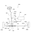
- FIG. 8 is a diagram schematically showing the configuration of the electric power steering device 2000 according to the present embodiment.
- the electric power steering device 2000 includes a steering system 520 and an auxiliary torque mechanism 540.
- the steering system 520 is, for example, a steering wheel 521, a steering shaft 522 (also referred to as a "steering column"), a universal shaft joint 523A, 523B, and a rotating shaft 524 (also referred to as a "pinion shaft” or “input shaft”). ) Is provided.
- the steering system 520 includes, for example, a rack and pinion mechanism 525, a rack shaft 526, left and right ball joints 552A and 552B, tie rods 527A and 527B, knuckles 528A and 528B, and left and right steering wheels (for example, left and right front wheels) 529A. It is equipped with 529B.
- the steering wheel 521 is connected to the rotating shaft 524 via the steering shaft 522 and the universal shaft joints 523A and 523B.
- a rack shaft 526 is connected to the rotating shaft 524 via a rack and pinion mechanism 525.
- the rack and pinion mechanism 525 has a pinion 531 provided on the rotating shaft 524 and a rack 532 provided on the rack shaft 526.
- the right steering wheel 529A is connected to the right end of the rack shaft 526 via a ball joint 552A, a tie rod 527A, and a knuckle 528A in this order.
- the left steering wheel 529B is connected to the left end of the rack shaft 526 via a ball joint 552B, a tie rod 527B and a knuckle 528B in this order.
- the right side and the left side correspond to the right side and the left side as seen from the driver sitting in the seat, respectively.
- steering torque is generated when the driver operates the steering handle 521, and is transmitted to the left and right steering wheels 529A and 259B via the rack and pinion mechanism 525.
- the driver can operate the left and right steering wheels 529A and 529B.
- the auxiliary torque mechanism 540 includes, for example, a steering torque sensor 541, an ECU 542, an electric motor 543, a speed reduction mechanism 544, and a power supply device 545.
- the auxiliary torque mechanism 540 applies auxiliary torque to the steering system 520 from the steering wheel 521 to the left and right steering wheels 529A and 259B.
- the auxiliary torque is sometimes referred to as "additional torque".
- the ECU 542 for example, a control circuit is used.
- the control device 1 of FIG. 1 is included in the ECU 542 as, for example, a microcontroller.
- the power supply device 545 for example, an inverter is used.
- the ECU 542, the electric motor 543, and the power supply device 545 may form a unit generally referred to as a "mechanical-electric integrated motor".
- the mechanism composed of the elements excluding the ECU 542, the electric motor 543, and the power supply device 545 corresponds to an example of the power steering mechanism driven by the electric motor 543.
- the steering torque sensor 541 detects the steering torque of the steering system 520 applied by the steering wheel 521.
- the ECU 542 generates a drive signal for driving the electric motor 543 based on a detection signal (hereinafter, referred to as “torque signal”) from the steering torque sensor 541.
- the electric motor 543 generates an auxiliary torque according to the steering torque based on the drive signal.
- the auxiliary torque is transmitted to the rotating shaft 524 of the steering system 520 via the reduction mechanism 544.
- the reduction mechanism 544 is, for example, a worm gear mechanism. Auxiliary torque is further transmitted from the rotating shaft 524 to the rack and pinion mechanism 525.
- the power steering device 2000 is classified into a pinion assist type, a rack assist type, a column assist type, and the like, depending on where the auxiliary torque is applied to the steering system 520.
- FIG. 8 shows a pinion assist type power steering device 2000.
- the power steering device 2000 is also applied to a rack assist type, a column assist type, and the like.
- a torque signal but also a vehicle speed signal can be input to the ECU 542.
- the microcontroller of the ECU 542 can PWM control the electric motor 543 based on a torque signal, a vehicle speed signal, or the like.
- the ECU 542 sets the target current value at least based on the torque signal. It is preferable that the ECU 542 sets the target current value in consideration of the vehicle speed signal detected by the vehicle speed sensor and further in consideration of the rotation signal of the rotor detected by the angle sensor.
- the ECU 542 can control the drive signal of the electric motor 543, that is, the drive current so that the actual current value detected by the current sensor matches the target current value.
- the left and right steering wheels 529A and 529B can be operated by the rack shaft 526 using the combined torque obtained by adding the auxiliary torque of the electric motor 543 to the steering torque of the driver.
- the power steering device is mentioned as an example of the usage method in the control device of the present invention, but the usage method of the control device of the present invention is not limited to the above, and can be widely used in pumps, compressors and the like.
- the steering torque signal corresponding to the steering torque is oversampled, and the steering torque oversampling signal obtained by the oversampling is weighted by the moving averaging process.
- Base assist control that obtains the base assist torque based on the oversampling code expansion unit 2 that obtains the steering torque after code expansion and the steering torque after code expansion, and obtains the base assist torque signal that decreases the base assist torque as the vehicle speed increases.
- the unit 31 and the stabilization compensation unit 32 that stabilizes the base assist torque signal to obtain an assist torque signal corresponding to the assist torque of the electric power steering device, and reduces the gain in the high frequency band from the predetermined frequency of the assist torque signal.
- Control device 2 Oversampling code diffusion unit 3 EPS control unit 4 Quantization noise reduction compensation unit 5 Current control unit 21 Oversampling unit 22 FIR filter 23 Oversampling unit 24 FIR filter 31 Base assist control unit 32 Stabilization compensation unit 33 Motor Loss torque compensation unit 34 Adder 331 Loss torque calculation unit 332 Chattering suppression unit
Landscapes
- Engineering & Computer Science (AREA)
- Chemical & Material Sciences (AREA)
- Combustion & Propulsion (AREA)
- Transportation (AREA)
- Mechanical Engineering (AREA)
- Power Engineering (AREA)
- Steering Control In Accordance With Driving Conditions (AREA)
- Power Steering Mechanism (AREA)
Abstract
制御装置は、オーバーサンプリング処理によって得られたオーバーサンプリング信号に対して重み付けする移動平均処理を実行することにより符号拡張後操舵トルクを求め、符号拡張後操舵トルク信号に基づいて、ベースアシストトルクを求めると共に、車速が大きいほどベースアシストトルクを減少させるベースアシストトルク信号を取得し、ベースアシストトルク信号に対して安定化処理を実行して電動パワーステアリング装置のアシストトルクに応じたアシストトルク信号を得ると共に、アシストトルク信号の所定周波数よりも高周波帯域のゲインを減少させる。
Description
本発明は、電動パワーステアリング装置の駆動を制御する制御装置、この制御装置によって制御される駆動装置、この駆動装置を備えた電動パワーステアリング装置及び制御方法に関する。
モータを駆動源とする電動パワーステアリング装置(EPS)では、電気的又は機械的な要因によりトルクリップル(脈動)が発生する。このようなトルクリップルが発生した場合には、異音となり、または車両の操舵フィーリングを悪化させる。従って、このようなトルクリップルを低減することが求められている。
従来、トルクリップルが少ないとされている電動パワーステアリング装置のモータでは、約0.2Nmのトルクリップルが発生し、近年ではトルクリップルを0.01Nmオーダーまで抑制するような更に高い水準が求められている。上記のトルクリップルを低減する方法としては、モータの構造を改善する方法、又は制御技術を改善する方法がある。
このような状況において、特許文献1は、トルクリップルを低減するために制御技術を改善して電流フィードバック制御を行う電動パワーステアリング装置を開示している。特許文献1の電動パワーステアリング装置は、実電流値に基づき生成された制御信号に含まれる特定の周波数成分を除去するノッチフィルタによって、トルクリップルを低減する。
しかしながら、特許文献1の技術では、トルクリップルの抑制に対する近年の高い要求水準を満たすことができない場合が有り得る。
本発明の目的は、トルクリップルを低減して、運転者にとって快適な運転を実現することができる制御装置、駆動装置、電動パワーステアリング装置及び制御方法を提供することである。
本発明に係る制御装置は、電動パワーステアリング装置を制御する制御装置であって、操舵トルクに応じた操舵トルク信号に対してオーバーサンプリング処理を行うと共に、前記オーバーサンプリング処理によって得られた操舵トルクオーバーサンプリング信号に対して重み付けする移動平均処理により符号拡張後操舵トルクを求めるオーバーサンプリング符号拡張部と、前記符号化拡張後操舵トルクに基づいてベースアシストトルクを求めるベースアシスト制御部と、を有する。
本発明に係る駆動装置は、上記の制御装置と、前記制御装置によって駆動される電動モータと、を有する。
本発明に係る電動パワーステアリング装置は、上記の制御装置と、前記制御装置によって駆動される電動モータと、前記電動モータによって駆動される電動パワーステアリング機構と、を有する。
本発明に係る制御方法は、電動パワーステアリング装置を制御する制御方法であって、操舵トルクに応じた操舵トルク信号に対してオーバーサンプリング処理を行うステップと、前記オーバーサンプリング処理によって得られた操舵トルクオーバーサンプリング信号に対して重み付けする移動平均処理により符号拡張後操舵トルクを求めるステップと、前記符号化拡張後操舵トルクに基づいてベースアシストトルクを求めるステップと、を有する。
本発明によれば、トルクリップルを低減して、運転者にとって快適な運転を実現することができる。
以下、図面を参照しながら、本発明の実施形態に係る制御装置について説明する。なお、本発明の範囲は、以下の実施の形態に限定されず、本発明の技術的思想の範囲内で任意に変更可能である。また、以下の図面においては、各構成をわかりやすくするために、各構造における縮尺および数等を、実際の構造における縮尺および数等と異ならせる場合がある。
<制御装置の構成>
本発明の実施形態に係る制御装置1の構成について、図1を参照しながら、以下に詳細に説明する。
本発明の実施形態に係る制御装置1の構成について、図1を参照しながら、以下に詳細に説明する。
制御装置1は、後述の電動パワーステアリング機構の駆動を制御する。制御装置1は、オーバーサンプリング符号拡張部2と、EPS制御部3と、量子化雑音低減補償部4と、電流制御部5と、を有している。EPSはElectric Power Steeringの略である。
オーバーサンプリング符号拡張部2は、入力される操舵トルクに応じた操舵トルク信号及びモータ速度に応じたモータ速度信号の各々に対して、オーバーサンプリング符号拡張処理を実行して、符号拡張後操舵トルク信号及び符号拡張後モータ速度信号を得る。オーバーサンプリング符号拡張部2は、得られた符号拡張後操舵トルク信号をEPS制御部3のベースアシスト制御部31に出力すると共に、得られた符号拡張後モータ速度信号をEPS制御部3のモータロストルク補償部33に出力する。なお、オーバーサンプリング符号拡張部2の構成の詳細については図2を用いて後述する。
EPS制御部3は、入力される車速に応じた車速信号と、オーバーサンプリング符号拡張部2から入力される符号拡張後操舵トルク信号及び符号拡張後モータ速度信号と、に基づいて、電動パワーステアリング装置のアシストトルクを求めると共に、求めたアシストトルクを補償する制御を行う。EPS制御部3は、ベースアシスト制御部31と、安定化補償部32と、モータロストルク補償部33と、加算器34と、を備えている。
ベースアシスト制御部31は、入力される車速信号と、オーバーサンプリング符号拡張部2から入力される符号拡張後操舵トルク信号と、に基づいてベースアシストトルクを求める。ベースアシスト制御部31は、例えば車速と操舵トルクとベースアシストトルクとを対応付けたテーブルを予め記憶しており、このテーブルを参照して、入力される車速信号が示す車速と、オーバーサンプリング符号拡張部2から入力される符号拡張後操舵トルク信号が示す操舵トルクと、に対応付けられているベースアシストトルクを求める。ベースアシスト制御部31は、このようにして求めたベースアシストトルクに応じたベースアシストトルク信号を安定化補償部32に出力する。
安定化補償部32は、ベースアシスト制御部31から入力されるベースアシストトルク信号に対して位相進み補償と位相遅れ補償を複数組み合わせた位相補償を行う。位相補償の周波数特性は、操舵状態や走行車速に応じて動的に変化させる。安定化処理を実行して電動パワーステアリング装置のアシストトルクを求め、求めたアシストトルクに応じたアシストトルク信号を加算器34に出力する。
モータロストルク補償部33は、オーバーサンプリング符号拡張部2から入力される符号拡張後モータ速度信号に基づいて、電動モータのアシストトルクを補償するモータロストルク補償トルクを求める。モータロストルク補償部33は、求めたモータロストルク補償トルクに応じたモータロストルク補償トルク信号を加算器34に出力する。なお、モータロストルク補償部33の構成の詳細については図3を用いて後述する。
加算器34は、安定化補償部32から入力されたアシストトルク信号のアシストトルクと、モータロストルク補償部33から入力されたモータロストルク補償トルク信号のモータロストルク補償トルクと、を加算してアシストトルクを補償するトルク補償部である。加算器34は、補償したアシストトルクに応じたアシストトルク信号を量子化雑音低減補償部4に出力する。
量子化雑音低減補償部4は、加算器34から入力されたアシストトルク信号に含まれる量子化誤差をIIRフィルタ等によって低減し、量子化誤差を低減したアシストトルク信号を電流制御部5に出力する。IIRはInfinite Impulse Responseの略である。
電流制御部5は、量子化雑音低減補償部4から入力されるアシストトルク信号に基づいて、電動モータの駆動電流を算出する。電流制御部5により算出された駆動電流は、図示しない電動モータに出力され、電動モータにより、電動パワーステアリング装置が駆動される。
<オーバーサンプリング符号拡張部の構成>
本発明の実施形態に係る制御装置1のオーバーサンプリング符号拡張部2の構成について、図2を参照しながら、以下に詳細に説明する。
本発明の実施形態に係る制御装置1のオーバーサンプリング符号拡張部2の構成について、図2を参照しながら、以下に詳細に説明する。
オーバーサンプリング符号拡張部2は、オーバーサンプリング部21と、FIRフィルタ22と、オーバーサンプリング部23と、FIRフィルタ24と、を備えている。
オーバーサンプリング部21は、入力されるアナログ信号又はデジタル信号である操舵トルク信号をオーバーサンプリングしてデジタル信号である操舵トルクオーバーサンプリング信号を生成し、生成した操舵トルクオーバーサンプリング信号をFIRフィルタ22に出力する。オーバーサンプリング部21は、アシストトルクを制御する際の制御周期よりも速い周期によって操舵トルク信号をオーバーサンプリングする。例えば、オーバーサンプリングの周期は、アシストトルクを制御する際の制御周期が1msecである場合に、200μsecである。
FIRフィルタ22は、オーバーサンプリング部21から入力された操舵トルクオーバーサンプリング信号に対して重み付けする移動平均処理(加重移動平均処理)を実行することにより、操舵トルクオーバーサンプリング信号のゲイン及び位相を制御して符号拡張後操舵トルク信号を得る。FIRフィルタ22は、得られた符号拡張後操舵トルク信号をベースアシスト制御部31に出力する。
オーバーサンプリング部23は、入力されるモータ速度信号をオーバーサンプリングしてモータ速度オーバーサンプリング信号を生成し、生成したモータ速度オーバーサンプリング信号をFIRフィルタ24に出力する。オーバーサンプリング部23は、アシストトルクを制御する際の制御周期よりも速い周期によってモータ速度信号をオーバーサンプリングする。例えば、オーバーサンプリングの周期は、アシストトルクを制御する際の制御周期が1msecである場合に、200μsecである。
FIRフィルタ24は、オーバーサンプリング部23から入力されたモータ速度オーバーサンプリング信号に対して重み付けする移動平均処理を実行することにより、モータ速度オーバーサンプリング信号のゲイン及び位相を制御して符号拡張後モータ速度信号を得る。FIRフィルタ24は、得られた符号拡張後モータ速度信号をモータロストルク補償部33に出力する。
ここで、FIRフィルタ22及びFIRフィルタ24は、同一構成を有し、乗算器221、レジスタ222、乗算器223、加算器224、レジスタ225、乗算器226、加算器227、レジスタ228、乗算器229、加算器230、レジスタ231、乗算器232、加算器233及び乗算器234を備えている。尚、図2において、FIRフィルタ22、24が有する全てのレジスタ、乗算器及び加算器は図示されていない。例えば、レジスタ225と228の間に記載されている「・・・」は、レジスタ225と228の間に所定数のレジスタがあることを示している。乗算器226と229の間の「・・・」も、乗算器226と229の間に所定数の乗算器があることを示している。加算器227と230の間の「・・・」も、加算器227と230の間に所定数の乗算器があることを示している。
乗算器221は、オーバーサンプリング部21又はオーバーサンプリング23からの入力信号x[n]に対して重み係数h0を乗算して加算器224に出力する。
レジスタ222は、オーバーサンプリング部21又はオーバーサンプリング23からの入力信号x[n]に対して1サンプリング周期の遅延を加えて乗算器223及びレジスタ225に出力する。
乗算器223は、レジスタ222の出力信号に対して重み係数h1を乗算して加算器224に出力する。
加算器224は、乗算器221の出力信号と乗算器223の出力信号とを加算して加算器227に出力する。
レジスタ225は、レジスタ222の出力信号に対して1サンプリング周期の遅延を加えて乗算器226及び図示しない後段のレジスタに出力する。
乗算器226は、レジスタ225の出力信号に対して重み係数h2を乗算して加算器227に出力する。
加算器227は、加算器224の出力信号と乗算器226の出力信号とを加算して図示しない後段の加算器に出力する。
レジスタ228は、前段のレジスタの出力信号に対して1サンプリング周期の遅延を加えて乗算器229及びレジスタ231に出力する。
乗算器229は、レジスタ228の出力信号に対して重み係数hN-1を乗算して加算器230に出力する。
加算器230は、図示しない前段の加算器の出力信号と乗算器229の出力信号とを加算して加算器233に出力する。
レジスタ231は、レジスタ228の出力信号に対して1サンプリング周期の遅延を加えて乗算器232に出力する。
乗算器232は、レジスタ231の出力信号に対して重み係数hNを乗算して加算器233に出力する。
加算器233は、加算器230の出力信号と乗算器232の出力信号とを加算して乗算器234に出力する。
乗算器234は、加算器233の出力信号に対して1/wを乗算して得た出力信号y[n]をベースアシスト制御部31又はモータロストルク補償部33に出力する。wは、重み係数h0からhNまでを合計(加算)した合計値である。
<モータロストルク補償部の構成>
本発明の実施形態に係る制御装置1のモータロストルク補償部33の構成について、図3を参照しながら、以下に詳細に説明する。
本発明の実施形態に係る制御装置1のモータロストルク補償部33の構成について、図3を参照しながら、以下に詳細に説明する。
モータロストルク補償部33は、ロストルク演算部331と、チャタリング抑制部332と、を備えている。
ロストルク演算部331は、オーバーサンプリング符号拡張部2から入力された符号拡張後モータ速度信号に基づいて、モータロストルク補償トルクを求める。ここで、モータロストルク補償トルクは、磁気吸引力等によって、電動モータへ電流を流してもトルクにならない範囲のトルクを予め補償するトルクである。ロストルク演算部331は、求めたモータロストルク補償トルクに応じたトルク信号をチャタリング抑制部332に出力する。
チャタリング抑制部332は、ロストルク演算部331から入力されるトルク信号に生じるチャタリングをローパスフィルタ等によって抑制して加算器34に出力する。
<オーバーサンプリング符号拡張部の動作>
本発明の実施形態に係る制御装置1のオーバーサンプリング符号拡張部2の動作について、図4を参照しながら、以下に詳細に説明する。
本発明の実施形態に係る制御装置1のオーバーサンプリング符号拡張部2の動作について、図4を参照しながら、以下に詳細に説明する。
オーバーサンプリング符号拡張部2のFIRフィルタ22及びFIRフィルタ24は、重み係数を調整することでゲイン特性および位相特性を調整することが可能であり、入力信号であるオーバーサンプリング信号が最新であるほど、大きい重み係数(h0>h1>h2>・・・>hN-1>hN)を乗算して重みを大きくして、オーバーサンプリング信号を加重移動平均する。最新のオーバーサンプリング信号の重み係数を大きくすることで、位相遅れを小さくすることができる。これにより、FIRフィルタ22又はFIRフィルタ24は、図4に示すように、出力信号である加重移動平均によって得られる符号拡張後操舵トルク信号及び符号拡張後モータ速度信号のゲインU2に生じるノッチを、移動平均によって得られる符号拡張後操舵トルク信号及び符号拡張後モータ速度信号のゲインU1に比べて低減することができると共に、加重移動平均によって得られる符号拡張後操舵トルク信号及び符号拡張後モータ速度信号の位相U4の遅れを、移動平均によって得られる符号拡張後操舵トルク信号及び符号拡張後モータ速度信号の位相U3に比べて低減することができる。また、FIRフィルタは同じ遮断周波数を持つIIRフィルタよりもフィルタ次数が大きいため、ゲイン特性および位相特性の調整自由度が大きいという利点を有する。
電動パワーステアリング装置の制御性とノイズ感度の間にはトレードオフの関係が存在する。センサノイズ、アシスト制御内の微分特性により高周波帯域に寄せられた量子化誤差成分等に起因する高周波ノイズを抑制しようとすると、ローパスフィルタの減衰特性を増やす必要がある。しかし、減衰特性を増やすと同時に位相遅れも増加する。位相遅れが増えることで制御の遅れ、すなわち操舵の遅れが生じるため、運転者は操舵感に粘性を感じるという問題が発生する。そこで、本発明では、FIRフィルタの重み係数を工夫することで、電動パワーステアリング装置の制御性とノイズ感度の間のトレードオフの関係を解消した。
例えば、電動パワーステアリング装置のアシスト制御帯域を80Hzまでとなるように設定する。これにより、100Hzまでの位相遅れを少なくし、ナイキスト周波数付近の減衰を-3~-10dBで十分としたFIRフィルタを構成することで、電動パワーステアリング装置の制御性とノイズ感度の間のトレードオフの関係を解消することができるようになる。なお、ナイキスト周波数は、オーバーサンプリングの周波数に対して半分の周波数である。
このように、オーバーサンプリング符号拡張部2は、アシストトルクを制御する際の制御周期よりも速い周期によって操舵トルク信号又はモータ速度信号をオーバーサンプリングすると共に、加重移動平均することにより、AD変換器等のセンサノイズを低減することができ、EPS制御部3において使用するデジタル信号の分解能を、例えば12ビットから15ビット程度に上げることができる。
FIRフィルタにおけるフィルタ係数の設計方法について、以下に詳細に記載する。
まず、FIRフィルタにおける遮断周波数を設定する。この遮断周波数は、通常は電動パワーステアリング装置の制御帯域に対して10倍程度高い周波数である。
続いて、FIRフィルタにおけるフィルタの次数を決定する。フィルタの次数は、FIRフィルタによる移動平均効果により入力されるデジタル信号の分解能改善が行えるため、上げたい分解能の大きさ、すなわち増やしたいビット数に応じて設定することができる。フィルタの次数Xとビット数Yの関係は、一般に下記の(式1)で表される。例えば、フィルタの次数Xを8としておくことで、ビット数Yは3と求められる。すなわち、フィルタの次数Xを8としておけば、EPS制御部3において使用するデジタル信号の分解能を、3ビット上げることができる。

次に、先述した遮断周波数とFIRフィルタにおけるフィルタの次数から、FIRフィルタのフィルタ係数を演算する。フィルタ係数の演算には、例えば窓関数法が用いられる。このとき、フィルタの次数をすべて用いると位相遅れが大きくなりすぎるという問題があるため、使用するフィルタの次数は半分(X/2)以下となるように制限される。例えば、フィルタの次数Xを8とした設計の場合、フィルタ係数の演算に用いられるフィルタの次数は4以下となる。ここで、フィルタの次数を半分以下としたことにより、フィルタ係数の演算に用いられないフィルタの次数が存在する。このフィルタの次数によって演算されるフィルタ係数は0としておく。
上記のフィルタ係数の演算によって求められたフィルタ係数は、最新の入力信号に対する重み係数を大きくしていないため、、位相遅れが大きくなるという問題がある。そこで、最新の入力信号に重み係数を大きくし、位相遅れを小さくするために、フィルタ係数の総和が1である状態を維持したまま、フィルタ係数の調整を行う。最新の入力信号にFIRフィルタの重み係数を大きくすることで、位相遅れは改善する一方、ナイキスト周波数付近のゲイン特性は減衰量が少なくなるという問題がある。ここで、位相特性とゲイン特性にそれぞれ目標値を決め、FIRフィルタの重み係数を調整することで、ナイキスト周波数付近のゲイン特性の減衰量が大きくなるように調整する。
なお、このFIRフィルタの重み係数の調整は、制御系CADを用いた最適化処理によって求めてもよい。
<モータロストルク補償部の動作>
本発明の実施形態に係る制御装置1のモータロストルク補償部33の動作について、図5を参照しながら、以下に詳細に説明する。
本発明の実施形態に係る制御装置1のモータロストルク補償部33の動作について、図5を参照しながら、以下に詳細に説明する。
モータロストルク補償部33は、電動モータのマグネットの磁気吸引力等により、電流を流してもトルクにならないトルクを電動モータのロストルクとし、このロストルクを補償する。
具体的には、モータロストルク補償部33は、図5に示すように、電動モータへ駆動電流を流してもトルクにならない範囲(駆動電流が所定値以下の範囲)R1において、ロストルク補償トルクH1によって電動モータのトルクを補償する。これにより、モータ駆動電流の範囲R1において、所定のモータトルクを得ることができる。
このように、モータロストルク補償部33は、駆動電流の所定値以下の範囲R1において、ロストルク補償トルクH1によって電動モータのトルクを補償して、EPS制御部3から出力されるアシストトルク信号のアシストトルクを、補償前のアシストトルクL1から補償後のアシストトルクL2とすることにより、電動モータにおける微小なアシストトルクを生じる指示に対する応答性を改善することができる。
<量子化雑音低減補償部の動作>
本発明の実施形態に係る制御装置1の量子化雑音低減補償部4の動作について、図6を参照しながら、以下に詳細に説明する。
本発明の実施形態に係る制御装置1の量子化雑音低減補償部4の動作について、図6を参照しながら、以下に詳細に説明する。
量子化雑音低減補償部4は、図6に示すように、入力されるアシストトルク信号の所定周波数よりも高周波数帯において、アシストトルク信号のゲインを下げる。ここで、所定周波数は、アシストトルクを制御する際の制御帯域であることが好ましく、例えば100Hzである。量子化雑音低減補償部4は、図6において実線で示すIIRフィルタによってゲインを下げることにより、図6において破線で示すローパスフィルタによってゲインを下げる場合に比べて、所定周波数よりも高周波数帯域におけるゲインを下げることができる。ここで、所定周波数は、例えば200Hzである。
また、量子化雑音低減補償部4は、図6に示すように、入力されるアシストトルク信号の所定周波数より高周波数帯域において、ゲインを下げる位相遅れ補償を行う。これにより、アシストトルク信号に含まれる量子化誤差を低減することができる。量子化雑音低減補償部4は、図6において実線で示すIIRフィルタによって位相遅れ補償を行うことにより、図6において破線で示すローパスフィルタを用いる場合に比べて、位相が下がり過ぎて安定性が悪くなることを抑制することができると共に、所定の周波数帯域において位相を遅らせることができる。
このように、量子化雑音低減補償部4は、入力されるアシストトルク信号の所定周波数より高周波数帯域において、ゲインを下げる位相遅れ補償を行うことにより、EPS制御部3の処理における微分特性により高周波帯域に移動した量子化誤差を低減することができる。すなわち、量子化雑音低減補償部4は、アシストトルク信号の所定周波数よりも高周波帯域のゲインを減少させることにより、アシストトルク信号に含まれる量子化誤差を補償する。
<実施形態の効果>
図7は本実施形態の効果を確認するために行った実験で得た結果を示す図である。制御装置1は、上記のオーバーサンプリング符号拡散部2、モータロストルク補償部33及び量子化雑音低減補償部4における各処理により、図7に示すように、従来において0.11Nmであったトルクリップルを0.03Nmまで低減することができた。
図7は本実施形態の効果を確認するために行った実験で得た結果を示す図である。制御装置1は、上記のオーバーサンプリング符号拡散部2、モータロストルク補償部33及び量子化雑音低減補償部4における各処理により、図7に示すように、従来において0.11Nmであったトルクリップルを0.03Nmまで低減することができた。
<パワーステアリング装置の実施形態>
自動車等の車両は一般的に、パワーステアリング装置を備える。パワーステアリング装置は、運転者がステアリングホイールを操作することによって発生するステアリング系の操舵トルクを補助するための補助トルクを生成する。補助トルクは、補助トルク機構によって生成され、運転者の操作の負担を軽減することができる。例えば、補助トルク機構は、操舵トルクセンサ、ECU、電動モータおよび減速機構などから構成される。操舵トルクセンサは、ステアリング系における操舵トルクを検出する。ECUは、操舵トルクセンサの検出信号に基づいて駆動信号を生成する。電動モータは、駆動信号に基づいて操舵トルクに応じた補助トルクを生成し、減速機構を介してステアリング系に補助トルクを伝達する。
自動車等の車両は一般的に、パワーステアリング装置を備える。パワーステアリング装置は、運転者がステアリングホイールを操作することによって発生するステアリング系の操舵トルクを補助するための補助トルクを生成する。補助トルクは、補助トルク機構によって生成され、運転者の操作の負担を軽減することができる。例えば、補助トルク機構は、操舵トルクセンサ、ECU、電動モータおよび減速機構などから構成される。操舵トルクセンサは、ステアリング系における操舵トルクを検出する。ECUは、操舵トルクセンサの検出信号に基づいて駆動信号を生成する。電動モータは、駆動信号に基づいて操舵トルクに応じた補助トルクを生成し、減速機構を介してステアリング系に補助トルクを伝達する。
上記実施形態の制御装置1は、パワーステアリング装置に好適に利用される。図8は、本実施形態による電動パワーステアリング装置2000の構成を模式的に示す図である。
電動パワーステアリング装置2000は、ステアリング系520および補助トルク機構540を備える。
ステアリング系520は、例えば、ステアリングホイール521、ステアリングシャフト522(「ステアリングコラム」とも称される。)、自在軸継手523A、523B、および回転軸524(「ピニオン軸」または「入力軸」とも称される。)を備える。
また、ステアリング系520は、例えば、ラックアンドピニオン機構525、ラック軸526、左右のボールジョイント552A、552B、タイロッド527A、527B、ナックル528A、528B、および左右の操舵車輪(例えば左右の前輪)529A、529Bを備える。
ステアリングホイール521は、ステアリングシャフト522と自在軸継手523A、523Bとを介して回転軸524に連結される。回転軸524にはラックアンドピニオン機構525を介してラック軸526が連結される。ラックアンドピニオン機構525は、回転軸524に設けられたピニオン531と、ラック軸526に設けられたラック532とを有する。ラック軸526の右端には、ボールジョイント552A、タイロッド527Aおよびナックル528Aをこの順番で介して右の操舵車輪529Aが連結される。右側と同様に、ラック軸526の左端には、ボールジョイント552B、タイロッド527Bおよびナックル528Bをこの順番で介して左の操舵車輪529Bが連結される。ここで、右側および左側は、座席に座った運転者から見た右側および左側にそれぞれ一致する。
ステアリング系520によれば、運転者がステアリングハンドル521を操作することによって操舵トルクが発生し、ラックアンドピニオン機構525を介して左右の操舵車輪529A、529Bに伝わる。これにより、運転者は左右の操舵車輪529A、529Bを操作することができる。
補助トルク機構540は、例えば、操舵トルクセンサ541、ECU542、電動モータ543、減速機構544および電力供給装置545を備える。補助トルク機構540は、ステアリングホイール521から左右の操舵車輪529A、529Bに至るステアリング系520に補助トルクを与える。なお、補助トルクは「付加トルク」と称されることがある。
ECU542としては、例えば制御回路が用いられる。図1の制御装置1は、例えば、マイクロコントローラとして、ECU542に含まれる。また、電力供給装置545としては、例えばインバータが用いられる。ECU542、電動モータ543および電力供給装置545は、一般的に「機電一体型モータ」と称されるユニットを構成してもよい。
図8に示された各要素のうち、ECU542、電動モータ543および電力供給装置545を除いた要素で構成された機構は、電動モータ543によって駆動されるパワーステアリング機構の一例に相当する。
操舵トルクセンサ541は、ステアリングホイール521によって付与されたステアリング系520の操舵トルクを検出する。ECU542は、操舵トルクセンサ541からの検出信号(以下、「トルク信号」と表記する。)に基づいて電動モータ543を駆動するための駆動信号を生成する。電動モータ543は、操舵トルクに応じた補助トルクを駆動信号に基づいて発生する。補助トルクは、減速機構544を介してステアリング系520の回転軸524に伝達される。減速機構544は、例えばウォームギヤ機構である。補助トルクはさらに、回転軸524からラックアンドピニオン機構525に伝達される。
パワーステアリング装置2000は、補助トルクがステアリング系520に付与される箇所によって、ピニオンアシスト型、ラックアシスト型、およびコラムアシスト型等に分類される。図8には、ピニオンアシスト型のパワーステアリング装置2000が示される。ただし、パワーステアリング装置2000は、ラックアシスト型、コラムアシスト型等にも適用される。
ECU542には、トルク信号だけでなく、例えば車速信号も入力され得る。ECU542のマイクロコントローラは、トルク信号や車速信号などに基づいて電動モータ543をPWM制御することができる。
ECU542は、少なくともトルク信号に基づいて目標電流値を設定する。ECU542は、車速センサによって検出された車速信号を考慮し、さらに角度センサによって検出されたロータの回転信号を考慮して、目標電流値を設定することが好ましい。ECU542は、電流センサによって検出された実電流値が目標電流値に一致するように、電動モータ543の駆動信号、つまり、駆動電流を制御することができる。
パワーステアリング装置2000によれば、運転者の操舵トルクに電動モータ543の補助トルクを加えた複合トルクを利用してラック軸526によって左右の操舵車輪529A、529Bを操作することができる。
また、上記では、本発明の制御装置における使用方法の一例としてパワーステアリング装置が挙げられるが、本発明の制御装置の使用方法は上記に限定されず、ポンプ、コンプレッサなど広範囲に使用可能である。
このように、本実施形態によれば、操舵トルクに応じた操舵トルク信号に対してオーバーサンプリング処理を行うと共に、オーバーサンプリング処理によって得られた操舵トルクオーバーサンプリング信号に対して重み付けする移動平均処理により符号拡張後操舵トルクを求めるオーバーサンプリング符号拡張部2と、符号化拡張後操舵トルクに基づいてベースアシストトルクを求めると共に、車速が大きいほどベースアシストトルクを減少させるベースアシストトルク信号を得るベースアシスト制御部31と、ベースアシストトルク信号を安定化処理して電動パワーステアリング装置のアシストトルクに応じたアシストトルク信号を得る安定化補償部32と、アシストトルク信号の所定周波数よりも高周波帯域のゲインを減少させることにより、アシストトルク信号に含まれる量子化誤差を補償する量子化雑音低減補償部4と、を有することにより、トルクリップルを低減して、運転者にとって快適な運転を実現することができる。
上述した実施形態は、すべての点で例示であって制限的なものではないと考えられるべきである。本発明の範囲は上記した実施の形態ではなくて請求の範囲によって示され、請求の範囲と均等の意味及び範囲内でのすべての変更が含まれることが意図される。
1 制御装置
2 オーバーサンプリング符号拡散部
3 EPS制御部
4 量子化雑音低減補償部
5 電流制御部
21 オーバーサンプリング部
22 FIRフィルタ
23 オーバーサンプリング部
24 FIRフィルタ
31 ベースアシスト制御部
32 安定化補償部
33 モータロストルク補償部
34 加算器
331 ロストルク演算部
332 チャタリング抑制部
2 オーバーサンプリング符号拡散部
3 EPS制御部
4 量子化雑音低減補償部
5 電流制御部
21 オーバーサンプリング部
22 FIRフィルタ
23 オーバーサンプリング部
24 FIRフィルタ
31 ベースアシスト制御部
32 安定化補償部
33 モータロストルク補償部
34 加算器
331 ロストルク演算部
332 チャタリング抑制部
Claims (16)
- 電動パワーステアリング装置を制御する制御装置であって、
操舵トルクに応じた操舵トルク信号に対してオーバーサンプリング処理を行うと共に、
前記オーバーサンプリング処理によって得られた操舵トルクオーバーサンプリング信号に対して重み付けする移動平均処理により符号拡張後操舵トルクを求めるオーバーサンプリング符号拡張部と、
前記符号化拡張後操舵トルクに基づいてベースアシストトルクを求めるベースアシスト制御部と、
を有することを特徴とする制御装置。 - 前記ベースアシスト制御部は、
車速が大きいほど前記ベースアシストトルクを減少させるベースアシストトルク信号を得ることを特徴とする請求項1記載の制御装置。 - 前記ベースアシストトルク信号に対して位相進み補償と位相遅れ補償を複数組み合わせた位相補償を行うことで、前記電動パワーステアリング装置のアシストトルクに応じたアシストトルク信号を得る安定化補償部を有することを特徴とする、請求項1または2に記載の制御装置。
- 前記アシストトルク信号の所定周波数よりも高周波帯域のゲインを減少させることにより、前記アシストトルク信号に含まれる量子化誤差を補償する量子化雑音低減補償部を有することを特徴とする、請求項1から請求項3の何れかに記載の制御装置。
- 前記電動パワーステアリング装置の電動モータを駆動させるための駆動電流が所定値以下の際に損失する前記アシストトルクを補償するモータロストルク補償トルクを求めるモータロストルク補償部と、
前記安定化補償部により得られる前記アシストトルクを前記モータロストルク補償トルクによって補償するトルク補償部と、
を有し、
前記オーバーサンプリング符号拡張部は、
前記電動モータの速度に応じたモータ速度信号に対して前記オーバーサンプリング処理を行うと共に、前記オーバーサンプリング処理によって得られたモータ速度オーバーサンプリング信号に対して重み付けをする移動平均処理により符号拡張後モータ速度信号を取得し、
前記モータロストルク補償部は、
前記符号拡張後モータ速度信号に基づいて、前記モータロストルク補償トルクを求め、
前記量子化雑音低減補償部は、
前記トルク補償部によって補償された前記アシストトルクに応じた前記アシストトルク信号に含まれる前記量子化誤差を補償する、
ことを特徴とする請求項1から請求項4の何れかに記載の制御装置 - 前記モータロストルク補償部は、
前記モータロストルク補償トルクを求める際に生じるチャタリングを抑制する、
ことを特徴とする請求項5記載の制御装置。 - 前記オーバーサンプリング処理部は、
前記アシストトルクを制御する際の制御周期よりも速い周期によって前記オーバーサンプリング処理を行う、
ことを特徴とする請求項1から請求項6の何れかに記載の制御装置。 - 前記オーバーサンプリング処理部は、
FIRフィルタによって前記移動平均処理を実行する、
ことを特徴とする請求項1から請求項7の何れかに記載の制御装置。 - 前記FIRフィルタは、ナイキスト周波数付近のゲイン特性を-3~-10dBの減衰量とすることを特徴とする、請求項8記載の制御装置。
- 前記所定周波数は、
前記アシストトルクを制御する際の制御帯域である、
ことを特徴とする請求項1から請求項9の何れかに記載の制御装置。 - 前記量子化雑音低減補償部は、
IIRフィルタによって前記量子化誤差を補償する、
ことを特徴とする請求項1から請求項10の何れかに記載の制御装置。 - 請求項1から請求項11の何れかに記載の制御装置と、
前記制御装置によって駆動される電動モータと、
を有することを特徴とする駆動装置。 - 請求項1から請求項11の何れかに記載の制御装置と、
前記制御装置によって駆動される電動モータと、
前記電動モータによって駆動される電動パワーステアリング機構と、
を有することを特徴とする電動パワーステアリング装置。 - 電動パワーステアリング装置を制御する制御方法であって、
操舵トルクに応じた操舵トルク信号に対してオーバーサンプリング処理を行うステップと、
前記オーバーサンプリング処理によって得られた操舵トルクオーバーサンプリング信号に対して重み付けする移動平均処理により符号拡張後操舵トルクを求めるステップと、
前記符号化拡張後操舵トルクに基づいてベースアシストトルクを求めるステップと、
を有することを特徴とする制御方法。 - 前記車速が大きいほど前記ベースアシストトルクを減少させるベースアシストトルク信号を得るステップと、
前記ベースアシストトルク信号を安定化処理して前記電動パワーステアリング装置のアシストトルクに応じたアシストトルク信号を得るステップと、
前記アシストトルク信号の所定周波数よりも高周波数帯域のゲインを減少させることにより、前記アシストトルク信号に含まれる量子化誤差を補償するステップと、
を有することを特徴とする請求項14記載の制御方法。 - 前記電動パワーステアリング装置の電動モータの速度に応じたモータ速度信号に対して前記オーバーサンプリング処理を行うステップと、
前記オーバーサンプリング処理によって得られたモータ速度オーバーサンプリング信号に対して重み付けをする移動平均処理により符号拡張後モータ速度信号を得るステップ、
前記符号拡張後モータ速度信号に基づいて、前記電動モータを駆動させるための駆動電流が所定値以下の際に損失する前記アシストトルクを補償するモータロストルク補償トルクを求めるステップと、
前記アシストトルクを前記モータロストルク補償トルクによって補償するステップと、
を有し、
補償された前記アシストトルクに応じた前記アシストトルク信号に含まれる前記量子化誤差を補償する、
ことを特徴とする請求項15記載の制御方法。
Priority Applications (4)
| Application Number | Priority Date | Filing Date | Title |
|---|---|---|---|
| JP2021539253A JPWO2021029331A1 (ja) | 2019-08-09 | 2020-08-06 | |
| DE112020003780.0T DE112020003780B4 (de) | 2019-08-09 | 2020-08-06 | Steuervorrichtung, antriebsvorrichtung, elektrische servolenkungsvorrichtung und steuerverfahren |
| US17/632,379 US11702131B2 (en) | 2019-08-09 | 2020-08-06 | Control device, drive device, electric power steering device, and control method |
| CN202080055975.8A CN114206705B (zh) | 2019-08-09 | 2020-08-06 | 控制装置、驱动装置、电动助力转向装置以及控制方法 |
Applications Claiming Priority (2)
| Application Number | Priority Date | Filing Date | Title |
|---|---|---|---|
| JP2019147464 | 2019-08-09 | ||
| JP2019-147464 | 2019-08-09 |
Publications (1)
| Publication Number | Publication Date |
|---|---|
| WO2021029331A1 true WO2021029331A1 (ja) | 2021-02-18 |
Family
ID=74569660
Family Applications (1)
| Application Number | Title | Priority Date | Filing Date |
|---|---|---|---|
| PCT/JP2020/030254 Ceased WO2021029331A1 (ja) | 2019-08-09 | 2020-08-06 | 制御装置、駆動装置、電動パワーステアリング装置及び制御方法 |
Country Status (5)
| Country | Link |
|---|---|
| US (1) | US11702131B2 (ja) |
| JP (1) | JPWO2021029331A1 (ja) |
| CN (1) | CN114206705B (ja) |
| DE (1) | DE112020003780B4 (ja) |
| WO (1) | WO2021029331A1 (ja) |
Cited By (1)
| Publication number | Priority date | Publication date | Assignee | Title |
|---|---|---|---|---|
| US20230192191A1 (en) * | 2021-12-22 | 2023-06-22 | Aptiv Technologies Limited | Evasive Steering Assist Modification Based on Manual Steering Inputs |
Families Citing this family (1)
| Publication number | Priority date | Publication date | Assignee | Title |
|---|---|---|---|---|
| CN116552628B (zh) * | 2023-05-15 | 2025-10-31 | 武汉光庭信息技术股份有限公司 | 一种底盘域eps系统的扭矩补偿控制方法 |
Citations (4)
| Publication number | Priority date | Publication date | Assignee | Title |
|---|---|---|---|---|
| JPH10324262A (ja) * | 1997-05-22 | 1998-12-08 | Kayaba Ind Co Ltd | 電動式パワーステアリングシステム |
| US20070164691A1 (en) * | 2005-09-29 | 2007-07-19 | Agile Systems Inc. | System and method for attenuating noise associated with a back electromotive force signal in a motor |
| US20100211263A1 (en) * | 2009-02-13 | 2010-08-19 | Gm Global Technology Operations, Inc. | Learning controller for the compensation of torque pulsations in a steering assembly |
| JP2019088036A (ja) * | 2017-11-01 | 2019-06-06 | 株式会社デンソー | 電流検出装置、及び回転電機の制御装置 |
Family Cites Families (8)
| Publication number | Priority date | Publication date | Assignee | Title |
|---|---|---|---|---|
| US6107767A (en) | 1998-03-20 | 2000-08-22 | Trw Inc. | Electric assist steering system having an improved motor current controller with notch filter |
| JP4539154B2 (ja) * | 2004-04-21 | 2010-09-08 | 日産自動車株式会社 | 電動パワーステアリング装置 |
| JP4737402B2 (ja) * | 2005-09-21 | 2011-08-03 | 株式会社ジェイテクト | 電動パワーステアリング装置 |
| EP1876423B1 (en) | 2006-07-04 | 2015-10-28 | Toyo Denso Kabushiki Kaisha | Rudder angle sensor |
| EP2955081B1 (en) * | 2013-02-08 | 2017-09-27 | NSK Ltd. | Electric power steering device |
| JP6187042B2 (ja) * | 2013-08-29 | 2017-08-30 | 株式会社ジェイテクト | 電動パワーステアリング装置 |
| WO2016208665A1 (ja) * | 2015-06-26 | 2016-12-29 | 日本精工株式会社 | 電動パワーステアリング機構を用いた運転支援制御装置 |
| JP2019023038A (ja) * | 2017-07-24 | 2019-02-14 | 株式会社ジェイテクト | 操舵制御装置 |
-
2020
- 2020-08-06 JP JP2021539253A patent/JPWO2021029331A1/ja active Pending
- 2020-08-06 US US17/632,379 patent/US11702131B2/en active Active
- 2020-08-06 CN CN202080055975.8A patent/CN114206705B/zh active Active
- 2020-08-06 WO PCT/JP2020/030254 patent/WO2021029331A1/ja not_active Ceased
- 2020-08-06 DE DE112020003780.0T patent/DE112020003780B4/de active Active
Patent Citations (4)
| Publication number | Priority date | Publication date | Assignee | Title |
|---|---|---|---|---|
| JPH10324262A (ja) * | 1997-05-22 | 1998-12-08 | Kayaba Ind Co Ltd | 電動式パワーステアリングシステム |
| US20070164691A1 (en) * | 2005-09-29 | 2007-07-19 | Agile Systems Inc. | System and method for attenuating noise associated with a back electromotive force signal in a motor |
| US20100211263A1 (en) * | 2009-02-13 | 2010-08-19 | Gm Global Technology Operations, Inc. | Learning controller for the compensation of torque pulsations in a steering assembly |
| JP2019088036A (ja) * | 2017-11-01 | 2019-06-06 | 株式会社デンソー | 電流検出装置、及び回転電機の制御装置 |
Cited By (3)
| Publication number | Priority date | Publication date | Assignee | Title |
|---|---|---|---|---|
| US20230192191A1 (en) * | 2021-12-22 | 2023-06-22 | Aptiv Technologies Limited | Evasive Steering Assist Modification Based on Manual Steering Inputs |
| CN116331345A (zh) * | 2021-12-22 | 2023-06-27 | 安波福技术有限公司 | 基于手动转向输入的规避转向辅助修改 |
| US12280824B2 (en) * | 2021-12-22 | 2025-04-22 | Aptiv Technologies AG | Evasive steering assist modification based on manual steering inputs |
Also Published As
| Publication number | Publication date |
|---|---|
| CN114206705A (zh) | 2022-03-18 |
| JPWO2021029331A1 (ja) | 2021-02-18 |
| CN114206705B (zh) | 2024-01-12 |
| US11702131B2 (en) | 2023-07-18 |
| DE112020003780B4 (de) | 2025-01-23 |
| US20220289285A1 (en) | 2022-09-15 |
| DE112020003780T5 (de) | 2022-06-30 |
Similar Documents
| Publication | Publication Date | Title |
|---|---|---|
| JP4286834B2 (ja) | 操舵制御装置 | |
| JP5383818B2 (ja) | 電動パワーステアリング制御装置 | |
| US7849957B2 (en) | Control apparatus for electric power steering | |
| JP3847516B2 (ja) | 電動パワーステアリング制御装置及びその制御方法 | |
| US20140058630A1 (en) | Electric power steering control device | |
| JP6705314B2 (ja) | ステアリング制御装置 | |
| WO2012073760A1 (ja) | 電動パワーステアリング装置 | |
| WO2014021369A1 (ja) | 電動パワーステアリングシステムを制御する装置及びその方法 | |
| JPH0872732A (ja) | 電動パワーステアリング装置 | |
| CN114206706B (zh) | 控制装置、驱动装置、电动助力转向装置以及控制方法 | |
| CN104417601A (zh) | 电动式转向装置的转向感稳定化装置及方法 | |
| CN114206705B (zh) | 控制装置、驱动装置、电动助力转向装置以及控制方法 | |
| CN111629955B (zh) | 动力转向装置的控制装置 | |
| WO2021029330A1 (ja) | 電動パワーステアリング装置、電動パワーステアリング装置に用いられる制御装置、および制御方法 | |
| JP2011121383A (ja) | 電動パワーステアリング制御装置 | |
| CN107949517A (zh) | 电动助力转向装置 | |
| JP2023008890A (ja) | ステアバイワイヤの操舵反力装置 | |
| JP6413633B2 (ja) | 電動パワーステアリング装置 | |
| JP2010069975A (ja) | 電動パワーステアリング装置 | |
| JP6737026B2 (ja) | ステアリング制御装置 | |
| JP5880048B2 (ja) | 電動車両の制御方法及び電動車両の制御装置 | |
| JP2025009738A (ja) | 制御装置、電動パワーステアリング装置、および駆動装置 | |
| JP7768762B2 (ja) | モータの制御装置、モータの制御方法、モータモジュールおよび電動パワーステアリング装置 | |
| JP3103049B2 (ja) | 車両用操舵装置 | |
| KR102372401B1 (ko) | 전동식 동력 조향장치의 조향감 제어 장치 및 방법 |
Legal Events
| Date | Code | Title | Description |
|---|---|---|---|
| 121 | Ep: the epo has been informed by wipo that ep was designated in this application |
Ref document number: 20853063 Country of ref document: EP Kind code of ref document: A1 |
|
| ENP | Entry into the national phase |
Ref document number: 2021539253 Country of ref document: JP Kind code of ref document: A |
|
| 122 | Ep: pct application non-entry in european phase |
Ref document number: 20853063 Country of ref document: EP Kind code of ref document: A1 |