WO2021029209A1 - ヘッド交換式切削工具、切削ヘッド、および工具本体 - Google Patents
ヘッド交換式切削工具、切削ヘッド、および工具本体 Download PDFInfo
- Publication number
- WO2021029209A1 WO2021029209A1 PCT/JP2020/028681 JP2020028681W WO2021029209A1 WO 2021029209 A1 WO2021029209 A1 WO 2021029209A1 JP 2020028681 W JP2020028681 W JP 2020028681W WO 2021029209 A1 WO2021029209 A1 WO 2021029209A1
- Authority
- WO
- WIPO (PCT)
- Prior art keywords
- head
- cutting
- cutting head
- tool
- tool body
- Prior art date
Links
Images


Classifications
-
- B—PERFORMING OPERATIONS; TRANSPORTING
- B23—MACHINE TOOLS; METAL-WORKING NOT OTHERWISE PROVIDED FOR
- B23C—MILLING
- B23C5/00—Milling-cutters
-
- B—PERFORMING OPERATIONS; TRANSPORTING
- B23—MACHINE TOOLS; METAL-WORKING NOT OTHERWISE PROVIDED FOR
- B23C—MILLING
- B23C5/00—Milling-cutters
- B23C5/16—Milling-cutters characterised by physical features other than shape
-
- B—PERFORMING OPERATIONS; TRANSPORTING
- B23—MACHINE TOOLS; METAL-WORKING NOT OTHERWISE PROVIDED FOR
- B23C—MILLING
- B23C5/00—Milling-cutters
- B23C5/02—Milling-cutters characterised by the shape of the cutter
- B23C5/10—Shank-type cutters, i.e. with an integral shaft
-
- B—PERFORMING OPERATIONS; TRANSPORTING
- B23—MACHINE TOOLS; METAL-WORKING NOT OTHERWISE PROVIDED FOR
- B23B—TURNING; BORING
- B23B51/00—Tools for drilling machines
-
- B—PERFORMING OPERATIONS; TRANSPORTING
- B23—MACHINE TOOLS; METAL-WORKING NOT OTHERWISE PROVIDED FOR
- B23B—TURNING; BORING
- B23B2205/00—Fixation of cutting inserts in holders
- B23B2205/04—Fixation screws, bolts or pins of particular form
-
- B—PERFORMING OPERATIONS; TRANSPORTING
- B23—MACHINE TOOLS; METAL-WORKING NOT OTHERWISE PROVIDED FOR
- B23C—MILLING
- B23C2210/00—Details of milling cutters
- B23C2210/02—Connections between the shanks and detachable cutting heads
-
- B—PERFORMING OPERATIONS; TRANSPORTING
- B23—MACHINE TOOLS; METAL-WORKING NOT OTHERWISE PROVIDED FOR
- B23C—MILLING
- B23C2210/00—Details of milling cutters
- B23C2210/03—Cutting heads comprised of different material than the shank irrespective of whether the head is detachable from the shank
-
- B—PERFORMING OPERATIONS; TRANSPORTING
- B23—MACHINE TOOLS; METAL-WORKING NOT OTHERWISE PROVIDED FOR
- B23C—MILLING
- B23C2210/00—Details of milling cutters
- B23C2210/08—Side or top views of the cutting edge
- B23C2210/084—Curved cutting edges
-
- B—PERFORMING OPERATIONS; TRANSPORTING
- B23—MACHINE TOOLS; METAL-WORKING NOT OTHERWISE PROVIDED FOR
- B23C—MILLING
- B23C2210/00—Details of milling cutters
- B23C2210/16—Fixation of inserts or cutting bits in the tool
- B23C2210/165—Fixation bolts
-
- B—PERFORMING OPERATIONS; TRANSPORTING
- B23—MACHINE TOOLS; METAL-WORKING NOT OTHERWISE PROVIDED FOR
- B23C—MILLING
- B23C2240/00—Details of connections of tools or workpieces
- B23C2240/24—Connections using screws
Definitions
- the present invention is a head-replaceable cutting tool in which a cutting head having a cutting edge is detachably attached to the tip of a shaft-shaped tool body that is rotated in the tool rotation direction around the axis, and this head-replaceable cutting tool.
- the present application claims priority based on Japanese Patent Application No. 2019-147893 filed in Japan on August 9, 2019, the contents of which are incorporated herein by reference.
- a mounting screw penetrating a screw insertion hole provided in the shaft center of a replaceable cutting tool is a shaft center of a holder (tool body).
- the replacement cutting tool is detachably and integrally attached to the tip of the holder, while the key that engages the holder and the replacement cutting tool in a relative non-rotatable manner.
- the replacement cutting tool is provided with a rotation stop engaging portion composed of such an engaging protrusion and an engaging recess such as a keyway, and the replacement cutting tool is rotationally driven around the axis together with the holder.
- the head replaceable cutting tool described in Patent Document 1 includes a cylindrical fitting shaft portion integrally provided in a portion of the mounting screw located straddling the replacement blade and the holder, and a replacement blade.
- a cylindrical cutting tool side fitting hole and a holder that are provided in the screw insertion hole of the above and are fitted to the fitting shaft part by a clearance fit to concentrically position the replacement cutting tool and the fitting shaft part.
- a cylindrical holder side fitting that positions the holder and the fitting shaft concentrically by being provided in the opening of the screw hole that opens at the tip of the screw hole and being fitted to the fitting shaft by a clearance fit. It has a joint hole.
- An object of the present invention is to provide a head-replaceable cutting tool, a cutting head, and a tool body capable of obtaining machining accuracy and excellent machining surface roughness.
- the head replaceable cutting tool is attached to the tip of a shaft-shaped tool body that is rotated in the tool rotation direction around the axis.
- the tool body and the cutting head are such that the contact surface of the tip surface of the tool body on the main body side is the cutting head. It is attached by abutting and adhering to the head-side contact surface of the rear end surface, and the rear end surface of the cutting head and the tip surface of the tool body can be inserted into a recess and the recess.
- the convex portion is formed, and the concave portion and the convex portion are formed so as to become wider in the circumferential direction toward the outer peripheral side in the radial direction with respect to the axis line.
- the cutting head is a cutting head that is detachably attached to the tip of a shaft-shaped tool body that is rotated in the tool rotation direction around the axis of such a head replaceable cutting tool.
- the cutting edge is provided, and the rear end surface of the cutting head is formed on the head side contact surface that abuts and adheres to the body side contact surface of the tip surface of the tool body and the tip surface of the tool body.
- a concave portion into which the convex portion is inserted or a convex portion to be inserted into the concave portion formed on the tip surface of the tool body is formed, and the concave portion or the convex portion faces the outer peripheral side in the radial direction with respect to the axis. It is characterized in that it is formed so as to become wider in the circumferential direction according to the above.
- the tool body according to one aspect of the present invention is a shaft-shaped tool body that can be rotated in the tool rotation direction around the axis, to which the cutting head of the above-mentioned replaceable head cutting tool is detachably attached to the tip portion. Then, it is inserted into the front end surface of the tool body, the main body side contact surface that abuts and adheres to the head side contact surface of the rear end surface of the cutting head, and the recess formed in the rear end surface of the cutting head.
- a convex portion or a concave portion into which a convex portion formed on the rear end surface of the cutting head is inserted is formed, and the convex portion or the concave portion becomes wider in the circumferential direction toward the outer peripheral side in the radial direction with respect to the axis line. It is characterized in that it is formed so as to be.
- a recess formed on the rear end surface of the cutting head and the tip surface of the tool body, and a convex portion that can be inserted into the recess are formed. Since it is formed so as to become wider in the circumferential direction toward the outer peripheral side in the radial direction with respect to the above axis, high mounting strength and high mounting strength can be achieved especially on the outer peripheral side of the cutting head on which a large rotational moment acts due to the cutting torque during cutting.
- the cutting head can be mounted while ensuring the mounting rigidity.
- the cutting head can be attached to the tool body by preventing it from rotating, and even if a large cutting load acts on the cutting edge of the cutting head during cutting, the cutting head is prevented from rattling. Therefore, it is possible to obtain high machining accuracy and excellent machined surface roughness.
- the wall surface of the convex portion facing the tool rotation direction and the concave portion of the convex portion It is desirable that the wall surface facing away from the tool rotation direction extends along the radial direction with respect to the axis.
- the tool rotation direction of the convex portion is formed. It is desirable that the wall surface facing the opposite side and the wall surface facing the tool rotation direction of the recess extend along the radial direction with respect to the axis.
- These wall surfaces serve as receiving surfaces that receive a rotational moment due to cutting torque.
- the cutting head is brought into contact with the wall surfaces.
- the concave portion and the convex portion are the tool body and the cutting. It is desirable that the head is formed so as to be wider in the circumferential direction toward the rear end side, and conversely, the convex portion is formed on the rear end surface of the cutting head and the tool body is formed.
- the concave portion is formed on the tip surface of the tool, the concave portion and the convex portion are formed so as to become wider in the circumferential direction toward the tip side of the tool body and the cutting head. Is desirable.
- the cutting head has high mounting strength and rigidity at the portion where the main body side contact surface of the tip surface of the tool body away from the cutting edge and the head side contact surface of the rear end surface of the cutting head are in contact with each other. Can be supported, and rattling of the cutting head can be prevented more reliably. Further, since it is possible to prevent the cutting head and the tool body from being cut out larger than necessary due to the recesses, it is possible to secure even higher rigidity and to perform cutting with higher accuracy.
- the cutting edge is a cutting tap such as the head exchangeable cutting tool described in Patent Document 1 or a cutting edge of a T-slot cutter, which is formed only on a portion facing the outer peripheral side of the cutting head.
- it may be a cutting edge of an end mill including a portion facing the outer peripheral side of the cutting head and a portion facing the tip end side of the cutting head.
- a through hole that opens in the head-side contact surface is formed in the cutting head along the axis, and a screw hole is formed in the tool body along the axis, so that the cutting head has a head.
- the clamp screw provided with the portion and inserted into the through hole is detachably attached to the tool body by being screwed into the screw hole, the concave portion and the convex portion are formed in the through hole.
- the through hole is formed in a circular cross section having a constant inner diameter centered on the axis, and is opened on the tip side of the cutting head so as to communicate with the through hole and open on the tip side of the cutting head.
- a counterbore is formed, and the tip of the tool body has a circular cross section with a constant inner diameter equal to that of the through hole centered on the axis at the opening of the screw hole to the main body side contact surface.
- the mounting hole is formed, and the clamp screw is fitted into the disc-shaped head house accommodated in the counterbore hole and the through hole and the mounting hole extending toward the rear end side of the head.
- the cutting head When the cutting head is detachably attached to the tool body with a clamp screw, A> B when the Vickers hardness of the cutting head is A, the Vickers hardness of the tool body is B, and the Vickers hardness of the clamp screw is C. It is desirable that the relationship is ⁇ C or A ⁇ B> C. As a result, since the clamp screw is always made of a soft material having a Vickers hardness lower than that of the cutting head, elasticity can be given to the clamp screw, and the mounting strength of the cutting head can be improved.
- the cutting head can be attached to the tool body by stopping the rotation, and of course, on the outer peripheral side of the cutting head on which a large rotational moment acts due to the cutting torque during cutting. Since the cutting head can be mounted while ensuring high mounting strength and mounting rigidity, it is possible to prevent the cutting head from rattling even if a large cutting load acts on the cutting edge of the cutting head during cutting. It is possible to obtain high machining accuracy and excellent machined surface roughness.
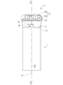
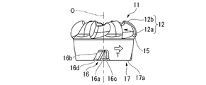
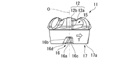
- FIG. 1 It is a perspective view which shows the 1st Embodiment of the head exchange type cutting tool of this invention. It is a top view which looked at the embodiment shown in FIG. 1 from the tip side in the axial direction. It is a side view of the arrow line W direction view in FIG.
- FIG. 3 is a sectional view taken along line YY in FIG. It is an enlarged sectional view of the part A in FIG. It is a side view of the arrow X direction view in FIG. It is a ZZ cross-sectional view in FIG.
- FIG. 7 is an enlarged cross-sectional view of a portion B in FIG. 7. It is an exploded perspective view of the embodiment shown in FIG. It is another exploded perspective view of the embodiment shown in FIG.
- FIG. 12 It is an exploded side view of the embodiment shown in FIG. It is a perspective view which shows the 1st Embodiment of the cutting head of this invention attached to the embodiment shown in FIG. It is a top view which looked at the embodiment shown in FIG. 12 from the tip side in the axial direction. It is a side view of the arrow line W direction view in FIG. It is a side view of the arrow X direction view in FIG. It is a bottom view which looked at the embodiment shown in FIG. 12 from the rear end side in the axial direction. It is a perspective view which shows the 1st Embodiment of the tool body of this invention in the embodiment shown in FIG. It is a top view which looked at the embodiment shown in FIG. 17 from the tip side in the axial direction.
- FIG. 5 is a perspective view of a second embodiment of the cutting head of the present invention attached to the embodiment shown in FIG. 20 as viewed from the rear end side in the axial direction.
- FIG. 22 is a bottom view which looked at the embodiment shown in FIG. 22 from the rear end side in the axial direction.
- FIG. 22 is another exploded perspective view of the embodiment shown in FIG.
- FIGS. 12 to 16 show an embodiment of the cutting head of the present invention attached to this embodiment
- FIG. 19 shows an embodiment of the tool body of the present invention to which the cutting head of this embodiment is attached.
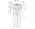
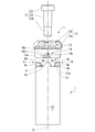
- the tool body 1 is formed of a metal material such as a steel material in a cylindrical shaft shape centered on the axis O as shown in FIGS. 17 to 19. Further, the cutting head 11 is formed in a disk shape centered on the axis O as shown in FIGS. 12 to 16 by using a cemented carbide or the like having a hardness higher than that of the tool body 1.
- the cutting head 11 is attached to the tip of the tool body 1, and the rear end of the tool body 1 is gripped by the main shaft of the machine tool, and the tool rotation direction is around the axis O.
- the work material is cut by the cutting edge 12 formed on the cutting head 11 by being sent out in a direction intersecting the axis O while being rotated by T.
- the tool body 1 has an axis O at the center of the tip surface (upper end surface in FIGS. 1, 3 to 4, 6 to 7, 9 to 11, 17 and 19).
- a mounting hole 2 having a constant inner diameter and a circular cross section, and a rear end side in the O-direction of the axis from the bottom of the mounting hole 2 (FIGS. 1, FIGS. 3 to 4, 6 to 7, 9 to 11, 17).
- a screw hole 3 centered on an axis O having a diameter smaller than that of the mounting hole 2 extending (lower side in FIG. 19) is formed.
- a convex portion 4 is formed on the tip surface of the tool body 1.
- a plurality of (four) convex portions 4 are formed in the tool body 1 of the present embodiment at intervals (equal intervals) in the circumferential direction. These convex portions 4 have the same shape and the same size as each other, and are formed at intervals from the opening of the mounting hole 2 to the outer peripheral side in the radial direction with respect to the axis O, and the side surface 4a of the mounting hole 2 facing the opening side is formed. As shown in FIG.
- the tip surface 4b facing the tip side in the O direction of the axis is inclined toward the inner peripheral side in the radial direction with respect to the axis O toward the rear end side in the O direction of the axis, as shown in FIGS. 7 and 19. It is located on a plane perpendicular to the axis O.
- these convex portions 4 have a wall surface 4c facing the tool rotation direction T extending in a direction along the radial direction with respect to the axis O.
- the wall surface 4d of the convex portion 4 facing the side opposite to the tool rotation direction T is directed to the side opposite to the tool rotation direction T toward the rear end side in the axis O direction as shown in FIG. It is inclined at a constant angle so as to be away from the wall surface 4c facing the tool rotation direction T. Therefore, as a result, the convex portion 4 is formed so as to become wider in the circumferential direction as shown in FIGS.
- the circumferential length of the convex portion 4 on the tip surface 4b and the circumferential length of the bottom surface of the convex portion 4 are the radial outer circumferences with respect to the axis O, respectively. It is formed so that it becomes longer toward the side.
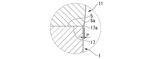
- the portion excluding the convex portion 4 and the opening of the mounting hole 2 has a flat shape perpendicular to the axis O, and the main body side contact of the tip surface in the present embodiment. It is said to be the contact surface 5. Therefore, the outer peripheral edge 5a of the main body-side contact surface 5 is located on the circumference centered on the axis O.
- the side surface 4e of the convex portion 4 facing the outer peripheral side in the radial direction with respect to the axis O is formed in a cylindrical surface shape flush with the outer peripheral surface of the tool body 1.
- the cutting head 11 attached to the tip of the tool body 1 has a central portion thereof on the rear end side (lower side in FIGS. 12, 14 and 15), as shown in FIGS. 4, 7, and 16. As shown, a through hole 13 having a constant inner diameter centered on the axis O along the axis O is formed. The inner diameter of the through hole 13 is substantially equal to the inner diameter of the mounting hole 2 of the tool body 1.
- the cutting head communicates with the through hole 13.
- a constant inner diameter centered on an axis O having a diameter larger than that of the through hole 13 opened on the tip side of 11 or a tapered counterbore 14 whose inner diameter slightly increases toward the tip side of the cutting head 11 is formed.
- the counterbore 14 has a tapered inner peripheral surface, it becomes a draft when the cutting head 11 is formed by powder press molding using a die, and the formability can be improved.
- a plurality of (six) concave groove-shaped tip pockets 15 are formed at the tip of the cutting head 11 at intervals (equal intervals) in the circumferential direction at intervals with the openings of the counterbore holes 14.
- the cutting edge 12 is formed on the edge of the wall surface of these tip pockets 15 facing the tool rotation direction T.
- the cutting edge 12 in the present embodiment is a radius end mill having a substantially 1/4 arc shape from the inner peripheral side of the tip of the cutting head 11 to the outer peripheral side of the rear end. It is a corner blade-shaped cutting edge, and includes a portion of an outer peripheral blade 12a facing the outer peripheral side of the cutting head 11 and a portion of a bottom blade 12b facing the tip end side of the cutting head 11.
- the outer peripheral surface of the rear end portion of the cutting head 11 is formed in a truncated cone shape whose diameter decreases toward the rear end side. Further, on the rear end surface of the cutting head 11, the same number (4) of recesses 16 as the convex portions 4 are opened on the outer peripheral surface of the rear end portion of the cutting head 11 at intervals (equal intervals) in the circumferential direction. Each convex portion 4 of the tool body 1 can be accommodated in these concave portions 16. That is, these recesses 16 are also the same shape and the same size as each other, but are formed slightly larger than the convex portions 4, and the outer circumference in the radial direction from the opening of the through hole 13 on the rear end surface of the cutting head 11 to the axis O. It is formed at intervals on the side.
- the inner wall surface 16a on the opening side of the through hole 13 of these recesses 16 is inclined to the inner peripheral side in the radial direction with respect to the axis O toward the rear end side in the axis O direction, and faces the rear end side in the axis O direction.
- the bottom surface 16b is located on a plane perpendicular to the axis O as shown in FIGS. 14 and 15.
- the wall surface 16c of the recess 16 facing the side opposite to the tool rotation direction T is formed so as to extend along the radial direction with respect to the axis O as shown in FIGS. 14 to 16.
- the wall surface 16d of the recess 16 facing the tool rotation direction T faces the side opposite to the tool rotation direction T as it goes toward the rear end side in the axis O direction, and faces the side opposite to the tool rotation direction T. It is inclined at a constant angle so as to be separated from the wall surface 16c. Therefore, as a result, as shown in FIGS. 12 and 14 to 16, the concave portion 16 also has the concave portion 16 in the circumferential direction toward the outer peripheral side in the radial direction with respect to the axis O and the rear end side in the axial direction O direction, as shown in FIGS. It is formed to be wide.
- the circumferential length of the bottom surface 16b of the recess 16 and the circumferential length of the tip surface of the recess 16 are on the outer peripheral side in the radial direction with respect to the axis O, respectively. It is formed so that it becomes longer as it goes toward it.
- the portion excluding these recesses 16 and the opening of the through hole 13 has a flat shape perpendicular to the axis O, and the head side contact of the rear end surface in the present embodiment. It is said to be surface 17. Therefore, the outer peripheral edge 17a of the head-side contact surface 17 of the rear end surface at the rear end of the truncated cone shape of the cutting head 11 is located on the circumference centered on the axis O.
- the bottom surface 14a of the counterbore 14 facing the tip side in the axis O direction is parallel to the head side contact surface 17 or is attached to the head side contact surface 17 at an angle of 5 ° or less in a cross section along the axis O.
- the cutting head 11 is inclined toward the rear end side toward the inner peripheral side.
- the cutting head 11 formed of such a hard material such as cemented carbide is manufactured according to the basic process of powder metallurgy technology. That is, when the cutting head 11 is made of cemented carbide, first, a granular granulated powder containing tungsten carbide powder and cobalt powder as main components and chromium, tantalum, etc. as subcomponents is used as necessary, and gold is used. Perform powder press molding using a mold.
- the obtained press-molded product can be produced as a cutting head 11 by sintering the obtained press-molded product in a sintering furnace controlled to an appropriate atmosphere and temperature for a predetermined time.
- the basic shape of the cutting head 11 is reflected by the design of the mold. Further, in order to improve the accuracy of the inner diameter of the through hole 13 of the cutting head 11 and the shape of the cutting edge, machining may be performed using a cutting tool or a grinding wheel as necessary.
- Such a cutting head 11 is coaxially attached with respect to the axis O by the main body side contact surface 5 of the tool body 1 coming into contact with and in close contact with the head side contact surface 17.
- the main body side contact surface 5 and the head side contact surface 17 are such that the outer peripheral edge 17a of the head side contact surface 17 is the main body side contact surface 5 as shown in FIG. It protrudes from the outer peripheral edge 5a toward the outer peripheral side in the radial direction with respect to the axis O.
- the radial protrusion amount P of the outer peripheral edge 17a of the head-side contact surface 17 with respect to the outer peripheral edge 5a of the main body-side contact surface 5 with respect to the axis O is 0.05 mm to 0.8 mm. It is said to be within the range.
- the clamp screw 21 as shown in FIGS. 4, 7 and 9 to 11 is used to coaxially attach the cutting head 11 to the tool body 1 with respect to the axis O.
- the clamp screw 21 has a hardness lower than that of the cemented carbide or the like forming the cutting head 11, and is centered on the axis O by a metal material such as a steel material having a hardness equal to or lower than that of the tool body 1. It is provided with a disk-shaped head portion 22, a columnar shaft portion 23 extending toward the rear end side of the head portion 22, and a male screw portion 24 extending further toward the rear end side of the shaft portion 23. ing.
- the head portion 22 has an outer diameter larger than that of the through hole 13 with a size that can be accommodated in the counterbore 14 of the cutting head 11, and the shaft portion 23 has a through hole of the cutting head 11 having substantially equal inner diameters.
- the outer diameter is set so that it can be fitted into the mounting hole 2 of the tool body 1 and 13 and the male screw portion 24 can be screwed into the screw hole 3 of the tool body 1.
- an engaging hole 22a to which a work tool such as a wrench can be engaged is formed on the tip surface of the head 22.
- the outer peripheral surface of the head 22 may have a cylindrical surface shape centered on the axis O, or may have a tapered shape that slightly increases in diameter toward the tip side. By making the head 22 tapered, the head 22 can be easily attached and detached.
- the convex portion 4 of the tool body 1 is inserted into each concave portion 16, and the wall surface 16c facing the side opposite to the tool rotation direction T of the concave portion 16 has the wall surface 4c facing the tool rotation direction T of the convex portion 4.
- the tool body 1 was inserted through the counterbore hole 14 and the through hole 13 in a state where the main body side contact surface 5 of the tool body 1 was in contact with and brought into close contact with the head side contact surface 17.
- the clamp screw 21 is rotated by a work tool engaged with the engagement hole 22a, and the male screw portion 24 is screwed into the screw hole 3 of the mounting hole 2 of the tool body 1, so that the tool body 1 It can be attached and detached to the tip of the.
- the convex portion 4 formed on the tip surface of the tool body 1 and the cutting head 11 into which the convex portion 4 is inserted Since the recess 16 formed on the rear end surface is formed so as to become wider in the circumferential direction toward the outer peripheral side in the radial direction with respect to the axis O, a large rotational moment acts particularly due to the cutting torque during cutting.
- the cutting head 11 can be mounted on the outer peripheral side of the cutting head 11 while ensuring high mounting strength and mounting rigidity.
- the cutting head 11 can be attached to the tool body 1 by stopping the rotation, and even if a large cutting load acts on the cutting edge 12 of the cutting head 11 during cutting, the cutting head 11 rattles. Can be prevented from occurring. Therefore, according to the head replaceable cutting tool, the cutting head 11, and the tool body 1 having the above configuration, it is possible to obtain high machining accuracy and excellent machined surface roughness.
- the concave portion 16 is formed on the rear end surface of the cutting head 11, and the convex portion 4 is formed on the tip surface of the tool body 1, and the wall surface 4c of the convex portion 4 facing the tool rotation direction T.
- the wall surface 16c of the recess 16 facing the side opposite to the tool rotation direction T are formed so as to extend along the radial direction with respect to the axis O, and these wall surfaces 4c and 16c are formed by the cutting head 11 during cutting. It is a receiving surface that receives a rotational moment due to the cutting torque acting on the cutting edge 12.
- the cutting edge 12 is excessive when cutting is performed with the wall surfaces 4c and 16c in contact with each other. Even if a cutting load is applied, it is necessary to avoid a tensile stress that pulls the cutting head 11 radially to the outer peripheral side with respect to the axis O and a compressive stress that compresses the cutting head 11 to the radial inner peripheral side with respect to the axis O. be able to.
- the wall surfaces 4c and 16c extend along the radial direction with respect to the axis O means that the wall surfaces 4c and 16c are located on a plane including the axis O, or after the axis O direction at a constant angle with respect to this plane. It suffices that the wall surfaces 4c and 16c have a portion extending in the radial direction with respect to the axis O in any cross section perpendicular to the axis O, which is slightly inclined toward the tool rotation direction T side toward the end side.
- the concave portion 16 is formed on the rear end surface of the cutting head 11, and the convex portion 4 is formed on the tip surface of the tool body 1.
- the concave portion 16 and the convex portion 4 are the tool body 1. It is formed so as to become wider in the circumferential direction toward the rear end side of the cutting head 11.
- the cutting head 11 has high mounting strength and mounting rigidity. Therefore, according to the present embodiment, it is possible to more reliably prevent the cutting head 11 from rattling, and it is possible to obtain higher machining accuracy and excellent finished surface roughness. Further, since it is possible to prevent the cutting head 11 from being cut out larger than necessary by the recess 16, it is possible to give the cutting head even higher rigidity, which also makes it possible to perform cutting with higher precision. It becomes.
- the cutting edge 12 of the cutting head 11 is an end mill (radius end mill) including a portion of the outer peripheral blade 12a facing the outer peripheral side of the cutting head 11 and a portion of the bottom blade 12b facing the tip end side of the cutting head 11. It is said to be the cutting edge 12. Therefore, for example, the wall surface and the bottom surface of the mold can be cut by such a cutting edge 12.
- the cutting head 11 is formed with a through hole 13 that opens in the head-side contact surface 17 along the axis O, and the tool body 1 is formed with a screw hole 3 along the axis O.
- the cutting head 11 is detachably attached to the tool body 1 by screwing a clamp screw 21 having a head 22 and being inserted into the through hole 13 into the screw hole 3.
- the concave portion 16 and the convex portion 4 are spaced apart from the opening of the through hole 13 and the opening of the screw hole 3 (the opening of the mounting hole 2) on the outer peripheral side in the radial direction with respect to the axis O. Since it is formed, for example, the key and the key groove are formed so as to intersect the through hole and the screw hole as in the head exchange type cutting tool described in Patent Document 1, whereas the clamp screw 21 and the recess 16 are formed. And the convex portion 4 can be prevented from interfering with each other.
- the through hole 13 is formed with a circular cross section having a constant inner diameter centered on the axis O, and the tip of the tool body 1 has an opening of a screw hole 3 to the main body side contact surface 5.
- a mounting hole 2 having a circular cross section with a constant inner diameter substantially equal to that of the through hole 13 centered on the axis O is formed in the portion, and the clamp screw 21 is a columnar shape to be fitted into the through hole 13 and the mounting hole 2.
- a shaft portion 23 is provided, and the cutting head 11 is mounted coaxially with the axis O of the tool body 1 by fitting the shaft portion 23 into the through hole 13 and the mounting hole 2.
- the concave portion 16 and the convex portion 4 are formed at intervals from the opening of the through hole 13 and the opening of the mounting hole 2 which is the opening of the screw hole 3 to the outer peripheral side in the radial direction with respect to the axis O. It is possible to prevent the shaft portion 23 of the clamp screw 21 fitted into the through hole 13 and the mounting hole 2 from interfering with the concave portion 16 and the convex portion 4. Therefore, the cutting head 11 can be reliably mounted coaxially with the tool body 1 while ensuring the mounting strength and mounting rigidity of the cutting head 11.
- the inner diameter of the mounting hole 2 and the inner diameter of the through hole 13 do not have to be exactly equal to each other, and have a tolerance of several ⁇ m, which is slightly different within the tolerance range. You may.
- the clamp screw 21 is formed of a metal material such as a steel material having the same hardness or a lower hardness as the tool body 1, and the cutting head 11 is formed of a cemented carbide having a hardness higher than that of the steel material.
- the Vickers hardness of the cutting head 11 is A
- the Vickers hardness of the tool body 1 is B
- the Vickers hardness of the clamp screw 21 is C, A> B ⁇ C.
- the clamp screw 21 is made of a softer material than the cutting head 11, which can give elasticity to the clamp screw 21 when the clamp screw 21 presses and clamps the cutting head 11. Therefore, the elasticity of the clamp screw 21 makes the cutting head 11 elastic. It is possible to improve the mounting strength of the.
- the periphery of the screw hole 3 of the tool body 1 may be formed of a steel material and attached to the tool body 1 by brazing, press fitting, caulking or the like to form the screw hole 3.
- the rear end surface of the cutting head and the tip surface of the tool body have the same outer shape and a circular outer shape. It is formed.
- the rear end surface of the cutting head when the rear end surface of the cutting head is attached with a slight deviation from the tip surface of the tool body, if an excessive cutting load acts on the cutting head, the hardness of the tool body is low.
- the front end surface may be pressed by the outer peripheral edge of the rear end surface of the cutting head and damaged so as to be dented or projected.
- the tip surface of the tool body is damaged by denting or protruding, when replacing the cutting head, the rear end surface of the newly attached cutting head will come into contact with this dented or protruding part.
- the mounting accuracy and mounting strength of the new cutting head on the tool body may be impaired. Therefore, along with this, the processing accuracy of the work material and the roughness of the processed surface are also impaired. This is the same even if the tool body is also made of cemented carbide as described above.
- the outer peripheral edge 17a of the head-side contact surface 17 of the cutting head 11 is the body-side contact surface 5 of the tool body 1.
- the outer peripheral edge 5a of the main body side contact surface 5 protrudes from the outer peripheral edge 5a of the head side to the radial outer peripheral side with respect to the axis O, or the outer peripheral edge 5a of the main body side contact surface 17 is the radial inner peripheral side with respect to the axis O than the outer peripheral edge 17a of the head side contact surface 17. Is retreating to.
- the head-side contact surface 17 is attached in a state of being overhanged with respect to the tip of the tool body 1. That is, as long as the outer peripheral edge 17a of the head-side contact surface 17 is within a range protruding from the outer peripheral edge 5a of the main body-side contact surface 5, even if the cutting head 11 is attached with a deviation, the head-side contact The outer peripheral edge 5a of the main body side contact surface 5 does not protrude from the outer peripheral edge 17a of the surface 17 to the outer peripheral side.
- the cutting head 11 is made of a material having a hardness higher than that of the tool body 1 as in the present embodiment, or even when the cutting head 11 is made of a material having the same hardness, the cutting head 11 is cut during cutting.
- the outer peripheral edge 17a of the head-side contact surface 17 bites into the main body-side contact surface 5 and is dented, or the outer peripheral side of the bitten portion is pushed out and the main body-side contact surface. 5 will not be damaged by protruding.
- the amount of protrusion of the outer peripheral edge 17a of the head side contact surface 17 with respect to the outer peripheral edge 5a of the main body side contact surface 5 in the radial direction with respect to the axis O (the head side contact of the outer peripheral edge 5a of the main body side contact surface 5).
- the amount of retreat to the inner peripheral side in the radial direction with respect to the axis O with respect to the outer peripheral edge 17a of the contact surface 17) P is within the range of 0.05 mm to 0.8 mm, so that the outer peripheral edge 5a of the main body side contact surface 5 Is surely included in the head-side contact surface, and the amount of deflection of the tool body 1 is allowed when the outer peripheral edge 5a of the main body-side contact surface 5 and the outer peripheral edge 17a of the head-side contact surface 17 match. It is possible to perform high-precision and smooth cutting while reliably maintaining the mounting accuracy and mounting strength of the new cutting head 11.
- the protrusion amount P is less than 0.05 mm, it becomes impossible to prevent the main body side contact surface 5 from being damaged due to biting of the outer peripheral edge 17a of the head side contact surface 17 depending on the deviation amount of the cutting head 11. There is a risk.
- the protrusion amount P is so large that it exceeds 0.8 mm, the amount of deflection of the tool body 1 due to the component force perpendicular to the axis O in the cutting load during cutting becomes excessive, and the work material due to the generation of vibration The machining accuracy and the roughness of the machined surface may decrease, and the chips generated by the cutting may be caught on the outer peripheral edge 17a of the head-side contact surface 17 that greatly protrudes to the outer peripheral side, which hinders smooth cutting. There is.
- the outer peripheral edge 5a of the main body side contact surface 5 and the outer peripheral edge 17a of the head side contact surface 17 are both located on the circumference centered on the axis O, that is, on the concentric circumference.
- the protrusion amount P as described above is secured over the entire circumference of the front end surface of the tool body 1 and the rear end surface of the cutting head 11. Therefore, even if the outer peripheral edge 17a of the head-side contact surface 17 is attached to any outer peripheral side in the radial direction with respect to the axis O, it is possible to prevent the main body-side contact surface 5 from being damaged, and it is more reliable. It is possible to maintain the mounting accuracy and mounting strength of the cutting head 11.
- the cutting head 11 communicates with the through hole 13 of the cutting head 11.
- a counterbore 14 that opens to the tip side is formed, and the clamp screw 21 is provided with a head portion 22 that is accommodated in the counterbore 14.
- the inner diameter of the counterbore hole 14 can be reduced, so that the tip of the cutting head 11 can be reduced.
- the opening of the counterbore 14 that opens to the portion can be made smaller. Therefore, a long cutting edge length can be secured in the portion of the bottom blade 12b facing the tip end side of the cutting blade 12 described above, and the cutting head 11 does not become thin in the vicinity of the portion of the bottom blade 12b. Therefore, it is possible to prevent the cutting head 11 from being damaged from such a portion.
- the head portion 22 of the clamp screw 21 is formed in a disk shape, and in the present embodiment, the bottom surface 14a of the counterbore hole 14 is parallel to the head-side contact surface 17 or in a cross section along the axis O. It is only inclined toward the rear end side of the cutting head 11 toward the inner peripheral side of the cutting head 11 with respect to the head side contact surface 17 at a small angle of 5 ° or less. Therefore, only the clamping force toward the rear end side in the substantially axis O direction acts on the cutting head 11 by screwing the clamp screw 21.
- the cutting head is clamped by pressing the tapered counterbore with the head of the cone-shaped clamp screw.
- the component force on the outer peripheral side in the radial direction with respect to the axis O does not act on the cutting head 11.
- the cutting head 11 is deformed so as to expand in diameter due to such a component force toward the outer peripheral side in the radial direction, and the machining diameter of the work material fluctuates, or the clamping force by the clamping screw 21 is biased in the radial direction. Since it does not occur, it is possible to perform cutting with even higher precision.
- the convex portion 4 is formed on the tip surface of the tool body 1, and the concave portion 16 into which the convex portion 4 is inserted is formed on the rear end surface of the cutting head 11.
- the concave portion 16 is formed on the tip surface of the tool body 1, and the convex portion 4 inserted into the concave portion 16 is formed on the rear end surface of the cutting head 11.
- These concave portions 16 and convex portions 4 are also formed so as to become wider in the circumferential direction toward the outer peripheral side in the radial direction with respect to the axis O. That is, the lengths of the bottom surface and the tip surface of the concave portion 16 and the convex portion 4 in the circumferential direction are formed so as to become longer toward the outer peripheral side in the radial direction with respect to the axis O, respectively. Further, in the second embodiment in which the convex portion 4 is formed on the rear end surface of the cutting head 11 and the concave portion 16 is formed on the tip surface of the tool body 1, the convex portion 4 is opposite to the first embodiment.
- the cutting head 11 is attached to the tool body 1 in a state where the wall surface 4d facing the tool rotation direction T opposite to the tool rotation direction T and the wall surface 16d facing the tool rotation direction T of the recess 16 are in contact with each other. 4d and 16d are formed so as to extend along the radial direction with respect to the axis O.
- the convex portion 4 is formed on the rear end surface of the cutting head 11 and the concave portion 16 is formed on the tip surface of the tool body 1
- the concave portion 16 and the convex portion are formed contrary to the first embodiment.
- Reference numeral 4 is formed so as to become wider in the circumferential direction toward the tip end side of the tool body 1 and the cutting head 11.
- the recess 16 is formed at a distance from the opening of the screw hole 3 of the tool body 1 (the opening of the mounting hole 2) to the outer peripheral side in the radial direction with respect to the axis O, and the convex portion 4 is formed.
- the convex portion 4 is formed at a distance from the opening of the screw hole 3 of the tool body 1 (the opening of the mounting hole 2) to the outer peripheral side in the radial direction with respect to the axis O.
- the concave portion 16 and the convex portion 4 become wider in the circumferential direction toward the outer peripheral side in the radial direction with respect to the axis O.
- the wall surfaces 4d and 16d of the convex portion 4 and the concave portion 16 in contact with each other are formed so as to extend along the radial direction with respect to the axis O, even if an excessive cutting load acts on the cutting edge 12, the cutting head 11 It is possible to avoid the action of radial tensile stress and compressive stress on the axis O, and it is possible to prevent the cutting head 11 from being damaged.
- the concave portion 16 formed in the tool body 1 and the convex portion 4 formed in the cutting head 11 are formed so as to become wider in the circumferential direction toward the tip side of the tool body 1 and the cutting head 11. Further, higher mounting strength and mounting rigidity can be secured, rattling of the cutting head 11 can be reliably prevented, and higher machining accuracy and excellent machining surface roughness can be obtained.
- the recess 16 is spaced from the opening of the screw hole 3 of the tool body 1 (the opening of the mounting hole 2) to the outer peripheral side in the radial direction with respect to the axis O, and the convex portion 4 is from the opening of the through hole 13 of the cutting head 11. Since they are formed at intervals on the outer peripheral side in the radial direction with respect to the axis O, it is possible to prevent these convex portions 4 and concave portions 16 from interfering with the clamp screw 21 and the shaft portion 23 of the clamp screw 21.
- the cutting head can be mounted by stopping the rotation of the tool body, and of course, high mounting strength and mounting rigidity are provided on the outer peripheral side of the cutting head on which a large rotational moment acts due to the cutting torque during cutting. Since the cutting head can be attached while ensuring the above, even if a large cutting load acts on the cutting edge of the cutting head during cutting, it is possible to prevent the cutting head from rattling, resulting in high machining accuracy. It is possible to obtain excellent machined surface roughness.
Landscapes
- Engineering & Computer Science (AREA)
- Mechanical Engineering (AREA)
- Milling Processes (AREA)
Abstract
Description
本願は、2019年8月9日に、日本に出願された特願2019-147893号に基づき優先権を主張し、その内容をここに援用する。
2 取付孔
3 ネジ孔
4 凸部
4c 凸部4の工具回転方向Tを向く壁面
4d 凸部4の工具回転方向Tとは反対側を向く壁面
5 本体側当接面
5a 本体側当接面5の外周縁
11 切削ヘッド
12 切刃
12a 外周刃(切刃12のうち切削ヘッド11の外周側を向く部分)
12b 底刃(切刃12のうち切削ヘッド11の先端側を向く部分)
13 貫通孔
14 座繰り孔
14a 座繰り孔14の底面
16 凹部
16c 凹部16の工具回転方向Tとは反対側を向く壁面
16d 凹部16の工具回転方向Tを向く壁面
17 ヘッド側当接面
17a ヘッド側当接面17の外周縁
21 クランプネジ
22 クランプネジ21の頭部
23 クランプネジ21の軸部
24 クランプネジ21の雄ネジ部
O 工具本体1の軸線
T 工具回転方向
P 本体側当接面5の外周縁5aに対するヘッド側当接面17の外周縁17aの軸線Oに対する半径方向の突出量
Claims (11)
- 軸線回りに工具回転方向に回転させられる軸状の工具本体の先端部に、切刃を備えた切削ヘッドが着脱可能に取り付けられたヘッド交換式切削工具であって、
上記工具本体と上記切削ヘッドとは、上記工具本体の先端面の本体側当接面が上記切削ヘッドの後端面のヘッド側当接面に当接して密着することによって取り付けられていて、
上記切削ヘッドの後端面と上記工具本体の先端面とには、凹部と、上記凹部内に挿入可能な凸部とが形成されていて、
上記凹部と上記凸部とは、上記軸線に対する径方向外周側に向かうに従い周方向に幅広となるように形成されていることを特徴とするヘッド交換式切削工具。 - 上記切削ヘッドの後端面に上記凹部が形成され、上記工具本体の先端面には上記凸部が形成されており、
上記凸部の上記工具回転方向を向く壁面と、上記凹部の上記工具回転方向とは反対側を向く壁面とは、上記軸線に対する半径方向に沿って延びていることを特徴とする請求項1に記載のヘッド交換式切削工具。 - 上記切削ヘッドの後端面に上記凹部が形成され、上記工具本体の先端面には上記凸部が形成されており、
上記凹部と上記凸部とは、上記工具本体と上記切削ヘッドの後端側に向かうに従って周方向に幅広となるように形成されていることを特徴とする請求項1または請求項2に記載のヘッド交換式切削工具。 - 上記切削ヘッドの後端面に上記凸部が形成され、上記工具本体の先端面には上記凹部が形成されており、
上記凸部の上記工具回転方向とは反対側を向く壁面と、上記凹部の上記工具回転方向を向く壁面とは、上記軸線に対する半径方向に沿って延びていることを特徴とする請求項1に記載のヘッド交換式切削工具。 - 上記切削ヘッドの後端面に上記凸部が形成され、上記工具本体の先端面には上記凹部が形成されており、
上記凹部と上記凸部とは、上記工具本体と上記切削ヘッドの先端側に向かうに従って周方向に幅広となるように形成されていることを特徴とする請求項1または請求項4に記載のヘッド交換式切削工具。 - 上記切刃は、上記切削ヘッドの外周側を向く部分と該切削ヘッドの先端側を向く部分とを備えていることを特徴とする請求項1から請求項5のうちいずれか一項に記載のヘッド交換式切削工具。
- 上記切削ヘッドには、上記ヘッド側当接面に開口する貫通孔が上記軸線に沿って形成され、
上記工具本体には上記軸線に沿ってネジ孔が形成され、
上記切削ヘッドは、頭部を備えて上記貫通孔に挿通されるクランプネジが上記ネジ孔にねじ込まれることによって上記工具本体に着脱可能に取り付けられており、
上記凹部と上記凸部とは、上記貫通孔の開口部と上記ネジ孔の開口部とから上記軸線に対する径方向外周側に間隔をあけて形成されていることを特徴とする請求項1から請求項6のうちいずれか一項に記載のヘッド交換式切削工具。 - 上記貫通孔は上記軸線を中心とした一定内径の断面円形に形成され、
上記切削ヘッドの先端側には、該貫通孔に連通して上記切削ヘッドの先端側に開口する座繰り孔が形成されており、
上記工具本体の先端部には、上記ネジ孔の上記本体側当接面への開口部に、上記軸線を中心とした上記貫通孔と等しい一定内径の断面円形の取付孔が形成されていて、
上記クランプネジは、上記座繰り孔に収容される円板状の上記頭部と、上記頭部の後端側に延びて上記貫通孔および上記取付孔に嵌め入れられる円柱状の軸部と、上記軸部の後端側に延びて上記ネジ孔にねじ込まれる雄ネジ部を備えていることを特徴とする請求項7に記載のヘッド交換式切削工具。 - 上記切削ヘッドのビッカース硬度をA、上記工具本体のビッカース硬度をB、上記クランプネジのビッカース硬度をCとしたとき、A>B≧CまたはA≧B>Cの関係にあることを特徴とする請求項7または請求項8に記載のヘッド交換式切削工具。
- 請求項1から請求項9のうちいずれか一項に記載のヘッド交換式切削工具における軸線回りに工具回転方向に回転させられる軸状の工具本体の先端部に着脱可能に取り付けられる切削ヘッドであって、
上記切削ヘッドは切刃を備え、
上記切削ヘッドの後端面には、上記工具本体の先端面の本体側当接面に当接して密着するヘッド側当接面と、
上記工具本体の先端面に形成された凸部が挿入される凹部、または上記工具本体の先端面に形成された凹部に挿入される凸部とが形成されており、
上記凹部または上記凸部は、上記軸線に対する径方向外周側に向かうに従い周方向に幅広となるように形成されていることを特徴とする切削ヘッド。 - 請求項1から請求項9のうちいずれか一項に記載のヘッド交換式切削工具における切削ヘッドが先端部に着脱可能に取り付けられる、軸線回りに工具回転方向に回転させられる軸状の工具本体であって、
上記工具本体の先端面に、上記切削ヘッドの後端面のヘッド側当接面に当接して密着する本体側当接面と、
上記切削ヘッドの後端面に形成された凹部に挿入される凸部、または上記切削ヘッドの後端面に形成された凸部が挿入される凹部とが形成されており、
上記凸部または上記凹部は、上記軸線に対する径方向外周側に向かうに従い周方向に幅広となるように形成されていることを特徴とする工具本体。
Priority Applications (5)
| Application Number | Priority Date | Filing Date | Title |
|---|---|---|---|
| CN202080045731.1A CN114080288A (zh) | 2019-08-09 | 2020-07-27 | 头更换式切削工具、切削头及工具主体 |
| KR1020217042051A KR20220011179A (ko) | 2019-08-09 | 2020-07-27 | 헤드 교환식 절삭 공구, 절삭 헤드, 및 공구 본체 |
| US17/622,261 US20220250173A1 (en) | 2019-08-09 | 2020-07-27 | Cutting tool with replaceable cutting head, cutting head, and tool main body |
| JP2021539192A JPWO2021029209A1 (ja) | 2019-08-09 | 2020-07-27 | |
| EP20851373.9A EP4011533A4 (en) | 2019-08-09 | 2020-07-27 | CUTTING TOOL WITH REPLACEABLE HEAD, CUTTING HEAD AND TOOL BODY |
Applications Claiming Priority (2)
| Application Number | Priority Date | Filing Date | Title |
|---|---|---|---|
| JP2019147893 | 2019-08-09 | ||
| JP2019-147893 | 2019-08-09 |
Publications (1)
| Publication Number | Publication Date |
|---|---|
| WO2021029209A1 true WO2021029209A1 (ja) | 2021-02-18 |
Family
ID=74571043
Family Applications (1)
| Application Number | Title | Priority Date | Filing Date |
|---|---|---|---|
| PCT/JP2020/028681 WO2021029209A1 (ja) | 2019-08-09 | 2020-07-27 | ヘッド交換式切削工具、切削ヘッド、および工具本体 |
Country Status (6)
| Country | Link |
|---|---|
| US (1) | US20220250173A1 (ja) |
| EP (1) | EP4011533A4 (ja) |
| JP (1) | JPWO2021029209A1 (ja) |
| KR (1) | KR20220011179A (ja) |
| CN (1) | CN114080288A (ja) |
| WO (1) | WO2021029209A1 (ja) |
Cited By (1)
| Publication number | Priority date | Publication date | Assignee | Title |
|---|---|---|---|---|
| EP4201560A1 (de) * | 2021-12-22 | 2023-06-28 | Alesa AG | Werkzeugeinheit und verfahren |
Citations (7)
| Publication number | Priority date | Publication date | Assignee | Title |
|---|---|---|---|---|
| WO2002005990A1 (fr) * | 2000-07-14 | 2002-01-24 | Sumitomo Electric Industries, Ltd. | Outil de decoupe jetable |
| JP2007167977A (ja) | 2005-12-19 | 2007-07-05 | Osg Corp | 刃具交換式回転工具、その刃具交換式回転工具に用いられる交換刃具およびホルダー |
| JP2011136415A (ja) * | 2008-04-03 | 2011-07-14 | Kennametal Inc | 穴あけ工具 |
| JP2012179685A (ja) * | 2011-03-02 | 2012-09-20 | Mitsubishi Materials Corp | ヘッド交換式切削工具 |
| JP2016508889A (ja) * | 2013-03-06 | 2016-03-24 | アライド マシーン アンド エンジニアリング コーポレーションAllied Machine & Engineering Corporation | 深穴のためのドリルシステム |
| WO2016203521A1 (ja) * | 2015-06-15 | 2016-12-22 | オーエスジー株式会社 | リーマ |
| JP2019147893A (ja) | 2018-02-27 | 2019-09-05 | コニカミノルタ株式会社 | 射出成形品の製造方法 |
Family Cites Families (7)
| Publication number | Priority date | Publication date | Assignee | Title |
|---|---|---|---|---|
| IL125766A (en) * | 1998-08-13 | 2002-12-01 | Iscar Ltd | The barrel of a tool and a rotating cutting head for placing on it in the form of a self-lining |
| DE10207257B4 (de) * | 2002-02-21 | 2021-02-18 | Kennametal Inc. | Rundlaufschneidwerkzeug mit auswechselbarem Schneideinsatz |
| IL162147A (en) * | 2004-05-24 | 2008-03-20 | Gil Hecht | Drill with interchangeable head |
| JP4791826B2 (ja) * | 2006-01-06 | 2011-10-12 | オーエスジー株式会社 | 刃具交換式回転工具、その刃具交換式回転工具に用いられる交換刃具およびホルダー |
| AT13498U1 (de) * | 2013-02-22 | 2014-01-15 | Ceratizit Austria Gmbh | Fräswerkzeug |
| ES2632445T3 (es) * | 2013-06-26 | 2017-09-13 | Vargus Ltd. | Inserto de corte y portaherramientas con un asiento para inserto de corte |
| DE102016104960A1 (de) * | 2016-03-17 | 2017-09-21 | Hartmetall-Werkzeugfabrik Paul Horn Gmbh | Schneidplatte, Werkzeughalter und Werkzeug |
-
2020
- 2020-07-27 EP EP20851373.9A patent/EP4011533A4/en active Pending
- 2020-07-27 WO PCT/JP2020/028681 patent/WO2021029209A1/ja unknown
- 2020-07-27 KR KR1020217042051A patent/KR20220011179A/ko active IP Right Grant
- 2020-07-27 CN CN202080045731.1A patent/CN114080288A/zh active Pending
- 2020-07-27 JP JP2021539192A patent/JPWO2021029209A1/ja active Pending
- 2020-07-27 US US17/622,261 patent/US20220250173A1/en active Pending
Patent Citations (7)
| Publication number | Priority date | Publication date | Assignee | Title |
|---|---|---|---|---|
| WO2002005990A1 (fr) * | 2000-07-14 | 2002-01-24 | Sumitomo Electric Industries, Ltd. | Outil de decoupe jetable |
| JP2007167977A (ja) | 2005-12-19 | 2007-07-05 | Osg Corp | 刃具交換式回転工具、その刃具交換式回転工具に用いられる交換刃具およびホルダー |
| JP2011136415A (ja) * | 2008-04-03 | 2011-07-14 | Kennametal Inc | 穴あけ工具 |
| JP2012179685A (ja) * | 2011-03-02 | 2012-09-20 | Mitsubishi Materials Corp | ヘッド交換式切削工具 |
| JP2016508889A (ja) * | 2013-03-06 | 2016-03-24 | アライド マシーン アンド エンジニアリング コーポレーションAllied Machine & Engineering Corporation | 深穴のためのドリルシステム |
| WO2016203521A1 (ja) * | 2015-06-15 | 2016-12-22 | オーエスジー株式会社 | リーマ |
| JP2019147893A (ja) | 2018-02-27 | 2019-09-05 | コニカミノルタ株式会社 | 射出成形品の製造方法 |
Cited By (1)
| Publication number | Priority date | Publication date | Assignee | Title |
|---|---|---|---|---|
| EP4201560A1 (de) * | 2021-12-22 | 2023-06-28 | Alesa AG | Werkzeugeinheit und verfahren |
Also Published As
| Publication number | Publication date |
|---|---|
| EP4011533A4 (en) | 2023-09-06 |
| JPWO2021029209A1 (ja) | 2021-02-18 |
| US20220250173A1 (en) | 2022-08-11 |
| EP4011533A1 (en) | 2022-06-15 |
| KR20220011179A (ko) | 2022-01-27 |
| CN114080288A (zh) | 2022-02-22 |
Similar Documents
| Publication | Publication Date | Title |
|---|---|---|
| JP5577791B2 (ja) | 交換式切削ヘッド及びヘッド交換式切削工具 | |
| KR101642525B1 (ko) | 칩 제거 가공용 회전 공구 및 이 회전 공구를 위한 루즈 탑 및 기본 몸체 | |
| KR102358913B1 (ko) | 홀 가공 공구 및 이에 대한 가이드 패드 조정 기구 | |
| US5542793A (en) | Rotary cutting tool with axially precision positioned end cutting inserts | |
| US7320566B2 (en) | Cutting tool including detachable cutter head | |
| WO2013057778A1 (ja) | ヘッド交換式切削工具用ホルダおよびヘッド交換式切削工具 | |
| KR950009958B1 (ko) | 드로우어웨이식 절삭공구 | |
| KR20180016342A (ko) | 테이퍼 엔드 밀 및 절삭 헤드 | |
| WO2021029209A1 (ja) | ヘッド交換式切削工具、切削ヘッド、および工具本体 | |
| WO2017094531A1 (ja) | 刃先交換式切削工具 | |
| US5827019A (en) | Self-calibrating countersink tool | |
| WO2021029211A1 (ja) | ヘッド交換式切削工具、切削ヘッド、および工具本体 | |
| JP5689303B2 (ja) | 旋盤用チャック | |
| JP2021074832A (ja) | ヘッド交換式切削工具、切削ヘッド、および工具本体 | |
| JP4910648B2 (ja) | 穴加工工具及び穴加工工具の製造方法 | |
| JP5780188B2 (ja) | 切削部材のクランプ機構及びこれを用いた刃部交換式切削工具 | |
| JP7045460B2 (ja) | 切削工具及び切削加工物の製造方法 | |
| US5649795A (en) | Machine tool | |
| JP2017061009A (ja) | 刃先交換式切削工具 | |
| KR100296445B1 (ko) | 작은 구멍의 내경 가공을 위한 인덱서블 보링공구 | |
| JP5167686B2 (ja) | 切削工具 | |
| JP2008296326A (ja) | 切削ホルダ、及び切削工具 | |
| JP2022093156A (ja) | 切削ヘッド本体、工具本体及びヘッド交換式切削工具 | |
| JP2022093155A (ja) | 切削ヘッド本体、工具本体及びヘッド交換式切削工具 | |
| JP7360001B2 (ja) | 機械工具及び切削加工物の製造方法 |
Legal Events
| Date | Code | Title | Description |
|---|---|---|---|
| 121 | Ep: the epo has been informed by wipo that ep was designated in this application |
Ref document number: 20851373 Country of ref document: EP Kind code of ref document: A1 |
|
| ENP | Entry into the national phase |
Ref document number: 20217042051 Country of ref document: KR Kind code of ref document: A |
|
| ENP | Entry into the national phase |
Ref document number: 2021539192 Country of ref document: JP Kind code of ref document: A |
|
| NENP | Non-entry into the national phase |
Ref country code: DE |
|
| ENP | Entry into the national phase |
Ref document number: 2020851373 Country of ref document: EP Effective date: 20220309 |