WO2021024802A1 - 光ファイバのパッケージおよび光モジュール - Google Patents
光ファイバのパッケージおよび光モジュール Download PDFInfo
- Publication number
- WO2021024802A1 WO2021024802A1 PCT/JP2020/028339 JP2020028339W WO2021024802A1 WO 2021024802 A1 WO2021024802 A1 WO 2021024802A1 JP 2020028339 W JP2020028339 W JP 2020028339W WO 2021024802 A1 WO2021024802 A1 WO 2021024802A1
- Authority
- WO
- WIPO (PCT)
- Prior art keywords
- optical fiber
- package
- optical
- sheet
- optical module
- Prior art date
- Legal status (The legal status is an assumption and is not a legal conclusion. Google has not performed a legal analysis and makes no representation as to the accuracy of the status listed.)
- Ceased
Links
Images


Classifications
-
- B—PERFORMING OPERATIONS; TRANSPORTING
- B65—CONVEYING; PACKING; STORING; HANDLING THIN OR FILAMENTARY MATERIAL
- B65D—CONTAINERS FOR STORAGE OR TRANSPORT OF ARTICLES OR MATERIALS, e.g. BAGS, BARRELS, BOTTLES, BOXES, CANS, CARTONS, CRATES, DRUMS, JARS, TANKS, HOPPERS, FORWARDING CONTAINERS; ACCESSORIES, CLOSURES, OR FITTINGS THEREFOR; PACKAGING ELEMENTS; PACKAGES
- B65D73/00—Packages comprising articles attached to cards, sheets or webs
-
- B—PERFORMING OPERATIONS; TRANSPORTING
- B65—CONVEYING; PACKING; STORING; HANDLING THIN OR FILAMENTARY MATERIAL
- B65D—CONTAINERS FOR STORAGE OR TRANSPORT OF ARTICLES OR MATERIALS, e.g. BAGS, BARRELS, BOTTLES, BOXES, CANS, CARTONS, CRATES, DRUMS, JARS, TANKS, HOPPERS, FORWARDING CONTAINERS; ACCESSORIES, CLOSURES, OR FITTINGS THEREFOR; PACKAGING ELEMENTS; PACKAGES
- B65D85/00—Containers, packaging elements or packages, specially adapted for particular articles or materials
- B65D85/02—Containers, packaging elements or packages, specially adapted for particular articles or materials for annular articles
-
- B—PERFORMING OPERATIONS; TRANSPORTING
- B65—CONVEYING; PACKING; STORING; HANDLING THIN OR FILAMENTARY MATERIAL
- B65D—CONTAINERS FOR STORAGE OR TRANSPORT OF ARTICLES OR MATERIALS, e.g. BAGS, BARRELS, BOTTLES, BOXES, CANS, CARTONS, CRATES, DRUMS, JARS, TANKS, HOPPERS, FORWARDING CONTAINERS; ACCESSORIES, CLOSURES, OR FITTINGS THEREFOR; PACKAGING ELEMENTS; PACKAGES
- B65D85/00—Containers, packaging elements or packages, specially adapted for particular articles or materials
- B65D85/02—Containers, packaging elements or packages, specially adapted for particular articles or materials for annular articles
- B65D85/04—Containers, packaging elements or packages, specially adapted for particular articles or materials for annular articles for coils of wire, rope or hose
-
- B—PERFORMING OPERATIONS; TRANSPORTING
- B65—CONVEYING; PACKING; STORING; HANDLING THIN OR FILAMENTARY MATERIAL
- B65D—CONTAINERS FOR STORAGE OR TRANSPORT OF ARTICLES OR MATERIALS, e.g. BAGS, BARRELS, BOTTLES, BOXES, CANS, CARTONS, CRATES, DRUMS, JARS, TANKS, HOPPERS, FORWARDING CONTAINERS; ACCESSORIES, CLOSURES, OR FITTINGS THEREFOR; PACKAGING ELEMENTS; PACKAGES
- B65D85/00—Containers, packaging elements or packages, specially adapted for particular articles or materials
- B65D85/30—Containers, packaging elements or packages, specially adapted for particular articles or materials for articles particularly sensitive to damage by shock or pressure
- B65D85/38—Containers, packaging elements or packages, specially adapted for particular articles or materials for articles particularly sensitive to damage by shock or pressure for delicate optical, measuring, calculating or control apparatus
Definitions
- the present invention relates to an optical fiber. More specifically, the present invention relates to an optical fiber package used in an optical transmission device or the like.
- Digital coherent optical transmission technology that realizes optical transmission of over 100 Gbps has become widespread, and high-speed and large-capacity optical networks have been realized.
- digital coherent transceivers The specifications of a digital coherent transceiver (hereinafter referred to as a transceiver for the sake of simplicity) that can be attached and detached by processing optical signals of a plurality of channels are specified in an optical transmission device.
- Standards for transceiver power consumption and size are determined by the standardization organization OIF (The Optical Internetworking Forum) and others.
- the width of the first-generation 100 Gbps transceiver was about 80 mm, but in the next-generation 400 Gbps transceiver, the width has been reduced to about 20 mm (CFP8, OSFP standard, etc.).
- the optical transmission / reception device which is one of the main elements constituting the transceiver, is also required to have a size of about 10 to 20 mm square.
- An optical transmission / reception device is a module in which optical components and electrical components are mounted on a multilayer wiring board, and integrates optical transmission / reception functions such as an optical modulator and a coherent receiver.
- Optical fibers are used to optically connect the input / output interfaces between optical transmitter / receiver devices and transceivers.
- the optical fiber connected to the optical transmission / reception device is cut to a length suitable for use in a subsequent process, and the optical transmission / reception device and the optical fiber are handled as an integrated form. There are many. Therefore, the steps of inspecting the optical transmission / reception device with the optical fiber connected and incorporating it into the transceiver are carried out, and these steps involve careful treatment of the fragile optical fiber. Desired.
- Patent Document 1 discloses a form of the storage method of the optical fiber using a plastic case.
- Patent Document 2 discloses a method for treating an extra length portion of an optical fiber for general use.
- Patent Document 4 discloses a storage form of an extremely long optical fiber having a moisture-proof effect in an optical fiber amplifier.
- Patent Document 5 discloses a multilayer sheet for processing an extra length portion of an optical fiber without multiple crossings
- Patent Document 6 discloses a form in which a plurality of optical fibers to which connectors are connected are held and packed.
- Patent Document 3 discloses a form in which an extra length portion of the optical fiber is processed in a large optical module composed of a plurality of spatial optical components.
- JP-A-2009-051512 Japanese Unexamined Patent Publication No. 2003-1885848 Japanese Unexamined Patent Publication No. 2004-85920 Japanese Unexamined Patent Publication No. 2000-292642 JP-A-2002-365448 JP-A-2003-192021
- the optical fiber is taken out from a sheet-shaped packing case as shown in FIG. 1 of Patent Document 6 and mounted on the optical module.
- a sheet of the packing case is peeled off and opened, and the optical fiber is taken out from the case.
- a part of the optical fiber pops out from the case due to the elasticity of the optical fiber, which complicates the work and may damage the fiber.
- the optical module cannot be safely and efficiently stored and transported unless the once expanded optical fiber is wound up again.
- the work time and labor increase for the next process (inspection, measurement, transportation, mounting on the device, device assembly, etc.) after assembling the optical module.
- FIG. 1 is a diagram showing a configuration example of an optical module mounted in a transceiver.
- FIG. 1A shows a configuration at a stage where the optical fiber is attached to the optical module 1 and the assembly is completed. From the optical module 1 having a maximum size of about 10 to 20 mm on a side, the optical fiber 2 having a length of 300 to 400 mm is in a state of being substantially straightened due to its elasticity.
- an optical connector 3 in a form suitable for the application of the optical module is attached to the end of the optical fiber 2.
- a plurality of optical fibers 2a to 2d may be connected as shown in FIG. 1B. In the case of a plurality of optical fibers 2a to 2d, optical connectors 3a to 3d are attached to the ends of the respective optical fibers.
- the extra length of the optical fiber is used to package and ship the optical module in the state shown in FIGS. 1 (a) and 1 (b) as a product, or to transport the optical module for the next manufacturing process to be mounted on the transceiver.
- the part needs to be handled safely.
- steps such as rewinding the stretched optical fiber and storing it in a large tray or the like that does not damage the optical fiber are indispensable.
- An adhesive sheet as disclosed in Patent Document 2 can be used for these steps, but an uncoated very thin optical fiber of about 120 ⁇ m is difficult to repack and take out, and the optical fiber. Is also more likely to be damaged during handling.
- a fiber packaging form in which the optical fiber can be easily taken out without jumping up is indispensable.
- the handling of the optical fiber includes transporting the optical fiber alone as an optical component, incorporating it into the optical module, inspecting, transporting, and storing the optical module with the optical fiber, and mounting the optical module with the optical fiber on the transceiver. It covers various scenes such as the manufacturing process. In each of these situations, there is a need for a mechanism that enables safe, workable, and efficient handling of optical fibers.
- the present invention has been made in view of such a problem, and an object of the present invention is to provide a new packaging form capable of handling an optical fiber efficiently with good workability.
- one embodiment of the present invention comprises a main body portion that sandwiches at least one wound optical fiber by a first sheet portion and a second sheet portion, and the first.
- the first which includes a holding portion formed by joining the sheet portion 1 and the second sheet portion and surrounding the wound portion of the optical fiber, and a part of the optical fiber sandwiched therein. It is a package of an optical fiber provided with a removing portion which is a part of the sheet portion or the second sheet portion and can be removed or deformed from the main body portion.
- the form of the wound portion of the optical fiber is maintained in a state where the removed portion is removed or deformed. Further, the holding portion is formed in a shape that follows the outer peripheral shape of the wound optical fiber.
- the first seat portion and one or more seat portions having the same shape as the second seat portion are further provided, and a plurality of seat portions are provided by two adjacent seat portions.
- Each of the wound optical fibers is sandwiched, and the main body portion capable of integrally storing the plurality of wound optical fibers can be provided.
- the holding portion may be formed by adhesion, crimping, thermocompression bonding or braiding between the first sheet portion and the second sheet portion.
- the term “braid” refers to a form in which a part of the target material is cut out and the cut-out portion is inserted into the corresponding cut to fix the stapler, for example, which is known as a stapler without a needle.
- a part of one sheet portion can be cut out into a constant shape and folded into a cut in the other sheet portion. Therefore, it includes various forms in which the optical fiber is sandwiched in the main body and a part of the opposing sheets is mechanically entwined to equalize the bonded state.
- the above-mentioned package may include an opening having a size equal to or smaller than the outer circumference of the wound optical fiber at the center of the sheet portion located on the uppermost surface of the main body portion, and a cover sheet covering the opening. it can.
- Each of the above-mentioned packages may be further provided with a cutting guide portion (perforation) formed along the outer circumference of the removing portion to facilitate cutting.
- the cutting guide portion may have a structure that facilitates cutting in one direction along the guide portion.
- notches are provided at both ends of the cutting guide portion.
- the first sheet portion and the second sheet portion of the main body portion can be composed of a single sheet material. Further, the above-mentioned package can be configured such that the removing portion is integrally removed from the first sheet portion and the partial region of the second sheet portion.
- the above-mentioned package may also be configured such that the removal portion is such that a part of the region of either the first sheet portion or the second sheet portion is removed or deformed.
- Another embodiment of the present invention is an optical module in which at least one wound optical fiber protruding from a side surface in the optical module and a package for accommodating the optical fiber, the first sheet portion and the optical module are housed.
- a holding formed so as to join the main body portion that sandwiches the optical fiber, the first sheet portion, and the second sheet portion by the second sheet portion, and surround the wound portion of the optical fiber.
- the package is provided with a package having a removing portion, and the package is fixed to the upper surface of the optical module, and the width of the package is about the width between the side surfaces of the optical module where the optical fiber does not come out. It is an optical module.
- the form of the wound portion of the optical fiber is maintained in a state where the removing portion is removed or deformed.
- the present invention provides a packaging form of an optical fiber having at least one end.
- the optical fiber is housed and packed in a package having a holding portion that holds the optical fiber in a wound state and a removing portion that is partially deformed or removed.
- the package can be used to pack a single optical fiber having a predetermined length and having both ends, or one end thereof is connected to an optical circuit such as an optical module, a connector, or the like.
- Optical fibers can also be packed.
- the optical fiber packed by the package may be one or a plurality of optical fibers.
- An optical connector may be connected to the end of the optical fiber to be packed.
- a connector for arranging a plurality of optical fibers in an array may be connected to the end portion.
- the main body portion includes two layers of sheet material, a first sheet portion and a second sheet portion.
- the main body portion has a holding portion that maintains the shape of the optical fiber in the package while bonding the first sheet portion and the second sheet portion to each other.
- some of the packages have removal parts that can be easily detached and deformed.
- the optical fiber can maintain a constant shape by the holding portion even when the removing portion is separated from the package or deformed.
- the end of the optical fiber may be contained within the package or may be outside the package. If the end of the optical fiber is included in the package, the end may be fixed inside the package. If the end of the optical fiber is outside the package, the flexibility of the optical fiber allows the optical fiber to be pulled out by a certain length.
- a cover sheet portion that functions as a removal portion can also be provided. At this time, by removing the cover sheet portion, an opening is formed in a part of the first sheet portion or the second sheet portion.
- the packing / storage form of the present invention can also be used with the optical fiber connected to the optical module.
- the package has an opening through which the optical fiber is passed from the inside to the outside of the package so that the optical fiber to be packed reaches the connection portion of the optical module through a suitable curved portion from the wound portion.
- the package is secured to the top surface of the optical module housing for later detachability.
- the width of the package is preferably about the length of one side of the optical module.
- the present invention can be implemented as a package containing only one or more optical fibers having both ends. Further, the optical fiber of an optical component (for example, an optical module) to which the optical fiber is connected can be housed in a package, and the optical component and the package can be handled integrally.
- the packaging form of the optical fiber of the present invention will be described together with a specific configuration example. In the following description, the packaging form is simply referred to as a "package”, but it should be noted that the present invention also has an aspect as a method for packaging and storing an optical fiber. In the following description, the expression “storage" of an optical fiber is also used, but this is used in the same meaning as "packing".
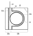
- FIG. 2 is a diagram showing a configuration of an optical fiber package of the present invention.
- the package 10 of the present invention is composed of a first sheet portion and a second sheet portion, that is, two upper and lower layers of sheets sandwiching the optical fiber 15.
- the outer peripheral portion of the package 10 may be closed except for the portion where the end portion 13 of the optical fiber 15 comes out, or a part of the outer peripheral portion may be closed.
- the upper and lower sheets may have different sizes and shapes.
- the entire optical fiber may be contained in a closed bag-shaped package (storage portion) including the other end portion of the optical fiber.
- the package may have a structure in which one sheet is folded back to form a two-layer sheet, or a structure in which two separate sheets are bonded and fixed at a holding portion or a peripheral portion described later.
- a box-shaped form having side surfaces may be used instead of the form of a two-layer sheet. In the case of the box-shaped form, it is easier to separate the perforations described later by extending them to the side surface.
- the sheet is translucent or transparent so that the optical fiber to be packed can be seen.
- the structure may be such that a window is opened in a part of the sheet.
- only one sheet of two layers of sheets (first sheet portion and second sheet portion) sandwiching an optical fiber, or a part of one sheet or a part of both sheets is translucent.
- the internal optical fiber can be seen.
- translucency there is no limitation on the color or its transparency as long as the position and shape of the optical fiber inside the package can be seen from the outside. Therefore, as the sheet material, resin, metal leaf, non-woven fabric, cloth or mesh made of natural fiber or chemical fiber can be used.
- a material of a portion where the optical fiber can be visually recognized may be combined with another material of another portion.
- These sheet materials may have conductivity and flame retardancy.
- holes or slits may be provided on the sheet surface so that the position and shape of the optical fiber inside can be confirmed.
- polyimide, fluororesin or the like can be used as the sheet material in consideration of the case where the package integrated with the optical module is exposed to a high temperature environment such as a reflow process.
- the package 10 of the present invention has holding portions 11a and 11b so that the optical fiber 15 can be held in a state of being wound in a circular shape inside the package 10, and holding portions having various shapes are provided as described later in FIG. You can choose.
- the holding portions 11a and 11b are formed by joining the upper and lower sheets to each other while holding the optical fiber by adhesive, double-sided tape, crimping, thermocompression bonding, braiding, or the like. Further, the holding portions 11a and 11b may be formed by fixing between the two sheets using a member different from the sheets.
- the term “braid” refers to a form in which a part of the target material is cut out and the cut-out portion is inserted into the corresponding cut and fixed, as is known for, for example, a stapler without a needle.
- a part of one sheet portion can be cut out into a fixed shape such as a strip shape and folded (knitted) into a cut (for example, a ladder-shaped cut) of the other sheet portion. Therefore, the knitting includes various forms in which a part of the two sheets sandwiching the optical fiber in the main body portion is mechanically entwined so that the state similar to that of joining the two sheets can be obtained.
- the space formed by the two sheets and the holding portion serves as a storage portion for accommodating the optical fiber therein.
- the package 10 of FIG. 2 is composed of a linear holding portion 11a and a continuous linear holding portion 11b including an arc shape, but the holding portion is not necessarily a continuous linear shape as long as the optical fiber can be held. There is no need. That is, it may be an array of holding portion elements having a short cut, or the point-shaped holding portion elements may be connected to form a shape as shown in the holding portions 11a and 11b of FIG. 2 as a whole.
- the retainer is formed by the arrangement of the smaller retainer elements described above, the number of retainer elements is not limited as long as the optical fiber can be held in a circular or elliptical shape.
- a material or structure that increases friction with the optical fiber may be used for the inner surface of the sheet in contact with the optical fiber, or the inner surface may be surface-processed.
- the package 10 of the present invention includes a cutting guide portion formed between the two holding portions 11a and 11b along the outer circumference of the removing portion 12a to facilitate cutting.
- a separable structure such as a perforation 16 allows the package 10 to be separated into a removal portion 12a and a remaining portion 12b at the perforation 16 as a boundary.
- the removing portion 12a can be completely separated from the remaining portion 12b of the main body of the package 10.
- the perforation 16 is formed only on one sheet, it is desirable that the crease structure is provided at a position corresponding to the perforation of the other sheet.
- One sheet is cut from the main body by the perforation 16, and the removal portion 12a of the other sheet is folded back by the crease structure to expose the optical fiber 15 from the package 10.
- perforations or cuts may be made at both ends of the crease structure so that the crease structure can be easily folded back, or perforations can be adopted as the crease structure.
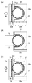
- FIG. 3 is a diagram illustrating the function of the removing portion in the package of the present invention.
- FIG. 3A shows a state before the removal portion 12a is separated from the package, and both ends 13 and 14 of the optical fiber 15 packed in the package are exposed to the outside of the package. It is different from the configuration of.
- an optical connector, an optical receptacle, or the like may be connected to any of the ends of the optical fiber outside the package.
- FIG. 3B shows the state of the package in which the removal portion 12a is separated by the perforations 16 formed on both sides of the package 10 and only the remaining portion 12b remains.
- the removal portion 12a from the package 10 can be separated, for example, immediately before the step of connecting the optical fiber to the optical module.
- the end portions 13 and 14 of the optical fiber are exposed to the outside of the package, but the main body of the optical fiber 15 is still held in a constant circular or elliptical shape.
- FIG. 3B an example is shown in which the entire removing portion 12a is separated from the package main body along the perforation 16, but the configuration of the removing portion is not limited to this.
- the position of the perforation 16 is preferably a position where the optical fiber is exposed in a crescent shape when the optical fiber 15 is separated so that the optical fiber 15 can be easily taken out.
- the shape of the removing portion 12a forms an opening in which the optical fiber 15 can be easily taken out while maintaining the shape of the main body of the optical fiber 15 when removed.
- the configuration is not limited to the configuration (a) of FIG. A configuration different from that shown in FIG. 3A, in which the removing portion 12a is formed by a linear perforation in the vicinity of one side of the package, can be obtained.
- a perforation 17 is formed in the vicinity of the inside of the circular shape of the optical fiber main body 15 along the shape of the holding portion 11b. Can be provided.
- the linear perforations 16 remain as in FIG. 3A.
- the area inside the holding portion 11b of the upper sheet is removed in a U shape integrally with the removing portion 12a by the two perforations 16 and 17 having different shapes, and an opening may be provided near the center portion of the package. it can.
- the main body 15 of the optical fiber having a circular shape or an ellipse is elastically pressed against the holding portion. ..
- the optical fiber retains its original shape before the removal portion 12a is separated and does not pop out of the package.
- the wider the opening the easier it is to access the optical fiber, but the risk of the optical fiber popping out of the package increases. Therefore, it is preferable that at least half or more of the optical fiber main body (circular portion) is covered with the upper layer sheet in the state where the removing portion 12a is separated.
- the perforations 17 are provided inside or directly above the optical fiber main body of at least half or more. It should be noted that a part of the perforation 17 may protrude beyond the holding portion 11b.
- the removal portion in the package of the present invention includes not only the one in which the entire removal portion is separated from the main body portion of the package, but also the one in which at least a part thereof is removed or deformed.
- the above-mentioned removing portion is configured to remove or deform a part of the two-layer sheet (first sheet portion and second sheet portion) of the main body portion of the package, but is further a cover sheet.
- An opening may be provided in advance on one of the two-layer sheets of the main body, and the cover sheet may be fixed on the main body so as to cover the opening.
- a cover sheet that seals the opening of one sheet can be attached in advance, and the cover sheet can be peeled off from the main body when the optical fiber is taken out. Even with the configuration further provided with the cover sheet in this way, the same function as the above-mentioned removing portion can be achieved.
- the entire optical fiber is wound in the package while the end or the whole of the optical fiber can be accessed by separating or deforming a part thereof. Can be maintained in that state. Therefore, the exposed end allows the optical fiber to be pulled out linearly from the package, and the optical fiber can be taken out while maintaining the circular shape.
- the optical fiber maintaining the circular shape is temporarily fixed by some method so that the optical fiber does not become a straight line.
- one optical fiber may be stored in each storage portion by using a package having a plurality of storage portions. By laminating and fixing two or more sheets at the peripheral portion, a package having a plurality of storage portions can be formed. Further, a single sheet material may be folded in a bellows to form a plurality of storage portions.
- the above-mentioned excellent features of the package of the present invention are further exhibited not only in such a storage form but also in a state in which the optical fiber is connected to the optical module as shown in FIG. To.
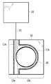
- FIG. 4 is a diagram showing a configuration of a second embodiment of the optical fiber package of the present invention.
- the optical module 20 is composed of an optical module 20, an optical fiber 15 connected to the optical module 20, and a package 10 for accommodating the optical fiber 15.
- the end portion 13 of the optical fiber exposed to the outside of the package 10 is directly connected to the optical module 20.
- FIG. 4 shows one aspect of the second embodiment, showing an optical module 20 completed by incorporating an optical fiber 15 for external connection, and a state in which the optical fiber 15 is housed in a package 10. There is.
- the optical fiber 15 is connected to an optical element in the optical module via a connecting portion on the side surface (connecting surface) of the optical module 20.
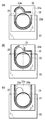
- FIG. 5 is a diagram showing various morphological examples of the package fixed on the optical module.
- (A) to (c) of FIG. 5 show different configuration examples of the removal portions 22a, 22b, and 22c in the package 10, and is a top view of the state in which the package 10 is fixed to the upper surface of the optical module 20. Is.
- at least a part of the removal portion is fixed beyond the region of the upper surface (connection surface 26) to which the optical fiber of the module 20 is connected.
- the package 10 is fixed on the optical module 20 with double-sided tape, an adhesive, or the like at a position where a part of the package 10 protrudes from the upper surface of the optical module.
- the package 10 may be fixed between the package and the optical module 20 by forming some shape such as a hole in the sheet of the main body and hooking it on the protrusion (hook) of the optical module. Therefore, the package 10 can be fixed on the optical module by forming some structure corresponding to the hook structure of the optical module on the main body of the package.
- the structure of the portion through which the optical fiber passes from the inside to the outside of the package is not specified, but a cut or an opening for letting the optical fiber out may be provided in a part of the package. Just do it.
- the removal portion 22a also includes a cap-shaped holding portion 21a in which a semicircle and a straight line are connected to hold a curved portion from the circularly wound optical fiber main body portion to the side surface of the optical module. Even if the cutting guide portion shown by the dotted line, for example, the removing portion 22a is separated at the perforation 25, the wound portion which is the main body portion of the optical fiber is maintained in its form by the holding portion 21b. Therefore, using the exposed portion of the optical fiber as a clue, the optical fiber can be taken out while maintaining the wound state in the package.
- the removing portion 22a is completely removed, but it may be formed only on one (upper layer) sheet. In this case, the upper sheet of the removal portion is turned up to expose the optical fiber.
- the right half of the package 10 is the removing portion 22b, and the holding portion 21 is formed so as to surround the wound portion of the optical fiber so that the optical fiber can be smoothly shaped. It is an integral part that surrounds the entire optical fiber.
- FIG. 5B shows an example in which the perforation 25 is located in the center of the package as one of the modified examples of the configuration of the removing portion, but the position and shape of the perforation can be further deformed.
- the length of the perforation is made smaller than half the size of the removing portion 22b, the optical fiber can be more reliably maintained in a circularly wound state.
- the perforations diagonal to the outer peripheral side of the package or making them curved, it is possible to easily separate the removal portion 22b while maintaining easy access to the optical fiber main body, and the optical fiber. It is possible to more reliably maintain the wound state of.
- the package 10 has a single U-shaped holding portion 21, and the removing portion 22c is located in the inner region of the holding portion 21.
- the removing portion 22c has linear perforations 25a and 25b at two positions on the upper sheet so that only the sheet on the upper side of the package 10 is turned up.
- the line connecting the end portions of the perforations 25a and 25b is a crease when the removal portion 22c is turned up.
- the end portions of the perforations 25a and 25b are located on the upper surface of the optical module at a position where the optical fiber main body is exposed in a crescent shape when the removal portion 22c is turned up.
- the optical fiber can be taken out from the opening formed by turning up the removing portion 22c along the two perforations 25a and 25b, and at the same time, the optical fiber remains wound in the package. Can maintain the state of. Even when the removal unit 22c is turned up and deformed, the wound form of the optical fiber is maintained, and the optical fiber is taken out of the package in the wound shape, which is suitable for the work of the next process. Processing can be performed.
- the perforations may be further extended from the ends of the linear perforations 25a and 25b shown in FIG. 5 (c) to form a continuous integrated perforation.
- the ends of the perforations 25a and 25b can be connected by a straight line to form a U-shaped perforation.
- a continuous integrated perforation is formed inside the holding portion along the circular shape of the optical fiber, a U-shaped perforation is obtained.
- a part of the perforation may be projected to the outside of the holding portion.
- the entire removal portion including the upper and lower sheets has been described as being integrally separated, but as in the case of (c) of FIG. 5, the lower sheet of the package
- the removal portion may be configured so that only the upper sheet is folded back (removed) at the perforation boundary. That is, the removal portion may be configured such that a portion of the area of either the first sheet portion (upper side) or the second sheet portion (lower side) of the main body portion of the package is removed or deformed.
- the optical fiber protruding from the inside of the optical module 20 can be compactly stored and packed in the package 10 fixed to the upper surface of the optical module 20. ..
- the optical module with an optical fiber as shown in FIG. 1 can be safely handled without worrying about damage to the optical fiber, and can be handled in a compact form.
- the packaging form in which the optical module and the package are integrated as shown in FIG. 5 facilitates the handling of the optical module in the transportation of the optical module and the subsequent assembly process to the transceiver. Further, it is possible to prevent a decrease in transceiver quality and manufacturing yield and a decrease in production efficiency due to damage to the optical fiber or the like. Further, the storage portion of the package after the optical fiber is taken out from the package 10 can be reused as a temporary storage portion for storing the optical fiber of other optical components and the like.
- the holding portion 21 located on the upper surface of the optical module 20 is U-shaped according to the shape of the main body of the optical fiber.
- the shape of the holding portion 21 protruding from the upper surface is optimized so that the optical fiber can be handled as easily as possible when the removing portion is separated, depending on the position and shape of the removing portions 22a, 22b, and 22c. ..
- the shape of the holding portion of (a) is preferable in (a) to (c) of FIG.
- the holding portion (a) of FIG. 5 has a shape along a natural routing route of the optical fiber from the main body of the optical fiber wound in a circular shape to the side surface (connection surface 26) of the optical module.
- a cap-shaped (hat-shaped with a brim) holding portion 21a in which a U-shape and a straight line are connected is formed.
- the cap-shaped holding portion 21a and the U-shaped holding portion 21b are separated by the perforations 25, and the cap-shaped holding portion 21a itself is not divided.
- the holding portion of the removing portion 22b is divided near the crown of the cap, and a part of the cap shape and the U-shaped portion are connected to form a holding portion.
- the optical fiber follows the natural routing route of the optical fiber as in the configuration of (a) of FIG. It is held in a shape that does not burden the user.
- the removal unit 22b is separated (the state after removal)
- almost all of the optical fiber main body is located on the optical module, so that the optical fiber can be used as compared with the configuration of FIG. 5A. Inferior in accessibility.
- the holding portion is simplified to a U shape without using the cap shape.
- the shape of the optical fiber from the optical module is not sufficiently maintained in the state before removal, the shape of the optical fiber is maintained in FIG. 5 (a). ) Is inferior. In terms of accessibility to the optical fiber after removal, it is equivalent to the configuration of FIG. 5A.
- the width of the package 10 is substantially the same as that of the optical module in the transceiver manufacturing process. Can be treated as a thing.
- the optical module in the state shown in FIG. 5 can be mounted on the substrate of the transceiver before reflow by the automatic mounting machine.
- the width of the package 10 is preferably equal to or less than the width of the optical module, but there may be no problem even if it is larger than the width of the optical module depending on the function of the automatic transfer machine. Therefore, the width of the package 10 may be about the width of the side surface of the optical module where the optical fiber does not come out.
- DSP digital signal processor
- the outer shape of the main body of the package shown in each of FIGS. 5 (a) to 5 (c) has been described as having a rectangular shape, but a part thereof is curved along the wound portion of the optical fiber. It may be U-shaped as a whole.
- the package may include a plurality of optical fiber storage portions. For example, if the outer peripheral portions of three or more sheets are fixed by sticking them together, two or more overlapping storage portions can be formed, and a plurality of optical fibers extending from the optical module can be compactly stored at the same time. Can be done. Further, a single sheet material may be made into a so-called bellows fold by a repeated structure of mountain fold and valley fold, and a storage portion may be formed for each bellows. One fiber can be stored in each of the valley folds, and a plurality of optical fibers can be easily stored.
- the present invention is a package for accommodating at least one wound optical fiber protruding from a side surface in the optical module and the optical fiber in the optical module, the first sheet portion and the second.
- a removal portion which is a region of a part of the first sheet portion or the second sheet portion including a part of the sandwiched optical fiber and can be removed or deformed from the main body portion.
- the package is fixed to the upper surface of the optical module, and the width of the package is about the width between the side surfaces of the optical module where the optical fiber does not come out. It can be implemented as a module.
- the optical fiber which is difficult to handle, is shaped more compactly than the configuration shown in FIG. Therefore, even when the optical module is temporarily stored on a tray or the like, it is easy to handle, saves space, and can be stored at high density. Further, because of the structure of the removing portion and the holding portion peculiar to the present invention, even when the optical fiber is taken out from the package, the state of being wound inside the package can be maintained. When processing the end of the optical fiber or connecting it to other parts of the transceiver, the optical fiber may be released from the wound state immediately before the necessary work. The complexity of the transceiver assembly work due to the careful handling required for the linearly extended optical fiber can be eliminated, and the transceiver assembly process can be made more efficient.
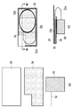
- FIG. 6 is a diagram showing a more detailed configuration of the package fixed on the optical module.
- FIG. 6A is a top view of a packaging form having the same configuration as FIG. 5C
- FIG. 6B is a cross-sectional view taken along the VIB-VIB'line.
- the optical fiber 24a vertically protruding from the side surface of the optical module 20 is folded back toward the optical module side with the minimum curvature toward the upper surface of the optical module, and is housed in the package 10 as it is. Inside the package 10, the optical fiber 24b is held in a circular shape 24 by a U-shaped holding portion.
- the package 10 and the upper surface of the optical module 20 can be fixed with double-sided tape or an adhesive.
- the entire contact surface may be brought into close contact with the package 10 and the optical module 20 to be fixed, or a part of the contact surface may be brought into close contact with the optical module 20.
- the area to be removed of the sheet including the above-mentioned removing portion should not be fixed in close contact. Therefore, in the configuration shown in FIG. 6, the optical fiber of the optical module with the optical fiber is housed in the package 10 leaving a certain length as shown in FIG. 4, and then the direction of the package is changed and the optical fiber is folded back. Obtained by fixing the package on an optical module.
- the structure of the portion through which the optical fiber passes from the inside to the outside of the package is not specified. An opening may be provided.
- FIG. 7 is a diagram showing a more specific configuration example of the package of the second embodiment.
- FIG. 7A shows the components constituting the package of the second embodiment before assembly.
- An optical fiber 32 (shown only partially) is connected to the optical module 30.
- the above-mentioned notched portion of the lower sheet 34 becomes an opening through which an optical fiber passes when the package is constructed.
- a rectangular upper sheet 33 having the same outer circumference as the lower sheet 34 and having no removing portion is shown.
- FIG. 7B is a view of the configuration of the package integrated with the optical module by combining the above-mentioned components as viewed from above the optical module.
- the periphery of the lower sheet 34 and the upper sheet 33 is bonded by a holding portion 35.
- the holding portion 35 shows an example of a rectangular shape instead of a U shape.
- the optical fiber is wound in a substantially elliptical shape by a rectangular holding portion 35.
- the optical fiber passes from the wound main body portion 32b through the curved portion 32a, passes through the opening, and reaches the side surface (connecting surface) of the optical module.
- the perforation 36 shown by the dotted line of the package is located on the left side of the drawing of the optical module 30, and the left side of the perforation 36 can be separated as a removing portion.
- the holding portion is formed by laminating two sheets in a shape that follows the outer shape of the wound portion of the optical fiber, instead of laminating the outer periphery of the sheet as shown in FIG. 7 (b). You can also do it. As a result, it is possible to form a holding portion having a U-shape or a combination of the U-shape and the cap shape illustrated in FIGS. 5 and 6.
- FIG. 7 (c) is a view of the cross section of the top view of (b) taken along the line VII-VII'viewed from the upper side to the lower side of (b).
- the thickness (vertical) direction of the package is enlarged to make the structure easier to see.
- the upper sheet 33 and the lower sheet 34 are combined by the holding portion 35 to form a bag shape.
- the wound portion 32b of the optical fiber is housed and held in a bag-shaped package.
- the upper sheet 33 and the lower sheet 34 may be in close contact with each other, or may have a gap as long as the shape of the optical fiber can be maintained. If an appropriate length is set as the portion corresponding to the curved portion 32a, the optical fiber 32 is in the state of (b) of FIG. 7 from the three components 30, 33, 34 of FIG. 7 (a). The work of packing is not difficult.
- the position of the package and the holding position of the optical fiber may be shifted so that the radius of curvature of the curved portion 32a becomes large.
- the light is retained even if the center position of the package is shifted in the direction away from the connection between the optical fiber and the optical module in the direction perpendicular to the direction in which the optical fiber exits from the side surface (connection surface). Even if the center position of the fiber body is shifted from the center of the package body in a direction away from the connection portion of the optical module, the bending of the curved portion 32a can be loosened.
- the present invention also has an aspect as a method of packing and storing an optical module. That is, in the packing method of the optical module in which the optical fiber comes out from the side surface, first, a step of shaping the optical fiber in a wound state having a predetermined winding diameter size is performed. Next, the step of sandwiching the optical fiber between the upper and lower sheets constituting the main body is performed. In this sandwiching, the holding portion described in the above embodiment is formed, and the upper and lower sheets (the first sheet portion and the second sheet portion) are joined to form the main body portion, and the package is completed. ..
- a columnar auxiliary tool may be used when winding the optical fiber to store the optical fiber in the package.
- the bundle of the wound optical fibers is removed from the auxiliary tool and inserted between the upper and lower sheets (first sheet portion and second sheet portion) of the main body portion configured in a bag shape to form a bag.
- a holding portion may be formed so as to close the opening.
- a bundle of optical fibers wound up from an opening formed on one sheet may be stored in the main body, and then another sheet material (cover sheet) may be adhered to the opening. It should be noted that this bonded sheet material functions as a remover for the package of the present invention.
- the step of fixing this package to the upper surface of the optical module with an adhesive or double-sided tape.
- an optical module in which the optical module in which the optical fiber protrudes from the end and the packaged optical fiber are integrated can be obtained.
- the package size is such that the width of the package is about the width of the side surface of the optical module where the optical fiber does not come out.
- the size of the long side of the optical module 30 and the widths of the upper sheet 33 and the lower sheet 34 are the same, and even if they are integrated with the package, they are substantially light.
- the width of the module is the same. Therefore, the optical module can be grabbed by the automatic mounting machine and mounted on the substrate of the transceiver in the same manner as other electric components such as ICs and DSP chips. If a package having an opening in the center of the upper and lower sheets is used, the upper surface of the module can be directly sucked by the automatic mounting machine.
- the weight of the entire optical module including the package can be balanced and the parts can be stably mounted on the substrate without tilting.
- Optical module can be mounted on.
- the periphery of the opening may be fixed.
- the winding diameter in the winding state of the optical fiber can be freely set depending on the configuration and shape of the holding portion. Therefore, the optical fiber stored in the package can be shaped with a winding diameter according to the user's intended use in the subsequent process and stored in the package. For example, in the transceiver assembly process, extra length processing of the optical fiber according to the transceiver configuration is required.
- the package of the present invention makes it possible to pack and store an optical fiber while performing flexible forming according to a user's request in a subsequent process.
- the present invention can be used for an optical module in an optical communication system.
Landscapes
- Engineering & Computer Science (AREA)
- Mechanical Engineering (AREA)
- Packages (AREA)
- Packaging Of Annular Or Rod-Shaped Articles, Wearing Apparel, Cassettes, Or The Like (AREA)
- Light Guides In General And Applications Therefor (AREA)
- Optical Couplings Of Light Guides (AREA)
Abstract
本発明は、少なくとも一端を有する光ファイバの梱包形態を提供する。光ファイバは、光ファイバを巻き取られた状態で保持する保持部と、一部が変形または除去される除去部を有するパッケージによって収納され、梱包される。この本発明の梱包形態において、パッケージは、所定の長さを有し両端を持つ光ファイバの単体を梱包することもできるし、一端が光モジュールなどの光回路やコネクタ等に接続された光ファイバを梱包することもできる。パッケージによって梱包される光ファイバは、1本でも良いし、複数本の光ファイバであっても良い。梱包される光ファイバの端部には、光コネクタが接続されていても良い。端部には、複数の光ファイバをアレイ状に並べるコネクタが接続されていても良い。
Description
本発明は、光ファイバに関する。より具体的には、光伝送装置等で使用される光ファイバのパッケージに関する。
100Gbps超の光伝送を実現する「デジタルコヒーレント光伝送技術」の普及が進み、光ネットワークの高速大容量化を実現している。それに伴って、「デジタルコヒーレントトランシーバ」などのデジタルコヒーレント光伝送用装置の小型化が求められている。光伝送用装置では、複数のチャンネルの光信号処理を行い、着脱が可能なデジタルコヒーレントトランシーバ(簡単のため以下トランシーバと言う)の仕様が規定されている。トランシーバの消費電力やサイズは、標準化団体のOIF(The Optical Internetworking Forum)等によって規格が決定されている。
OIFの規格では、第1世代の100Gbpsトランシーバの幅が80mm程度であったものが、次世代の400Gbpsトランシーバでは、幅は20mm程度にまで小型化されている(CFP8、OSFP規格等)。これに伴い、トランシーバを構成する主な要素の1つである光送受信デバイスにも、10~20mm角程度のサイズが要求されている。光送受信デバイスは、多層配線基板上に光部品や電気部品を搭載したモジュールであって、光変調器やコヒーレント受信機などの光送受信機能を集積化したものである。
光送受信デバイスおよびトランシーバの間の入出力インタフェースを光接続するために、光ファイバが使用される。トランシーバを製造するにあたっては、光送受信デバイスに接続された光ファイバは、後工程で利用するのに適当な長さに切断され、光送受信デバイスと光ファイバが一体となった形態で取り扱われることが多い。したがって、光ファイバが接続された状態の光送受信デバイスを検査したり、トランシーバへの組み込みをしたりする工程が実施される、これらの工程には、破損しやすい光ファイバに対して慎重な扱いが求められる。
光ファイバの収納方法に関して、例えば特許文献1がプラスチックケース利用した光ファイバの収納法の形態を開示している。また特許文献2は、一般的な用途の光ファイバの自体の余長部分の処理方法を開示している。さらに特許文献4は、光ファイバ増幅器における防湿効果を有する極めて長い光ファイバの収納形態を開示している。また特許文献5は、光ファイバの余長部分を多重交差なしに処理する多層シートを、特許文献6は、コネクタが接続された複数の光ファイバを保持して梱包する形態が開示している。光ファイバの光モジュールにおける配線に関しては、特許文献3は、複数の空間光学部品から構成される大きな光モジュール内で、光ファイバの余長部分を処理する形態を開示している。
トランシーバおよびその中に組み込まれる光送受信デバイスに対する小型化の要請により、光送受信デバイスと共に使用される光ファイバを、安全で効率的に作業性良く取り扱うことのできる仕組みが求められている。上述の従来技術では、光ファイバ単体の収納形態や、比較的大きな光モジュールにおける光ファイバの取り扱いや保存などを助ける収納、梱包等の形態が開示されている。これらのいずれの従来技術も、最大幅が20mm程度のトランシーバや、1辺が10~20mm程度に小型化された光送受信デバイスで使用される光ファイバにおける次のような問題に対処できるものではなかった。
上述のCFP8、OSFP規格のサイズの光モジュールの組立の際には、光モジュールの内部と外部の接続のために、1本以上の光ファイバを光モジュールに接続する必要がある。光ファイバを光モジュールに接続する際には、例えば特許文献6の図1などに示されているようなシート状の梱包ケースから光ファイバを取り出して、光モジュールに実装する。通常、梱包ケースのシート1面を剥がして開封し、光ファイバをケースから取り出す。この開封の際、光ファイバの弾性のため光ファイバの一部がケースから飛び出して作業が煩雑になり、ファイバが破損する恐れがあった。また光ファイバを光モジュールに取り付けた後で、一旦広がって伸びた光ファイバを再度巻き取るなどしないと、光モジュールを安全で効率的に保管や輸送することはできない。結果として、光モジュールを組立した後の次工程(検査、測定、輸送、装置への搭載、装置組立など)のために、作業時間と手間が増えてしまう問題があった。
図1は、トランシーバ内に搭載される光モジュールの構成例を示した図である。図1の(a)は、光モジュール1に光ファイバを取り付けて組立が終わった段階の構成を示す。一辺が最大10~20mm程度の大きさの光モジュール1から、300~400mmの長さの光ファイバ2は、その弾性のためにほぼ真直ぐに伸びた状態となる。光ファイバ2の端部には、光モジュールの用途に応じた形態の光コネクタ3が付けられている場合も多い。光モジュール1の機能によっては、図1の(b)に示したように複数本の光ファイバ2a~2dが接続された状態の場合もある。複数本の光ファイバ2a~2dの場合も、各々の光ファイバの端部には光コネクタ3a~3dが付けられている。
図1の(a)および(b)のような状態の光モジュールを、製品として梱包して出荷したり、トランシーバへ搭載する次の製造工程のため搬送したりするためは、光ファイバの余長部分を安全に処理する必要がある。例えば、伸びた光ファイバを再度巻き取ったり、光ファイバが破損しないような大型のトレイなどに保管したりするなどの工程が必須となる。これらの工程のために特許文献2に開示されているような粘着性のあるシートを使うこともできるが、被覆の無い120μm程度の非常に細い光ファイバでは、再梱包と取り出しが難しく、光ファイバが取り扱い中に破損する可能性も高くなる。光ファイバが跳ね上がることなく容易に光ファイバを取り出すことのできるファイバ梱包形態が必須となる。上述のように光ファイバの取り扱いは、光部品としての光ファイバ単体の搬送、また光モジュールへの組み込み、光ファイバ付き光モジュールの検査、搬送、保管さらには光ファイバ付き光モジュールをトランシーバへ搭載する製造工程などの様々な場面に渡る。これらの各場面において、安全かつ作業性良く効率的に光ファイバを扱うことのできる仕組みが求められている。
本発明はこのような問題に鑑みてなされたものであって、その目的とするところは、作業性が良く効率的に光ファイバを扱える新規な梱包形態を提供することにある
このような目的を達成するために、本発明の1つの実施態様は、第1のシート部および第2のシート部によって、少なくとも1本の巻き取られた光ファイバを挟み込む本体部と、前記第1のシート部および前記第2のシート部を接合し、前記光ファイバの巻き取られた部分を囲むように形成された保持部と、挟み込まれた前記光ファイバの一部を含む、前記第1のシート部または前記第2のシート部の一部の領域であって、前記本体部から除去しまたは変形させることが可能な除去部とを備えたことを特徴とする光ファイバのパッケージである。
上記パッケージでは、前記除去部が除去されまたは変形された状態で、前記光ファイバの前記巻き取られた部分の形態が維持される。また、前記保持部は、前記巻き取られた光ファイバの外周形状に沿った形で形成される。
別の実施態様は、上述のパッケージにおいて、前記第1のシート部および前記第2のシート部と同形の、1つ以上のシート部をさらに備え、前記シート部の隣接する2つによって、複数の巻き取られた光ファイバの各々が挟み込まれ、前記複数の巻き取られた光ファイバを一体に収納できる前記本体部を備えることができる。
また上記パッケージでは、前記保持部は、前記第1のシート部および前記第2のシート部の間の接着、圧着、熱圧着または編み込みによって形成され得る。ここで編み込みとは、例えば針なしのステープラーなどで知られているような、対象材料の一部を切り出して、切り出し部分を対応する切れ目に差し込んで固定するような形態を言う。具体的には、一方のシート部の一部を一定形状に切りだして、他方のシート部の切れ目に折り込むことができる。したがって、本体部において光ファイバを挟み込んで相対するシートの一部分を機構的に絡めることによって接合状態に等しくなるような様々な形態を含む。
上述のパッケージは、前記本体部の最上面に位置するシート部の中央に、前記巻き取られた光ファイバの外周以下の大きさの開口部を備え、当該開口部を覆うカバーシートを備えることができる。
上述の各パッケージは、前記除去部の外周に沿って形成され、切断を容易にする切断ガイド部(ミシン目)をさらに備えることもできる。切断ガイド部は、ミシン目以外に、ガイド部に沿って一方向に切断が容易になっている構造を持っていれば良い。好ましくは、前記切断ガイド部の両端に切り欠き部を設けることもできる。
さらに上述のパッケージでは、前記本体部の前記第1のシート部および前記第2のシート部は、単一のシート材で構成されることができる。さらに上述のパッケージは、前記除去部は、前記第1のシート部および前記第2のシート部の前記一部の領域が一体に除去されるよう構成されることができる。
また上述のパッケージは、前記除去部は、前記第1のシート部または前記第2のシート部のいずれかの前記一部の領域が除去されるかまたは変形されるよう構成されることもできる。
本発明の別の実施態様は光モジュールにおいて、前記光モジュール内の側面から出た少なくとも1本の巻き取られた光ファイバと、前記光ファイバを収納するパッケージであって、第1のシート部および第2のシート部によって、前記光ファイバを挟み込む本体部と、前記第1のシート部および前記第2のシート部を接合し、前記光ファイバの巻き取られた部分を囲むように形成された保持部と、挟み込まれた前記光ファイバの一部を含む、前記第1のシート部または前記第2のシート部の一部の領域であって、前記本体部から除去しまたは変形させることが可能な除去部とを有する、パッケージとを備え、前記パッケージは前記光モジュールの上面に固定され、前記パッケージの幅が、前記光モジュールの前記光ファイバの出ていない側面間の幅程度であることを特徴とする光モジュールである。上述の光モジュールでは、前記除去部が除去されまたは変形された状態で、前記光ファイバの前記巻き取られた部分の形態が維持される。
以上説明したように、作業性が良く効率的に光ファイバを扱える新規なパッケージ、光モジュールを実現できる。
本発明は、少なくとも一端を有する光ファイバの梱包形態を提供する。光ファイバは、光ファイバを巻き取られた状態で保持する保持部と、一部が変形または除去される除去部を有するパッケージによって収納され、梱包される。この本発明の梱包形態において、パッケージは、所定の長さを有し両端を持つ単体または複数の光ファイバを梱包することもできるし、一端が光モジュールなどの光回路やコネクタ等に接続された光ファイバを梱包することもできる。パッケージによって梱包される光ファイバは、1本でも良いし、複数本の光ファイバであっても良い。梱包される光ファイバの端部には、光コネクタが接続されていても良い。端部には、複数の光ファイバをアレイ状に並べるコネクタが接続されていても良い。
1本以上の光ファイバは、パッケージの全体を構成する本体部(シート材)によって挟み込まれる。以下の説明では、パッケージの全体を本体部と称する。本体部は、第1のシート部および第2のシート部の2層のシート材を含む。本体部は、第1のシート部および第2のシート部を相互に貼り合わせるとともに、パッケージ内で光ファイバの形状を維持する保持部を有する。さらにパッケージの一部は、簡単に切り離したり変形させたりできる除去部を備えている。光ファイバは、除去部をパッケージから切り離しまたは変形させた状態でも、保持部によって一定の形状を維持できる。光ファイバの端部は、パッケージ内に収まっていても良いし、パッケージ外に出ていても良い。光ファイバの端部がパッケージ内に含まれている場合は、その端部がパッケージの内部で固定されていても良い。光ファイバの端部がパッケージ外に出ている場合は、光ファイバの柔軟性によって一定長さだけ光ファイバを引き出すこともできる。
上述の第1のシート部および第2のシート部に加えて、除去部として機能するカバーシート部を備えることもできる。このとき、カバーシート部を除去することで第1のシート部または第2のシート部の一部に開口部が形成される。
光モジュールに光ファイバが接続された状態で、本発明の梱包・収納形態を利用することもできる。パッケージは、梱包される光ファイバが巻き取られた部分から適切な湾曲部を経て光モジュールの接続部へ至るように、パッケージ内部から外部へ光ファイバを通す開口部を有する。パッケージは、後に着脱可能なように、光モジュールの筐体の上面に固定される。パッケージの幅は、光モジュールの一辺の長さ程度であるのが好ましい。
上述のように、本発明は両端を有する1本以上の光ファイバのみを収納するパッケージとして実施できる。また、光ファイバが接続された光部品(例えば光モジュール)の光ファイバを、パッケージ内に収納し、この光部品およびパッケージを一体で取り扱うことができる。以下、具体的な構成例とともに本発明の光ファイバの梱包形態について説明する。以下の説明では、梱包形態を単に「パッケージ」と呼ぶが、本発明は光ファイバの梱包・収納方法としての側面も持つことに留意されたい。また以下の説明では、光ファイバを「収納」すると言う表現も用いるが、これは「梱包」すると同じ意味で使用される。
[第1の実施形態]
図2は、本発明の光ファイバのパッケージの構成を示す図である。本発明のパッケージ10は、第1のシート部および第2のシート部、すなわち光ファイバ15を挟む上下2層のシートで構成される。パッケージ10の外周部は、光ファイバ15の端部13が出る部分を除いて閉じていても良いし、外周部の一部が閉じていても良い。上下のシートが異なる大きさ、形状であっても良い。また、図2のように光ファイバの他方の端部も含めて、閉じた袋状のパッケージ内(収納部)に光ファイバの全体が収まっていても良い。したがってパッケージは、1枚のシートを折り返すことによって2層のシートを形成した構造でも良いし、2枚の別々のシートを後述する保持部または周辺部で貼り合わせて固定した構造のものでも良い。また2層のシートの形態ではなく、側面を有する箱形状の形態でも良い。箱形状の形態の場合、後述するミシン目を側面まで延長して形成した方が切り離ししやすい。
図2は、本発明の光ファイバのパッケージの構成を示す図である。本発明のパッケージ10は、第1のシート部および第2のシート部、すなわち光ファイバ15を挟む上下2層のシートで構成される。パッケージ10の外周部は、光ファイバ15の端部13が出る部分を除いて閉じていても良いし、外周部の一部が閉じていても良い。上下のシートが異なる大きさ、形状であっても良い。また、図2のように光ファイバの他方の端部も含めて、閉じた袋状のパッケージ内(収納部)に光ファイバの全体が収まっていても良い。したがってパッケージは、1枚のシートを折り返すことによって2層のシートを形成した構造でも良いし、2枚の別々のシートを後述する保持部または周辺部で貼り合わせて固定した構造のものでも良い。また2層のシートの形態ではなく、側面を有する箱形状の形態でも良い。箱形状の形態の場合、後述するミシン目を側面まで延長して形成した方が切り離ししやすい。
シートは、梱包される光ファイバが見えるように少なくとも一部が半透明または透明であるのが好ましい。また、シートの一部に窓を開けた構造であっても良い。例えば、光ファイバを挟み込む2層のシート(第1のシート部および第2のシート部)の一方のシートのみ、または、一方のシートの一部もしくは両方のシートの一部が半透明であって、内部の光ファイバを視認可能であれば良い。半透明の場合は、パッケージ内部の光ファイバの位置および形態が外から視認可能である限り、色やその透明度に制限はない。したがって、シート材料としては、樹脂、金属箔、不織布、天然繊維や化学繊維を材料とする布やメッシュ等を利用できる。シート材料として、光ファイバを視認できる部分の材料と、他の部分の別の材料とを組み合わせても良い。これらのシート材料は、導電性や難燃性を備えていても良い。シート材料として不透明な材料を用いる場合には、シート面上に穴やスリットを設け、内部の光ファイバの位置および形態を確認できるようにすることもできる。また後述する別の実施形態では、光モジュールと一体のパッケージが、リフロー工程などの高温環境にさらされる場合を考慮して、ポリイミド、フッ素樹脂等をシート材料として利用することもできる。
本発明のパッケージ10は、その内部で光ファイバ15を円形状に巻き取られた状態で保持できるように保持部11a、11bを有し、図5で後述するように様々な形状の保持部を選択することができる。保持部11a、11bは、接着剤、両面テープ、圧着、熱圧着、編み込み等によって、光ファイバを保持しながら、上下2枚のシートを相互に接合し、形成される。また、2枚のシートの間をシートとは別の部材を用いて固定して、保持部11a、11bを形成しても良い。ここで編み込みとは、例えば針なしのステープラーなどで知られているように、対象材料の一部を切り出して、切り出し部分を対応する切れ目に差し込んで固定するような形態を言う。具体的には、一方のシート部の一部を、例えば帯状などの一定形状に切りだして、他方のシート部の切れ目(例えば、はしご状の切れ目)に折り込む(編み込む)ことができる。したがって編み込みは、本体部において相対して光ファイバを挟み込む2枚のシートの一部分を機構的に絡めることで、2枚のシートを接合したのと同様の状態にできる、様々な形態を含む。上述のように、2枚のシートおよび保持部により形成された空間は光ファイバをその中に収める収納部となる。
図2のパッケージ10は、直線状の保持部11aと、円弧形状を含む連続した線状の保持部11bからなっているが、光ファイバを保持できる限り、保持部は必ずしも連続した線状である必要はない。すなわち、切れ切れの短い保持部要素の配列であっても良いし、点状の保持部要素が連なって全体として図2の保持部11a、11bのような形状を形成していても良い。上述のより小さな保持部要素の配列によって保持部が形成される場合、光ファイバを円形状または楕円状に保持できる限り、保持部要素の数は限定されない。光ファイバが接するシートの内面には光ファイバとの摩擦が大きくなる材料や構造を用いても良いし、内面に表面加工を施しても良い。
本発明のパッケージ10は、2つの保持部11a、11bの間に、除去部12aの外周に沿って形成され、切断を容易にする切断ガイド部を備える。例えばミシン目16などの切り離し可能な構造によって、このミシン目16を境にして、パッケージ10を除去部12aおよび残存部12bに分離できる。除去部の様々な変形例については、図5とともにさらに詳細に述べる。
ミシン目16がパッケージ10の2枚のシートの対応する位置に形成されていれば、除去部12aをパッケージ10の本体の残存部12bから完全に分離することができる。一方のシートのみに例えばミシン目16が形成されている場合は、他方のシートのミシン目に対応する位置に、折り目構造があることが望ましい。一方のシートはミシン目16によって本体部から切断され、他方のシートは折り目構造によって除去部12aが折り返されて、光ファイバ15をパッケージ10から露出させることができる。なお、折り返しをしやすいように折り目構造の両端部にミシン目や切れ目を入れておいても良いし、折り目構造としてミシン目を採用することもできる。
図3は、本発明のパッケージにおける除去部の機能を説明する図である。図3の(a)は、除去部12aをパッケージから切り離す前の状態を示しており、パッケージ内に梱包される光ファイバ15の両端部13、14がパッケージ外に出ている点で、図2の構成と相違している。図示はしていないが、パッケージ外の光ファイバの端部のいずれかに、光コネクタや光レセプタクルなどが接続されていても良い。
図3の(b)は除去部12aをパッケージ10の両面に形成されたミシン目16で切り離して、残存部12bのみが残ったパッケージの状態を示している。パッケージ10からの除去部12a切り離しは、例えば、光ファイバを光モジュールに接続する工程の直前に行うことができる。除去部12aを切り離した状態では、光ファイバの端部13、14がパッケージ外部に露出しているが、光ファイバ15の本体は依然として円形状または楕円状の一定の形状に保持されたままであることに留意されたい。図3の(b)では、ミシン目16に沿って除去部12aの全体がパッケージ本体から切り離される例を示したが、除去部の構成はこれだけに限られない。パッケージ内に収納されていた光ファイバをスムーズに取り出すことができれば良いので、上下2層のシートの内の除去部12aに相当する部分について、一方のシートの全部または一部が除去されても良い。除去部12aを切り離しし易いようにミシン目16の一端に切り欠きを設けても良い。また、ミシン目16の位置は、光ファイバ15を取り出しやすいように、切り離した時に光ファイバが三日月状に露出するような位置にあるのが良い。
後述の図5の各図においてもさらに説明することになるが、除去部12aの形状は、除去した時に光ファイバ15の本体の形状を保持したまま、光ファイバ15を容易に取り出せる開口部を形成できる限り、図3の(a)の構成だけに限定されない。パッケージの一辺の近傍に直線状のミシン目によって除去部12aを形成した図3の(a)とは異なる構成をとり得る。除去部12aの別形態として、例えば図3の(c)のように、一方のシート例えば上層のシートについて、保持部11bの形状に沿って光ファイバ本体15の円形状の内側近傍にミシン目17を設けることができる。他方のシート(下層のシート)については、図3の(a)と同様に、直線状のミシン目16のままである。形状の異なる2つのミシン目16、17によって、除去部12aと一体に、上層のシートの保持部11bの内側の領域をU字状に除去し、パッケージの中央部付近に開口部を設けることもできる。
U字状に除去する場合、シートの中央部に大きな開口部を設けて光ファイバを広く露出させても、円形状または楕円状である光ファイバの本体15は弾性により保持部に押し付けられている。光ファイバは、除去部12aを切り離す前の元の形状を維持したままで、パッケージから飛び出ることはない。図3の(c)の構成のように、開口部が広い程光ファイバへのアクセスはし易いが、光ファイバがパッケージから飛び出してしまうリスクは増大する。そのため、除去部12aを切り離した状態で、光ファイバ本体(円形状部分)の少なくとも半分以上は上層シートに覆われていた方が良い。少なくとも半分以上の光ファイバ本体部の内側あるいはその直上にミシン目17が設けられるのが良い。なお、ミシン目17の一部を、保持部11bを超えてはみ出させても良い。
また、除去部をパッケージから切り離すのではなく、一方のシートがめくり上がるようにしてシートの一部を変形させるだけでも良い。したがって本発明のパッケージにおける除去部は、単に除去部全体がパッケージの本体部から切り離されるものだけではなく、少なくともその一部が除去されるか、変形されるものも含むことに留意されたい。
上述の除去部は、パッケージの本体部の2層のシート(第1のシート部および第2のシート部)の一部を除去したり、変形したりするよう構成されているが、さらにカバーシートを備えることもできる。本体部の2層のシートの一方に予め開口部を設けておき、その開口部を覆うようにカバーシートを本体部上に固定しておけば良い。例えば、一方のシートの開口部をシールするようなカバーシートを予め貼付しておき、光ファイバを取り出すときに、このカバーシートを本体部から剥がすことができる。このようにカバーシートをさらに備えた構成でも、上述の除去部と同じ機能を果たすことができる。
本発明のパッケージによれば、その一部を切り離したり変形したりすることで、光ファイバの端部または全体に対してアクセスが可能になる一方で、光ファイバ全体はパッケージ内で巻き取られた状態のままに維持できる。したがって、露出した端部によって、パッケージから光ファイバを直線状に引き出すことができるとともに、円形状を維持したままで光ファイバを取り出すことも可能となる。光ファイバを取り出す段階で、円形状を維持した光ファイバを何らかの方法で仮固定することで、光ファイバが伸び切った直線状にならないようにできる。次工程まで一時的に光ファイバを保管したり、後続の光モジュール等の製造工程内を搬送したりする際などに、光ファイバを破損させることなくコンパクトな状態に維持できる。一端が光ファイバブロックに接続された複数の光ファイバを取り扱う場合には、パッケージの2層のシート内で複数の光ファイバを円形状に保持されたままにしておくことで、後にこれらの光ファイバを利用する工程における取り扱いが格段に簡単かつ安全となる。また、複数の収納部を有するパッケージを用いて、それぞれの収納部に1つの光ファイバを収納しても良い。2枚以上のシートを周辺部で貼り合わせ重ねて固定することにより、複数の収納部を有するパッケージが形成できる。また、単一のシート材を蛇腹折にして収納部を複数形成しても良い。
上述の本発明の光ファイバのパッケージの第1の実施形態では、2つの端部を有する1つ以上の光ファイバを収納するものとして説明した。しかしながらこのような収納形態に限らず、図1に示したような光モジュールに光ファイバが接続された状態における光ファイバの梱包形態としても、本発明のパッケージの上述の優れた特徴がさらに発揮される。
[第2の実施形態]
図4は、本発明の光ファイバのパッケージの第2の実施形態の構成を示す図である。本実施形態では、光モジュール20と、光モジュール20に接続された光ファイバ15と、光ファイバ15を収納するパッケージ10とから構成される。パッケージ10だけを見た場合には、図2に示した第1の実施形態のパッケージと同一の構成を持つ。本実施形態では、パッケージ10の外部に露出した光ファイバの端部13がそのまま光モジュール20に接続されている。図4は、第2の実施形態の一態様を示しており、外部接続のための光ファイバ15を組み込んで完成した光モジュール20と、この光ファイバ15をパッケージ10内に収納した状態を示している。光ファイバ15は光モジュール20の側面(接続面)の接続部を介して光モジュールの内の光素子と接続されている。
図4は、本発明の光ファイバのパッケージの第2の実施形態の構成を示す図である。本実施形態では、光モジュール20と、光モジュール20に接続された光ファイバ15と、光ファイバ15を収納するパッケージ10とから構成される。パッケージ10だけを見た場合には、図2に示した第1の実施形態のパッケージと同一の構成を持つ。本実施形態では、パッケージ10の外部に露出した光ファイバの端部13がそのまま光モジュール20に接続されている。図4は、第2の実施形態の一態様を示しており、外部接続のための光ファイバ15を組み込んで完成した光モジュール20と、この光ファイバ15をパッケージ10内に収納した状態を示している。光ファイバ15は光モジュール20の側面(接続面)の接続部を介して光モジュールの内の光素子と接続されている。
図5は、光モジュール上に固定したパッケージの様々な形態例を示した図である。図5の(a)~(c)は、パッケージ10における除去部22a、22b、22cの異なる構成例を示しており、光モジュール20の上面にパッケージ10を固定した状態を、上から見た図である。図5の(a)~(c)いずれの場合も、除去部の少なくとも一部はモジュール20の光ファイバが接続される上面(接続面26)の領域を越えて、固定されている。パッケージ10は、光モジュール上面から一部がはみ出るような位置に、両面テープや接着剤などで光モジュール20上に固定されている。
パッケージと光モジュール20との間では、本体部のシートに穴などの何らかの形状を形成して、光モジュールの突起部(フック)に引っ掛けるなどして、パッケージ10を固定しても良い。したがって、光モジュールのフック構造に対応した何らかの構造をパッケージの本体部に形成することでも、光モジュール上にパッケージ10を固定できる。図5の(a)~(c)では、パッケージ内から外へ光ファイバが通る部分の構造は明示していないが、パッケージの一部に光ファイバを外に出す切れ目や開口部を設けておけば良い。
図5の(a)では、光モジュール20の上面からはみ出たパッケージの一部分が概ね除去部22aと対応している。除去部22a内にも、円形状の巻き取られた光ファイバ本体部から光モジュール側面までの湾曲部分を保持する半円と直線を接続したキャップ(帽子)状の保持部21aを含んでいる。点線で示した切断ガイド部、例えばミシン目25で除去部22aが切り離されても、光ファイバの本体部である巻き取られた部分は保持部21bによりその形態が維持される。このため、光ファイバの露出している部分を手掛かりとして、パッケージ内で巻き取られた状態を維持したままで光ファイバを取り出すことができる。したがって、円形状の光ファイバの円周部分の一部および切断ガイド部は、光ファイバが接続される光モジュールの辺を越えて位置していることが好ましい。なお、ミシン目25を2枚両方のシートに形成すれば除去部22aは完全に除去されるが、一方(上層)のシートのみに形成しても良い。この場合は除去部の上層シートをめくり上げて光ファイバを露出させる。
図5の(b)では、パッケージ10の右半分が除去部22bとなっており、保持部21は、光ファイバの巻き取られた部分を囲むように形成され、光ファイバを滑らかに整形できるように光ファイバ全体を囲う一体のものとなっている。点線のミシン目25で除去部22bを切り離すことで、残った保持部21によってパッケージ内で光ファイバを巻き取られたままの状態を維持できる。
図5の(b)では、除去部の構成の変形例の1つとしてパッケージの中央部にミシン目25がある例を示しているが、ミシン目の位置や形状をさらに変形することができる。例えば、ミシン目の長さを除去部22bのサイズの半分より小さくなるようにすれば、光ファイバはより確実に円形状に巻き取られた状態を維持できる。また、ミシン目をパッケージ外周の辺に対して斜めにしたり、曲線としたりすることでも、光ファイバ本体へのアクセスのし易さを維持しつつ、除去部22bの切り離しをし易くし、光ファイバの巻き取られた状態の維持をより確実にすることができる。
図5の(b)の構成では、ミシン目25によって除去部22bの領域内に形成されていた保持部21の一部が分断され、U字およびキャップ形状の一部だけが保持部として残された状態となる。また、光モジュール20の上面に位置している除去部の方が光モジュール20接続面26からはみ出している除去部よりも大きいため、ミシン目25を2枚のシートに形成して、除去部22bを切り離す構成の方が、光ファイバの取り出しが容易に行える。この場合、切り離したときに残存する部分の下側シートのみが光モジュール上面と固定され、除去部の下側シートは光モジュール上面と固定されない。
図5の(c)の構成では、パッケージ10にU字状の単一の保持部21があり、保持部21の内側領域に除去部22cがある。この除去部22cは、パッケージ10の上側にあるシートのみがめくり上がるように、上側シートの2か所に直線状のミシン目25a、25bが入っている。ミシン目25a、25bの終端部を結ぶ線が、除去部22cがめくり上がった際の折り目となる。またミシン目25a、25bの終端部は、光モジュール上面で、除去部22cがめくり上がった際に、三日月状に光ファイバ本体が露出する位置にある。したがって、2か所のミシン目25a、25bに沿って除去部22cをめくり上げて形成される開口部から、光ファイバの取り出しが可能になり、同時に、パッケージ内で光ファイバが巻き取られたままの状態を維持できる。除去部22cをめくり上げて変形させた状態でも、光ファイバの巻き取られた形態が維持され、その巻き取られたままの形状で、光ファイバをパッケージから取り出して、次工程の作業に適した処理を行うことができる。
また、図5の(c)の直線状のミシン目25a、25bの端部からさらにミシン目を延長して、連続した一体のミシン目としても良い。例えば、ミシン目25a、25bの端部を直線で結んで、コの字型のミシン目とすることができる。また、連続した一体のミシン目を保持部の内側で、光ファイバの円形状に沿って形成すれば、U字状のミシン目となる。この場合、U字状の除去部を切り離すとU字状の開口部が形成されるが、光ファイバはその弾性により保持部21に押し付けられているため、その形態は維持される。光ファイバの取り出しを容易にするため、ミシン目の一部分を保持部外側にはみ出させても良い。
上述の図5の(a)および(b)では、上下のシートを含む除去部の全体が一体に切り離されるものとして説明したが、図5の(c)と同様に、パッケージの下側のシートはそのままとして、上側にあるシートだけがミシン目を境にして折り返す(除去される)ように除去部を構成しても良い。すなわち除去部は、パッケージの本体部の第1のシート部(上側)または第2のシート部(下側)のいずれかの一部の領域が除去されるかまたは変形されるよう構成され得る。
図5の(a)~(c)のいずれの構成でも、光モジュール20の内部から出ている光ファイバを、光モジュール20の上面に固定したパッケージ10内にコンパクトに収納・梱包することができる。本実施形態の梱包形態によって、図1に示したような形態の光ファイバ付き光モジュールを、光ファイバの破損などを気にすることなく安全に取り扱え、かつコンパクトな形態のまま取扱いできる。図5のような光モジュールおよびパッケージが一体となった梱包形態は、光モジュールの輸送や、後続のトランシーバへの組立工程にあたって、光モジュールの取り扱いを容易にする。さらに、光ファイバの破損などによる、トランシーバの品質および製造歩留まりの低下や、生産効率の低下を防ぐことができる。また、パッケージ10から光ファイバを取り出した後のパッケージの収納部を、他の光部品などの光ファイバを収納するための仮収容部としての再利用することができる。
図5の(a)~(c)各図において、光モジュール20の上面に位置する保持部21はいずれも光ファイバの本体の形状に沿ったU字型となっている。一方、上面からはみ出した部分の保持部21の形状は、除去部22a、22b、22cの位置や形状によって、除去部を切り離した時の光ファイバの取り扱いができるだけ容易となるように最適化される。この観点から、図5の(a)~(c)の中では(a)の保持部の形状が好ましい。図5の(a)の保持部は、円形状に巻き上げられた光ファイバの本体から、光モジュール側面(接続面26)までの光ファイバの自然な引き回しルートに沿った形状となっている。すなわち、U字形と直線が連結したキャップ形状(つばのある帽子形状)の保持部21aが形成されている。図5の(a)ではキャップ形状の保持部21aとU字形状の保持部21bとがミシン目25によって分断された形状で、キャップ形状の保持部21a自体は分断されていない。
図5の(b)では、除去部22bのキャップの頭頂部付近で保持部が分断され、キャップ形状の一部とU字形状の部分が連結された保持部となっている。図5の(b)の場合は、除去部の切り離し前の状態(除去前の状態)で、図5の(a)の構成と同じく、光ファイバの自然な引き回しルートに沿っており、光ファイバへの負担の小さい形状で保持される。しかしながら、除去部22bを切り離した状態(除去後の状態)では、光ファイバ本体のほぼ全部が光モジュール上に位置しているため、図5の(a)の構成と比べて、光ファイバへのアクセスの容易さに劣る。
図5の(c)ではキャップ形状を使用せずに、保持部をU字形状に単純化した形状である。図5の(c)の構成の場合は、除去前の状態では、光モジュールからの円形状の光ファイバの形状が十分保持されていないため、光ファイバの形状保持の点で図5の(a)には劣る。除去後の光ファイバへのアクセス性の点では、図5の(a)の構成と同等である。
図5の(a)~(c)の各図に示したように、パッケージ10の幅を光モジュールの一辺の長さよりも小さくすることで、トランシーバの製造工程では実質的に光モジュールと同じサイズのものとして取り扱える。例えば、図5に示した状態の光モジュールを、自動搭載機によってリフロー前のトランシーバの基板上に搭載することが可能となる。パッケージ10の幅は、光モジュールの幅以下であるのが好ましいが、自動搬送機の機能によっては光モジュールの幅より大きくても問題のない場合もある。したがってパッケージ10の幅は、光モジュールの光ファイバの出ていない側面の幅程度であれば良い。パッケージの材料に耐熱性の高いポリイミド、フッ素樹脂などを利用すれば、光モジュールを納入した状態のままで、自動搭載可能なデジタル信号プロセッサ(DSP)チップなどの他の電気部品と同じ取り扱いで、トランシーバに搭載することができる。パッケージ10の幅を光モジュールの一辺の長さと同程度にすることができるため、トランシーバの組立工程の効率化にも大きく寄与できる。
図5の(a)~(c)の各図に示したパッケージの本体部の外形は、矩形形状のものとして説明したが、一部が光ファイバの巻き取られた部分に沿って曲線状になっており、全体でU字形状のものでも良い。さらに、パッケージは光ファイバの収納部を複数備えていても良い。例えば、3枚以上のシートの外周部を張り合わせるなどして固定すれば、重なり合った2つ以上の収納部を形成することができ、光モジュールから延びる複数の光ファイバを同時にコンパクトに収納することができる。また単一のシート材を、山折りと谷折りの繰り返し構造によるいわゆる蛇腹折にして、蛇腹の1つ1つに収納部を構成しても良い。谷折り部分のそれぞれに1つのファイバを収納し、複数の光ファイバを簡単に収納できる。
したがって本発明は、光モジュールにおいて、前記光モジュール内の側面から出た少なくとも1本の巻き取られた光ファイバと、前記光ファイバを収納するパッケージであって、第1のシート部および第2のシート部によって、前記光ファイバを挟み込む本体部と、前記第1のシート部および前記第2のシート部を接合し、前記光ファイバの巻き取られた部分を囲むように形成された保持部と、挟み込まれた前記光ファイバの一部を含む、前記第1のシート部または前記第2のシート部の一部の領域であって、前記本体部から除去しまたは変形させることが可能な除去部とを有する、パッケージとを備え、前記パッケージは前記光モジュールの上面に固定され、前記パッケージの幅が、前記光モジュールの前記光ファイバの出ていない側面間の幅程度であることを特徴とする光モジュールとして、実施できる。
また本実施形態では、取り扱いが難しい光ファイバが図1の構成と比べて各段にコンパクトに整形されている。このため、光モジュールをトレイ上などに一時保管する場合でも、扱いが簡単で省スペースとなり、高密度に収納が可能となる。さらに、本発明に特有の除去部および保持部の構成のため、光ファイバをパッケージから取り出す際にも、パッケージ内で巻き取られたままの状態を維持できる。光ファイバの端部を加工したり、トランシーバ内の他の部分と接続したりする際も、必要な作業の直前で、巻き取られた状態から光ファイバを解放すれば良い。直線状に伸びた光ファイバに求められる慎重な扱いに由来したトランシーバ組立作業の煩雑さは解消され、トランシーバの組立工程を効率化できる。
図6は、光モジュール上に固定したパッケージのより詳細な構成を示した図である。図6の(a)は図5の(c)と同じ構成の梱包形態の上面図であり、図6の(b)はVIB-VIB´線で切った断面図である。光モジュール20の側面から垂直に出た光ファイバ24aは、最小の曲率で光モジュール側に、光モジュールの上面に向かって折り返して、そのままパッケージ10の中に収納される。パッケージ10の内部では、光ファイバ24bは、U字状の保持部によって円形状に巻き取られた形状24で保持される。パッケージ10と光モジュール20の上面との間は、両面テープや接着剤などによって固定できる。パッケージ10と光モジュール20との間の固定は、接触面全体を密着させて固定しても良いし、一部を密着さえて固定しても良い。上述の除去部を含むシートの除去される領域は、密着して固定しない方が良い。したがって図6に示した構成は、光ファイバ付きの光モジュールの光ファイバを、図4のように一定長さを残してパッケージ10内に収納し、その後パッケージの向きを変えて光ファイバを折り返し、パッケージを光モジュール上に固定して得られる。図5の(a)~(c)の各図および図6では、パッケージ内から外へ光ファイバが通る部分の構造は明示していないが、パッケージの一部に光ファイバを外に出す切れ目や開口部を設けておけば良い。
図7は、第2の実施形態のパッケージのより具体的な構成例を示す図である。図7の(a)は、組立前の第2の実施形態のパッケージを構成する構成要素を示している。光モジュール30は、一部のみを図示している光ファイバ32が接続されている。光モジュール30の上には、1つのコーナーを切り欠いた、中央部で光モジュールと接触することになる下シート34を示している。下シート34の上述の切り欠いた部分は、パッケージを構成したときには光ファイバを通す開口部となる。さらに、外周が下シート34と同じで、除去部を持たない矩形状の上シート33を示している。
図7の(b)は、上述の構成要素を組み合わせて、光モジュールと一体化したパッケージの構成を光モジュールの上方から見た図である。下シート34と上シート33は周辺が保持部35により張り合わされている。本構成では、保持部35はU形状ではなく矩形状の例を示している。光ファイバは矩形状の保持部35によって、概ね楕円状に巻き取られている。光ファイバは、巻き取られた本体部分32bから湾曲部分32aを経て、開口部を通って光モジュールの側面(接続面)に至る。光モジュール30の図面左側には、パッケージの点線で示したミシン目36が位置しており、ミシン目36より左側を、除去部として切り離すことができる。図7の(b)に示したようにシートの外周辺を張り合わせるのではなく、光ファイバの巻き取られた部分の外形に沿った形状で2枚のシートを張り合わすことで保持部を形成することもできる。これによって、図5および図6で例示したU字形状やU字形状およびキャップ形状を組み合わせた形状の保持部を形成できる。
図7の(c)は、(b)の上面図のVII-VII´線を切った断面を(b)の上方側から下方側に見た図である。図7の(c)では、構造を見やすくするために、パッケージの厚さ(縦)方向を拡大して示している。上シート33と下シート34とが保持部35で合わせられ袋形状が形成されている。光ファイバの巻き取られた部分32bは袋形状のパッケージに収納され保持されている。上シート33および下シート34は密着していても良いし、光ファイバの形状が維持できる範囲で、隙間があっても良い。湾曲部32aに相当する部分として適当な長さを設定すれば、図7の(a)の3つの構成要素30、33、34から、図7の(b)の状態となるように光ファイバ32を梱包する作業は難しくない。
また、湾曲部32aの曲率半径が大きくなるように、パッケージの位置や光ファイバの保持位置をずらしても良い。例えば、光モジュール上面上で、側面(接続面)から光ファイバの出る方向に垂直な方向において、パッケージの中心位置を光ファイバと光モジュールの接続部から離す方向にずらしても、保持される光ファイバ本体の中心位置をパッケージ本体の中心から光モジュールの接続部から離す方向にずらしても、湾曲部32aの曲りを緩くすることができる。
したがって本発明は、光モジュールの梱包・収納方法としての側面も持っている点に留意されたい。すなわち、側面から光ファイバが出た光モジュールの梱包方法は、最初に、所定の巻き取り径サイズの巻き取られた状態に、光ファイバを整形するステップを実施する。次に、本体部を構成する上下のシートによって、光ファイバを挟み込むステップを実施する。この挟み込みにあたっては、上述の実施形態で述べた保持部を形成して、上下のシート(第1のシート部および第2のシート部)を接合して本体部を形成し、パッケージが完成される。
パッケージ内に光ファイバを収納するため光ファイバを巻き取る際に、円柱状の補助具を用いても良い。この時、巻き取った光ファイバの束を補助具から取り外し、袋状に構成された本体部の上下のシート(第1のシート部および第2のシート部)の間に挿入して、袋の開口部を塞ぐように保持部を形成しても良い。また、一方のシート上に形成された開口部から、巻き取った光ファイバの束を本体部内へ収納して、その後開口部を別のシート材(カバーシート)を接着しても良い。この接着したシート材は、本発明のパッケージの除去部として機能することに留意されたい。
さらに、このパッケージを接着剤や両面テープなどで光モジュールの上面に固定するステップを実施することもできる。これによって、光ファイバが端部より出た光モジュールと、梱包された光ファイバとが一体となった、光モジュールが得られる。このとき、パッケージの幅が、光モジュールの光ファイバの出ていない側面の幅程度となるようなパッケージサイズとするのが好ましい。
図7の(b)に示したように、光モジュール30の長辺のサイズと、上シート33、下シート34の幅は同じになっており、パッケージと一体化されていても実質的に光モジュールの幅は同じである。したがって、自動搭載機によって光モジュールを掴んで、IC、DSPチップなどの他の電気部品と同様にトランシーバの基板上にマウントすることができる。上下シートの中央部に開口部が設けてあるパッケージを用いれば、自動搭載機でモジュールの上面を直接吸着することができる。シート33、34の長さ方向については、その中央付近で光モジュールと接触するように固定すれば、パッケージを含めた光モジュール全体の重量バランスを取り、部品傾きを生じることなく安定して基板上に光モジュールをマウントできる。中央部に開口部が設けてあるパッケージの場合は、開口部の周囲を固定すれば良い。
本発明のパッケージでは、保持部の構成や形状によって、光ファイバの巻き取り状態における巻き取り径を自在に設定できる。したがって、パッケージ内に収納される光ファイバを、後工程でのユーザの使用用途に応じた巻き取り径で整形して、パッケージ内に収納できる。例えばトランシーバの組立工程では、トランシーバの構成に応じた光ファイバの余長処理が要求される。本発明のパッケージによって、後工程のユーザの要求に応じた柔軟なフォーミングをしながら、光ファイバを梱包・収納することが可能となる。
本発明は、光通信システムにおける光モジュールに利用できる。
Claims (8)
- 第1のシート部および第2のシート部によって、少なくとも1本の巻き取られた光ファイバを挟み込む本体部と、
前記第1のシート部および前記第2のシート部を接合し、前記光ファイバの巻き取られた部分を囲むように形成された保持部と、
挟み込まれた前記光ファイバの一部を含む、前記第1のシート部または前記第2のシート部の一部の領域であって、前記本体部から除去しまたは変形させることが可能な除去部と
を備えたことを特徴とする光ファイバのパッケージ。 - 前記保持部は、前記巻き取られた光ファイバの外周形状に沿った形で形成されることを特徴とする請求項1に記載のパッケージ。
- 前記第1のシート部および前記第2のシート部と同形の、1つ以上のシート部をさらに備え、
前記シート部の隣接する2つによって、複数の巻き取られた光ファイバの各々が挟み込まれ、前記複数の巻き取られた光ファイバを一体に収納できる前記本体部を備えたことを特徴とする請求項1または2に記載のパッケージ。 - 前記本体部の最上面に位置するシート部の中央に、前記巻き取られた光ファイバの外周以下の大きさの開口部を備え、当該開口部を覆うカバーシートを備えたことを特徴とする請求項1乃至3いずれかに記載のパッケージ。
- 前記本体部の前記第1のシート部および前記第2のシート部は、単一のシート材で構成されたことを特徴とする請求項1乃至4いずれかに記載のパッケージ。
- 前記本体部と前記除去部との間に、切断を容易にする切断ガイド部をさらに備えたことを特徴とする請求項1乃至5いずれかに記載のパッケージ。
- 前記切断ガイド部の両端に切り欠き部を設けたことを特徴とする請求項6に記載のパッケージ。
- 光モジュールにおいて、
前記光モジュール内の側面から出た少なくとも1本の巻き取られた光ファイバと、
前記光ファイバを収納するパッケージであって、
第1のシート部および第2のシート部によって、前記光ファイバを挟み込む本体部と、
前記第1のシート部および前記第2のシート部を接合し、前記光ファイバの巻き取られた部分を囲むように形成された保持部と、
挟み込まれた前記光ファイバの一部を含む、前記第1のシート部または前記第2のシート部の一部の領域であって、前記本体部から除去しまたは変形させることが可能な除去部と
を有する、パッケージと
を備え、
前記パッケージは前記光モジュールの上面に固定され、前記パッケージの幅が、前記光モジュールの前記光ファイバの出ていない側面間の幅程度であることを特徴とする光モジュール。
Applications Claiming Priority (2)
| Application Number | Priority Date | Filing Date | Title |
|---|---|---|---|
| JP2019146280A JP6812515B1 (ja) | 2019-08-08 | 2019-08-08 | 光ファイバのパッケージおよび光モジュール |
| JP2019-146280 | 2019-08-08 |
Publications (1)
| Publication Number | Publication Date |
|---|---|
| WO2021024802A1 true WO2021024802A1 (ja) | 2021-02-11 |
Family
ID=74096249
Family Applications (1)
| Application Number | Title | Priority Date | Filing Date |
|---|---|---|---|
| PCT/JP2020/028339 Ceased WO2021024802A1 (ja) | 2019-08-08 | 2020-07-21 | 光ファイバのパッケージおよび光モジュール |
Country Status (2)
| Country | Link |
|---|---|
| JP (1) | JP6812515B1 (ja) |
| WO (1) | WO2021024802A1 (ja) |
Families Citing this family (2)
| Publication number | Priority date | Publication date | Assignee | Title |
|---|---|---|---|---|
| CN113253399B (zh) * | 2021-05-12 | 2022-06-10 | 扬州港信光电科技有限公司 | 一种防断裂效果好的光纤器件封装包装 |
| CN114166387A (zh) * | 2021-12-16 | 2022-03-11 | 桂林汉西鸣科技有限责任公司 | 光纤传感器柔性压合出线接头及其设计、安装和维修方法 |
Citations (9)
| Publication number | Priority date | Publication date | Assignee | Title |
|---|---|---|---|---|
| US4974789A (en) * | 1989-06-29 | 1990-12-04 | Trimedyne Laser Systems, Inc. | Dispensing package for a fiber-optic device |
| US5263585A (en) * | 1992-05-07 | 1993-11-23 | Myriadlase, Inc. | Package for an elongated flexible fiber |
| JPH0886920A (ja) * | 1994-09-20 | 1996-04-02 | Mitsubishi Cable Ind Ltd | 光ファイバの保持構造 |
| JPH08194119A (ja) * | 1995-01-17 | 1996-07-30 | Nec Corp | 光ファイバ収納ユニット |
| JPH0955556A (ja) * | 1995-08-17 | 1997-02-25 | Oki Electric Ind Co Ltd | 光増幅器モジュール |
| JP2000292642A (ja) * | 1999-04-02 | 2000-10-20 | Nippon Telegr & Teleph Corp <Ntt> | 光部品モジュール |
| JP2003287627A (ja) * | 2002-01-28 | 2003-10-10 | Mitsubishi Cable Ind Ltd | 光ファイバ保持具 |
| WO2003098306A1 (en) * | 2002-05-20 | 2003-11-27 | Tyco Electronics Raychem Nv | Envelope for optical fibres |
| JP2010076770A (ja) * | 2008-09-24 | 2010-04-08 | Yahata Neji:Kk | 収納袋と収納物品の取出し方法 |
Family Cites Families (5)
| Publication number | Priority date | Publication date | Assignee | Title |
|---|---|---|---|---|
| FR2729122B1 (fr) * | 1995-01-05 | 1997-04-25 | Tech Modernes Alsaciennes Tma | Procede de conditionnement d'un produit lineaire souple enroule en couronne et produit conditionne obtenu par ce procede |
| US5957282A (en) * | 1998-06-17 | 1999-09-28 | Gibson Guitar Corp. | Package for musical instrument strings |
| JP3460689B2 (ja) * | 2000-10-24 | 2003-10-27 | 三菱電機株式会社 | 光素子モジュールの梱包方法 |
| US6594972B1 (en) * | 2001-06-28 | 2003-07-22 | Robert Phillips | String trimmer line package and method of filling |
| JP2006143444A (ja) * | 2004-11-24 | 2006-06-08 | Showa Electric Wire & Cable Co Ltd | ケーブル収納装置 |
-
2019
- 2019-08-08 JP JP2019146280A patent/JP6812515B1/ja active Active
-
2020
- 2020-07-21 WO PCT/JP2020/028339 patent/WO2021024802A1/ja not_active Ceased
Patent Citations (9)
| Publication number | Priority date | Publication date | Assignee | Title |
|---|---|---|---|---|
| US4974789A (en) * | 1989-06-29 | 1990-12-04 | Trimedyne Laser Systems, Inc. | Dispensing package for a fiber-optic device |
| US5263585A (en) * | 1992-05-07 | 1993-11-23 | Myriadlase, Inc. | Package for an elongated flexible fiber |
| JPH0886920A (ja) * | 1994-09-20 | 1996-04-02 | Mitsubishi Cable Ind Ltd | 光ファイバの保持構造 |
| JPH08194119A (ja) * | 1995-01-17 | 1996-07-30 | Nec Corp | 光ファイバ収納ユニット |
| JPH0955556A (ja) * | 1995-08-17 | 1997-02-25 | Oki Electric Ind Co Ltd | 光増幅器モジュール |
| JP2000292642A (ja) * | 1999-04-02 | 2000-10-20 | Nippon Telegr & Teleph Corp <Ntt> | 光部品モジュール |
| JP2003287627A (ja) * | 2002-01-28 | 2003-10-10 | Mitsubishi Cable Ind Ltd | 光ファイバ保持具 |
| WO2003098306A1 (en) * | 2002-05-20 | 2003-11-27 | Tyco Electronics Raychem Nv | Envelope for optical fibres |
| JP2010076770A (ja) * | 2008-09-24 | 2010-04-08 | Yahata Neji:Kk | 収納袋と収納物品の取出し方法 |
Also Published As
| Publication number | Publication date |
|---|---|
| JP6812515B1 (ja) | 2021-01-13 |
| JP2021024637A (ja) | 2021-02-22 |
Similar Documents
| Publication | Publication Date | Title |
|---|---|---|
| JP6812515B1 (ja) | 光ファイバのパッケージおよび光モジュール | |
| JP2020044874A (ja) | ワイヤーハーネス、ワイヤーハーネスのルーフライナーへの組付構造、及びワイヤーハーネスの梱包構造 | |
| EP1506444B1 (en) | Envelope for optical fibres | |
| JPWO2020121434A1 (ja) | 配線部材及び荷姿形態の配線部材 | |
| JP2010202226A (ja) | キャリアテープおよび包装体 | |
| US10968021B2 (en) | Battery packaging body | |
| US10270968B2 (en) | Surveillance camera packing member | |
| JP2016196322A (ja) | 電池用包材のフィルムロール梱包体 | |
| JP2016196323A (ja) | 電池用包材のフィルムロール梱包体 | |
| JP2009240062A (ja) | ワイヤハーネスの分岐構造 | |
| TWI361787B (en) | Satellite antenna package | |
| JPWO2008108052A1 (ja) | ランプ包装体 | |
| WO2018092179A1 (ja) | パッケージ及びパッケージの製造方法 | |
| US12545487B2 (en) | Electronic component carrier tape, electronic component packaging tape, and electronic component package | |
| JP5316089B2 (ja) | 血液循環回路の保持部材と包装部材との組み合わせ | |
| WO2017212583A1 (ja) | シガレットケース | |
| JP7627027B2 (ja) | コード収容具及びコード収容具セット | |
| JP4577206B2 (ja) | トレイ型容器 | |
| JP6853298B2 (ja) | 光モジュール | |
| JP7234814B2 (ja) | 電気接続箱 | |
| JP2005035554A (ja) | ランプ搬送体および搬送容器 | |
| JP2976978B1 (ja) | 電子部品収納用リ―ル | |
| WO2015075871A1 (ja) | 電子部品の梱包体、梱包方法、電子部品及び電子部品の実装方法 | |
| JP2003192021A (ja) | 光ファイバ配線板の梱包体 | |
| JP3208072U (ja) | 太陽電池モジュール用梱包体および梱包体付き太陽電池モジュール |
Legal Events
| Date | Code | Title | Description |
|---|---|---|---|
| 121 | Ep: the epo has been informed by wipo that ep was designated in this application |
Ref document number: 20849264 Country of ref document: EP Kind code of ref document: A1 |
|
| NENP | Non-entry into the national phase |
Ref country code: DE |
|
| 122 | Ep: pct application non-entry in european phase |
Ref document number: 20849264 Country of ref document: EP Kind code of ref document: A1 |