EP1506444B1 - Envelope for optical fibres - Google Patents
Envelope for optical fibres Download PDFInfo
- Publication number
- EP1506444B1 EP1506444B1 EP03727642A EP03727642A EP1506444B1 EP 1506444 B1 EP1506444 B1 EP 1506444B1 EP 03727642 A EP03727642 A EP 03727642A EP 03727642 A EP03727642 A EP 03727642A EP 1506444 B1 EP1506444 B1 EP 1506444B1
- Authority
- EP
- European Patent Office
- Prior art keywords
- fibre
- sheet
- envelope
- enclosure
- optical
- Prior art date
- Legal status (The legal status is an assumption and is not a legal conclusion. Google has not performed a legal analysis and makes no representation as to the accuracy of the status listed.)
- Expired - Lifetime
Links
- 230000003287 optical effect Effects 0.000 title claims abstract description 50
- 239000000835 fiber Substances 0.000 claims abstract description 63
- 238000007789 sealing Methods 0.000 claims abstract description 52
- 238000000034 method Methods 0.000 claims abstract description 23
- 239000013307 optical fiber Substances 0.000 claims abstract description 19
- 230000001464 adherent effect Effects 0.000 claims abstract description 5
- 230000001681 protective effect Effects 0.000 claims abstract description 3
- 239000004411 aluminium Substances 0.000 claims description 3
- 229910052782 aluminium Inorganic materials 0.000 claims description 3
- XAGFODPZIPBFFR-UHFFFAOYSA-N aluminium Chemical compound [Al] XAGFODPZIPBFFR-UHFFFAOYSA-N 0.000 claims description 3
- 230000008774 maternal effect Effects 0.000 claims 1
- 239000000463 material Substances 0.000 abstract description 3
- 239000004033 plastic Substances 0.000 description 6
- 229920003023 plastic Polymers 0.000 description 6
- RYGMFSIKBFXOCR-UHFFFAOYSA-N Copper Chemical compound [Cu] RYGMFSIKBFXOCR-UHFFFAOYSA-N 0.000 description 3
- 239000004020 conductor Substances 0.000 description 3
- 229910052802 copper Inorganic materials 0.000 description 3
- 239000010949 copper Substances 0.000 description 3
- 229910052751 metal Inorganic materials 0.000 description 3
- 239000002184 metal Substances 0.000 description 3
- 239000000853 adhesive Substances 0.000 description 2
- 230000001070 adhesive effect Effects 0.000 description 2
- 238000005452 bending Methods 0.000 description 2
- 230000000694 effects Effects 0.000 description 2
- 230000007613 environmental effect Effects 0.000 description 2
- 239000004821 Contact adhesive Substances 0.000 description 1
- 239000004820 Pressure-sensitive adhesive Substances 0.000 description 1
- 230000002411 adverse Effects 0.000 description 1
- 230000004888 barrier function Effects 0.000 description 1
- 230000005540 biological transmission Effects 0.000 description 1
- 230000015572 biosynthetic process Effects 0.000 description 1
- 239000011521 glass Substances 0.000 description 1
- 238000009434 installation Methods 0.000 description 1
- 210000001503 joint Anatomy 0.000 description 1
- 238000004519 manufacturing process Methods 0.000 description 1
- 238000012986 modification Methods 0.000 description 1
- 230000004048 modification Effects 0.000 description 1
- 238000004806 packaging method and process Methods 0.000 description 1
- 239000002985 plastic film Substances 0.000 description 1
- 229920006254 polymer film Polymers 0.000 description 1
- 238000009417 prefabrication Methods 0.000 description 1
- 238000003825 pressing Methods 0.000 description 1
- 239000003566 sealing material Substances 0.000 description 1
- 238000003860 storage Methods 0.000 description 1
- XLYOFNOQVPJJNP-UHFFFAOYSA-N water Substances O XLYOFNOQVPJJNP-UHFFFAOYSA-N 0.000 description 1
Images


Classifications
-
- G—PHYSICS
- G02—OPTICS
- G02B—OPTICAL ELEMENTS, SYSTEMS OR APPARATUS
- G02B6/00—Light guides; Structural details of arrangements comprising light guides and other optical elements, e.g. couplings
- G02B6/44—Mechanical structures for providing tensile strength and external protection for fibres, e.g. optical transmission cables
- G02B6/4439—Auxiliary devices
- G02B6/444—Systems or boxes with surplus lengths
- G02B6/4453—Cassettes
- G02B6/4454—Cassettes with splices
Definitions
- optical split ratio of optical splitters may be influenced by the presence of moisture, and in optical connectors moisture may lead to increased losses.
- the sealing of optical components against moisture and other environmental influences, in other words environmental sealing, is therefore highly desirable.
- US-A-6 161 688 discloses an arrangement to provide electrical and/or optical components in a gas-tight packaging which includes a film-type wrapping that covers the electrical and/or optical components.
- Optical fiber cables as well as an electrical ribbon cable are routed through a weld.
- US-A-4 954 670 discloses a telecommunication splice case comprising a flexible sheet that can be wrapped around the splice and optionally further surrounded by a rigid casing.
- the sheet has a heat-activatable sealing material at its edge.
- optical fibres unlike electrical conductors such as copper wires, should not be passed through the joint region of the laminate without additional measures. Copper wires (or other electrical conductors) may be bent under almost any angle without affecting their conductive properties. Optical fibres however, while being more flexible than copper wires, should not be bent under the minimum bending radius at which light losses occur (usually approximately 3cm), and certainly not under the minimum bending radius at which they suffer permanent damage. In addition, optical fibres are made of glass which has different sealing properties to metal.
- the applicant's earlier GB patent application No. 0110366.2 discloses a method of sealingly enclosing a space into which optical fibres are fed by a accommodating a portion of at least one optical fibre between two sealing strips and applying pressure or heat to the strips to sealingly enclose the fibre, followed by the step of placing the seal formed by the sealing strips in the opening of a container and applying heat and/or pressure to the container to seal the opening onto the strips.
- This method is particularly suitable for providing a moisture resistant container enclosing at least one optical component with fibres fed through the seal for optically connecting the enclosed component with other components on the exterior of the enclosure.
- One disadvantage associated with this method of sealing is that the fibre or fibres are fed into the enclosed space along an edge of the container.
- the fibre or fibres extend substantially perpendicular with respect to the longitudinal direction of the sealed edge such that be fibres extend perpendicularly from and with respect to the sealed edge of the enclosure.
- This can be particularly disadvantageous in applications where there is a requirement to route the fibre back over the surface of the enclosure, for example when storing the enclosure and fibre ends in a fibre optic organiser tray or in a tray type container closed by a closure member in the form of an organiser tray, since the fibre must have a minimum bend radius which results in the fibre extending beyond the edges of the enclosure.
- a method of sealingly enclosing a space into which at least one optical fibre is fed comprising the steps of: (a) providing at least one optical component connected to optical fibre(s); (b) providing a flexible protective sheet having a pair of sealing strips at or towards opposite ends thereof; (c) arranging the said optical component(s) on the said sheet; (d) folding the said ends of the sheet over the said optical component to provide an envelope surrounding the said component(s) with the said seating strips arranged in overlapping engagement on one side of the envelope with the optical fibre(s) being fed into the interior of the said envelope between the sealing strips or through an aperture in a wall of the enclosure, which aperture is covered by an adherent patch or flap with the said fibre sealed between the patch or flap and a portion of the enclosure wall; (e) applying heat and/or pressure to the said sealing strips so as to provide a sealed seam along one side of the envelope or between the said patch or flap and the enclosure wall sealingly enclosing the fibre(s
- side is used herein to refer to the two main surfaces of the sheet from which the enclosure envelope is formed, and to refer to the two main external surfaces of relatively flat envelope formed from the sheet bearing in mind that at some stages of its formation the envelope may not be truly flat, but the surfaces in question can still notionally be identified
- the optical fibres can be readily fed into the interior of the envelope between the sealing strips on the side of the envelope and bent on that said of the envelope without extending beyond the envelope edges.
- This is particularly advantageous where thee is a requirement to loop fibre ends for storage on one side of the envelope for subsequent connection to other components or to route the fibres over one side of the envelope for connection with other components, for example for connection with other components in as optical circuit organiser tray.
- the sealing strips are provided on opposite sides of the sheet, and the end of the sheet are folded over the components along substantially parallel respective fold lines. In this way it is possible to form the envelope by folding the sheet along two parallel fold lines.
- the sealing strips By having the sealing strips on opposite sides of the sheet before folding the ends can be brought together in an overlapping arrangement with the sheet ends pointing in opposite directions to provide a sealed seam on one side of the envelope.
- the said sealing strips are provided on the same side of the said sheet, and the ends of the sheet are folded along substantially parallel fold lines and brought together to form an overlapping apex butt joint with the sheet ends pointing in the same direction, and folding the said apex substantially flat against the said surface.
- heat and/or pressure can be applied to the ends of the sheet forming the apex in such a way that the application of pressure and/or heat to the component in the envelope can be avoided.
- By further folding the sheet along both its edges containing the sealing strips it is possible for the sealing strips to be positioned on the same side of the sheet before folding so that pressure can be applied to the overlapping sealing strips in a plane substantially perpendicular to the plane of the envelope.
- the said fibre(s) is/are arranged on the said sheet with bends in the fibre and a straight section between the bends, and the said sheet is folded at a first end along a fold line coincident with the straight section(s) of fibre only.
- the lengths of fibre that are enclosed by the seal can be turned through an angle of 180° or so when the end of the sheet is folded along the fold line coincident with the straight section of fibres.
- This rotation of the fibres is accommodated by twisting of the fibres along the straight section such that the straight section of fibre behaves as a hinge.
- the fibre(s) is/are arranged with a 90° bend in the region between the seam and the fold line at the said first end. This readily permits the fibres to be arranged perpendicularly with respect to the sealing strips as they are fed into the enclosure on the side of the envelope.
- the said sheet is folded such that the said seam is positioned substantially towards the centre ofthe said side surface of the envelope or towards one folded side edge thereof such that the side surface of the envelope over which the fibre(s) is/are fed into the envelope is of sufficient shape and size to accommodate the minimum bend radius of the overlying fibre(s).
- This is particularly important where the fibre(s) is/are to be routed over the surface on the side of the envelope where they are fed into the envelope, for example in applications where it is desirable to locate sealed optical components in an optical organiser tray or in a tray type container closed by an organiser tray with fibres fed into the enclosure connecting the component(s) for optical connection with other components on the exterior of the enclosure.
- the said area is of sufficient shape and size to accommodate loops of fibre(s). This is particularly advantageous where is desirable to provide lengths of free fibre for connecting the enclosed component to other optical components.
- the said sheet is folded such that the distance between the seam and the respective fold line of the sheet towards which the fibres are fed is sufficient to accommodate the minimum bend radius of the fibre(s).
- the sheet comprises a laminate, and preferably the laminate comprises a moisture resistant layer in combination with the sealed seam.
- the moisture resistant layer can provide a substantially moisture resistant enclosure for enclosing the optical component. It is preferable that the moisture resistant layer is provided by a layer of aluminium.
- the said component(s) are arranged on a support and the fibre(s) is/are routed in accordance with a predetermined circuit configuration with fibre end(s) fed through the envelope for optical connection with other components. This allows for prefabrication of the optical component and fibres which allows for automation of the circuit assemble, and quick and simple installation within the enclosure.
- the fibre(s) is/are fixed with respect to the said support.
- the invention further provides an enclosure as claimed in Claim 13 wherein the said fibre is/are arranged in the container with bends in the fibre and a straight section between the bends, and a folded edge of the container is coincident with the said straight section of fibre.
- the enclosure consists of or is sealed by a polymeric film and the patch is made of polymeric film, preferably the same as that of the enclosure seal.
- a sealed enclosure for an optical component or components into which at least one optical fibre is fed is produced according to a first embodiment of the invention with reference to Figures 1 a to 1 d.
- an optical component comprising an array of splitters 10 and connected optical fibres 12 is mounted on a base plate support 14 with in-going fibres 12a and outgoing fibres 12b arranged- in mirrored-substantially S-shaped routes with straight sections 12c extending substantially parallel to the splitters 10 at the opposite end ofthe support 14.
- the arrangement of the optical component, fibres and support may be as described in the applicant's earlier GB patent application number 0129906.4 .
- the optical component assembly is arranged on a flexible laminate sheet 16.
- the laminate sheet includes a moisture resistant barrier layer which is preferably made of aluminium.
- the laminate may be of the type used in Raychem's TDUX(TM) products, as disclosed in EP 0579641 and other patents. When properly sealed, such a laminate has extremely low water vapour transmission rate (WVTR).
- the sheet 16 is provided with four parallel fold lines 18a, 18b, 18c and 18d which extend substantially parallel to the longitudinal direction of the optical splitters 10 and straight lengths of optical fibre 12c.
- the first pair of fold lines 18a, 18b extend close to the edges at opposite ends of the sheet while the second pair of fold lines 18c, 18d are positioned approximately midway between the edges and a notional parallel centre line of the sheet.
- the upper surface of the sheet 16 (as shown in the drawings of Figure 1a ) is provided with a pair of sealing strips 20 in the region between the fold lines 18a, 18b and the respective edges of the sheet. It will be understood therefore that the sealing strips extend parallel to the fold lines on opposite ends of the sheet.
- the sealing strips 20 are preferably made of plastic which is sensitive to heat and/or pressure.
- in and outgoing fibres 12a and 12b are bent through 90° between the fold lines 18b, 18d at one end of the sheet and then run substantially parallel along the fold line 18d along the section 12c and are then routed through a 180° bend where they connect with a respective end of a respective splitter 10.
- the fibres are secured to the support 14 by adhesive or other means.
- the optical components and fibres are enclosed within an envelope formed by folding and sealing the laminar sheet in accordance with the steps shown in Figures 1b to 1d .
- the laminar sheet 16 is first folded along its fold lines 18c, 18d so that the end portions of the sheet are turned through approximately 90° about the respective fold lines 18c, 18d.
- the in and outgoing fibres 12a, 12b overlying this part of the sheet are also rotated with the end of the sheet.
- the ends of the sheet are further rotated about their respective fold lines 18c, 18b until the sealing strips 20 engage one another with sections of the in and outgoing fibres arranged between the strips.
- the sheet is then further folded along the fold lines 18a and 18b such that an overlapping seam is formed along the length of the sealing strips with the sealing strips arranged at the apex of a triangular cross-section enclosure with the respective ends ofthe sheet between the fold lines 18a, 18c and 18c, 18b being inclined with respect to the central part of the sheet between the fold lines 18c, 18d.
- the sealing strips are arranged in a plane substantially perpendicular to the plane of the central part ofthe sheet and are positioned above the optical components within the envelope being formed.
- heat and/or pressure preferably both, is applied to the sealing strips causing the strips to change shape and to sealingly surround the fibres as described in the applicant's earlier GB patent application number 0110366.2 .
- the sealing strips may melt slightly, resulting in a good mutual bond and a good bonding with the sections of optical fibre positioned between the strips.
- the sealed seam is rotated about the fold lines 18a, 18b and the end sections of the sheet are folded flat against the components enclosed within the envelope and the central section of the sheet as shown in Figure 1d .
- the in and outgoing fibres 12a, 12b lying across the end section between the fold lines 18d, 18b in Figure 1a lie substantially flat within the enclosure with the sections of fibre on the other side of the seal extending flat along the surface on the side of the envelope having the fibre seam seal.
- the envelope is then sealed along its open side edges by the application of heat and/or pressure to seal the enclosed space within the envelope containing the optical circuit and sections of fibre.
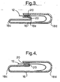
- FIG. 3 A schematic cross-section showing the sealed enclosure of Figure 1d is shown in Figure 3 .
- the position of the fold line 18a is not entirely critical and may be positioned slightly away from the sealing strip 20 along the respective edge of the sheet.
- the sealing strips 20 are arranged on opposite sides of the laminate sheet 16 so that only two fold lines are required to form a sealed seam along the surface of one-side-of the envelope enclosure.
- the end of the sheet opposite that comprising the overlying fibre sections 12a, 12b is folded along the fold line 18c by approximately 180° to overlie the splitters 10 and part of the fibres and support 14.
- the overlying fibres in the region between the fold line 18d and the sealing strip 20 at the other end of the sheet are then folded independently of the sheet to overlie the sealing strip 20 on the folded side of the sheet.
- the other end of the sheet is then folded along the fold line 18d to enclose the bent fibre sections.
- the sealing strips 20 are then brought into engagement with sections of the ingoing and outgoing fibres arranged between the strips such that they are sealingly enclosed by the application of heat and/or pressure to the sealing strips as previously described. It will be understood in this arrangement the enclosed components and fibres can be protected from the effects of the applied pressure and heat by the provision of a suitable support on the interior side of the envelope to prevent damage to the components during sealing. As in the previously described embodiment the sides of the envelope can there be sealed to provide a fully sealed enclosure containing optical components.
- Figure 3 shows a schematic cross-section of the sealed enclosure of Figure 1d with the sealing strips positioned on the same sides of the laminar sheet.
- Figure 4 is a similar cross-section view to that of Figure 3 , but of the sealed enclose of Figure 2d with the sealing strips positioned on opposite sides of the laminar sheet such that the sheet is only folded along two fold lines to form the enclosure.
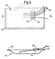
- Figure 5 shows in plan and in cross-section a plastics sheet which has been folded to form an enclosure 30 around an optical component (not shown) and has been sealed around the superposed sheet edges 32.
- Optical fibres 40 pass to and from the optical component inside the enclosure through an opening or window 34, which is sealed by an adhesive patch 3 6 of plastics film to provide the aforementioned patch-and-window seal.
- The-optical fibres are thus sealed between the exterior surface of the enclosure and the overlying portion of the patch.
- the enclosure resembles a polymer film envelope, but it will be understood that the patch-and-window seal technique could also be applied to enclosures comprising a box or tray closed by a plastics film, or to enclosure boxex made of metal or other relatively inflexible material.
- the patch may be made of and adhered by any appropriate materials, plastics films with pressure-sensitive or contact adhesives being convenient in practice.
Abstract
Description
- The present invention relates to optical fibre sealing. More in particular, the present invention relates to a method of and a device for sealingly enclosing a space into which one or more optical fibres are fed.
- It is well known that moisture has adverse effects on the properties of optical components. The split ratio of optical splitters, for example, may be influenced by the presence of moisture, and in optical connectors moisture may lead to increased losses. The sealing of optical components against moisture and other environmental influences, in other words environmental sealing, is therefore highly desirable.
- It has been proposed to environmentally seal individual optical components. This is, however, expensive and not always effective.
- In the case of electrical components it is known to seal an entire circuit by enclosing it in a flexible, moisture-resistant bag.
WO 94/18815 (Ericsson -
US-A-6 161 688 discloses an arrangement to provide electrical and/or optical components in a gas-tight packaging which includes a film-type wrapping that covers the electrical and/or optical components. Optical fiber cables as well as an electrical ribbon cable are routed through a weld. -
US-A-4 954 670 discloses a telecommunication splice case comprising a flexible sheet that can be wrapped around the splice and optionally further surrounded by a rigid casing. The sheet has a heat-activatable sealing material at its edge. - Although such an arrangement may be effective for sealing electronic circuits, it is less suitable for optical components or circuits. The applicant has found that optical fibres, unlike electrical conductors such as copper wires, should not be passed through the joint region of the laminate without additional measures. Copper wires (or other electrical conductors) may be bent under almost any angle without affecting their conductive properties. Optical fibres however, while being more flexible than copper wires, should not be bent under the minimum bending radius at which light losses occur (usually approximately 3cm), and certainly not under the minimum bending radius at which they suffer permanent damage. In addition, optical fibres are made of glass which has different sealing properties to metal.
- The applicant's earlier
GB patent application No. 0110366.2 - One disadvantage associated with this method of sealing is that the fibre or fibres are fed into the enclosed space along an edge of the container. The fibre or fibres extend substantially perpendicular with respect to the longitudinal direction of the sealed edge such that be fibres extend perpendicularly from and with respect to the sealed edge of the enclosure. This can be particularly disadvantageous in applications where there is a requirement to route the fibre back over the surface of the enclosure, for example when storing the enclosure and fibre ends in a fibre optic organiser tray or in a tray type container closed by a closure member in the form of an organiser tray, since the fibre must have a minimum bend radius which results in the fibre extending beyond the edges of the enclosure.
- There is a requirement therefore for a method of sealingly enclosing a space into which at least one optical fibre is fed which avoids the problem of the fibre exiting a sealed edge of a sealed enclosure, and a further requirement for a more compact enclosure where the fibre ends can be stored on the surface of the enclosure without extending beyond the edges thereof.
- According to a first aspect of the invention there is a method of sealingly enclosing a space into which at least one optical fibre is fed; the method comprising the steps of: (a) providing at least one optical component connected to optical fibre(s); (b) providing a flexible protective sheet having a pair of sealing strips at or towards opposite ends thereof; (c) arranging the said optical component(s) on the said sheet; (d) folding the said ends of the sheet over the said optical component to provide an envelope surrounding the said component(s) with the said seating strips arranged in overlapping engagement on one side of the envelope with the optical fibre(s) being fed into the interior of the said envelope between the sealing strips or through an aperture in a wall of the enclosure, which aperture is covered by an adherent patch or flap with the said fibre sealed between the patch or flap and a portion of the enclosure wall; (e) applying heat and/or pressure to the said sealing strips so as to provide a sealed seam along one side of the envelope or between the said patch or flap and the enclosure wall sealingly enclosing the fibre(s); and (f) sealing the sides of the envelope to provide a sealed enclosure, characterised in that the said sheet is folded such that the said seam is positioned substantially towards the centre of the said side surface of the envelope or towards one folded side edge thereof such that the side surface of the envelope over which the fibre(s) is/are fed into the envelope is of sufficient shape and size to accommodate the minimum bend radius of the overlying fibre(s).
- The term "side is used herein to refer to the two main surfaces of the sheet from which the enclosure envelope is formed, and to refer to the two main external surfaces of relatively flat envelope formed from the sheet bearing in mind that at some stages of its formation the envelope may not be truly flat, but the surfaces in question can still notionally be identified
- By folding the ends of the sheet such that the sealing strips are arranged in overlapping engagement on one side of the envelope the optical fibres can be readily fed into the interior of the envelope between the sealing strips on the side of the envelope and bent on that said of the envelope without extending beyond the envelope edges. This is particularly advantageous where thee is a requirement to loop fibre ends for storage on one side of the envelope for subsequent connection to other components or to route the fibres over one side of the envelope for connection with other components, for example for connection with other components in as optical circuit organiser tray.
- Preferably the sealing strips are provided on opposite sides of the sheet, and the end of the sheet are folded over the components along substantially parallel respective fold lines. In this way it is possible to form the envelope by folding the sheet along two parallel fold lines. By having the sealing strips on opposite sides of the sheet before folding the ends can be brought together in an overlapping arrangement with the sheet ends pointing in opposite directions to provide a sealed seam on one side of the envelope.
- In an alternative embodiment, the said sealing strips are provided on the same side of the said sheet, and the ends of the sheet are folded along substantially parallel fold lines and brought together to form an overlapping apex butt joint with the sheet ends pointing in the same direction, and folding the said apex substantially flat against the said surface. In this arrangement heat and/or pressure can be applied to the ends of the sheet forming the apex in such a way that the application of pressure and/or heat to the component in the envelope can be avoided. By further folding the sheet along both its edges containing the sealing strips it is possible for the sealing strips to be positioned on the same side of the sheet before folding so that pressure can be applied to the overlapping sealing strips in a plane substantially perpendicular to the plane of the envelope.
- Preferably, the said fibre(s) is/are arranged on the said sheet with bends in the fibre and a straight section between the bends, and the said sheet is folded at a first end along a fold line coincident with the straight section(s) of fibre only. In this way the lengths of fibre that are enclosed by the seal can be turned through an angle of 180° or so when the end of the sheet is folded along the fold line coincident with the straight section of fibres. This rotation of the fibres is accommodated by twisting of the fibres along the straight section such that the straight section of fibre behaves as a hinge.
- In preferred embodiments the fibre(s) is/are arranged with a 90° bend in the region between the seam and the fold line at the said first end. This readily permits the fibres to be arranged perpendicularly with respect to the sealing strips as they are fed into the enclosure on the side of the envelope.
- Preferably the said sheet is folded such that the said seam is positioned substantially towards the centre ofthe said side surface of the envelope or towards one folded side edge thereof such that the side surface of the envelope over which the fibre(s) is/are fed into the envelope is of sufficient shape and size to accommodate the minimum bend radius of the overlying fibre(s). This is particularly important where the fibre(s) is/are to be routed over the surface on the side of the envelope where they are fed into the envelope, for example in applications where it is desirable to locate sealed optical components in an optical organiser tray or in a tray type container closed by an organiser tray with fibres fed into the enclosure connecting the component(s) for optical connection with other components on the exterior of the enclosure.
- Preferably the said area is of sufficient shape and size to accommodate loops of fibre(s). This is particularly advantageous where is desirable to provide lengths of free fibre for connecting the enclosed component to other optical components.
- In preferred embodiments the said sheet is folded such that the distance between the seam and the respective fold line of the sheet towards which the fibres are fed is sufficient to accommodate the minimum bend radius of the fibre(s). This readily enables the fibre to be bent through an angle of 90° in the region between the seam and the fold line at the aforementioned first end of the envelope. In this way the fibre can be routed from the straight section to the sealed seam so that it is aligned perpendicularly with the sealing strips where it is fed into the enclosure.
- In preferred embodiments the sheet comprises a laminate, and preferably the laminate comprises a moisture resistant layer in combination with the sealed seam. The moisture resistant layer can provide a substantially moisture resistant enclosure for enclosing the optical component. It is preferable that the moisture resistant layer is provided by a layer of aluminium. Preferably the said component(s) are arranged on a support and the fibre(s) is/are routed in accordance with a predetermined circuit configuration with fibre end(s) fed through the envelope for optical connection with other components. This allows for prefabrication of the optical component and fibres which allows for automation of the circuit assemble, and quick and simple installation within the enclosure.
- In preferred embodiments the fibre(s) is/are fixed with respect to the said support.
- In another aspect the invention further provides an enclosure as claimed in Claim 13 wherein the said fibre is/are arranged in the container with bends in the fibre and a straight section between the bends, and a folded edge of the container is coincident with the said straight section of fibre.
- A further variation, applicable to any arrangement where optical components are sealed in an enclosure, preferably at least partly sealed by a flexible sheet, involves the optical fibres entering and/or leaving the enclosure through a window or aperture having an adherent patch or flap with the fibres sealed between the patch and a portion of the enclosure wall. Preferably, the enclosure consists of or is sealed by a polymeric film and the patch is made of polymeric film, preferably the same as that of the enclosure seal.
- Various embodiments of the invention will now be more particularly described, by way of example only, with reference to the accompanying drawings, in which:
-
Figures 1a to 1d are perspective views showing an enclosure for an optical component at various stages of production; -
Figures 2a to 2d are perspective views similar to those ofFigures 1a to 1d showing the various stages of producing an enclosure according to a different arrangement toFigures 1a to 1d ; -
Figure 3 is a cross-section view of the enclosureFigure 1d ; -
Figure 4 is a cross-section view of the enclosure ofFigure 2d ; and -
Figure 5 shows schematically the aforementioned patch-and-window seal. - Referring to
Figure 1 , a sealed enclosure for an optical component or components into which at least one optical fibre is fed is produced according to a first embodiment of the invention with reference toFigures 1 a to 1 d. InFigure 1 a an optical component comprising an array ofsplitters 10 and connectedoptical fibres 12 is mounted on a base plate support 14 with in-goingfibres 12a andoutgoing fibres 12b arranged- in mirrored-substantially S-shaped routes withstraight sections 12c extending substantially parallel to thesplitters 10 at the opposite end ofthe support 14. The arrangement of the optical component, fibres and support may be as described in the applicant's earlierGB patent application number 0129906.4 Figure 1a the optical component assembly is arranged on aflexible laminate sheet 16. The laminate sheet includes a moisture resistant barrier layer which is preferably made of aluminium. The laminate may be of the type used in Raychem's TDUX(TM) products, as disclosed inEP 0579641 and other patents. When properly sealed, such a laminate has extremely low water vapour transmission rate (WVTR). - The
sheet 16 is provided with fourparallel fold lines optical splitters 10 and straight lengths ofoptical fibre 12c. The first pair offold lines fold lines Figure 1a ) is provided with a pair of sealingstrips 20 in the region between thefold lines - In the arrangement of
Figure 1a the in andoutgoing fibres fold lines fold line 18d along thesection 12c and are then routed through a 180° bend where they connect with a respective end of arespective splitter 10. In thesection 12c the fibres are secured to the support 14 by adhesive or other means. - In the position of
Figure 1a the in and outgoing fibres between thefold lines straight section 12c as shown infigure 1d . The straight sections offibre 12c are held in torsion when in the position ofFigure 1a . - The optical components and fibres are enclosed within an envelope formed by folding and sealing the laminar sheet in accordance with the steps shown in
Figures 1b to 1d . InFigure 1b thelaminar sheet 16 is first folded along itsfold lines respective fold lines outgoing fibres Figure 1c the ends of the sheet are further rotated about theirrespective fold lines fold lines fold lines fold lines Figure 1c the sealing strips are arranged in a plane substantially perpendicular to the plane of the central part ofthe sheet and are positioned above the optical components within the envelope being formed. In this position heat and/or pressure, preferably both, is applied to the sealing strips causing the strips to change shape and to sealingly surround the fibres as described in the applicant's earlierGB patent application number 0110366.2 - When sealing of the apex seam is completed the sealed seam is rotated about the
fold lines Figure 1d . In this position the in andoutgoing fibres fold lines Figure 1a lie substantially flat within the enclosure with the sections of fibre on the other side of the seal extending flat along the surface on the side of the envelope having the fibre seam seal. The envelope is then sealed along its open side edges by the application of heat and/or pressure to seal the enclosed space within the envelope containing the optical circuit and sections of fibre. - A schematic cross-section showing the sealed enclosure of
Figure 1d is shown inFigure 3 . InFigure 3 it can be seen that the position of thefold line 18a is not entirely critical and may be positioned slightly away from the sealingstrip 20 along the respective edge of the sheet. - Referring now
Figure 2a to 2d , in another arrangement the sealing strips 20 are arranged on opposite sides of thelaminate sheet 16 so that only two fold lines are required to form a sealed seam along the surface of one-side-of the envelope enclosure. In the method ofFigures 2a to 2d the end of the sheet opposite that comprising the overlyingfibre sections fold line 18c by approximately 180° to overlie thesplitters 10 and part of the fibres and support 14. The overlying fibres in the region between thefold line 18d and the sealingstrip 20 at the other end of the sheet are then folded independently of the sheet to overlie the sealingstrip 20 on the folded side of the sheet. The other end of the sheet is then folded along thefold line 18d to enclose the bent fibre sections. The sealing strips 20 are then brought into engagement with sections of the ingoing and outgoing fibres arranged between the strips such that they are sealingly enclosed by the application of heat and/or pressure to the sealing strips as previously described. It will be understood in this arrangement the enclosed components and fibres can be protected from the effects of the applied pressure and heat by the provision of a suitable support on the interior side of the envelope to prevent damage to the components during sealing. As in the previously described embodiment the sides of the envelope can there be sealed to provide a fully sealed enclosure containing optical components. -
Figure 3 shows a schematic cross-section of the sealed enclosure ofFigure 1d with the sealing strips positioned on the same sides of the laminar sheet. -
Figure 4 is a similar cross-section view to that ofFigure 3 , but of the sealed enclose ofFigure 2d with the sealing strips positioned on opposite sides of the laminar sheet such that the sheet is only folded along two fold lines to form the enclosure. -
Figure 5 shows in plan and in cross-section a plastics sheet which has been folded to form anenclosure 30 around an optical component (not shown) and has been sealed around the superposed sheet edges 32.Optical fibres 40 pass to and from the optical component inside the enclosure through an opening orwindow 34, which is sealed by an adhesive patch 3 6 of plastics film to provide the aforementioned patch-and-window seal. The-optical fibres are thus sealed between the exterior surface of the enclosure and the overlying portion of the patch. In this example, the enclosure resembles a polymer film envelope, but it will be understood that the patch-and-window seal technique could also be applied to enclosures comprising a box or tray closed by a plastics film, or to enclosure boxex made of metal or other relatively inflexible material. The patch may be made of and adhered by any appropriate materials, plastics films with pressure-sensitive or contact adhesives being convenient in practice. - Although the invention has been described with reference to the embodiments shown in the accompanying drawings it is to be understood that the invention is not limited to those precise embodiments and that various changes and modifications may be effected without further inventive skill and effort.
Claims (16)
- A method of sealingly enclosing a space into which at least one optical fibre is fed; the method comprising the steps of: (a) providing at least one optical component connected to optical fibre(s); (b) providing a flexible protective sheet having a pair of sealing strips at or towards opposite ends thereof; (c) arranging the said optical component(s) on the said sheet; (d) folding the said ends of the sheet over the said optical component to provide an envelope surrounding the said component(s) with the said sealing strips arranged in overlapping engagement on one side of the envelope with the optical fibre(s) being fed into the interior of the said envelope between the sealing strips or through an aperture in a wall of the enclosure, which aperture is covered by an adherent patch or flap with the said fibre sealed between the patch or flap and a portion of the enclosure wall; (e) applying heat and/or pressure to the said sealing strips or to the said patch or flap so as to provide a sealed seam along one side of the envelope or between the said patch or flap and the enclosure wall sealingly enclosing the fibre(s); and (f) sealing the sides of the envelope to provide a sealed enclosure, characterised in that the said sheet is folded such that the said seam is positioned substantially towards the centre of the said side surface of the envelope or towards one folded side edge thereof such that the side surface of the envelope over which the fibre(s) is/are fed into the envelope is of sufficient shape and size to accommodate the minimum bend radius of the overlying fibre(s).
- A method as claimed in Claim 1 wherein the said sealing strips are provided on opposite sides of the said sheet, and the ends of the sheet are folded over the said component(s) along substantially parallel respective fold lines.
- A method as claimed in Claim 1 wherein the sealing strips are provided on the same side of the said sheet, and the ends of the sheet are folded along substantially parallel fold lines to form an overlapping apex, and folding the said apex substantially flat against the said surface.
- A method as claimed in any preceding claim wherein the said fibre(s) is/are arranged on the said sheet with bends in the fibre and a straight section between the bends, and the said sheet is folded at a first end along a fold line coincident with the straight section(s) of fibre only.
- A method as claimed in Claim 4 wherein the fibre(s) is/are arranged with a 90 degree bend in the region between the seam and the fold line at the said first end.
- A method as claimed in Claim 1 wherein the said area is of sufficient shape and size to accommodate loops of fibre(s).
- A method as claimed in any of Claims 5 to 6 wherein the said sheet is folded such that the distance between the seam and the respective fold line of the sheet towards which the fibres are fed is sufficient to accommodate the minimum bend radius of the fibre(s).
- A method as claimed in any preceding claim wherein the sheet comprises a laminate.
- A method as claimed in Claim 8 wherein the laminate comprises a moisture resistant layer.
- A method as claimed in Claim 9 wherein the said moisture resistant layer comprises aluminium.
- A method as claimed in any preceding claim wherein the said componet(s) are arranged on a support and the fibre(s) is/are routed in accordance with a predetermined circuit configuration with fibre end(s) fed through the envelope for optical connection with other components.
- A method as claimed in Claim 12 wherein the fibre(s) is/are fixed with respect to the said support.
- An enclosure enclosing at least one optical component and into which at least one optical fibre is fed; the said enclosure comprising a flexible bag-like container of substantially moisture resistant maternal enclosing the said component and portions of at least one optical fibre leading from the said component, wherein the container has a substantially moisture resistant seam seal on one side of the container through which the said fibre is fed, or an aperture in a wall of the enclosure, which aperture is covered by an adherent patch or flap with the fibres sealed between the patch or flap and a portion of the enclosure wall, characterised in that the said sheet is folded such that the said seam or the said aperture is positioned substantially towards the centre of the said side surface of the envelope or towards one folded side edge thereof such that the side surface of the envelope over which the fibre(s) is/are fed into the envelope is of sufficient shape and size to accommodate the minimum bend radius of the overlying fibre(s).
- An enclosure as claimed in Claim 13 wherein the said fibre is/are arranged in the container with bends in the fibre and a straight section between the bends, and a folded edge of the container is coincident with the said straight section of fibre.
- An enclosure as claimed in Claim 13 or Claim 14, which enclosure is of a size and shape for fitting into an optical fibre organiser tray.
- An enclosure according to any of Claims 13 to 15 fitted within a fibre optic organiser tray.
Applications Claiming Priority (3)
| Application Number | Priority Date | Filing Date | Title |
|---|---|---|---|
| GB0211517 | 2002-05-20 | ||
| GBGB0211517.8A GB0211517D0 (en) | 2002-05-20 | 2002-05-20 | Optical fibre sealing |
| PCT/GB2003/001955 WO2003098306A1 (en) | 2002-05-20 | 2003-05-07 | Envelope for optical fibres |
Publications (2)
| Publication Number | Publication Date |
|---|---|
| EP1506444A1 EP1506444A1 (en) | 2005-02-16 |
| EP1506444B1 true EP1506444B1 (en) | 2008-12-17 |
Family
ID=9937000
Family Applications (1)
| Application Number | Title | Priority Date | Filing Date |
|---|---|---|---|
| EP03727642A Expired - Lifetime EP1506444B1 (en) | 2002-05-20 | 2003-05-07 | Envelope for optical fibres |
Country Status (10)
| Country | Link |
|---|---|
| US (2) | US7215865B2 (en) |
| EP (1) | EP1506444B1 (en) |
| KR (1) | KR100984914B1 (en) |
| AT (1) | ATE418083T1 (en) |
| AU (1) | AU2003233880B2 (en) |
| DE (1) | DE60325349D1 (en) |
| DK (1) | DK1506444T3 (en) |
| ES (1) | ES2316753T3 (en) |
| GB (1) | GB0211517D0 (en) |
| WO (1) | WO2003098306A1 (en) |
Families Citing this family (30)
| Publication number | Priority date | Publication date | Assignee | Title |
|---|---|---|---|---|
| GB0401998D0 (en) * | 2004-01-30 | 2004-03-03 | Tyco Electronics Raychem Nv | Optical device |
| US20060233507A1 (en) * | 2005-04-14 | 2006-10-19 | Elli Makrides-Saravanos | Methods and apparatus for splitter modules and splitter module housings |
| US7340145B2 (en) | 2005-10-24 | 2008-03-04 | Tyco Electronics Corporation | Fiber optic splice storage apparatus and methods for using the same |
| US7307219B1 (en) | 2006-06-07 | 2007-12-11 | 3M Innovative Properties Company | Closure housing for sealing |
| US7531748B2 (en) * | 2006-06-07 | 2009-05-12 | 3M Innovative Properties Company | Sealing apparatus |
| US7304244B1 (en) | 2006-06-07 | 2007-12-04 | 3M Innovative Properties Company | Method of making closure housing for sealing |
| US7936960B2 (en) * | 2006-11-09 | 2011-05-03 | Corning Cable Systems Llc | Optical fiber slack storage for splice trays and splice assemblies |
| US7822310B2 (en) * | 2007-02-28 | 2010-10-26 | Corning Cable Systems Llc | Fiber optic splice trays |
| US8798427B2 (en) | 2007-09-05 | 2014-08-05 | Corning Cable Systems Llc | Fiber optic terminal assembly |
| GB0812271D0 (en) * | 2008-07-04 | 2008-08-13 | Tyco Electronics Raychem Nv | Optical comonent organiser |
| CN102209921B (en) | 2008-10-09 | 2015-11-25 | 康宁光缆系统有限公司 | There is the fibre-optic terminus supported from the adapter panel of the input and output optical fiber of optical splitters |
| US8879882B2 (en) | 2008-10-27 | 2014-11-04 | Corning Cable Systems Llc | Variably configurable and modular local convergence point |
| EP2237091A1 (en) | 2009-03-31 | 2010-10-06 | Corning Cable Systems LLC | Removably mountable fiber optic terminal |
| US8467651B2 (en) * | 2009-09-30 | 2013-06-18 | Ccs Technology Inc. | Fiber optic terminals configured to dispose a fiber optic connection panel(s) within an optical fiber perimeter and related methods |
| US9547144B2 (en) | 2010-03-16 | 2017-01-17 | Corning Optical Communications LLC | Fiber optic distribution network for multiple dwelling units |
| US8792767B2 (en) | 2010-04-16 | 2014-07-29 | Ccs Technology, Inc. | Distribution device |
| EP2397879B1 (en) | 2010-06-15 | 2017-04-26 | CommScope Connectivity Belgium BVBA | Organizer for an optical fibre cable and method of providing a splice for an optical fibre cable |
| US9547145B2 (en) | 2010-10-19 | 2017-01-17 | Corning Optical Communications LLC | Local convergence point for multiple dwelling unit fiber optic distribution network |
| US9219546B2 (en) | 2011-12-12 | 2015-12-22 | Corning Optical Communications LLC | Extremely high frequency (EHF) distributed antenna systems, and related components and methods |
| US10110307B2 (en) | 2012-03-02 | 2018-10-23 | Corning Optical Communications LLC | Optical network units (ONUs) for high bandwidth connectivity, and related components and methods |
| US9004778B2 (en) | 2012-06-29 | 2015-04-14 | Corning Cable Systems Llc | Indexable optical fiber connectors and optical fiber connector arrays |
| US9049500B2 (en) | 2012-08-31 | 2015-06-02 | Corning Cable Systems Llc | Fiber optic terminals, systems, and methods for network service management |
| US8909019B2 (en) | 2012-10-11 | 2014-12-09 | Ccs Technology, Inc. | System comprising a plurality of distribution devices and distribution device |
| WO2014189731A1 (en) * | 2013-05-21 | 2014-11-27 | Corning Optical Communications LLC | Optical cable splice cassettes with slack covers |
| DE102013012609A1 (en) * | 2013-07-26 | 2015-01-29 | Carl Zeiss Microscopy Gmbh | Opto-electronic detector, in particular for high-resolution light scanning microscopes |
| WO2017121778A1 (en) * | 2016-01-12 | 2017-07-20 | CommScope Connectivity Belgium BVBA | Cable management arrangement |
| US10746949B2 (en) | 2016-12-02 | 2020-08-18 | CommScope Connectivity Belgium BVBA | Optical fiber management systems; and methods |
| US11397295B2 (en) * | 2018-04-06 | 2022-07-26 | Commscope Technologies Llc | Flexible organizer and self-supporting unit |
| JP2022527890A (en) | 2019-03-21 | 2022-06-07 | コムスコープ テクノロジーズ リミティド ライアビリティ カンパニー | Fusion splice fiber optic cable assembly and breakout kit |
| JP6812515B1 (en) * | 2019-08-08 | 2021-01-13 | Nttエレクトロニクス株式会社 | Fiber optic packaging and optical modules |
Family Cites Families (15)
| Publication number | Priority date | Publication date | Assignee | Title |
|---|---|---|---|---|
| SE424924B (en) * | 1980-12-19 | 1982-08-16 | Ericsson Telefon Ab L M | DISTRIBUTION OF CUTTING BOXES CONTAINS OPTICAL CABLE |
| US4498732A (en) * | 1982-01-15 | 1985-02-12 | Raychem Corporation | Fiber optic splice organizer |
| US4468089A (en) * | 1982-07-09 | 1984-08-28 | Gk Technologies, Inc. | Flat cable of assembled modules and method of manufacture |
| GB8604501D0 (en) * | 1986-02-24 | 1986-04-03 | Raychem Sa Nv | Cable splice case |
| US4849580A (en) * | 1988-02-11 | 1989-07-18 | Minnesota Mining And Manufacturing Company | Environmental protection closure for wire splices; and method |
| GB9218755D0 (en) | 1992-09-04 | 1992-10-21 | Raychem Sa Nv | Environmental sealing |
| US5527989A (en) | 1993-02-11 | 1996-06-18 | Telefonaktiebolaget Lm Ericsson | Flexible device for encapsulating electronic components |
| DE19634523B4 (en) * | 1996-08-27 | 2005-02-24 | Robert Bosch Gmbh | Method for producing an arrangement of electrical and / or optoelectronic components in a gas-tight packaging and a corresponding arrangement |
| US5754724A (en) * | 1996-11-08 | 1998-05-19 | Antec Corporation | Fiber optic support apparatus |
| CA2318066C (en) * | 1998-01-22 | 2008-05-20 | Mitsubishi Cable Industries, Ltd. | Structure for retaining optical fiber |
| JP3684101B2 (en) | 1999-04-02 | 2005-08-17 | 日本電信電話株式会社 | Optical component module |
| JP2001051128A (en) | 1999-08-06 | 2001-02-23 | Mitsubishi Cable Ind Ltd | Holding structure of optical fiber |
| JP2001116950A (en) * | 1999-10-19 | 2001-04-27 | Nippon Telegr & Teleph Corp <Ntt> | Planar light wave circuit module |
| GB0110366D0 (en) * | 2001-04-27 | 2001-06-20 | Tyco Electronics Raychem Nv | Optical fibre sealing |
| EP1505765A4 (en) | 2002-06-07 | 2006-10-04 | Sony Corp | Data processing system, data processing device, data processing method, and computer program |
-
2002
- 2002-05-20 GB GBGB0211517.8A patent/GB0211517D0/en not_active Ceased
-
2003
- 2003-05-07 WO PCT/GB2003/001955 patent/WO2003098306A1/en not_active Application Discontinuation
- 2003-05-07 AT AT03727642T patent/ATE418083T1/en not_active IP Right Cessation
- 2003-05-07 US US10/514,694 patent/US7215865B2/en not_active Expired - Fee Related
- 2003-05-07 DE DE60325349T patent/DE60325349D1/en not_active Expired - Lifetime
- 2003-05-07 AU AU2003233880A patent/AU2003233880B2/en not_active Ceased
- 2003-05-07 EP EP03727642A patent/EP1506444B1/en not_active Expired - Lifetime
- 2003-05-07 DK DK03727642T patent/DK1506444T3/en active
- 2003-05-07 ES ES03727642T patent/ES2316753T3/en not_active Expired - Lifetime
- 2003-05-07 KR KR1020047018068A patent/KR100984914B1/en not_active IP Right Cessation
-
2007
- 2007-03-09 US US11/716,318 patent/US7447412B2/en not_active Expired - Fee Related
Also Published As
| Publication number | Publication date |
|---|---|
| AU2003233880B2 (en) | 2007-12-13 |
| DE60325349D1 (en) | 2009-01-29 |
| EP1506444A1 (en) | 2005-02-16 |
| US7215865B2 (en) | 2007-05-08 |
| GB0211517D0 (en) | 2002-06-26 |
| AU2003233880A1 (en) | 2003-12-02 |
| ATE418083T1 (en) | 2009-01-15 |
| US20050213918A1 (en) | 2005-09-29 |
| DK1506444T3 (en) | 2009-03-23 |
| KR20040111597A (en) | 2004-12-31 |
| WO2003098306A1 (en) | 2003-11-27 |
| US20070160339A1 (en) | 2007-07-12 |
| ES2316753T3 (en) | 2009-04-16 |
| US7447412B2 (en) | 2008-11-04 |
| KR100984914B1 (en) | 2010-10-01 |
Similar Documents
| Publication | Publication Date | Title |
|---|---|---|
| EP1506444B1 (en) | Envelope for optical fibres | |
| US7113686B2 (en) | Optical circuit enclosure | |
| US7149403B2 (en) | Optical fibre sealing assembly | |
| CN87108065A (en) | The terminal box shell of optical waveguide | |
| US5425831A (en) | Optical fiber connecting method | |
| WO1998048308A1 (en) | Fibre optic splice closure | |
| EP0742458A2 (en) | Fiber optic splice tray hinge adapter | |
| AU2002251289A1 (en) | Optical fibre sealing | |
| AU2001288500B2 (en) | Apparatus and method to vertically route and connect multiple optical fibers | |
| US6857790B2 (en) | Apparatus and method to vertically route and connect multiple optical fibers | |
| AU2001288500A1 (en) | Apparatus and method to vertically route and connect multiple optical fibers | |
| CA1149894A (en) | End seals for pre-connectorized telephone cables | |
| MXPA99009747A (en) | Fibre optic splice closure |
Legal Events
| Date | Code | Title | Description |
|---|---|---|---|
| PUAI | Public reference made under article 153(3) epc to a published international application that has entered the european phase |
Free format text: ORIGINAL CODE: 0009012 |
|
| 17P | Request for examination filed |
Effective date: 20041027 |
|
| AK | Designated contracting states |
Kind code of ref document: A1 Designated state(s): AT BE BG CH CY CZ DE DK EE ES FI FR GB GR HU IE IT LI LU MC NL PT RO SE SI SK TR |
|
| AX | Request for extension of the european patent |
Extension state: AL LT LV MK |
|
| DAX | Request for extension of the european patent (deleted) | ||
| 17Q | First examination report despatched |
Effective date: 20070510 |
|
| GRAP | Despatch of communication of intention to grant a patent |
Free format text: ORIGINAL CODE: EPIDOSNIGR1 |
|
| GRAS | Grant fee paid |
Free format text: ORIGINAL CODE: EPIDOSNIGR3 |
|
| GRAA | (expected) grant |
Free format text: ORIGINAL CODE: 0009210 |
|
| AK | Designated contracting states |
Kind code of ref document: B1 Designated state(s): AT BE BG CH CY CZ DE DK EE ES FI FR GB GR HU IE IT LI LU MC NL PT RO SE SI SK TR |
|
| REG | Reference to a national code |
Ref country code: GB Ref legal event code: FG4D |
|
| REG | Reference to a national code |
Ref country code: CH Ref legal event code: EP |
|
| REG | Reference to a national code |
Ref country code: IE Ref legal event code: FG4D |
|
| REF | Corresponds to: |
Ref document number: 60325349 Country of ref document: DE Date of ref document: 20090129 Kind code of ref document: P |
|
| REG | Reference to a national code |
Ref country code: DK Ref legal event code: T3 |
|
| REG | Reference to a national code |
Ref country code: SE Ref legal event code: TRGR |
|
| REG | Reference to a national code |
Ref country code: ES Ref legal event code: FG2A Ref document number: 2316753 Country of ref document: ES Kind code of ref document: T3 |
|
| PG25 | Lapsed in a contracting state [announced via postgrant information from national office to epo] |
Ref country code: FI Free format text: LAPSE BECAUSE OF FAILURE TO SUBMIT A TRANSLATION OF THE DESCRIPTION OR TO PAY THE FEE WITHIN THE PRESCRIBED TIME-LIMIT Effective date: 20081217 Ref country code: SI Free format text: LAPSE BECAUSE OF FAILURE TO SUBMIT A TRANSLATION OF THE DESCRIPTION OR TO PAY THE FEE WITHIN THE PRESCRIBED TIME-LIMIT Effective date: 20081217 |
|
| PG25 | Lapsed in a contracting state [announced via postgrant information from national office to epo] |
Ref country code: EE Free format text: LAPSE BECAUSE OF FAILURE TO SUBMIT A TRANSLATION OF THE DESCRIPTION OR TO PAY THE FEE WITHIN THE PRESCRIBED TIME-LIMIT Effective date: 20081217 Ref country code: BG Free format text: LAPSE BECAUSE OF FAILURE TO SUBMIT A TRANSLATION OF THE DESCRIPTION OR TO PAY THE FEE WITHIN THE PRESCRIBED TIME-LIMIT Effective date: 20090317 Ref country code: RO Free format text: LAPSE BECAUSE OF FAILURE TO SUBMIT A TRANSLATION OF THE DESCRIPTION OR TO PAY THE FEE WITHIN THE PRESCRIBED TIME-LIMIT Effective date: 20081217 |
|
| PG25 | Lapsed in a contracting state [announced via postgrant information from national office to epo] |
Ref country code: AT Free format text: LAPSE BECAUSE OF FAILURE TO SUBMIT A TRANSLATION OF THE DESCRIPTION OR TO PAY THE FEE WITHIN THE PRESCRIBED TIME-LIMIT Effective date: 20081217 Ref country code: CZ Free format text: LAPSE BECAUSE OF FAILURE TO SUBMIT A TRANSLATION OF THE DESCRIPTION OR TO PAY THE FEE WITHIN THE PRESCRIBED TIME-LIMIT Effective date: 20081217 Ref country code: PT Free format text: LAPSE BECAUSE OF FAILURE TO SUBMIT A TRANSLATION OF THE DESCRIPTION OR TO PAY THE FEE WITHIN THE PRESCRIBED TIME-LIMIT Effective date: 20090518 |
|
| PG25 | Lapsed in a contracting state [announced via postgrant information from national office to epo] |
Ref country code: SK Free format text: LAPSE BECAUSE OF FAILURE TO SUBMIT A TRANSLATION OF THE DESCRIPTION OR TO PAY THE FEE WITHIN THE PRESCRIBED TIME-LIMIT Effective date: 20081217 |
|
| PLBE | No opposition filed within time limit |
Free format text: ORIGINAL CODE: 0009261 |
|
| STAA | Information on the status of an ep patent application or granted ep patent |
Free format text: STATUS: NO OPPOSITION FILED WITHIN TIME LIMIT |
|
| 26N | No opposition filed |
Effective date: 20090918 |
|
| PG25 | Lapsed in a contracting state [announced via postgrant information from national office to epo] |
Ref country code: MC Free format text: LAPSE BECAUSE OF NON-PAYMENT OF DUE FEES Effective date: 20090531 |
|
| REG | Reference to a national code |
Ref country code: CH Ref legal event code: PL |
|
| PG25 | Lapsed in a contracting state [announced via postgrant information from national office to epo] |
Ref country code: LI Free format text: LAPSE BECAUSE OF NON-PAYMENT OF DUE FEES Effective date: 20090531 Ref country code: CH Free format text: LAPSE BECAUSE OF NON-PAYMENT OF DUE FEES Effective date: 20090531 |
|
| PG25 | Lapsed in a contracting state [announced via postgrant information from national office to epo] |
Ref country code: IE Free format text: LAPSE BECAUSE OF NON-PAYMENT OF DUE FEES Effective date: 20090507 |
|
| PG25 | Lapsed in a contracting state [announced via postgrant information from national office to epo] |
Ref country code: GR Free format text: LAPSE BECAUSE OF FAILURE TO SUBMIT A TRANSLATION OF THE DESCRIPTION OR TO PAY THE FEE WITHIN THE PRESCRIBED TIME-LIMIT Effective date: 20090318 |
|
| PG25 | Lapsed in a contracting state [announced via postgrant information from national office to epo] |
Ref country code: LU Free format text: LAPSE BECAUSE OF NON-PAYMENT OF DUE FEES Effective date: 20090507 |
|
| PG25 | Lapsed in a contracting state [announced via postgrant information from national office to epo] |
Ref country code: HU Free format text: LAPSE BECAUSE OF FAILURE TO SUBMIT A TRANSLATION OF THE DESCRIPTION OR TO PAY THE FEE WITHIN THE PRESCRIBED TIME-LIMIT Effective date: 20090618 |
|
| PG25 | Lapsed in a contracting state [announced via postgrant information from national office to epo] |
Ref country code: CY Free format text: LAPSE BECAUSE OF FAILURE TO SUBMIT A TRANSLATION OF THE DESCRIPTION OR TO PAY THE FEE WITHIN THE PRESCRIBED TIME-LIMIT Effective date: 20081217 |
|
| PGFP | Annual fee paid to national office [announced via postgrant information from national office to epo] |
Ref country code: DK Payment date: 20120525 Year of fee payment: 10 Ref country code: NL Payment date: 20120530 Year of fee payment: 10 Ref country code: TR Payment date: 20120427 Year of fee payment: 10 |
|
| PGFP | Annual fee paid to national office [announced via postgrant information from national office to epo] |
Ref country code: BE Payment date: 20120529 Year of fee payment: 10 Ref country code: SE Payment date: 20120529 Year of fee payment: 10 |
|
| BERE | Be: lapsed |
Owner name: TYCO ELECTRONICS RAYCHEM NV Effective date: 20130531 |
|
| REG | Reference to a national code |
Ref country code: NL Ref legal event code: V1 Effective date: 20131201 |
|
| REG | Reference to a national code |
Ref country code: SE Ref legal event code: EUG |
|
| PG25 | Lapsed in a contracting state [announced via postgrant information from national office to epo] |
Ref country code: SE Free format text: LAPSE BECAUSE OF NON-PAYMENT OF DUE FEES Effective date: 20130508 |
|
| REG | Reference to a national code |
Ref country code: DK Ref legal event code: EBP Effective date: 20130531 |
|
| PG25 | Lapsed in a contracting state [announced via postgrant information from national office to epo] |
Ref country code: BE Free format text: LAPSE BECAUSE OF NON-PAYMENT OF DUE FEES Effective date: 20130531 Ref country code: NL Free format text: LAPSE BECAUSE OF NON-PAYMENT OF DUE FEES Effective date: 20131201 |
|
| PG25 | Lapsed in a contracting state [announced via postgrant information from national office to epo] |
Ref country code: DK Free format text: LAPSE BECAUSE OF NON-PAYMENT OF DUE FEES Effective date: 20130531 |
|
| PG25 | Lapsed in a contracting state [announced via postgrant information from national office to epo] |
Ref country code: TR Free format text: LAPSE BECAUSE OF NON-PAYMENT OF DUE FEES Effective date: 20130507 |
|
| REG | Reference to a national code |
Ref country code: FR Ref legal event code: PLFP Year of fee payment: 14 |
|
| PGFP | Annual fee paid to national office [announced via postgrant information from national office to epo] |
Ref country code: DE Payment date: 20160527 Year of fee payment: 14 Ref country code: GB Payment date: 20160527 Year of fee payment: 14 Ref country code: ES Payment date: 20160526 Year of fee payment: 14 |
|
| PGFP | Annual fee paid to national office [announced via postgrant information from national office to epo] |
Ref country code: FR Payment date: 20160530 Year of fee payment: 14 Ref country code: IT Payment date: 20160520 Year of fee payment: 14 |
|
| REG | Reference to a national code |
Ref country code: DE Ref legal event code: R119 Ref document number: 60325349 Country of ref document: DE |
|
| GBPC | Gb: european patent ceased through non-payment of renewal fee |
Effective date: 20170507 |
|
| REG | Reference to a national code |
Ref country code: FR Ref legal event code: ST Effective date: 20180131 |
|
| PG25 | Lapsed in a contracting state [announced via postgrant information from national office to epo] |
Ref country code: DE Free format text: LAPSE BECAUSE OF NON-PAYMENT OF DUE FEES Effective date: 20171201 Ref country code: GB Free format text: LAPSE BECAUSE OF NON-PAYMENT OF DUE FEES Effective date: 20170507 |
|
| PG25 | Lapsed in a contracting state [announced via postgrant information from national office to epo] |
Ref country code: FR Free format text: LAPSE BECAUSE OF NON-PAYMENT OF DUE FEES Effective date: 20170531 Ref country code: IT Free format text: LAPSE BECAUSE OF NON-PAYMENT OF DUE FEES Effective date: 20170507 |
|
| REG | Reference to a national code |
Ref country code: ES Ref legal event code: FD2A Effective date: 20180626 |
|
| PG25 | Lapsed in a contracting state [announced via postgrant information from national office to epo] |
Ref country code: ES Free format text: LAPSE BECAUSE OF NON-PAYMENT OF DUE FEES Effective date: 20170508 |