WO2021024774A1 - Dispositif d'alimentation électrique, véhicule électrique comprenant ledit dispositif d'alimentation électrique et dispositif de stockage d'énergie - Google Patents
Dispositif d'alimentation électrique, véhicule électrique comprenant ledit dispositif d'alimentation électrique et dispositif de stockage d'énergie Download PDFInfo
- Publication number
- WO2021024774A1 WO2021024774A1 PCT/JP2020/028027 JP2020028027W WO2021024774A1 WO 2021024774 A1 WO2021024774 A1 WO 2021024774A1 JP 2020028027 W JP2020028027 W JP 2020028027W WO 2021024774 A1 WO2021024774 A1 WO 2021024774A1
- Authority
- WO
- WIPO (PCT)
- Prior art keywords
- power supply
- supply device
- intermediate plate
- plate
- metal collar
- Prior art date
Links
Images


Classifications
-
- B—PERFORMING OPERATIONS; TRANSPORTING
- B60—VEHICLES IN GENERAL
- B60L—PROPULSION OF ELECTRICALLY-PROPELLED VEHICLES; SUPPLYING ELECTRIC POWER FOR AUXILIARY EQUIPMENT OF ELECTRICALLY-PROPELLED VEHICLES; ELECTRODYNAMIC BRAKE SYSTEMS FOR VEHICLES IN GENERAL; MAGNETIC SUSPENSION OR LEVITATION FOR VEHICLES; MONITORING OPERATING VARIABLES OF ELECTRICALLY-PROPELLED VEHICLES; ELECTRIC SAFETY DEVICES FOR ELECTRICALLY-PROPELLED VEHICLES
- B60L50/00—Electric propulsion with power supplied within the vehicle
- B60L50/50—Electric propulsion with power supplied within the vehicle using propulsion power supplied by batteries or fuel cells
- B60L50/60—Electric propulsion with power supplied within the vehicle using propulsion power supplied by batteries or fuel cells using power supplied by batteries
- B60L50/64—Constructional details of batteries specially adapted for electric vehicles
-
- H—ELECTRICITY
- H01—ELECTRIC ELEMENTS
- H01M—PROCESSES OR MEANS, e.g. BATTERIES, FOR THE DIRECT CONVERSION OF CHEMICAL ENERGY INTO ELECTRICAL ENERGY
- H01M10/00—Secondary cells; Manufacture thereof
- H01M10/60—Heating or cooling; Temperature control
- H01M10/65—Means for temperature control structurally associated with the cells
- H01M10/653—Means for temperature control structurally associated with the cells characterised by electrically insulating or thermally conductive materials
-
- H—ELECTRICITY
- H01—ELECTRIC ELEMENTS
- H01M—PROCESSES OR MEANS, e.g. BATTERIES, FOR THE DIRECT CONVERSION OF CHEMICAL ENERGY INTO ELECTRICAL ENERGY
- H01M50/00—Constructional details or processes of manufacture of the non-active parts of electrochemical cells other than fuel cells, e.g. hybrid cells
- H01M50/20—Mountings; Secondary casings or frames; Racks, modules or packs; Suspension devices; Shock absorbers; Transport or carrying devices; Holders
- H01M50/204—Racks, modules or packs for multiple batteries or multiple cells
- H01M50/207—Racks, modules or packs for multiple batteries or multiple cells characterised by their shape
- H01M50/209—Racks, modules or packs for multiple batteries or multiple cells characterised by their shape adapted for prismatic or rectangular cells
-
- H—ELECTRICITY
- H01—ELECTRIC ELEMENTS
- H01M—PROCESSES OR MEANS, e.g. BATTERIES, FOR THE DIRECT CONVERSION OF CHEMICAL ENERGY INTO ELECTRICAL ENERGY
- H01M50/00—Constructional details or processes of manufacture of the non-active parts of electrochemical cells other than fuel cells, e.g. hybrid cells
- H01M50/20—Mountings; Secondary casings or frames; Racks, modules or packs; Suspension devices; Shock absorbers; Transport or carrying devices; Holders
- H01M50/218—Mountings; Secondary casings or frames; Racks, modules or packs; Suspension devices; Shock absorbers; Transport or carrying devices; Holders characterised by the material
- H01M50/22—Mountings; Secondary casings or frames; Racks, modules or packs; Suspension devices; Shock absorbers; Transport or carrying devices; Holders characterised by the material of the casings or racks
- H01M50/222—Inorganic material
- H01M50/224—Metals
-
- H—ELECTRICITY
- H01—ELECTRIC ELEMENTS
- H01M—PROCESSES OR MEANS, e.g. BATTERIES, FOR THE DIRECT CONVERSION OF CHEMICAL ENERGY INTO ELECTRICAL ENERGY
- H01M50/00—Constructional details or processes of manufacture of the non-active parts of electrochemical cells other than fuel cells, e.g. hybrid cells
- H01M50/20—Mountings; Secondary casings or frames; Racks, modules or packs; Suspension devices; Shock absorbers; Transport or carrying devices; Holders
- H01M50/218—Mountings; Secondary casings or frames; Racks, modules or packs; Suspension devices; Shock absorbers; Transport or carrying devices; Holders characterised by the material
- H01M50/22—Mountings; Secondary casings or frames; Racks, modules or packs; Suspension devices; Shock absorbers; Transport or carrying devices; Holders characterised by the material of the casings or racks
- H01M50/227—Organic material
-
- H—ELECTRICITY
- H01—ELECTRIC ELEMENTS
- H01M—PROCESSES OR MEANS, e.g. BATTERIES, FOR THE DIRECT CONVERSION OF CHEMICAL ENERGY INTO ELECTRICAL ENERGY
- H01M50/00—Constructional details or processes of manufacture of the non-active parts of electrochemical cells other than fuel cells, e.g. hybrid cells
- H01M50/20—Mountings; Secondary casings or frames; Racks, modules or packs; Suspension devices; Shock absorbers; Transport or carrying devices; Holders
- H01M50/233—Mountings; Secondary casings or frames; Racks, modules or packs; Suspension devices; Shock absorbers; Transport or carrying devices; Holders characterised by physical properties of casings or racks, e.g. dimensions
-
- H—ELECTRICITY
- H01—ELECTRIC ELEMENTS
- H01M—PROCESSES OR MEANS, e.g. BATTERIES, FOR THE DIRECT CONVERSION OF CHEMICAL ENERGY INTO ELECTRICAL ENERGY
- H01M50/00—Constructional details or processes of manufacture of the non-active parts of electrochemical cells other than fuel cells, e.g. hybrid cells
- H01M50/20—Mountings; Secondary casings or frames; Racks, modules or packs; Suspension devices; Shock absorbers; Transport or carrying devices; Holders
- H01M50/249—Mountings; Secondary casings or frames; Racks, modules or packs; Suspension devices; Shock absorbers; Transport or carrying devices; Holders specially adapted for aircraft or vehicles, e.g. cars or trains
-
- H—ELECTRICITY
- H01—ELECTRIC ELEMENTS
- H01M—PROCESSES OR MEANS, e.g. BATTERIES, FOR THE DIRECT CONVERSION OF CHEMICAL ENERGY INTO ELECTRICAL ENERGY
- H01M50/00—Constructional details or processes of manufacture of the non-active parts of electrochemical cells other than fuel cells, e.g. hybrid cells
- H01M50/20—Mountings; Secondary casings or frames; Racks, modules or packs; Suspension devices; Shock absorbers; Transport or carrying devices; Holders
- H01M50/262—Mountings; Secondary casings or frames; Racks, modules or packs; Suspension devices; Shock absorbers; Transport or carrying devices; Holders with fastening means, e.g. locks
- H01M50/264—Mountings; Secondary casings or frames; Racks, modules or packs; Suspension devices; Shock absorbers; Transport or carrying devices; Holders with fastening means, e.g. locks for cells or batteries, e.g. straps, tie rods or peripheral frames
-
- H—ELECTRICITY
- H01—ELECTRIC ELEMENTS
- H01M—PROCESSES OR MEANS, e.g. BATTERIES, FOR THE DIRECT CONVERSION OF CHEMICAL ENERGY INTO ELECTRICAL ENERGY
- H01M10/00—Secondary cells; Manufacture thereof
- H01M10/42—Methods or arrangements for servicing or maintenance of secondary cells or secondary half-cells
- H01M10/425—Structural combination with electronic components, e.g. electronic circuits integrated to the outside of the casing
-
- H—ELECTRICITY
- H01—ELECTRIC ELEMENTS
- H01M—PROCESSES OR MEANS, e.g. BATTERIES, FOR THE DIRECT CONVERSION OF CHEMICAL ENERGY INTO ELECTRICAL ENERGY
- H01M10/00—Secondary cells; Manufacture thereof
- H01M10/42—Methods or arrangements for servicing or maintenance of secondary cells or secondary half-cells
- H01M10/44—Methods for charging or discharging
- H01M10/441—Methods for charging or discharging for several batteries or cells simultaneously or sequentially
-
- H—ELECTRICITY
- H01—ELECTRIC ELEMENTS
- H01M—PROCESSES OR MEANS, e.g. BATTERIES, FOR THE DIRECT CONVERSION OF CHEMICAL ENERGY INTO ELECTRICAL ENERGY
- H01M2220/00—Batteries for particular applications
- H01M2220/20—Batteries in motive systems, e.g. vehicle, ship, plane
Definitions
- the present invention relates to a power supply device in which a plurality of square battery cells are stacked, an electric vehicle equipped with this power supply device, and a power storage device.
- a power supply device using a secondary battery is used as a power source for driving a vehicle.
- the end plates 904 are arranged on the end faces of the battery laminate 910 in which a plurality of battery cells 901 are laminated, and the end plates 904 are paired on the left and right.
- a configuration in which the binding bar 902 is fastened is generally adopted.
- a power supply device 900 in order to improve the output, it is possible to increase the number of battery cells 901.
- the intermediate plate can be fixed to the bind bar and the battery cell can be arranged in a fixed position, but dew condensation adhering to the surface of the metal collar provided on both sides of the intermediate plate to fix the bind bar. Water causes the insulation resistance of the device to decrease.
- the power supply device is required to maintain a high insulation resistance between the electrode terminal having a potential and the bus bar connected to the electrode terminal and the ground line, for example, several tens of M ⁇ or more. Since the metal collar is connected to the ground line via a metal bind bar or end plate, the insulation resistance between the metal collar connected to the ground line and the potential electrode terminal or bus bar should be maintained high. Is required.
- the intermediate plate that fixes the metal collar on both sides has battery cells stacked on both sides, and a bus bar is connected to the electrode terminal of this battery cell, and the electrode terminal and bus bar are arranged near the metal collar. Therefore, the dew condensation water adhering to the vicinity of the metal collar causes the metal collar to conduct to the electrode terminals and the bus bar, thereby lowering the insulation resistance.
- the present invention has been developed for the purpose of solving the above-mentioned drawbacks, and one of the purposes of the present invention is to effectively insulate a metal collar with an extremely simple structure and maintain a high insulation resistance of the apparatus. It is to provide the technology that can be done.
- the power supply device includes a battery laminate 10 in which a plurality of square battery cells 1 are laminated, an intermediate plate 3 in which the battery laminate 10 is laminated in the middle of the stacking direction, and a battery stack.
- a power supply device including a pair of end plates 4 arranged at both ends in the stacking direction of the body 10 and bind bars 2 fixed to both side surfaces of the end plate 4 and the intermediate plate 3, wherein the intermediate plate 3 is provided. It is provided with metal collars 31 provided on both sides of the above, a fixture 14 for connecting the bind bar 2 to the intermediate plate 3 via the metal collar 31, and an insulating plate 15 fixed to the side surface of the intermediate plate 3.
- the intermediate plate 3 is formed of an insulating plastic molded body 30 on both sides or as a whole, and the plastic molded body 30 is provided by integrally molding an annular rib 32 surrounding the periphery of the metal collar 31 on the side surface.
- the insulating plate 15 is fixed to the opening edge of the annular rib 32, the insulating plate 15 closes the opening of the annular rib 32, and the annular rib 32 and the insulating plate 15 insulate the outside of the metal collar 31.
- the fixture 14 penetrates the insulating plate 15 and is connected to the metal collar 31.
- the electric vehicle includes the power supply device 100, a traveling motor 93 to which power is supplied from the power supply device 100, a vehicle body 91 including the power supply device 100 and the motor 93, and a motor 93. It is equipped with wheels 97 that are driven by the vehicle and run the vehicle body 91.
- the power storage device includes the power supply device 100 and a power supply controller 88 that controls charging / discharging to the power supply device 100, and the power supply controller 88 is used to power the battery cell 1 from the outside. It enables charging and controls the battery cell 1 to be charged.
- the metal collar can be effectively insulated with a simple structure and the insulation resistance of the power supply device can be maintained high.
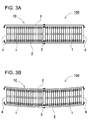
- FIG. 3A is a schematic plan view of the power supply device of FIG. 1
- FIG. 3B is a schematic plan view showing a state in which an external force is applied to the side surface of the power supply device of FIG. 3A.
- FIG. 5 is a sectional view taken along line VI-VI of the power supply device shown in FIG.
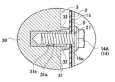
- FIG. 6 is an enlarged cross-sectional view showing a connected state of the annular rib of the intermediate plate and the insulating plate shown in FIG.
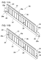
- FIG. 11A is a perspective view showing a state before bending of the protruding piece in the bind bar according to the modified example
- FIG. 11B is a perspective view showing a state in which the protruding piece of FIG. 11A is bent.
- FIG. 15 is an exploded perspective view showing a conventional power supply device.
- 16A is a schematic plan view of a power supply device without an intermediate bracket
- FIG. 16B is a schematic plan view showing a state in which an external force is applied to the side surface of the power supply device of FIG. 16A.
- FIG. 17 is a schematic plan view showing a conventional power supply device.
- the power supply device of the first embodiment of the present invention comprises a battery laminate formed by stacking a plurality of square battery cells, an intermediate plate laminated in the middle of the stacking direction of the battery laminate, and a battery laminate.
- a power supply device including a pair of end plates arranged at both ends in the stacking direction and bind bars fixed to both side surfaces of the end plate and the intermediate plate, and a metal collar provided on both sides of the intermediate plate.
- the intermediate plate is provided with a fixture for connecting the bind bar to the intermediate plate via a metal collar and an insulating plate fixed to the side surface of the intermediate plate, and the intermediate plate is made of an insulating plastic molded body on both sides or the whole.
- the plastic molded body is provided with an annular rib that surrounds the metal collar integrally molded on the side surface, and an insulating plate is fixed to the opening edge of the annular rib, so that the insulating plate is an annular rib.
- An annular rib and an insulating plate insulate the outside of the metal collar by closing the opening of the metal collar, and a fixture penetrates the insulating plate and is connected to the metal collar.
- the above power supply device has a feature that it can effectively insulate the metal collar and increase the insulation resistance of the device while having an extremely simple structure. That is, the above power supply device integrally forms an annular rib that surrounds the metal collar on the plastic molded body of the intermediate plate, and closes the opening edge of the annular rib with an insulating plate to form the annular rib. This is because the insulating plate insulates the outside of the metal collar. In particular, the above power supply device is easy because the plastic molded body forming the intermediate plate and the annular rib are integrally molded without providing a dedicated member for insulating the periphery of the metal collar.
- the annular ribs can be easily and without the addition of special parts, without the need for the process of arranging the annular ribs in the correct position with respect to the metal collar, and even in a harsh usage environment subject to vibration for a long period of time. Is placed at an accurate position around the metal collar without misalignment, and the metal collar is always insulated in an ideal state, and the insulation resistance of the device can be maintained high.
- the annular rib is closed by the insulating plate to insulate the periphery of the metal collar, the creepage distance between the electrode terminal and the bind bar and the metal collar is maintained by both the annular rib and the insulating plate. It also realizes the feature that it can be lengthened to effectively suppress the decrease in insulation resistance due to condensed water.
- the opening edge of the annular rib is brought into close contact with the inner surface of the insulating plate.
- the insulating plate is provided with a fitting groove on the inner surface for fitting the opening edge of the annular rib, and the opening edge of the annular rib is connected to the fitting groove in a fitting structure. doing.
- the metal collar is insert-molded and fixed to the plastic molded body of the intermediate plate.
- the power supply device has a female screw hole in which the fixture is a set screw and the metal collar is for screwing the set screw.
- the entire intermediate plate is made of a plastic molded body.
- the metal collar has through holes, and the fixture passes through the through holes of the metal collar formed on both sides of the intermediate plate and the intermediate plate. It is fixed to the bind bar.
- the power supply device 100 according to the embodiment of the present invention is shown in FIGS. 1 and 2.
- the power supply device 100 shown in these figures shows an example of an in-vehicle power supply device.
- the power supply device 100 is mainly mounted on an electric vehicle such as a hybrid vehicle or an electric vehicle, and is used as a power source for supplying electric power to a traveling motor of the vehicle to drive the vehicle.
- the power supply device of the present invention can be used for electric vehicles other than hybrid vehicles and electric vehicles, and can also be used for applications such as uninterruptible power supplies that require a large output other than electric vehicles.
- the power supply device 100 shown in FIGS. 1 and 2 includes a battery laminate 10 in which a plurality of battery cells 1 are laminated, an intermediate plate 3 formed by laminating in the middle of the battery laminate 10 in the stacking direction, and a battery laminate 10. It includes a pair of end plates 4 arranged at both ends in the stacking direction, and a bind bar 2 fixed to the end plates 4.
- the battery cell 1 has a plate-like outer shape whose outer shape is thinner than the width, and has a rectangular main surface, and a plurality of batteries are laminated. Further, the battery cells 1 are insulated from each other by an insulating member such as a separator 12. Further, an intermediate plate 3 is laminated in the middle of the battery laminate 10.
- the end faces on both sides of the battery laminate 10 are covered with the end plates 4.
- the pair of end plates 4 are fixed to each other by the bind bar 2, and the battery laminate 10 is sandwiched between the end plates 4.
- the outer can of the battery cell 1 has a square shape whose outer shape is thinner than the width.
- the outer can is formed in the shape of a bottomed cylinder with an opening at the top, and the opening is closed with a sealing plate.
- the electrode assembly is housed in the outer can.
- the sealing plate is provided with positive and negative electrode terminals and a gas discharge valve between the electrode terminals.
- the surface of the outer can of the battery cell is covered with an insulating film (not shown) such as a heat-shrinkable tube. Since the surface of the sealing plate is provided with electrode terminals and discharge valves, it is not covered with an insulating film and is exposed.
- the battery cells 1 are electrically connected to each other by a bus bar 13 or the like.
- the bus bar 13 is formed by bending a metal plate.
- An insulating member such as a resin separator 12 is interposed between the adjacent battery cells 1 to insulate between them.
- Battery cells whose surface is coated with an insulating film can also be laminated without a separator.
- the separator 12 is interposed between the main surfaces of the adjacent battery cells 1 facing each other to insulate them.
- the separator 12 is also arranged between the battery cells 1 and the end plate 4 at both ends, and between the battery cell 1 and the intermediate plate 3 in the middle.
- the separator 12 is made of an insulating material in the form of a thin plate or sheet.
- the separator 12 shown in the figure has a plate shape having a size substantially equal to the facing surface of the battery cell 1, and the separator 12 is laminated between the battery cells 1 adjacent to each other to insulate the adjacent battery cells 1 from each other. ing.
- a separator having a shape that forms a flow path of the cooling gas between adjacent battery cells can be used, and the cooling gas can be forcibly blown into the flow path to cool the battery cell.
- the material of the separator 12 is insulating.
- a resin such as plastic
- it can be constructed lightweight and inexpensively.
- it may be a flexible member.
- the separator 12 having no cooling gap can be made of a thin and flexible material such as a sheet. If a separator having an adhesive surface coated on one side as a sheet is used, it can be easily attached to an area requiring insulation such as a main surface or a part of a side surface of the battery cell 1.
- the sheet shape makes it easy to reduce the thickness of the separator, and it is possible to suppress an increase in the thickness and weight of the battery laminate 10.
- End plate 4 A pair of end plates 4 are arranged on both end surfaces of the battery laminate 10 in which the battery cells 1 and the separator 12 are alternately laminated, and the battery laminate 10 is fastened by the pair of end plates 4.
- the end plate 4 is made of a material that exhibits sufficient strength, for example, metal.
- the end plate may be made of resin, or the end plate made of resin may be reinforced with a member made of metal.
- the end plate 4 is composed of one metal plate.
- the bind bars 2 are arranged on both side surfaces of the battery laminate 10 in which the end plates 4 are laminated on both ends, and the ends are fixed to the pair of end plates 4 to form the battery laminate. Conclude 10.
- the bind bar 2 is formed in a plate shape extending in the battery stacking direction of the battery stack 10.
- the bind bar 2 has a flat plate-shaped fastening main surface 25 that covers the side surface of the battery laminate 10, and the first bent piece 21 and the second bent piece as bent pieces whose edges are bent. It has a piece 22, a third bent piece 23, and a fourth bent piece 24.
- the first bent piece 21 is an upper end bent piece in which one of the end edges along the longitudinal direction of the fastening main surface 25, here, the upper end side is bent.
- the second bent piece 22 is a lower end bent piece obtained by bending the other end edge of the fastening main surface 25 along the longitudinal direction, here the lower end side.
- the third bent piece 23 is an end plate fixing piece whose end edge intersecting the longitudinal direction of the fastening main surface 25, in which the front side is partially bent.
- the fourth bent piece 24 is an end plate fixing piece in which the rear side of the edge intersecting the longitudinal direction of the fastening main surface 25 is partially bent.
- a bent metal plate is preferably used.
- the bind bar 2 needs to have sufficient strength so as to hold the battery laminate 10 for a long period of time. Therefore, high-strength steel, general steel, stainless steel, aluminum alloy, magnesium alloy, etc., which are excellent in rigidity and heat conduction, or a combination thereof can be used.
- a metal plate made of Fe-based metal is used.
- the bind bar can have other shapes.
- both ends of the metal plate extended in a strip shape may be bent in a U-shape in a cross-sectional view.
- the position where the bind bar is provided can be the side surface of the battery laminate or the upper and lower surfaces.
- the structure for fixing the bind bar to the end plate is not limited to screwing, and known fixing structures such as rivets, caulking, welding, and adhesion can be appropriately used.
- an opening region 25a may be provided on the fastening main surface 25 of the bind bar 2 so that cooling gas can be blown between the battery cells 1. In the examples of FIGS.
- a plurality of opening regions 25a are provided on the fastening main surface 25 of the bind bar 2 so that the side surface of the battery cell 1 is exposed to the side surface of the battery laminate 10. Further, it is preferable that the bind bar 2 is made of metal in order to prevent the strength of the bind bar 2 from being lowered by providing the opening region 25a.
- the intermediate plate fixing portion 27 for connecting to the intermediate plate 3.
- the battery cell 1 is not located in the portion of the intermediate plate 3, there is no cooling gap for cooling the battery cell 1, and therefore it is not necessary to provide an opening region.
- by not providing the opening region or reducing the area of the opening region in the portion where the strength is required it is possible to avoid the decrease in strength and the decrease in rigidity while ensuring the cooling performance of the battery cell 1.
- the space between the bind bar 2 and the battery laminate 10 is prevented.
- the insulating material 9 is interposed between the metal bind bar 2 and the battery laminate 10.
- the insulating material 9 is made of an insulating member such as a resin sheet or paper.
- the shape of the insulating material 9 is substantially the same as that of the bind bar 2, so that the side surface of the battery laminate 10 does not come into contact with the bind bar 2.
- the opening region 9a is also opened in the insulating material 9 so as not to block the opening region 25a.
- an intermediate plate 3 is interposed in the intermediate portion of the battery laminate 10.
- the battery laminate 10 of FIGS. 1 to 4 is provided with one intermediate plate 3 in the center, it does not necessarily have to be in the center and may be provided between the battery laminates in the stacking direction. That is, the meaning of "intermediate in the stacking direction of the battery laminate” means “between the stacking directions of the battery laminate”.
- the long battery laminate may be provided with a plurality of intermediate plates in the middle.
- the intermediate plate 3 is fixed in the middle of the bind bar 2 in the longitudinal direction. Therefore, the bind bar 2 has an intermediate plate fixing portion 27 for fixing to the intermediate plate 3 in the middle in the longitudinal direction.
- the intermediate plate 3 fixes the metal collar 31 to be fixed to the intermediate plate fixing portion 27.
- the intermediate plate 3 by reinforcing the intermediate portion of the battery laminate 10 with the intermediate plate 3, there is an advantage that the rigidity can be maintained even when the number of stacked battery cells 1 increases.
- a configuration is adopted in which the end plates 904 on both end surfaces are fastened with the bind bar 902.
- 18 thin square battery cells 901 are laminated via a separator 912, end plates 904 are arranged on the end faces of the battery laminate 910, and end plates 904 on both end faces are fastened to each other with bind bars 902. doing.
- the battery cell 901 narrowly held by the bind bar 902 and the battery laminate 910 of the separator 912 are not fixed to the bind bar 902.
- the intermediate plate 3 is provided in the intermediate portion of the bind bar 2, and is further fixed to each of the pair of bind bars 2.
- the pair of bind bars 2 are fixed to each other at the intermediate portion via the intermediate plate 3.
- the effect of suppressing the variation in thickness between the battery cells by the intermediate plate 3 can be obtained. That is, as the number of stacked battery cells is increased, the variation in the thickness of each battery cell 901 is accumulated as shown in FIG. Similarly, since the separator 912 also has a manufacturing tolerance, the thickness variation is accumulated as in the case of the number of battery cells 901.
- the length of the bind bar 902 corresponds to the variation in the thickness of the battery cell 901 and the separator 912 as shown in FIG. If the length is not set, it will be difficult to maintain an appropriate holding state.
- the intermediate plate 3 in the middle as shown in FIG. 4, one surface of the intermediate plate 3 and one end plate 4, and the other surface of the intermediate plate 3 and the other end plate 4 Since the battery laminate 10 can be divided into two parts and sandwiched between the two, the number of layers of the divided battery laminates 10 can be halved, and such a cumulative error can be reduced to reduce the cumulative error in the bind bar 2. It can be easily fastened. In other words, it is possible to suppress variations in the fastening state of the bind bar 2 between the power supply devices, maintain the fastening state of each power supply device constant, and improve reliability.
- the position where the intermediate plate 3 is arranged on the bind bar 2 is preferably approximately the center in the longitudinal direction of the bind bar 2. However, it does not prevent the intermediate plate from being placed and fixed at a position slightly eccentric to either one. In particular, when the number of stacked battery cells is even, it is possible to arrange the intermediate plate in the center, but when the number is odd, it becomes difficult to arrange the intermediate plate in the middle.
- the present invention can also be preferably used in such an embodiment. Further, when a plurality of intermediate plates are provided, it is also preferable to arrange the plurality of intermediate plates at equal intervals in the longitudinal direction of the bind bar 2.
- the intermediate plate 3 is preferably made of insulating plastic.
- the intermediate plate is not entirely made of plastic.
- both side portions and upper and lower portions of the quadrangle, that is, the outer peripheral portion and both sides may be made of plastic and the other parts may be made of metal.
- This intermediate plate can be manufactured by insert molding a metal plate into plastic to insulate the surface with plastic.
- the above intermediate plate 3 can be reliably insulated from the battery cells 1 laminated on both sides.
- Examples of the resin material for forming the intermediate plate include crystalline polymer (LCP), polyphenylene sulfide (PPS), polyethersulfone (PES), polybutylene terephthalate (PBT), polyamideimide (PAI), and polyphthalamide (PPA). , Polyetheretherketone (PEEK), polycarbonate and the like can be used.
- LCP crystalline polymer
- PPS polyphenylene sulfide
- PES polyethersulfone
- PBT polybutylene terephthalate
- PAI polyamideimide
- PPA polyphthalamide
- PEEK Polyetheretherketone
- the intermediate plate 3 has metal collars 31 fixed on both sides to fix the bind bar 2.
- the metal collar 31 is preferably insert-molded and fixed to the intermediate plate 3.
- the metal collar 31 shown in the cross-sectional view of FIG. 6 is provided with a ring-shaped groove 31b on the outer peripheral surface in order to be firmly fixed to the intermediate plate 3.
- a large number of protrusions can be provided on the outer peripheral surface.
- the metal collar 31 which is insert-molded and fixed is firmly fixed to the exact position of the intermediate plate 3. However, the metal collar can be glued or press-fitted to be fixed to the intermediate plate.
- the hybrid structure in which the metal collar 31 is insert-molded and fixed to the plastic intermediate plate 3 is a fixing portion with the bind bar 2 which is required to have strength and durability while making the intermediate plate 3 lightweight and easy to mold. Is made of metal, which makes it possible to increase reliability.
- the intermediate plate 3 described above is made of plastic, and the metal collar 31 is insert-molded and fixed, but the metal collar can also be integrated with the intermediate plate. A part of this intermediate plate is made of metal and has a structure integrated with a metal collar, and the surface of the metal intermediate plate is insulated with plastic or the like.
- This intermediate plate can be realized by a structure in which the portion to be molded integrally with the metal collar is made of die-cast aluminum and the surface is insulated with plastic or the like.
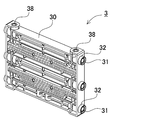
- the metal collar 31 is fixed to the intermediate plate 3 at a plurality of places on both side surfaces, and the bind bar 2 is securely fixed.
- the intermediate plates 3 of FIGS. 5 and 6 have metal collars 31 fixed at three locations, one above the other and one at the center. Although the number of metal collars 31 fixed to the intermediate plate 3 is not specified, the bind bar 2 can be securely fixed by being fixed at the top and bottom and in the middle thereof.
- the metal collar 31 protrudes from the side surface of the intermediate plate 3 and is fixed so that the tip is flat. Further, the metal collar 31 is provided with a female screw hole 31a in the central portion. A set screw 14A penetrating the bind bar 2 is screwed into the female screw hole 31a to connect the bind bar 2 to the intermediate plate 3.
- the metal collar 31 is electrically connected to the ground line via the metal bind bar 2. This is because the bind bar 2 is connected to the base on which the power supply device is installed, or to the chassis in the vehicle.
- the metal collar 31 electrically connected to the ground line is connected to the electrode terminal of the battery cell 1 or the bus bar via condensed water or the like, the insulation resistance is lowered. This is because the conductive dew condensation water electrically connects the metal collar 31 to the ground line.
- the left and right metal collars 31 are provided on both side surfaces of the intermediate plate 3 on the same straight line.
- the metal collar can also be configured to penetrate the intermediate plate, which can improve its strength.
- the intermediate plate 3 Since the power supply device 100 is used in an environment where external conditions such as temperature change, when the air in contact with the surface is cooled and becomes supersaturated, water vapor in the air is liquefied and adheres to the surface as condensed water. To do.
- the intermediate plate 3 is provided with an annular rib 32 that surrounds the metal collar 31 integrally molded on the side surface. Since the intermediate plate 3 described above is entirely made of plastic, the entire intermediate plate 3 is made of a plastic molded body 30. The annular rib 32 is integrally molded with the plastic molded body 30 to be provided.
- the metal collar 31 is arranged inside the annular rib 32, and the periphery of the metal collar 31 is insulated by the annular rib 32.
- the entire intermediate plate 3 is composed of the plastic molded body 30, but the intermediate plate does not necessarily have the entire intermediate plate as a plastic molded body.
- the core material may be a metal plate and the surface may be a plastic molded body. it can.
- This intermediate plate is manufactured in a structure in which a metal plate is insert-molded and embedded in a plastic molded body.
- the intermediate plate 3 having a part of the plastic molded body 30 is composed of at least both side portions of the plastic molded body 30 to form the annular rib 32 as an integral structure. Mold.
- the annular rib 32 is fixed so that the insulating plate 15 is in close contact with the opening edge, and the opening is closed by the insulating plate 15.
- the insulating plate 15 is pressed against the annular rib 32 by the bind bar 2 arranged on the outer surface and is in close contact with the insulating plate 15 without a gap.
- the annular rib 32 of FIG. 7 is gradually sharpened at the tip edge and crushed by the insulating plate 15 to be pressed, so that the annular rib 32 is more reliably adhered without a gap.
- the through hole 15a which is slightly smaller than the outer diameter of the set screw 14A, is widened by the set screw 14A to be inserted and comes into close contact with the surface of the set screw 14A.
- the insulating plate 15 can watertightly seal the opening of the annular rib 32 to insulate the metal collar 31 in an ideal state.
- the through hole 15a can be made larger than the outer diameter of the set screw 14A so that a gap is formed when the set screw 14A is inserted.
- the insulating plate 15 does not hermetically seal the opening of the annular rib 32, but the annular rib 32 and the insulating plate 15 cover the outside of the metal collar 31 to increase the creepage distance and suppress the decrease in insulation resistance. To do.
- a set screw 14A penetrating the intermediate plate fixing portion 27 which is a through hole provided in the bind bar 2 and the through hole 9b provided in the insulating material 9 is inserted through the through hole 15a and the metal collar 31 is inserted.
- the opening edge of the annular rib 32 is pressed into close contact with the opening of the annular rib 32 to close the opening.
- the insulating plate 15 can be mass-produced at low cost while having the optimum material and shape. Further, by using the insulating plate as a separate member, it is possible to simplify the handling and improve the manufacturing efficiency.
- the insulating plate may have an integral structure with the insulating material.
- the insulating plate is integrally manufactured as a part of an insulating material manufactured in the form of a plate or a sheet. This insulating plate is also arranged in a fixed position with respect to the side surface of the intermediate plate in a state where the insulating material is connected to the fixed position of the bind bar to close the opening of the annular rib. Further, the insulating plate can be fixed to the inner surface of the insulating material as a plurality of plate materials facing each annular rib.
- the bind bar 2 is provided with an intermediate plate fixing portion 27 for fixing to the metal collar 31 of the intermediate plate 3 in the middle in the longitudinal direction.
- the direction of the fixture 14 for fixing the intermediate plate 3 and the bind bar 2 is set to be substantially perpendicular to the main surface of the bind bar 2.
- the metal collar 31 is a metal cylinder provided with a through hole 31c, and the metal collar 31 is insert-molded into a plastic molded body 30 so as to penetrate the intermediate plate 3 in the width direction. And manufacture.
- the fixture 14 shown in FIG. 8 is composed of a bolt 14B having a threaded portion longer than the width of the intermediate plate and a nut member 14C screwed into the bolt 14B.
- the nut member 14C is attached to the tip of the intermediate plate 3 in a state where the front end of the screw portion of the bolt penetrating the metal collar 31 is projected from the opposite side surface and is penetrated through the insulating plate 15 and the bind bar 2.
- the structure is such that the bind bar 2 is fixed to both side surfaces of the intermediate plate 3 by screwing.
- the fixture penetrating the intermediate plate may be composed of a screw rod longer than the width of the intermediate plate 3 and nut members connected to both ends of the screw rod.
- a plurality of fixing structures for fixing the bind bar 2 to the intermediate plate 3 may be provided.
- a second fixing portion 28 on the fastening member side may be provided in the middle of the first bent piece 21.
- the bind bar 2 shown in FIGS. 1, 2 and 6 forms a first bent piece screw hole protruding from the center of the first bent piece 21 as the second fixing portion 28 on the fastening member side. ..
- the second fixing portion 28 on the fastening member side at the portion intersecting the intermediate plate fixing portion 27, the bind bar 2 and the intermediate plate 3 can be fixed at positions intersecting each other, which are different. A stronger fixing structure from the direction is realized.
- a second screw hole on the bracket side is opened as a second fixing portion 38 on the bracket side at a portion facing the first bent single screw hole.
- the intermediate plate 3 is also provided with a bracket-side third screw hole as a bracket-side third fixing portion 39 at a position corresponding to the fastening member-side third fixing portion 29.
- the intermediate portion is opened to reduce the amount of resin used.
- the separator having a ventilation gap is arranged on both sides of the intermediate plate, the separator is formed in a shape that matches the shape of the separator, for example, the unevenness of the cooling gap.
- the side surface of the battery cell 1 is coated with the separator 12 and joined to the intermediate plate 3.
- a separator 12 is interposed between the battery cell 1 and the intermediate plate 3.
- the separator may be omitted for the battery cell in contact with the intermediate plate.
- the above-mentioned cooling gap or the like may be formed on the surface of the intermediate plate so that the surface of the battery cell can be covered with the side surface of the intermediate plate.
- the bind bar 2 has a structure in which the end edges of the fastening main surface 25 are bent, respectively, and further bent to fix the bent pieces to each other to increase the strength. It can also be improved.
- Such an example is shown in the perspective views of FIGS. 11A and 11B as the bind bar 2B according to the modified example.
- the bind bar 2B shown in these figures has a protruding piece 26 in which the second bent piece 22 has its longitudinal end protruding from the edge of the fastening main surface 25.
- the protruding piece 26 has a protruding piece side screw hole 26a for screwing with the end plate 4.
- the third bent piece 23 and the fourth bent piece 24 have a third screw hole 23a and a fourth screw hole 24a, respectively.
- the projecting piece 26 is bent from the state of FIG. 11A so as to overlap the second bent piece 22 as shown in FIG. 11B. In this state, the protruding one-side screw hole 26a, the third screw hole 23a, and the fourth screw hole 24a are aligned, screwed into a common screw, and fixed to the end plate 4.
- the surfaces where the bind bar 2B is screwed with the end plate 4 are three-dimensionally configured by the intersecting surfaces, and a stronger fixing structure is realized.
- the above power supply device can be used as a power source for a vehicle that supplies electric power to a motor that runs an electric vehicle.
- an electric vehicle equipped with a power supply device an electric vehicle such as a hybrid vehicle or a plug-in hybrid vehicle that runs on both an engine and a motor, or an electric vehicle that runs only on a motor can be used, and is used as a power source for these vehicles.
- an electric vehicle such as a hybrid vehicle or a plug-in hybrid vehicle that runs on both an engine and a motor, or an electric vehicle that runs only on a motor can be used, and is used as a power source for these vehicles.
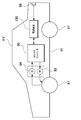
- FIG. 12 shows an example in which a power supply device is mounted on a hybrid vehicle that runs on both an engine and a motor.
- the vehicle HV equipped with the power supply device shown in this figure includes a vehicle body 91, an engine 96 for traveling the vehicle body 91, a motor 93 for traveling, and wheels driven by these engines 96 and a motor 93 for traveling. 97, a power supply device 100 for supplying electric power to the motor 93, and a generator 94 for charging the battery of the power supply device 100 are provided.
- the power supply device 100 is connected to the motor 93 and the generator 94 via the DC / AC inverter 95.
- the vehicle HV runs on both the motor 93 and the engine 96 while charging and discharging the battery of the power supply device 100.
- the motor 93 is driven to drive the vehicle in a region where the engine efficiency is low, for example, when accelerating or traveling at a low speed.
- the motor 93 is driven by being supplied with electric power from the power supply device 100.
- the generator 94 is driven by the engine 96 or by regenerative braking when braking the vehicle to charge the battery of the power supply device 100.
- the vehicle HV may be provided with a charging plug 98 for charging the power supply device 100. By connecting the charging plug 98 to an external power source, the power supply device 100 can be charged.
- FIG. 13 shows an example in which a power supply device is mounted on an electric vehicle traveling only by a motor.
- the vehicle EV equipped with the power supply device shown in this figure supplies electric power to the vehicle body 91, the motor 93 for traveling the vehicle body 91, the wheels 97 driven by the motor 93, and the motor 93.
- the power supply device 100 and the generator 94 for charging the battery of the power supply device 100 are provided.
- the power supply device 100 is connected to the motor 93 and the generator 94 via the DC / AC inverter 95.
- the motor 93 is driven by being supplied with electric power from the power supply device 100.
- the generator 94 is driven by the energy used for regenerative braking of the vehicle EV to charge the battery of the power supply device 100.
- the vehicle EV is provided with a charging plug 98, and the charging plug 98 can be connected to an external power source to charge the power supply device 100.
- the power supply device for power storage device
- the present invention does not specify the use of the power supply device as the power source of the motor for traveling the vehicle.
- the power supply device according to the embodiment can also be used as a power source for a power storage device that charges and stores a battery with electric power generated by solar power generation, wind power generation, or the like.
- FIG. 14 shows a power storage device in which the battery of the power supply device 100 is charged by the solar cell 82 to store electricity.
- the power storage device shown in FIG. 14 charges the battery of the power supply device 100 with the electric power generated by the solar cells 82 arranged on the roof or roof of a building 81 such as a house or factory.
- This power storage device uses the solar cell 82 as a power source for charging, charges the battery of the power supply device 100 with the charging circuit 83, and then supplies power to the load 86 via the DC / AC inverter 85. Therefore, this power storage device has a charge mode and a discharge mode.
- the DC / AC inverter 85 and the charging circuit 83 are connected to the power supply device 100 via the discharge switch 87 and the charging switch 84, respectively.
- the ON / OFF of the discharge switch 87 and the charge switch 84 is switched by the power controller 88 of the power storage device.
- the power controller 88 switches the charging switch 84 to ON and the discharge switch 87 to OFF to allow the charging circuit 83 to charge the power supply device 100.
- the power controller 88 turns off the charging switch 84 and turns on the discharge switch 87 to switch to the discharge mode, and the power supply device 100 Allows discharge from to load 86.
- the charge switch 84 can be turned on and the discharge switch 87 can be turned on to supply power to the load 86 and charge the power supply device 100 at the same time.
- the power supply device can also be used as a power source for a power storage device that charges and stores batteries by using midnight power at night.
- a power supply device charged with midnight power can be charged with midnight power, which is surplus power of a power plant, and output power in the daytime when the power load is large, so that the peak power in the daytime can be limited to a small value.
- the power supply can also be used as a power source for charging with both solar cell output and midnight power. This power supply device can effectively utilize both the power generated by the solar cell and the midnight power, and can efficiently store electricity while considering the weather and power consumption.
- the above-mentioned power storage devices include backup power supply devices that can be mounted in computer server racks, backup power supply devices for wireless base stations such as mobile phones, power storage power supplies for homes or factories, power supplies for street lights, etc. It can be suitably used for power storage devices combined with solar cells, backup power sources for traffic lights and traffic indicators for roads, and the like.
- the power supply device according to the present invention and the electric vehicle and power storage device provided with this power supply device are for large currents used for power supply of motors for driving electric vehicles such as hybrid vehicles, fuel cell vehicles, electric vehicles, and electric motorcycles.
- a power supply device for a plug-in type hybrid electric vehicle, a hybrid electric vehicle, an electric vehicle, or the like that can switch between an EV driving mode and a HEV driving mode can be mentioned.
- a backup power supply device that can be mounted in a computer server rack, a backup power supply device for wireless base stations such as mobile phones, a power storage device for home use and factories, a power storage device for street lights, etc. , Can also be used as appropriate for backup power supplies such as traffic lights.
Landscapes
- Chemical & Material Sciences (AREA)
- Chemical Kinetics & Catalysis (AREA)
- Electrochemistry (AREA)
- General Chemical & Material Sciences (AREA)
- Engineering & Computer Science (AREA)
- Manufacturing & Machinery (AREA)
- Inorganic Chemistry (AREA)
- Life Sciences & Earth Sciences (AREA)
- Sustainable Development (AREA)
- Sustainable Energy (AREA)
- Power Engineering (AREA)
- Transportation (AREA)
- Mechanical Engineering (AREA)
- Aviation & Aerospace Engineering (AREA)
- Battery Mounting, Suspending (AREA)
Abstract
La présente invention concerne un dispositif d'alimentation électrique permettant d'isoler efficacement un collier métallique avec une structure simple et de maintenir une résistance d'isolation élevée du dispositif, une plaque intermédiaire (3) étant stratifiée au milieu d'un stratifié de batterie de multiples cellules de batterie carrée, une paire de plaques d'extrémité étant disposées des deux extrémités de celui-ci, et des barres de liaison (2) étant fixées sur les plaques d'extrémité et la plaque intermédiaire (3) ; le dispositif d'alimentation électrique comprend des colliers métalliques (31) qui sont disposés des deux côtés de la plaque intermédiaire (3), des gabarits de fixation (14) qui relient la barre de liaison (2) à la plaque intermédiaire (3), et une plaque d'isolation (15) qui est fixée à la surface latérale de la plaque intermédiaire (3). La plaque intermédiaire (3) est constituée d'un corps en plastique moulé isolant (30), et des nervures annulaires (32) entourant les colliers métalliques (31) font partie intégrante de sa surface latérale. La plaque d'isolation (15) est fixée au bord ouvert des nervures annulaires (32), fermant l'ouverture dans les nervures annulaires (32) ; l'extérieur des colliers métalliques (31) est isolé par les nervures annulaires (32) et la plaque d'isolation (15) ; et les gabarits de fixation (14) traversent la plaque d'isolation (15) et sont reliés aux colliers métalliques (31).
Applications Claiming Priority (2)
| Application Number | Priority Date | Filing Date | Title |
|---|---|---|---|
| JP2019-143425 | 2019-08-03 | ||
| JP2019143425A JP2022133490A (ja) | 2019-08-03 | 2019-08-03 | 電源装置とこの電源装置を備える電動車両及び蓄電装置 |
Publications (1)
| Publication Number | Publication Date |
|---|---|
| WO2021024774A1 true WO2021024774A1 (fr) | 2021-02-11 |
Family
ID=74504104
Family Applications (1)
| Application Number | Title | Priority Date | Filing Date |
|---|---|---|---|
| PCT/JP2020/028027 WO2021024774A1 (fr) | 2019-08-03 | 2020-07-20 | Dispositif d'alimentation électrique, véhicule électrique comprenant ledit dispositif d'alimentation électrique et dispositif de stockage d'énergie |
Country Status (2)
| Country | Link |
|---|---|
| JP (1) | JP2022133490A (fr) |
| WO (1) | WO2021024774A1 (fr) |
Cited By (3)
| Publication number | Priority date | Publication date | Assignee | Title |
|---|---|---|---|---|
| EP4358210A1 (fr) | 2022-10-20 | 2024-04-24 | Prime Planet Energy & Solutions, Inc. | Module de batterie |
| EP4358252A1 (fr) | 2022-10-20 | 2024-04-24 | Prime Planet Energy & Solutions, Inc. | Module de batterie |
| EP4358241A1 (fr) | 2022-10-20 | 2024-04-24 | Prime Planet Energy & Solutions, Inc. | Module de batterie et son procédé de fabrication |
Citations (4)
| Publication number | Priority date | Publication date | Assignee | Title |
|---|---|---|---|---|
| WO2014034057A1 (fr) * | 2012-08-27 | 2014-03-06 | 三洋電機株式会社 | Système de batterie, véhicule électrique équipé de ce système de batterie et dispositif de stockage d'électricité |
| WO2017017913A1 (fr) * | 2015-07-30 | 2017-02-02 | 三洋電機株式会社 | Dispositif d'alimentation, et véhicule mettant en œuvre celui-ci |
| JP2017147198A (ja) * | 2016-02-19 | 2017-08-24 | 株式会社Gsユアサ | 蓄電装置、及び該蓄電装置の製造方法 |
| JP2019032997A (ja) * | 2017-08-08 | 2019-02-28 | 株式会社ブルーエナジー | 蓄電装置 |
-
2019
- 2019-08-03 JP JP2019143425A patent/JP2022133490A/ja active Pending
-
2020
- 2020-07-20 WO PCT/JP2020/028027 patent/WO2021024774A1/fr active Application Filing
Patent Citations (4)
| Publication number | Priority date | Publication date | Assignee | Title |
|---|---|---|---|---|
| WO2014034057A1 (fr) * | 2012-08-27 | 2014-03-06 | 三洋電機株式会社 | Système de batterie, véhicule électrique équipé de ce système de batterie et dispositif de stockage d'électricité |
| WO2017017913A1 (fr) * | 2015-07-30 | 2017-02-02 | 三洋電機株式会社 | Dispositif d'alimentation, et véhicule mettant en œuvre celui-ci |
| JP2017147198A (ja) * | 2016-02-19 | 2017-08-24 | 株式会社Gsユアサ | 蓄電装置、及び該蓄電装置の製造方法 |
| JP2019032997A (ja) * | 2017-08-08 | 2019-02-28 | 株式会社ブルーエナジー | 蓄電装置 |
Cited By (3)
| Publication number | Priority date | Publication date | Assignee | Title |
|---|---|---|---|---|
| EP4358210A1 (fr) | 2022-10-20 | 2024-04-24 | Prime Planet Energy & Solutions, Inc. | Module de batterie |
| EP4358252A1 (fr) | 2022-10-20 | 2024-04-24 | Prime Planet Energy & Solutions, Inc. | Module de batterie |
| EP4358241A1 (fr) | 2022-10-20 | 2024-04-24 | Prime Planet Energy & Solutions, Inc. | Module de batterie et son procédé de fabrication |
Also Published As
| Publication number | Publication date |
|---|---|
| JP2022133490A (ja) | 2022-09-14 |
Similar Documents
| Publication | Publication Date | Title |
|---|---|---|
| JP6878279B2 (ja) | 電源装置及びこれを用いた車両 | |
| WO2021024774A1 (fr) | Dispositif d'alimentation électrique, véhicule électrique comprenant ledit dispositif d'alimentation électrique et dispositif de stockage d'énergie | |
| WO2012133707A1 (fr) | Dispositif de source d'alimentation et véhicule comportant un dispositif de source d'alimentation | |
| JP6189301B2 (ja) | 電源装置及びこれを備える電動車両並びに蓄電装置 | |
| WO2012133709A1 (fr) | Dispositif de source d'alimentation, et véhicule comportant un dispositif de source d'alimentation | |
| WO2012133708A1 (fr) | Dispositif de source d'alimentation et véhicule comportant un dispositif de source d'alimentation | |
| JP2012243689A (ja) | 電源装置、電源装置を備える車両並びにバスバー | |
| WO2013161654A1 (fr) | Dispositif d'alimentation électrique, véhicule comprenant le dispositif d'alimentation électrique, et dispositif de stockage d'électricité | |
| JPWO2012057322A1 (ja) | 組電池及びこれを用いた車両 | |
| WO2021024776A1 (fr) | Dispositif d'alimentation électrique, véhicule électrique comprenant un dispositif d'alimentation électrique et dispositif de stockage d'énergie | |
| JP2012033419A (ja) | 電源装置及びこれを用いた車両、電池セル及び電池セルの製造方法 | |
| WO2013002090A1 (fr) | Dispositif d'alimentation en énergie, véhicule comprenant ce dispositif, et procédé de fabrication d'un dispositif d'alimentation en énergie | |
| JP2018060595A (ja) | 電源装置及びこれを備える車両 | |
| JP2012243534A (ja) | 電池積層構造体及びこれを備える車両並びに電池積層構造体用のバインドバー | |
| WO2013031612A1 (fr) | Dispositif d'alimentation électrique ainsi que véhicule équipé de celui-ci, et dispositif de stockage | |
| WO2021199493A1 (fr) | Dispositif d'alimentation électrique, véhicule le comprenant, et dispositif de stockage d'énergie | |
| WO2014024451A1 (fr) | Dispositif d'alimentation électrique, et véhicule électrique ainsi que dispositif d'accumulation électrique équipés de celui-ci | |
| US11990636B2 (en) | Power supply device, electric vehicle using same, and power storage device | |
| US20220278411A1 (en) | Power supply device, and electric vehicle and power storage device equipped with this power supply device | |
| WO2014024449A1 (fr) | Dispositif d'alimentation électrique ainsi que procédé de fabrication de celui-ci, et véhicule électrique ainsi que dispositif d'accumulation électrique équipés de celui-ci | |
| WO2020202664A1 (fr) | Dispositif de source d'alimentation, et véhicule électrique et dispositif de stockage d'électricité l'utilisant | |
| WO2020026964A1 (fr) | Dispositif d'alimentation électrique, véhicule le comprenant et tampon | |
| JP7366630B2 (ja) | 電源装置とこの電源装置を備える電動車両及び蓄電装置 | |
| WO2012173069A1 (fr) | Unité d'alimentation pour énergie électrique et véhicule équipé de l'unité d'alimentation | |
| WO2021039197A1 (fr) | Dispositif d'alimentation, véhicule électrique l'utilisant et dispositif de stockage d'énergie |
Legal Events
| Date | Code | Title | Description |
|---|---|---|---|
| NENP | Non-entry into the national phase |
Ref country code: DE |
|
| NENP | Non-entry into the national phase |
Ref country code: JP |
|
| 122 | Ep: pct application non-entry in european phase |
Ref document number: 20850943 Country of ref document: EP Kind code of ref document: A1 |