WO2021024774A1 - Power supply device, electric vehicle comprising said power supply device, and power storage device - Google Patents
Power supply device, electric vehicle comprising said power supply device, and power storage device Download PDFInfo
- Publication number
- WO2021024774A1 WO2021024774A1 PCT/JP2020/028027 JP2020028027W WO2021024774A1 WO 2021024774 A1 WO2021024774 A1 WO 2021024774A1 JP 2020028027 W JP2020028027 W JP 2020028027W WO 2021024774 A1 WO2021024774 A1 WO 2021024774A1
- Authority
- WO
- WIPO (PCT)
- Prior art keywords
- power supply
- supply device
- intermediate plate
- plate
- metal collar
- Prior art date
Links
Images


Classifications
-
- B—PERFORMING OPERATIONS; TRANSPORTING
- B60—VEHICLES IN GENERAL
- B60L—PROPULSION OF ELECTRICALLY-PROPELLED VEHICLES; SUPPLYING ELECTRIC POWER FOR AUXILIARY EQUIPMENT OF ELECTRICALLY-PROPELLED VEHICLES; ELECTRODYNAMIC BRAKE SYSTEMS FOR VEHICLES IN GENERAL; MAGNETIC SUSPENSION OR LEVITATION FOR VEHICLES; MONITORING OPERATING VARIABLES OF ELECTRICALLY-PROPELLED VEHICLES; ELECTRIC SAFETY DEVICES FOR ELECTRICALLY-PROPELLED VEHICLES
- B60L50/00—Electric propulsion with power supplied within the vehicle
- B60L50/50—Electric propulsion with power supplied within the vehicle using propulsion power supplied by batteries or fuel cells
- B60L50/60—Electric propulsion with power supplied within the vehicle using propulsion power supplied by batteries or fuel cells using power supplied by batteries
- B60L50/64—Constructional details of batteries specially adapted for electric vehicles
-
- H—ELECTRICITY
- H01—ELECTRIC ELEMENTS
- H01M—PROCESSES OR MEANS, e.g. BATTERIES, FOR THE DIRECT CONVERSION OF CHEMICAL ENERGY INTO ELECTRICAL ENERGY
- H01M10/00—Secondary cells; Manufacture thereof
- H01M10/60—Heating or cooling; Temperature control
- H01M10/65—Means for temperature control structurally associated with the cells
- H01M10/653—Means for temperature control structurally associated with the cells characterised by electrically insulating or thermally conductive materials
-
- H—ELECTRICITY
- H01—ELECTRIC ELEMENTS
- H01M—PROCESSES OR MEANS, e.g. BATTERIES, FOR THE DIRECT CONVERSION OF CHEMICAL ENERGY INTO ELECTRICAL ENERGY
- H01M50/00—Constructional details or processes of manufacture of the non-active parts of electrochemical cells other than fuel cells, e.g. hybrid cells
- H01M50/20—Mountings; Secondary casings or frames; Racks, modules or packs; Suspension devices; Shock absorbers; Transport or carrying devices; Holders
- H01M50/204—Racks, modules or packs for multiple batteries or multiple cells
- H01M50/207—Racks, modules or packs for multiple batteries or multiple cells characterised by their shape
- H01M50/209—Racks, modules or packs for multiple batteries or multiple cells characterised by their shape adapted for prismatic or rectangular cells
-
- H—ELECTRICITY
- H01—ELECTRIC ELEMENTS
- H01M—PROCESSES OR MEANS, e.g. BATTERIES, FOR THE DIRECT CONVERSION OF CHEMICAL ENERGY INTO ELECTRICAL ENERGY
- H01M50/00—Constructional details or processes of manufacture of the non-active parts of electrochemical cells other than fuel cells, e.g. hybrid cells
- H01M50/20—Mountings; Secondary casings or frames; Racks, modules or packs; Suspension devices; Shock absorbers; Transport or carrying devices; Holders
- H01M50/218—Mountings; Secondary casings or frames; Racks, modules or packs; Suspension devices; Shock absorbers; Transport or carrying devices; Holders characterised by the material
- H01M50/22—Mountings; Secondary casings or frames; Racks, modules or packs; Suspension devices; Shock absorbers; Transport or carrying devices; Holders characterised by the material of the casings or racks
- H01M50/222—Inorganic material
- H01M50/224—Metals
-
- H—ELECTRICITY
- H01—ELECTRIC ELEMENTS
- H01M—PROCESSES OR MEANS, e.g. BATTERIES, FOR THE DIRECT CONVERSION OF CHEMICAL ENERGY INTO ELECTRICAL ENERGY
- H01M50/00—Constructional details or processes of manufacture of the non-active parts of electrochemical cells other than fuel cells, e.g. hybrid cells
- H01M50/20—Mountings; Secondary casings or frames; Racks, modules or packs; Suspension devices; Shock absorbers; Transport or carrying devices; Holders
- H01M50/218—Mountings; Secondary casings or frames; Racks, modules or packs; Suspension devices; Shock absorbers; Transport or carrying devices; Holders characterised by the material
- H01M50/22—Mountings; Secondary casings or frames; Racks, modules or packs; Suspension devices; Shock absorbers; Transport or carrying devices; Holders characterised by the material of the casings or racks
- H01M50/227—Organic material
-
- H—ELECTRICITY
- H01—ELECTRIC ELEMENTS
- H01M—PROCESSES OR MEANS, e.g. BATTERIES, FOR THE DIRECT CONVERSION OF CHEMICAL ENERGY INTO ELECTRICAL ENERGY
- H01M50/00—Constructional details or processes of manufacture of the non-active parts of electrochemical cells other than fuel cells, e.g. hybrid cells
- H01M50/20—Mountings; Secondary casings or frames; Racks, modules or packs; Suspension devices; Shock absorbers; Transport or carrying devices; Holders
- H01M50/233—Mountings; Secondary casings or frames; Racks, modules or packs; Suspension devices; Shock absorbers; Transport or carrying devices; Holders characterised by physical properties of casings or racks, e.g. dimensions
-
- H—ELECTRICITY
- H01—ELECTRIC ELEMENTS
- H01M—PROCESSES OR MEANS, e.g. BATTERIES, FOR THE DIRECT CONVERSION OF CHEMICAL ENERGY INTO ELECTRICAL ENERGY
- H01M50/00—Constructional details or processes of manufacture of the non-active parts of electrochemical cells other than fuel cells, e.g. hybrid cells
- H01M50/20—Mountings; Secondary casings or frames; Racks, modules or packs; Suspension devices; Shock absorbers; Transport or carrying devices; Holders
- H01M50/249—Mountings; Secondary casings or frames; Racks, modules or packs; Suspension devices; Shock absorbers; Transport or carrying devices; Holders specially adapted for aircraft or vehicles, e.g. cars or trains
-
- H—ELECTRICITY
- H01—ELECTRIC ELEMENTS
- H01M—PROCESSES OR MEANS, e.g. BATTERIES, FOR THE DIRECT CONVERSION OF CHEMICAL ENERGY INTO ELECTRICAL ENERGY
- H01M50/00—Constructional details or processes of manufacture of the non-active parts of electrochemical cells other than fuel cells, e.g. hybrid cells
- H01M50/20—Mountings; Secondary casings or frames; Racks, modules or packs; Suspension devices; Shock absorbers; Transport or carrying devices; Holders
- H01M50/262—Mountings; Secondary casings or frames; Racks, modules or packs; Suspension devices; Shock absorbers; Transport or carrying devices; Holders with fastening means, e.g. locks
- H01M50/264—Mountings; Secondary casings or frames; Racks, modules or packs; Suspension devices; Shock absorbers; Transport or carrying devices; Holders with fastening means, e.g. locks for cells or batteries, e.g. straps, tie rods or peripheral frames
-
- H—ELECTRICITY
- H01—ELECTRIC ELEMENTS
- H01M—PROCESSES OR MEANS, e.g. BATTERIES, FOR THE DIRECT CONVERSION OF CHEMICAL ENERGY INTO ELECTRICAL ENERGY
- H01M10/00—Secondary cells; Manufacture thereof
- H01M10/42—Methods or arrangements for servicing or maintenance of secondary cells or secondary half-cells
- H01M10/425—Structural combination with electronic components, e.g. electronic circuits integrated to the outside of the casing
-
- H—ELECTRICITY
- H01—ELECTRIC ELEMENTS
- H01M—PROCESSES OR MEANS, e.g. BATTERIES, FOR THE DIRECT CONVERSION OF CHEMICAL ENERGY INTO ELECTRICAL ENERGY
- H01M10/00—Secondary cells; Manufacture thereof
- H01M10/42—Methods or arrangements for servicing or maintenance of secondary cells or secondary half-cells
- H01M10/44—Methods for charging or discharging
- H01M10/441—Methods for charging or discharging for several batteries or cells simultaneously or sequentially
-
- H—ELECTRICITY
- H01—ELECTRIC ELEMENTS
- H01M—PROCESSES OR MEANS, e.g. BATTERIES, FOR THE DIRECT CONVERSION OF CHEMICAL ENERGY INTO ELECTRICAL ENERGY
- H01M2220/00—Batteries for particular applications
- H01M2220/20—Batteries in motive systems, e.g. vehicle, ship, plane
Definitions
- the present invention relates to a power supply device in which a plurality of square battery cells are stacked, an electric vehicle equipped with this power supply device, and a power storage device.
- a power supply device using a secondary battery is used as a power source for driving a vehicle.
- the end plates 904 are arranged on the end faces of the battery laminate 910 in which a plurality of battery cells 901 are laminated, and the end plates 904 are paired on the left and right.
- a configuration in which the binding bar 902 is fastened is generally adopted.
- a power supply device 900 in order to improve the output, it is possible to increase the number of battery cells 901.
- the intermediate plate can be fixed to the bind bar and the battery cell can be arranged in a fixed position, but dew condensation adhering to the surface of the metal collar provided on both sides of the intermediate plate to fix the bind bar. Water causes the insulation resistance of the device to decrease.
- the power supply device is required to maintain a high insulation resistance between the electrode terminal having a potential and the bus bar connected to the electrode terminal and the ground line, for example, several tens of M ⁇ or more. Since the metal collar is connected to the ground line via a metal bind bar or end plate, the insulation resistance between the metal collar connected to the ground line and the potential electrode terminal or bus bar should be maintained high. Is required.
- the intermediate plate that fixes the metal collar on both sides has battery cells stacked on both sides, and a bus bar is connected to the electrode terminal of this battery cell, and the electrode terminal and bus bar are arranged near the metal collar. Therefore, the dew condensation water adhering to the vicinity of the metal collar causes the metal collar to conduct to the electrode terminals and the bus bar, thereby lowering the insulation resistance.
- the present invention has been developed for the purpose of solving the above-mentioned drawbacks, and one of the purposes of the present invention is to effectively insulate a metal collar with an extremely simple structure and maintain a high insulation resistance of the apparatus. It is to provide the technology that can be done.
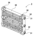
- the power supply device includes a battery laminate 10 in which a plurality of square battery cells 1 are laminated, an intermediate plate 3 in which the battery laminate 10 is laminated in the middle of the stacking direction, and a battery stack.
- a power supply device including a pair of end plates 4 arranged at both ends in the stacking direction of the body 10 and bind bars 2 fixed to both side surfaces of the end plate 4 and the intermediate plate 3, wherein the intermediate plate 3 is provided. It is provided with metal collars 31 provided on both sides of the above, a fixture 14 for connecting the bind bar 2 to the intermediate plate 3 via the metal collar 31, and an insulating plate 15 fixed to the side surface of the intermediate plate 3.
- the intermediate plate 3 is formed of an insulating plastic molded body 30 on both sides or as a whole, and the plastic molded body 30 is provided by integrally molding an annular rib 32 surrounding the periphery of the metal collar 31 on the side surface.
- the insulating plate 15 is fixed to the opening edge of the annular rib 32, the insulating plate 15 closes the opening of the annular rib 32, and the annular rib 32 and the insulating plate 15 insulate the outside of the metal collar 31.
- the fixture 14 penetrates the insulating plate 15 and is connected to the metal collar 31.
- the electric vehicle includes the power supply device 100, a traveling motor 93 to which power is supplied from the power supply device 100, a vehicle body 91 including the power supply device 100 and the motor 93, and a motor 93. It is equipped with wheels 97 that are driven by the vehicle and run the vehicle body 91.
- the power storage device includes the power supply device 100 and a power supply controller 88 that controls charging / discharging to the power supply device 100, and the power supply controller 88 is used to power the battery cell 1 from the outside. It enables charging and controls the battery cell 1 to be charged.
- the metal collar can be effectively insulated with a simple structure and the insulation resistance of the power supply device can be maintained high.
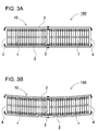
- FIG. 3A is a schematic plan view of the power supply device of FIG. 1
- FIG. 3B is a schematic plan view showing a state in which an external force is applied to the side surface of the power supply device of FIG. 3A.
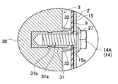
- FIG. 5 is a sectional view taken along line VI-VI of the power supply device shown in FIG.
- FIG. 6 is an enlarged cross-sectional view showing a connected state of the annular rib of the intermediate plate and the insulating plate shown in FIG.
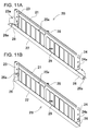
- FIG. 11A is a perspective view showing a state before bending of the protruding piece in the bind bar according to the modified example
- FIG. 11B is a perspective view showing a state in which the protruding piece of FIG. 11A is bent.
- FIG. 15 is an exploded perspective view showing a conventional power supply device.
- 16A is a schematic plan view of a power supply device without an intermediate bracket
- FIG. 16B is a schematic plan view showing a state in which an external force is applied to the side surface of the power supply device of FIG. 16A.
- FIG. 17 is a schematic plan view showing a conventional power supply device.
- the power supply device of the first embodiment of the present invention comprises a battery laminate formed by stacking a plurality of square battery cells, an intermediate plate laminated in the middle of the stacking direction of the battery laminate, and a battery laminate.
- a power supply device including a pair of end plates arranged at both ends in the stacking direction and bind bars fixed to both side surfaces of the end plate and the intermediate plate, and a metal collar provided on both sides of the intermediate plate.
- the intermediate plate is provided with a fixture for connecting the bind bar to the intermediate plate via a metal collar and an insulating plate fixed to the side surface of the intermediate plate, and the intermediate plate is made of an insulating plastic molded body on both sides or the whole.
- the plastic molded body is provided with an annular rib that surrounds the metal collar integrally molded on the side surface, and an insulating plate is fixed to the opening edge of the annular rib, so that the insulating plate is an annular rib.
- An annular rib and an insulating plate insulate the outside of the metal collar by closing the opening of the metal collar, and a fixture penetrates the insulating plate and is connected to the metal collar.
- the above power supply device has a feature that it can effectively insulate the metal collar and increase the insulation resistance of the device while having an extremely simple structure. That is, the above power supply device integrally forms an annular rib that surrounds the metal collar on the plastic molded body of the intermediate plate, and closes the opening edge of the annular rib with an insulating plate to form the annular rib. This is because the insulating plate insulates the outside of the metal collar. In particular, the above power supply device is easy because the plastic molded body forming the intermediate plate and the annular rib are integrally molded without providing a dedicated member for insulating the periphery of the metal collar.
- the annular ribs can be easily and without the addition of special parts, without the need for the process of arranging the annular ribs in the correct position with respect to the metal collar, and even in a harsh usage environment subject to vibration for a long period of time. Is placed at an accurate position around the metal collar without misalignment, and the metal collar is always insulated in an ideal state, and the insulation resistance of the device can be maintained high.
- the annular rib is closed by the insulating plate to insulate the periphery of the metal collar, the creepage distance between the electrode terminal and the bind bar and the metal collar is maintained by both the annular rib and the insulating plate. It also realizes the feature that it can be lengthened to effectively suppress the decrease in insulation resistance due to condensed water.
- the opening edge of the annular rib is brought into close contact with the inner surface of the insulating plate.
- the insulating plate is provided with a fitting groove on the inner surface for fitting the opening edge of the annular rib, and the opening edge of the annular rib is connected to the fitting groove in a fitting structure. doing.
- the metal collar is insert-molded and fixed to the plastic molded body of the intermediate plate.
- the power supply device has a female screw hole in which the fixture is a set screw and the metal collar is for screwing the set screw.
- the entire intermediate plate is made of a plastic molded body.
- the metal collar has through holes, and the fixture passes through the through holes of the metal collar formed on both sides of the intermediate plate and the intermediate plate. It is fixed to the bind bar.
- the power supply device 100 according to the embodiment of the present invention is shown in FIGS. 1 and 2.
- the power supply device 100 shown in these figures shows an example of an in-vehicle power supply device.
- the power supply device 100 is mainly mounted on an electric vehicle such as a hybrid vehicle or an electric vehicle, and is used as a power source for supplying electric power to a traveling motor of the vehicle to drive the vehicle.
- the power supply device of the present invention can be used for electric vehicles other than hybrid vehicles and electric vehicles, and can also be used for applications such as uninterruptible power supplies that require a large output other than electric vehicles.
- the power supply device 100 shown in FIGS. 1 and 2 includes a battery laminate 10 in which a plurality of battery cells 1 are laminated, an intermediate plate 3 formed by laminating in the middle of the battery laminate 10 in the stacking direction, and a battery laminate 10. It includes a pair of end plates 4 arranged at both ends in the stacking direction, and a bind bar 2 fixed to the end plates 4.
- the battery cell 1 has a plate-like outer shape whose outer shape is thinner than the width, and has a rectangular main surface, and a plurality of batteries are laminated. Further, the battery cells 1 are insulated from each other by an insulating member such as a separator 12. Further, an intermediate plate 3 is laminated in the middle of the battery laminate 10.
- the end faces on both sides of the battery laminate 10 are covered with the end plates 4.
- the pair of end plates 4 are fixed to each other by the bind bar 2, and the battery laminate 10 is sandwiched between the end plates 4.
- the outer can of the battery cell 1 has a square shape whose outer shape is thinner than the width.
- the outer can is formed in the shape of a bottomed cylinder with an opening at the top, and the opening is closed with a sealing plate.
- the electrode assembly is housed in the outer can.
- the sealing plate is provided with positive and negative electrode terminals and a gas discharge valve between the electrode terminals.
- the surface of the outer can of the battery cell is covered with an insulating film (not shown) such as a heat-shrinkable tube. Since the surface of the sealing plate is provided with electrode terminals and discharge valves, it is not covered with an insulating film and is exposed.
- the battery cells 1 are electrically connected to each other by a bus bar 13 or the like.
- the bus bar 13 is formed by bending a metal plate.
- An insulating member such as a resin separator 12 is interposed between the adjacent battery cells 1 to insulate between them.
- Battery cells whose surface is coated with an insulating film can also be laminated without a separator.
- the separator 12 is interposed between the main surfaces of the adjacent battery cells 1 facing each other to insulate them.
- the separator 12 is also arranged between the battery cells 1 and the end plate 4 at both ends, and between the battery cell 1 and the intermediate plate 3 in the middle.
- the separator 12 is made of an insulating material in the form of a thin plate or sheet.
- the separator 12 shown in the figure has a plate shape having a size substantially equal to the facing surface of the battery cell 1, and the separator 12 is laminated between the battery cells 1 adjacent to each other to insulate the adjacent battery cells 1 from each other. ing.
- a separator having a shape that forms a flow path of the cooling gas between adjacent battery cells can be used, and the cooling gas can be forcibly blown into the flow path to cool the battery cell.
- the material of the separator 12 is insulating.
- a resin such as plastic
- it can be constructed lightweight and inexpensively.
- it may be a flexible member.
- the separator 12 having no cooling gap can be made of a thin and flexible material such as a sheet. If a separator having an adhesive surface coated on one side as a sheet is used, it can be easily attached to an area requiring insulation such as a main surface or a part of a side surface of the battery cell 1.
- the sheet shape makes it easy to reduce the thickness of the separator, and it is possible to suppress an increase in the thickness and weight of the battery laminate 10.
- End plate 4 A pair of end plates 4 are arranged on both end surfaces of the battery laminate 10 in which the battery cells 1 and the separator 12 are alternately laminated, and the battery laminate 10 is fastened by the pair of end plates 4.
- the end plate 4 is made of a material that exhibits sufficient strength, for example, metal.
- the end plate may be made of resin, or the end plate made of resin may be reinforced with a member made of metal.
- the end plate 4 is composed of one metal plate.
- the bind bars 2 are arranged on both side surfaces of the battery laminate 10 in which the end plates 4 are laminated on both ends, and the ends are fixed to the pair of end plates 4 to form the battery laminate. Conclude 10.
- the bind bar 2 is formed in a plate shape extending in the battery stacking direction of the battery stack 10.
- the bind bar 2 has a flat plate-shaped fastening main surface 25 that covers the side surface of the battery laminate 10, and the first bent piece 21 and the second bent piece as bent pieces whose edges are bent. It has a piece 22, a third bent piece 23, and a fourth bent piece 24.
- the first bent piece 21 is an upper end bent piece in which one of the end edges along the longitudinal direction of the fastening main surface 25, here, the upper end side is bent.
- the second bent piece 22 is a lower end bent piece obtained by bending the other end edge of the fastening main surface 25 along the longitudinal direction, here the lower end side.
- the third bent piece 23 is an end plate fixing piece whose end edge intersecting the longitudinal direction of the fastening main surface 25, in which the front side is partially bent.
- the fourth bent piece 24 is an end plate fixing piece in which the rear side of the edge intersecting the longitudinal direction of the fastening main surface 25 is partially bent.
- a bent metal plate is preferably used.
- the bind bar 2 needs to have sufficient strength so as to hold the battery laminate 10 for a long period of time. Therefore, high-strength steel, general steel, stainless steel, aluminum alloy, magnesium alloy, etc., which are excellent in rigidity and heat conduction, or a combination thereof can be used.
- a metal plate made of Fe-based metal is used.
- the bind bar can have other shapes.
- both ends of the metal plate extended in a strip shape may be bent in a U-shape in a cross-sectional view.
- the position where the bind bar is provided can be the side surface of the battery laminate or the upper and lower surfaces.
- the structure for fixing the bind bar to the end plate is not limited to screwing, and known fixing structures such as rivets, caulking, welding, and adhesion can be appropriately used.
- an opening region 25a may be provided on the fastening main surface 25 of the bind bar 2 so that cooling gas can be blown between the battery cells 1. In the examples of FIGS.
- a plurality of opening regions 25a are provided on the fastening main surface 25 of the bind bar 2 so that the side surface of the battery cell 1 is exposed to the side surface of the battery laminate 10. Further, it is preferable that the bind bar 2 is made of metal in order to prevent the strength of the bind bar 2 from being lowered by providing the opening region 25a.
- the intermediate plate fixing portion 27 for connecting to the intermediate plate 3.
- the battery cell 1 is not located in the portion of the intermediate plate 3, there is no cooling gap for cooling the battery cell 1, and therefore it is not necessary to provide an opening region.
- by not providing the opening region or reducing the area of the opening region in the portion where the strength is required it is possible to avoid the decrease in strength and the decrease in rigidity while ensuring the cooling performance of the battery cell 1.
- the space between the bind bar 2 and the battery laminate 10 is prevented.
- the insulating material 9 is interposed between the metal bind bar 2 and the battery laminate 10.
- the insulating material 9 is made of an insulating member such as a resin sheet or paper.
- the shape of the insulating material 9 is substantially the same as that of the bind bar 2, so that the side surface of the battery laminate 10 does not come into contact with the bind bar 2.
- the opening region 9a is also opened in the insulating material 9 so as not to block the opening region 25a.
- an intermediate plate 3 is interposed in the intermediate portion of the battery laminate 10.
- the battery laminate 10 of FIGS. 1 to 4 is provided with one intermediate plate 3 in the center, it does not necessarily have to be in the center and may be provided between the battery laminates in the stacking direction. That is, the meaning of "intermediate in the stacking direction of the battery laminate” means “between the stacking directions of the battery laminate”.
- the long battery laminate may be provided with a plurality of intermediate plates in the middle.
- the intermediate plate 3 is fixed in the middle of the bind bar 2 in the longitudinal direction. Therefore, the bind bar 2 has an intermediate plate fixing portion 27 for fixing to the intermediate plate 3 in the middle in the longitudinal direction.
- the intermediate plate 3 fixes the metal collar 31 to be fixed to the intermediate plate fixing portion 27.
- the intermediate plate 3 by reinforcing the intermediate portion of the battery laminate 10 with the intermediate plate 3, there is an advantage that the rigidity can be maintained even when the number of stacked battery cells 1 increases.
- a configuration is adopted in which the end plates 904 on both end surfaces are fastened with the bind bar 902.
- 18 thin square battery cells 901 are laminated via a separator 912, end plates 904 are arranged on the end faces of the battery laminate 910, and end plates 904 on both end faces are fastened to each other with bind bars 902. doing.
- the battery cell 901 narrowly held by the bind bar 902 and the battery laminate 910 of the separator 912 are not fixed to the bind bar 902.
- the intermediate plate 3 is provided in the intermediate portion of the bind bar 2, and is further fixed to each of the pair of bind bars 2.
- the pair of bind bars 2 are fixed to each other at the intermediate portion via the intermediate plate 3.
- the effect of suppressing the variation in thickness between the battery cells by the intermediate plate 3 can be obtained. That is, as the number of stacked battery cells is increased, the variation in the thickness of each battery cell 901 is accumulated as shown in FIG. Similarly, since the separator 912 also has a manufacturing tolerance, the thickness variation is accumulated as in the case of the number of battery cells 901.
- the length of the bind bar 902 corresponds to the variation in the thickness of the battery cell 901 and the separator 912 as shown in FIG. If the length is not set, it will be difficult to maintain an appropriate holding state.
- the intermediate plate 3 in the middle as shown in FIG. 4, one surface of the intermediate plate 3 and one end plate 4, and the other surface of the intermediate plate 3 and the other end plate 4 Since the battery laminate 10 can be divided into two parts and sandwiched between the two, the number of layers of the divided battery laminates 10 can be halved, and such a cumulative error can be reduced to reduce the cumulative error in the bind bar 2. It can be easily fastened. In other words, it is possible to suppress variations in the fastening state of the bind bar 2 between the power supply devices, maintain the fastening state of each power supply device constant, and improve reliability.
- the position where the intermediate plate 3 is arranged on the bind bar 2 is preferably approximately the center in the longitudinal direction of the bind bar 2. However, it does not prevent the intermediate plate from being placed and fixed at a position slightly eccentric to either one. In particular, when the number of stacked battery cells is even, it is possible to arrange the intermediate plate in the center, but when the number is odd, it becomes difficult to arrange the intermediate plate in the middle.
- the present invention can also be preferably used in such an embodiment. Further, when a plurality of intermediate plates are provided, it is also preferable to arrange the plurality of intermediate plates at equal intervals in the longitudinal direction of the bind bar 2.
- the intermediate plate 3 is preferably made of insulating plastic.
- the intermediate plate is not entirely made of plastic.
- both side portions and upper and lower portions of the quadrangle, that is, the outer peripheral portion and both sides may be made of plastic and the other parts may be made of metal.
- This intermediate plate can be manufactured by insert molding a metal plate into plastic to insulate the surface with plastic.
- the above intermediate plate 3 can be reliably insulated from the battery cells 1 laminated on both sides.
- Examples of the resin material for forming the intermediate plate include crystalline polymer (LCP), polyphenylene sulfide (PPS), polyethersulfone (PES), polybutylene terephthalate (PBT), polyamideimide (PAI), and polyphthalamide (PPA). , Polyetheretherketone (PEEK), polycarbonate and the like can be used.
- LCP crystalline polymer
- PPS polyphenylene sulfide
- PES polyethersulfone
- PBT polybutylene terephthalate
- PAI polyamideimide
- PPA polyphthalamide
- PEEK Polyetheretherketone
- the intermediate plate 3 has metal collars 31 fixed on both sides to fix the bind bar 2.
- the metal collar 31 is preferably insert-molded and fixed to the intermediate plate 3.
- the metal collar 31 shown in the cross-sectional view of FIG. 6 is provided with a ring-shaped groove 31b on the outer peripheral surface in order to be firmly fixed to the intermediate plate 3.
- a large number of protrusions can be provided on the outer peripheral surface.
- the metal collar 31 which is insert-molded and fixed is firmly fixed to the exact position of the intermediate plate 3. However, the metal collar can be glued or press-fitted to be fixed to the intermediate plate.
- the hybrid structure in which the metal collar 31 is insert-molded and fixed to the plastic intermediate plate 3 is a fixing portion with the bind bar 2 which is required to have strength and durability while making the intermediate plate 3 lightweight and easy to mold. Is made of metal, which makes it possible to increase reliability.
- the intermediate plate 3 described above is made of plastic, and the metal collar 31 is insert-molded and fixed, but the metal collar can also be integrated with the intermediate plate. A part of this intermediate plate is made of metal and has a structure integrated with a metal collar, and the surface of the metal intermediate plate is insulated with plastic or the like.
- This intermediate plate can be realized by a structure in which the portion to be molded integrally with the metal collar is made of die-cast aluminum and the surface is insulated with plastic or the like.
- the metal collar 31 is fixed to the intermediate plate 3 at a plurality of places on both side surfaces, and the bind bar 2 is securely fixed.
- the intermediate plates 3 of FIGS. 5 and 6 have metal collars 31 fixed at three locations, one above the other and one at the center. Although the number of metal collars 31 fixed to the intermediate plate 3 is not specified, the bind bar 2 can be securely fixed by being fixed at the top and bottom and in the middle thereof.
- the metal collar 31 protrudes from the side surface of the intermediate plate 3 and is fixed so that the tip is flat. Further, the metal collar 31 is provided with a female screw hole 31a in the central portion. A set screw 14A penetrating the bind bar 2 is screwed into the female screw hole 31a to connect the bind bar 2 to the intermediate plate 3.
- the metal collar 31 is electrically connected to the ground line via the metal bind bar 2. This is because the bind bar 2 is connected to the base on which the power supply device is installed, or to the chassis in the vehicle.
- the metal collar 31 electrically connected to the ground line is connected to the electrode terminal of the battery cell 1 or the bus bar via condensed water or the like, the insulation resistance is lowered. This is because the conductive dew condensation water electrically connects the metal collar 31 to the ground line.
- the left and right metal collars 31 are provided on both side surfaces of the intermediate plate 3 on the same straight line.
- the metal collar can also be configured to penetrate the intermediate plate, which can improve its strength.
- the intermediate plate 3 Since the power supply device 100 is used in an environment where external conditions such as temperature change, when the air in contact with the surface is cooled and becomes supersaturated, water vapor in the air is liquefied and adheres to the surface as condensed water. To do.
- the intermediate plate 3 is provided with an annular rib 32 that surrounds the metal collar 31 integrally molded on the side surface. Since the intermediate plate 3 described above is entirely made of plastic, the entire intermediate plate 3 is made of a plastic molded body 30. The annular rib 32 is integrally molded with the plastic molded body 30 to be provided.
- the metal collar 31 is arranged inside the annular rib 32, and the periphery of the metal collar 31 is insulated by the annular rib 32.
- the entire intermediate plate 3 is composed of the plastic molded body 30, but the intermediate plate does not necessarily have the entire intermediate plate as a plastic molded body.
- the core material may be a metal plate and the surface may be a plastic molded body. it can.
- This intermediate plate is manufactured in a structure in which a metal plate is insert-molded and embedded in a plastic molded body.
- the intermediate plate 3 having a part of the plastic molded body 30 is composed of at least both side portions of the plastic molded body 30 to form the annular rib 32 as an integral structure. Mold.
- the annular rib 32 is fixed so that the insulating plate 15 is in close contact with the opening edge, and the opening is closed by the insulating plate 15.
- the insulating plate 15 is pressed against the annular rib 32 by the bind bar 2 arranged on the outer surface and is in close contact with the insulating plate 15 without a gap.
- the annular rib 32 of FIG. 7 is gradually sharpened at the tip edge and crushed by the insulating plate 15 to be pressed, so that the annular rib 32 is more reliably adhered without a gap.
- the through hole 15a which is slightly smaller than the outer diameter of the set screw 14A, is widened by the set screw 14A to be inserted and comes into close contact with the surface of the set screw 14A.
- the insulating plate 15 can watertightly seal the opening of the annular rib 32 to insulate the metal collar 31 in an ideal state.
- the through hole 15a can be made larger than the outer diameter of the set screw 14A so that a gap is formed when the set screw 14A is inserted.
- the insulating plate 15 does not hermetically seal the opening of the annular rib 32, but the annular rib 32 and the insulating plate 15 cover the outside of the metal collar 31 to increase the creepage distance and suppress the decrease in insulation resistance. To do.
- a set screw 14A penetrating the intermediate plate fixing portion 27 which is a through hole provided in the bind bar 2 and the through hole 9b provided in the insulating material 9 is inserted through the through hole 15a and the metal collar 31 is inserted.
- the opening edge of the annular rib 32 is pressed into close contact with the opening of the annular rib 32 to close the opening.
- the insulating plate 15 can be mass-produced at low cost while having the optimum material and shape. Further, by using the insulating plate as a separate member, it is possible to simplify the handling and improve the manufacturing efficiency.
- the insulating plate may have an integral structure with the insulating material.
- the insulating plate is integrally manufactured as a part of an insulating material manufactured in the form of a plate or a sheet. This insulating plate is also arranged in a fixed position with respect to the side surface of the intermediate plate in a state where the insulating material is connected to the fixed position of the bind bar to close the opening of the annular rib. Further, the insulating plate can be fixed to the inner surface of the insulating material as a plurality of plate materials facing each annular rib.
- the bind bar 2 is provided with an intermediate plate fixing portion 27 for fixing to the metal collar 31 of the intermediate plate 3 in the middle in the longitudinal direction.
- the direction of the fixture 14 for fixing the intermediate plate 3 and the bind bar 2 is set to be substantially perpendicular to the main surface of the bind bar 2.
- the metal collar 31 is a metal cylinder provided with a through hole 31c, and the metal collar 31 is insert-molded into a plastic molded body 30 so as to penetrate the intermediate plate 3 in the width direction. And manufacture.
- the fixture 14 shown in FIG. 8 is composed of a bolt 14B having a threaded portion longer than the width of the intermediate plate and a nut member 14C screwed into the bolt 14B.
- the nut member 14C is attached to the tip of the intermediate plate 3 in a state where the front end of the screw portion of the bolt penetrating the metal collar 31 is projected from the opposite side surface and is penetrated through the insulating plate 15 and the bind bar 2.
- the structure is such that the bind bar 2 is fixed to both side surfaces of the intermediate plate 3 by screwing.
- the fixture penetrating the intermediate plate may be composed of a screw rod longer than the width of the intermediate plate 3 and nut members connected to both ends of the screw rod.
- a plurality of fixing structures for fixing the bind bar 2 to the intermediate plate 3 may be provided.
- a second fixing portion 28 on the fastening member side may be provided in the middle of the first bent piece 21.
- the bind bar 2 shown in FIGS. 1, 2 and 6 forms a first bent piece screw hole protruding from the center of the first bent piece 21 as the second fixing portion 28 on the fastening member side. ..
- the second fixing portion 28 on the fastening member side at the portion intersecting the intermediate plate fixing portion 27, the bind bar 2 and the intermediate plate 3 can be fixed at positions intersecting each other, which are different. A stronger fixing structure from the direction is realized.
- a second screw hole on the bracket side is opened as a second fixing portion 38 on the bracket side at a portion facing the first bent single screw hole.
- the intermediate plate 3 is also provided with a bracket-side third screw hole as a bracket-side third fixing portion 39 at a position corresponding to the fastening member-side third fixing portion 29.
- the intermediate portion is opened to reduce the amount of resin used.
- the separator having a ventilation gap is arranged on both sides of the intermediate plate, the separator is formed in a shape that matches the shape of the separator, for example, the unevenness of the cooling gap.
- the side surface of the battery cell 1 is coated with the separator 12 and joined to the intermediate plate 3.
- a separator 12 is interposed between the battery cell 1 and the intermediate plate 3.
- the separator may be omitted for the battery cell in contact with the intermediate plate.
- the above-mentioned cooling gap or the like may be formed on the surface of the intermediate plate so that the surface of the battery cell can be covered with the side surface of the intermediate plate.
- the bind bar 2 has a structure in which the end edges of the fastening main surface 25 are bent, respectively, and further bent to fix the bent pieces to each other to increase the strength. It can also be improved.
- Such an example is shown in the perspective views of FIGS. 11A and 11B as the bind bar 2B according to the modified example.
- the bind bar 2B shown in these figures has a protruding piece 26 in which the second bent piece 22 has its longitudinal end protruding from the edge of the fastening main surface 25.
- the protruding piece 26 has a protruding piece side screw hole 26a for screwing with the end plate 4.
- the third bent piece 23 and the fourth bent piece 24 have a third screw hole 23a and a fourth screw hole 24a, respectively.
- the projecting piece 26 is bent from the state of FIG. 11A so as to overlap the second bent piece 22 as shown in FIG. 11B. In this state, the protruding one-side screw hole 26a, the third screw hole 23a, and the fourth screw hole 24a are aligned, screwed into a common screw, and fixed to the end plate 4.
- the surfaces where the bind bar 2B is screwed with the end plate 4 are three-dimensionally configured by the intersecting surfaces, and a stronger fixing structure is realized.
- the above power supply device can be used as a power source for a vehicle that supplies electric power to a motor that runs an electric vehicle.
- an electric vehicle equipped with a power supply device an electric vehicle such as a hybrid vehicle or a plug-in hybrid vehicle that runs on both an engine and a motor, or an electric vehicle that runs only on a motor can be used, and is used as a power source for these vehicles.
- an electric vehicle such as a hybrid vehicle or a plug-in hybrid vehicle that runs on both an engine and a motor, or an electric vehicle that runs only on a motor can be used, and is used as a power source for these vehicles.
- FIG. 12 shows an example in which a power supply device is mounted on a hybrid vehicle that runs on both an engine and a motor.
- the vehicle HV equipped with the power supply device shown in this figure includes a vehicle body 91, an engine 96 for traveling the vehicle body 91, a motor 93 for traveling, and wheels driven by these engines 96 and a motor 93 for traveling. 97, a power supply device 100 for supplying electric power to the motor 93, and a generator 94 for charging the battery of the power supply device 100 are provided.
- the power supply device 100 is connected to the motor 93 and the generator 94 via the DC / AC inverter 95.
- the vehicle HV runs on both the motor 93 and the engine 96 while charging and discharging the battery of the power supply device 100.
- the motor 93 is driven to drive the vehicle in a region where the engine efficiency is low, for example, when accelerating or traveling at a low speed.
- the motor 93 is driven by being supplied with electric power from the power supply device 100.
- the generator 94 is driven by the engine 96 or by regenerative braking when braking the vehicle to charge the battery of the power supply device 100.
- the vehicle HV may be provided with a charging plug 98 for charging the power supply device 100. By connecting the charging plug 98 to an external power source, the power supply device 100 can be charged.
- FIG. 13 shows an example in which a power supply device is mounted on an electric vehicle traveling only by a motor.
- the vehicle EV equipped with the power supply device shown in this figure supplies electric power to the vehicle body 91, the motor 93 for traveling the vehicle body 91, the wheels 97 driven by the motor 93, and the motor 93.
- the power supply device 100 and the generator 94 for charging the battery of the power supply device 100 are provided.
- the power supply device 100 is connected to the motor 93 and the generator 94 via the DC / AC inverter 95.
- the motor 93 is driven by being supplied with electric power from the power supply device 100.
- the generator 94 is driven by the energy used for regenerative braking of the vehicle EV to charge the battery of the power supply device 100.
- the vehicle EV is provided with a charging plug 98, and the charging plug 98 can be connected to an external power source to charge the power supply device 100.
- the power supply device for power storage device
- the present invention does not specify the use of the power supply device as the power source of the motor for traveling the vehicle.
- the power supply device according to the embodiment can also be used as a power source for a power storage device that charges and stores a battery with electric power generated by solar power generation, wind power generation, or the like.
- FIG. 14 shows a power storage device in which the battery of the power supply device 100 is charged by the solar cell 82 to store electricity.
- the power storage device shown in FIG. 14 charges the battery of the power supply device 100 with the electric power generated by the solar cells 82 arranged on the roof or roof of a building 81 such as a house or factory.
- This power storage device uses the solar cell 82 as a power source for charging, charges the battery of the power supply device 100 with the charging circuit 83, and then supplies power to the load 86 via the DC / AC inverter 85. Therefore, this power storage device has a charge mode and a discharge mode.
- the DC / AC inverter 85 and the charging circuit 83 are connected to the power supply device 100 via the discharge switch 87 and the charging switch 84, respectively.
- the ON / OFF of the discharge switch 87 and the charge switch 84 is switched by the power controller 88 of the power storage device.
- the power controller 88 switches the charging switch 84 to ON and the discharge switch 87 to OFF to allow the charging circuit 83 to charge the power supply device 100.
- the power controller 88 turns off the charging switch 84 and turns on the discharge switch 87 to switch to the discharge mode, and the power supply device 100 Allows discharge from to load 86.
- the charge switch 84 can be turned on and the discharge switch 87 can be turned on to supply power to the load 86 and charge the power supply device 100 at the same time.
- the power supply device can also be used as a power source for a power storage device that charges and stores batteries by using midnight power at night.
- a power supply device charged with midnight power can be charged with midnight power, which is surplus power of a power plant, and output power in the daytime when the power load is large, so that the peak power in the daytime can be limited to a small value.
- the power supply can also be used as a power source for charging with both solar cell output and midnight power. This power supply device can effectively utilize both the power generated by the solar cell and the midnight power, and can efficiently store electricity while considering the weather and power consumption.
- the above-mentioned power storage devices include backup power supply devices that can be mounted in computer server racks, backup power supply devices for wireless base stations such as mobile phones, power storage power supplies for homes or factories, power supplies for street lights, etc. It can be suitably used for power storage devices combined with solar cells, backup power sources for traffic lights and traffic indicators for roads, and the like.
- the power supply device according to the present invention and the electric vehicle and power storage device provided with this power supply device are for large currents used for power supply of motors for driving electric vehicles such as hybrid vehicles, fuel cell vehicles, electric vehicles, and electric motorcycles.
- a power supply device for a plug-in type hybrid electric vehicle, a hybrid electric vehicle, an electric vehicle, or the like that can switch between an EV driving mode and a HEV driving mode can be mentioned.
- a backup power supply device that can be mounted in a computer server rack, a backup power supply device for wireless base stations such as mobile phones, a power storage device for home use and factories, a power storage device for street lights, etc. , Can also be used as appropriate for backup power supplies such as traffic lights.
Abstract
In order to effectively insulate a metal collar with a simple structure and maintain a high insulation resistance of the device, in this power supply device, an intermediate plate (3) is laminated in the middle of a battery laminate of multiple square battery cells, a pair of end plates are arranged on both ends thereof, and binder bars (2) are fixed on the end plates and the intermediate plate (3); the power supply device is provided with metal collars (31) which are provided on both sides of the intermediate plate (3), fixing jigs (14) which link the binder bar (2) to the intermediate plate (3), and an insulation plate (15) which is fixed to the side surface of the intermediate plate (3). The intermediate plate (3) is configured from an insulating molded plastic body (30), and annular ribs (32) surrounding the metal collars (31) are integrally formed on the side surface thereof. The insulation plate (15) is fixed to the open edge of the annular ribs (32), closing the opening in the annular ribs (32); the outside of the metal collars (31) are insulated by the annular ribs (32) and the insulation plate (15); and fixing jigs (14) pass through the insulation plate (15) and are connected to the metal collars (31).
Description
本発明は、複数の角形電池セルを積層している電源装置とこの電源装置を備える電動車両及び蓄電装置に関する。
The present invention relates to a power supply device in which a plurality of square battery cells are stacked, an electric vehicle equipped with this power supply device, and a power storage device.
二次電池を用いた電源装置が車両の駆動用電源等の用途で利用されている。このような電源装置は、図15の分解斜視図に示すように、複数枚の電池セル901を積層している電池積層体910の端面にエンドプレート904を配置し、エンドプレート904を左右一対のバインドバー902で締結する構成が一般に採用されている。このような電源装置900において、出力を向上させるためには、電池セル901の数を増やすことが挙げられる。
A power supply device using a secondary battery is used as a power source for driving a vehicle. In such a power supply device, as shown in the exploded perspective view of FIG. 15, the end plates 904 are arranged on the end faces of the battery laminate 910 in which a plurality of battery cells 901 are laminated, and the end plates 904 are paired on the left and right. A configuration in which the binding bar 902 is fastened is generally adopted. In such a power supply device 900, in order to improve the output, it is possible to increase the number of battery cells 901.
しかしながら、上記のようなエンドプレート904とバインドバー902を用いた構成においては、電池セル901の数が増加すると、電池積層体910が長くなり、これに応じて相応の剛性アップが要求される。例えば、図16A、図16Bに示すように、電池積層体910の側面に外力が加えられると、一方のバインドバー902に負荷が掛かる。よって、これに対応するためにはバインドバー902の剛性を上げる必要が生じ、このためバインドバー902を構成する金属板を厚くしたり、より強固な材質を使用する等の対策が必要となり、重量が重くなったりコストが高くなるという問題が生じる。また、電池セル数が増すにつれて、中央に位置する電池セル901の位置ずれがより大きくなるという懸念も生じる。以上の弊害を防止するために、電池積層体の中間に中間プレートを配置して、中間プレートをバインドバーに固定する電源装置が開発されている。(特許文献1参照)
However, in the configuration using the end plate 904 and the bind bar 902 as described above, as the number of battery cells 901 increases, the battery laminate 910 becomes longer, and a corresponding increase in rigidity is required accordingly. For example, as shown in FIGS. 16A and 16B, when an external force is applied to the side surface of the battery laminate 910, a load is applied to one of the bind bars 902. Therefore, in order to cope with this, it is necessary to increase the rigidity of the bind bar 902, and for this reason, it is necessary to take measures such as thickening the metal plate constituting the bind bar 902 or using a stronger material, and the weight. There is a problem that it becomes heavy and the cost becomes high. Further, as the number of battery cells increases, there is a concern that the misalignment of the battery cell 901 located at the center becomes larger. In order to prevent the above adverse effects, a power supply device has been developed in which an intermediate plate is arranged in the middle of the battery laminate and the intermediate plate is fixed to the bind bar. (See Patent Document 1)
特許文献1の電源装置は、中間プレートをバインドバーに固定して電池セルを定位置に配置できるが、バインドバーを固定するために中間プレートの両側に設けている金属カラーの表面に付着する結露水が、装置の絶縁抵抗を低下させる原因となる。電源装置は、電位のある電極端子やこれに接続しているバスバーとグランドラインとの間の絶縁抵抗を高く、例えば数十MΩ以上に維持することが要求される。金属カラーは、金属製のバインドバーやエンドプレートを介してグランドラインに接続されるので、グランドラインに接続される金属カラーと電位のある電極端子やバスバーとの間の絶縁抵抗は高く維持することが要求される。金属カラーを両側面に固定している中間プレートは、両面に電池セルを積層して、この電池セルには電極端子にバスバーが接続されて、電極端子やバスバーが金属カラーの近傍に配置されるので、金属カラー近傍に付着する結露水は、金属カラーを電極端子やバスバーに導通して、絶縁抵抗を低下させる原因となる。
In the power supply device of Patent Document 1, the intermediate plate can be fixed to the bind bar and the battery cell can be arranged in a fixed position, but dew condensation adhering to the surface of the metal collar provided on both sides of the intermediate plate to fix the bind bar. Water causes the insulation resistance of the device to decrease. The power supply device is required to maintain a high insulation resistance between the electrode terminal having a potential and the bus bar connected to the electrode terminal and the ground line, for example, several tens of MΩ or more. Since the metal collar is connected to the ground line via a metal bind bar or end plate, the insulation resistance between the metal collar connected to the ground line and the potential electrode terminal or bus bar should be maintained high. Is required. The intermediate plate that fixes the metal collar on both sides has battery cells stacked on both sides, and a bus bar is connected to the electrode terminal of this battery cell, and the electrode terminal and bus bar are arranged near the metal collar. Therefore, the dew condensation water adhering to the vicinity of the metal collar causes the metal collar to conduct to the electrode terminals and the bus bar, thereby lowering the insulation resistance.
本発明は、さらに以上の欠点を解決することを目的に開発されたもので、本発明の目的の一は、極めて簡単な構造で金属カラーを効果的に絶縁し、装置の絶縁抵抗を高く維持できる技術を提供することにある。
The present invention has been developed for the purpose of solving the above-mentioned drawbacks, and one of the purposes of the present invention is to effectively insulate a metal collar with an extremely simple structure and maintain a high insulation resistance of the apparatus. It is to provide the technology that can be done.
本発明のある態様に係る電源装置は、複数の角形の電池セル1を積層してなる電池積層体10と、電池積層体10の積層方向の中間に積層してなる中間プレート3と、電池積層体10の積層方向の両端部に配置してなる一対のエンドプレート4と、エンドプレート4及び中間プレート3の両側面に固定してなるバインドバー2とを備える電源装置であって、中間プレート3の両側に設けてなる金属カラー31と、バインドバー2を金属カラー31を介して中間プレート3と連結する固定具14と、中間プレート3の側面に固定してなる絶縁プレート15とを備えており、中間プレート3は、両側部又は全体を絶縁性のプラスチック成形体30で構成してなり、プラスチック成形体30は、金属カラー31の周囲を囲む環状リブ32を側面に一体的に成形して設けており、環状リブ32の開口縁に絶縁プレート15が固定されて、絶縁プレート15が、環状リブ32の開口部を閉塞して、環状リブ32と絶縁プレート15が、金属カラー31の外側を絶縁しており、固定具14が絶縁プレート15を貫通して金属カラー31に連結されている。
The power supply device according to an aspect of the present invention includes a battery laminate 10 in which a plurality of square battery cells 1 are laminated, an intermediate plate 3 in which the battery laminate 10 is laminated in the middle of the stacking direction, and a battery stack. A power supply device including a pair of end plates 4 arranged at both ends in the stacking direction of the body 10 and bind bars 2 fixed to both side surfaces of the end plate 4 and the intermediate plate 3, wherein the intermediate plate 3 is provided. It is provided with metal collars 31 provided on both sides of the above, a fixture 14 for connecting the bind bar 2 to the intermediate plate 3 via the metal collar 31, and an insulating plate 15 fixed to the side surface of the intermediate plate 3. The intermediate plate 3 is formed of an insulating plastic molded body 30 on both sides or as a whole, and the plastic molded body 30 is provided by integrally molding an annular rib 32 surrounding the periphery of the metal collar 31 on the side surface. The insulating plate 15 is fixed to the opening edge of the annular rib 32, the insulating plate 15 closes the opening of the annular rib 32, and the annular rib 32 and the insulating plate 15 insulate the outside of the metal collar 31. The fixture 14 penetrates the insulating plate 15 and is connected to the metal collar 31.
本発明のある態様に係る電動車両は、上記電源装置100と、電源装置100から電力供給される走行用のモータ93と、電源装置100及びモータ93を搭載してなる車両本体91と、モータ93で駆動されて車両本体91を走行させる車輪97とを備えている。
The electric vehicle according to an aspect of the present invention includes the power supply device 100, a traveling motor 93 to which power is supplied from the power supply device 100, a vehicle body 91 including the power supply device 100 and the motor 93, and a motor 93. It is equipped with wheels 97 that are driven by the vehicle and run the vehicle body 91.
本発明のある態様に係る蓄電装置は、上記電源装置100と、電源装置100への充放電を制御する電源コントローラ88と備えて、電源コントローラ88でもって、外部からの電力により電池セル1への充電を可能とすると共に、電池セル1に対し充電を行うよう制御している。
The power storage device according to an aspect of the present invention includes the power supply device 100 and a power supply controller 88 that controls charging / discharging to the power supply device 100, and the power supply controller 88 is used to power the battery cell 1 from the outside. It enables charging and controls the battery cell 1 to be charged.
以上の電源装置は、電池積層体に中間プレートを積層してバインドバーに連結しながら、中間プレートを設けることによる絶縁抵抗の低下を抑制することができる。とくに、簡単な構造で金属カラーを効果的に絶縁して、電源装置の絶縁抵抗を高く維持できる特長が実現できる。
In the above power supply device, it is possible to suppress a decrease in insulation resistance due to the provision of the intermediate plate while laminating the intermediate plate on the battery laminate and connecting the intermediate plate to the bind bar. In particular, it is possible to realize the feature that the metal collar can be effectively insulated with a simple structure and the insulation resistance of the power supply device can be maintained high.
以下、図面に基づいて本発明を詳細に説明する。なお、以下の説明では、必要に応じて特定の方向や位置を示す用語(例えば、「上」、「下」、及びそれらの用語を含む別の用語)を用いるが、それらの用語の使用は図面を参照した発明の理解を容易にするためであって、それらの用語の意味によって本発明の技術的範囲が制限されるものではない。また、複数の図面に表れる同一符号の部分は同一もしくは同等の部分又は部材を示す。
さらに以下に示す実施形態は、本発明の技術思想の具体例を示すものであって、本発明を以下に限定するものではない。また、以下に記載されている構成部品の寸法、材質、形状、その相対的配置等は、特定的な記載がない限り、本発明の範囲をそれのみに限定する趣旨ではなく、例示することを意図したものである。また、一の実施の形態、実施例において説明する内容は、他の実施の形態、実施例にも適用可能である。また、図面が示す部材の大きさや位置関係等は、説明を明確にするため、誇張していることがある。 Hereinafter, the present invention will be described in detail with reference to the drawings. In the following description, terms indicating a specific direction or position (for example, "upper", "lower", and other terms including those terms) are used as necessary, but the use of these terms is used. This is for facilitating the understanding of the invention with reference to the drawings, and the meaning of these terms does not limit the technical scope of the present invention. Further, the parts having the same reference numerals appearing in a plurality of drawings indicate the same or equivalent parts or members.
Further, the embodiments shown below show specific examples of the technical idea of the present invention, and do not limit the present invention to the following. In addition, the dimensions, materials, shapes, relative arrangements, etc. of the components described below are not intended to limit the scope of the present invention to the specific description, but are exemplified. It was intended. Further, the contents described in one embodiment and the embodiment can be applied to other embodiments and the embodiments. In addition, the size and positional relationship of the members shown in the drawings may be exaggerated in order to clarify the explanation.
本発明の第1の実施態様の電源装置は、複数の角形の電池セルを積層してなる電池積層体と、電池積層体の積層方向の中間に積層してなる中間プレートと、電池積層体の積層方向の両端部に配置してなる一対のエンドプレートと、エンドプレート及び中間プレートの両側面に固定してなるバインドバーとを備える電源装置であって、中間プレートの両側に設けてなる金属カラーと、バインドバーを金属カラーを介して中間プレートと連結する固定具と、中間プレートの側面に固定してなる絶縁プレートとを備え、中間プレートは、両側部又は全体を絶縁性のプラスチック成形体で構成してなり、プラスチック成形体は、金属カラーの周囲を囲む環状リブを側面に一体的に成形して設けており、環状リブの開口縁に絶縁プレートが固定されて、絶縁プレートが、環状リブの開口部を閉塞して、環状リブと絶縁プレートが、金属カラーの外側を絶縁しており、固定具が絶縁プレートを貫通して金属カラーに連結されている。
The power supply device of the first embodiment of the present invention comprises a battery laminate formed by stacking a plurality of square battery cells, an intermediate plate laminated in the middle of the stacking direction of the battery laminate, and a battery laminate. A power supply device including a pair of end plates arranged at both ends in the stacking direction and bind bars fixed to both side surfaces of the end plate and the intermediate plate, and a metal collar provided on both sides of the intermediate plate. The intermediate plate is provided with a fixture for connecting the bind bar to the intermediate plate via a metal collar and an insulating plate fixed to the side surface of the intermediate plate, and the intermediate plate is made of an insulating plastic molded body on both sides or the whole. The plastic molded body is provided with an annular rib that surrounds the metal collar integrally molded on the side surface, and an insulating plate is fixed to the opening edge of the annular rib, so that the insulating plate is an annular rib. An annular rib and an insulating plate insulate the outside of the metal collar by closing the opening of the metal collar, and a fixture penetrates the insulating plate and is connected to the metal collar.
以上の電源装置は、極めて簡単な構造としながら、金属カラーを効果的に絶縁して、装置の絶縁抵抗を高くできる特徴がある。それは、以上の電源装置が、中間プレートのプラスチック成形体に、金属カラーの周囲を囲む環状リブを一体的に成形して設けて、環状リブの開口縁を絶縁プレートで閉塞して、環状リブと絶縁プレートで金属カラーの外側を絶縁しているからである。とくに、以上の電源装置は、金属カラーの周囲を絶縁するために専用の部材を設けることなく、中間プレートを成形しているプラスチック成形体と環状リブを一体成形して設けているので、簡単かつ容易に、しかも専用部品を追加することなく、さらに環状リブを金属カラーに対して正確な位置に配置する工程も必要なく、さらにまた、長期間にわたって振動などを受ける厳しい使用環境においても、環状リブを位置ずれすることなく金属カラー周囲の正確な位置に配置して、常に金属カラーを理想的な状態で絶縁して、装置の絶縁抵抗を高く維持できる特長がある。
The above power supply device has a feature that it can effectively insulate the metal collar and increase the insulation resistance of the device while having an extremely simple structure. That is, the above power supply device integrally forms an annular rib that surrounds the metal collar on the plastic molded body of the intermediate plate, and closes the opening edge of the annular rib with an insulating plate to form the annular rib. This is because the insulating plate insulates the outside of the metal collar. In particular, the above power supply device is easy because the plastic molded body forming the intermediate plate and the annular rib are integrally molded without providing a dedicated member for insulating the periphery of the metal collar. The annular ribs can be easily and without the addition of special parts, without the need for the process of arranging the annular ribs in the correct position with respect to the metal collar, and even in a harsh usage environment subject to vibration for a long period of time. Is placed at an accurate position around the metal collar without misalignment, and the metal collar is always insulated in an ideal state, and the insulation resistance of the device can be maintained high.
さらに、以上の電源装置は、環状リブを絶縁プレートで閉塞して金属カラーの周囲を絶縁するので、環状リブと絶縁プレートの両方で、電極端子及びバインドバーと金属カラーとの間の沿面距離を長くして、結露水による絶縁抵抗の低下を効果的に抑制できる特長も実現する。
Further, in the above power supply device, since the annular rib is closed by the insulating plate to insulate the periphery of the metal collar, the creepage distance between the electrode terminal and the bind bar and the metal collar is maintained by both the annular rib and the insulating plate. It also realizes the feature that it can be lengthened to effectively suppress the decrease in insulation resistance due to condensed water.
本発明の第2の実施態様の電源装置は、環状リブの開口縁を絶縁プレートの内面に密着させている。
In the power supply device according to the second embodiment of the present invention, the opening edge of the annular rib is brought into close contact with the inner surface of the insulating plate.
本発明の第3の実施態様の電源装置は、絶縁プレートが、環状リブの開口縁を嵌入する嵌合溝を内面に備えており、環状リブの開口縁を嵌合溝に嵌合構造で連結している。
In the power supply device according to the third embodiment of the present invention, the insulating plate is provided with a fitting groove on the inner surface for fitting the opening edge of the annular rib, and the opening edge of the annular rib is connected to the fitting groove in a fitting structure. doing.
本発明の第4の実施態様の電源装置は、金属カラーを中間プレートのプラスチック成形体にインサート成形して固定している。
In the power supply device according to the fourth embodiment of the present invention, the metal collar is insert-molded and fixed to the plastic molded body of the intermediate plate.
本発明の第5の実施態様の電源装置は、固定具が止ネジで、金属カラーが止ネジをねじ込む雌ネジ孔を備えている。
The power supply device according to the fifth embodiment of the present invention has a female screw hole in which the fixture is a set screw and the metal collar is for screwing the set screw.
本発明の第6の実施態様の電源装置は、中間プレート全体をプラスチック成形体としている。
In the power supply device according to the sixth embodiment of the present invention, the entire intermediate plate is made of a plastic molded body.
本発明の第7の実施態様の電源装置は、金属カラーが貫通穴を有し、固定具が、中間プレートの両側に固定してなる金属カラーの貫通穴と、中間プレートとを通過して、バインドバーに固定されている。
In the power supply device according to the seventh embodiment of the present invention, the metal collar has through holes, and the fixture passes through the through holes of the metal collar formed on both sides of the intermediate plate and the intermediate plate. It is fixed to the bind bar.
(実施の形態1)
本発明の一実施形態に係る電源装置100を、図1と図2に示す。これらの図に示す電源装置100は、車載用の電源装置の例を示している。具体的には、この電源装置100は、主としてハイブリッド車や電気自動車等の電動車両に搭載されて、車両の走行モータに電力を供給して、車両を走行させる電源に使用される。ただ、本発明の電源装置は、ハイブリッド車や電気自動車以外の電動車両に使用でき、また電動車両以外の大出力が要求される無停電電源などの用途にも使用できる。 (Embodiment 1)
Thepower supply device 100 according to the embodiment of the present invention is shown in FIGS. 1 and 2. The power supply device 100 shown in these figures shows an example of an in-vehicle power supply device. Specifically, the power supply device 100 is mainly mounted on an electric vehicle such as a hybrid vehicle or an electric vehicle, and is used as a power source for supplying electric power to a traveling motor of the vehicle to drive the vehicle. However, the power supply device of the present invention can be used for electric vehicles other than hybrid vehicles and electric vehicles, and can also be used for applications such as uninterruptible power supplies that require a large output other than electric vehicles.
本発明の一実施形態に係る電源装置100を、図1と図2に示す。これらの図に示す電源装置100は、車載用の電源装置の例を示している。具体的には、この電源装置100は、主としてハイブリッド車や電気自動車等の電動車両に搭載されて、車両の走行モータに電力を供給して、車両を走行させる電源に使用される。ただ、本発明の電源装置は、ハイブリッド車や電気自動車以外の電動車両に使用でき、また電動車両以外の大出力が要求される無停電電源などの用途にも使用できる。 (Embodiment 1)
The
(電源装置100)
図1と図2に示す電源装置100は、電池セル1を複数枚積層した電池積層体10と、電池積層体10の積層方向の中間に積層してなる中間プレート3と、電池積層体10の積層方向の両端部に配置してなる一対のエンドプレート4と、エンドプレート4に固定してなるバインドバー2とを備える。電池セル1は、外形を幅よりも厚さを薄くした板状としており、主面を矩形状として、複数枚を積層している。また、電池セル1同士の間をセパレータ12などの絶縁部材で絶縁している。さらに電池積層体10の中間には、中間プレート3を積層している。さらにまた、電池セル1をセパレータ12を介して交互に積層した状態で、電池積層体10の両側の端面をエンドプレート4で覆っている。この一対のエンドプレート4同士を、バインドバー2で固定して、エンドプレート4同士の間で電池積層体10を狭持する。 (Power supply device 100)
Thepower supply device 100 shown in FIGS. 1 and 2 includes a battery laminate 10 in which a plurality of battery cells 1 are laminated, an intermediate plate 3 formed by laminating in the middle of the battery laminate 10 in the stacking direction, and a battery laminate 10. It includes a pair of end plates 4 arranged at both ends in the stacking direction, and a bind bar 2 fixed to the end plates 4. The battery cell 1 has a plate-like outer shape whose outer shape is thinner than the width, and has a rectangular main surface, and a plurality of batteries are laminated. Further, the battery cells 1 are insulated from each other by an insulating member such as a separator 12. Further, an intermediate plate 3 is laminated in the middle of the battery laminate 10. Furthermore, in a state where the battery cells 1 are alternately laminated via the separator 12, the end faces on both sides of the battery laminate 10 are covered with the end plates 4. The pair of end plates 4 are fixed to each other by the bind bar 2, and the battery laminate 10 is sandwiched between the end plates 4.
図1と図2に示す電源装置100は、電池セル1を複数枚積層した電池積層体10と、電池積層体10の積層方向の中間に積層してなる中間プレート3と、電池積層体10の積層方向の両端部に配置してなる一対のエンドプレート4と、エンドプレート4に固定してなるバインドバー2とを備える。電池セル1は、外形を幅よりも厚さを薄くした板状としており、主面を矩形状として、複数枚を積層している。また、電池セル1同士の間をセパレータ12などの絶縁部材で絶縁している。さらに電池積層体10の中間には、中間プレート3を積層している。さらにまた、電池セル1をセパレータ12を介して交互に積層した状態で、電池積層体10の両側の端面をエンドプレート4で覆っている。この一対のエンドプレート4同士を、バインドバー2で固定して、エンドプレート4同士の間で電池積層体10を狭持する。 (Power supply device 100)
The
(電池セル1)
電池セル1は、その外形を構成する外装缶を、幅よりも厚さを薄くした角形としている。外装缶は上方を開口した有底筒状に形成され、開口部分を封口板で閉塞している。外装缶には、電極組立体が収納される。封口板には正負の電極端子と、この電極端子の間にガス排出弁を設けている。電池セルは、外装缶の表面を熱収縮チューブなどの絶縁膜(図示せず)で被覆している。封口板の表面は、電極端子や排出弁を設けているので、絶縁膜では被覆されず露出している。電池セル1同士は、バスバー13等で電気的に接続される。バスバー13は、金属板を折曲して形成される。 (Battery cell 1)
The outer can of thebattery cell 1 has a square shape whose outer shape is thinner than the width. The outer can is formed in the shape of a bottomed cylinder with an opening at the top, and the opening is closed with a sealing plate. The electrode assembly is housed in the outer can. The sealing plate is provided with positive and negative electrode terminals and a gas discharge valve between the electrode terminals. The surface of the outer can of the battery cell is covered with an insulating film (not shown) such as a heat-shrinkable tube. Since the surface of the sealing plate is provided with electrode terminals and discharge valves, it is not covered with an insulating film and is exposed. The battery cells 1 are electrically connected to each other by a bus bar 13 or the like. The bus bar 13 is formed by bending a metal plate.
電池セル1は、その外形を構成する外装缶を、幅よりも厚さを薄くした角形としている。外装缶は上方を開口した有底筒状に形成され、開口部分を封口板で閉塞している。外装缶には、電極組立体が収納される。封口板には正負の電極端子と、この電極端子の間にガス排出弁を設けている。電池セルは、外装缶の表面を熱収縮チューブなどの絶縁膜(図示せず)で被覆している。封口板の表面は、電極端子や排出弁を設けているので、絶縁膜では被覆されず露出している。電池セル1同士は、バスバー13等で電気的に接続される。バスバー13は、金属板を折曲して形成される。 (Battery cell 1)
The outer can of the
隣接する電池セル1同士の間には、樹脂製のセパレータ12等の絶縁部材が介在されて、これらの間を絶縁する。表面を絶縁膜で被覆している電池セルは、セパレータを介することなく積層することもできる。
An insulating member such as a resin separator 12 is interposed between the adjacent battery cells 1 to insulate between them. Battery cells whose surface is coated with an insulating film can also be laminated without a separator.
(セパレータ12)
セパレータ12は、図2の分解斜視図に示すように、隣接する電池セル1の、対向する主面同士の間に介在されてこれらを絶縁する。また、セパレータ12は、両端の電池セル1とエンドプレート4との間、及び、中間の電池セル1と中間プレート3との間にも配置される。このセパレータ12は、絶縁材で薄いプレート状またはシート状に製作される。図に示すセパレータ12は、電池セル1の対向面とほぼ等しい大きさのプレート状としており、このセパレータ12を互いに隣接する電池セル1の間に積層して、隣接する電池セル1同士を絶縁している。なお、セパレータとして、隣接する電池セルの間に冷却気体の流路を形成する形状のセパレータを使用し、この流路に冷却気体を強制送風して電池セルを冷却することもできる。 (Separator 12)
As shown in the exploded perspective view of FIG. 2, theseparator 12 is interposed between the main surfaces of the adjacent battery cells 1 facing each other to insulate them. The separator 12 is also arranged between the battery cells 1 and the end plate 4 at both ends, and between the battery cell 1 and the intermediate plate 3 in the middle. The separator 12 is made of an insulating material in the form of a thin plate or sheet. The separator 12 shown in the figure has a plate shape having a size substantially equal to the facing surface of the battery cell 1, and the separator 12 is laminated between the battery cells 1 adjacent to each other to insulate the adjacent battery cells 1 from each other. ing. As the separator, a separator having a shape that forms a flow path of the cooling gas between adjacent battery cells can be used, and the cooling gas can be forcibly blown into the flow path to cool the battery cell.
セパレータ12は、図2の分解斜視図に示すように、隣接する電池セル1の、対向する主面同士の間に介在されてこれらを絶縁する。また、セパレータ12は、両端の電池セル1とエンドプレート4との間、及び、中間の電池セル1と中間プレート3との間にも配置される。このセパレータ12は、絶縁材で薄いプレート状またはシート状に製作される。図に示すセパレータ12は、電池セル1の対向面とほぼ等しい大きさのプレート状としており、このセパレータ12を互いに隣接する電池セル1の間に積層して、隣接する電池セル1同士を絶縁している。なお、セパレータとして、隣接する電池セルの間に冷却気体の流路を形成する形状のセパレータを使用し、この流路に冷却気体を強制送風して電池セルを冷却することもできる。 (Separator 12)
As shown in the exploded perspective view of FIG. 2, the
セパレータ12の材質は、絶縁性とする。例えばプラスチック等の樹脂製とすることで、軽量で安価に構成できる。また硬質の部材とする他、可撓性を有する部材としてもよい。特に、冷却隙間を設けない形態のセパレータ12は、シート状等の可撓性のある薄い材質とすることができる。シート状として片面に接着面を塗布したセパレータを使用すれば、電池セル1の主面や側面の一部といった絶縁が必要な領域に貼付することが容易となる。加えて、シート状とすることでセパレータの薄型化が容易となり、電池積層体10の厚さや重量が増すことも抑制できる。
The material of the separator 12 is insulating. For example, by using a resin such as plastic, it can be constructed lightweight and inexpensively. In addition to being a hard member, it may be a flexible member. In particular, the separator 12 having no cooling gap can be made of a thin and flexible material such as a sheet. If a separator having an adhesive surface coated on one side as a sheet is used, it can be easily attached to an area requiring insulation such as a main surface or a part of a side surface of the battery cell 1. In addition, the sheet shape makes it easy to reduce the thickness of the separator, and it is possible to suppress an increase in the thickness and weight of the battery laminate 10.
(エンドプレート4)
電池セル1とセパレータ12とを交互に積層した電池積層体10の両端面には一対のエンドプレート4を配置して、一対のエンドプレート4で電池積層体10を締結している。エンドプレート4は、十分な強度を発揮する材質、例えば金属製とする。ただ、エンドプレートは、材質を樹脂製とすることや、さらに、この樹脂製のエンドプレートを金属製の材質からなる部材で補強して構成することもできる。図2の例では、エンドプレート4を、1枚の金属板で構成している。 (End plate 4)
A pair ofend plates 4 are arranged on both end surfaces of the battery laminate 10 in which the battery cells 1 and the separator 12 are alternately laminated, and the battery laminate 10 is fastened by the pair of end plates 4. The end plate 4 is made of a material that exhibits sufficient strength, for example, metal. However, the end plate may be made of resin, or the end plate made of resin may be reinforced with a member made of metal. In the example of FIG. 2, the end plate 4 is composed of one metal plate.
電池セル1とセパレータ12とを交互に積層した電池積層体10の両端面には一対のエンドプレート4を配置して、一対のエンドプレート4で電池積層体10を締結している。エンドプレート4は、十分な強度を発揮する材質、例えば金属製とする。ただ、エンドプレートは、材質を樹脂製とすることや、さらに、この樹脂製のエンドプレートを金属製の材質からなる部材で補強して構成することもできる。図2の例では、エンドプレート4を、1枚の金属板で構成している。 (End plate 4)
A pair of
(バインドバー2)
バインドバー2は、図1と図2に示すように、両端にエンドプレート4が積層された電池積層体10の両側面に配置され、端部を一対のエンドプレート4に固定されて電池積層体10を締結する。このバインドバー2は、電池積層体10の電池積層方向に延長された板状に形成される。具体的には、バインドバー2は、電池積層体10の側面を覆う平板状の締結主面25と、その端縁を折曲した折曲片として、第一折曲片21、第二折曲片22、第三折曲片23、第四折曲片24を有する。第一折曲片21は、締結主面25の長手方向に沿った端縁の内の一方、ここでは上端側を折曲した上端折曲片である。また、第二折曲片22は、締結主面25の長手方向に沿った他方側の端縁、ここでは下端側を折曲した下端折曲片である。さらに、第三折曲片23は、締結主面25の長手方向と交差する端縁、ここでは前方側を部分的に折曲したエンドプレート固定片である。最後に、第四折曲片24は、締結主面25の長手方向と交差する端縁の内、後方側を部分的に折曲したエンドプレート固定片である。このようにバインドバー2の各端縁を折曲したことで、長手方向に沿う断面形状と、長手方向と交差する断面形状のいずれも、コ字状として、剛性を高めることが可能となる。 (Bind bar 2)
As shown in FIGS. 1 and 2, the bind bars 2 are arranged on both side surfaces of thebattery laminate 10 in which the end plates 4 are laminated on both ends, and the ends are fixed to the pair of end plates 4 to form the battery laminate. Conclude 10. The bind bar 2 is formed in a plate shape extending in the battery stacking direction of the battery stack 10. Specifically, the bind bar 2 has a flat plate-shaped fastening main surface 25 that covers the side surface of the battery laminate 10, and the first bent piece 21 and the second bent piece as bent pieces whose edges are bent. It has a piece 22, a third bent piece 23, and a fourth bent piece 24. The first bent piece 21 is an upper end bent piece in which one of the end edges along the longitudinal direction of the fastening main surface 25, here, the upper end side is bent. Further, the second bent piece 22 is a lower end bent piece obtained by bending the other end edge of the fastening main surface 25 along the longitudinal direction, here the lower end side. Further, the third bent piece 23 is an end plate fixing piece whose end edge intersecting the longitudinal direction of the fastening main surface 25, in which the front side is partially bent. Finally, the fourth bent piece 24 is an end plate fixing piece in which the rear side of the edge intersecting the longitudinal direction of the fastening main surface 25 is partially bent. By bending each end edge of the bind bar 2 in this way, both the cross-sectional shape along the longitudinal direction and the cross-sectional shape intersecting the longitudinal direction can be U-shaped to increase the rigidity.
バインドバー2は、図1と図2に示すように、両端にエンドプレート4が積層された電池積層体10の両側面に配置され、端部を一対のエンドプレート4に固定されて電池積層体10を締結する。このバインドバー2は、電池積層体10の電池積層方向に延長された板状に形成される。具体的には、バインドバー2は、電池積層体10の側面を覆う平板状の締結主面25と、その端縁を折曲した折曲片として、第一折曲片21、第二折曲片22、第三折曲片23、第四折曲片24を有する。第一折曲片21は、締結主面25の長手方向に沿った端縁の内の一方、ここでは上端側を折曲した上端折曲片である。また、第二折曲片22は、締結主面25の長手方向に沿った他方側の端縁、ここでは下端側を折曲した下端折曲片である。さらに、第三折曲片23は、締結主面25の長手方向と交差する端縁、ここでは前方側を部分的に折曲したエンドプレート固定片である。最後に、第四折曲片24は、締結主面25の長手方向と交差する端縁の内、後方側を部分的に折曲したエンドプレート固定片である。このようにバインドバー2の各端縁を折曲したことで、長手方向に沿う断面形状と、長手方向と交差する断面形状のいずれも、コ字状として、剛性を高めることが可能となる。 (Bind bar 2)
As shown in FIGS. 1 and 2, the bind bars 2 are arranged on both side surfaces of the
また、バインドバー2は、エンドプレート固定片でもってエンドプレート4にねじ止めなどにより固定される。また、上端折曲片で電池積層体10の上面の隅部を、下端折曲片で電池積層体10の下面の隅部を、それぞれ部分的に被覆して強度を増す。なお、下端折曲片を用いて、電源装置100を設置場所、例えば車両内部に螺合等により固定することもできる。
Further, the bind bar 2 is fixed to the end plate 4 by screwing or the like with the end plate fixing piece. Further, the upper end bent piece partially covers the corner of the upper surface of the battery laminate 10 and the lower end bent piece partially covers the lower corner of the battery laminate 10 to increase the strength. It should be noted that the power supply device 100 can be fixed to the installation location, for example, inside the vehicle by screwing or the like by using the lower end bent piece.
このようなバインドバー2には、金属板を折曲加工したものが好適に利用される。またバインドバー2は、長期にわたって電池積層体10を狭持するよう、十分な強度を備える必要がある。このため、剛性及び熱伝導に優れた高張力鋼、一般鋼、ステンレス、アルミ合金、マグネシウム合金等あるいはその組み合わせが利用できる。図2の例では、例えば、Fe系の金属よりなる金属板を用いている。
For such a bind bar 2, a bent metal plate is preferably used. Further, the bind bar 2 needs to have sufficient strength so as to hold the battery laminate 10 for a long period of time. Therefore, high-strength steel, general steel, stainless steel, aluminum alloy, magnesium alloy, etc., which are excellent in rigidity and heat conduction, or a combination thereof can be used. In the example of FIG. 2, for example, a metal plate made of Fe-based metal is used.
なお、バインドバーは、他の形状とすることもできる。例えば、帯状に延長された金属板の両端を断面視コ字状に折曲した形状としてもよい。また、バインドバーを設ける位置は、電池積層体の側面とする他、上下面とすることもできる。また、バインドバーをエンドプレートに固定する構造も、ねじ止めに限らず、リベットやかしめ、溶接、接着等、既知の固定構造が適宜利用できる。さらに、電池セル1同士の間に、冷却気体を送風できるよう、バインドバー2の締結主面25に開口領域25aを設けることもできる。図1と図2の例では、電池セル1の側面を電池積層体10の側面に表出させるよう、バインドバー2の締結主面25に、複数の開口領域25aを設けている。また、開口領域25aを設けることで、バインドバー2の強度が低下することを抑制するため、バインドバー2は金属製とすることが好ましい。
The bind bar can have other shapes. For example, both ends of the metal plate extended in a strip shape may be bent in a U-shape in a cross-sectional view. Further, the position where the bind bar is provided can be the side surface of the battery laminate or the upper and lower surfaces. Further, the structure for fixing the bind bar to the end plate is not limited to screwing, and known fixing structures such as rivets, caulking, welding, and adhesion can be appropriately used. Further, an opening region 25a may be provided on the fastening main surface 25 of the bind bar 2 so that cooling gas can be blown between the battery cells 1. In the examples of FIGS. 1 and 2, a plurality of opening regions 25a are provided on the fastening main surface 25 of the bind bar 2 so that the side surface of the battery cell 1 is exposed to the side surface of the battery laminate 10. Further, it is preferable that the bind bar 2 is made of metal in order to prevent the strength of the bind bar 2 from being lowered by providing the opening region 25a.
さらに、中間プレート3と連結するための中間プレート固定部27としてねじ穴を開口した部分には、開口領域を設けないことが好ましい。これにより、中間プレート3との固定部分でのバインドバー2の強度低下を避け、信頼性を向上できる。また、中間プレート3の部分には電池セル1が位置しないため、電池セル1の冷却のための冷却隙間もなく、よって開口領域を設ける必要もない。このように、強度が求められる部位においては開口領域を設けない、あるいは開口領域の面積を低減することで、電池セル1の冷却性能を確保しつつも、強度低下や剛性低下を回避できる。
Further, it is preferable not to provide an opening region in the portion where the screw hole is opened as the intermediate plate fixing portion 27 for connecting to the intermediate plate 3. As a result, it is possible to avoid a decrease in the strength of the bind bar 2 at the fixed portion with the intermediate plate 3 and improve the reliability. Further, since the battery cell 1 is not located in the portion of the intermediate plate 3, there is no cooling gap for cooling the battery cell 1, and therefore it is not necessary to provide an opening region. As described above, by not providing the opening region or reducing the area of the opening region in the portion where the strength is required, it is possible to avoid the decrease in strength and the decrease in rigidity while ensuring the cooling performance of the battery cell 1.
さらにまた、金属製のバインドバー2で電池積層体10の側面を覆うことにより、電池セル1の外装缶が意図せず短絡することを防止するため、バインドバー2と電池積層体10との間に絶縁構造を設けることもできる。図2の例では、金属製のバインドバー2と電池積層体10との間に、絶縁材9を介在させている。絶縁材9は、絶縁性の部材、例えば樹脂シートや紙等で構成される。また絶縁材9の形状は、バインドバー2とほぼ同様の形状として、電池積層体10の側面がバインドバー2と触れないようにする。さらに、開口領域25aを設けたバインドバー2に積層される絶縁材9においては、開口領域25aを閉塞しないように、絶縁材9にも開口領域9aが開口される。
Furthermore, in order to prevent the outer can of the battery cell 1 from being unintentionally short-circuited by covering the side surface of the battery laminate 10 with the metal bind bar 2, the space between the bind bar 2 and the battery laminate 10 is prevented. Can also be provided with an insulating structure. In the example of FIG. 2, the insulating material 9 is interposed between the metal bind bar 2 and the battery laminate 10. The insulating material 9 is made of an insulating member such as a resin sheet or paper. Further, the shape of the insulating material 9 is substantially the same as that of the bind bar 2, so that the side surface of the battery laminate 10 does not come into contact with the bind bar 2. Further, in the insulating material 9 laminated on the bind bar 2 provided with the opening region 25a, the opening region 9a is also opened in the insulating material 9 so as not to block the opening region 25a.
(中間プレート3)
また、電池積層体10の中間部分には、中間プレート3を介在させている。図1~図4の電池積層体10は中央に1枚の中間プレート3を設けているが、必ずしも中央である必要はなく、電池積層体の積層方向の間に設けていればよい。すなわち、「電池積層体の積層方向の中間」という意味は、「電池積層体の積層方向の間」という意味である。さらに、長い電池積層体は中間に複数の中間プレートを設けることもできる。中間プレート3は、バインドバー2の長手方向の中間に固定されている。このためバインドバー2は、長手方向の中間において中間プレート3と固定するための中間プレート固定部27を有している。一方、中間プレート3は、図5及び図6に示すように、中間プレート固定部27と固定される金属カラー31を固定している。このように本実施形態では、電池積層体10の中間部分を中間プレート3でもって補強したことで、電池セル1の積層数が増えた場合でも剛性を維持できる利点が得られる。 (Intermediate plate 3)
Further, anintermediate plate 3 is interposed in the intermediate portion of the battery laminate 10. Although the battery laminate 10 of FIGS. 1 to 4 is provided with one intermediate plate 3 in the center, it does not necessarily have to be in the center and may be provided between the battery laminates in the stacking direction. That is, the meaning of "intermediate in the stacking direction of the battery laminate" means "between the stacking directions of the battery laminate". Further, the long battery laminate may be provided with a plurality of intermediate plates in the middle. The intermediate plate 3 is fixed in the middle of the bind bar 2 in the longitudinal direction. Therefore, the bind bar 2 has an intermediate plate fixing portion 27 for fixing to the intermediate plate 3 in the middle in the longitudinal direction. On the other hand, as shown in FIGS. 5 and 6, the intermediate plate 3 fixes the metal collar 31 to be fixed to the intermediate plate fixing portion 27. As described above, in the present embodiment, by reinforcing the intermediate portion of the battery laminate 10 with the intermediate plate 3, there is an advantage that the rigidity can be maintained even when the number of stacked battery cells 1 increases.
また、電池積層体10の中間部分には、中間プレート3を介在させている。図1~図4の電池積層体10は中央に1枚の中間プレート3を設けているが、必ずしも中央である必要はなく、電池積層体の積層方向の間に設けていればよい。すなわち、「電池積層体の積層方向の中間」という意味は、「電池積層体の積層方向の間」という意味である。さらに、長い電池積層体は中間に複数の中間プレートを設けることもできる。中間プレート3は、バインドバー2の長手方向の中間に固定されている。このためバインドバー2は、長手方向の中間において中間プレート3と固定するための中間プレート固定部27を有している。一方、中間プレート3は、図5及び図6に示すように、中間プレート固定部27と固定される金属カラー31を固定している。このように本実施形態では、電池積層体10の中間部分を中間プレート3でもって補強したことで、電池セル1の積層数が増えた場合でも剛性を維持できる利点が得られる。 (Intermediate plate 3)
Further, an
従来の電源装置900では、図15の分解斜視図に示すように、バインドバー902で両端面のエンドプレート904を締結する構成が採用されていた。この例では、薄い角形の電池セル901を18セル、セパレータ912を介して積層し、電池積層体910の端面にエンドプレート904を配置して、両側端面のエンドプレート904同士をバインドバー902で締結している。この構成では、エンドプレート904のみがバインドバー902に固定されているため、バインドバー902で狭持される電池セル901とセパレータ912の電池積層体910は、バインドバー902と固定されていない。このような構成では、図16A、図16Bに示すように、側面から外力が加わると、片方のバインドバー902に負荷が集中してしまう。この状態でバインドバーが破断しないようにするには、各バインドバーの剛性を増す必要があり、例えばバインドバーを構成する金属板の厚さを厚くしたり、あるいは高剛性の金属板を使用する等の方法が考えられるが、いずれもコストアップに繋がる。特にバインドバーの厚さを増すと、重量が増すため、車載用途の電源装置には好ましくない。
In the conventional power supply device 900, as shown in the exploded perspective view of FIG. 15, a configuration is adopted in which the end plates 904 on both end surfaces are fastened with the bind bar 902. In this example, 18 thin square battery cells 901 are laminated via a separator 912, end plates 904 are arranged on the end faces of the battery laminate 910, and end plates 904 on both end faces are fastened to each other with bind bars 902. doing. In this configuration, since only the end plate 904 is fixed to the bind bar 902, the battery cell 901 narrowly held by the bind bar 902 and the battery laminate 910 of the separator 912 are not fixed to the bind bar 902. In such a configuration, as shown in FIGS. 16A and 16B, when an external force is applied from the side surface, the load is concentrated on one of the bind bars 902. In order to prevent the bind bar from breaking in this state, it is necessary to increase the rigidity of each bind bar, for example, to increase the thickness of the metal plate constituting the bind bar, or to use a highly rigid metal plate. Such methods can be considered, but all of them lead to cost increase. In particular, increasing the thickness of the bind bar increases the weight, which is not preferable for a power supply device for in-vehicle use.
これに対し、本実施形態においては、バインドバー2の中間部分に中間プレート3を設けており、さらに一対のバインドバー2のそれぞれと固定している。いいかえると、一対のバインドバー2は中間プレート3を介して、中間部分で互いに固定されている。この結果、図3A、図3Bに示すように、電源装置100の長手方向の一方の側面から外力が加えられても、一対のバインドバー2でもって外力を受けることができるため、図16A、図16Bの構成と比べ、バインドバーの剛性を増す必要性をなくすことができ、より薄いバインドバーを用いて、低コスト化や軽量化を図ることが可能となる。
On the other hand, in the present embodiment, the intermediate plate 3 is provided in the intermediate portion of the bind bar 2, and is further fixed to each of the pair of bind bars 2. In other words, the pair of bind bars 2 are fixed to each other at the intermediate portion via the intermediate plate 3. As a result, as shown in FIGS. 3A and 3B, even if an external force is applied from one side surface in the longitudinal direction of the power supply device 100, the pair of bind bars 2 can receive the external force. Compared with the 16B configuration, it is possible to eliminate the need to increase the rigidity of the bind bar, and it is possible to reduce the cost and weight by using a thinner bind bar.
さらに、図4、図17に示すように、電池セル同士の厚さのばらつきを中間プレート3でもって抑制する効果も得られる。すなわち、積層する電池セルの数を増やす程、図17に示すように各電池セル901の厚さのばらつきが累積される。同様に、セパレータ912についても製造公差が発生するため、電池セル901数と同様、厚さのばらつきが累積される。これをバインドバー902で締結する際に、単純にエンドプレート904で狭持する構成では、図17に示すようにバインドバー902の長さが、電池セル901とセパレータ912の厚さのばらつきに対応した長さとなっていない場合、適切な狭持状態に維持することが困難となる。これに対して、図4に示すように中間に中間プレート3を配置することで、中間プレート3の一方の面と一方のエンドプレート4、及び中間プレート3の他方の面と他方のエンドプレート4のそれぞれの間で、電池積層体10を二分してそれぞれ狭持できるため、二分された電池積層体10の積層数を半減できる分、このような累積誤差を低減して、バインドバー2での締結を行い易くできる。いいかると、電源装置間でバインドバー2の締結状態のばらつきを抑制することができ、各電源装置の締結状態を一定に維持して信頼性を向上できることができる。
Further, as shown in FIGS. 4 and 17, the effect of suppressing the variation in thickness between the battery cells by the intermediate plate 3 can be obtained. That is, as the number of stacked battery cells is increased, the variation in the thickness of each battery cell 901 is accumulated as shown in FIG. Similarly, since the separator 912 also has a manufacturing tolerance, the thickness variation is accumulated as in the case of the number of battery cells 901. When fastening this with the bind bar 902, in a configuration in which the end plate 904 is simply sandwiched, the length of the bind bar 902 corresponds to the variation in the thickness of the battery cell 901 and the separator 912 as shown in FIG. If the length is not set, it will be difficult to maintain an appropriate holding state. On the other hand, by arranging the intermediate plate 3 in the middle as shown in FIG. 4, one surface of the intermediate plate 3 and one end plate 4, and the other surface of the intermediate plate 3 and the other end plate 4 Since the battery laminate 10 can be divided into two parts and sandwiched between the two, the number of layers of the divided battery laminates 10 can be halved, and such a cumulative error can be reduced to reduce the cumulative error in the bind bar 2. It can be easily fastened. In other words, it is possible to suppress variations in the fastening state of the bind bar 2 between the power supply devices, maintain the fastening state of each power supply device constant, and improve reliability.
バインドバー2に中間プレート3を配置する位置は、好ましくはバインドバー2の長手方向のほぼ中央とする。ただし、いずれか一方に若干偏心した位置に中間プレートを配置、固定することを妨げない。特に積層する電池セルの数が偶数の場合は、中央に中間プレートを配置することが可能であるが、奇数となる場合は、中間に中間プレートを配置することが困難となる。このような態様においても、本発明を好適に利用できる。さらに、複数の中間プレートを設ける場合、バインドバー2の長手方向に対して、複数の中間プレートを等間隔に配置することもが好適である。
The position where the intermediate plate 3 is arranged on the bind bar 2 is preferably approximately the center in the longitudinal direction of the bind bar 2. However, it does not prevent the intermediate plate from being placed and fixed at a position slightly eccentric to either one. In particular, when the number of stacked battery cells is even, it is possible to arrange the intermediate plate in the center, but when the number is odd, it becomes difficult to arrange the intermediate plate in the middle. The present invention can also be preferably used in such an embodiment. Further, when a plurality of intermediate plates are provided, it is also preferable to arrange the plurality of intermediate plates at equal intervals in the longitudinal direction of the bind bar 2.
中間プレート3の斜視図を図5に示す。中間プレート3は、好ましくは絶縁性のプラスチック製とする。ただし、中間プレートは全体をプラスチック製とすることなく、たとえば、図示しないが、四角形の両側部分と上下部分、すなわち外周部と、両面をプラスチック製として他の部分を金属製とすることもできる。この中間プレートは、金属板をプラスチックにインサート成形して製造して、表面をプラスチックで絶縁する構造にできる。以上の中間プレート3は、両面に積層される電池セル1と確実に絶縁することができる。中間プレートを成形する樹脂材料としては、例えば結晶ポリマー(LCP)、ポリフェニレンサルファイド(PPS)、ポリエーテルサルフォン(PES)、ポリブチレンテレフタレート(PBT)、ポリアミドイミド(PAI)、ポリフタルアミド(PPA)、ポリエーテルエーテルケトン(PEEK)、ポリカーボネート等が使用できる。
A perspective view of the intermediate plate 3 is shown in FIG. The intermediate plate 3 is preferably made of insulating plastic. However, the intermediate plate is not entirely made of plastic. For example, although not shown, both side portions and upper and lower portions of the quadrangle, that is, the outer peripheral portion and both sides may be made of plastic and the other parts may be made of metal. This intermediate plate can be manufactured by insert molding a metal plate into plastic to insulate the surface with plastic. The above intermediate plate 3 can be reliably insulated from the battery cells 1 laminated on both sides. Examples of the resin material for forming the intermediate plate include crystalline polymer (LCP), polyphenylene sulfide (PPS), polyethersulfone (PES), polybutylene terephthalate (PBT), polyamideimide (PAI), and polyphthalamide (PPA). , Polyetheretherketone (PEEK), polycarbonate and the like can be used.
(金属カラー31)
中間プレート3は、バインドバー2を固定するために両側に金属カラー31を固定している。金属カラー31は、好ましくは中間プレート3にインサート成形して固定される。図6の断面図に示す金属カラー31は、中間プレート3に強固に固定するために、外周面にはリング状の溝部31bを設けている。金属カラーは、図示しないが、外周面に多数の突起を設けることもできる。インサート成形して固定された金属カラー31は、中間プレート3の正確な位置に強固に固定される。ただ、金属カラーは接着し、あるいは圧入して中間プレートに固定することもできる。プラスチック製の中間プレート3に金属カラー31をインサート成形して固定するハイブリット構造は、中間プレート3を軽量で成型が容易な樹脂性としつつ、強度や耐久性が求められるバインドバー2との固定部分を金属製として、信頼性を増すことが可能となる。以上の中間プレート3はプラスチック製で、金属カラー31をインサート成形して固定しているが、金属カラーは中間プレートと一体構造とすることもできる。この中間プレートは一部を金属製として金属カラーと一体構造とし、金属製の中間プレートの表面をプラスチック等で絶縁する構造とする。この中間プレートは、金属カラーと一体構造に成形する部分をアルミダイキャスト製として、表面をプラスチック等で絶縁する構造で実現できる。 (Metal color 31)
Theintermediate plate 3 has metal collars 31 fixed on both sides to fix the bind bar 2. The metal collar 31 is preferably insert-molded and fixed to the intermediate plate 3. The metal collar 31 shown in the cross-sectional view of FIG. 6 is provided with a ring-shaped groove 31b on the outer peripheral surface in order to be firmly fixed to the intermediate plate 3. Although the metal collar is not shown, a large number of protrusions can be provided on the outer peripheral surface. The metal collar 31 which is insert-molded and fixed is firmly fixed to the exact position of the intermediate plate 3. However, the metal collar can be glued or press-fitted to be fixed to the intermediate plate. The hybrid structure in which the metal collar 31 is insert-molded and fixed to the plastic intermediate plate 3 is a fixing portion with the bind bar 2 which is required to have strength and durability while making the intermediate plate 3 lightweight and easy to mold. Is made of metal, which makes it possible to increase reliability. The intermediate plate 3 described above is made of plastic, and the metal collar 31 is insert-molded and fixed, but the metal collar can also be integrated with the intermediate plate. A part of this intermediate plate is made of metal and has a structure integrated with a metal collar, and the surface of the metal intermediate plate is insulated with plastic or the like. This intermediate plate can be realized by a structure in which the portion to be molded integrally with the metal collar is made of die-cast aluminum and the surface is insulated with plastic or the like.
中間プレート3は、バインドバー2を固定するために両側に金属カラー31を固定している。金属カラー31は、好ましくは中間プレート3にインサート成形して固定される。図6の断面図に示す金属カラー31は、中間プレート3に強固に固定するために、外周面にはリング状の溝部31bを設けている。金属カラーは、図示しないが、外周面に多数の突起を設けることもできる。インサート成形して固定された金属カラー31は、中間プレート3の正確な位置に強固に固定される。ただ、金属カラーは接着し、あるいは圧入して中間プレートに固定することもできる。プラスチック製の中間プレート3に金属カラー31をインサート成形して固定するハイブリット構造は、中間プレート3を軽量で成型が容易な樹脂性としつつ、強度や耐久性が求められるバインドバー2との固定部分を金属製として、信頼性を増すことが可能となる。以上の中間プレート3はプラスチック製で、金属カラー31をインサート成形して固定しているが、金属カラーは中間プレートと一体構造とすることもできる。この中間プレートは一部を金属製として金属カラーと一体構造とし、金属製の中間プレートの表面をプラスチック等で絶縁する構造とする。この中間プレートは、金属カラーと一体構造に成形する部分をアルミダイキャスト製として、表面をプラスチック等で絶縁する構造で実現できる。 (Metal color 31)
The
中間プレート3は、両側面の複数カ所に金属カラー31を固定して、バインドバー2を確実に固定する。図5と図6の中間プレート3は、上下と中央部の3カ所に金属カラー31を固定している。中間プレート3に固定される金属カラー31の個数は特定されるものでないが、上下とその中間に固定されて、バインドバー2を確実に固定できる。
The metal collar 31 is fixed to the intermediate plate 3 at a plurality of places on both side surfaces, and the bind bar 2 is securely fixed. The intermediate plates 3 of FIGS. 5 and 6 have metal collars 31 fixed at three locations, one above the other and one at the center. Although the number of metal collars 31 fixed to the intermediate plate 3 is not specified, the bind bar 2 can be securely fixed by being fixed at the top and bottom and in the middle thereof.
金属カラー31は、中間プレート3の側面から突出して固定されて先端を平面状としている。さらに、金属カラー31は中央部に雌ネジ孔31aを設けている。雌ネジ孔31aは、バインドバー2を貫通する止ネジ14Aがねじ込まれて、バインドバー2を中間プレート3に連結する。金属カラー31は、金属製のバインドバー2を介してグランドラインに電気接続される。バインドバー2が、電源装置を設置するベース、車両にあってはシャシーに接続されるからである。グランドラインに電気接続される金属カラー31は、結露水などを介して電池セル1の電極端子やバスバーに接続されると絶縁抵抗が低下する。導電性の結露水が金属カラー31をグランドラインに電気接続するからである。
The metal collar 31 protrudes from the side surface of the intermediate plate 3 and is fixed so that the tip is flat. Further, the metal collar 31 is provided with a female screw hole 31a in the central portion. A set screw 14A penetrating the bind bar 2 is screwed into the female screw hole 31a to connect the bind bar 2 to the intermediate plate 3. The metal collar 31 is electrically connected to the ground line via the metal bind bar 2. This is because the bind bar 2 is connected to the base on which the power supply device is installed, or to the chassis in the vehicle. When the metal collar 31 electrically connected to the ground line is connected to the electrode terminal of the battery cell 1 or the bus bar via condensed water or the like, the insulation resistance is lowered. This is because the conductive dew condensation water electrically connects the metal collar 31 to the ground line.
また、左右の金属カラー31は、中間プレート3の両側面にそれぞれ、同一直線上に設けられている。ここで、金属カラーは、中間プレートを貫通するように構成することもでき、これによって強度を向上できる。ただ、この場合は、中間プレートの幅に相当する長い金属筒を用意する必要があり、金属部材が多くなる分だけ、重量が重くなり、また部品コストも高騰する。そこで、図6の構成では、金属カラー31を中間プレート3の両側面にそれぞれ、別部材として配置し、左右の金属カラー31を同一直線上に配置している。
Further, the left and right metal collars 31 are provided on both side surfaces of the intermediate plate 3 on the same straight line. Here, the metal collar can also be configured to penetrate the intermediate plate, which can improve its strength. However, in this case, it is necessary to prepare a long metal cylinder corresponding to the width of the intermediate plate, and as the number of metal members increases, the weight becomes heavier and the cost of parts also rises. Therefore, in the configuration of FIG. 6, the metal collars 31 are arranged as separate members on both side surfaces of the intermediate plate 3, and the left and right metal collars 31 are arranged on the same straight line.
(環状リブ32)
電源装置100は、温度などの外的条件が変化する環境で使用されるので、表面に接触する空気が冷却されて過飽和な状態となると、空気中の水蒸気が液化して表面に結露水として付着する。結露水による金属カラー31の絶縁抵抗の低下を防止するために、中間プレート3は、金属カラー31の周囲を囲む環状リブ32を側面に一体的に成形して設けている。以上の中間プレート3は、全体をプラスチック製としているので、全体をプラスチック成形体30で構成している。環状リブ32は、プラスチック成形体30で一体的に成形して設けられる。全体をプラスチック成形体30とする中間プレート3は、環状リブ32の内側に金属カラー31を配置して、金属カラー31の周囲を環状リブ32で絶縁している。以上の中間プレート3は、全体をプラスチック成形体30で構成するが、中間プレートは必ずしも全体をプラスチック成形体とすることなく、たとえば、芯材を金属プレートとして、表面をプラスチック成形体とすることもできる。この中間プレートは、金属プレートをインサート成形して、プラスチック成形体に埋設する構造に製造される。環状リブ32はプラスチック成形体30に一体的に成形されるので、一部をプラスチック成形体30とする中間プレート3は、少なくとも両側部分をプラスチック成形体30で構成して環状リブ32を一体構造に成形する。 (Circular rib 32)
Since thepower supply device 100 is used in an environment where external conditions such as temperature change, when the air in contact with the surface is cooled and becomes supersaturated, water vapor in the air is liquefied and adheres to the surface as condensed water. To do. In order to prevent a decrease in the insulation resistance of the metal collar 31 due to dew condensation water, the intermediate plate 3 is provided with an annular rib 32 that surrounds the metal collar 31 integrally molded on the side surface. Since the intermediate plate 3 described above is entirely made of plastic, the entire intermediate plate 3 is made of a plastic molded body 30. The annular rib 32 is integrally molded with the plastic molded body 30 to be provided. In the intermediate plate 3 having the entire plastic molded body 30, the metal collar 31 is arranged inside the annular rib 32, and the periphery of the metal collar 31 is insulated by the annular rib 32. The entire intermediate plate 3 is composed of the plastic molded body 30, but the intermediate plate does not necessarily have the entire intermediate plate as a plastic molded body. For example, the core material may be a metal plate and the surface may be a plastic molded body. it can. This intermediate plate is manufactured in a structure in which a metal plate is insert-molded and embedded in a plastic molded body. Since the annular rib 32 is integrally molded with the plastic molded body 30, the intermediate plate 3 having a part of the plastic molded body 30 is composed of at least both side portions of the plastic molded body 30 to form the annular rib 32 as an integral structure. Mold.
電源装置100は、温度などの外的条件が変化する環境で使用されるので、表面に接触する空気が冷却されて過飽和な状態となると、空気中の水蒸気が液化して表面に結露水として付着する。結露水による金属カラー31の絶縁抵抗の低下を防止するために、中間プレート3は、金属カラー31の周囲を囲む環状リブ32を側面に一体的に成形して設けている。以上の中間プレート3は、全体をプラスチック製としているので、全体をプラスチック成形体30で構成している。環状リブ32は、プラスチック成形体30で一体的に成形して設けられる。全体をプラスチック成形体30とする中間プレート3は、環状リブ32の内側に金属カラー31を配置して、金属カラー31の周囲を環状リブ32で絶縁している。以上の中間プレート3は、全体をプラスチック成形体30で構成するが、中間プレートは必ずしも全体をプラスチック成形体とすることなく、たとえば、芯材を金属プレートとして、表面をプラスチック成形体とすることもできる。この中間プレートは、金属プレートをインサート成形して、プラスチック成形体に埋設する構造に製造される。環状リブ32はプラスチック成形体30に一体的に成形されるので、一部をプラスチック成形体30とする中間プレート3は、少なくとも両側部分をプラスチック成形体30で構成して環状リブ32を一体構造に成形する。 (Circular rib 32)
Since the
(絶縁プレート15)
環状リブ32は、開口縁に絶縁プレート15が密着する状態に固定されて、絶縁プレート15で開口部が閉塞される。絶縁プレート15は、外側表面に配置されるバインドバー2で環状リブ32に押圧されて隙間なく密着する。図7の環状リブ32は、先端縁を次第に薄く尖らせて、押圧される絶縁プレート15で押し潰されて、より確実に隙間なく密着する。図8の環状リブ32は、開口縁を絶縁プレート15の内面に設けた嵌合溝15bに嵌合構造で案内して、絶縁プレート15に隙間なく密着する。絶縁プレート15は、これを貫通する止ネジ14Aを介して環状リブ32の開口縁に密着される。止ネジ14Aは、バインドバー2を中間プレート3に連結する固定具14である。絶縁プレート15は、固定具14の止ネジ14Aの貫通穴15aを設けて、ここに止ネジ14Aを挿通している。貫通穴15aの内径は、好ましくは止ネジ14Aの外径にほぼ等しくし、あるいはわずかに小さくして、止ネジ14Aを隙間なく挿入できる形状とする。止ネジ14Aの外径よりもわずかに小さい貫通穴15aは、挿入される止ネジ14Aで拡開されて止ネジ14Aの表面に密着する。この構造は、絶縁プレート15が環状リブ32の開口部を水密に密閉して、金属カラー31を理想的な状態で絶縁できる。ただ、貫通穴15aは、止ネジ14Aの外径よりも大きくして、止ネジ14Aを挿入する状態で隙間ができる構造とすることもできる。この絶縁プレート15は、環状リブ32の開口部を水密には密閉しないが、環状リブ32と絶縁プレート15が金属カラー31の外側を被覆して、沿面距離を長くして絶縁抵抗の低下を抑制する。 (Insulation plate 15)
Theannular rib 32 is fixed so that the insulating plate 15 is in close contact with the opening edge, and the opening is closed by the insulating plate 15. The insulating plate 15 is pressed against the annular rib 32 by the bind bar 2 arranged on the outer surface and is in close contact with the insulating plate 15 without a gap. The annular rib 32 of FIG. 7 is gradually sharpened at the tip edge and crushed by the insulating plate 15 to be pressed, so that the annular rib 32 is more reliably adhered without a gap. The annular rib 32 of FIG. 8 guides the opening edge to the fitting groove 15b provided on the inner surface of the insulating plate 15 with a fitting structure, and adheres to the insulating plate 15 without a gap. The insulating plate 15 is brought into close contact with the opening edge of the annular rib 32 via a set screw 14A penetrating the insulating plate 15. The set screw 14A is a fixture 14 that connects the bind bar 2 to the intermediate plate 3. The insulating plate 15 is provided with a through hole 15a for the set screw 14A of the fixture 14, and the set screw 14A is inserted through the through hole 15a. The inner diameter of the through hole 15a is preferably substantially equal to or slightly smaller than the outer diameter of the set screw 14A so that the set screw 14A can be inserted without a gap. The through hole 15a, which is slightly smaller than the outer diameter of the set screw 14A, is widened by the set screw 14A to be inserted and comes into close contact with the surface of the set screw 14A. In this structure, the insulating plate 15 can watertightly seal the opening of the annular rib 32 to insulate the metal collar 31 in an ideal state. However, the through hole 15a can be made larger than the outer diameter of the set screw 14A so that a gap is formed when the set screw 14A is inserted. The insulating plate 15 does not hermetically seal the opening of the annular rib 32, but the annular rib 32 and the insulating plate 15 cover the outside of the metal collar 31 to increase the creepage distance and suppress the decrease in insulation resistance. To do.
環状リブ32は、開口縁に絶縁プレート15が密着する状態に固定されて、絶縁プレート15で開口部が閉塞される。絶縁プレート15は、外側表面に配置されるバインドバー2で環状リブ32に押圧されて隙間なく密着する。図7の環状リブ32は、先端縁を次第に薄く尖らせて、押圧される絶縁プレート15で押し潰されて、より確実に隙間なく密着する。図8の環状リブ32は、開口縁を絶縁プレート15の内面に設けた嵌合溝15bに嵌合構造で案内して、絶縁プレート15に隙間なく密着する。絶縁プレート15は、これを貫通する止ネジ14Aを介して環状リブ32の開口縁に密着される。止ネジ14Aは、バインドバー2を中間プレート3に連結する固定具14である。絶縁プレート15は、固定具14の止ネジ14Aの貫通穴15aを設けて、ここに止ネジ14Aを挿通している。貫通穴15aの内径は、好ましくは止ネジ14Aの外径にほぼ等しくし、あるいはわずかに小さくして、止ネジ14Aを隙間なく挿入できる形状とする。止ネジ14Aの外径よりもわずかに小さい貫通穴15aは、挿入される止ネジ14Aで拡開されて止ネジ14Aの表面に密着する。この構造は、絶縁プレート15が環状リブ32の開口部を水密に密閉して、金属カラー31を理想的な状態で絶縁できる。ただ、貫通穴15aは、止ネジ14Aの外径よりも大きくして、止ネジ14Aを挿入する状態で隙間ができる構造とすることもできる。この絶縁プレート15は、環状リブ32の開口部を水密には密閉しないが、環状リブ32と絶縁プレート15が金属カラー31の外側を被覆して、沿面距離を長くして絶縁抵抗の低下を抑制する。 (Insulation plate 15)
The
環状リブ32の開口部を閉塞する絶縁プレート15は、図9に示すように、固定具14を介して中間プレート3に連結される。図に示す絶縁プレート15は、中間プレート3の側面と対向する板状に形成されており、中間プレート3の側面に設けた3つの環状リブ32を同時に閉塞する大きさと形状としている。この絶縁プレート15は、例えば、バインドバー2の内側面に連結される絶縁材9の中央部の定位置に固定することにより、バインドバー2に連結される絶縁材9を介してバインドバー2の内側面の定位置に配置される。この絶縁プレート15は、バインドバー2に設けた貫通孔である中間プレート固定部27と絶縁材9に設けた貫通孔9bとを貫通する止ネジ14Aが、貫通孔15aに挿通されて金属カラー31にねじ込まれることで、環状リブ32の開口縁を押圧する状態で密着して環状リブ32の開口部を閉塞する。
As shown in FIG. 9, the insulating plate 15 that closes the opening of the annular rib 32 is connected to the intermediate plate 3 via the fixture 14. The insulating plate 15 shown in the figure is formed in a plate shape facing the side surface of the intermediate plate 3, and has a size and shape that simultaneously closes three annular ribs 32 provided on the side surface of the intermediate plate 3. The insulating plate 15 is fixed to a fixed position in the central portion of the insulating material 9 connected to the inner side surface of the bind bar 2, so that the insulating plate 15 is connected to the bind bar 2 via the insulating material 9. It is placed in a fixed position on the inner surface. In the insulating plate 15, a set screw 14A penetrating the intermediate plate fixing portion 27 which is a through hole provided in the bind bar 2 and the through hole 9b provided in the insulating material 9 is inserted through the through hole 15a and the metal collar 31 is inserted. By being screwed into, the opening edge of the annular rib 32 is pressed into close contact with the opening of the annular rib 32 to close the opening.
以上の構造は、絶縁プレート15と絶縁材9とを別部材とすることで、絶縁プレート15を最適な材質や形状としながら安価に多量生産することができる。また、絶縁プレートを別部材とすることで、その扱いを簡単にして製造効率を向上できる。ただ、絶縁プレートは、絶縁材と一体構造とすることもできる。この絶縁プレートは、プレート状またはシート状に製造される絶縁材の一部として一体的に製造される。この絶縁プレートも、絶縁材がバインドバーの定位置に連結される状態で、中間プレートの側面に対して定位置に配置されて、環状リブの開口部を閉塞する。さらに、絶縁プレートは、各々の環状リブに対向する複数枚の板材として絶縁材の内面に固定することもできる。
In the above structure, by using the insulating plate 15 and the insulating material 9 as separate members, the insulating plate 15 can be mass-produced at low cost while having the optimum material and shape. Further, by using the insulating plate as a separate member, it is possible to simplify the handling and improve the manufacturing efficiency. However, the insulating plate may have an integral structure with the insulating material. The insulating plate is integrally manufactured as a part of an insulating material manufactured in the form of a plate or a sheet. This insulating plate is also arranged in a fixed position with respect to the side surface of the intermediate plate in a state where the insulating material is connected to the fixed position of the bind bar to close the opening of the annular rib. Further, the insulating plate can be fixed to the inner surface of the insulating material as a plurality of plate materials facing each annular rib.
(中間プレート固定部27)
バインドバー2は、長手方向の中間において中間プレート3の金属カラー31と固定するための中間プレート固定部27を設けている。ここで、図7及び図8に示すように、中間プレート3とバインドバー2とを固定する固定具14の方向は、バインドバー2の主面に対して略垂直となるようにしている。このようにバインドバー2の延在方向に対して垂直な方向に軸力が働くように固定具14を設けたことで、バインドバー2にかかる負荷を低減することできる。 (Intermediate plate fixing part 27)
Thebind bar 2 is provided with an intermediate plate fixing portion 27 for fixing to the metal collar 31 of the intermediate plate 3 in the middle in the longitudinal direction. Here, as shown in FIGS. 7 and 8, the direction of the fixture 14 for fixing the intermediate plate 3 and the bind bar 2 is set to be substantially perpendicular to the main surface of the bind bar 2. By providing the fixture 14 so that the axial force acts in the direction perpendicular to the extending direction of the bind bar 2 in this way, the load applied to the bind bar 2 can be reduced.
バインドバー2は、長手方向の中間において中間プレート3の金属カラー31と固定するための中間プレート固定部27を設けている。ここで、図7及び図8に示すように、中間プレート3とバインドバー2とを固定する固定具14の方向は、バインドバー2の主面に対して略垂直となるようにしている。このようにバインドバー2の延在方向に対して垂直な方向に軸力が働くように固定具14を設けたことで、バインドバー2にかかる負荷を低減することできる。 (Intermediate plate fixing part 27)
The
(中間プレート及び固定具の他の実施例)
以上の中間プレート3は、雌ネジ孔31aを備える金属カラー31を両側面の対向する位置に一直線上に配置しており、各々の金属カラー31に固定具14である止ネジ14Aを両側からねじ込むことにより、バインドバー2を介して絶縁プレート15を両側面に固定する構造としている。ただ、中間プレートは、金属カラーに貫通穴を設けてこの貫通孔を通過する固定具を介して、中間プレートの両側に固定してなる金属カラーをバインドバーに固定することもできる。 (Other Examples of Intermediate Plates and Fixtures)
In the aboveintermediate plate 3, metal collars 31 having female screw holes 31a are arranged in a straight line at opposite positions on both side surfaces, and set screws 14A, which are fixtures 14, are screwed into the respective metal collars 31 from both sides. As a result, the insulating plate 15 is fixed to both side surfaces via the bind bar 2. However, the intermediate plate can also be fixed to the bind bar by providing a through hole in the metal collar and fixing the metal collar on both sides of the intermediate plate via a fixture that passes through the through hole.
以上の中間プレート3は、雌ネジ孔31aを備える金属カラー31を両側面の対向する位置に一直線上に配置しており、各々の金属カラー31に固定具14である止ネジ14Aを両側からねじ込むことにより、バインドバー2を介して絶縁プレート15を両側面に固定する構造としている。ただ、中間プレートは、金属カラーに貫通穴を設けてこの貫通孔を通過する固定具を介して、中間プレートの両側に固定してなる金属カラーをバインドバーに固定することもできる。 (Other Examples of Intermediate Plates and Fixtures)
In the above
図8に示す中間プレート3は、金属カラー31を、貫通孔31cを設けた金属筒とすると共に、この金属カラー31を、中間プレート3を幅方向に貫通するようにプラスチック成形体30にインサート成形して製造している。図8に示す固定具14は、中間プレートの幅よりも長いネジ部を備えるボルト14Bと、このボルト14Bにねじ込まれるナット部材14Cとで構成している。この中間プレート3は、金属カラー31を貫通するボルトのネジ部の前端を反対側の側面から突出させて、絶縁プレート15とバインドバー2とに貫通させた状態で、先端部にナット部材14Cをねじ込んで中間プレート3の両側面にバインドバー2を固定する構造としている。ただ、中間プレートを貫通する固定具は、中間プレート3の幅よりも長いねじ棒と、このねじ棒の両端に連結されるナット部材とで構成することもできる。
In the intermediate plate 3 shown in FIG. 8, the metal collar 31 is a metal cylinder provided with a through hole 31c, and the metal collar 31 is insert-molded into a plastic molded body 30 so as to penetrate the intermediate plate 3 in the width direction. And manufacture. The fixture 14 shown in FIG. 8 is composed of a bolt 14B having a threaded portion longer than the width of the intermediate plate and a nut member 14C screwed into the bolt 14B. In the intermediate plate 3, the nut member 14C is attached to the tip of the intermediate plate 3 in a state where the front end of the screw portion of the bolt penetrating the metal collar 31 is projected from the opposite side surface and is penetrated through the insulating plate 15 and the bind bar 2. The structure is such that the bind bar 2 is fixed to both side surfaces of the intermediate plate 3 by screwing. However, the fixture penetrating the intermediate plate may be composed of a screw rod longer than the width of the intermediate plate 3 and nut members connected to both ends of the screw rod.
(締結部材側第二固定部28)
さらに、バインドバー2を中間プレート3に固定する固定構造は、複数設けることもできる。例えば第一折曲片21の中間に、締結部材側第二固定部28を設けてもよい。図1、図2、及び図6に示すバインドバー2は、締結部材側第二固定部28として、第一折曲片21の中央から突出させた第一折曲片ねじ穴を形成している。このように、中間プレート固定部27と交差する部位に締結部材側第二固定部28を設けたことで、互いに交差する位置にてバインドバー2と中間プレート3とを固定することができ、異なる方向からのより強固な固定構造が実現される。また、中間プレート3の上面において、第一折曲片ねじ穴と対向する部位には、ブラケット側第二固定部38として、ブラケット側第二ねじ穴が開口されている。これにより、電池積層体10の上面から、ねじを第一折曲片ねじ穴とブラケット側第二ねじ穴に挿通して螺合できる。 (Second fixing portion 28 on the fastening member side)
Further, a plurality of fixing structures for fixing thebind bar 2 to the intermediate plate 3 may be provided. For example, a second fixing portion 28 on the fastening member side may be provided in the middle of the first bent piece 21. The bind bar 2 shown in FIGS. 1, 2 and 6 forms a first bent piece screw hole protruding from the center of the first bent piece 21 as the second fixing portion 28 on the fastening member side. .. In this way, by providing the second fixing portion 28 on the fastening member side at the portion intersecting the intermediate plate fixing portion 27, the bind bar 2 and the intermediate plate 3 can be fixed at positions intersecting each other, which are different. A stronger fixing structure from the direction is realized. Further, on the upper surface of the intermediate plate 3, a second screw hole on the bracket side is opened as a second fixing portion 38 on the bracket side at a portion facing the first bent single screw hole. As a result, screws can be inserted into the first bent piece screw hole and the second screw hole on the bracket side from the upper surface of the battery laminate 10 and screwed.
さらに、バインドバー2を中間プレート3に固定する固定構造は、複数設けることもできる。例えば第一折曲片21の中間に、締結部材側第二固定部28を設けてもよい。図1、図2、及び図6に示すバインドバー2は、締結部材側第二固定部28として、第一折曲片21の中央から突出させた第一折曲片ねじ穴を形成している。このように、中間プレート固定部27と交差する部位に締結部材側第二固定部28を設けたことで、互いに交差する位置にてバインドバー2と中間プレート3とを固定することができ、異なる方向からのより強固な固定構造が実現される。また、中間プレート3の上面において、第一折曲片ねじ穴と対向する部位には、ブラケット側第二固定部38として、ブラケット側第二ねじ穴が開口されている。これにより、電池積層体10の上面から、ねじを第一折曲片ねじ穴とブラケット側第二ねじ穴に挿通して螺合できる。 (
Further, a plurality of fixing structures for fixing the
(締結部材側第三固定部29)
さらに、バインドバー2と中間プレート3との固定構造は、3以上設けてもよい。例えば図6の例では、締結部材側第三固定部29として、第二折曲片22の中間にも、第二折曲片ねじ穴を形成している。同様に、中間プレート3にも、締結部材側第三固定部29と対応する位置にブラケット側第三固定部39として、ブラケット側第三ねじ穴を設けている。 (Third fixingportion 29 on the fastening member side)
Further, three or more fixed structures of thebind bar 2 and the intermediate plate 3 may be provided. For example, in the example of FIG. 6, as the fastening member side third fixing portion 29, a second bent piece screw hole is also formed in the middle of the second bent piece 22. Similarly, the intermediate plate 3 is also provided with a bracket-side third screw hole as a bracket-side third fixing portion 39 at a position corresponding to the fastening member-side third fixing portion 29.
さらに、バインドバー2と中間プレート3との固定構造は、3以上設けてもよい。例えば図6の例では、締結部材側第三固定部29として、第二折曲片22の中間にも、第二折曲片ねじ穴を形成している。同様に、中間プレート3にも、締結部材側第三固定部29と対応する位置にブラケット側第三固定部39として、ブラケット側第三ねじ穴を設けている。 (Third fixing
Further, three or more fixed structures of the
また、図5に示す中間プレート3は、中間部分を開口させて樹脂使用量を低減している。また、中間プレートの両面に通気隙間を有するセパレータを配置する場合は、セパレータの形状、例えば冷却隙間の凹凸などと合致する形状に形成する。
Further, in the intermediate plate 3 shown in FIG. 5, the intermediate portion is opened to reduce the amount of resin used. When the separator having a ventilation gap is arranged on both sides of the intermediate plate, the separator is formed in a shape that matches the shape of the separator, for example, the unevenness of the cooling gap.
なお、図2の例では、電池セル1の側面にセパレータ12を被覆した状態で、中間プレート3と接合している。言い換えると、電池セル1と中間プレート3との間にはセパレータ12が介在されている。ただ、中間プレートに接する電池セルに関しては、セパレータを省略することもできる。この場合は、中間プレートの側面で電池セルの表面を被覆できるよう、上述した冷却隙間等を中間プレートの表面に形成してもよい。
In the example of FIG. 2, the side surface of the battery cell 1 is coated with the separator 12 and joined to the intermediate plate 3. In other words, a separator 12 is interposed between the battery cell 1 and the intermediate plate 3. However, the separator may be omitted for the battery cell in contact with the intermediate plate. In this case, the above-mentioned cooling gap or the like may be formed on the surface of the intermediate plate so that the surface of the battery cell can be covered with the side surface of the intermediate plate.
(変形例)
バインドバー2は、上述した図1及び図2に示すように締結主面25の端縁をそれぞれ折曲した構成とする他、さらに折曲して折曲片同士を固定することで、強度を向上させることもできる。このような例を変形例に係るバインドバー2Bとして、図11A、図11Bの斜視図に示す。これらの図に示すバインドバー2Bは、第二折曲片22が、その長手方向の端縁を、締結主面25の端縁から突出させた突出片26を有する。この突出片26は、エンドプレート4と螺合するための突出片側ねじ孔26aを開口している。一方、第三折曲片23及び第四折曲片24は、それぞれ第三ねじ穴23aと第四ねじ穴24aを開口している。突出片26は、図11Aの状態から、図11Bに示すように、第二折曲片22と重なるように折曲される。この状態で、突出片側ねじ穴26aと第三ねじ穴23a及び第四ねじ穴24aとが芯合されて、共通のねじに螺合されてエンドプレート4に固定される。このような構成を採用することで、バインドバー2Bをエンドプレート4と螺合する面を、交差する面同士で三次元的に構成して、より強固な固定構造が実現される。 (Modification example)
As shown in FIGS. 1 and 2 described above, thebind bar 2 has a structure in which the end edges of the fastening main surface 25 are bent, respectively, and further bent to fix the bent pieces to each other to increase the strength. It can also be improved. Such an example is shown in the perspective views of FIGS. 11A and 11B as the bind bar 2B according to the modified example. The bind bar 2B shown in these figures has a protruding piece 26 in which the second bent piece 22 has its longitudinal end protruding from the edge of the fastening main surface 25. The protruding piece 26 has a protruding piece side screw hole 26a for screwing with the end plate 4. On the other hand, the third bent piece 23 and the fourth bent piece 24 have a third screw hole 23a and a fourth screw hole 24a, respectively. The projecting piece 26 is bent from the state of FIG. 11A so as to overlap the second bent piece 22 as shown in FIG. 11B. In this state, the protruding one-side screw hole 26a, the third screw hole 23a, and the fourth screw hole 24a are aligned, screwed into a common screw, and fixed to the end plate 4. By adopting such a configuration, the surfaces where the bind bar 2B is screwed with the end plate 4 are three-dimensionally configured by the intersecting surfaces, and a stronger fixing structure is realized.
バインドバー2は、上述した図1及び図2に示すように締結主面25の端縁をそれぞれ折曲した構成とする他、さらに折曲して折曲片同士を固定することで、強度を向上させることもできる。このような例を変形例に係るバインドバー2Bとして、図11A、図11Bの斜視図に示す。これらの図に示すバインドバー2Bは、第二折曲片22が、その長手方向の端縁を、締結主面25の端縁から突出させた突出片26を有する。この突出片26は、エンドプレート4と螺合するための突出片側ねじ孔26aを開口している。一方、第三折曲片23及び第四折曲片24は、それぞれ第三ねじ穴23aと第四ねじ穴24aを開口している。突出片26は、図11Aの状態から、図11Bに示すように、第二折曲片22と重なるように折曲される。この状態で、突出片側ねじ穴26aと第三ねじ穴23a及び第四ねじ穴24aとが芯合されて、共通のねじに螺合されてエンドプレート4に固定される。このような構成を採用することで、バインドバー2Bをエンドプレート4と螺合する面を、交差する面同士で三次元的に構成して、より強固な固定構造が実現される。 (Modification example)
As shown in FIGS. 1 and 2 described above, the
以上の電源装置は、電動車両を走行させるモータに電力を供給する車両用の電源として利用できる。電源装置を搭載する電動車両としては、エンジンとモータの両方で走行するハイブリッド自動車やプラグインハイブリッド自動車、あるいはモータのみで走行する電気自動車等の電動車両が利用でき、これらの車両の電源として使用される。なお、車両を駆動する電力を得るために、上述した電源装置を直列や並列に多数接続して、さらに必要な制御回路を付加した大容量、高出力の電源装置を構築して搭載することもできる。
The above power supply device can be used as a power source for a vehicle that supplies electric power to a motor that runs an electric vehicle. As an electric vehicle equipped with a power supply device, an electric vehicle such as a hybrid vehicle or a plug-in hybrid vehicle that runs on both an engine and a motor, or an electric vehicle that runs only on a motor can be used, and is used as a power source for these vehicles. To. In addition, in order to obtain the electric power to drive the vehicle, it is also possible to connect a large number of the above-mentioned power supply devices in series or in parallel to construct and mount a large-capacity, high-output power supply device to which a necessary control circuit is added. it can.
(ハイブリッド車用電源装置)
図12は、エンジンとモータの両方で走行するハイブリッド自動車に電源装置を搭載する例を示す。この図に示す電源装置を搭載した車両HVは、車両本体91と、この車両本体91を走行させるエンジン96及び走行用のモータ93と、これらのエンジン96及び走行用のモータ93で駆動される車輪97と、モータ93に電力を供給する電源装置100と、電源装置100の電池を充電する発電機94とを備えている。電源装置100は、DC/ACインバータ95を介してモータ93と発電機94に接続している。車両HVは、電源装置100の電池を充放電しながらモータ93とエンジン96の両方で走行する。モータ93は、エンジン効率の悪い領域、例えば加速時や低速走行時に駆動されて車両を走行させる。モータ93は、電源装置100から電力が供給されて駆動する。発電機94は、エンジン96で駆動され、あるいは車両にブレーキをかけるときの回生制動で駆動されて、電源装置100の電池を充電する。なお、車両HVは、図に示すように、電源装置100を充電するための充電プラグ98を備えてもよい。この充電プラグ98を外部電源と接続することで、電源装置100を充電できる。 (Power supply for hybrid vehicles)
FIG. 12 shows an example in which a power supply device is mounted on a hybrid vehicle that runs on both an engine and a motor. The vehicle HV equipped with the power supply device shown in this figure includes avehicle body 91, an engine 96 for traveling the vehicle body 91, a motor 93 for traveling, and wheels driven by these engines 96 and a motor 93 for traveling. 97, a power supply device 100 for supplying electric power to the motor 93, and a generator 94 for charging the battery of the power supply device 100 are provided. The power supply device 100 is connected to the motor 93 and the generator 94 via the DC / AC inverter 95. The vehicle HV runs on both the motor 93 and the engine 96 while charging and discharging the battery of the power supply device 100. The motor 93 is driven to drive the vehicle in a region where the engine efficiency is low, for example, when accelerating or traveling at a low speed. The motor 93 is driven by being supplied with electric power from the power supply device 100. The generator 94 is driven by the engine 96 or by regenerative braking when braking the vehicle to charge the battery of the power supply device 100. As shown in the figure, the vehicle HV may be provided with a charging plug 98 for charging the power supply device 100. By connecting the charging plug 98 to an external power source, the power supply device 100 can be charged.
図12は、エンジンとモータの両方で走行するハイブリッド自動車に電源装置を搭載する例を示す。この図に示す電源装置を搭載した車両HVは、車両本体91と、この車両本体91を走行させるエンジン96及び走行用のモータ93と、これらのエンジン96及び走行用のモータ93で駆動される車輪97と、モータ93に電力を供給する電源装置100と、電源装置100の電池を充電する発電機94とを備えている。電源装置100は、DC/ACインバータ95を介してモータ93と発電機94に接続している。車両HVは、電源装置100の電池を充放電しながらモータ93とエンジン96の両方で走行する。モータ93は、エンジン効率の悪い領域、例えば加速時や低速走行時に駆動されて車両を走行させる。モータ93は、電源装置100から電力が供給されて駆動する。発電機94は、エンジン96で駆動され、あるいは車両にブレーキをかけるときの回生制動で駆動されて、電源装置100の電池を充電する。なお、車両HVは、図に示すように、電源装置100を充電するための充電プラグ98を備えてもよい。この充電プラグ98を外部電源と接続することで、電源装置100を充電できる。 (Power supply for hybrid vehicles)
FIG. 12 shows an example in which a power supply device is mounted on a hybrid vehicle that runs on both an engine and a motor. The vehicle HV equipped with the power supply device shown in this figure includes a
(電気自動車用電源装置)
また、図13は、モータのみで走行する電気自動車に電源装置を搭載する例を示す。この図に示す電源装置を搭載した車両EVは、車両本体91と、この車両本体91を走行させる走行用のモータ93と、このモータ93で駆動される車輪97と、このモータ93に電力を供給する電源装置100と、この電源装置100の電池を充電する発電機94とを備えている。電源装置100は、DC/ACインバータ95を介してモータ93と発電機94に接続している。モータ93は、電源装置100から電力が供給されて駆動する。発電機94は、車両EVを回生制動する時のエネルギーで駆動されて、電源装置100の電池を充電する。また車両EVは充電プラグ98を備えており、この充電プラグ98を外部電源と接続して電源装置100を充電できる。 (Power supply for electric vehicles)
Further, FIG. 13 shows an example in which a power supply device is mounted on an electric vehicle traveling only by a motor. The vehicle EV equipped with the power supply device shown in this figure supplies electric power to thevehicle body 91, the motor 93 for traveling the vehicle body 91, the wheels 97 driven by the motor 93, and the motor 93. The power supply device 100 and the generator 94 for charging the battery of the power supply device 100 are provided. The power supply device 100 is connected to the motor 93 and the generator 94 via the DC / AC inverter 95. The motor 93 is driven by being supplied with electric power from the power supply device 100. The generator 94 is driven by the energy used for regenerative braking of the vehicle EV to charge the battery of the power supply device 100. Further, the vehicle EV is provided with a charging plug 98, and the charging plug 98 can be connected to an external power source to charge the power supply device 100.
また、図13は、モータのみで走行する電気自動車に電源装置を搭載する例を示す。この図に示す電源装置を搭載した車両EVは、車両本体91と、この車両本体91を走行させる走行用のモータ93と、このモータ93で駆動される車輪97と、このモータ93に電力を供給する電源装置100と、この電源装置100の電池を充電する発電機94とを備えている。電源装置100は、DC/ACインバータ95を介してモータ93と発電機94に接続している。モータ93は、電源装置100から電力が供給されて駆動する。発電機94は、車両EVを回生制動する時のエネルギーで駆動されて、電源装置100の電池を充電する。また車両EVは充電プラグ98を備えており、この充電プラグ98を外部電源と接続して電源装置100を充電できる。 (Power supply for electric vehicles)
Further, FIG. 13 shows an example in which a power supply device is mounted on an electric vehicle traveling only by a motor. The vehicle EV equipped with the power supply device shown in this figure supplies electric power to the
(蓄電装置用の電源装置)
さらに、本発明は、電源装置の用途を、車両を走行させるモータの電源には特定しない。実施形態に係る電源装置は、太陽光発電や風力発電等で発電された電力で電池を充電して蓄電する蓄電装置の電源として使用することもできる。図14は、電源装置100の電池を太陽電池82で充電して蓄電する蓄電装置を示す。 (Power supply device for power storage device)
Furthermore, the present invention does not specify the use of the power supply device as the power source of the motor for traveling the vehicle. The power supply device according to the embodiment can also be used as a power source for a power storage device that charges and stores a battery with electric power generated by solar power generation, wind power generation, or the like. FIG. 14 shows a power storage device in which the battery of thepower supply device 100 is charged by the solar cell 82 to store electricity.
さらに、本発明は、電源装置の用途を、車両を走行させるモータの電源には特定しない。実施形態に係る電源装置は、太陽光発電や風力発電等で発電された電力で電池を充電して蓄電する蓄電装置の電源として使用することもできる。図14は、電源装置100の電池を太陽電池82で充電して蓄電する蓄電装置を示す。 (Power supply device for power storage device)
Furthermore, the present invention does not specify the use of the power supply device as the power source of the motor for traveling the vehicle. The power supply device according to the embodiment can also be used as a power source for a power storage device that charges and stores a battery with electric power generated by solar power generation, wind power generation, or the like. FIG. 14 shows a power storage device in which the battery of the
図14に示す蓄電装置は、家屋や工場等の建物81の屋根や屋上等に配置された太陽電池82で発電される電力で電源装置100の電池を充電する。この蓄電装置は、太陽電池82を充電用電源として充電回路83で電源装置100の電池を充電した後、DC/ACインバータ85を介して負荷86に電力を供給する。このため、この蓄電装置は、充電モードと放電モードを備えている。図に示す蓄電装置は、DC/ACインバータ85と充電回路83を、それぞれ放電スイッチ87と充電スイッチ84を介して電源装置100と接続している。放電スイッチ87と充電スイッチ84のON/OFFは、蓄電装置の電源コントローラ88によって切り替えられる。充電モードにおいては、電源コントローラ88は充電スイッチ84をONに、放電スイッチ87をOFFに切り替えて、充電回路83から電源装置100への充電を許可する。また、充電が完了し満充電になると、あるいは所定値以上の容量が充電された状態で、電源コントローラ88は充電スイッチ84をOFFに、放電スイッチ87をONにして放電モードに切り替え、電源装置100から負荷86への放電を許可する。また、必要に応じて、充電スイッチ84をONに、放電スイッチ87をONにして、負荷86への電力供給と、電源装置100への充電を同時に行うこともできる。
The power storage device shown in FIG. 14 charges the battery of the power supply device 100 with the electric power generated by the solar cells 82 arranged on the roof or roof of a building 81 such as a house or factory. This power storage device uses the solar cell 82 as a power source for charging, charges the battery of the power supply device 100 with the charging circuit 83, and then supplies power to the load 86 via the DC / AC inverter 85. Therefore, this power storage device has a charge mode and a discharge mode. In the power storage device shown in the figure, the DC / AC inverter 85 and the charging circuit 83 are connected to the power supply device 100 via the discharge switch 87 and the charging switch 84, respectively. ON / OFF of the discharge switch 87 and the charge switch 84 is switched by the power controller 88 of the power storage device. In the charging mode, the power controller 88 switches the charging switch 84 to ON and the discharge switch 87 to OFF to allow the charging circuit 83 to charge the power supply device 100. Further, when the charging is completed and the battery is fully charged, or when the capacity of the predetermined value or more is charged, the power controller 88 turns off the charging switch 84 and turns on the discharge switch 87 to switch to the discharge mode, and the power supply device 100 Allows discharge from to load 86. Further, if necessary, the charge switch 84 can be turned on and the discharge switch 87 can be turned on to supply power to the load 86 and charge the power supply device 100 at the same time.
さらに、電源装置は、図示しないが、夜間の深夜電力を利用して電池を充電して蓄電する蓄電装置の電源として使用することもできる。深夜電力で充電される電源装置は、発電所の余剰電力である深夜電力で充電して、電力負荷の大きくなる昼間に電力を出力して、昼間のピーク電力を小さく制限することができる。さらに、電源装置は、太陽電池の出力と深夜電力の両方で充電する電源としても使用できる。この電源装置は、太陽電池で発電される電力と深夜電力の両方を有効に利用して、天候や消費電力を考慮しながら効率よく蓄電できる。
Further, although not shown, the power supply device can also be used as a power source for a power storage device that charges and stores batteries by using midnight power at night. A power supply device charged with midnight power can be charged with midnight power, which is surplus power of a power plant, and output power in the daytime when the power load is large, so that the peak power in the daytime can be limited to a small value. In addition, the power supply can also be used as a power source for charging with both solar cell output and midnight power. This power supply device can effectively utilize both the power generated by the solar cell and the midnight power, and can efficiently store electricity while considering the weather and power consumption.
以上のような蓄電装置は、コンピュータサーバのラックに搭載可能なバックアップ電源装置、携帯電話等の無線基地局用のバックアップ電源装置、家庭内用または工場用の蓄電用電源、街路灯の電源等、太陽電池と組み合わせた蓄電装置、信号機や道路用の交通表示器などのバックアップ電源用などの用途に好適に利用できる。
The above-mentioned power storage devices include backup power supply devices that can be mounted in computer server racks, backup power supply devices for wireless base stations such as mobile phones, power storage power supplies for homes or factories, power supplies for street lights, etc. It can be suitably used for power storage devices combined with solar cells, backup power sources for traffic lights and traffic indicators for roads, and the like.
本発明に係る電源装置とこの電源装置を備える電動車両及び蓄電装置は、ハイブリッド自動車、燃料電池自動車、電気自動車、電動オートバイ等の電動車両を駆動するモータの電源用等に使用される大電流用の電源として好適に利用できる。例えばEV走行モードとHEV走行モードとを切り替え可能なプラグイン式ハイブリッド電気自動車やハイブリッド式電気自動車、電気自動車等の電源装置が挙げられる。またコンピュータサーバのラックに搭載可能なバックアップ電源装置、携帯電話等の無線基地局用のバックアップ電源装置、家庭内用、工場用の蓄電用電源、街路灯の電源等、太陽電池と組み合わせた蓄電装置、信号機等のバックアップ電源用等の用途にも適宜利用できる。
The power supply device according to the present invention and the electric vehicle and power storage device provided with this power supply device are for large currents used for power supply of motors for driving electric vehicles such as hybrid vehicles, fuel cell vehicles, electric vehicles, and electric motorcycles. Can be suitably used as a power source for For example, a power supply device for a plug-in type hybrid electric vehicle, a hybrid electric vehicle, an electric vehicle, or the like that can switch between an EV driving mode and a HEV driving mode can be mentioned. In addition, a backup power supply device that can be mounted in a computer server rack, a backup power supply device for wireless base stations such as mobile phones, a power storage device for home use and factories, a power storage device for street lights, etc. , Can also be used as appropriate for backup power supplies such as traffic lights.
100…電源装置、1…電池セル、2、2B…バインドバー、3…中間プレート、4…エンドプレート、9…絶縁材、9a…開口領域、9b…貫通孔、10…電池積層体、12…セパレータ、13…バスバー、14…固定具、14A…止ネジ、14B…ボルト、14C…ナット部材、15…絶縁プレート、15a…貫通孔、15b…嵌合溝、21…第一折曲片、22…第二折曲片、23…第三折曲片、23a…第三ねじ穴、24…第四折曲片、24a…第四ねじ穴、25…締結主面、25a…開口領域、26…突出片、26a…突出片側ねじ孔、27…中間プレート固定部、28…締結部材側第二固定部、29…締結部材側第三固定部、30…プラスチック成形体、31…金属カラー、31a…雌ネジ孔、31b…溝部、31c…貫通孔、32…環状リブ、38…ブラケット側第二固定部、39…ブラケット側第三固定部、81…建物、82…太陽電池、83…充電回路、84…充電スイッチ、85…DC/ACインバータ、86…負荷、87…放電スイッチ、88…電源コントローラ、91…車両本体、93…モータ、94…発電機、95…DC/ACインバータ、96…エンジン、97…車輪、98…充電プラグ、HV、EV…車両、900…電源装置、901…電池セル、902…バインドバー、904…エンドプレート、910…電池積層体、912…セパレータ
100 ... power supply, 1 ... battery cell, 2, 2B ... bind bar, 3 ... intermediate plate, 4 ... end plate, 9 ... insulating material, 9a ... opening area, 9b ... through hole, 10 ... battery laminate, 12 ... Separator, 13 ... Bus bar, 14 ... Fixture, 14A ... Set screw, 14B ... Bolt, 14C ... Nut member, 15 ... Insulation plate, 15a ... Through hole, 15b ... Fitting groove, 21 ... First bent piece, 22 ... 2nd bent piece, 23 ... 3rd bent piece, 23a ... 3rd screw hole, 24 ... 4th bent piece, 24a ... 4th screw hole, 25 ... Fastening main surface, 25a ... Opening area, 26 ... Projecting piece, 26a ... Projecting piece side screw hole, 27 ... Intermediate plate fixing portion, 28 ... Fastening member side second fixing portion, 29 ... Fastening member side third fixing portion, 30 ... Plastic molded body, 31 ... Metal collar, 31a ... Female screw hole, 31b ... groove, 31c ... through hole, 32 ... annular rib, 38 ... bracket side second fixing part, 39 ... bracket side third fixing part, 81 ... building, 82 ... solar battery, 83 ... charging circuit, 84 ... charge switch, 85 ... DC / AC inverter, 86 ... load, 87 ... discharge switch, 88 ... power controller, 91 ... vehicle body, 93 ... motor, 94 ... generator, 95 ... DC / AC inverter, 96 ... engine , 97 ... Wheels, 98 ... Charging plugs, HVs, EVs ... Vehicles, 900 ... Power supply devices, 901 ... Battery cells, 902 ... Bind bars, 904 ... End plates, 910 ... Battery laminates, 912 ... Separator
Claims (9)
- 複数の角形の電池セルを積層してなる電池積層体と、
前記電池積層体の積層方向の中間に積層してなる中間プレートと、
前記電池積層体の積層方向の両端部に配置してなる一対のエンドプレートと、
前記エンドプレート及び前記中間プレートの両側面に固定してなるバインドバーとを備える電源装置であって、
前記中間プレートの両側に設けてなる金属カラーと、
前記バインドバーを、前記金属カラーを介して前記中間プレートと連結する固定具と、
前記中間プレートの側面に固定してなる絶縁プレートとを備え、
前記中間プレートは、
両側部又は全体を絶縁性のプラスチック成形体で構成してなり、
前記プラスチック成形体は、
前記金属カラーの周囲を囲む環状リブを側面に一体的に成形して設けており、
前記環状リブの開口縁に前記絶縁プレートが固定されて、
前記絶縁プレートが、前記環状リブの開口部を閉塞して、
前記環状リブと前記絶縁プレートが、前記金属カラーの外側を絶縁しており、
前記固定具が前記絶縁プレートを貫通して前記金属カラーに連結されてなることを特徴とする電源装置。 A battery laminate made by stacking multiple square battery cells,
An intermediate plate laminated in the middle of the battery laminate in the stacking direction,
A pair of end plates arranged at both ends in the stacking direction of the battery laminate,
A power supply device including a bind bar fixed to both side surfaces of the end plate and the intermediate plate.
Metal collars provided on both sides of the intermediate plate and
A fixture that connects the bind bar to the intermediate plate via the metal collar, and
An insulating plate fixed to the side surface of the intermediate plate is provided.
The intermediate plate
Both sides or the whole is composed of an insulating plastic molded body,
The plastic molded body is
An annular rib surrounding the metal collar is integrally molded on the side surface and provided.
The insulating plate is fixed to the opening edge of the annular rib,
The insulating plate closes the opening of the annular rib,
The annular rib and the insulating plate insulate the outside of the metal collar.
A power supply device characterized in that the fixture penetrates the insulating plate and is connected to the metal collar. - 請求項1に記載される電源装置であって、
前記環状リブの開口縁が前記絶縁プレートの内面に密着されてなることを特徴とする電源装置。 The power supply device according to claim 1.
A power supply device characterized in that the opening edge of the annular rib is brought into close contact with the inner surface of the insulating plate. - 請求項1に記載される電源装置であって、
前記絶縁プレートが、前記環状リブの開口縁を嵌入する嵌合溝を内面に備えており、
前記環状リブの開口縁が前記嵌合溝に嵌合構造で連結されてなることを特徴とする電源装置。 The power supply device according to claim 1.
The insulating plate is provided with a fitting groove on the inner surface into which the opening edge of the annular rib is fitted.
A power supply device characterized in that the opening edge of the annular rib is connected to the fitting groove in a fitting structure. - 請求項1ないし3いずれかに記載される電源装置であって、
前記金属カラーが前記中間プレートのプラスチック成形体にインサート成形して固定されてなることを特徴とする電源装置。 The power supply device according to any one of claims 1 to 3.
A power supply device characterized in that the metal collar is insert-molded and fixed to a plastic molded body of the intermediate plate. - 請求項1ないし4いずれかに記載される電源装置であって、
前記固定具が止ネジで、
前記金属カラーが前記止ネジがねじ込まれる雌ネジ孔を設けてなることを特徴とする電源装置。 The power supply device according to any one of claims 1 to 4.
The fixture is a set screw
A power supply device characterized in that the metal collar is provided with a female screw hole into which the set screw is screwed. - 請求項1ないし5いずれかに記載される電源装置であって、
前記中間プレート全体がプラスチック成形体であることを特徴とする電源装置。 The power supply device according to any one of claims 1 to 5.
A power supply device characterized in that the entire intermediate plate is a plastic molded body. - 請求項1ないし6いずれかに記載される電源装置であって、
前記金属カラーが貫通穴を有し、
前記固定具が、
前記中間プレートの両側に固定してなる前記金属カラーの貫通穴と、前記中間プレートとを通過して、
前記バインドバーに固定されてなることを特徴とする電源装置。 The power supply device according to any one of claims 1 to 6.
The metal collar has through holes
The fixture
Passing through the through holes of the metal collar fixed to both sides of the intermediate plate and the intermediate plate,
A power supply device that is fixed to the bind bar. - 請求項1ないし7のいずれかに記載の電源装置を備える電動車両であって、
前記電源装置と、
該電源装置から電力供給される走行用のモータと、
前記電源装置及び前記モータを搭載してなる車両本体と、
前記モータで駆動されて前記車両本体を走行させる車輪とを備えることを特徴とする電動車両。 An electric vehicle provided with the power supply device according to any one of claims 1 to 7.
With the power supply
A traveling motor supplied with power from the power supply device and
A vehicle body equipped with the power supply device and the motor, and
An electric vehicle including wheels driven by the motor to drive the vehicle body. - 請求項1ないし7のいずれかに記載の電源装置を備える蓄電装置であって、
前記電源装置と、
該電源装置への充放電を制御する電源コントローラとを備え、
前記電源コントローラでもって、外部からの電力により前記電池セルへの充電を可能とすると共に、該電池セルに対し充電を行うよう制御することを特徴とする蓄電装置。 A power storage device including the power supply device according to any one of claims 1 to 7.
With the power supply
A power controller that controls charging / discharging to the power supply device is provided.
A power storage device characterized in that the power controller enables charging of the battery cell by electric power from the outside and controls the battery cell to be charged.
Applications Claiming Priority (2)
| Application Number | Priority Date | Filing Date | Title |
|---|---|---|---|
| JP2019-143425 | 2019-08-03 | ||
| JP2019143425A JP2022133490A (en) | 2019-08-03 | 2019-08-03 | Power source device and electric vehicle and power storage device that comprise the power source devices |
Publications (1)
| Publication Number | Publication Date |
|---|---|
| WO2021024774A1 true WO2021024774A1 (en) | 2021-02-11 |
Family
ID=74504104
Family Applications (1)
| Application Number | Title | Priority Date | Filing Date |
|---|---|---|---|
| PCT/JP2020/028027 WO2021024774A1 (en) | 2019-08-03 | 2020-07-20 | Power supply device, electric vehicle comprising said power supply device, and power storage device |
Country Status (2)
| Country | Link |
|---|---|
| JP (1) | JP2022133490A (en) |
| WO (1) | WO2021024774A1 (en) |
Cited By (3)
| Publication number | Priority date | Publication date | Assignee | Title |
|---|---|---|---|---|
| EP4358210A1 (en) | 2022-10-20 | 2024-04-24 | Prime Planet Energy & Solutions, Inc. | Battery module |
| EP4358252A1 (en) | 2022-10-20 | 2024-04-24 | Prime Planet Energy & Solutions, Inc. | Battery module |
| EP4358241A1 (en) | 2022-10-20 | 2024-04-24 | Prime Planet Energy & Solutions, Inc. | Battery module and method of manufacturing same |
Citations (4)
| Publication number | Priority date | Publication date | Assignee | Title |
|---|---|---|---|---|
| WO2014034057A1 (en) * | 2012-08-27 | 2014-03-06 | 三洋電機株式会社 | Battery system, electric vehicle equipped with battery system and electricity storage device |
| WO2017017913A1 (en) * | 2015-07-30 | 2017-02-02 | 三洋電機株式会社 | Power supply device and vehicle using same |
| JP2017147198A (en) * | 2016-02-19 | 2017-08-24 | 株式会社Gsユアサ | Power storage device and method for manufacturing the same |
| JP2019032997A (en) * | 2017-08-08 | 2019-02-28 | 株式会社ブルーエナジー | Power storage device |
-
2019
- 2019-08-03 JP JP2019143425A patent/JP2022133490A/en active Pending
-
2020
- 2020-07-20 WO PCT/JP2020/028027 patent/WO2021024774A1/en active Application Filing
Patent Citations (4)
| Publication number | Priority date | Publication date | Assignee | Title |
|---|---|---|---|---|
| WO2014034057A1 (en) * | 2012-08-27 | 2014-03-06 | 三洋電機株式会社 | Battery system, electric vehicle equipped with battery system and electricity storage device |
| WO2017017913A1 (en) * | 2015-07-30 | 2017-02-02 | 三洋電機株式会社 | Power supply device and vehicle using same |
| JP2017147198A (en) * | 2016-02-19 | 2017-08-24 | 株式会社Gsユアサ | Power storage device and method for manufacturing the same |
| JP2019032997A (en) * | 2017-08-08 | 2019-02-28 | 株式会社ブルーエナジー | Power storage device |
Cited By (3)
| Publication number | Priority date | Publication date | Assignee | Title |
|---|---|---|---|---|
| EP4358210A1 (en) | 2022-10-20 | 2024-04-24 | Prime Planet Energy & Solutions, Inc. | Battery module |
| EP4358252A1 (en) | 2022-10-20 | 2024-04-24 | Prime Planet Energy & Solutions, Inc. | Battery module |
| EP4358241A1 (en) | 2022-10-20 | 2024-04-24 | Prime Planet Energy & Solutions, Inc. | Battery module and method of manufacturing same |
Also Published As
| Publication number | Publication date |
|---|---|
| JP2022133490A (en) | 2022-09-14 |
Similar Documents
| Publication | Publication Date | Title |
|---|---|---|
| JP6878279B2 (en) | Power supply unit and vehicles using it | |
| WO2021024774A1 (en) | Power supply device, electric vehicle comprising said power supply device, and power storage device | |
| WO2012133707A1 (en) | Power source device and vehicle provided with power source device | |
| WO2012133709A1 (en) | Power source device, and vehicle provided with power source device | |
| JP6189301B2 (en) | Power supply device, electric vehicle including the same, and power storage device | |
| WO2012133708A1 (en) | Power source device and vehicle provided with power source device | |
| JP2012243689A (en) | Power supply device, vehicle including the same, and bus bar | |
| WO2013161654A1 (en) | Power-supply device, vehicle provided with power-supply device, and electricity-storage device | |
| US20110304948A1 (en) | Capacitor for inverter of vehicle | |
| JPWO2012057322A1 (en) | Battery pack and vehicle using the same | |
| WO2021024776A1 (en) | Power supply device, electric vehicle comprising said power supply device, and power storage device | |
| JP2012033419A (en) | Power supply device, vehicle using the same, battery cell, and method of manufacturing the battery cell | |
| WO2013002090A1 (en) | Power supply device, vehicle including same, and method for manufacturing power supply device | |
| JP2018060595A (en) | Power supply device and vehicle equipped with the same | |
| JP2012243534A (en) | Battery laminate structure, vehicle equipped with the same, and bind bar for the same | |
| WO2021199493A1 (en) | Power supply device, vehicle provided with same, and power storage device | |
| JP7348174B2 (en) | Battery module and vehicle equipped with the same | |
| WO2014024451A1 (en) | Power source device, electric vehicle provided with same, and electricity storage device | |
| US20220247029A1 (en) | Power supply device, electric vehicle using same, and power storage device | |
| US20220278411A1 (en) | Power supply device, and electric vehicle and power storage device equipped with this power supply device | |
| WO2020026964A1 (en) | Power supply device, vehicle having same, and buffer | |
| JP7366630B2 (en) | Power supply device, electric vehicle equipped with this power supply device, and power storage device | |
| JP2015187912A (en) | Method for manufacturing power supply device, power supply device, and electrically driven vehicle and power storage device having the same | |
| WO2012173069A1 (en) | Power unit for electric power and vehicle equipped with power unit | |
| WO2020202669A1 (en) | Power supply device and electric vehicle and power storage device using same, fastening member for power supply device, production method for power supply device, and production method for fastening member for power supply device |
Legal Events
| Date | Code | Title | Description |
|---|---|---|---|
| NENP | Non-entry into the national phase |
Ref country code: DE |
|
| NENP | Non-entry into the national phase |
Ref country code: JP |
|
| 122 | Ep: pct application non-entry in european phase |
Ref document number: 20850943 Country of ref document: EP Kind code of ref document: A1 |