WO2021024573A1 - Cpap装置 - Google Patents
Cpap装置 Download PDFInfo
- Publication number
- WO2021024573A1 WO2021024573A1 PCT/JP2020/019895 JP2020019895W WO2021024573A1 WO 2021024573 A1 WO2021024573 A1 WO 2021024573A1 JP 2020019895 W JP2020019895 W JP 2020019895W WO 2021024573 A1 WO2021024573 A1 WO 2021024573A1
- Authority
- WO
- WIPO (PCT)
- Prior art keywords
- unit
- sealing member
- flow path
- housing
- extending direction
- Prior art date
- Legal status (The legal status is an assumption and is not a legal conclusion. Google has not performed a legal analysis and makes no representation as to the accuracy of the status listed.)
- Ceased
Links
Images


Classifications
-
- A—HUMAN NECESSITIES
- A61—MEDICAL OR VETERINARY SCIENCE; HYGIENE
- A61M—DEVICES FOR INTRODUCING MEDIA INTO, OR ONTO, THE BODY; DEVICES FOR TRANSDUCING BODY MEDIA OR FOR TAKING MEDIA FROM THE BODY; DEVICES FOR PRODUCING OR ENDING SLEEP OR STUPOR
- A61M16/00—Devices for influencing the respiratory system of patients by gas treatment, e.g. ventilators; Tracheal tubes
- A61M16/0057—Pumps therefor
- A61M16/0066—Blowers or centrifugal pumps
-
- A—HUMAN NECESSITIES
- A61—MEDICAL OR VETERINARY SCIENCE; HYGIENE
- A61M—DEVICES FOR INTRODUCING MEDIA INTO, OR ONTO, THE BODY; DEVICES FOR TRANSDUCING BODY MEDIA OR FOR TAKING MEDIA FROM THE BODY; DEVICES FOR PRODUCING OR ENDING SLEEP OR STUPOR
- A61M16/00—Devices for influencing the respiratory system of patients by gas treatment, e.g. ventilators; Tracheal tubes
- A61M16/08—Bellows; Connecting tubes ; Water traps; Patient circuits
-
- A—HUMAN NECESSITIES
- A61—MEDICAL OR VETERINARY SCIENCE; HYGIENE
- A61M—DEVICES FOR INTRODUCING MEDIA INTO, OR ONTO, THE BODY; DEVICES FOR TRANSDUCING BODY MEDIA OR FOR TAKING MEDIA FROM THE BODY; DEVICES FOR PRODUCING OR ENDING SLEEP OR STUPOR
- A61M16/00—Devices for influencing the respiratory system of patients by gas treatment, e.g. ventilators; Tracheal tubes
- A61M16/0003—Accessories therefor, e.g. sensors, vibrators, negative pressure
-
- A—HUMAN NECESSITIES
- A61—MEDICAL OR VETERINARY SCIENCE; HYGIENE
- A61M—DEVICES FOR INTRODUCING MEDIA INTO, OR ONTO, THE BODY; DEVICES FOR TRANSDUCING BODY MEDIA OR FOR TAKING MEDIA FROM THE BODY; DEVICES FOR PRODUCING OR ENDING SLEEP OR STUPOR
- A61M16/00—Devices for influencing the respiratory system of patients by gas treatment, e.g. ventilators; Tracheal tubes
- A61M16/021—Devices for influencing the respiratory system of patients by gas treatment, e.g. ventilators; Tracheal tubes operated by electrical means
- A61M16/022—Control means therefor
-
- A—HUMAN NECESSITIES
- A61—MEDICAL OR VETERINARY SCIENCE; HYGIENE
- A61M—DEVICES FOR INTRODUCING MEDIA INTO, OR ONTO, THE BODY; DEVICES FOR TRANSDUCING BODY MEDIA OR FOR TAKING MEDIA FROM THE BODY; DEVICES FOR PRODUCING OR ENDING SLEEP OR STUPOR
- A61M16/00—Devices for influencing the respiratory system of patients by gas treatment, e.g. ventilators; Tracheal tubes
- A61M16/10—Preparation of respiratory gases or vapours
- A61M16/1075—Preparation of respiratory gases or vapours by influencing the temperature
- A61M16/109—Preparation of respiratory gases or vapours by influencing the temperature the humidifying liquid or the beneficial agent
-
- A—HUMAN NECESSITIES
- A61—MEDICAL OR VETERINARY SCIENCE; HYGIENE
- A61M—DEVICES FOR INTRODUCING MEDIA INTO, OR ONTO, THE BODY; DEVICES FOR TRANSDUCING BODY MEDIA OR FOR TAKING MEDIA FROM THE BODY; DEVICES FOR PRODUCING OR ENDING SLEEP OR STUPOR
- A61M16/00—Devices for influencing the respiratory system of patients by gas treatment, e.g. ventilators; Tracheal tubes
- A61M16/10—Preparation of respiratory gases or vapours
- A61M16/14—Preparation of respiratory gases or vapours by mixing different fluids, one of them being in a liquid phase
- A61M16/16—Devices to humidify the respiration air
-
- A—HUMAN NECESSITIES
- A61—MEDICAL OR VETERINARY SCIENCE; HYGIENE
- A61M—DEVICES FOR INTRODUCING MEDIA INTO, OR ONTO, THE BODY; DEVICES FOR TRANSDUCING BODY MEDIA OR FOR TAKING MEDIA FROM THE BODY; DEVICES FOR PRODUCING OR ENDING SLEEP OR STUPOR
- A61M16/00—Devices for influencing the respiratory system of patients by gas treatment, e.g. ventilators; Tracheal tubes
- A61M16/06—Respiratory or anaesthetic masks
-
- A—HUMAN NECESSITIES
- A61—MEDICAL OR VETERINARY SCIENCE; HYGIENE
- A61M—DEVICES FOR INTRODUCING MEDIA INTO, OR ONTO, THE BODY; DEVICES FOR TRANSDUCING BODY MEDIA OR FOR TAKING MEDIA FROM THE BODY; DEVICES FOR PRODUCING OR ENDING SLEEP OR STUPOR
- A61M16/00—Devices for influencing the respiratory system of patients by gas treatment, e.g. ventilators; Tracheal tubes
- A61M16/08—Bellows; Connecting tubes ; Water traps; Patient circuits
- A61M16/0816—Joints or connectors
-
- A—HUMAN NECESSITIES
- A61—MEDICAL OR VETERINARY SCIENCE; HYGIENE
- A61M—DEVICES FOR INTRODUCING MEDIA INTO, OR ONTO, THE BODY; DEVICES FOR TRANSDUCING BODY MEDIA OR FOR TAKING MEDIA FROM THE BODY; DEVICES FOR PRODUCING OR ENDING SLEEP OR STUPOR
- A61M16/00—Devices for influencing the respiratory system of patients by gas treatment, e.g. ventilators; Tracheal tubes
- A61M16/08—Bellows; Connecting tubes ; Water traps; Patient circuits
- A61M16/0875—Connecting tubes
-
- A—HUMAN NECESSITIES
- A61—MEDICAL OR VETERINARY SCIENCE; HYGIENE
- A61M—DEVICES FOR INTRODUCING MEDIA INTO, OR ONTO, THE BODY; DEVICES FOR TRANSDUCING BODY MEDIA OR FOR TAKING MEDIA FROM THE BODY; DEVICES FOR PRODUCING OR ENDING SLEEP OR STUPOR
- A61M16/00—Devices for influencing the respiratory system of patients by gas treatment, e.g. ventilators; Tracheal tubes
- A61M16/10—Preparation of respiratory gases or vapours
- A61M16/105—Filters
- A61M16/106—Filters in a path
- A61M16/107—Filters in a path in the inspiratory path
-
- A—HUMAN NECESSITIES
- A61—MEDICAL OR VETERINARY SCIENCE; HYGIENE
- A61M—DEVICES FOR INTRODUCING MEDIA INTO, OR ONTO, THE BODY; DEVICES FOR TRANSDUCING BODY MEDIA OR FOR TAKING MEDIA FROM THE BODY; DEVICES FOR PRODUCING OR ENDING SLEEP OR STUPOR
- A61M16/00—Devices for influencing the respiratory system of patients by gas treatment, e.g. ventilators; Tracheal tubes
- A61M16/0003—Accessories therefor, e.g. sensors, vibrators, negative pressure
- A61M2016/0027—Accessories therefor, e.g. sensors, vibrators, negative pressure pressure meter
-
- A—HUMAN NECESSITIES
- A61—MEDICAL OR VETERINARY SCIENCE; HYGIENE
- A61M—DEVICES FOR INTRODUCING MEDIA INTO, OR ONTO, THE BODY; DEVICES FOR TRANSDUCING BODY MEDIA OR FOR TAKING MEDIA FROM THE BODY; DEVICES FOR PRODUCING OR ENDING SLEEP OR STUPOR
- A61M16/00—Devices for influencing the respiratory system of patients by gas treatment, e.g. ventilators; Tracheal tubes
- A61M16/0003—Accessories therefor, e.g. sensors, vibrators, negative pressure
- A61M2016/003—Accessories therefor, e.g. sensors, vibrators, negative pressure with a flowmeter
- A61M2016/0033—Accessories therefor, e.g. sensors, vibrators, negative pressure with a flowmeter electrical
- A61M2016/0039—Accessories therefor, e.g. sensors, vibrators, negative pressure with a flowmeter electrical in the inspiratory circuit
-
- A—HUMAN NECESSITIES
- A61—MEDICAL OR VETERINARY SCIENCE; HYGIENE
- A61M—DEVICES FOR INTRODUCING MEDIA INTO, OR ONTO, THE BODY; DEVICES FOR TRANSDUCING BODY MEDIA OR FOR TAKING MEDIA FROM THE BODY; DEVICES FOR PRODUCING OR ENDING SLEEP OR STUPOR
- A61M2205/00—General characteristics of the apparatus
- A61M2205/02—General characteristics of the apparatus characterised by a particular materials
- A61M2205/0216—Materials providing elastic properties, e.g. for facilitating deformation and avoid breaking
-
- A—HUMAN NECESSITIES
- A61—MEDICAL OR VETERINARY SCIENCE; HYGIENE
- A61M—DEVICES FOR INTRODUCING MEDIA INTO, OR ONTO, THE BODY; DEVICES FOR TRANSDUCING BODY MEDIA OR FOR TAKING MEDIA FROM THE BODY; DEVICES FOR PRODUCING OR ENDING SLEEP OR STUPOR
- A61M2205/00—General characteristics of the apparatus
- A61M2205/12—General characteristics of the apparatus with interchangeable cassettes forming partially or totally the fluid circuit
- A61M2205/121—General characteristics of the apparatus with interchangeable cassettes forming partially or totally the fluid circuit interface between cassette and base
- A61M2205/122—General characteristics of the apparatus with interchangeable cassettes forming partially or totally the fluid circuit interface between cassette and base using evacuated interfaces to enhance contact
-
- A—HUMAN NECESSITIES
- A61—MEDICAL OR VETERINARY SCIENCE; HYGIENE
- A61M—DEVICES FOR INTRODUCING MEDIA INTO, OR ONTO, THE BODY; DEVICES FOR TRANSDUCING BODY MEDIA OR FOR TAKING MEDIA FROM THE BODY; DEVICES FOR PRODUCING OR ENDING SLEEP OR STUPOR
- A61M2205/00—General characteristics of the apparatus
- A61M2205/12—General characteristics of the apparatus with interchangeable cassettes forming partially or totally the fluid circuit
- A61M2205/123—General characteristics of the apparatus with interchangeable cassettes forming partially or totally the fluid circuit with incorporated reservoirs
-
- A—HUMAN NECESSITIES
- A61—MEDICAL OR VETERINARY SCIENCE; HYGIENE
- A61M—DEVICES FOR INTRODUCING MEDIA INTO, OR ONTO, THE BODY; DEVICES FOR TRANSDUCING BODY MEDIA OR FOR TAKING MEDIA FROM THE BODY; DEVICES FOR PRODUCING OR ENDING SLEEP OR STUPOR
- A61M2205/00—General characteristics of the apparatus
- A61M2205/12—General characteristics of the apparatus with interchangeable cassettes forming partially or totally the fluid circuit
- A61M2205/125—General characteristics of the apparatus with interchangeable cassettes forming partially or totally the fluid circuit with incorporated filters
-
- A—HUMAN NECESSITIES
- A61—MEDICAL OR VETERINARY SCIENCE; HYGIENE
- A61M—DEVICES FOR INTRODUCING MEDIA INTO, OR ONTO, THE BODY; DEVICES FOR TRANSDUCING BODY MEDIA OR FOR TAKING MEDIA FROM THE BODY; DEVICES FOR PRODUCING OR ENDING SLEEP OR STUPOR
- A61M2205/00—General characteristics of the apparatus
- A61M2205/12—General characteristics of the apparatus with interchangeable cassettes forming partially or totally the fluid circuit
- A61M2205/127—General characteristics of the apparatus with interchangeable cassettes forming partially or totally the fluid circuit with provisions for heating or cooling
-
- A—HUMAN NECESSITIES
- A61—MEDICAL OR VETERINARY SCIENCE; HYGIENE
- A61M—DEVICES FOR INTRODUCING MEDIA INTO, OR ONTO, THE BODY; DEVICES FOR TRANSDUCING BODY MEDIA OR FOR TAKING MEDIA FROM THE BODY; DEVICES FOR PRODUCING OR ENDING SLEEP OR STUPOR
- A61M2205/00—General characteristics of the apparatus
- A61M2205/14—Detection of the presence or absence of a tube, a connector or a container in an apparatus
-
- A—HUMAN NECESSITIES
- A61—MEDICAL OR VETERINARY SCIENCE; HYGIENE
- A61M—DEVICES FOR INTRODUCING MEDIA INTO, OR ONTO, THE BODY; DEVICES FOR TRANSDUCING BODY MEDIA OR FOR TAKING MEDIA FROM THE BODY; DEVICES FOR PRODUCING OR ENDING SLEEP OR STUPOR
- A61M2205/00—General characteristics of the apparatus
- A61M2205/33—Controlling, regulating or measuring
- A61M2205/3331—Pressure; Flow
- A61M2205/3334—Measuring or controlling the flow rate
-
- A—HUMAN NECESSITIES
- A61—MEDICAL OR VETERINARY SCIENCE; HYGIENE
- A61M—DEVICES FOR INTRODUCING MEDIA INTO, OR ONTO, THE BODY; DEVICES FOR TRANSDUCING BODY MEDIA OR FOR TAKING MEDIA FROM THE BODY; DEVICES FOR PRODUCING OR ENDING SLEEP OR STUPOR
- A61M2205/00—General characteristics of the apparatus
- A61M2205/33—Controlling, regulating or measuring
- A61M2205/3331—Pressure; Flow
- A61M2205/3344—Measuring or controlling pressure at the body treatment site
-
- A—HUMAN NECESSITIES
- A61—MEDICAL OR VETERINARY SCIENCE; HYGIENE
- A61M—DEVICES FOR INTRODUCING MEDIA INTO, OR ONTO, THE BODY; DEVICES FOR TRANSDUCING BODY MEDIA OR FOR TAKING MEDIA FROM THE BODY; DEVICES FOR PRODUCING OR ENDING SLEEP OR STUPOR
- A61M2205/00—General characteristics of the apparatus
- A61M2205/33—Controlling, regulating or measuring
- A61M2205/3368—Temperature
-
- A—HUMAN NECESSITIES
- A61—MEDICAL OR VETERINARY SCIENCE; HYGIENE
- A61M—DEVICES FOR INTRODUCING MEDIA INTO, OR ONTO, THE BODY; DEVICES FOR TRANSDUCING BODY MEDIA OR FOR TAKING MEDIA FROM THE BODY; DEVICES FOR PRODUCING OR ENDING SLEEP OR STUPOR
- A61M2205/00—General characteristics of the apparatus
- A61M2205/42—Reducing noise
-
- A—HUMAN NECESSITIES
- A61—MEDICAL OR VETERINARY SCIENCE; HYGIENE
- A61M—DEVICES FOR INTRODUCING MEDIA INTO, OR ONTO, THE BODY; DEVICES FOR TRANSDUCING BODY MEDIA OR FOR TAKING MEDIA FROM THE BODY; DEVICES FOR PRODUCING OR ENDING SLEEP OR STUPOR
- A61M2205/00—General characteristics of the apparatus
- A61M2205/50—General characteristics of the apparatus with microprocessors or computers
-
- A—HUMAN NECESSITIES
- A61—MEDICAL OR VETERINARY SCIENCE; HYGIENE
- A61M—DEVICES FOR INTRODUCING MEDIA INTO, OR ONTO, THE BODY; DEVICES FOR TRANSDUCING BODY MEDIA OR FOR TAKING MEDIA FROM THE BODY; DEVICES FOR PRODUCING OR ENDING SLEEP OR STUPOR
- A61M2205/00—General characteristics of the apparatus
- A61M2205/58—Means for facilitating use, e.g. by people with impaired vision
- A61M2205/587—Lighting arrangements
-
- A—HUMAN NECESSITIES
- A61—MEDICAL OR VETERINARY SCIENCE; HYGIENE
- A61M—DEVICES FOR INTRODUCING MEDIA INTO, OR ONTO, THE BODY; DEVICES FOR TRANSDUCING BODY MEDIA OR FOR TAKING MEDIA FROM THE BODY; DEVICES FOR PRODUCING OR ENDING SLEEP OR STUPOR
- A61M2205/00—General characteristics of the apparatus
- A61M2205/82—Internal energy supply devices
- A61M2205/8206—Internal energy supply devices battery-operated
Definitions
- the present disclosure relates to a CPAP (Continuous Positive Airway Pressure) device that sends air taken into the device into the user's respiratory tract.
- CPAP Continuous Positive Airway Pressure
- a continuous positive airway pressure device a so-called CPAP (Continuous Positive Airway Pressure) device, as described in Patent Document 1, provides fluid to the user for sleep-related treatments such as obstructive sleep apnea syndrome (OSA). Used to supply.
- the CPAP device has a blower with a built-in fan, and supplies fluid from the blower to a mask worn on the user's mouth or nose at a pressure higher than atmospheric pressure to open the airway.
- the CPAP device described in Patent Document 1 includes a unit having a built-in blower and a unit having a built-in humidifier.
- the unit with a built-in blower is attached to the unit with a built-in humidifier and can be used together with the unit with a built-in humidifier.
- the air flow paths partitioned in each unit communicate with each other.
- one aspect of the present disclosure is a CPAP device that sends the air introduced into the device into the airway of the user, the main flow path through which the air flows, and the blower arranged in the main flow path.
- a first unit having the above, and a second unit having an upstream side flow path connected to the upstream side of the main flow path and to which the first unit is detachably mounted are provided.
- a sealing member for sealing the connection point between the main flow path and the upstream side flow path is fixed to either the unit or the second unit, and the first unit and the second unit are fixed.
- the sealing member when the unit on the side where the sealing member is fixed is the fixed side unit and the unit on the side where the sealing member is not fixed is the mating unit, the sealing member is the first unit. Is attached to the second unit, it has an annular shape that surrounds the opening of the flow path of the fixed side unit from the outside, and the tip end side of the sealing member in the extending direction extends toward the mating side unit. The opening shape at the tip edge in the extending direction of the sealing member can surround the opening of the flow path of the mating unit from the outside when the first unit is mounted on the second unit.
- the sealing member has a shape, and the dimension in the extending direction of the sealing member is larger than the dimension in the thickness direction of the sealing member, and when the first unit is attached to the second unit, the sealing member It is larger than the shortest distance from the base end in the extending direction to the mating unit.
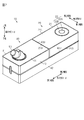
- the perspective view which shows the 1st unit and the 2nd unit of a CPAP apparatus The perspective view which shows the 1st unit and the 2nd unit of the CPAP apparatus in the 1st use state.
- a perspective view of the CPAP device viewed from a different angle from FIG. A partial cross-sectional view showing a connection portion between the first unit and the second unit.
- the CPAP device 10 includes a main body unit 20 as a first unit and a base unit 40 as a second unit. Further, as shown in FIG. 3, the main body unit 20 includes a blower 31 as a main component.
- the base unit 40 includes a second silencer 51 and a humidifier 52 as main components.
- the main body unit 20 is removable from the base unit 40.
- the CPAP device 10 is configured to be usable in the first use state and the second use state.
- the first used state is a state in which the main body unit 20 is attached to the base unit 40 and used
- the second used state is a state in which the main body unit 20 is used without being attached to the base unit 40.
- the main body unit 20 and the base unit 40 are used as shown in FIG.
- the second used state only the main body unit 20 is used, and the base unit 40 is not used.
- the main body unit 20 includes a flat rectangular parallelepiped first housing 21. As shown in FIG. 4, a blower 31 and the like are built in the first housing 21.
- the thickness direction of the first housing 21 is defined as the height direction Td, as shown in FIG.
- the long side direction of the first housing 21 is the length direction Ld
- the short side direction is the width direction Wd.
- an operation unit 22 for operating the main body unit 20 is provided on the upper side surface 21U of the first housing 21.
- the operation unit 22 is composed of a circular switch 22A and an annular switch 22B arranged so as to surround the switch 22A.
- the switches 22A and 22B are both push button switches, and by operating them, it is possible to turn on / off the power supply of the main unit 20 and change the settings.
- the first introduction port 23 for introducing air from the outside to the inside of the first housing 21 opens.
- a filter 24 for filtering dust and the like contained in the air introduced into the first housing 21 is attached to the first introduction port 23.
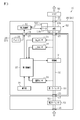
- a main flow path 32 through which air flows is partitioned inside the first housing 21 of the main unit 20.
- the upstream end of the main flow path 32 is connected to the first introduction port 23.
- a blower 31 that sends air from the first introduction port 23 to the downstream side is attached in the middle of the main flow path 32.
- the blower 31 is, for example, a centrifugal fan.
- a first silencer 33 is attached between the first introduction port 23 and the blower 31. The first silencer 33 attenuates the flow noise of the air flowing through the main flow path 32 as the blower 31 is driven.
- a pressure sensor 34 that detects the pressure of air on the downstream side of the blower 31 in the main flow path 32 is attached. Further, inside the first housing 21, a flow rate sensor 35 that detects the flow rate of air on the downstream side of the blower 31 in the main flow path 32 is attached. Further, a temperature sensor 36 that detects the temperature of the air flowing through the main flow path 32 is mounted inside the first housing 21. A first lead-out unit 25 for leading out air from the inside to the outside of the first housing 21 is connected to the downstream end of the main flow path 32.
- the first out-licensing unit 25 projects from the first end surface 21A of the first housing 21.
- the first out-licensing unit 25 is arranged side by side with respect to the first introduction port 23 in the width direction Wd of the first housing 21.
- the first lead-out portion 25 has a cylindrical shape as a whole, and protrudes from the first end surface 21A along the length direction Ld.
- the internal space of the first lead-out unit 25 communicates with the main flow path 32 inside the first housing 21.
- the first lead-out portion 25 can be roughly divided into a small diameter portion 25A, a large diameter portion 25B, and a thin wall portion 25C in order from the first end surface 21A side.
- the inner diameter of the large diameter portion 25B is the same as the inner diameter of the small diameter portion 25A, while the outer diameter of the large diameter portion 25B is larger than the outer diameter of the small diameter portion 25A.
- the outer peripheral surface of the small diameter portion 25A is recessed inward in the radial direction with respect to the outer peripheral surface of the large diameter portion 25B.
- the inner diameter of the thin wall portion 25C is larger than the inner diameter of the large diameter portion 25B.
- a step is formed at the boundary between the inner peripheral surface of the thin wall portion 25C and the inner peripheral surface of the large diameter portion 25B.
- the first connector 27 for electrically connecting the main body unit 20 and the base unit 40 is recessed.
- the first connector 27 is a so-called female connector, and a plurality of terminals are provided inside.
- the first connector 27 is arranged below the first lead-out unit 25.
- the main body unit 20 is provided with a first control unit 37 for controlling the operation of the blower 31.
- the first control unit 37 is electrically connected to the first connector 27 by a wiring (not shown).
- the first control unit 37 is 1) one or more processors that execute various processes according to a computer program (software), 2) an integrated circuit (ASIC) for a specific application, etc. that executes at least a part of the various processes. It can be configured as a circuitry including one or more dedicated hardware circuits of the above, or 3) a combination thereof.
- the processor includes a CPU and a memory such as a RAM and a ROM, and the memory stores a program code or an instruction configured to cause the CPU to execute a process.
- Memory or computer-readable media includes any available medium accessible by a general purpose or dedicated computer.
- the battery 38 is a rechargeable secondary battery, and is charged by connecting a charging cable (not shown) to the main unit 20.
- the battery 38 is also electrically connected to the first connector 27.
- a signal indicating an operation from the operation unit 22 is input to the first control unit 37.
- the pressure value detected by the pressure sensor 34 is input to the first control unit 37.
- the flow rate value detected by the flow rate sensor 35 is input to the first control unit 37.
- the temperature value detected by the temperature sensor 36 is input to the first control unit 37.
- the first control unit 37 is configured to increase or decrease the rotation speed of the blower 31 and control the amount of air sent out by controlling feedback control, feedforward control, etc., based on these input values.
- the first control unit 37 determines the exhalation state of the user based on the values detected by the pressure sensor 34 and the flow rate sensor 35, and the pressure value of the air supplied to the user so as to synchronize with the exhalation state. To control. Further, the first control unit 37 controls the power supply from the battery 38 to the first connector 27.
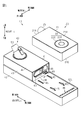
- the base unit 40 includes a second housing 41 having an L-shaped side view.
- the second housing 41 is roughly classified into a flat rectangular parallelepiped base housing 42 and a flat rectangular parallelepiped protruding housing 43 located above the base housing 42.
- the lengthwise dimension of the base housing 42 is larger than the lengthwise Ld dimension of the first housing 21.
- the dimensions of the base housing 42 in the lateral direction are the same as the dimensions of the width direction Wd of the first housing 21.
- the longitudinal direction of the base housing 42 of the second housing 41 is along the length direction Ld of the first housing 21, and the lateral direction of the base housing 42 is the first housing 21. It is assumed that it is along the width direction Wd of.
- the protruding housing 43 protrudes from the upper surface of the base housing 42 on the first end side in the length direction Ld.
- the end of the projecting housing 43 on the first end side in the length direction Ld coincides with the end of the base housing 42 on the first end side in the length direction Ld.
- the dimension of the height direction Td in the protruding housing 43 is substantially the same as the dimension of the height direction Td in the first housing 21.
- the size of the width direction Wd in the protruding housing 43 is substantially the same as the size of the width direction Wd in the first housing 21.
- the dimension of the length direction Ld in the protruding housing 43 is a value obtained by subtracting the dimension of the length direction Ld in the first housing 21 from the dimension in the longitudinal direction of the base housing 42.
- Both the base housing 42 and the protruding housing 43 have a box shape having a cavity inside. Further, the internal space of the base housing 42 and the internal space of the protruding housing 43 are continuous.
- the wall portion of the projecting housing 43 opposite to the base housing 42, that is, the upper wall portion is configured as a lid 44 that can be opened and closed.
- the lid 44 is adapted to rotate about the side on the first end side in the length direction Ld as the rotation center. When the lid 44 of the protruding housing 43 is rotated and opened, a part of the internal space of the protruding housing 43 and a part of the internal space of the base housing 42 are exposed.
- the upper side surface 42U of the base housing 42 is provided with a protrusion 45 protruding upward in the height direction Td of the base housing 42.
- two protrusions 45 are provided per row along the length direction Ld of the base housing 42.
- Two rows of protrusions 45 are provided in the width direction Wd of the base housing 42. That is, a total of four protrusions 45 are provided.
- a second introduction port 46 for introducing air from the outside to the inside of the base housing 42 is open.
- a plurality of second introduction ports 46 are provided.
- the plurality of second introduction ports 46 are arranged so as to line up over substantially the entire width direction Wd in the base housing 42. Further, each of the second introduction ports 46 is arranged near the edge on the second end side in the length direction Ld of the upper side surface 42U of the base housing 42.
- the upper side surface 42U of the base housing 42 functions as a surface on which the main body unit 20 is placed.
- an upstream flow path 53 through which air sucked into the blower 31 of the main body unit 20 flows is partitioned inside the second housing 41 of the base unit 40.
- the upstream end of the upstream flow path 53 is connected to the second introduction port 46.
- a second silencer 51 is attached in the middle of the upstream flow path 53.
- the second silencer 51 attenuates the flow noise of the air flowing through the upstream flow path 53.
- the volume of the second silencer 51 is larger than the volume of the second silencer 51 of the main unit 20, and the sound attenuation effect is higher than that of the first silencer 33 of the main unit 20.
- the downstream end of the upstream side flow path 53 is connected to a second outlet 47 for deriving air from the inside to the outside of the second housing 41.
- the second outlet 47 is a surface of the end faces on both sides of the protruding housing 43 in the length direction Ld, which is connected to the upper side surface 42U of the base housing 42, that is, the protruding housing.
- the opening shape of the second outlet 47 is the same as the opening shape of the first introduction port 23 of the main unit 20.
- a downstream flow path 54 through which air sent from the blower 31 of the main unit 20 flows is partitioned inside the second housing 41 of the base unit 40.
- a humidifier 52 is attached in the middle of the downstream flow path 54.
- the humidifier 52 includes a container 52A, a heater 52B, and a heater temperature sensor 52C.
- the container 52A is configured to be detachable from the second housing 41, and water can be stored inside.
- the air introduced into the humidifier 52 is led out from the humidifier 52 through the container 52A, so that the air is humidified.
- the heater 52B heats the water in the container 52A.
- the heater temperature sensor 52C detects the temperature of the heater 52B.
- the container 52A of the humidifier 52 can be attached and detached by opening the lid 44 of the protruding housing 43 in the second housing 41.
- a third introduction port 48 for introducing air from the outside to the inside of the protruding housing 43 is opened in the second end surface 43B of the protruding housing 43 in the base unit 40.
- the third introduction port 48 is arranged side by side in the width direction Wd of the protruding housing 43 with respect to the second outlet port 47.
- the third introduction port 48 has a circular shape in a plan view, and the outer diameter of the third introduction port 48 is larger than the outer diameter of the first lead-out portion 25 in the first housing 21.
- the second connector 49 for electrically connecting the main body unit 20 and the base unit 40 protrudes.
- the second connector 49 is a so-called male connector corresponding to the shape of the first connector 27 described above, and is provided with a plurality of terminals inside.
- the second connector 49 is arranged below the third introduction port 48.
- the central axis of the third lead-out unit 50 is inclined with respect to the height direction Td of the protruding housing 43.
- the internal space of the third lead-out unit 50 communicates with the downstream flow path 54.
- the base unit 40 is provided with a second control unit 56 that controls the operation of the heater 52B.
- the second control unit 56 includes 1) one or more processors that execute various processes according to a computer program (software), and 2) an integrated circuit (ASIC) for a specific application that executes at least a part of the various processes. It can be configured as a circuitry including one or more dedicated hardware circuits of the above, or 3) a combination thereof.
- the processor includes a CPU and a memory such as a RAM and a ROM, and the memory stores a program code or an instruction configured to cause the CPU to execute a process.
- Memory or computer-readable media includes any available medium accessible by a general purpose or dedicated computer.
- Power is supplied to the second control unit 56 from the battery 38 of the main unit 20 via the first connector 27 and the second connector 49 of the main unit 20. Further, a signal indicating the temperature value of air detected by the temperature sensor 36 from the first control unit 37 is input to the second control unit 56 via the first connector 27 and the second connector 49 of the main unit 20. ..
- the second control unit 56 sets the target heater temperature for heating the water in the container 52A based on the input air temperature value. For example, the second control unit 56 sets the target heater temperature by a predetermined calculation formula. Then, the second control unit 56 drives the heater 52B so that the heater temperature becomes the target heater temperature by control such as feedback control and feedforward control based on the heater temperature detected by the heater temperature sensor 52C. It is configured as follows. The second control unit 56 adjusts the water temperature in the container 52A by the heater 52B. Then, when the heater temperature reaches the target heater temperature, the second control unit 56 controls the heater 52B so as to keep the heater temperature at the target heater temperature.
- a rubber sealing member 60 is fixed to the second end surface 43B of the protruding housing 43 of the base unit 40.
- the sealing member 60 is formed along the opening edge of the second outlet 47 and has an annular shape that surrounds the second outlet 47 from the outside. Further, the sealing member 60 extends from the second end surface 43B toward the second end side in the length direction Ld as a whole.
- the base unit 40 is a fixed side unit on the side where the sealing member 60 is fixed, and the main body unit 20 is a mating side unit on which the sealing member 60 is not fixed. ..
- the opening shape at the tip edge on the second end side in the extending direction of the sealing member 60 allows the first introduction port 23 of the main body unit 20 to be attached when the main body unit 20 is mounted on the base unit 40. It has a shape that can be surrounded from the outside. Specifically, the opening shape at the tip edge on the second end side of the sealing member 60 in the length direction Ld is similar to the opening shape of the first introduction port 23 of the main body unit 20, and the opening area is large. ing.
- the sealing member 60 extends from the fixing portion 61 fixed to the second end surface 43B of the protruding housing 43 of the base unit 40 to the second end side in the length direction Ld. It is composed of a protrusion 62.
- the fixing portion 61 is fixed to the protruding housing 43 with an adhesive.
- the fixing portion of the fixing portion 61 to the second end surface 43B is the base end of the sealing member 60.
- the fixing portion 61 has an annular shape in which the thickness direction is larger than the extension direction. Further, the dimensions of the fixing portion 61 in the thickness direction are uniform.
- the thickness direction of the sealing member 60 is the dimension from the inner peripheral edge to the outer peripheral edge in the direction orthogonal to the opening surface of the sealing member 60, and is the maximum thickness of the sealing member 60. That is, the thickness direction dimension of the sealing member 60 is the thickness direction dimension of the fixing portion 61 in the present embodiment.
- the protruding portion 62 extends from the surface of the fixed portion 61 on the second end side in the length direction Ld.
- the thickness direction of the protruding portion 62 is smaller than the thickness direction of the fixing portion 61.
- the dimension in the extending direction of the protruding portion 62 is larger than the dimension in the thickness direction of the fixing portion 61. Therefore, the protruding portion 62 can be deformed in a direction orthogonal to the extending direction.
- the shape of the protruding portion 62 is tapered so that the opening area gradually decreases from the tip in the extending direction toward the base end.
- the protruding portion 62 has a shape that warps outward toward the tip end side in the extending direction.
- the opening area at the tip edge in the extending direction of the sealing member 60 is larger than the opening area at the proximal end in the extending direction of the sealing member 60.
- the dimension of the sealing member 60 in the extending direction is uniform in the present embodiment, and is 2.0 times the dimension of the sealing member 60 in the thickness direction.
- a filter 24 is attached to the first introduction port 23. More specifically, the recessed portion 21B is recessed in the first end surface 21A of the main body unit 20. Then, the first introduction port 23 is opened in the recessed surface 21C which is the bottom surface of the recessed portion 21B. When viewed in a plan view, the filter 24 is slightly larger than the opening area of the first introduction port 23, but smaller than the opening area of the recessed portion 21B. The outer edge portion of the filter 24 is attached to the recessed surface 21C of the recessed portion 21B. When the filter 24 is attached to the first introduction port 23, the outer edge of the filter 24 is separated from the outer edge of the recess 21B. As a result, a groove 70 recessed with respect to the first end surface 21A is formed between the outer edge of the filter 24 and the outer edge of the recessed portion 21B.
- the outer peripheral surface of the recessed portion 21B that is, the outer peripheral surface 71 of the groove 70 functions as a stopper surface.
- the outer peripheral surface 71 of the groove 70 faces the first introduction port 23 side of the main body unit 20.
- the outer peripheral surface 71 surrounds the second outlet 47 of the base unit 40 from the outside when viewed from Ld in the length direction. That is, the outer peripheral surface 71 of the groove 70 extends in a direction intersecting the opening surface of the first introduction port 23.
- the shortest distance D from the base end in the extending direction of the sealing member 60 to the main body unit 20 is the sealing member with respect to the base unit 40. It is the shortest distance D between the fixed portion of 60 and the first end surface 21A of the first housing 21.
- the dimension of the sealing member 60 in the extending direction is larger than the shortest distance D.
- the shortest distance D is 1.5 mm
- the dimension of the sealing member 60 in the extending direction is 3.0 mm, which is twice the shortest distance D.
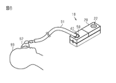
- the main body unit 20 is attached to the base unit 40. Specifically, as shown in FIG. 2, the main body unit 20 faces the base unit 40 so that the lower side surface 21D of the first housing 21 faces the upper side surface 42U of the base housing 42 of the second housing 41. It is placed above. Further, the first end surface 21A of the first housing 21 faces the second end surface 43B of the protruding housing 43 of the second housing 41 and is in contact with each other. Therefore, in the first use state, the CPAP device 10 has an elongated rectangular parallelepiped shape as a whole.
- the first introduction port 23 of the first housing 21 is connected to the second outlet 47 of the second housing 41, and these first introduction ports 23 and the first
- the upstream end of the main flow path 32 of the main body unit 20 is connected to the downstream end of the upstream side flow path 53 of the base unit 40 via the two outlets 47.
- the first lead-out unit 25 of the first housing 21 is inserted into the third introduction port 48 of the second housing 41, and the main body unit 20 is inserted through the first lead-out unit 25 and the third introduction port 48.
- the downstream end of the main flow path 32 is connected to the upstream end of the downstream side flow path 54 of the base unit 40.
- the first end portion of the air tube 91 is connected to the third lead-out portion 50 of the base unit 40, and the second end portion of the air tube 91 is connected to the mask 92. ..
- the mask 92 is worn, for example, to cover the nose or mouth of the user 93.
- the operation unit 22 of the main body unit 20 is operated, and when the power of the main body unit 20 is turned on, the blower 31 is driven.
- the protrusion 45 provided on the upper side surface 42U of the base housing 42 of the base unit 40 creates a gap between the lower side surface 21D of the first housing 21 and the second introduction port 46. Therefore, air is sucked into the CPAP device 10 from this gap through the second introduction port 46.
- the air sucked into the CPAP device 10 passes through the upstream flow path 53 of the second housing 41, the main flow path 32 of the first housing 21, and the downstream flow path 54 of the second housing 41, and is second. It is discharged to the outside from the third lead-out unit 50 of the housing 41. As a result, air is sent into the airway of the user 93 via the air tube 91 and the mask 92.
- the CPAP device 10 is used only by the main body unit 20, that is, the main body unit 20 is not mounted on the base unit 40.
- the first end portion of the air tube 91 is connected to the first lead-out portion 25 of the main body unit 20, and the second end portion of the air tube 91 is connected to the mask 92.
- the mask 92 is worn, for example, to cover the nose or mouth of the user 93.
- the blower 31 of the main body unit 20 when the blower 31 of the main body unit 20 is driven in the first use state, the main flow path 32 of the main body unit 20 is changed from the upstream side flow path 53 of the base unit 40. Due to the flow of air flowing into, the pressure in these channels becomes negative with respect to atmospheric pressure. Due to this negative pressure, the sealing member 60 is deformed so as to seal the gap between the main body unit 20 and the base unit 40. Therefore, when the blower 31 is being driven, it is possible to prevent air from leaking from between the main unit 20 and the base unit 40.
- the protruding portion 62 of the sealing member 60 has an opening area that expands in the extending direction. Therefore, when the main body unit 20 is attached to the base unit 40, it is possible to prevent the sealing member 60 from entering the inside of the first introduction port 23 of the main body unit 20, and the first introduction port 23 of the main body unit 20 is outside. It is easy to realize a configuration that surrounds from.
- the tip of the protrusion 62 of the sealing member 60 in the extending direction is accommodated in the groove 70 before the blower 31 is driven. Therefore, the tip of the protrusion 62 in the extending direction is easily positioned at an appropriate position. Therefore, when the main body unit 20 is attached to the base unit 40, it is unlikely that the tip end side of the protruding portion 62 will spread excessively to the outside and the airtightness cannot be ensured.
- the sealing member 60 is fixed to the base unit 40. That is, in the second use state, the sealing member 60 is not arranged around the first introduction port 23 of the main body unit 20. Therefore, the sealing member 60 will not be soiled when the main body unit 20 is carried assuming use in the second used state.
- the dimension of the sealing member 60 is 2.0 times the dimension in the extending direction of the sealing member 60 in the thickness direction of the sealing member 60. If the dimension of the sealing member 60 in the extending direction is excessively long, when the main body unit 20 is attached to the base unit 40, unintended deformation such as folding in a bellows shape occurs, and the sealing member 60 becomes It may not adhere properly to the base unit 40. If the dimensions of the sealing member 60 are in the extending direction as in the above embodiment, it is unlikely that unintended deformation will occur, and appropriate sealing by the sealing member 60 will be realized.
- the material of the sealing member 60 including the protruding portion 62 is made of rubber and folded, and the protruding portion 62 is elastically deformed. Therefore, in the first use state, the sealing member 60 is easily deformed by the negative pressure generated by driving the blower 31.
- the configuration of the main unit 20 is not limited to the example of the above embodiment.
- a humidifier may be provided in the main body unit 20.
- the configuration of the base unit 40 is not limited to the example of the above embodiment.
- the downstream flow path 54 and the humidifier 52 may be omitted.
- a function of adding an aroma or a medicinal ingredient may be added to the humidifier 52 of the base unit 40.
- the base unit 40 may be one in which the upstream flow path 53 through which the air sucked into the blower 31 flows is partitioned.
- the shapes of the first introduction port 23 of the main unit 20 and the second outlet 47 of the base unit 40 are not limited to the examples of the above embodiment.
- the first introduction port 23 may have a circular shape in a plan view
- the second outlet 47 may have a square shape in a plan view. Even if the shape of the first introduction port 23 and the shape of the second outlet 47 are not the same as described above, if the first introduction port 23 can be surrounded from the outside by the tip of the sealing member 60 in the extending direction. I do not care.
- the positional relationship between the first introduction port 23 of the main unit 20 and the second outlet 47 of the base unit 40 is not limited to the example of the above embodiment.
- the positions of the first inlet 23 and the second outlet 47 do not have to match when viewed from Ld in the length direction.
- the size of the opening at the tip edge in the extending direction of the sealing member 60 may be appropriately increased so that the first introduction port 23 can be surrounded from the outside.
- the sealing member 60 may extend obliquely toward the first introduction port 23.
- the shape of the sealing member 60 is not limited to the example of the above embodiment.
- the fixing portion 61 may be omitted.
- the end of the protrusion 62 on the base unit 40 side may be fixed to the second end surface 43B of the protrusion housing 43 with an adhesive.
- the opening area of the protruding portion 62 constituting the sealing member 60 decreases from the tip end in the extending direction toward the proximal end side over the entire extending direction of the sealing member 60. Further, the opening area may be the same over the entire extending direction of the sealing member 60.
- the shape may be such that the second outlet 47 is circularly enclosed from the outside and the first introduction port 23 can be enclosed from the outside.
- the dimension of the sealing member 60 in the extending direction is not limited to the example of the above embodiment.
- the dimension in the extending direction of the sealing member 60 is 1.5 times or more and less than 6.0 times the dimension in the thickness direction of the sealing member 60, the sealing member 60 is easily deformed by negative pressure. It is suitable from the viewpoint of the balance between the main body unit 20 and the suppression of unintended deformation of the sealing member 60 when the main unit 20 is attached to the base unit 40.
- the material of the sealing member 60 is not limited to the example of the above embodiment.
- the material of the sealing member 60 may be an elastomer. In this case, it is easy to realize the deformation of the sealing member 60 as in the example of the above embodiment.
- the material of the sealing member 60 may be the same as the material of the first housing 21 and the second housing 41. Even in this case, if the dimension of the sealing member 60 in the thickness direction is correspondingly small, the sealing member 60 can be deformed by the negative pressure accompanying the driving of the blower 31.
- the material of the sealing member 60 may be appropriately selected according to the shape of the sealing member 60 and the strength of the negative pressure generated by driving the blower 31.
- the fixing location of the sealing member 60 is not limited to the example of the above embodiment.
- the sealing member 60 may be fixed to the main body unit 20.
- the main body unit 20 is a fixed side unit to which the sealing member 60 is fixed
- the base unit 40 is a mating side unit to which the sealing member 60 is not fixed.
- the configuration of the groove 70 in the first end surface 21A of the main body unit 20 is not limited to the example of the above embodiment.
- the groove 70 may not be formed by the filter 24 and the recessed portion 21B, but may be a groove recessed in the first end surface 21A.
- the surface of the groove 70 on the center side of the first introduction port 23 may be inclined so as to be located closer to the center side of the first introduction port 23 toward the second outlet port 47 side. In this case, if the protruding portion 62 of the sealing member 60 has a wider opening area toward the tip end side in the extending direction, surface contact is likely to occur.
- the stopper surface does not have to be configured as a partial outer peripheral surface 71 of the groove 70.
- the filter 24 may not be provided.
- the outer peripheral surface of the recessed portion 21B functions as a stopper surface.
- the first lead-out unit 25 of the main body unit 20 is inserted into the third introduction port 48 of the base unit 40, but this unevenness relationship may be reversed. That is, the main body unit 20 may be provided with a configuration corresponding to the third introduction port 48, and the base unit 40 may be provided with a configuration corresponding to the first lead-out unit 25.
- the base unit 40 may also be provided with a battery. Further, when a battery is provided in the base unit 40, when the main body unit 20 is attached to the base unit 40, the battery of the main body unit 20 is changed from the battery of the base unit 40 via the second connector 49 and the first connector 27. It may be possible to supply power to 38.
- the sealing member 60 may be configured as, for example, a lip seal.
- the protrusion 62 of the sealing member 60 may be configured as an annular or looped lip.
- the extending direction of the sealing member 60 may be referred to as the protruding direction of the protruding portion 62 of the sealing member 60.
- the extending direction of the sealing member 60 may be parallel to or coincide with the air flow direction at the connection point between the main flow path 32 of the main body unit 20 and the upstream side flow path 53 of the base unit 40.
- the direction of air flow at the connection may be parallel to or coincide with the length direction Ld.
- 10 ... CPAP device, 20 ... Main unit, 21 ... First housing, 21A ... First end surface, 21B ... Recessed part, 21C ... Recessed surface, 21D ... Lower side surface, 21U ... Upper side surface, 22 ... Operation unit, 22A ... Switch, 22B ... Switch, 23 ... 1st introduction port, 24 ... Filter, 25 ... 1st lead-out part, 25A ... Small diameter part, 25B ... Large diameter part, 25C ... Thin wall part, 27 ... 1st connector, 31 ... Blower , 32 ... main flow path, 33 ... first silencer, 34 ... pressure sensor, 35 ... flow sensor, 36 ... temperature sensor, 37 ... first control unit, 38 ...
- battery 40 ... base unit, 41 ... second housing, 42 ... base housing, 42U ... upper side surface, 43 ... protruding housing, 43B ... second end surface, 44 ... lid, 45 ... protrusion, 46 ... second introduction port, 47 ... second outlet, 48 ... third introduction Port, 49 ... 2nd connector, 50 ... 3rd outlet, 51 ... 2nd silencer, 52 ... humidifier, 52A ... container, 52B ... heater, 52C ... heater temperature sensor, 53 ... upstream flow path, 54 ... downstream Side flow path, 56 ... second control unit, 60 ... sealing member, 61 ... fixed part, 62 ... protruding part, 70 ... groove, 71 ... outer peripheral surface, 91 ... air tube, 92 ... mask, 93 ... user, D ... Shortest distance.
Landscapes
- Health & Medical Sciences (AREA)
- Emergency Medicine (AREA)
- Pulmonology (AREA)
- Engineering & Computer Science (AREA)
- Anesthesiology (AREA)
- Biomedical Technology (AREA)
- Heart & Thoracic Surgery (AREA)
- Hematology (AREA)
- Life Sciences & Earth Sciences (AREA)
- Animal Behavior & Ethology (AREA)
- General Health & Medical Sciences (AREA)
- Public Health (AREA)
- Veterinary Medicine (AREA)
- Structures Of Non-Positive Displacement Pumps (AREA)
Priority Applications (2)
| Application Number | Priority Date | Filing Date | Title |
|---|---|---|---|
| JP2021537587A JP7160207B2 (ja) | 2019-08-08 | 2020-05-20 | Cpap装置 |
| US17/650,138 US12364836B2 (en) | 2019-08-08 | 2022-02-07 | CPAP device with sealing member between two detachable units |
Applications Claiming Priority (2)
| Application Number | Priority Date | Filing Date | Title |
|---|---|---|---|
| JP2019146197 | 2019-08-08 | ||
| JP2019-146197 | 2019-08-08 |
Related Child Applications (1)
| Application Number | Title | Priority Date | Filing Date |
|---|---|---|---|
| US17/650,138 Continuation US12364836B2 (en) | 2019-08-08 | 2022-02-07 | CPAP device with sealing member between two detachable units |
Publications (1)
| Publication Number | Publication Date |
|---|---|
| WO2021024573A1 true WO2021024573A1 (ja) | 2021-02-11 |
Family
ID=74503387
Family Applications (1)
| Application Number | Title | Priority Date | Filing Date |
|---|---|---|---|
| PCT/JP2020/019895 Ceased WO2021024573A1 (ja) | 2019-08-08 | 2020-05-20 | Cpap装置 |
Country Status (3)
| Country | Link |
|---|---|
| US (1) | US12364836B2 (enExample) |
| JP (1) | JP7160207B2 (enExample) |
| WO (1) | WO2021024573A1 (enExample) |
Citations (4)
| Publication number | Priority date | Publication date | Assignee | Title |
|---|---|---|---|---|
| JPH0612244U (ja) * | 1992-07-23 | 1994-02-15 | 日信工業株式会社 | マスタシリンダ用リザーバのグロメットシール |
| JPH0813594A (ja) * | 1994-06-29 | 1996-01-16 | Inax Corp | 衛生器具の排水管への接続構造 |
| JP2004345715A (ja) * | 2003-05-26 | 2004-12-09 | Tdk Corp | 製品収容容器用パージシステム |
| JP2009508647A (ja) * | 2005-09-23 | 2009-03-05 | アールアイシー・インベストメンツ・エルエルシー | モジュール式圧力支援装置 |
Family Cites Families (15)
| Publication number | Priority date | Publication date | Assignee | Title |
|---|---|---|---|---|
| US3064853A (en) * | 1959-12-30 | 1962-11-20 | Mitchell Co John E | Seal |
| US3275344A (en) * | 1965-02-19 | 1966-09-27 | Gen Electric | Misalignment compensating coupling |
| AT536U1 (de) * | 1994-11-15 | 1995-12-27 | Hutterer & Lechner Kg | Unterputzsifon |
| US20040237244A1 (en) | 2003-05-26 | 2004-12-02 | Tdk Corporation | Purge system for product container and interface seal used in the system |
| US7152597B2 (en) * | 2003-09-25 | 2006-12-26 | Datex-Ohmeda, Inc. | Breathing circuit adapter |
| US8544465B2 (en) * | 2005-08-15 | 2013-10-01 | Redmed Limited | Compliant coupling or adaptor |
| US7726309B2 (en) * | 2006-06-05 | 2010-06-01 | Ric Investments, Llc | Flexible connector |
| DE102007050853B3 (de) * | 2007-10-24 | 2009-05-07 | Dräger Medical AG & Co. KG | Einmalabsorber mit Adapter und Lippendichtung |
| US9844636B2 (en) | 2009-02-13 | 2017-12-19 | Koninklijke Philips N.V. | Pressure support device user interface |
| US10213573B2 (en) * | 2011-12-22 | 2019-02-26 | Resmed Limited | Humidifiers for respiratory apparatus |
| JP6143508B2 (ja) * | 2013-03-19 | 2017-06-07 | 日本電産コパル電子株式会社 | Cpap装置 |
| WO2016141430A1 (en) * | 2015-03-10 | 2016-09-15 | Resmed Limited | Fluid connector with face seal |
| WO2016150373A1 (zh) * | 2015-03-24 | 2016-09-29 | 湖南明康中锦医疗科技发展有限公司 | 一种便携式呼吸机 |
| CN105597208B (zh) * | 2016-01-26 | 2019-01-04 | 北京怡和嘉业医疗科技股份有限公司 | 一种呼吸机 |
| WO2020083359A1 (zh) * | 2018-10-26 | 2020-04-30 | 天津怡和嘉业医疗科技有限公司 | 用于通气治疗设备的水箱安装结构以及通气治疗设备 |
-
2020
- 2020-05-20 WO PCT/JP2020/019895 patent/WO2021024573A1/ja not_active Ceased
- 2020-05-20 JP JP2021537587A patent/JP7160207B2/ja active Active
-
2022
- 2022-02-07 US US17/650,138 patent/US12364836B2/en active Active
Patent Citations (4)
| Publication number | Priority date | Publication date | Assignee | Title |
|---|---|---|---|---|
| JPH0612244U (ja) * | 1992-07-23 | 1994-02-15 | 日信工業株式会社 | マスタシリンダ用リザーバのグロメットシール |
| JPH0813594A (ja) * | 1994-06-29 | 1996-01-16 | Inax Corp | 衛生器具の排水管への接続構造 |
| JP2004345715A (ja) * | 2003-05-26 | 2004-12-09 | Tdk Corp | 製品収容容器用パージシステム |
| JP2009508647A (ja) * | 2005-09-23 | 2009-03-05 | アールアイシー・インベストメンツ・エルエルシー | モジュール式圧力支援装置 |
Also Published As
| Publication number | Publication date |
|---|---|
| US20220152335A1 (en) | 2022-05-19 |
| JP7160207B2 (ja) | 2022-10-25 |
| JPWO2021024573A1 (enExample) | 2021-02-11 |
| US12364836B2 (en) | 2025-07-22 |
Similar Documents
| Publication | Publication Date | Title |
|---|---|---|
| US10322257B2 (en) | Humidifier assembly and method of providing moisture to supplied gas in a pressure support system | |
| JP6987639B2 (ja) | 顔面シールの付いた流体コネクター | |
| US7677246B2 (en) | Modular pressure support system | |
| CN102187545B (zh) | 医疗通气机中的电源控制 | |
| JP6814137B2 (ja) | 液体チャンバの切り離しシステム及び方法 | |
| JP2022190157A (ja) | Cpap装置 | |
| WO2014184377A2 (en) | Flow diffuser and sound cone | |
| CN113038984B (zh) | 压力支持系统的阀 | |
| JP2025060902A (ja) | 呼吸補助装置用の液体チャンバ | |
| CN110833647A (zh) | 患者接口装置和通气治疗设备 | |
| US20220218937A1 (en) | Humidifier | |
| JP7448079B2 (ja) | Cpap装置 | |
| US12296092B2 (en) | CPAP device | |
| JP2022506420A (ja) | 呼吸補助装置及び/又はそのコンポーネント | |
| WO2021024573A1 (ja) | Cpap装置 | |
| US12345442B2 (en) | Humidifier | |
| WO2018008423A1 (ja) | 圧力コントローラ | |
| US20200114099A1 (en) | Cpap device | |
| US12453835B2 (en) | Humidification device for a positive airway pressure breathing apparatus | |
| NZ750095A (en) | Respiratory pressure therapy system | |
| NZ750095B2 (en) | Respiratory pressure therapy system |
Legal Events
| Date | Code | Title | Description |
|---|---|---|---|
| 121 | Ep: the epo has been informed by wipo that ep was designated in this application |
Ref document number: 20849676 Country of ref document: EP Kind code of ref document: A1 |
|
| ENP | Entry into the national phase |
Ref document number: 2021537587 Country of ref document: JP Kind code of ref document: A |
|
| NENP | Non-entry into the national phase |
Ref country code: DE |
|
| 122 | Ep: pct application non-entry in european phase |
Ref document number: 20849676 Country of ref document: EP Kind code of ref document: A1 |