WO2021024429A1 - 補正制御装置、空気調和機、補正制御方法、および、補正制御プログラム - Google Patents
補正制御装置、空気調和機、補正制御方法、および、補正制御プログラム Download PDFInfo
- Publication number
- WO2021024429A1 WO2021024429A1 PCT/JP2019/031211 JP2019031211W WO2021024429A1 WO 2021024429 A1 WO2021024429 A1 WO 2021024429A1 JP 2019031211 W JP2019031211 W JP 2019031211W WO 2021024429 A1 WO2021024429 A1 WO 2021024429A1
- Authority
- WO
- WIPO (PCT)
- Prior art keywords
- air conditioner
- installation state
- correction control
- temperature
- living space
- Prior art date
- Legal status (The legal status is an assumption and is not a legal conclusion. Google has not performed a legal analysis and makes no representation as to the accuracy of the status listed.)
- Ceased
Links
Images





Classifications
-
- F—MECHANICAL ENGINEERING; LIGHTING; HEATING; WEAPONS; BLASTING
- F24—HEATING; RANGES; VENTILATING
- F24F—AIR-CONDITIONING; AIR-HUMIDIFICATION; VENTILATION; USE OF AIR CURRENTS FOR SCREENING
- F24F11/00—Control or safety arrangements
- F24F11/30—Control or safety arrangements for purposes related to the operation of the system, e.g. for safety or monitoring
-
- F—MECHANICAL ENGINEERING; LIGHTING; HEATING; WEAPONS; BLASTING
- F24—HEATING; RANGES; VENTILATING
- F24F—AIR-CONDITIONING; AIR-HUMIDIFICATION; VENTILATION; USE OF AIR CURRENTS FOR SCREENING
- F24F11/00—Control or safety arrangements
- F24F11/70—Control systems characterised by their outputs; Constructional details thereof
- F24F11/72—Control systems characterised by their outputs; Constructional details thereof for controlling the supply of treated air, e.g. its pressure
- F24F11/79—Control systems characterised by their outputs; Constructional details thereof for controlling the supply of treated air, e.g. its pressure for controlling the direction of the supplied air
Definitions
- the present invention relates to a correction control device, an air conditioner, a correction control method, and a correction control program.
- An air conditioner with optimized temperature control and airflow control in the living space may be installed under the floor or under the ceiling for air conditioning throughout the highly airtight and insulated house.
- An example of such an air conditioner is a room air conditioner for wall hanging (also referred to as wall hanging RAC).
- the temperature control is turned off and the operation is stopped when the target temperature is reached immediately after the air conditioner is started.
- the energy-saving operation is not carried out because the operation is repeatedly restarted and stopped.
- the energy-saving operation is not carried out because the correction amount of the high-precision sensing information mounted on the air conditioner is excessively used.
- Patent Document 1 discloses a highly airtight house in which a cooling device is installed behind the ceiling and a heating device is installed under the floor.
- the cooling device and heating device disclosed in Patent Document 1 require control exclusively for a highly airtight house. Such cooling and heating devices cannot be used in a normal living space because the controls dedicated to a highly airtight house do not correspond to a normal living space.
- an air conditioner for a normal living space is installed in a small space such as under the floor or under the ceiling, the temperature control will be turned off and the operation will stop when the target temperature is reached immediately after the air conditioner is started. is there.
- An object of the present invention is to prevent the operation from being stopped and to continue the energy-saving operation even when the air conditioner is placed in an abnormal installation state.
- the correction control device is a correction control device that controls the correction of the operation of the air conditioner installed in the building.
- a determination unit that determines whether the installation state of the air conditioner is a normal installation state or an abnormal installation state other than the normal installation state. When it is determined that the installation state of the air conditioner is the abnormal installation state, control is performed to control the air conditioner so that the operation of the air conditioner is not affected by the blowout temperature of the air conditioner. Equipped with a part.
- the determination unit determines whether the installation state of the air conditioner is a normal installation state or an abnormal installation state.
- the control unit controls the air conditioner so that the operation of the air conditioner is not affected by the blowout temperature of the air conditioner. According to the correction control device according to the present invention, even when the air conditioner is placed in an abnormal installation state, it is possible to prevent the operation from stopping and to continue the energy-saving operation.
- FIG. 1 An example of using an air conditioner provided with a correction control device according to the first embodiment.
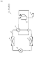
- the refrigerant circuit during the cooling operation of the air conditioner according to the first embodiment.
- the refrigerant circuit during the heating operation of the air conditioner according to the first embodiment.
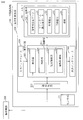
- the block diagram of the correction control device which concerns on Embodiment 1.
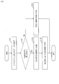
- FIG. 1 The flow chart which shows the operation of the correction control device which concerns on Embodiment 1.
- FIG. An example of normal heat distribution data and real-time heat distribution data according to the first embodiment.
- the block diagram of the correction control device which concerns on modification of embodiment.
- Embodiment 1 The configuration of the present embodiment will be described with reference to FIGS. 1 to 9.
- FIG. 1 is a diagram showing a usage example of an air conditioner 100 provided with a correction control device 200 according to the present embodiment.
- the air conditioner 100 provided with the correction control device 200 is installed in a building 40 such as a house in which the user 30 resides.
- the building 40 is, for example, a highly airtight and insulated house.
- FIG. 1 shows how one air conditioner 100 performs air conditioning in the entire building.
- the building 40 has a living space 41 in which the user 30 lives, and a non-living space 420 other than the living space 41 and communicating with the living space 41.
- the non-living space 420 is a space such as a narrow space 42, an attic 42a, or an underfloor 42b, which is a space narrower than the living space 41.
- the narrow space 42 provided behind the wall, narrower than the living space 41, and communicating with the living space 41 will be described as an example of the non-living space 420.
- the air conditioner 100 is installed in the living space 41 or the non-living space 420 in the building 40.
- the air conditioner 100 When the air conditioner 100 is installed in the living space 41, it means that the airflow from the air conditioner 100 is blown toward the living space 41. Further, the fact that the air conditioner 100 is installed in the non-living space 420 means a state in which the airflow from the air conditioner 100 is blown toward the non-living space 420.
- the state in which the air conditioner 100 is installed in the living space 41 is an example in which the installation state of the air conditioner 100 is a normal installation state. Further, the state in which the air conditioner 100 is installed in the non-living space 420 is an example in which the installation state of the air conditioner 100 is an abnormal installation state other than the normal installation state.
- the air conditioner 100 is installed in the living space 41 in the building 40 or the non-living space 420, that is, the narrow space 42. Further, the air conditioner 100 is equipped with a correction control device 200. In FIG. 1, the air conditioner 100 is installed in a narrow space 42. The correction control device 200 controls the correction of the operation of the air conditioner 100 installed in the building 40.
- the configuration of the air conditioner 100 will be described with reference to FIGS. 2 and 3.
- the air conditioner 100 uses a refrigeration cycle having a heat exchanger in which a refrigerant is compressed by a compressor, circulated, absorbed from a low temperature heat source, and exhausted to a high temperature heat source.
- FIG. 2 shows the refrigerant circuit 31 during the cooling operation.
- FIG. 3 shows the refrigerant circuit 31 during the heating operation.
- the air conditioner 100 includes a refrigerant circuit 31 in which a refrigerant circulates.
- the air conditioner 100 includes a compressor 32, a four-way valve 33, a first heat exchanger 34 which is an outdoor heat exchanger, an expansion mechanism 35 which is an expansion valve, and a second heat exchanger which is an indoor heat exchanger. 36 is further provided.
- the compressor 32, the four-way valve 33, the first heat exchanger 34, the expansion mechanism 35, and the second heat exchanger 36 are connected to the refrigerant circuit 31.
- the compressor 32 compresses the refrigerant.
- the four-way valve 33 switches the flow direction of the refrigerant between the cooling operation and the heating operation.
- the first heat exchanger 34 operates as a condenser during the cooling operation to dissipate heat from the refrigerant compressed by the compressor 32. That is, the first heat exchanger 34 exchanges heat using the refrigerant compressed by the compressor 32.
- the first heat exchanger 34 operates as an evaporator during the heating operation, and heats the refrigerant by exchanging heat between the outdoor air and the refrigerant expanded by the expansion mechanism 35.
- the expansion mechanism 35 expands the refrigerant radiated by the condenser.
- the second heat exchanger 36 operates as a condenser during the heating operation and dissipates heat from the refrigerant compressed by the compressor 32. That is, the second heat exchanger 36 performs heat exchange using the refrigerant compressed by the compressor 32.
- the second heat exchanger 36 operates as an evaporator during the cooling operation, and heats the refrigerant by exchanging heat between the indoor air and the refrigerant expanded by the expansion mechanism 35.
- the air conditioner 100 further includes a controller 37 that controls the refrigeration cycle.
- FIGS. 2 and 3 show only the connection between the controller 37 and the compressor 32, the controller 37 is connected not only to the compressor 32 but also to components other than the compressor 32 connected to the refrigerant circuit 31. You may.
- the controller 37 monitors and controls the state of each component connected to the controller 37.
- FIG. 4 is a diagram showing the configuration of the correction control device 200 according to the present embodiment.
- the correction control device 200 is mounted on the air conditioner 100.
- the air conditioner 100 includes a sensor unit 101.
- the sensor unit 101 is an infrared sensor for detecting the temperature of the space in which the air conditioner 100 is installed as the space temperature.
- the sensor unit 101 may be composed of a sensor that detects the temperature Ta on the front surface of the outlet of the air conditioner 100 and a sensor that detects the temperature Tb around the air conditioner 100.
- a sensor that detects the temperature Tb around the air conditioner 100 is provided, for example, on the side surface or the upper surface of the air conditioner 100.
- the correction control device 200 is a computer.
- the correction control device 200 includes a processor 910 and other hardware such as a memory 921, an input interface 930, an output interface 940, and a communication device 950.
- the processor 910 is connected to other hardware via a signal line and controls these other hardware.
- the correction control device 200 includes an auxiliary storage device.
- the correction control device 200 includes an acquisition unit 210, a determination unit 220, an airflow control unit 230, an operation control unit 240, and a storage unit 250 as functional elements.
- the airflow control unit 230 and the operation control unit 240 are also referred to as a control unit 20.
- the functions of the acquisition unit 210, the determination unit 220, the airflow control unit 230, and the operation control unit 240 are realized by software.
- the storage unit 250 is provided in the memory 921.
- the storage unit 250 stores normal heat distribution data 51, real-time heat distribution data 52, space temperature 53, target temperature 54, and threshold value 55.
- the operation control unit 240 is an example of the controller 37 of FIGS. 2 and 3.
- the processor 910 is a device that executes a correction control program.
- the correction control program is a program that realizes the functions of the acquisition unit 210, the determination unit 220, the airflow control unit 230, and the operation control unit 240.
- the processor 910 is an IC (Integrated Circuit) that performs arithmetic processing. Specific examples of the processor 910 are a CPU (Central Processing Unit), a DSP (Digital Signal Processor), and a GPU (Graphics Processing Unit).
- the memory 921 is a storage device that temporarily stores data.
- a specific example of the memory 921 is a SRAM (Static Random Access Memory) or a DRAM (Dynamic Random Access Memory).
- the auxiliary storage device is a storage device that stores data.
- a specific example of the auxiliary storage device is an HDD.
- the auxiliary storage device may be a portable storage medium such as an SD (registered trademark) memory card, CF, NAND flash, a flexible disk, an optical disk, a compact disc, a Blu-ray (registered trademark) disk, or a DVD.
- HDD is an abbreviation for Hard Disk Drive.
- SD® is an abbreviation for Secure Digital.
- CF is an abbreviation for CompactFlash®.
- DVD is an abbreviation for Digital Versaille Disc.
- the input interface 930 is a port connected to an input device such as a mouse, keyboard, or touch panel. Specifically, the input interface 930 is a USB (Universal Serial Bus) terminal. The input interface 930 may be a port connected to a LAN (Local Area Network).
- the output interface 940 is a port to which a cable of an output device such as a display is connected. Specifically, the output interface 940 is a USB terminal or an HDMI (registered trademark) (High Definition Multimedia Interface) terminal. Specifically, the display is an LCD (Liquid Crystal Display).
- the communication device 950 has a receiver and a transmitter.
- the communication device 950 is connected to a communication network such as a LAN, the Internet, or a telephone line.
- the communication device 950 is a communication chip or a NIC (Network Interface Card). Further, the communication device 950 receives an operation signal from the operation device 300 used by the user 30.
- the correction control program is executed in the correction control device 200.
- the correction control program is read into the processor 910 and executed by the processor 910.
- the memory 921 not only the correction control program but also the OS (Operating System) is stored.
- the processor 910 executes the correction control program while executing the OS.
- the correction control program and the OS may be stored in the auxiliary storage device.
- the correction control program and the OS stored in the auxiliary storage device are loaded into the memory 921 and executed by the processor 910. A part or all of the correction control program may be incorporated in the OS.
- the correction control device 200 may include a plurality of processors that replace the processor 910. These plurality of processors share the execution of the correction control program.
- Each processor like the processor 910, is a device that executes a correction control program.
- Data, information, signal values and variable values used, processed or output by the correction control program are stored in the memory 921, the auxiliary storage device, or the register or cache memory in the processor 910.
- the "part" of each part of the correction control device 200 may be read as “process”, “procedure” or “process”. Further, the "process” in which the "part” of each part of the correction control device 200 is replaced with the "program", the “program product”, the "computer-readable storage medium in which the program is stored", or the "program is recorded”. It may be read as "a computer-readable recording medium”.
- the correction control program causes the computer to execute each process, each procedure or each process in which the "part” of each of the above parts is read as “process", “procedure” or “process”.
- the correction control method is a method performed by each device of the correction control device 200 executing a correction control program.
- the correction control program may be provided stored in a computer-readable recording medium. Further, the correction control program may be provided as a program product.
- the determination unit 220 determines whether the installation state of the air conditioner 100 is a normal installation state or an abnormal installation state other than the normal installation state. Specifically, the determination unit 220 determines whether the air conditioner 100 is installed in the living space 41 or the non-living space 420.
- control unit 20 determines that the installation state of the air conditioner 100 is an abnormal installation state
- the control unit 20 prevents the operation of the air conditioner 100 from being affected by the blowout temperature of the air conditioner 100. To control. That is, when the control unit 20 determines that the installation state of the air conditioner 100 is an abnormal installation state, the air conditioner 100 prevents the operation stop control of the air conditioner 100 by stopping the temperature control function. To control.
- control unit 20 determines that the air conditioner 100 is installed in the non-living space 420, the operation of the air conditioner 100 is not affected by the blowout temperature of the air conditioner 100. Controls the air conditioner 100. More specifically, it is as follows.
- the heat distribution data when the installation state of the air conditioner 100 is the normal installation state is stored as the normal heat distribution data 51. That is, the heat distribution data in the living space 41 when the air conditioner 100 installed in the living space 41 is operated is stored as the normal heat distribution data 51.
- the normal heat distribution data 51 is information possessed by the manufacturer of the air conditioner 100.
- the normal heat distribution data 51 is stored in the storage unit 250 in advance at the time of shipment of the air conditioner 100.
- the normal heat distribution data 51 is a thermal image in which the temperature of the central portion is high and the temperature gradually decreases as the distance from the center increases.
- step S101 the acquisition unit 210 acquires real-time heat distribution data when the air conditioner 100 is being operated as real-time heat distribution data 52. Specifically, the acquisition unit 210 generates real-time heat distribution data 52 by using the sensor data from the sensor unit 101 of the air conditioner 100. Then, the acquisition unit 210 stores the real-time heat distribution data 52 in the storage unit 250.
- step S102 the determination unit 220 determines whether the air conditioner 100 is installed in the living space 41 or the narrow space 42 based on the normal heat distribution data 51 and the real-time heat distribution data 52.
- FIG. 6 is a diagram showing an example of real-time heat distribution data 52 in the living space 41 and real-time heat distribution data 52 in the narrow space 42 according to the present embodiment.
- the air conditioner 100 acquires a thermal image that matches the distribution of heat airflow that has reached the floor surface.
- the real-time heat distribution data 52 becomes a thermal image as shown in the upper part of FIG. That is, the real-time heat distribution data 52 in the living space 41 is a thermal image in which the temperature of the central portion is high and the temperature gradually decreases as the distance from the center increases.
- the thermal image is as shown in the lower part of FIG. That is, the real-time heat distribution data 52 in the narrow space 42 becomes a thermal image in which the entire temperature becomes high.
- the determination unit 220 calculates, for example, the degree of similarity between the normal heat distribution data 51 and the real-time heat distribution data 52, and determines that the installation location is the living space 41 when the degree of similarity exceeds a predetermined value. Further, the determination unit 220 determines that the installation location is the narrow space 42 when the similarity is equal to or less than a predetermined value. Alternatively, the determination unit 220 may determine whether or not the installation location is a narrow space 42 only from the distribution of the high temperature area in the real-time heat distribution data 52. For example, in the real-time heat distribution data 52, when 95% or more is a high temperature area, the determination unit 220 may determine that the installation location is a narrow space 42.
- step S103 If it is determined that the installation location is the living space 41, the process proceeds to step S103. If it is determined that the installation location is the narrow space 42, the process proceeds to step S104.
- step S103 the operation control unit 240 controls the operation of the air conditioner 100 based on the space temperature 53 and the target temperature 54.
- the space temperature 53 is the temperature of the space in which the air conditioner 100 is installed when the air conditioner 100 is operated.
- the space temperature 53 is set based on the sensor data from the sensor unit 101.
- the target temperature 54 is a temperature preset by the user 30.
- the target temperature 54 is a set temperature set by the user 30 using the operating device 300.
- the operation control unit 240 is based on the temperature Ta in front of the outlet of the air conditioner 100 and the temperature Tb around the air conditioner 100.
- the temperature obtained is defined as the space temperature 53.
- the temperature Ta on the front surface of the air outlet of the air conditioner 100 is mainly the temperature of the floor surface or the like in front of the air conditioner 100.
- the operation control unit 240 may set the average value of the temperature Ta of the floor surface in front of the outlet of the air conditioner 100 and the temperature Tb around the air conditioner 100 as the space temperature 53.
- the operation control unit 240 Based on the space temperature 53 and the target temperature 54, the operation control unit 240 performs normal operation control so that the space temperature 53 of the air conditioner 100 becomes the target temperature 54.
- step S104 the airflow control unit 230 prevents the operation control of the air conditioner 100 from being affected by the blowout temperature of the air conditioner 100.
- the airflow of the air conditioner 100 is controlled as a narrow space airflow control.
- the airflow control unit 230 controls the airflow of the air conditioner 100 so that the time required for the space temperature 53 to reach the target temperature 54 is longer than the threshold value 55.
- the airflow control unit 230 controls the left and right flaps or the upper and lower flaps of the air conditioner 100 so that the time required for the space temperature 53 to reach the target temperature 54 is longer than the threshold value 55 as the narrow space airflow control. Control at least one of the directions.
- step S105 the operation control unit 240 resets the space temperature 53 so that the space temperature 53 reaches the target temperature 54. You may lengthen the time until.
- the operation control unit 240 may reset the space temperature 53 using the correction coefficient. Specifically, correction coefficients are set in advance for each of the temperature Ta on the front surface of the outlet of the air conditioner 100 and the temperature Tb around the air conditioner 100.
- the operation control unit 240 sets the space temperature 53 using a value obtained by multiplying each of Ta and Tb by a preset correction coefficient. Reset.
- the operation control unit 240 may perform the operation control of the air conditioner 100 as the narrow space operation control with only the temperature Tb around the air conditioner 100 as the space temperature 53.
- the operation control unit 240 may perform narrow space operation control by resetting the space temperature 53 so that the space temperature 53 is half the value of the temperature Tb around the air conditioner 100.
- the operation control unit 240 may reset the space temperature 53 in any way.
- FIG. 7 when the air conditioner 100 is installed in the narrow space 42, since there is an obstacle such as a wall in the direction in which the airflow is blown out, the blown out airflow hits the obstacle and immediately bounces off. In this way, the state is called a short cycle. In the case of a short cycle, the air conditioner 100 immediately detects that the target temperature 54 has been reached, and stops the temperature control function. If the air conditioner 100 is installed in the living space 41, the airflow from the outlet is blown out into the wide space of the living space 41, and the airflow circulates in the wide space and returns. Therefore, if the air conditioner 100 is installed in the living space 41, there is almost no possibility that such a short cycle will occur.
- the air conditioner 100 automatically determines that the installation location is a narrow space 42.
- the airflow control unit 230 optimizes the directions of the left and right flaps and the upper and lower flaps so as not to affect the thermal image obtained by the sensor unit 101 as much as possible. That is, the airflow control unit 230 controls the airflow of the air conditioner 100 so that the operation control of the air conditioner 100 is not affected by the blowout temperature of the air conditioner 100. Specifically, the airflow control unit 230 controls the directions of the left and right flaps and the upper and lower flaps so as not to face a nearby wall or the like. In the case of FIG.
- the airflow control unit 230 can moderate the rise in temperature Ta on the front surface of the outlet of the air conditioner 100 by a method such as directing the upper and lower flaps directly below. In this way, it is possible to prevent a sudden rise in the space temperature 53 due to a short cycle and prevent the thermal image from being affected.
- FIG. 8 shows how the space temperature 53 rises when the air conditioner 100 is installed in the narrow space 42.
- the solid line is a comparative example.
- the space temperature 53 suddenly rises due to the short cycle, and the target temperature 54 is reached at T2. After that, the operation is repeatedly stopped and restarted, and energy-saving operation cannot be performed.
- the dotted line shows how the space temperature 53 rises in the case of the air conditioner 100 equipped with the correction control device 200 according to the present embodiment.
- the threshold 55 is T3.
- the air conditioner 100 according to the present embodiment detects that the installation location is a narrow space 42, and controls to extend the time until the space temperature 53 reaches the target temperature 54 to T4 by airflow control.
- the orientations of the left and right flaps and the upper and lower flaps are optimized so that the time required for the space temperature 53 to reach the target temperature 54 is longer than the threshold value 55. As a result, the influence of the short cycle can be reduced and the energy-saving operation can be continued.
- the temperature control function of the air conditioner 100 may stop when the space temperature 53 reaches the target temperature 54.
- the operation control unit 240 corrects the setting of the space temperature 53. Normally, the airflow blown out into a wide space circulates around the living space 41 and returns, so that the operation control unit 240 averages the temperature Ta in front of the outlet and the temperature Tb around the air conditioner. Operation control is performed with the value as the space temperature 53. However, in the case of a short cycle, the temperature Ta on the front surface of the outlet tends to be high.
- the operation control unit 240 can reduce the influence of the short cycle by setting only the temperature Tb around the air conditioner 100 as the space temperature 53.
- the operation control unit 240 may perform operation control by resetting half the value of the temperature Tb around the air conditioner 100 as the space temperature 53.
- the operation stop control is controlled so as not to work by the air flow control and the space temperature correction control, and the energy saving operation is continued.
- the determination unit determines whether the air conditioner is installed in the living space or the non-living space based on the normal heat distribution data and the real-time heat distribution data. If it is possible to determine whether the determination unit is installed in the living space or the non-living space, that is, whether the installation state is abnormal and different from the normal installation state, the determination unit determines by another method. You may. For example, the determination unit may determine the installation state of the air conditioner based on how the temperature Ta on the front surface of the outlet rises, specifically, the inclination, range, and time of the temperature rise. Further, the determination unit may simply determine the installation state of the air conditioner based only on the data of the room temperature thermistor. Further, the determination unit may determine the installation state of the air conditioner based on the sensor data of the dust sensor, the pollen sensor, or the CO2 sensor.
- the air conditioner is equipped with the function of the correction control device.
- a server such as a cloud server may have a function of a correction control device, and the correction control process may be realized by communicating between the server and the air conditioner.
- the functions of the acquisition unit 210, the determination unit 220, the airflow control unit 230, and the operation control unit 240 are realized by software.
- the functions of the acquisition unit 210, the determination unit 220, the airflow control unit 230, and the operation control unit 240 may be realized by hardware.
- the correction control device 200 includes an electronic circuit 909 instead of the processor 910.
- FIG. 9 is a diagram showing a configuration of a correction control device 200 according to a modified example of the present embodiment.
- the electronic circuit 909 is a dedicated electronic circuit that realizes the functions of the acquisition unit 210, the determination unit 220, the airflow control unit 230, and the operation control unit 240.
- the electronic circuit 909 is specifically a single circuit, a composite circuit, a programmed processor, a parallel programmed processor, a logic IC, a GA, an ASIC, or an FPGA.
- GA is an abbreviation for Gate Array.
- ASIC is an abbreviation for Application Specific Integrated Circuit.
- FPGA is an abbreviation for Field-Programmable Gate Array.
- the functions of the acquisition unit 210, the determination unit 220, the airflow control unit 230, and the operation control unit 240 may be realized by one electronic circuit or may be distributed and realized by a plurality of electronic circuits.
- some functions of the acquisition unit 210, the determination unit 220, the airflow control unit 230, and the operation control unit 240 may be realized by an electronic circuit, and the remaining functions may be realized by software. Further, some or all the functions of the acquisition unit 210, the determination unit 220, the airflow control unit 230, and the operation control unit 240 may be realized by the firmware.
- Each of the processor and the electronic circuit is also called a processing circuit. That is, the functions of the acquisition unit 210, the determination unit 220, the airflow control unit 230, and the operation control unit 240 are realized by the processing circuit.
- the correction control device automatically determines the installation state of the air conditioner so that the operation stop control of the air conditioner does not work due to the stop of the temperature control function in the case of an abnormal installation state. Control the air conditioner. Specifically, the correction control device according to the present embodiment automatically detects a normal installation state in a living space and an abnormal installation state such as a narrow space behind a wall, under the floor, or under the ceiling. In the case of an abnormal installation state, the correction control device controls the air flow and the space temperature so that the operation stop control of the air conditioner does not work due to the stop of the temperature control function. According to the air conditioner equipped with the correction control device according to the present embodiment, the control correction of the air conditioner can be switched according to the installation conditions, and the operation is not stopped even in the non-normal installation state. , Energy saving operation can be continued.
- the influence of the flap for airflow control can be minimized in the case of an abnormal installation state.
- the correction control device for example, it is possible to operate the house without turning off the temperature control at the time of installation under the floor of a highly airtight heat insulating house. As a result, it is not necessary for the contractor to understand the correction control of the air conditioner and change the operation control switching setting. In addition, it is not necessary for the contractor to review the embedding installation conditions and reconstruct after embedding under the floor. Furthermore, in a narrow space, by correcting the airflow control to be the least affected by the temperature of the air blown out from the air conditioner, it is possible to automatically switch between normal operation and air conditioning operation throughout the building.
- each part of each device of the correction control device 200 has been described as an independent functional block.
- the configuration of each device of the correction control device 200 does not have to be the configuration as in the above-described embodiment.
- the functional block of each device of the correction control device 200 may have any configuration as long as the functions described in the above-described embodiment can be realized.
- each device of the correction control device 200 may be a system composed of a plurality of devices instead of one device.
- a plurality of parts may be combined and carried out.
- one part of these embodiments may be implemented.
- these embodiments may be implemented in any combination as a whole or partially. That is, in the first embodiment, it is possible to freely combine each embodiment, modify any component of each embodiment, or omit any component in each embodiment.
- control unit 30 users, 40 buildings, 41 living space, 42 narrow space, 42a ceiling, 42b underfloor, 420 non-living space, 51 normal heat distribution data, 52 real-time heat distribution data, 53 space temperature, 54 target temperature, 55 threshold, 100 air exchanger, 101 sensor unit, 200 correction control device, 210 acquisition unit, 220 judgment unit, 230 airflow control unit, 240 operation control unit, 250 storage unit, 300 operating equipment, 31 refrigerant circuit, 32 compressor , 33 four-way valve, 34 first heat exchanger, 35 expansion mechanism, 36 second heat exchanger, 37 controller, 909 electronic circuit, 910 processor, 921 memory, 930 input interface, 940 output interface, 950 communication device.
Landscapes
- Engineering & Computer Science (AREA)
- Chemical & Material Sciences (AREA)
- Combustion & Propulsion (AREA)
- Mechanical Engineering (AREA)
- General Engineering & Computer Science (AREA)
- Air Conditioning Control Device (AREA)
Abstract
補正制御装置(200)は、建物に設置される空気調和機(100)の運転の補正を制御する。判定部(220)は、空気調和機(100)の設置状態が、通常の設置状態か通常の設置状態以外の異常な設置状態かを判定する。制御部(20)は、空気調和機(100)の設置状態が異常な設置状態であると判定されると、空気調和機(100)の運転が空気調和機(100)の吹き出し温度の影響を受けないように空気調和機(100)の運転および気流を制御する。
Description
本発明は、補正制御装置、空気調和機、補正制御方法、および、補正制御プログラムに関する。
居住空間における温度調節および気流制御が最適化された空気調和機が、高気密断熱住宅の全館空気調和用として、床下あるいは天井裏に設置される場合がある。このような空気調和機の例として、壁掛け用のルームエアコンディショナー(壁掛けRACともいう)がある。その際、床下あるいは天井裏といった小スペース空間では、空気調和機の起動直後に目標温度に到達することにより温度調節がオフとなり運転が停止する。その後、運転の再開と停止を繰り返すため、省エネルギー運転が実施されない。または、空気調和機に搭載した高精度なセンシング情報の補正量が過度に多用されることで省エネルギー運転が実施されない。
特許文献1には、天井裏に冷房装置が設置され、床下に暖房装置が設置された高気密住宅が開示されている。
特許文献1に開示された冷房装置および暖房装置では、高気密住宅専用の制御が必要となる。高気密住宅専用の制御は通常の居住空間には対応していないため、このような冷房装置および暖房装置は通常の居住空間で利用できない。また、通常の居住空間用の空気調和機を床下あるいは天井裏といった小スペース空間に設置すると、空気調和機の起動直後に目標温度に到達することにより温度調節がオフとなり運転が停止するという課題がある。
本発明では、空気調和機が異常な設置状態におかれた場合であっても、運転の停止を防ぎ、省エネルギー運転を継続させることを目的とする。
本発明に係る補正制御装置は、建物に設置される空気調和機の運転の補正を制御する補正制御装置において、
前記空気調和機の設置状態が、通常の設置状態か前記通常の設置状態以外の異常な設置状態かを判定する判定部と、
前記空気調和機の設置状態が前記異常な設置状態であると判定されると、前記空気調和機の運転が前記空気調和機の吹き出し温度の影響を受けないように前記空気調和機を制御する制御部とを備えた。
前記空気調和機の設置状態が、通常の設置状態か前記通常の設置状態以外の異常な設置状態かを判定する判定部と、
前記空気調和機の設置状態が前記異常な設置状態であると判定されると、前記空気調和機の運転が前記空気調和機の吹き出し温度の影響を受けないように前記空気調和機を制御する制御部とを備えた。
本発明に係る補正制御装置では、判定部が、空気調和機の設置状態が、通常の設置状態か異常な設置状態かを判定する。空気調和機の設置状態が異常な設置状態であると判定されると、制御部が、空気調和機の運転が空気調和機の吹き出し温度の影響を受けないように空気調和機を制御する。本発明に係る補正制御装置によれば、空気調和機が異常な設置状態におかれた場合であっても、運転の停止を防ぎ、省エネルギー運転を継続させることができるという効果を奏する。
以下、本実施の形態について、図を用いて説明する。各図中、同一または相当する部分には、同一符号を付している。実施の形態の説明において、同一または相当する部分については、説明を適宜省略または簡略化する。また、以下の図では各構成部材の大きさの関係が実際のものとは異なる場合がある。また、実施の形態の説明において、上、下、左、右、前、後、表、裏といった向きあるいは位置が示されている場合がある。これらの表記は、説明の便宜上の記載であり、装置、器具、あるいは部品等の配置、方向および向きを限定するものではない。
実施の形態1.
本実施の形態の構成について、図1から図9を用いて説明する。
本実施の形態の構成について、図1から図9を用いて説明する。
***構成の説明***
図1は、本実施の形態に係る補正制御装置200を備えた空気調和機100の使用例を示す図である。
補正制御装置200を備えた空気調和機100は、ユーザ30が居住する住宅といった建物40に設置される。建物40は、例えば、高気密断熱住宅である。図1では、1つの空気調和機100が建物全館の空気調和を行う様子を示している。
図1は、本実施の形態に係る補正制御装置200を備えた空気調和機100の使用例を示す図である。
補正制御装置200を備えた空気調和機100は、ユーザ30が居住する住宅といった建物40に設置される。建物40は、例えば、高気密断熱住宅である。図1では、1つの空気調和機100が建物全館の空気調和を行う様子を示している。
建物40は、ユーザ30が居住する居住空間41と、居住空間41以外であり、居住空間41と連通する非居住空間420とを有する。非居住空間420は、具体的には、居住空間41より狭い空間である狭空間42、天井裏42a、あるいは、床下42bといった空間である。本実施の形態では、壁裏に設けられ、居住空間41より狭く、居住空間41と連通する狭空間42を、非居住空間420の例として説明する。
空気調和機100は、建物40における居住空間41あるいは非居住空間420に設置される。空気調和機100が居住空間41に設置されるとは、空気調和機100からの気流が居住空間41に向かって吹き出されている状態を指す。また、空気調和機100が非居住空間420に設置されるとは、空気調和機100からの気流が非居住空間420に向かって吹き出されている状態を指す。
空気調和機100が居住空間41に設置された状態は、空気調和機100の設置状態が通常の設置状態であることの例である。また、空気調和機100が非居住空間420に設置された状態は、空気調和機100の設置状態が通常の設置状態以外の異常な設置状態であることの例である。
空気調和機100は、建物40における居住空間41、あるいは、非居住空間420、すなわち狭空間42に設置される。また、空気調和機100は、補正制御装置200を搭載する。図1では、空気調和機100は、狭空間42に設置されている。
補正制御装置200は、建物40に設置される空気調和機100の運転の補正を制御する。
補正制御装置200は、建物40に設置される空気調和機100の運転の補正を制御する。
図2および図3を参照して、空気調和機100の構成を説明する。
空気調和機100は、冷媒を圧縮機で圧縮して循環させ、低温熱源から吸熱し、高温熱源に排熱する熱交換器を有する冷凍サイクルを用いている。
図2は、冷房運転時の冷媒回路31を示している。図3は、暖房運転時の冷媒回路31を示している。
空気調和機100は、冷媒を圧縮機で圧縮して循環させ、低温熱源から吸熱し、高温熱源に排熱する熱交換器を有する冷凍サイクルを用いている。
図2は、冷房運転時の冷媒回路31を示している。図3は、暖房運転時の冷媒回路31を示している。
空気調和機100は、冷媒が循環する冷媒回路31を備える。空気調和機100は、圧縮機32と、四方弁33と、室外熱交換器である第1熱交換器34と、膨張弁である膨張機構35と、室内熱交換器である第2熱交換器36とをさらに備える。圧縮機32、四方弁33、第1熱交換器34、膨張機構35および第2熱交換器36は、冷媒回路31に接続されている。
圧縮機32は、冷媒を圧縮する。四方弁33は、冷房運転時と暖房運転時とで冷媒の流れる方向を切り替える。第1熱交換器34は、冷房運転時には凝縮器として動作し、圧縮機32により圧縮された冷媒を放熱させる。すなわち、第1熱交換器34は、圧縮機32により圧縮された冷媒を用いて熱交換を行う。第1熱交換器34は、暖房運転時には蒸発器として動作し、室外空気と膨張機構35で膨張した冷媒との間で熱交換を行って冷媒を加熱する。膨張機構35は、凝縮器で放熱した冷媒を膨張させる。第2熱交換器36は、暖房運転時には凝縮器として動作し、圧縮機32により圧縮された冷媒を放熱させる。すなわち、第2熱交換器36は、圧縮機32により圧縮された冷媒を用いて熱交換を行う。第2熱交換器36は、冷房運転時には蒸発器として動作し、室内空気と膨張機構35で膨張した冷媒との間で熱交換を行って冷媒を加熱する。
空気調和機100は、冷凍サイクルを制御するコントローラ37をさらに備える。
図2および図3では、コントローラ37と圧縮機32との接続しか示していないが、コントローラ37は、圧縮機32だけでなく、冷媒回路31に接続された圧縮機32以外の構成要素に接続されてもよい。コントローラ37は、コントローラ37に接続されている各構成要素の状態を監視したり、制御したりする。
図4は、本実施の形態に係る補正制御装置200の構成を示す図である。
補正制御装置200は、空気調和機100に搭載される。空気調和機100は、センサ部101を備える。センサ部101は、具体的には、空気調和機100が設置された空間の温度を空間温度として検知するための赤外線センサである。センサ部101は、空気調和機100の吹き出し口の前面の温度Taを検知するセンサと、空気調和機100の周辺の温度Tbを検知するセンサとから構成されていてもよい。空気調和機100の周辺の温度Tbを検知するセンサは、例えば、空気調和機100の側面あるいは上面に備えられる。
補正制御装置200は、空気調和機100に搭載される。空気調和機100は、センサ部101を備える。センサ部101は、具体的には、空気調和機100が設置された空間の温度を空間温度として検知するための赤外線センサである。センサ部101は、空気調和機100の吹き出し口の前面の温度Taを検知するセンサと、空気調和機100の周辺の温度Tbを検知するセンサとから構成されていてもよい。空気調和機100の周辺の温度Tbを検知するセンサは、例えば、空気調和機100の側面あるいは上面に備えられる。
補正制御装置200は、コンピュータである。補正制御装置200は、プロセッサ910を備えるとともに、メモリ921、入力インタフェース930、出力インタフェース940、および通信装置950といった他のハードウェアを備える。プロセッサ910は、信号線を介して他のハードウェアと接続され、これら他のハードウェアを制御する。また、図示はないが、補正制御装置200は補助記憶装置を備えている。
補正制御装置200は、機能要素として、取得部210と判定部220と気流制御部230と運転制御部240と記憶部250とを備える。気流制御部230と運転制御部240とを制御部20ともいう。
取得部210と判定部220と気流制御部230と運転制御部240の機能は、ソフトウェアにより実現される。記憶部250は、メモリ921に備えられる。記憶部250には、通常熱分布データ51とリアルタイム熱分布データ52と空間温度53と目標温度54と閾値55が記憶される。運転制御部240は、図2および図3のコントローラ37の例である。
プロセッサ910は、補正制御プログラムを実行する装置である。補正制御プログラムは、取得部210と判定部220と気流制御部230と運転制御部240の機能を実現するプログラムである。
プロセッサ910は、演算処理を行うIC(Integrated Circuit)である。プロセッサ910の具体例は、CPU(Central Processing Unit)、DSP(Digital Signal Processor)、GPU(Graphics Processing Unit)である。
プロセッサ910は、演算処理を行うIC(Integrated Circuit)である。プロセッサ910の具体例は、CPU(Central Processing Unit)、DSP(Digital Signal Processor)、GPU(Graphics Processing Unit)である。
メモリ921は、データを一時的に記憶する記憶装置である。メモリ921の具体例は、SRAM(Static Random Access Memory)、あるいはDRAM(Dynamic Random Access Memory)である。
補助記憶装置は、データを保管する記憶装置である。補助記憶装置の具体例は、HDDである。また、補助記憶装置は、SD(登録商標)メモリカード、CF、NANDフラッシュ、フレキシブルディスク、光ディスク、コンパクトディスク、ブルーレイ(登録商標)ディスク、DVDといった可搬の記憶媒体であってもよい。なお、HDDは、Hard Disk Driveの略語である。SD(登録商標)は、Secure Digitalの略語である。CFは、CompactFlash(登録商標)の略語である。DVDは、Digital Versatile Diskの略語である。
補助記憶装置は、データを保管する記憶装置である。補助記憶装置の具体例は、HDDである。また、補助記憶装置は、SD(登録商標)メモリカード、CF、NANDフラッシュ、フレキシブルディスク、光ディスク、コンパクトディスク、ブルーレイ(登録商標)ディスク、DVDといった可搬の記憶媒体であってもよい。なお、HDDは、Hard Disk Driveの略語である。SD(登録商標)は、Secure Digitalの略語である。CFは、CompactFlash(登録商標)の略語である。DVDは、Digital Versatile Diskの略語である。
入力インタフェース930は、マウス、キーボード、あるいはタッチパネルといった入力装置と接続されるポートである。入力インタフェース930は、具体的には、USB(Universal Serial Bus)端子である。なお、入力インタフェース930は、LAN(Local Area Network)と接続されるポートであってもよい。
出力インタフェース940は、ディスプレイといった出力機器のケーブルが接続されるポートである。出力インタフェース940は、具体的には、USB端子またはHDMI(登録商標)(High Definition Multimedia Interface)端子である。ディスプレイは、具体的には、LCD(Liquid Crystal Display)である。
出力インタフェース940は、ディスプレイといった出力機器のケーブルが接続されるポートである。出力インタフェース940は、具体的には、USB端子またはHDMI(登録商標)(High Definition Multimedia Interface)端子である。ディスプレイは、具体的には、LCD(Liquid Crystal Display)である。
通信装置950は、レシーバとトランスミッタを有する。通信装置950は、LAN、インターネット、あるいは電話回線といった通信網に接続している。通信装置950は、具体的には、通信チップまたはNIC(Network Interface Card)である。また、通信装置950は、ユーザ30が利用する操作機器300からの操作信号を受信する。
補正制御プログラムは、補正制御装置200において実行される。補正制御プログラムは、プロセッサ910に読み込まれ、プロセッサ910によって実行される。メモリ921には、補正制御プログラムだけでなく、OS(Operating System)も記憶されている。プロセッサ910は、OSを実行しながら、補正制御プログラムを実行する。補正制御プログラムおよびOSは、補助記憶装置に記憶されていてもよい。補助記憶装置に記憶されている補正制御プログラムおよびOSは、メモリ921にロードされ、プロセッサ910によって実行される。なお、補正制御プログラムの一部または全部がOSに組み込まれていてもよい。
補正制御装置200は、プロセッサ910を代替する複数のプロセッサを備えていてもよい。これら複数のプロセッサは、補正制御プログラムの実行を分担する。それぞれのプロセッサは、プロセッサ910と同じように、補正制御プログラムを実行する装置である。
補正制御プログラムにより利用、処理または出力されるデータ、情報、信号値および変数値は、メモリ921、補助記憶装置、または、プロセッサ910内のレジスタあるいはキャッシュメモリに記憶される。
補正制御装置200の各部の「部」を「処理」、「手順」あるいは「工程」に読み替えてもよい。また、補正制御装置200の各装置の各部の「部」を読み替えた「処理」を「プログラム」、「プログラムプロダクト」、「プログラムを記憶したコンピュータ読取可能な記憶媒体」、または「プログラムを記録したコンピュータ読取可能な記録媒体」に読み替えてもよい。
補正制御プログラムは、前記の各部の「部」を「処理」、「手順」あるいは「工程」に読み替えた各処理、各手順あるいは各工程を、コンピュータに実行させる。また、補正制御方法は、補正制御装置200の各装置が補正制御プログラムを実行することにより行われる方法である。
補正制御プログラムは、コンピュータ読取可能な記録媒体に格納されて提供されてもよい。また、補正制御プログラムは、プログラムプロダクトとして提供されてもよい。
補正制御プログラムは、前記の各部の「部」を「処理」、「手順」あるいは「工程」に読み替えた各処理、各手順あるいは各工程を、コンピュータに実行させる。また、補正制御方法は、補正制御装置200の各装置が補正制御プログラムを実行することにより行われる方法である。
補正制御プログラムは、コンピュータ読取可能な記録媒体に格納されて提供されてもよい。また、補正制御プログラムは、プログラムプロダクトとして提供されてもよい。
***動作の説明***
図5を用いて、本実施の形態に係る補正制御装置200の動作について説明する。補正制御装置200の動作手順は、補正制御方法に相当する。また、補正制御装置200の動作を実現するプログラムは、補正制御プログラムに相当する。
図5を用いて、本実施の形態に係る補正制御装置200の動作について説明する。補正制御装置200の動作手順は、補正制御方法に相当する。また、補正制御装置200の動作を実現するプログラムは、補正制御プログラムに相当する。
補正制御装置200の補正制御処理では、判定部220は、空気調和機100の設置状態が、通常の設置状態か通常の設置状態以外の異常な設置状態かを判定する。具体的には、判定部220は、空気調和機100が居住空間41と非居住空間420とのいずれに設置されているかを判定する。
制御部20は、空気調和機100の設置状態が異常な設置状態であると判定されると、空気調和機100の運転が空気調和機100の吹き出し温度の影響を受けないように空気調和機100を制御する。つまり、制御部20は、空気調和機100の設置状態が異常な設置状態であると判定されると、温度調節機能の停止による空気調和機100の運転停止制御が働かないように空気調和機100を制御する。
具体的には、制御部20は、空気調和機100が非居住空間420に設置されていると判定されると、空気調和機100の運転が空気調和機100の吹き出し温度の影響を受けないように空気調和機100を制御する。
より具体的には、以下の通りである。
より具体的には、以下の通りである。
記憶部250には、空気調和機100の設置状態が通常の設置状態の場合における熱分布データが通常熱分布データ51として記憶されている。すなわち、居住空間41に設置された空気調和機100の運転を実施した際の居住空間41における熱分布データが通常熱分布データ51として記憶されている。例えば、通常熱分布データ51は、空気調和機100のメーカーが有する情報である。通常熱分布データ51は、空気調和機100の出荷時に予め記憶部250に記憶されている。
通常熱分布データ51は、中心部分の温度が高く、中心から離れるに従って徐々に温度が低くなっていく熱画像となっている。
通常熱分布データ51は、中心部分の温度が高く、中心から離れるに従って徐々に温度が低くなっていく熱画像となっている。
<取得処理>
ステップS101において、取得部210は、空気調和機100の運転を実施している際のリアルタイムな熱分布データをリアルタイム熱分布データ52として取得する。具体的には、取得部210は、空気調和機100の有するセンサ部101からのセンサデータを用いて、リアルタイム熱分布データ52を生成する。そして、取得部210は、リアルタイム熱分布データ52を記憶部250に記憶する。
ステップS101において、取得部210は、空気調和機100の運転を実施している際のリアルタイムな熱分布データをリアルタイム熱分布データ52として取得する。具体的には、取得部210は、空気調和機100の有するセンサ部101からのセンサデータを用いて、リアルタイム熱分布データ52を生成する。そして、取得部210は、リアルタイム熱分布データ52を記憶部250に記憶する。
<判定処理>
ステップS102において、判定部220は、通常熱分布データ51とリアルタイム熱分布データ52とに基づいて、空気調和機100が居住空間41と狭空間42とのいずれに設置されているかを判定する。
ステップS102において、判定部220は、通常熱分布データ51とリアルタイム熱分布データ52とに基づいて、空気調和機100が居住空間41と狭空間42とのいずれに設置されているかを判定する。
図6は、本実施の形態に係る居住空間41におけるリアルタイム熱分布データ52と、狭空間42におけるリアルタイム熱分布データ52の例を示す図である。
通常、空気調和機100は、床面に到達した熱気流分布に合った熱画像を取得する。空気調和機100が居住空間41に設置されている場合、リアルタイム熱分布データ52は、図6の上段に示すような熱画像となる。すなわち、居住空間41におけるリアルタイム熱分布データ52は、中心部分の温度が高く、中心から離れるに従って徐々に温度が低くなっていく熱画像となる。
通常、空気調和機100は、床面に到達した熱気流分布に合った熱画像を取得する。空気調和機100が居住空間41に設置されている場合、リアルタイム熱分布データ52は、図6の上段に示すような熱画像となる。すなわち、居住空間41におけるリアルタイム熱分布データ52は、中心部分の温度が高く、中心から離れるに従って徐々に温度が低くなっていく熱画像となる。
一方、空気調和機100が狭空間42に設置されている場合は、図6の下段に示すような熱画像となる。すなわち、狭空間42におけるリアルタイム熱分布データ52は、全体が高温となる熱画像となる。
判定部220は、例えば、通常熱分布データ51とリアルタイム熱分布データ52との類似度を算出し、類似度が所定の数値を超える場合に、設置場所が居住空間41であると判定する。また、判定部220は、類似度が所定の数値以下の場合に、設置場所が狭空間42であると判定する。あるいは、判定部220は、リアルタイム熱分布データ52における高温エリアの分布のみから、設置場所が狭空間42であるか否かを判定してもよい。例えば、リアルタイム熱分布データ52において、95%以上が高温エリアである場合に、判定部220は、設置場所が狭空間42であると判定してもよい。
設置場所が居住空間41であると判定されると、ステップS103に進む。設置場所が狭空間42であると判定されると、ステップS104に進む。
<通常の運転制御処理>
ステップS103において、運転制御部240は、空間温度53と目標温度54とに基づいて、空気調和機100の運転制御を行う。
空間温度53は、空気調和機100の運転実施時における、空気調和機100が設置されている空間の温度である。空間温度53は、センサ部101からのセンサデータに基づいて設定される。
目標温度54は、ユーザ30により予め設定された温度である。例えば、目標温度54は、ユーザ30により操作機器300を用いて設定される設定温度である。
ステップS103において、運転制御部240は、空間温度53と目標温度54とに基づいて、空気調和機100の運転制御を行う。
空間温度53は、空気調和機100の運転実施時における、空気調和機100が設置されている空間の温度である。空間温度53は、センサ部101からのセンサデータに基づいて設定される。
目標温度54は、ユーザ30により予め設定された温度である。例えば、目標温度54は、ユーザ30により操作機器300を用いて設定される設定温度である。
空気調和機100が居住空間41に設置されていると判定されると、運転制御部240は、空気調和機100の吹き出し口の前面の温度Taと空気調和機100の周辺の温度Tbとに基づいて得られる温度を空間温度53とする。このとき、空気調和機100の吹き出し口の前面の温度Taとは、主に、吹き出し口の前面の床面等の温度となる。具体的には、運転制御部240は、空気調和機100の吹き出し口の前面の床面等の温度Taと空気調和機100の周辺の温度Tbとの平均値を空間温度53としてもよい。運転制御部240は、この空間温度53と目標温度54とに基づいて、空気調和機100の空間温度53が目標温度54になるように通常の運転制御を行う。
<狭空間気流制御処理(非居住空間気流制御)>
空気調和機100が狭空間42に設置されていると判定されると、ステップS104において、気流制御部230は、空気調和機100の運転制御が空気調和機100の吹き出し温度の影響を受けないように空気調和機100の気流の制御を狭空間気流制御として行う。気流制御部230は、狭空間気流制御として、空間温度53が目標温度54に達するまでの時間が閾値55よりも長くなるように、空気調和機100の気流の制御を行う。具体的には、気流制御部230は、狭空間気流制御として、空間温度53が目標温度54に達するまでの時間が閾値55よりも長くなるように、空気調和機100の左右フラップあるいは上下フラップの少なくともいずれかの向きの制御を行う。
空気調和機100が狭空間42に設置されていると判定されると、ステップS104において、気流制御部230は、空気調和機100の運転制御が空気調和機100の吹き出し温度の影響を受けないように空気調和機100の気流の制御を狭空間気流制御として行う。気流制御部230は、狭空間気流制御として、空間温度53が目標温度54に達するまでの時間が閾値55よりも長くなるように、空気調和機100の気流の制御を行う。具体的には、気流制御部230は、狭空間気流制御として、空間温度53が目標温度54に達するまでの時間が閾値55よりも長くなるように、空気調和機100の左右フラップあるいは上下フラップの少なくともいずれかの向きの制御を行う。
<狭空間対応の運転制御処理>
また、空気調和機100が狭空間42に設置されていると判定されると、ステップS105において、運転制御部240は、空間温度53を再設定することにより、空間温度53が目標温度54に達するまでの時間を長くしてもよい。例えば、運転制御部240は、補正係数を用いて空間温度53を再設定してもよい。具体的には、空気調和機100の吹き出し口の前面の温度Taと空気調和機100の周辺の温度Tbとの各々に対して、予め補正係数を設定しておく。空気調和機100が狭空間42に設置されていると判定されると、運転制御部240は、TaとTbとの各々に予め設定された補正係数を乗じた値を用いて、空間温度53を再設定する。
運転制御部240は、空間温度53を再設定することにより、空気調和機100の周辺の温度Tbのみを空間温度53として、空気調和機100の運転制御を狭空間運転制御として行ってもよい。あるいは、運転制御部240は、空間温度53を再設定することにより、空気調和機100の周辺の温度Tbの半分の値を空間温度53として、狭空間運転制御を行ってもよい。その他、空間温度53が目標温度54に達するまでの時間を長くすることができれば、運転制御部240はどのように空間温度53を再設定してもよい。
また、空気調和機100が狭空間42に設置されていると判定されると、ステップS105において、運転制御部240は、空間温度53を再設定することにより、空間温度53が目標温度54に達するまでの時間を長くしてもよい。例えば、運転制御部240は、補正係数を用いて空間温度53を再設定してもよい。具体的には、空気調和機100の吹き出し口の前面の温度Taと空気調和機100の周辺の温度Tbとの各々に対して、予め補正係数を設定しておく。空気調和機100が狭空間42に設置されていると判定されると、運転制御部240は、TaとTbとの各々に予め設定された補正係数を乗じた値を用いて、空間温度53を再設定する。
運転制御部240は、空間温度53を再設定することにより、空気調和機100の周辺の温度Tbのみを空間温度53として、空気調和機100の運転制御を狭空間運転制御として行ってもよい。あるいは、運転制御部240は、空間温度53を再設定することにより、空気調和機100の周辺の温度Tbの半分の値を空間温度53として、狭空間運転制御を行ってもよい。その他、空間温度53が目標温度54に達するまでの時間を長くすることができれば、運転制御部240はどのように空間温度53を再設定してもよい。
図7および図8を用いて、本実施の形態に係る狭空間気流制御処理および狭空間に対応する運転制御処理を説明する。
図7に示すように、空気調和機100が狭空間42に設置されている場合、気流の吹き出し方向に壁といった障害物が存在するため、吹き出した気流が障害物に当たり、すぐに跳ね返ってくる。このように、状態をショートサイクルという。ショートサイクルの場合、空気調和機100は、すぐに目標温度54に達したと検知してしまい、温度調節機能を停止する。空気調和機100が居住空間41に設置されていれば、吹き出し口からの気流は居住空間41の広い空間に吹き出され、気流は広い空間を巡回して戻ってくる。よって、空気調和機100が居住空間41に設置されていれば、このようなショートサイクルが生じる可能性はほとんどない。
図7に示すように、空気調和機100が狭空間42に設置されている場合、気流の吹き出し方向に壁といった障害物が存在するため、吹き出した気流が障害物に当たり、すぐに跳ね返ってくる。このように、状態をショートサイクルという。ショートサイクルの場合、空気調和機100は、すぐに目標温度54に達したと検知してしまい、温度調節機能を停止する。空気調和機100が居住空間41に設置されていれば、吹き出し口からの気流は居住空間41の広い空間に吹き出され、気流は広い空間を巡回して戻ってくる。よって、空気調和機100が居住空間41に設置されていれば、このようなショートサイクルが生じる可能性はほとんどない。
本実施の形態に係る空気調和機100は、設置場所が狭空間42であることを自動的に判定する。設置場所が狭空間42である場合、気流制御部230は、できるだけセンサ部101により得られる熱画像に影響が出ないように、左右フラップおよび上下フラップの向きを最適化する。すなわち、気流制御部230は、空気調和機100の運転制御が空気調和機100の吹き出し温度の影響を受けないように空気調和機100の気流の制御を行う。具体的には、気流制御部230は、左右フラップおよび上下フラップの向きを近傍の壁等に向けないように制御する。図7の場合、気流制御部230は、上下フラップの向きを真下にするといった方法により、空気調和機100の吹き出し口の前面の温度Taの上昇を緩やかにすることができる。このように、ショートサイクルによる急激な空間温度53の上昇を防ぎ、熱画像に影響が出ないようにすることができる。
図8では、狭空間42に空気調和機100が設置された場合の空間温度53の上昇の様子を示している。実線は比較例である。比較例では、T1で空気調和機100の運転が開始されると、ショートサイクルにより急激に空間温度53が上昇し、T2で目標温度54に達してしまう。その後、運転の停止と再開を繰り返し、省エネルギー運転をすることができない。
一方、点線は本実施の形態に係る補正制御装置200を搭載した空気調和機100の場合の空間温度53の上昇の様子を示している。閾値55はT3である。本実施の形態に係る空気調和機100では、設置場所が狭空間42であることを検知し、気流制御により空間温度53が目標温度54に達するまでの時間をT4まで延ばす制御を行う。具体的には、空間温度53が目標温度54に達するまでの時間が閾値55よりも長くなるように、左右フラップおよび上下フラップの向きを最適化する。これにより、ショートサイクルの影響を低減し、省エネルギー運転を継続することができる。
なお、狭空間気流制御処理により、ショートサイクルの影響を低減した場合でも、空間温度53が目標温度54に達することにより、空気調和機100の温度調節機能は停止する場合がある。このような、温度調節機能の停止を防止するために、運転制御部240は、空間温度53の設定を補正する。通常であれば、広い空間に吹き出された気流は居住空間41を巡回して戻ってくるので、運転制御部240は、吹き出し口の前面の温度Taと空気調和機の周辺の温度Tbとの平均値を空間温度53とする運転制御を行う。しかし、ショートサイクルの場合、吹き出し口の前面の温度Taが高温になる傾向にある。よって、運転制御部240は、空気調和機100の周辺の温度Tbのみを空間温度53とすることにより、ショートサイクルの影響を低減することができる。あるいは、運転制御部240は、空気調和機100の周辺の温度Tbの半分の値を空間温度53として再設定することにより、運転制御を行ってもよい。
以上のように、本実施の形態に係る空気調和機100では、気流の制御と空間温度の補正制御とにより、運転停止制御が働かないように制御し、省エネルギー運転を継続させる。
***他の構成***
<変形例1>
本実施の形態では、判定部は、通常熱分布データとリアルタイム熱分布データとに基づいて、空気調和機が居住空間と非居住空間とのいずれに設置されているかを判定している。判定部は、居住空間と非居住空間とのいずれに設置されているか、すなわち、通常の設置状態とは異なる異常な設置状態であるか否かを判定することができれば、その他の方法で判定してもよい。
例えば、判定部は、吹き出し口の前面の温度Taの上昇の仕方、具体的には、温度上昇の傾き、範囲、および時間に基づいて、空気調和機の設置状態を判定してもよい。また、判定部は、単に、室温サーミスタのデータのみに基づいて、空気調和機の設置状態を判定してもよい。また、判定部は、埃センサ、花粉センサ、あるいはCO2センサのセンサデータに基づいて、空気調和機の設置状態を判定してもよい。
<変形例1>
本実施の形態では、判定部は、通常熱分布データとリアルタイム熱分布データとに基づいて、空気調和機が居住空間と非居住空間とのいずれに設置されているかを判定している。判定部は、居住空間と非居住空間とのいずれに設置されているか、すなわち、通常の設置状態とは異なる異常な設置状態であるか否かを判定することができれば、その他の方法で判定してもよい。
例えば、判定部は、吹き出し口の前面の温度Taの上昇の仕方、具体的には、温度上昇の傾き、範囲、および時間に基づいて、空気調和機の設置状態を判定してもよい。また、判定部は、単に、室温サーミスタのデータのみに基づいて、空気調和機の設置状態を判定してもよい。また、判定部は、埃センサ、花粉センサ、あるいはCO2センサのセンサデータに基づいて、空気調和機の設置状態を判定してもよい。
<変形例2>
また、本実施の形態では、空気調和機が補正制御装置の機能を搭載していた。しかし、クラウドサーバといったサーバが補正制御装置の機能を有し、サーバと空気調和機が通信することにより、補正制御処理を実現してもよい。
また、本実施の形態では、空気調和機が補正制御装置の機能を搭載していた。しかし、クラウドサーバといったサーバが補正制御装置の機能を有し、サーバと空気調和機が通信することにより、補正制御処理を実現してもよい。
<変形例2>
本実施の形態では、取得部210と判定部220と気流制御部230と運転制御部240の機能がソフトウェアで実現される。変形例として、取得部210と判定部220と気流制御部230と運転制御部240の機能がハードウェアで実現されてもよい。
具体的には、補正制御装置200は、プロセッサ910に替えて電子回路909を備える。
本実施の形態では、取得部210と判定部220と気流制御部230と運転制御部240の機能がソフトウェアで実現される。変形例として、取得部210と判定部220と気流制御部230と運転制御部240の機能がハードウェアで実現されてもよい。
具体的には、補正制御装置200は、プロセッサ910に替えて電子回路909を備える。
図9は、本実施の形態の変形例に係る補正制御装置200の構成を示す図である。
電子回路909は、取得部210と判定部220と気流制御部230と運転制御部240の機能を実現する専用の電子回路である。電子回路909は、具体的には、単一回路、複合回路、プログラム化したプロセッサ、並列プログラム化したプロセッサ、ロジックIC、GA、ASIC、または、FPGAである。GAは、Gate Arrayの略語である。ASICは、Application Specific Integrated Circuitの略語である。FPGAは、Field-Programmable Gate Arrayの略語である。
電子回路909は、取得部210と判定部220と気流制御部230と運転制御部240の機能を実現する専用の電子回路である。電子回路909は、具体的には、単一回路、複合回路、プログラム化したプロセッサ、並列プログラム化したプロセッサ、ロジックIC、GA、ASIC、または、FPGAである。GAは、Gate Arrayの略語である。ASICは、Application Specific Integrated Circuitの略語である。FPGAは、Field-Programmable Gate Arrayの略語である。
取得部210と判定部220と気流制御部230と運転制御部240の機能は、1つの電子回路で実現されてもよいし、複数の電子回路に分散して実現されてもよい。
別の変形例として、取得部210と判定部220と気流制御部230と運転制御部240の一部の機能が電子回路で実現され、残りの機能がソフトウェアで実現されてもよい。また、取得部210と判定部220と気流制御部230と運転制御部240の一部またはすべての機能がファームウェアで実現されてもよい。
プロセッサと電子回路の各々は、プロセッシングサーキットリとも呼ばれる。つまり、取得部210と判定部220と気流制御部230と運転制御部240の機能は、プロセッシングサーキットリにより実現される。
***本実施の形態の効果の説明***
本実施の形態に係る補正制御装置は、空気調和機の設置状態を自動的に判定し、異常な設置状態の場合に、温度調節機能の停止による空気調和機の運転停止制御が働かないように空気調和機を制御する。具体的には、本実施の形態に係る補正制御装置は、居住空間における通常の設置状態と、壁裏の狭空間、床下、あるいは天井裏設置といった異常な設置状態とを自動的に検知する。異常な設置状態の場合は、補正制御装置は、気流の制御と空間温度の補正制御とを実施することにより、温度調節機能の停止による空気調和機の運転停止制御が働かないようにする。
本実施の形態に係る補正制御装置を搭載した空気調和機によれば、空気調和機の制御補正を設置条件により切り替えることができ、通常の設置状態でない場合であっても運転が停止することなく、省エネルギー運転を継続することができる。
本実施の形態に係る補正制御装置は、空気調和機の設置状態を自動的に判定し、異常な設置状態の場合に、温度調節機能の停止による空気調和機の運転停止制御が働かないように空気調和機を制御する。具体的には、本実施の形態に係る補正制御装置は、居住空間における通常の設置状態と、壁裏の狭空間、床下、あるいは天井裏設置といった異常な設置状態とを自動的に検知する。異常な設置状態の場合は、補正制御装置は、気流の制御と空間温度の補正制御とを実施することにより、温度調節機能の停止による空気調和機の運転停止制御が働かないようにする。
本実施の形態に係る補正制御装置を搭載した空気調和機によれば、空気調和機の制御補正を設置条件により切り替えることができ、通常の設置状態でない場合であっても運転が停止することなく、省エネルギー運転を継続することができる。
本実施の形態に係る補正制御装置を搭載した空気調和機によれば、異常な設置状態の場合に、気流制御のためのフラップの影響度を最小にすることができる。
本実施の形態に係る補正制御装置によれば、例えば、高気密断熱住宅の床下埋め込み設置時に温度調節をオフすることなく運転することができる。これにより、施工業者が空気調和機の補正制御を理解し、運転制御切替設定を変更する必要がない。また、施工業者が床下等に埋め込み施工した後に、埋め込み据え付け条件を見直し、再施工する必要がなくなる。さらに、狭空間では空気調和機からの吹き出し温度の影響を最も受けない気流制御に補正することで、自動的に通常運転と全館空気調和運転とを切り替えることができる。
以上の実施の形態1では、補正制御装置200の各装置の各部を独立した機能ブロックとして説明した。しかし、補正制御装置200の各装置の構成は、上述した実施の形態のような構成でなくてもよい。補正制御装置200の各装置の機能ブロックは、上述した実施の形態で説明した機能を実現することができれば、どのような構成でもよい。また、補正制御装置200の各装置は、1つの装置でなく、複数の装置から構成されたシステムでもよい。
また、実施の形態1のうち、複数の部分を組み合わせて実施しても構わない。あるいは、これらの実施の形態のうち、1つの部分を実施しても構わない。その他、これら実施の形態を、全体としてあるいは部分的に、どのように組み合わせて実施しても構わない。
すなわち、実施の形態1では、各実施の形態の自由な組み合わせ、あるいは各実施の形態の任意の構成要素の変形、もしくは各実施の形態において任意の構成要素の省略が可能である。
また、実施の形態1のうち、複数の部分を組み合わせて実施しても構わない。あるいは、これらの実施の形態のうち、1つの部分を実施しても構わない。その他、これら実施の形態を、全体としてあるいは部分的に、どのように組み合わせて実施しても構わない。
すなわち、実施の形態1では、各実施の形態の自由な組み合わせ、あるいは各実施の形態の任意の構成要素の変形、もしくは各実施の形態において任意の構成要素の省略が可能である。
なお、上述した実施の形態は、本質的に好ましい例示であって、本発明の範囲、本発明の適用物の範囲、および本発明の用途の範囲を制限することを意図するものではない。上述した実施の形態は、必要に応じて種々の変更が可能である。
20 制御部、30 ユーザ、40 建物、41 居住空間、42 狭空間、42a 天井裏、42b 床下、420 非居住空間、51 通常熱分布データ、52 リアルタイム熱分布データ、53 空間温度、54 目標温度、55 閾値、100 空気調和機、101 センサ部、200 補正制御装置、210 取得部、220 判定部、230 気流制御部、240 運転制御部、250 記憶部、300 操作機器、31 冷媒回路、32 圧縮機、33 四方弁、34 第1熱交換器、35 膨張機構、36 第2熱交換器、37 コントローラ、909 電子回路、910 プロセッサ、921 メモリ、930 入力インタフェース、940 出力インタフェース、950 通信装置。
Claims (12)
- 建物に設置される空気調和機の運転の補正を制御する補正制御装置において、
前記空気調和機の設置状態が、通常の設置状態か前記通常の設置状態以外の異常な設置状態かを判定する判定部と、
前記空気調和機の設置状態が前記異常な設置状態であると判定されると、前記空気調和機の運転が前記空気調和機の吹き出し温度の影響を受けないように前記空気調和機を制御する制御部と
を備えた補正制御装置。 - 前記建物は、ユーザが居住する居住空間と、前記居住空間以外であり、前記居住空間と連通する非居住空間とを有し、
前記通常の設置状態とは、前記空気調和機が前記居住空間に設置された状態であり、
前記異常な設置状態とは、前記空気調和機が前記非居住空間に設置された状態であり、
前記判定部は、
前記空気調和機が前記居住空間と前記非居住空間とのいずれに設置されているかを判定し、
前記制御部は、
前記空気調和機が前記非居住空間に設置されていると判定されると、前記空気調和機の運転が前記空気調和機の吹き出し温度の影響を受けないように前記空気調和機を制御する請求項1に記載の補正制御装置。 - 前記補正制御装置は、
前記居住空間に設置された前記空気調和機の運転を実施した際の前記居住空間における熱分布データを通常熱分布データとして記憶する記憶部と、
前記空気調和機の運転を実施している際のリアルタイムな熱分布データをリアルタイム熱分布データとして取得する取得部と
を備え、
前記判定部は、
前記通常熱分布データと前記リアルタイム熱分布データとに基づいて、前記空気調和機が前記居住空間と前記非居住空間とのいずれに設置されているかを判定する請求項2に記載の補正制御装置。 - 前記制御部は、
前記空気調和機が前記非居住空間に設置されていると判定されると、前記空気調和機の運転が前記空気調和機の吹き出し温度の影響を受けないように前記空気調和機の気流の制御を非居住空間気流制御として行う気流制御部を備えた請求項2または請求項3に記載の補正制御装置。 - 前記制御部は、
前記空気調和機の運転実施時における前記空気調和機が設置されている空間の空間温度と、予め設定された目標温度とに基づいて、前記空気調和機の運転制御を行う運転制御部を備え、
前記気流制御部は、
前記非居住空間気流制御として、前記空間温度が前記目標温度に達するまでの時間が閾値よりも長くなるように前記空気調和機の気流の制御を行う請求項4に記載の補正制御装置。 - 前記気流制御部は、
前記非居住空間気流制御として、前記空間温度が前記目標温度に達するまでの時間が前記閾値よりも長くなるように前記空気調和機の左右フラップおよび上下フラップの少なくともいずれかの向きの制御を行う請求項5に記載の補正制御装置。 - 前記運転制御部は、
前記空気調和機が前記居住空間に設置されていると判定されると、前記空気調和機の吹き出し口の前面の温度と前記空気調和機の周辺の温度とに基づいて得られる温度を前記空間温度として前記空気調和機の運転制御を行い、前記空気調和機が前記非居住空間に設置されていると判定されると、前記空気調和機の周辺の温度を前記空間温度として前記空気調和機の運転制御を行う請求項5または請求項6に記載の補正制御装置。 - 前記運転制御部は、
前記空気調和機が前記非居住空間に設置されていると判定されると、補正係数を用いて前記空間温度を再設定し、前記空気調和機の運転制御を行う請求項5から請求項7のいずれか1項に記載の補正制御装置。 - 前記非居住空間は、前記居住空間より狭い空間である狭空間、天井裏、あるいは、床下である請求項2から請求項8のいずれか1項に記載の補正制御装置。
- 請求項1から請求項9のいずれか1項に記載の補正制御装置を備えた空気調和機。
- 建物に設置される空気調和機の運転の補正を制御する補正制御装置の補正制御方法において、
判定部が、前記空気調和機の設置状態が、通常の設置状態か前記通常の設置状態以外の異常な設置状態かを判定し、
制御部が、前記空気調和機の設置状態が前記異常な設置状態であると判定されると、前記空気調和機の運転が前記空気調和機の吹き出し温度の影響を受けないように前記空気調和機を制御する補正制御方法。 - 建物に設置される空気調和機の運転の補正を制御する補正制御装置の補正制御プログラムにおいて、
前記空気調和機の設置状態が、通常の設置状態か前記通常の設置状態以外の異常な設置状態かを判定する判定処理と、
前記空気調和機の設置状態が前記異常な設置状態であると判定されると、前記空気調和機の運転が前記空気調和機の吹き出し温度の影響を受けないように前記空気調和機を制御する制御処理と
をコンピュータである前記補正制御装置に実行させる補正制御プログラム。
Priority Applications (2)
| Application Number | Priority Date | Filing Date | Title |
|---|---|---|---|
| PCT/JP2019/031211 WO2021024429A1 (ja) | 2019-08-07 | 2019-08-07 | 補正制御装置、空気調和機、補正制御方法、および、補正制御プログラム |
| JP2021538632A JP7146098B2 (ja) | 2019-08-07 | 2019-08-07 | 補正制御装置、空気調和機、補正制御方法、および、補正制御プログラム |
Applications Claiming Priority (1)
| Application Number | Priority Date | Filing Date | Title |
|---|---|---|---|
| PCT/JP2019/031211 WO2021024429A1 (ja) | 2019-08-07 | 2019-08-07 | 補正制御装置、空気調和機、補正制御方法、および、補正制御プログラム |
Publications (1)
| Publication Number | Publication Date |
|---|---|
| WO2021024429A1 true WO2021024429A1 (ja) | 2021-02-11 |
Family
ID=74503135
Family Applications (1)
| Application Number | Title | Priority Date | Filing Date |
|---|---|---|---|
| PCT/JP2019/031211 Ceased WO2021024429A1 (ja) | 2019-08-07 | 2019-08-07 | 補正制御装置、空気調和機、補正制御方法、および、補正制御プログラム |
Country Status (2)
| Country | Link |
|---|---|
| JP (1) | JP7146098B2 (ja) |
| WO (1) | WO2021024429A1 (ja) |
Citations (4)
| Publication number | Priority date | Publication date | Assignee | Title |
|---|---|---|---|---|
| JP2011174674A (ja) * | 2010-02-25 | 2011-09-08 | Marushichi Home Kk | 空調システム |
| JP2012225635A (ja) * | 2011-04-06 | 2012-11-15 | Daikin Industries Ltd | 空調室内機 |
| JP3194867U (ja) * | 2014-10-01 | 2014-12-11 | 株式会社福地建装 | 壁掛けエアコンのショートサーキット防止装置 |
| JP2018184810A (ja) * | 2017-04-27 | 2018-11-22 | 旭化成建材株式会社 | 空調システム及び家屋 |
-
2019
- 2019-08-07 WO PCT/JP2019/031211 patent/WO2021024429A1/ja not_active Ceased
- 2019-08-07 JP JP2021538632A patent/JP7146098B2/ja active Active
Patent Citations (4)
| Publication number | Priority date | Publication date | Assignee | Title |
|---|---|---|---|---|
| JP2011174674A (ja) * | 2010-02-25 | 2011-09-08 | Marushichi Home Kk | 空調システム |
| JP2012225635A (ja) * | 2011-04-06 | 2012-11-15 | Daikin Industries Ltd | 空調室内機 |
| JP3194867U (ja) * | 2014-10-01 | 2014-12-11 | 株式会社福地建装 | 壁掛けエアコンのショートサーキット防止装置 |
| JP2018184810A (ja) * | 2017-04-27 | 2018-11-22 | 旭化成建材株式会社 | 空調システム及び家屋 |
Also Published As
| Publication number | Publication date |
|---|---|
| JPWO2021024429A1 (ja) | 2021-11-25 |
| JP7146098B2 (ja) | 2022-10-03 |
Similar Documents
| Publication | Publication Date | Title |
|---|---|---|
| US8538587B2 (en) | HVAC system with automated blower capacity dehumidification, a HVAC controller therefor and a method of operation thereof | |
| CN103175288B (zh) | 信息处理系统、信息处理系统的运用管理方法及数据中心 | |
| CN113465101B (zh) | 一种空调启动控制方法、装置及空调器 | |
| JP7430528B2 (ja) | 空気調和機、および空気調和システム | |
| AU2020223640A1 (en) | Air-conditioning control apparatus, air-conditioning control method, and air-conditioning control program | |
| JP2016164911A (ja) | 冷却制御装置、回路基板、冷却方法及びプログラム | |
| CN111503854A (zh) | 空调系统及其防凝露控制方法和装置、存储介质 | |
| JP7146098B2 (ja) | 補正制御装置、空気調和機、補正制御方法、および、補正制御プログラム | |
| JP7031013B2 (ja) | 制御装置、制御プログラム及び制御方法 | |
| EP3447405B1 (en) | Air-conditioning device | |
| KR101915993B1 (ko) | 공기 조화기 및 그 제어 방법 | |
| CN110686355B (zh) | 空调制热控制方法、装置、空调器及计算机可读存储介质 | |
| JP6990201B2 (ja) | 建物の空調方法及び建物の空調装置 | |
| WO2025001815A1 (zh) | 安装位置判定方法、装置、空调器及计算机可读存储介质 | |
| JP7305043B2 (ja) | 加熱制御装置及び加熱制御プログラム | |
| WO2024043206A1 (ja) | 制御装置、制御方法および空気調和機 | |
| JP5701137B2 (ja) | 空調装置、空調方法及びプログラム | |
| KR20180082239A (ko) | 공기조화기 시스템 | |
| WO2021181486A1 (ja) | 空調システム、空調制御装置、空調方法及びプログラム | |
| CN114811863B (zh) | 多联机空调器的控制方法、控制器、空调器及介质 | |
| US20240318855A1 (en) | Air conditioner and method for controlling air conditioner | |
| CN114698323B (zh) | 冷冻水精密空调控制方法及控制系统 | |
| JP7042628B2 (ja) | 空調システム、制御装置、空調制御方法及びプログラム | |
| JP2025167936A (ja) | 空調システム | |
| JP2025116670A (ja) | 空気調和機、空気調和機の制御方法、プログラム及びコンピュータ読み取り可能な記憶媒体 |
Legal Events
| Date | Code | Title | Description |
|---|---|---|---|
| 121 | Ep: the epo has been informed by wipo that ep was designated in this application |
Ref document number: 19940376 Country of ref document: EP Kind code of ref document: A1 |
|
| ENP | Entry into the national phase |
Ref document number: 2021538632 Country of ref document: JP Kind code of ref document: A |
|
| NENP | Non-entry into the national phase |
Ref country code: DE |
|
| 122 | Ep: pct application non-entry in european phase |
Ref document number: 19940376 Country of ref document: EP Kind code of ref document: A1 |