WO2021024409A1 - チリングユニット - Google Patents
チリングユニット Download PDFInfo
- Publication number
- WO2021024409A1 WO2021024409A1 PCT/JP2019/031086 JP2019031086W WO2021024409A1 WO 2021024409 A1 WO2021024409 A1 WO 2021024409A1 JP 2019031086 W JP2019031086 W JP 2019031086W WO 2021024409 A1 WO2021024409 A1 WO 2021024409A1
- Authority
- WO
- WIPO (PCT)
- Prior art keywords
- fan unit
- fan
- air
- housing
- duct
- Prior art date
- Legal status (The legal status is an assumption and is not a legal conclusion. Google has not performed a legal analysis and makes no representation as to the accuracy of the status listed.)
- Ceased
Links
Images







Classifications
-
- F—MECHANICAL ENGINEERING; LIGHTING; HEATING; WEAPONS; BLASTING
- F24—HEATING; RANGES; VENTILATING
- F24F—AIR-CONDITIONING; AIR-HUMIDIFICATION; VENTILATION; USE OF AIR CURRENTS FOR SCREENING
- F24F1/00—Room units for air-conditioning, e.g. separate or self-contained units or units receiving primary air from a central station
- F24F1/06—Separate outdoor units, e.g. outdoor unit to be linked to a separate room comprising a compressor and a heat exchanger
- F24F1/20—Electric components for separate outdoor units
- F24F1/24—Cooling of electric components
-
- F—MECHANICAL ENGINEERING; LIGHTING; HEATING; WEAPONS; BLASTING
- F24—HEATING; RANGES; VENTILATING
- F24F—AIR-CONDITIONING; AIR-HUMIDIFICATION; VENTILATION; USE OF AIR CURRENTS FOR SCREENING
- F24F1/00—Room units for air-conditioning, e.g. separate or self-contained units or units receiving primary air from a central station
- F24F1/06—Separate outdoor units, e.g. outdoor unit to be linked to a separate room comprising a compressor and a heat exchanger
- F24F1/38—Fan details of outdoor units, e.g. bell-mouth shaped inlets or fan mountings
-
- F—MECHANICAL ENGINEERING; LIGHTING; HEATING; WEAPONS; BLASTING
- F25—REFRIGERATION OR COOLING; COMBINED HEATING AND REFRIGERATION SYSTEMS; HEAT PUMP SYSTEMS; MANUFACTURE OR STORAGE OF ICE; LIQUEFACTION SOLIDIFICATION OF GASES
- F25B—REFRIGERATION MACHINES, PLANTS OR SYSTEMS; COMBINED HEATING AND REFRIGERATION SYSTEMS; HEAT PUMP SYSTEMS
- F25B1/00—Compression machines, plants or systems with non-reversible cycle
-
- F—MECHANICAL ENGINEERING; LIGHTING; HEATING; WEAPONS; BLASTING
- F25—REFRIGERATION OR COOLING; COMBINED HEATING AND REFRIGERATION SYSTEMS; HEAT PUMP SYSTEMS; MANUFACTURE OR STORAGE OF ICE; LIQUEFACTION SOLIDIFICATION OF GASES
- F25B—REFRIGERATION MACHINES, PLANTS OR SYSTEMS; COMBINED HEATING AND REFRIGERATION SYSTEMS; HEAT PUMP SYSTEMS
- F25B39/00—Evaporators; Condensers
-
- F—MECHANICAL ENGINEERING; LIGHTING; HEATING; WEAPONS; BLASTING
- F25—REFRIGERATION OR COOLING; COMBINED HEATING AND REFRIGERATION SYSTEMS; HEAT PUMP SYSTEMS; MANUFACTURE OR STORAGE OF ICE; LIQUEFACTION SOLIDIFICATION OF GASES
- F25B—REFRIGERATION MACHINES, PLANTS OR SYSTEMS; COMBINED HEATING AND REFRIGERATION SYSTEMS; HEAT PUMP SYSTEMS
- F25B49/00—Arrangement or mounting of control or safety devices
- F25B49/02—Arrangement or mounting of control or safety devices for compression type machines, plants or systems
Definitions
- the present invention relates to a chilling unit that produces cold or hot water.
- a chilling unit having an electrical box that is arranged in a machine room and controls refrigeration cycle operation, including a compressor, and a fan device that can exhaust hot air generated from heat-generating components inside the electrical box (for example, see Patent Document 1).
- the fan device is attached to the upper surface of the electrical box and the like, and air is generated inside the electrical box by rotational drive. Then, by this air flow, the hot air inside the electrical box is exhausted to the outside of the machine through a duct provided on the upper surface of the electrical box, and the inside of the electrical box is cooled.
- this chilling unit when the fan device must be replaced due to a failure or the like, it is necessary to take out the internal fan device from the narrow work space on the side surface.
- the present invention has been made to solve the above problems, and an object of the present invention is to provide a chilling unit with improved serviceability.
- the chilling unit includes a housing in which a machine room having a rectangular shape in a plan view is formed, an air heat exchanger provided in the upper part of the housing in which a blower room is formed, and the air.
- a first fan unit provided on the upper part of the heat exchanger and discharging the air in the blower chamber to the outside is provided, and the machine chamber of the housing is provided on one longitudinal side surface side in the longitudinal direction.
- a plurality of control boxes installed so as to form a gap on one side of the control box, a duct provided on the back side of each control box and forming an air passage toward the blower room, and a duct under the duct.
- a second fan unit having a thickness of less than the gap and a base sheet metal on which the second fan unit is placed, which is provided on the side and blows air around the control box to the duct, is provided.
- a fixing portion fixed to the base sheet metal by a fixing means detachable from the base sheet metal is provided on the side surface of the second fan unit on the gap side, and a protrusion is provided on the other side surface. The protrusion is inserted into the upper surface of the sheet metal, and a stopper for sandwiching the inserted protrusion is provided.
- the fixing means is removed from the fixing portion, and the stopper is used to remove the fixing means. In the state where the protrusion is pulled out, it is provided so as to be slidable on the base sheet metal.
- the side surface of the second fan unit on the gap side is provided with a fixing portion fixed by a fixing means detachable to the base sheet metal, and the other side surface is provided with a protrusion.
- a protrusion is inserted, and a stopper for sandwiching the inserted protrusion is provided.
- the second fan unit is provided so as to be slidable on the base sheet metal in a state where the fixing means is removed from the fixing portion and the protrusion is removed from the stopper. Further, the thickness of the second fan unit is less than the gap.
- the second fan unit can be taken out from the gap by removing the screw from the fixing portion and sliding the second fan unit on the base sheet metal with the protrusion removed from the stopper. That is, since the second fan unit can be replaced without taking out the control box from the side surface on the longitudinal side of the housing of the chilling unit, the serviceability can be improved.
- FIG. 5 is a plan view of a cross section of the housing of the chilling unit according to the embodiment. It is a top view of the B arrow view part of FIG. 2 seen from the back side of the control box. It is a perspective view of the B arrow view part of FIG. 2 seen from the back side of the control box. It is a perspective view which shows the periphery of the gap between two control boxes which concerns on embodiment. It is the figure which looked at the side view of the control box which concerns on embodiment.
- FIG. 5 is an enlarged perspective view of a vertical cross section of the arrow-viewing portion A in FIG. 1. It is a perspective view around the drain plate of the housing which concerns on embodiment.
- FIG. 8 is a plan view of a vertical cross section of the housing shown in FIG. It is an enlarged view of the D arrow view part of FIG. It is an enlarged view of the C arrow view part of FIG. It is the figure which looked at the 2nd fan unit which concerns on embodiment. It is an enlarged view of the E arrow view part of FIG. It is 1st figure explaining the method of taking out the 2nd fan unit which concerns on embodiment. It is a 2nd figure explaining the method of taking out the 2nd fan unit which concerns on embodiment.
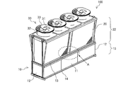
- FIG. 1 is an external perspective view of the chilling unit 100 according to the embodiment.
- the chilling unit 100 according to the present embodiment cools or heats a heat transfer fluid such as water or antifreeze supplied from the user side device, supplies the heat transfer fluid to the user side device, and circulates the heat transfer fluid to the user side device. It is used as a heat source device that supplies cold or hot heat.
- the chilling unit 100 includes a housing 10, an air heat exchanger 20 provided on the upper part of the housing 10, and a first fan unit 30 provided on the upper part of the air heat exchanger 20.
- the housing 10 is mounted on a horizontal installation surface such as the roof of a building. Further, the housing 10 is formed in an elongated hollow box shape in which the depth dimension is much larger than the width dimension.
- a plurality of first side plates 11 are provided on both side surfaces on the longitudinal side of the housing 10.
- Second side plates 12 are provided on both side surfaces on the short side of the housing 10.
- a drain plate 13 is provided on the upper surface of the housing 10.
- a bottom plate 14 is provided on the bottom surface of the housing 10. Further, inside the housing 10, a rectangular machine room 15 in a plan view is formed, which is surrounded by a first side plate 11, a second side plate 12, a drain plate 13, and a bottom plate 14.
- a plurality of, for example, two air heat exchangers 20 are provided along the depth direction on both side surfaces on the longitudinal side of the chilling unit 100. Further, the air heat exchangers 20 are arranged so as to face each other at intervals in the width direction of the housing 10, and are tilted toward each other as they move upward.
- the air heat exchanger 20 is configured by combining a plurality of plate fins and a plurality of refrigerant pipes. Further, a blower chamber 22 extending in the vertical direction is formed between the air heat exchangers 20 facing each other.
- the first fan unit 30 includes a fan 31, a fan motor (not shown) for driving the fan 31, and a cylindrical fan cover 32 that covers the outer periphery of the fan 31. Further, a first exhaust port 33 is formed inside the fan cover 32.
- the air around the chilling unit 100 passes through the air heat exchanger 20 and is sucked into the blower chamber 22.
- the air sucked into the blower chamber 22 is sucked up toward the first exhaust port 33 and discharged from the first exhaust port 33 toward the upper side of the chilling unit 100.
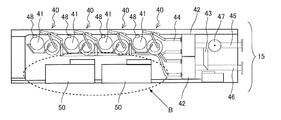
- FIG. 2 is a plan view of a cross section of the housing 10 of the chilling unit 100 according to the embodiment.
- a refrigerant circuit 40 including a compressor 41 and the like, and a box-shaped control box 50 containing various electric components for controlling the refrigerant circuit 40 are provided.
- a plurality of refrigerant circuits 40 are installed along the longitudinal direction on one of the longitudinal side surfaces of the housing 10.
- Each refrigerant circuit 40 has a system independent of each other for each air heat exchanger 20, and a total of four compressors 41 and the like are provided corresponding to each air heat exchanger 20.
- a plurality of control boxes 50 are installed along the longitudinal direction on the side surface side of the other longitudinal side of the housing 10.
- Examples of electrical components housed in the control box 50 include a compressor board that controls the compressor 41, a fan board that controls the first fan unit 30, a plurality of power modules such as an inverter and a converter, and a plurality of smoothing machines. Capacitors and multiple reactors for improving power factor.
- the control box 50 is configured to control two refrigerant circuits 40, respectively, and a total of two control boxes 50 are provided. Further, inside the machine room 15, a plurality of water heat exchangers 42 are installed on one end side of the chilling unit 100 in the longitudinal direction.
- the water heat exchanger 42 heats between a heat transfer fluid such as water / antifreeze, which is supplied from a user-side device installed outside the chilling unit 100, and a refrigerant in a refrigeration cycle constituting the refrigerant circuit 40. It consists of a group of plate heat exchangers for replacement.
- the water heat exchanger 42 is configured by using a plurality of plate heat exchangers in which the flow paths are connected by the first connection pipe 43.
- two plate heat exchangers arranged in parallel are installed so as to be connected in series.
- the primary side of the water heat exchanger 42 is connected to the refrigerant circuit 40 on the heat source side by a second connection pipe 44, and the secondary side returns from the supply pipe 46 that sends the heat transfer fluid to the user side and the user side.
- the return pipe 45 that receives the heat transfer fluid is connected so as to extend to the outside, and is configured to circulate between the heat source side and the utilization side.
- the second connection pipe 44 in the water heat exchanger 42 is independent of each other inside the water heat exchanger 42. There are four sets connected to the flow path formed by the above. Further, when the supply power for circulation of the heat transfer fluid cannot be prepared by the equipment at the place where the heat source unit is installed, the product is provided in the form in which the liquid pump 47 is connected to the attachment portion of the return pipe 45.
- the refrigerant circuit 40 is operated, the fan motor provided on the upper part of the air heat exchanger 20 is operated, and the fan 31 is rotated.
- the outside air passes between a large number of plate fins from the outer side surface of the air heat exchanger 20 and is sucked into the blower chamber 22.
- the air sucked into the blower chamber 22 is sucked up toward the first exhaust port 33 and discharged from the first exhaust port 33 toward the upper side of the chilling unit 100.
- the refrigerant sent from the refrigerant circuit 40 and the outside air around the side surface of the air heat exchanger 20 are heat-exchanged, and the heat-exchanged outside air is discharged above the chilling unit 100.
- the heat-exchanged refrigerant is heat-exchanged with a heat transfer fluid such as water or antifreeze liquid supplied via the return pipe 45 by the water heat exchanger 42 included in the refrigerant circuit 40, and the refrigerant is in the refrigerant circuit 40.
- the heat transfer fluid supplied from the outside is discharged to the outside through the supply pipe 46.
- a liquid pump 47 is inserted in the return pipe 45, and the liquid pump 47 is operated on the heat source side.
- the heat transfer fluid is supplied and circulated from the outside.
- a switching valve 48 is provided in the refrigerant circuit 40, and the refrigerant compressed by the compressor 41 is supplied from the outside by reversing the route through which the air heat exchanger 20 and the water heat exchanger 42 pass.
- the heat transfer fluid can be both cooled and heated.
- FIG. 3 is a plan view of the arrow B view portion of FIG. 2 as viewed from the back side of the control box 50.
- FIG. 4 is a perspective view of the arrow B viewing portion of FIG. 2 as viewed from the rear side of the control box 50.
- FIG. 5 is a perspective view showing the periphery of the gap t between the two control boxes 50 according to the embodiment.
- FIG. 6 is a side view of the control box 50 according to the embodiment. Note that FIG. 5 does not show the configuration of one of the two control boxes 50 on the back side of the control box 50. Further, FIG. 6 shows a control box 50 in a state where the duct 53 is removed.
- the two control boxes 50 are arranged on one side surface with a gap t such that a human fist can be inserted.
- a fan board heat sink 51 for cooling the fan board and a fan board heat sink 51 are arranged under the fan board heat sink 51 to cool the compressor board.
- the compressor board heat sink 52 of the above is provided.
- a duct 53 that covers the fan substrate heat sink 51 and the compressor substrate heat sink 52 to form an air passage is provided on the back side of each control box 50.
- a second fan unit 60 is provided which is arranged directly under the duct 53 and blows air to the duct 53 to exhaust the heated air around the control box 50 which is a heat generation source. ing. Therefore, the duct 53 forms an air passage for exhausting the air heated around the control box 50 so as not to be agitated around the compressor 41 or the like.
- the second fan unit 60 is screw-fixed while being placed on the base sheet metal 54 attached to the bottom plate 14.
- the base sheet metal 54 is provided so as to extend in the width direction of the control box 50. Further, the two base sheet metals 54 are arranged with a gap smaller than the width of the second fan unit 60 between them.
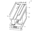
- FIG. 7 is an enlarged perspective view of the vertical cross section of the arrow A viewing portion of FIG.
- FIG. 8 is a perspective view of the periphery of the drain plate 13 of the housing 10 according to the embodiment.
- FIG. 9 is an enlarged view of the periphery of the ventilation hole 13a of the drain plate 13 of the housing 10 according to the embodiment.
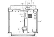
- FIG. 10 is a plan view of a vertical cross section of the housing 10 shown in FIG.
- FIG. 11 is an enlarged view of the arrowhead portion D in FIG. The arrows in FIG. 11 indicate the flow of air.
- the drain plate 13 is formed with a ventilation hole 13a through which air flowing from the duct 53 to the blower chamber 22 passes.
- a plurality of the ventilation holes 13a are formed along the longitudinal direction of the drain plate 13, and these ventilation holes 13a are formed above the duct 53.
- a peripheral wall portion 13b is provided on the peripheral edge of the ventilation hole 13a.
- a downwardly recessed drain gutter 13c is formed along the longitudinal direction at the center of the drain plate 13 in the lateral direction.
- a cover member 16 is provided on the upper surface of the drain plate 13 so as to cover all of the plurality of ventilation holes 13a, and the cover member 16 allows rainwater or water from the defrosting operation to enter the blower chamber 22. It suppresses the intrusion into the ventilation hole 13a. Further, the peripheral wall portion 13b enhances the effect of suppressing water from entering the ventilation hole 13a. Further, as shown in FIGS. 7, 10 and 11, the cover member 16 is provided so as to communicate the ventilation holes 13a and the drain gutter 13c. In this way, by providing the cover member 16 so as to communicate the ventilation holes 13a and the drain gutter 13c, it is possible to form an air passage from the machine room 15 to the blower room 22 while improving the drainage property. .. Further, on the lower surface of the drain plate 13, a guide member 17 is provided near the ventilation hole 13a and guides the air from the duct 53 to the ventilation hole 13a.
- the chilling unit 100 is supposed to be installed both indoors and outdoors, and if it is installed outdoors, rain or snow will enter the blower room 22 from the first exhaust port 33. Further, when the outside air temperature around the chilling unit 100 is as low as about 0 degrees Celsius or less, if the heating operation for heating the heat transfer fluid supplied from the user side is continuously performed, the water vapor contained in the outside air is released. Frost is generated by condensing on the surface of the air heat exchanger 20 and further freezing. Since this frost hinders the passage of outside air in the air heat exchanger 20 and reduces the performance of the chilling unit 100, it is temporarily switched to the cooling operation as a control for maintaining the performance.
- the frost on the surface of the air heat exchanger 20 melts, and the passage of outside air becomes normal. Also in this case, a large amount of water formed by melting the frost drips toward the lower part in the blower chamber 22.
- FIG. 12 is an enlarged view of the C arrow viewing portion of FIG.
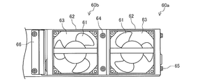
- FIG. 13 is a plan view of the second fan unit 60 according to the embodiment.
- FIG. 14 is an enlarged view of the arrow viewing portion of FIG.
- the two second fan units 60 the one closer to the gap t is referred to as the second fan unit 60a, and the one farther from the gap t is referred to as the second fan unit 60b.
- the second fan units 60a and 60b include the second fan 61, the second fan motor (not shown) for driving the second fan 61, and the outer circumference of the second fan 61. It includes a box-shaped second fan cover 62 and a cover. A second exhaust port 63 is formed inside the second fan cover 62. Further, the height (thickness) of the second fan units 60a and 60b is less than the gap t.
- the two second fan units 60a and 60b are connected in the width direction of the control box 50. In the present embodiment, the two second fan units 60a and 60b are connected, but the present invention is not limited to this, and one second fan unit 60 or three or more second fan units 60 May be concatenated.
- a connecting portion 64 is provided on the upper surface of the second fan unit 60a on the second fan unit 60b side and on the upper surface of the second fan unit 60b on the second fan unit 60a side.
- the second fan unit 60a and the second fan unit 60b are connected by being fixed by a screw which is a detachable fixing means at the connecting portion 64.
- the fixing means of the connecting portion 64 is not limited to screws, and other means such as pins, screws, or bolts may be used.
- the air heated around the control box 50 which is a heat generation source, is sucked up toward the second exhaust port 63, and a duct arranged above the second exhaust port 63. It is blown out toward 53.
- the air blown out to the duct 53 rises in the duct 53 and promotes heat dissipation in the compressor substrate heat sink 52 and the fan substrate heat sink 51 as they pass by the side.
- the air that has passed through the fan substrate heat sink 51 side is discharged from above the duct 53 and then sucked into the ventilation holes 13a formed in the drain plate 13 by the guide member 17.
- the air sucked into the ventilation holes 13a flows between the cover member 16 and the drain plate 13 to the drain gutter 13c, and then is sucked into the blower chamber 22 to exhaust heat.
- the second fan unit 60 is arranged in the lower part on the back side of the control box 50, and air is blown out from the second exhaust port 63 toward the duct 53 arranged above the second exhaust port 63.
- the structure was used. Therefore, the air volume can be increased as compared with the structure in which air is sucked from the duct 53, and the temperature rise of the control box 50 can be suppressed.
- a fixing portion 65 fixed by a screw which is a detachable fixing means, is provided at the lower portion of the side surface of the second fan unit 60a on the side not facing the second fan unit 60b. It is screwed to the upper part of the side surface of the base sheet metal 54 on the gap t side. Further, a protrusion 66 is provided at the lower portion of the side surface of the second fan unit 60b that does not face the second fan unit 60a.
- the fixing means of the fixing portion 65 is not limited to screws, and other means such as pins, screws, or bolts may be used.
- the protrusion 66 is composed of a horizontal portion 66a protruding horizontally from the side surface of the second fan unit 60b and a tip portion 66b inclined upward.
- a stopper 55 is provided at a position on the upper surface of the base sheet metal 54 where the widths of the two second fan units 60a and 60b are separated from the side surface on the gap t side.
- the stopper 55 is provided with a recess 55a into which the tip 66b of the protrusion 66 can be inserted.
- the recess 55a is inclined in the same manner as the tip 66b of the protrusion 66, and is inserted in a state where the tip 66b of the protrusion 66 is tilted horizontally.
- the stopper 55 sandwiches the protrusion 66 and regulates the movement in the longitudinal direction on the base sheet metal 54.
- the two second fan units 60a and 60b are fixed to the base sheet metal 54 by inserting the protrusion 66 into the recess 55a of the stopper 55 and screwing the fixing portion 65 to the side surface of the base sheet metal 54 on the gap t side. Has been done.
- the two second fan units 60a and 60b have their screws removed from the fixing portion 65, and when the second fan unit 60b is tilted and the protrusion 66 is removed from the stopper 55, the two second fan units 54 are placed on the base sheet metal 54 along the longitudinal direction thereof. It can be slid.
- the work space is formed at a position outside the side surface of the chilling unit 100 on the side where the control box 50 is installed.
- FIG. 15 is a first diagram illustrating a method of taking out the second fan unit 60 according to the embodiment.
- FIG. 16 is a second diagram illustrating a method of taking out the second fan unit 60 according to the embodiment.
- FIG. 15 is a view of the longitudinal side surface of the housing 10 viewed from the inside
- FIG. 16 is a view of the longitudinal side surface of the housing 10 viewed from the outside with a work space.
- the broken line in FIG. 15 indicates the position of the second fan unit 60 before the movement
- the arrows in FIGS. 15 and 16 indicate the moving direction of the second fan unit 60.
- a hand holding a screwdriver is put in the gap t formed on one side surface of the control box 50, and in the gap t between the two control boxes 50 in FIG. 15, and the hand is provided on the side surface of the second fan unit 60a.
- the second fan unit 60a is lifted and the connected second fan unit 60b is tilted to pull out the protrusion 66 from the stopper 55.
- the two second fan units 60a and 60b are slid and arranged at positions straddling the two base sheet metals 54.
- the screw is removed from the connecting portion 64 with a screwdriver to release the connection between the second fan unit 60a and the second fan unit 60b. To do. Finally, the two second fan units 60a and 60b are sequentially tilted in the lateral direction and taken out from the gap t.
- the second fan units 60a and 60b arranged at the end do not have the base sheet metal 54 in the sliding direction. In that case, the second fan units 60a and 60b are slid, and when the connecting portion 64 becomes visible from the gap t, the second fan unit 60a and 60b are stopped at that position. Then, with the second fan units 60a and 60b supported by hand, the screw is removed from the connecting portion 64 with a screwdriver to release the connection between the second fan unit 60a and the second fan unit 60b. Finally, the two second fan units 60a and 60b are sequentially tilted in the lateral direction and taken out from the gap t.
- the control box 50 is removed when the second fan unit 60 is taken out from the narrow work space on the longitudinal side surface of the housing 10 of the chilling unit 100. No need to take it out. That is, since the second fan unit 60 can be taken out without taking out the control box 50, the serviceability can be improved as compared with the conventional case.
- the chilling unit 100 is provided with the housing 10 in which the rectangular machine room 15 is formed in a plan view and the upper portion of the housing 10, and the blower room 22 is formed inside. It includes an air heat exchanger 20 and a first fan unit 30 provided above the air heat exchanger 20 and discharging air from the blower chamber 22 to the outside. Further, in the machine room 15 of the housing 10, a plurality of control boxes 50 installed so as to form a gap t on one side surface along the longitudinal direction on one side surface side on the longitudinal side, and each control. A duct 53 provided on the back side of the box 50 and forming an air passage toward the blower chamber 22 and a gap t provided below the duct 53 to blow air around the control box 50 to the duct 53.
- a fixing portion 65 fixed to the base sheet metal 54 by a detachable fixing means is provided on the side surface of the second fan unit 60 on the gap t side, and a protrusion 66 is provided on the other side surface.
- a protrusion 66 is inserted, and a stopper 55 for sandwiching the inserted protrusion 66 is provided.
- the second fan unit 60 is provided so as to be slidable on the base sheet metal 54 in a state where the fixing means is removed from the fixing portion 65 and the protrusion 66 is removed from the stopper 55.
- a fixing portion 65 fixed to the base sheet metal 54 by a detachable fixing means is provided on the side surface of the second fan unit 60 on the gap t side.
- a protrusion 66 is provided on one side surface. Further, on the upper surface of the base sheet metal 54, a protrusion 66 is inserted, and a stopper 55 for sandwiching the inserted protrusion 66 is provided.
- the second fan unit 60 is provided so as to be slidable on the base sheet metal 54 in a state where the fixing means is removed from the fixing portion 65 and the protrusion 66 is removed from the stopper 55. Further, the thickness of the second fan unit 60 is less than the gap t.
- the fixing means is removed from the fixing portion 65, the second fan unit 60 is slid on the base sheet metal 54 with the protrusion 66 removed from the stopper 55, and the second fan unit 60 is moved from the gap t between the control boxes 50. Can be taken out. That is, since the second fan unit 60 can be replaced without removing the control box 50 from the longitudinal side surface of the housing 10 of the chilling unit 100, serviceability can be improved.
- the chilling unit 100 includes two second fan units 60, the other second fan unit 60 side on the upper surface of one second fan unit 60, and the other second fan unit.
- a connecting portion 64 is provided on one side of the upper surface of the 60 on the second fan unit 60 side.
- the two second fan units 60 are connected by being fixed by a detachable fixing means at the connecting portion 64.
- the two second fan units 60 are slid and arranged at a position straddling the two base sheet metals 54.
- the fixing means is removed from the connecting portion 64 with a screwdriver or the like, and the second fan unit 60a and the second fan unit 60b are connected.
- the two second fan units 60 are sequentially tilted in the lateral direction and taken out from the gap t. In this way, even when two second fan units 60 are connected, when the second fan unit 60 is taken out from the narrow work space on the longitudinal side surface of the housing 10 of the chilling unit 100, the control box is used. There is no need to take out 50. That is, since the two connected second fan units 60 can be taken out without taking out the control box 50, the serviceability can be improved as compared with the conventional case.
- the housing 10 has a drain plate 13 which is provided on the upper surface and has a ventilation hole 13a for communicating the machine room 15 and the blower room 22.
- a cover member 16 that covers the ventilation holes 13a is provided on the upper surface of the 13.
- the cover member 16 covering the ventilation holes 13a is provided on the upper surface of the drain plate 13, it is possible to prevent water from entering the ventilation holes 13a. it can.
- the drain plate 13 has a peripheral wall portion 13b protruding upward on the peripheral edge of the ventilation hole 13a. Therefore, the peripheral wall portion 13b can enhance the effect of suppressing water from entering the ventilation holes 13a.
- the drain plate 13 is formed with a downwardly recessed drain gutter 13c, and the cover member 16 communicates the ventilation hole 13a with the drain gutter 13c. ..
- the cover member 16 since the cover member 16 communicates the ventilation holes 13a and the drain gutter 13c, the air passage from the machine room 15 to the blower room 22 while improving the drainage property. Can be formed.
- a guide member 17 for guiding the air discharged from the duct 53 to the ventilation hole 13a is provided on the lower surface of the drain plate 13.
- the guide member 17 for guiding the air discharged from the duct 53 to the ventilation hole 13a is provided on the lower surface of the drain plate 13, the heat exhaustability is improved. be able to.
Landscapes
- Engineering & Computer Science (AREA)
- Mechanical Engineering (AREA)
- General Engineering & Computer Science (AREA)
- Physics & Mathematics (AREA)
- Thermal Sciences (AREA)
- Chemical & Material Sciences (AREA)
- Combustion & Propulsion (AREA)
- Other Air-Conditioning Systems (AREA)
- Cooling Or The Like Of Electrical Apparatus (AREA)
Abstract
チリングユニットは、平面視して長方形状の機械室が形成された筐体と、筐体の上部に設けられ、内部に送風機室が形成された空気熱交換器と、空気熱交換器の上部に設けられ、送風機室の空気を外部に排出する第一ファンユニットと、を備え、筐体の機械室には、一方の長手側の側面側に、長手方向に沿って一方の側面に隙間が形成されるように設置された複数の制御箱と、各制御箱の背面側に設けられ、送風機室に向かう風路を形成するダクトと、ダクトの下側に設けられ、制御箱周辺の空気をダクトに送風する、厚さが隙間未満の第二ファンユニットと、第二ファンユニットを載置する台板金と、を備えており、第二ファンユニットの、隙間側の側面には台板金に着脱可能な固定手段により固定される固定部が設けられており、もう一方の側面には突起部が設けられており、台板金の上面には、突起部が挿入され、挿入された突起部を挟み込むストッパーが設けられており、第二ファンユニットは、固定部から固定手段が外され、ストッパーから突起部が抜かれた状態では、台板金上をスライド可能に設けられているものである。
Description
本発明は、冷温もしくは温水を生成するチリングユニットに関するものである。
従来、機械室に配置され、圧縮機を含む、冷凍サイクル動作を制御する電装ボックスと、電装ボックスの内部の発熱部品から発せられる熱気を排熱可能なファン装置と、を有するチリングユニットがある(例えば、特許文献1参照)。
特許文献1のチリングユニットにおいて、ファン装置は、電装ボックスの上面などに取り付けられており、回転駆動により電装ボックスの内部に空気を発生させる。そして、この空気の流れによって、電装ボックスの内部の熱気が、電装ボックスの上面などに設けられたダクトを通って機外に排熱されることで、電装ボックス内の内部が冷却される。このチリングユニットでは、ファン装置を故障などにより交換しなければならない場合、側面の狭い作業スペースから内部のファン装置を取り出す必要がある。
しかしながら、特許文献1のような従来のチリングユニットでは、ファン装置を交換する際に、側面の狭い作業スペースから電装ボックスを取り出さなければファン装置を取り出すことができないため、サービス性がよくないという課題があった。
本発明は、以上のような課題を解決するためになされたもので、サービス性を向上させたチリングユニットを提供することを目的としている。
本発明に係るチリングユニットは、平面視して長方形状の機械室が形成された筐体と、前記筐体の上部に設けられ、内部に送風機室が形成された空気熱交換器と、前記空気熱交換器の上部に設けられ、前記送風機室の空気を外部に排出する第一ファンユニットと、を備え、前記筐体の前記機械室には、一方の長手側の側面側に、長手方向に沿って一方の側面に隙間が形成されるように設置された複数の制御箱と、各前記制御箱の背面側に設けられ、前記送風機室に向かう風路を形成するダクトと、前記ダクトの下側に設けられ、前記制御箱周辺の空気を前記ダクトに送風する、厚さが前記隙間未満の第二ファンユニットと、前記第二ファンユニットを載置する台板金と、を備えており、前記第二ファンユニットの、前記隙間側の側面には前記台板金に着脱可能な固定手段により固定される固定部が設けられており、もう一方の側面には突起部が設けられており、前記台板金の上面には、前記突起部が挿入され、挿入された前記突起部を挟み込むストッパーが設けられており、前記第二ファンユニットは、前記固定部から前記固定手段が外され、前記ストッパーから前記突起部が抜かれた状態では、前記台板金上をスライド可能に設けられているものである。
本発明に係るチリングユニットによれば、第二ファンユニットの、隙間側の側面には台板金に着脱可能な固定手段により固定される固定部が設けられており、もう一方の側面には突起部が設けられており、台板金の上面には、突起部が挿入され、挿入された突起部を挟み込むストッパーが設けられている。そして、第二ファンユニットは、固定部から固定手段が外され、ストッパーから突起部が抜かれた状態では、台板金上をスライド可能に設けられているものである。さらに、第二ファンユニットの厚さは、隙間未満である。そのため、固定部からネジを外し、ストッパーから突起部を抜いた状態で第二ファンユニットを台板金上でスライドさせ、隙間から第二ファンユニットを取り出すことができる。つまり、チリングユニットの筐体の長手側の側面から制御箱を取り出すことなく第二ファンユニットを交換することができるため、サービス性を向上させることができる。
以下、本発明の実施の形態を図面に基づいて説明する。なお、以下に説明する実施の形態によって本発明が限定されるものではない。また、以下の図面では各構成部材の大きさの関係が実際のものとは異なる場合がある。
また、以下の説明において、理解を容易にするために方向を表す用語(例えば「上」、「下」、「右」、「左」、「前」、「後」など)を適宜用いるが、これは説明のためのものであって、これらの用語は本願発明を限定するものではない。また、以下に説明する実施の形態では、チリングユニット100を正面視した状態において、「上」、「下」、「右」、「左」、「前」、「後」などを使用する。
実施の形態.
図1は、実施の形態に係るチリングユニット100の外観斜視図である。
本実施の形態に係るチリングユニット100は、例えば利用側装置から供給される水・不凍液などの伝熱流体を冷却または加熱して利用側装置に送給し、循環することにより、利用側装置に冷熱または温熱を供給する熱源装置として利用されるものである。
図1は、実施の形態に係るチリングユニット100の外観斜視図である。
本実施の形態に係るチリングユニット100は、例えば利用側装置から供給される水・不凍液などの伝熱流体を冷却または加熱して利用側装置に送給し、循環することにより、利用側装置に冷熱または温熱を供給する熱源装置として利用されるものである。
チリングユニット100は、筐体10と、筐体10の上部に設けられた空気熱交換器20と、空気熱交換器20の上部に設けられた第一ファンユニット30とを備えている。筐体10は、例えば建物の屋上のような水平な設置面に上に据え付けられている。また、筐体10は、奥行き寸法が幅寸法よりも格段に大きな細長い中空の箱状に形成されている。筐体10の長手側の両側面には、それぞれ複数の第一側板11が設けられている。筐体10の短手側の両側面には、それぞれ第二側板12が設けられている。筐体10の上面には、ドレン板13が設けられている。筐体10の底面には、底板14が設けられている。また、筐体10の内部には、第一側板11、第二側板12、ドレン板13、および、底板14で囲まれた、平面視して長方形状の機械室15が形成されている。
空気熱交換器20は、チリングユニット100の長手側の両側面に、奥行き方向に沿って複数、例えば2つ設けられている。また、空気熱交換器20は、筐体10の幅方向に間隔を空けて向かい合うように配置されており、上方に進むに従い互いに遠ざかる方向に傾けられている。空気熱交換器20は、複数のプレートフィンと複数の冷媒配管とを組み合わせて構成されている。また、向かい合う空気熱交換器20の間には、上下方向に延びた送風機室22が形成されている。
第一ファンユニット30は、奥行き方向に沿って複数、例えば4つ設けられている。第一ファンユニット30は、ファン31と、ファン31を駆動するファンモータ(図示せず)と、ファン31の外周を覆う円筒形状のファンカバー32と、を備えている。また、ファンカバー32の内部には、第一排気口33が形成されている。
ファン31が駆動されると、チリングユニット100の周囲の空気が空気熱交換器20を通過して送風機室22に吸い込まれる。送風機室22に吸い込まれた空気は、第一排気口33に向けて吸い上げられるとともに、第一排気口33からチリングユニット100の上方に向けて排出される。
図2は、実施の形態に係るチリングユニット100の筐体10の横断面を平面視した図である。
機械室15の内部には、圧縮機41などを含む冷媒回路40と、冷媒回路40を制御する各種の電気部品を収容した箱体形状の制御箱50とが設けられている。冷媒回路40は、筐体10の一方の長手側の側面側に、長手方向に沿って複数設置されている。各冷媒回路40は、各空気熱交換器20に対して互いに独立した系統となっており、圧縮機41なども各空気熱交換器20に対応して合計4台設けられている。制御箱50は、筐体10の他の長手側の側面側に、長手方向に沿って複数設置されている。制御箱50に収容されている電気部品の一例としては、圧縮機41を制御する圧縮機基板、第一ファンユニット30を制御するファン基板、インバータおよびコンバータのような複数のパワーモジュール、複数の平滑コンデンサ、および、力率改善用の複数のリアクトルなどである。制御箱50は、それぞれ2つの冷媒回路40を制御するように構成されており、合計2台設けられている。また、機械室15の内部には、チリングユニット100の長手方向の一端部側に水熱交換器42が複数設置されている。水熱交換器42は、チリングユニット100の外部に設置された利用側装置から供給される例えば、水・不凍液などの伝熱流体と、冷媒回路40を構成する冷凍サイクルの冷媒との間で熱交換するためのプレート熱交換器群からなっている。
機械室15の内部には、圧縮機41などを含む冷媒回路40と、冷媒回路40を制御する各種の電気部品を収容した箱体形状の制御箱50とが設けられている。冷媒回路40は、筐体10の一方の長手側の側面側に、長手方向に沿って複数設置されている。各冷媒回路40は、各空気熱交換器20に対して互いに独立した系統となっており、圧縮機41なども各空気熱交換器20に対応して合計4台設けられている。制御箱50は、筐体10の他の長手側の側面側に、長手方向に沿って複数設置されている。制御箱50に収容されている電気部品の一例としては、圧縮機41を制御する圧縮機基板、第一ファンユニット30を制御するファン基板、インバータおよびコンバータのような複数のパワーモジュール、複数の平滑コンデンサ、および、力率改善用の複数のリアクトルなどである。制御箱50は、それぞれ2つの冷媒回路40を制御するように構成されており、合計2台設けられている。また、機械室15の内部には、チリングユニット100の長手方向の一端部側に水熱交換器42が複数設置されている。水熱交換器42は、チリングユニット100の外部に設置された利用側装置から供給される例えば、水・不凍液などの伝熱流体と、冷媒回路40を構成する冷凍サイクルの冷媒との間で熱交換するためのプレート熱交換器群からなっている。
水熱交換器42は、第一接続配管43で流路を連結された複数のプレート熱交換器を用いて構成されている。この例では、2つのプレート熱交換器を並列化したものを直列に接続するように設置されている。その水熱交換器42の1次側は熱源側の冷媒回路40に対して第二接続配管44によって接続され、2次側は利用側に伝熱流体を送る送給管46と利用側から戻る伝熱流体を受け入れる戻り管45が外部に延びる形で接続され、熱源側と利用側で循環されるように構成されている。なお、この例では互いに独立した4系統の冷凍サイクルを有する冷媒回路40が設置されているので、水熱交換器42における第二接続配管44は、その水熱交換器42の内部に互いに独立して形成された流路に繋がる4組が設けられている。また、伝熱流体の循環用の供給動力が熱源ユニット設置場所の設備で準備ができない場合は、戻り管45の取り付け部に液体ポンプ47が連結された形態での製品提供がなされる。
ここで、上記のように構成されたチリングユニット100の動作について説明する。冷媒回路40を動作させ、空気熱交換器20の上部に設けられたファンモータを作動させ、ファン31を回転させる。そうすることにより、外気が空気熱交換器20の外側の側面から多数のプレートフィンの間を通過して送風機室22に吸い込まれる。送風機室22に吸い込まれた空気は、第一排気口33に向けて吸い上げられるとともに、第一排気口33からチリングユニット100の上方に向けて排出される。この動作により、冷媒回路40から送られてきた冷媒と空気熱交換器20の側面の周囲の外気とが熱交換され、熱交換された外気はチリングユニット100の上方へと排出される。
なお、熱交換された冷媒は、冷媒回路40内に含まれる水熱交換器42で戻り管45を介して供給される水・不凍液などの伝熱流体と熱交換され、冷媒は冷媒回路40内に再び戻り、外部から供給された伝熱流体は送給管46を介して外部へと排出される。なお、伝熱流体の外部からの供給にあたり、伝熱流体供給の動力源を利用側で準備できない場合、戻り管45に液体ポンプ47が介挿され、熱源側でその液体ポンプ47を稼働させることにより伝熱流体の外部からの供給・循環を行う。なお、冷媒回路40内に切替弁48を設け、圧縮機41で圧縮された冷媒を空気熱交換器20と水熱交換器42とに通流させる順路を逆にすることで、外部から供給される伝熱流体は冷却および加熱の両方を行うことができる。
図3は、図2のB矢視部を制御箱50の背面側から見た平面図である。図4は、図2のB矢視部を制御箱50の背面側から見た斜視図である。図5は、実施の形態に係る2つの制御箱50の間の隙間t周辺を示す斜視図である。図6は、実施の形態に係る制御箱50を側面視した図である。なお、図5は、2つの制御箱50のうち一方の制御箱50の背面側の構成を図示省略している。また、図6は、ダクト53が取り外された状態の制御箱50を示している。
図3~図5に示すように、2つの制御箱50は、一方の側面に人の握り拳が入る程度の隙間tが空けられて配置されている。また、図6に示すように、各制御箱50の背面側には、ファン基板を冷却するためのファン基板ヒートシンク51と、ファン基板ヒートシンク51の下側に配置され、圧縮機基板を冷却するための圧縮機基板ヒートシンク52と、が設けられている。さらに、図3~図5に示すように、各制御箱50の背面側には、ファン基板ヒートシンク51および圧縮機基板ヒートシンク52を覆って風路を形成するダクト53が設けられている。
また、各制御箱50の背面側には、ダクト53の直下に配置され、ダクト53に送風して発熱源となる制御箱50周辺で熱せられた空気を排気する第二ファンユニット60が設けられている。そのため、ダクト53は、制御箱50周辺で熱せられた空気を圧縮機41など周囲に撹拌されないように排気するための風路を形成している。第二ファンユニット60は、底板14に取り付けられている台板金54の上に載置された状態でネジ固定されている。台板金54は、制御箱50の幅方向に延びるように設けられている。また、2つの台板金54は、それらの間に第二ファンユニット60の幅よりも小さい隙間を空けて配置されている。
図7は、図1のA矢視部の縦断面を拡大した斜視図である。図8は、実施の形態に係る筐体10のドレン板13周辺の斜視図である。図9は、実施の形態に係る筐体10のドレン板13の通気孔13a周辺の拡大図である。図10は、図8に示す筐体10の縦断面の平面図である。図11は、図10のD矢視部を拡大した図である。なお、図11中の矢印は、空気の流れを示している。
図7、図9、および、図10に示すように、ドレン板13には、ダクト53から送風機室22へ流れる空気が通過する通気孔13aが形成されている。この通気孔13aは、ドレン板13の長手方向に沿って複数形成されており、それら通気孔13aは、ダクト53の上方に形成されている。また、通気孔13aの周縁には、周壁部13bが設けられている。また、図7および図8に示すように、ドレン板13の短手方向中心には、下方に凹んだドレン樋13cが長手方向に沿って形成されている。また、ドレン板13の上面には、複数の通気孔13aを全て覆うようにカバー部材16が設けられており、このカバー部材16によって、送風機室22内に入り込んだ雨水あるいは除霜運転による水が通気孔13aに浸入するのを抑制している。さらに、周壁部13bによって、水が通気孔13aに浸入するのを抑制する効果を高めている。また、図7、図10、および、図11に示すように、カバー部材16は、各通気孔13aとドレン樋13cとを連通させるように設けられている。このように、各通気孔13aとドレン樋13cとを連通させるようにカバー部材16を設けることで、排水性を向上させつつ、機械室15から送風機室22へ向かう風路を形成することができる。また、ドレン板13の下面には、通気孔13aの近くに設けられ、ダクト53からの空気を通気孔13aに案内するガイド部材17が設けられている。
チリングユニット100は、室内および屋外両方への設置が想定されており、屋外へ設置した場合、雨あるいは雪などが第一排気口33から送風機室22内に入り込むこととなる。また、チリングユニット100の周囲の外気温度が摂氏0度程度以下の低温である場合、利用側から供給された伝熱流体を加熱する暖房運転を継続して行うと、外気中に含まれる水蒸気が空気熱交換器20の表面で凝縮し、さらに凍ることで霜が生成される。この霜は空気熱交換器20での外気の通過を妨げ、チリングユニット100の性能を低減させてしまうので、性能維持のための制御として、一時的に冷房運転に切り替えられる。冷房運転を行うことで空気熱交換器20の表面温度が上昇するため、空気熱交換器20の表面に付いた霜が溶け、外気の通過が通常通りになる。この場合も、霜が融けてできた大量の水が送風機室22内の下部方向に滴下する。
このようにして送風機室22内に入り込んだ雨水あるいは除霜運転による水は、ドレン板13またはカバー部材16へと落下する。その落下した水は、ドレン板13およびカバー部材16に沿って短手方向中心側に流れていき、ドレン樋13cへと落下する。ドレン樋13cはチリングユニット100の長手方向に傾いており、ドレン樋13cの下流側に取り付けられたドレン排出口(図示せず)から水が排出される。
図12は、図4のC矢視部を拡大した図である。図13は、実施の形態に係る第二ファンユニット60を平面視した図である。図14は、図12のE矢視部を拡大した図である。なお、以下において、2つの第二ファンユニット60のうち、隙間tに近い方を第二ファンユニット60a、遠い方を第二ファンユニット60bとする。
図12および図13に示すように、第二ファンユニット60a、60bは、第二ファン61と、第二ファン61を駆動する第二ファンモータ(図示せず)と、第二ファン61の外周を覆う箱形状の第二ファンカバー62と、を備えている。また、第二ファンカバー62の内部には、第二排気口63が形成されている。また、第二ファンユニット60a、60bは、高さ(厚さ)が隙間t未満となっている。本実施の形態では、2つの第二ファンユニット60a、60bが、制御箱50の幅方向に連結されている。なお、本実施の形態では、2つの第二ファンユニット60a、60bが連結された構成であるが、それに限定されず、1つの第二ファンユニット60、または、3つ以上の第二ファンユニット60が連結された構成でもよい。
第二ファンユニット60aの上面の第二ファンユニット60b側、および、第二ファンユニット60bの上面の第二ファンユニット60a側には、連結部64が設けられている。そして、第二ファンユニット60aと第二ファンユニット60bとは、連結部64で着脱可能な固定手段であるネジによって固定されることで連結されている。なお、連結部64の固定手段としては、ネジに限定されず、例えばピン、ビス、あるいはボルトなど別の手段でもよい。
第二ファン61が駆動されると、発熱源となる制御箱50周辺で熱せられた空気が第二排気口63に向けて吸い上げられるとともに、第二排気口63からその上方に配置されているダクト53に向けて吹き出される。ダクト53に吹き出された空気は、ダクト53内を上昇し、圧縮機基板ヒートシンク52およびファン基板ヒートシンク51の側を通過する際にそれらにおける放熱を促す。その後、ファン基板ヒートシンク51の側を通過した空気は、図11に示すように、ダクト53の上方から排出された後、ガイド部材17によってドレン板13に形成された通気孔13aに吸い込まれる。通気孔13aに吸い込まれた空気は、カバー部材16とドレン板13との間を通ってドレン樋13cに流れ、その後、送風機室22に吸い込まれ、排熱される。このように、本実施の形態では、第二ファンユニット60を、制御箱50の背面側の下部に配置し、第二排気口63からその上方に配置されているダクト53に向けて空気を吹き出す構造とした。そのため、ダクト53から空気を吸い込む構造に比べて風量を大きく取ることができ、制御箱50の温度上昇を抑制することができる。
図12および図13に示すように、第二ファンユニット60aの、第二ファンユニット60bと対向しない方の側面の下部には、着脱可能な固定手段であるネジによって固定される固定部65が設けられており、台板金54の隙間t側の側面の上部にネジ固定されている。また、第二ファンユニット60bの、第二ファンユニット60aと対向しない方の側面の下部には、突起部66が設けられている。なお、固定部65の固定手段としては、ネジに限定されず、例えばピン、ビス、あるいはボルトなど別の手段でもよい。
図14に示すように、突起部66は、第二ファンユニット60bの側面から水平方向に突出した水平部66aと、上方に傾斜がつけられた先端部66bとで構成されている。また、台板金54の上面の、隙間t側の側面から2つの第二ファンユニット60a、60bの幅分離れた位置には、ストッパー55が設けられている。ストッパー55には、突起部66の先端部66bが挿入可能な凹部55aが設けられている。この凹部55aには、突起部66の先端部66bと同様の傾斜がつけられており、突起部66の先端部66bが水平となるように傾けられた状態で挿入される。そうなることで、ストッパー55が突起部66を挟み込み、台板金54上の長手方向の動きを規制する。
2つの第二ファンユニット60a、60bは、ストッパー55の凹部55aに突起部66が挿入され、固定部65が台板金54の隙間t側の側面にネジ固定されることにより、台板金54に固定されている。2つの第二ファンユニット60a、60bは、固定部65からネジを外し、第二ファンユニット60bを傾けてストッパー55から突起部66を抜いた状態では、台板金54上をその長手方向に沿ってスライドできるようになっている。
第二ファンユニット60を故障などにより交換しなければならない場合、チリングユニット100の筐体10の長手側の側面の外側の狭い作業スペースから内部の第二ファンユニット60を取り出す必要がある。次に、第二ファンユニット60の取り出し方法について説明する。なお、作業スペースは、チリングユニット100の制御箱50が設置されている側の側面の外側の位置に形成される。
図15は、実施の形態に係る第二ファンユニット60の取り出し方法を説明する第一の図である。図16は、実施の形態に係る第二ファンユニット60の取り出し方法を説明する第二の図である。なお、図15は、筐体10の長手側の側面を内側から見た図であり、図16は、筐体10の長手側の側面を作業スペースがある外側から見た図である。また、図15中の破線は、移動前の第二ファンユニット60の位置を示しており、図15および図16中の矢印は、第二ファンユニット60の移動方向を示している。
まず始めに、制御箱50の一方の側面に形成された隙間t、図15では2つの制御箱50の間の隙間tにドライバーを持った手を入れ、第二ファンユニット60aの側面に設けられている固定部65からネジをドライバーで外す。次に、第二ファンユニット60aを持ち上げて連結された第二ファンユニット60bを傾けてストッパー55から突起部66を抜く。次に、2つの第二ファンユニット60a、60bをスライドさせ、2つの台板金54に跨がる位置に配置する。このとき、連結部64が2つの制御箱50の間の隙間tから見える位置に来るので、連結部64からネジをドライバーで外し、第二ファンユニット60aと第二ファンユニット60bとの連結を解除する。最後に、2つの第二ファンユニット60a、60bを、それぞれ順番に短手方向に傾けて隙間tから取り出す。
なお、一番端に配置されている第二ファンユニット60a、60bは、スライド方向に台板金54がない。その場合は、第二ファンユニット60a、60bをスライドさせて連結部64が隙間tから見える位置になったらその位置で停止する。そして、第二ファンユニット60a、60bを手で支えた状態で連結部64からネジをドライバーで外し、第二ファンユニット60aと第二ファンユニット60bとの連結を解除する。最後に、2つの第二ファンユニット60a、60bを、それぞれ順番に短手方向に傾けて隙間tから取り出す。
このように、本実施の形態では、第二ファンユニット60の交換時、チリングユニット100の筐体10の長手側の側面の狭い作業スペースから第二ファンユニット60を取り出す際に、制御箱50を取り出す必要がない。つまり、制御箱50を取り出すことなく第二ファンユニット60を取り出すことができるため、従来に比べてサービス性を向上させることができる。
以上、本実施の形態に係るチリングユニット100は、平面視して長方形状の機械室15が形成された筐体10と、筐体10の上部に設けられ、内部に送風機室22が形成された空気熱交換器20と、空気熱交換器20の上部に設けられ、送風機室22の空気を外部に排出する第一ファンユニット30と、を備えている。また、筐体10の機械室15には、一方の長手側の側面側に、長手方向に沿って一方の側面に隙間tが形成されるように設置された複数の制御箱50と、各制御箱50の背面側に設けられ、送風機室22に向かう風路を形成するダクト53と、ダクト53の下側に設けられ、制御箱50周辺の空気をダクト53に送風する、厚さが隙間t未満の第二ファンユニット60と、第二ファンユニット60を載置する台板金54と、を備えている。また、第二ファンユニット60の、隙間t側の側面には台板金54に着脱可能な固定手段により固定される固定部65が設けられており、もう一方の側面には突起部66が設けられている。また、台板金54の上面には、突起部66が挿入され、挿入された突起部66を挟み込むストッパー55が設けられている。そして、第二ファンユニット60は、固定部65から固定手段が外され、ストッパー55から突起部66が抜かれた状態では、台板金54上をスライド可能に設けられているものである。
本実施の形態に係るチリングユニット100によれば、第二ファンユニット60の、隙間t側の側面には台板金54に着脱可能な固定手段により固定される固定部65が設けられており、もう一方の側面には突起部66が設けられている。また、台板金54の上面には、突起部66が挿入され、挿入された突起部66を挟み込むストッパー55が設けられている。そして、第二ファンユニット60は、固定部65から固定手段が外され、ストッパー55から突起部66が抜かれた状態では、台板金54上をスライド可能に設けられているものである。さらに、第二ファンユニット60の厚さは、隙間t未満である。そのため、固定部65から固定手段を外し、ストッパー55から突起部66を抜いた状態で第二ファンユニット60を台板金54上でスライドさせ、制御箱50間の隙間tから第二ファンユニット60を取り出すことができる。つまり、チリングユニット100の筐体10の長手側の側面から、制御箱50を取り出すことなく第二ファンユニット60を交換することができるため、サービス性を向上させることができる。
また、本実施の形態に係るチリングユニット100は、第二ファンユニット60を2つ備え、一方の第二ファンユニット60の上面の他方の第二ファンユニット60側、および、他方の第二ファンユニット60の上面の一方の第二ファンユニット60側には、連結部64が設けられている。そして、2つの第二ファンユニット60は、連結部64で着脱可能な固定手段により固定されることで連結されている。
本実施の形態に係るチリングユニット100によれば、2つの第二ファンユニット60をスライドさせ、2つの台板金54に跨がる位置に配置する。このとき、連結部64が2つの制御箱50の間の隙間tから見える位置に来るので、連結部64から固定手段をドライバーなどで外し、第二ファンユニット60aと第二ファンユニット60bとの連結を解除する。最後に、2つの第二ファンユニット60を、それぞれ順番に短手方向に傾けて隙間tから取り出す。このように、第二ファンユニット60が2つ連結された場合であっても、チリングユニット100の筐体10の長手側の側面の狭い作業スペースから第二ファンユニット60を取り出す際に、制御箱50を取り出す必要がない。つまり、制御箱50を取り出すことなく連結された2つの第二ファンユニット60を取り出すことができるため、従来に比べてサービス性を向上させることができる。
また、本実施の形態に係るチリングユニット100において、筐体10は、上面に設けられ、機械室15と送風機室22とを連通させる通気孔13aが形成されたドレン板13を有し、ドレン板13の上面には、通気孔13aを覆うカバー部材16が設けられている。
本実施の形態に係るチリングユニット100によれば、ドレン板13の上面には、通気孔13aを覆うカバー部材16が設けられているため、通気孔13aに水が浸入するのを抑制することができる。
また、本実施の形態に係るチリングユニット100において、ドレン板13は、通気孔13aの周縁に、上方に突出した周壁部13bを有している。そのため、周壁部13bによって、水が通気孔13aに浸入するのを抑制する効果を高めることができる。
また、本実施の形態に係るチリングユニット100において、ドレン板13には、下方に凹んだドレン樋13cが形成されており、カバー部材16は、通気孔13aとドレン樋13cとを連通させている。
本実施の形態に係るチリングユニット100によれば、カバー部材16が通気孔13aとドレン樋13cとを連通させているため、排水性を向上させつつ、機械室15から送風機室22へ向かう風路を形成することができる。
また、本実施の形態に係るチリングユニット100において、ドレン板13の下面には、ダクト53から排出された空気を通気孔13aに案内するガイド部材17が設けられている。
本実施の形態に係るチリングユニット100によれば、ドレン板13の下面には、ダクト53から排出された空気を通気孔13aに案内するガイド部材17が設けられているため、排熱性を向上させることができる。
10 筐体、11 第一側板、12 第二側板、13 ドレン板、13a 通気孔、13b 周壁部、13c ドレン樋、14 底板、15 機械室、16 カバー部材、17 ガイド部材、20 空気熱交換器、22 送風機室、30 第一ファンユニット、31 ファン、32 ファンカバー、33 第一排気口、40 冷媒回路、41 圧縮機、42 水熱交換器、43 第一接続配管、44 第二接続配管、45 戻り管、46 送給管、50 制御箱、51 ファン基板ヒートシンク、52 圧縮機基板ヒートシンク、53 ダクト、54 台板金、55 ストッパー、55a 凹部、60 第二ファンユニット、60a 第二ファンユニット、60b 第二ファンユニット、61 第二ファン、62 第二ファンカバー、63 第二排気口、64 連結部、65 固定部、66 突起部、66a 水平部、66b 先端部、100 チリングユニット、t 隙間。
Claims (6)
- 平面視して長方形状の機械室が形成された筐体と、
前記筐体の上部に設けられ、内部に送風機室が形成された空気熱交換器と、
前記空気熱交換器の上部に設けられ、前記送風機室の空気を外部に排出する第一ファンユニットと、を備え、
前記筐体の前記機械室には、
一方の長手側の側面側に、長手方向に沿って一方の側面に隙間が形成されるように設置された複数の制御箱と、
各前記制御箱の背面側に設けられ、前記送風機室に向かう風路を形成するダクトと、
前記ダクトの下側に設けられ、前記制御箱周辺の空気を前記ダクトに送風する、厚さが前記隙間未満の第二ファンユニットと、
前記第二ファンユニットを載置する台板金と、を備えており、
前記第二ファンユニットの、前記隙間側の側面には前記台板金に着脱可能な固定手段により固定される固定部が設けられており、もう一方の側面には突起部が設けられており、
前記台板金の上面には、前記突起部が挿入され、挿入された前記突起部を挟み込むストッパーが設けられており、
前記第二ファンユニットは、
前記固定部から前記固定手段が外され、前記ストッパーから前記突起部が抜かれた状態では、前記台板金上をスライド可能に設けられている
チリングユニット。 - 前記第二ファンユニットを2つ備え、
一方の前記第二ファンユニットの上面の他方の前記第二ファンユニット側、および、他方の前記第二ファンユニットの上面の一方の前記第二ファンユニット側には、連結部が設けられており、
2つの前記第二ファンユニットは、前記連結部で着脱可能な固定手段により固定されることで連結されている
請求項1に記載のチリングユニット。 - 前記筐体は、上面に設けられ、前記機械室と前記送風機室とを連通させる通気孔が形成されたドレン板を有し、
前記ドレン板の上面には、前記通気孔を覆うカバー部材が設けられている
請求項1または2に記載のチリングユニット。 - 前記ドレン板は、前記通気孔の周縁に、上方に突出した周壁部を有している
請求項3に記載のチリングユニット。 - 前記ドレン板には、下方に凹んだドレン樋が形成されており、
前記カバー部材は、前記通気孔と前記ドレン樋とを連通させている
請求項3または4に記載のチリングユニット。 - 前記ドレン板の下面には、前記ダクトから排出された空気を前記通気孔に案内するガイド部材が設けられている
請求項3~5のいずれか一項に記載のチリングユニット。
Priority Applications (2)
| Application Number | Priority Date | Filing Date | Title |
|---|---|---|---|
| PCT/JP2019/031086 WO2021024409A1 (ja) | 2019-08-07 | 2019-08-07 | チリングユニット |
| JP2021538613A JP7113978B2 (ja) | 2019-08-07 | 2019-08-07 | チリングユニット |
Applications Claiming Priority (1)
| Application Number | Priority Date | Filing Date | Title |
|---|---|---|---|
| PCT/JP2019/031086 WO2021024409A1 (ja) | 2019-08-07 | 2019-08-07 | チリングユニット |
Publications (1)
| Publication Number | Publication Date |
|---|---|
| WO2021024409A1 true WO2021024409A1 (ja) | 2021-02-11 |
Family
ID=74503997
Family Applications (1)
| Application Number | Title | Priority Date | Filing Date |
|---|---|---|---|
| PCT/JP2019/031086 Ceased WO2021024409A1 (ja) | 2019-08-07 | 2019-08-07 | チリングユニット |
Country Status (2)
| Country | Link |
|---|---|
| JP (1) | JP7113978B2 (ja) |
| WO (1) | WO2021024409A1 (ja) |
Cited By (3)
| Publication number | Priority date | Publication date | Assignee | Title |
|---|---|---|---|---|
| CN116067040A (zh) * | 2023-01-17 | 2023-05-05 | 广东美的暖通设备有限公司 | 一种空气源热泵机组 |
| WO2025126310A1 (ja) * | 2023-12-12 | 2025-06-19 | 三菱電機株式会社 | チリングユニット |
| WO2025164092A1 (ja) * | 2024-01-29 | 2025-08-07 | 日本キヤリア株式会社 | 熱源機 |
Families Citing this family (1)
| Publication number | Priority date | Publication date | Assignee | Title |
|---|---|---|---|---|
| WO2007058123A1 (ja) * | 2005-11-17 | 2007-05-24 | Shima Seiki Manufacturing, Ltd. | ニットデザイン装置とニットデザイン方法及びそのプログラム |
Citations (2)
| Publication number | Priority date | Publication date | Assignee | Title |
|---|---|---|---|---|
| JPH0989310A (ja) * | 1995-09-26 | 1997-04-04 | Mitsubishi Heavy Ind Ltd | エンジン駆動式空気調和機の室外ユニット |
| WO2017216987A1 (ja) * | 2016-06-16 | 2017-12-21 | 東芝キヤリア株式会社 | 冷凍サイクル装置 |
-
2019
- 2019-08-07 WO PCT/JP2019/031086 patent/WO2021024409A1/ja not_active Ceased
- 2019-08-07 JP JP2021538613A patent/JP7113978B2/ja not_active Expired - Fee Related
Patent Citations (2)
| Publication number | Priority date | Publication date | Assignee | Title |
|---|---|---|---|---|
| JPH0989310A (ja) * | 1995-09-26 | 1997-04-04 | Mitsubishi Heavy Ind Ltd | エンジン駆動式空気調和機の室外ユニット |
| WO2017216987A1 (ja) * | 2016-06-16 | 2017-12-21 | 東芝キヤリア株式会社 | 冷凍サイクル装置 |
Cited By (4)
| Publication number | Priority date | Publication date | Assignee | Title |
|---|---|---|---|---|
| CN116067040A (zh) * | 2023-01-17 | 2023-05-05 | 广东美的暖通设备有限公司 | 一种空气源热泵机组 |
| CN116067040B (zh) * | 2023-01-17 | 2025-07-25 | 广东美的暖通设备有限公司 | 一种空气源热泵机组 |
| WO2025126310A1 (ja) * | 2023-12-12 | 2025-06-19 | 三菱電機株式会社 | チリングユニット |
| WO2025164092A1 (ja) * | 2024-01-29 | 2025-08-07 | 日本キヤリア株式会社 | 熱源機 |
Also Published As
| Publication number | Publication date |
|---|---|
| JP7113978B2 (ja) | 2022-08-05 |
| JPWO2021024409A1 (ja) | 2021-12-09 |
Similar Documents
| Publication | Publication Date | Title |
|---|---|---|
| US8413461B2 (en) | Auxiliary cooling system | |
| JP5126343B2 (ja) | 空気調和装置 | |
| WO2021024409A1 (ja) | チリングユニット | |
| JP5310887B2 (ja) | 室外機及び冷凍装置 | |
| US20090081940A1 (en) | Outdoor unit of air conditioner | |
| JP5296457B2 (ja) | 空調システム | |
| JP2008182233A (ja) | 熱交換器を備えた、差込式の電子部品を受け入れるためのスイッチキャビネット | |
| JP5505055B2 (ja) | 冷凍装置 | |
| JP2010175224A (ja) | 空気調和装置 | |
| JP2009030885A (ja) | 室外ユニット | |
| US20180010836A1 (en) | Heat transfer unit | |
| US9353968B2 (en) | Heat source unit of refrigerating apparatus | |
| JP2012087954A (ja) | 熱源装置 | |
| CN110785613B (zh) | 制冷机室外单元 | |
| WO2017078144A1 (ja) | 室外機及びそれを用いた空気調和装置 | |
| JP2010181095A (ja) | 空気調和機の室外機 | |
| US12038183B2 (en) | Chilling unit and chilling unit system | |
| KR102168620B1 (ko) | 공기조화기의 실외기 | |
| KR20150000404A (ko) | 열원장치 | |
| JP2014178113A (ja) | 熱源装置 | |
| JP5640791B2 (ja) | 冷凍装置の室外ユニット | |
| JPWO2021024406A1 (ja) | チリングユニット及びチリングユニットシステム | |
| JP2016200333A (ja) | 冷凍サイクル装置 | |
| JP2013135177A (ja) | 電装箱の冷却構造 | |
| KR20110045409A (ko) | 잠열식 열전소자 냉각장치 |
Legal Events
| Date | Code | Title | Description |
|---|---|---|---|
| 121 | Ep: the epo has been informed by wipo that ep was designated in this application |
Ref document number: 19940852 Country of ref document: EP Kind code of ref document: A1 |
|
| ENP | Entry into the national phase |
Ref document number: 2021538613 Country of ref document: JP Kind code of ref document: A |
|
| NENP | Non-entry into the national phase |
Ref country code: DE |
|
| 122 | Ep: pct application non-entry in european phase |
Ref document number: 19940852 Country of ref document: EP Kind code of ref document: A1 |