WO2021019974A1 - Pile à combustible et procédé de fabrication de pile à combustible - Google Patents
Pile à combustible et procédé de fabrication de pile à combustible Download PDFInfo
- Publication number
- WO2021019974A1 WO2021019974A1 PCT/JP2020/024777 JP2020024777W WO2021019974A1 WO 2021019974 A1 WO2021019974 A1 WO 2021019974A1 JP 2020024777 W JP2020024777 W JP 2020024777W WO 2021019974 A1 WO2021019974 A1 WO 2021019974A1
- Authority
- WO
- WIPO (PCT)
- Prior art keywords
- side separator
- electrode composite
- separator
- fuel cell
- membrane electrode
- Prior art date
Links
Images


Classifications
-
- F—MECHANICAL ENGINEERING; LIGHTING; HEATING; WEAPONS; BLASTING
- F16—ENGINEERING ELEMENTS AND UNITS; GENERAL MEASURES FOR PRODUCING AND MAINTAINING EFFECTIVE FUNCTIONING OF MACHINES OR INSTALLATIONS; THERMAL INSULATION IN GENERAL
- F16J—PISTONS; CYLINDERS; SEALINGS
- F16J15/00—Sealings
- F16J15/02—Sealings between relatively-stationary surfaces
- F16J15/06—Sealings between relatively-stationary surfaces with solid packing compressed between sealing surfaces
- F16J15/10—Sealings between relatively-stationary surfaces with solid packing compressed between sealing surfaces with non-metallic packing
- F16J15/12—Sealings between relatively-stationary surfaces with solid packing compressed between sealing surfaces with non-metallic packing with metal reinforcement or covering
-
- H—ELECTRICITY
- H01—ELECTRIC ELEMENTS
- H01M—PROCESSES OR MEANS, e.g. BATTERIES, FOR THE DIRECT CONVERSION OF CHEMICAL ENERGY INTO ELECTRICAL ENERGY
- H01M8/00—Fuel cells; Manufacture thereof
- H01M8/02—Details
-
- H—ELECTRICITY
- H01—ELECTRIC ELEMENTS
- H01M—PROCESSES OR MEANS, e.g. BATTERIES, FOR THE DIRECT CONVERSION OF CHEMICAL ENERGY INTO ELECTRICAL ENERGY
- H01M8/00—Fuel cells; Manufacture thereof
- H01M8/02—Details
- H01M8/0202—Collectors; Separators, e.g. bipolar separators; Interconnectors
- H01M8/0258—Collectors; Separators, e.g. bipolar separators; Interconnectors characterised by the configuration of channels, e.g. by the flow field of the reactant or coolant
-
- H—ELECTRICITY
- H01—ELECTRIC ELEMENTS
- H01M—PROCESSES OR MEANS, e.g. BATTERIES, FOR THE DIRECT CONVERSION OF CHEMICAL ENERGY INTO ELECTRICAL ENERGY
- H01M8/00—Fuel cells; Manufacture thereof
- H01M8/02—Details
- H01M8/0271—Sealing or supporting means around electrodes, matrices or membranes
-
- H—ELECTRICITY
- H01—ELECTRIC ELEMENTS
- H01M—PROCESSES OR MEANS, e.g. BATTERIES, FOR THE DIRECT CONVERSION OF CHEMICAL ENERGY INTO ELECTRICAL ENERGY
- H01M8/00—Fuel cells; Manufacture thereof
- H01M8/02—Details
- H01M8/0271—Sealing or supporting means around electrodes, matrices or membranes
- H01M8/0286—Processes for forming seals
-
- H—ELECTRICITY
- H01—ELECTRIC ELEMENTS
- H01M—PROCESSES OR MEANS, e.g. BATTERIES, FOR THE DIRECT CONVERSION OF CHEMICAL ENERGY INTO ELECTRICAL ENERGY
- H01M8/00—Fuel cells; Manufacture thereof
- H01M8/10—Fuel cells with solid electrolytes
-
- Y—GENERAL TAGGING OF NEW TECHNOLOGICAL DEVELOPMENTS; GENERAL TAGGING OF CROSS-SECTIONAL TECHNOLOGIES SPANNING OVER SEVERAL SECTIONS OF THE IPC; TECHNICAL SUBJECTS COVERED BY FORMER USPC CROSS-REFERENCE ART COLLECTIONS [XRACs] AND DIGESTS
- Y02—TECHNOLOGIES OR APPLICATIONS FOR MITIGATION OR ADAPTATION AGAINST CLIMATE CHANGE
- Y02E—REDUCTION OF GREENHOUSE GAS [GHG] EMISSIONS, RELATED TO ENERGY GENERATION, TRANSMISSION OR DISTRIBUTION
- Y02E60/00—Enabling technologies; Technologies with a potential or indirect contribution to GHG emissions mitigation
- Y02E60/30—Hydrogen technology
- Y02E60/50—Fuel cells
-
- Y—GENERAL TAGGING OF NEW TECHNOLOGICAL DEVELOPMENTS; GENERAL TAGGING OF CROSS-SECTIONAL TECHNOLOGIES SPANNING OVER SEVERAL SECTIONS OF THE IPC; TECHNICAL SUBJECTS COVERED BY FORMER USPC CROSS-REFERENCE ART COLLECTIONS [XRACs] AND DIGESTS
- Y02—TECHNOLOGIES OR APPLICATIONS FOR MITIGATION OR ADAPTATION AGAINST CLIMATE CHANGE
- Y02P—CLIMATE CHANGE MITIGATION TECHNOLOGIES IN THE PRODUCTION OR PROCESSING OF GOODS
- Y02P70/00—Climate change mitigation technologies in the production process for final industrial or consumer products
- Y02P70/50—Manufacturing or production processes characterised by the final manufactured product
Definitions
- the present invention relates to a fuel cell and a method for manufacturing a fuel cell.
- a fuel cell is composed of a membrane electrode assembly (MEA: Membrane Electrode Assembly), a pair of separators sandwiching the membrane electrode composite, and a pair of separators and a membrane electrode composite. It is provided with a sealing member, which is interposed between them.
- the membrane electrode composite comprises an electrolyte membrane, a pair of catalyst electrode layers and a pair of gas diffusion layers.
- the portion where the catalyst electrode layer and the gas diffusion layer are formed is referred to as a "main body portion”
- the electrolyte membrane or film protruding outward from the main body portion is referred to as an "overhanging portion".
- the sealing member is, for example, an elastic body, a gasket, or the like.
- the main body of the membrane electrode composite is sandwiched between the reaction flow paths provided in the pair of separators to form a reaction region.
- the overhanging portion of the film electrode composite is sandwiched between the sealing members provided on the pair of separators to form a sealing region.
- the fuel cell stack is formed by stacking a plurality of fuel cell cells and compressing the fuel cell cells with a predetermined clearance or load. When the fuel cell is compressed, the membrane electrode composite is also compressed via the sealing member, but it is desirable that no wrinkles are generated in the overhanging portion between the sealing region and the reaction region.
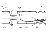
- FIG. 10A is a cross-sectional view of a main part showing the time when the conventional fuel cell is assembled.
- FIG. 10B is a cross-sectional view of a main part showing the time of compression of FIG. 10A.
- FIG. 11A is a cross-sectional view of a main part showing a time when another conventional fuel cell is assembled.
- FIG. 11B is a cross-sectional view of a main part showing the time of compression of FIG. 11A.
- the conventional fuel cell 100 includes a separator 101, a separator 102, and a membrane electrode composite 103.
- the separator 101 arranged on the lower side includes a reaction flow path portion 106 through which the reaction fluid flows, and a convex bead 108 on which the seal member 104 is arranged.
- the separator 102 arranged on the upper side includes a reaction flow path portion 107 through which the reaction fluid flows, and a convex bead 109 on which the seal member 105 is arranged.
- the membrane electrode composite 103 When assembling the fuel cell 100, first, the membrane electrode composite 103 is placed on the lower separator 101. The main body 111 of the membrane electrode composite 103 is placed on the reaction flow path 106, and the overhang (electrolyte film or film) 112 is placed on the seal member 104. The overhanging portion 112 is a portion that overhangs the main body portion 111 to the outside. At this time, a deflection 120 is formed in the overhanging portion 112 between the sealing member 104 and the reaction flow path portion 106 due to its own weight.
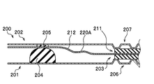
- another conventional fuel cell 200 includes a separator 201, a separator 202, and a membrane electrode composite 203.
- the separator 201 arranged on the lower side includes a sealing member 204 and a reaction flow path portion 206 through which the reaction fluid flows.
- the sealing member 204 is a lip gasket whose diameter decreases toward the tip.
- the separator 202 arranged on the upper side includes a sealing member 205 and a reaction flow path portion 207 through which the reaction fluid flows.
- the membrane electrode composite 203 is arranged on the separator 201.
- the main body 211 of the membrane electrode composite 203 is arranged on the reaction flow path 206, and the overhang (electrolyte film or film) 212 is arranged on the seal member 204.
- a deflection 220 is formed in the overhanging portion 212 between the sealing member 204 and the reaction flow path portion 206 due to its own weight.
- the film electrode composites 103 and 203 have deflections 120 and 220 during assembly, and the deflections 120 and 220 cause wrinkles 120A and 220A during compression. Then it is inferred.
- the overhanging portions 112 and 212 protruding to the outside of the membrane electrode composites 103 and 203 are made of a thin and soft material, bending and wrinkling are likely to occur. Further, when a lip gasket having a large height such as the sealing member 204 is used, the fact that the crushing allowance is set higher also causes the overhanging portions 112 and 212 to bend.
- the present invention has been invented to solve such a problem, and is a method for manufacturing a fuel cell and a fuel cell, which can eliminate or reduce wrinkles of an electrolyte membrane or a film overhanging the outside of a membrane electrode composite.
- the challenge is to provide.
- the present invention for solving the above-mentioned problems includes a seal member arranged in a flatly formed arrangement portion, a one-side separator provided with a reaction flow path portion through which a reaction gas flows, and a seal member arranged in the arrangement portion. And a film electrode composite having a reaction flow path portion through which the reaction gas flows, and a film electrode composite arranged between the one side separator and the other side separator via the seal member, respectively.
- the reaction region is formed by sandwiching the main body of the film electrode composite between the reaction flow paths, and the electrolyte membrane or film protruding from the main body is sandwiched between the sealing members.
- the contact surface of the reaction flow path portion of the one-side separator to which the main body portion of the film electrode composite comes into contact is more than the arrangement surface of the arrangement portion of the one-side separator. It is characterized in that it is set on the side away from the film electrode composite.
- a one-side separator provided with a seal member arranged in a flatly formed arrangement portion and a reaction flow path portion through which the reaction gas flows, and a seal member and the reaction gas arranged in the arrangement portion flow.
- a preparatory step for preparing the other-side separator provided with the reaction flow path portion and the membrane electrode composite, and the membrane electrode composite is arranged on the one-side separator, and the main body portion of the membrane electrode composite is arranged. Is arranged on the reaction flow path portion of the one-side separator, and the electrolyte film or film projecting from the main body portion is arranged on the seal member of the one-side separator.
- the other side separator is arranged on the film electrode composite, the main body portion of the membrane electrode composite is sandwiched between the reaction flow paths, and a reaction region is formed, and the electrolyte membrane is formed between the seal members.
- the other-side separator arranging step of sandwiching the film to form a seal region and a compression step of applying a force in a direction in which the one-side separator and the other-side separator are brought close to each other are included.
- the contact surface of the reaction flow path portion to which the main body portion of the film electrode composite abuts is set to be closer to the side away from the membrane electrode composite than the arrangement surface of the arrangement portion of the one-side separator. It is a feature.
- the difference in height of the overhanging portion (electrolyte film or film) at the time of assembly can be reduced between the seal region and the reaction region.
- the deflection of the overhanging portion can be eliminated or reduced during assembly, and the wrinkles of the overhanging portion of the membrane electrode composite can be eliminated or reduced even after compression.
- the wrinkles of the electrolyte membrane or the film protruding to the outside of the membrane electrode composite can be eliminated or reduced.
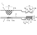
- FIG. 5 is an exploded cross-sectional view of a main part showing a fuel cell according to the first embodiment. It is sectional drawing of the main part which shows the manufacturing method of the fuel cell which concerns on Example 1.
- FIG. FIG. 5 is an exploded cross-sectional view of a main part of the fuel cell according to the first modification of the first embodiment. It is sectional drawing of the main part which shows the manufacturing method of the fuel cell which concerns on modification 1 of Example 1.
- FIG. 5 is an exploded cross-sectional view of a main part showing a fuel cell according to the second embodiment. It is sectional drawing of the main part which shows the manufacturing method of the fuel cell which concerns on Example 2.
- FIG. It is sectional drawing of the main part which shows the time of assembling the conventional fuel cell. It is sectional drawing of the main part which shows the compression time of FIG. 10A. It is sectional drawing of the main part which shows the time of assembling other conventional fuel cell. It is sectional drawing of the main part which shows the compression time of FIG. 11A.
- the fuel cell 1 includes a one-side separator 2, a other-side separator 3, and a membrane electrode composite (MEA: Membrane Electrode Assembly) 4.
- the one-side separator 2 includes a seal member 6 arranged in a flatly formed arrangement portion 5 and a reaction flow path portion 7 through which the reaction gas flows.
- the other side separator 3 includes a seal member 9 arranged in the arrangement portion 8 and a reaction flow path portion 10 through which the reaction gas flows.
- the membrane electrode composite 4 is arranged between the one-side separator 2 and the other-side separator 3 via sealing members 6 and 9, respectively.
- the membrane electrode composite 4 is composed of an electrolyte membrane 11, a pair of catalyst electrode layers (not shown), and a pair of gas diffusion layers 12 and 12.
- the thick portion composed of the electrolyte membrane 11, the pair of catalyst electrode layers and the pair of gas diffusion layers 12 and 12 is referred to as the "main body portion 13", and the electrolyte membrane 11 projecting outward from the main body portion 13 is referred to as the "overhanging portion 14".
- the overhanging portion 14 may be formed of a film.
- the main body 13 of the membrane electrode composite 4 is sandwiched between the reaction flow paths 7 and 10 to form the reaction region 21, and the overhanging portion 14 is sandwiched between the seal members 6 and 9 to form the seal region 22. doing.
- the contact surface 17b of the reaction flow path portion 7 of the one-side separator 2 that abuts on the main body 13 of the membrane electrode composite 4 is set at a position lower than the arrangement surface 5a of the arrangement portion 5 of the one-side separator 2. There is. That is, the contact surface 17b is set on the side away from the film electrode composite 4 with respect to the arrangement surface 5a of the one-side separator 2.
- the contact surface 17b that abuts on the main body 13 of the membrane electrode composite 4 is provided on the one-side separator 2 arrangement portion 5. It is set at a position lower than the arrangement surface 5a.
- the fuel cell 1 is a member that generates electricity by a chemical reaction with hydrogen (fuel gas) supplied from the anode side and oxygen (oxidation gas) supplied from the cathode side.
- the fuel gas and oxidation gas are also collectively referred to as "reaction gas”.
- the fuel cell stack is formed by stacking a plurality of fuel cell cells 1 and compressing them with a predetermined clearance or load between adjacent fuel cell cells 1 and 1.
- the one-side separator 2 is a plate-shaped member arranged under the film electrode composite 4 in this embodiment.
- the one-side separator 2 has an arrangement portion 5 and a reaction flow path portion 7.
- the arrangement portion 5 is a portion where the seal member 6 is arranged, and is formed flat without a convex bead.
- the arranging portion 5 is formed on the surface of the one-side separator 2 facing the film electrode composite 4.
- the arrangement portion 5 has a flat shape without convex beads or the like, but a groove or the like may be formed in a part of the arrangement portion 5 within a range in which the seal member 6 can be arranged flat.
- the seal member 6 is made of an elastic material and is a flat gasket having a rectangular cross section in this embodiment.
- the sealing member 6 may be formed of an elastic material, and for example, ethylene propylene diene rubber (EPDM), silicone rubber (VMQ), fluororubber (FKM), polyisobutylene (PIB), or the like can be used.
- EPDM ethylene propylene diene rubber
- VMQ silicone rubber
- FKM fluororubber
- PIB polyisobutylene
- the seal member 6 can be integrally molded with the one-side separator 2, or can be formed by molding the seal member 6 and then attaching the seal member 6 to the one-side separator 2. Further, the seal member 6 can be integrally molded with the resin reinforcing body with an adhesive and attached to the one-side separator 2.
- the shape of the seal member 6 may be appropriately set, but in this embodiment, it is preferable that the contact surface 6a with which the overhanging portion 14 (electrolyte film 11 or film) abuts is flat.
- a plurality of flow path grooves 17 are formed in the reaction flow path portion 7 in order to widely diffuse the reaction gas in the reaction region.
- a plurality of contact surfaces 17b that come into contact with the main body 13 of the film electrode composite 4 are formed between the adjacent flow path grooves 17 and 17.
- the contact surfaces 17b are formed at the same height position, and are parallel to the arrangement surface 5a of the arrangement portion 5.
- the contact surface 17b is set to be lower than the arrangement surface 5a of the arrangement portion 5 in the thickness direction of the electrolyte membrane 11 (the side away from the electrolyte membrane 11).
- the other side separator 3 is a plate-shaped member arranged on the upper side of the membrane electrode composite 4 in this embodiment.
- the other side separator 3 has an arrangement portion 8 and a reaction flow path portion 10.
- the arrangement portion 8 is a portion where the seal member 9 is arranged, and is formed flat without a convex bead.
- the arrangement portion 8 is formed on a surface facing the film electrode composite 4. Although the arrangement portion 8 is flat in this embodiment, a groove or the like may be formed in a part of the arrangement portion 8.
- the seal member 9 is made of an elastic material, and in this embodiment, it is a lip gasket whose diameter is reduced toward the tip.
- the elastic material of the sealing member 9 is the same as that of the sealing member 6. Further, the molding method of the seal member 9 and the other side separator 3 is the same as that of the seal member 6.
- the shape of the sealing member 9 is not particularly limited as long as it can be sealed so that the reaction gas does not leak.
- a plurality of flow path grooves 18 for widely diffusing the reaction gas into the reaction region are formed in the reaction flow path portion 10.
- a plurality of contact surfaces 18b that come into contact with the main body 13 of the film electrode composite 4 are formed between the adjacent flow path grooves 18 and 18.
- the contact surfaces 18b are formed at the same height position, and are parallel to the arrangement surface 8a of the arrangement portion 8.
- the contact surface 18b is set so as to be lower than the arrangement surface 8a of the arrangement portion 8 (the side close to the electrolyte membrane 11) in the thickness direction of the electrolyte membrane 11. Further, the bottom surface 18a of the flow path groove 18 is formed between the arrangement surface 8a and the contact surface 18b in this embodiment.
- the thickness of the main body 13 of the film electrode composite 4 is sufficiently larger than the thickness of the overhanging portion 14.
- the overhanging portion 14 is formed of an electrolyte membrane 11 or a film.
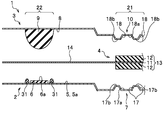
- the main body 13 of the membrane electrode composite 4 is sandwiched between the contact surface 17b of the reaction flow path portion 7 and the contact surface 18b of the reaction flow path portion 10. As a result, a reaction region 21 is formed in which the chemical reaction of the reaction gas is promoted. Further, the overhanging portion 14 of the film electrode composite 4 is sandwiched between the sealing members 6 and 9. As a result, a sealing region 22 in which the reaction gas is sealed is formed.
- the position of the overhanging portion 14 (electrolyte film 11 or film) is substantially the same height between the reaction region 21 and the seal region 22. That is, the overhanging portion 14 is substantially parallel to the arranging portion 5 of the one-side separator 2 between the reaction region 21 and the seal region 22.
- the thickness of the seal member 6 arranged on the one-side separator 2 before assembly is t1
- the crushing allowance of the seal member 6 arranged on the one-side separator 2 is t1 C.
- the height from the contact surface 17b of the reaction flow path portion 7 of the one-side separator 2 to the arrangement surface 5a of the arrangement portion 5 of the one-side separator 2 is defined as t2.
- the thickness dimension of the gas diffusion layer 12 arranged on the one-side separator 2 side before assembly is T GDL, and the crushing allowance dimension of the gas diffusion layer 12 is T C.
- the height dimension from the bottom surface 17a of the flow path groove 17 to the contact surface 17b is t3.
- the height dimension from the bottom surface 17a of the flow path groove 17 to the arrangement surface 5a of the arrangement portion 5 is t4.
- each dimension is set so as to satisfy the following equation (1).
- each dimension may be set so as to satisfy the following formula (2) within a range in which the chemical reaction of the reaction gas is promoted.
- each dimension is set so as to satisfy the following equations (3) and (4).
- equations (1), (2), (3) and (4) are examples, and the dimensions of each part can be appropriately designed.
- the heights t3 and t6 of the flow path grooves 17 and 18 may be appropriately set from the fluidity of the reaction gas (hydrogen, oxygen) and cooling water and the compressibility of the gas diffusion layer 12.
- a preparation step, a membrane electrode composite placement step, a separator placement step on the other side, and a compression step are performed.
- the preparation step is a step of preparing the one-side separator 2, the other-side separator 3, and the film electrode composite 4 described above.
- the membrane electrode composite arranging step is a step of arranging the membrane electrode composite 4 on the one-side separator 2.
- the main body 13 of the membrane electrode composite 4 is arranged on the contact surface 17b of the reaction flow path portion 7, and the overhanging portion 14 is arranged on the contact surface 6a of the seal member 6. At this time, the height position of the overhanging portion 14 (electrolyte film 11 or film) can be made substantially constant.
- the other side separator arranging step is a step of arranging the other side separator 3 on the membrane electrode composite 4.
- the contact surface 18b of the reaction flow path portion 10 is brought into contact with the main body portion 13 of the membrane electrode composite 4, and the overhanging portion 14 is made to face the seal member 6 while facing the seal member 9. Make contact with.
- the compression step a plurality of assembled fuel cell cells 1 are laminated, and a force is applied in a direction in which the one-side separator 2 and the other-side separator 3 are brought close to each other with a predetermined clearance or load to compress the fuel cells.
- the sealing members 6 and 9 are contracted, and the gas diffusion layers 12 and 12 are also contracted.
- the overhanging portion 14 is wrinkle-free and is substantially parallel to the arranging portion 5 of the one-side separator 2.
- the contact surface 17b of the reaction flow path portion 7 is from the arrangement surface 5a of the arrangement portion 5 of the one-side separator 2. Is also set at a low position (a position away from the electrolyte membrane 11).
- the contact surface 6a of the seal member 6 and the contact surface 17b of the flow path groove 17 are provided with a step for absorbing the thickness of the gas diffusion layer 12 of the membrane electrode composite 4.
- the overhanging portions 112 and 212 are bent during assembly, the overhanging portions 112 and 212 are likely to be wrinkled during compression.
- the membrane electrode is used. Since the deflection can be eliminated or reduced in the complex arrangement step, the wrinkles of the overhanging portion 14 can be eliminated or reduced in the fuel cell 1 after the compression step.
- the sum of the crushing allowance t1c of the seal member 6 of the one-side separator 2 and the crushing allowance of the one-side separator 2 (substantially zero because there is no convex bead) in the seal region 22 is the sum of the crushing allowance t1c and the other-side separator. It is set to be smaller than the sum of the crushing allowance t10c of the seal member 9 of 3 and the crushing allowance of the other side separator 3 (substantially zero because there is no convex bead).
- the overhang in the seal region 22 during the compression step is set.
- the displacement of the portion 14 in the height direction (the thickness direction of the electrolyte film 11) can be reduced.
- the wrinkles of the overhanging portion 14 can be eliminated or reduced even during the compression step.
- each member may be appropriately set, but if the conditions are set as in the above formula (1), the height position of the electrolyte membrane 11 on the reaction region 21 side after compression is set. And, the height position of the overhanging portion 14 (electrolyte film 11 or film) on the seal region 22 side can be made substantially the same. As a result, the wrinkles of the overhanging portion 14 can be eliminated or made smaller.
- the height position with respect to the reaction flow path portion 10 side can be easily adjusted while flattening the arrangement portion 8.
- the overhanging portion 14 is prevented from being wrinkled. Can be prevented. Further, by arranging the film electrode composite 4 on the arrangement portion 5 of the one-side separator 2 which is formed flat, the overhanging portion 14 is bent at the time of assembling each member by a simple operation. It is possible to prevent wrinkles from being generated in the overhanging portion 14.
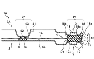
- FIG. 4 is an exploded cross-sectional view of a main part of the fuel cell according to the first modification of the first embodiment.
- FIG. 5 is a cross-sectional view of a main part showing a method of manufacturing a fuel cell according to the first modification of the first embodiment.
- the modification 1 is different from the first embodiment in that the receiving portions 31 and 31 are formed on the one-side separator 2.
- the parts different from the first embodiment will be mainly described.
- the receiving portion 31 is formed on both sides of the seal member 6 in the arranging portion 5 of the one-side separator 2.
- the receiving portion 31 may be formed intermittently or continuously with respect to the extension direction of the seal member 6. Further, the receiving portion 31 may be formed only on one side of the seal member 6.
- the shape of the receiving portion 31 is not particularly limited, but in this modified example, it is formed so as to reduce the diameter toward the tip.
- the height dimension of the receiving portion 31 is set to be larger than the thickness of the seal member 6 before assembly.
- the material of the receiving portion 31 is not particularly limited, and for example, silicone rubber (VMQ), ethylene propylene diene rubber (EPDM), polyisobutylene (PIB), resin and the like can be used.
- the membrane electrode composite 4 is arranged on the one-side separator 2.
- the main body 13 of the membrane electrode composite 4 is arranged on the contact surfaces 17b and 17b of the reaction flow path 7, and the overhanging portion 14 is arranged on the receiving portions 31 and 31.
- the overhanging portion 14 comes into contact with the tips of the receiving portions 31 and 31, but is separated from the contact surface 6a of the seal member 6.
- the separation dimension may be set as appropriate, but is set to, for example, 0.1 mm.
- the gap from the contact surface 6a of the seal member 6 to the overhanging portion 14 is drawn larger than the actual one.
- the overhanging portions 14 come into contact with the sealing members 6 and 9, respectively, as in the first embodiment. Be pinched. Therefore, it is preferable to set the receiving portion 31 to a material, shape, or the like that does not affect the sealing mechanism.
- the sealing member 6 has adhesiveness (tackiness)
- the film electrode composite arranging step and the other side separator arranging step are performed, the overhanging portion 14 and the sealing member 6 stick to each other, and the work It may increase the time and cause bending, wrinkles, etc.
- the overhanging portion 14 and the sealing member 6 are attached to each other before the compression step is performed. It can be prevented from sticking. As a result, even when the seal member 6 has a high tack property, the overhanging portion 14 is difficult to stick to the seal member 6, the assembly becomes easy, and the working time can be shortened. Further, it is possible to prevent the overhanging portion 14 from sticking to the seal member 6 in a state of being bent. Further, if the receiving portion 31 is made of a material having low tackiness, workability can be further improved.
- FIG. 6 is a cross-sectional view of a main part showing a method of manufacturing a fuel cell according to the second modification of the first embodiment.
- the receiving portions 31 and 31 may be provided on the overhanging portion 14 (electrolyte film 11 or film).
- the receiving portions 31 and 31 according to the modified example 2 are formed on the surface of the overhanging portion 14 facing the one-side separator 2.
- the receiving portions 31 and 31 are formed so as to be arranged on both sides of the seal member 6 in the overhanging portion 14.
- the receiving portion 31 may be formed intermittently or continuously with respect to the extension direction of the seal member 6. Further, the receiving portion 31 may be formed so as to be arranged only on one side of the seal member 6.
- the membrane electrode composite 4 is placed on the one-side separator 2 as shown in FIG.
- the main body 13 of the membrane electrode composite 4 is arranged on the contact surfaces 17b and 17b of the reaction flow path portion 7, and the tips of the receiving portions 31 and 31 are brought into contact with the arrangement portion 5 of the one-side separator 2.
- the overhanging portion 14 and the seal member 6 are separated from each other.
- the receiving portions 31 and 31 may be provided in the overhanging portion 14. Even with the configuration of the modified example 2, the same effect as that of the modified example 1 can be obtained.
- FIG. 7 is a cross-sectional view of a main part showing the fuel cell according to the second embodiment.
- the fuel cell 1A according to the second embodiment is mainly different in that the convex bead 41 is provided on the other side separator 3A and that the seal member 42 is used.
- the parts different from the first embodiment will be mainly described.
- the other side separator 3A includes a convex bead 41, a sealing member 42, and a reaction flow path portion 10.
- the convex bead 41 is a portion that protrudes toward the one-side separator 2 side.
- a flat arrangement portion 43 for arranging the seal member 42 is formed.
- the seal member 42 is provided in the arrangement portion 43.
- the sealing member 42 uses a flat gasket having a rectangular cross section.
- FIG. 8 is an exploded cross-sectional view of a main part showing the fuel cell according to the second embodiment.
- the dimensions and conditions of each member are substantially the same as those in the first embodiment.
- the height dimension of the convex bead 41 before assembly is t11, and the crushing allowance of the convex bead 41 is t11c.
- the thickness dimension of the seal member 42 arranged on the other side separator 3A before assembly is t12, and the crushing allowance of the seal member 42 is t12c.
- the method for manufacturing the fuel cell according to the second embodiment will be described.
- the preparatory work step, the membrane electrode composite placement step, the other side separator placement step, and the compression step are performed.
- the preparation step the one-side separator 2, the other-side separator 3A, and the film electrode composite 4 are prepared.
- FIG. 9 is a cross-sectional view of a main part showing a method of manufacturing a fuel cell according to the second embodiment.
- the film electrode composite arrangement step the film electrode composite 4 is arranged on the one-side separator 2 in the same manner as in the first embodiment.
- the other-side separator arranging step the other-side separator 3A is arranged on the membrane electrode composite 4.
- the main body 13 of the membrane electrode composite 4 is sandwiched between the reaction flow paths 7 and 10 to form the reaction region 21, and the overhanging portions 14 are sandwiched between the sealing members 6 and 42. To form the seal region 22.
- the one-side separator 2 and the other-side separator 3A are compressed in a direction in which they are close to each other.
- the sealing members 6 and 42 are compressed, and the convex beads 41 and the gas diffusion layers 12 and 12 are also compressed.
- the overhanging portion 14 is substantially parallel to the arranging portion 5 of the one-side separator 2.
- the fuel cell and the method for manufacturing the fuel cell according to the second embodiment can also achieve substantially the same effect as that of the first embodiment. Further, by providing the convex bead 41 on the other side separator 3A and providing the sealing member 42 on the convex bead 41, the height position with respect to the reaction flow path portion 10 side can be easily adjusted.
- the sum of the crushing allowance t1c of the seal member 6 of the one-side separator 2 and the crushing allowance of the one-side separator 2 (substantially zero because there is no convex bead) in the seal region 22 is the crushing allowance of the convex bead 41 of the other-side separator 3A. It is set smaller than the sum of t11c and the crushing allowance t12c of the seal member 42 (t1c ⁇ (t11c + t12c)).
- the crushing allowance t1c of the seal member 6 of the one-side separator 2 is set to be smaller than the sum of the crushing allowance t11c of the convex bead 41 of the other-side separator 3A and the crushing allowance t12c of the seal member 42, thereby compressing.
- the displacement of the overhanging portion 14 in the sealing region 22 during the process in the height direction (thickness direction of the electrolyte film 11) can be reduced.
- the wrinkles of the overhanging portion 14 can be eliminated or reduced even during the compression step.
- the design can be appropriately modified without being limited to the above-described configuration.
- the receiving portion 31 can also be provided in the embodiment of the second embodiment.
Abstract
La présente invention est caractérisée par : le fait de comprendre un séparateur d'un côté (2), un séparateur d'autre côté (3) et un ensemble membrane-électrode (4) agencés avec des éléments d'étanchéité respectifs (6, 9) entre ceux-ci ; le fait de former une région de réaction (21) et une région d'étanchéité (22) ; et le fait qu'une surface de contact (17b), qui est la partie d'une section de passage d'écoulement de réaction (7) du séparateur d'un côté (2) qui entre en butée avec une section de corps principal (13) de l'ensemble membrane-électrode (4), est réglée de manière à être davantage séparée de l'ensemble membrane-électrode (4) qu'une surface de placement (5a) d'une section de placement (5) du séparateur d'un côté (2).
Priority Applications (1)
| Application Number | Priority Date | Filing Date | Title |
|---|---|---|---|
| JP2021536840A JP7181409B2 (ja) | 2019-07-30 | 2020-06-24 | 燃料電池セル及び燃料電池セルの製造方法 |
Applications Claiming Priority (2)
| Application Number | Priority Date | Filing Date | Title |
|---|---|---|---|
| JP2019-139383 | 2019-07-30 | ||
| JP2019139383 | 2019-07-30 |
Publications (1)
| Publication Number | Publication Date |
|---|---|
| WO2021019974A1 true WO2021019974A1 (fr) | 2021-02-04 |
Family
ID=74229854
Family Applications (1)
| Application Number | Title | Priority Date | Filing Date |
|---|---|---|---|
| PCT/JP2020/024777 WO2021019974A1 (fr) | 2019-07-30 | 2020-06-24 | Pile à combustible et procédé de fabrication de pile à combustible |
Country Status (2)
| Country | Link |
|---|---|
| JP (1) | JP7181409B2 (fr) |
| WO (1) | WO2021019974A1 (fr) |
Citations (5)
| Publication number | Priority date | Publication date | Assignee | Title |
|---|---|---|---|---|
| JPH0615402Y2 (ja) * | 1986-08-08 | 1994-04-20 | 石川島播磨重工業株式会社 | 燃料電池 |
| JP2006156216A (ja) * | 2004-11-30 | 2006-06-15 | Nissan Motor Co Ltd | 燃料電池 |
| JP2007005210A (ja) * | 2005-06-27 | 2007-01-11 | Toyota Motor Corp | 燃料電池及び燃料電池スタック |
| JP2007035296A (ja) * | 2005-07-22 | 2007-02-08 | Nissan Motor Co Ltd | 電解質膜/電極積層体および燃料電池セル |
| JP2018125258A (ja) * | 2017-02-03 | 2018-08-09 | 本田技研工業株式会社 | 燃料電池用金属セパレータ及び発電セル |
-
2020
- 2020-06-24 WO PCT/JP2020/024777 patent/WO2021019974A1/fr active Application Filing
- 2020-06-24 JP JP2021536840A patent/JP7181409B2/ja active Active
Patent Citations (5)
| Publication number | Priority date | Publication date | Assignee | Title |
|---|---|---|---|---|
| JPH0615402Y2 (ja) * | 1986-08-08 | 1994-04-20 | 石川島播磨重工業株式会社 | 燃料電池 |
| JP2006156216A (ja) * | 2004-11-30 | 2006-06-15 | Nissan Motor Co Ltd | 燃料電池 |
| JP2007005210A (ja) * | 2005-06-27 | 2007-01-11 | Toyota Motor Corp | 燃料電池及び燃料電池スタック |
| JP2007035296A (ja) * | 2005-07-22 | 2007-02-08 | Nissan Motor Co Ltd | 電解質膜/電極積層体および燃料電池セル |
| JP2018125258A (ja) * | 2017-02-03 | 2018-08-09 | 本田技研工業株式会社 | 燃料電池用金属セパレータ及び発電セル |
Also Published As
| Publication number | Publication date |
|---|---|
| JPWO2021019974A1 (fr) | 2021-02-04 |
| JP7181409B2 (ja) | 2022-11-30 |
Similar Documents
| Publication | Publication Date | Title |
|---|---|---|
| JP5186754B2 (ja) | 燃料電池 | |
| KR101763662B1 (ko) | 고체 고분자 전해질 연료 전지를 위한 시일 | |
| CN113036175B (zh) | 隔板的制造方法 | |
| JP2002042838A (ja) | 燃料電池、多孔質導電体・シール構造体の製造方法及び電極膜構造体の製造方法 | |
| CA2989526C (fr) | Structure d'electrode de pile a combustible, separateur metallique, pile a combustible utilisant ladite structure d'electrode de pile a combustible et ledit separateur metallique,et matrice de fabrication de ladite structure d'electrode de pile a combustible | |
| US9470314B2 (en) | Rubber gasket for fuel cell | |
| JP7428514B2 (ja) | 燃料電池用接合セパレータの製造方法 | |
| JP4581702B2 (ja) | 燃料電池 | |
| WO2021019974A1 (fr) | Pile à combustible et procédé de fabrication de pile à combustible | |
| JP4998656B2 (ja) | 燃料電池セルの密封構造 | |
| JP2008146872A (ja) | 燃料電池および燃料電池の製造方法 | |
| TW202127719A (zh) | 用於燃料電池之膜電極組的密封結構及其製造方法 | |
| JP6628166B2 (ja) | 燃料電池スタック | |
| KR101197596B1 (ko) | 연로전지용 가스켓 및 이를 구비하는 연료전지 | |
| JP2008123885A (ja) | 燃料電池、燃料電池の製造方法、および、アッセンブリ | |
| JP7309596B2 (ja) | 燃料電池用接合セパレータ | |
| CN113097527B (zh) | 燃料电池用接合隔板的制造方法 | |
| JPH06119928A (ja) | 固体高分子電解質燃料電池スタック | |
| JP7236913B2 (ja) | 燃料電池用分離板組立体およびこれを含む燃料電池スタック | |
| JP6544229B2 (ja) | 燃料電池セル | |
| JP2004241167A (ja) | 燃料電池用構成部品 | |
| JP2021118109A (ja) | 燃料電池のシール構造 | |
| JP2014165040A (ja) | 高分子電解質型燃料電池用の電極―膜―枠接合体の構造およびその製造方法、並びに高分子電解質型燃料電池 |
Legal Events
| Date | Code | Title | Description |
|---|---|---|---|
| 121 | Ep: the epo has been informed by wipo that ep was designated in this application |
Ref document number: 20847931 Country of ref document: EP Kind code of ref document: A1 |
|
| ENP | Entry into the national phase |
Ref document number: 2021536840 Country of ref document: JP Kind code of ref document: A |
|
| NENP | Non-entry into the national phase |
Ref country code: DE |
|
| 122 | Ep: pct application non-entry in european phase |
Ref document number: 20847931 Country of ref document: EP Kind code of ref document: A1 |