WO2021019974A1 - Fuel cell and method for manufacturing fuel cell - Google Patents
Fuel cell and method for manufacturing fuel cell Download PDFInfo
- Publication number
- WO2021019974A1 WO2021019974A1 PCT/JP2020/024777 JP2020024777W WO2021019974A1 WO 2021019974 A1 WO2021019974 A1 WO 2021019974A1 JP 2020024777 W JP2020024777 W JP 2020024777W WO 2021019974 A1 WO2021019974 A1 WO 2021019974A1
- Authority
- WO
- WIPO (PCT)
- Prior art keywords
- side separator
- electrode composite
- separator
- fuel cell
- membrane electrode
- Prior art date
Links
Images


Classifications
-
- F—MECHANICAL ENGINEERING; LIGHTING; HEATING; WEAPONS; BLASTING
- F16—ENGINEERING ELEMENTS AND UNITS; GENERAL MEASURES FOR PRODUCING AND MAINTAINING EFFECTIVE FUNCTIONING OF MACHINES OR INSTALLATIONS; THERMAL INSULATION IN GENERAL
- F16J—PISTONS; CYLINDERS; SEALINGS
- F16J15/00—Sealings
- F16J15/02—Sealings between relatively-stationary surfaces
- F16J15/06—Sealings between relatively-stationary surfaces with solid packing compressed between sealing surfaces
- F16J15/10—Sealings between relatively-stationary surfaces with solid packing compressed between sealing surfaces with non-metallic packing
- F16J15/12—Sealings between relatively-stationary surfaces with solid packing compressed between sealing surfaces with non-metallic packing with metal reinforcement or covering
-
- H—ELECTRICITY
- H01—ELECTRIC ELEMENTS
- H01M—PROCESSES OR MEANS, e.g. BATTERIES, FOR THE DIRECT CONVERSION OF CHEMICAL ENERGY INTO ELECTRICAL ENERGY
- H01M8/00—Fuel cells; Manufacture thereof
- H01M8/02—Details
-
- H—ELECTRICITY
- H01—ELECTRIC ELEMENTS
- H01M—PROCESSES OR MEANS, e.g. BATTERIES, FOR THE DIRECT CONVERSION OF CHEMICAL ENERGY INTO ELECTRICAL ENERGY
- H01M8/00—Fuel cells; Manufacture thereof
- H01M8/02—Details
- H01M8/0202—Collectors; Separators, e.g. bipolar separators; Interconnectors
- H01M8/0258—Collectors; Separators, e.g. bipolar separators; Interconnectors characterised by the configuration of channels, e.g. by the flow field of the reactant or coolant
-
- H—ELECTRICITY
- H01—ELECTRIC ELEMENTS
- H01M—PROCESSES OR MEANS, e.g. BATTERIES, FOR THE DIRECT CONVERSION OF CHEMICAL ENERGY INTO ELECTRICAL ENERGY
- H01M8/00—Fuel cells; Manufacture thereof
- H01M8/02—Details
- H01M8/0271—Sealing or supporting means around electrodes, matrices or membranes
-
- H—ELECTRICITY
- H01—ELECTRIC ELEMENTS
- H01M—PROCESSES OR MEANS, e.g. BATTERIES, FOR THE DIRECT CONVERSION OF CHEMICAL ENERGY INTO ELECTRICAL ENERGY
- H01M8/00—Fuel cells; Manufacture thereof
- H01M8/02—Details
- H01M8/0271—Sealing or supporting means around electrodes, matrices or membranes
- H01M8/0286—Processes for forming seals
-
- H—ELECTRICITY
- H01—ELECTRIC ELEMENTS
- H01M—PROCESSES OR MEANS, e.g. BATTERIES, FOR THE DIRECT CONVERSION OF CHEMICAL ENERGY INTO ELECTRICAL ENERGY
- H01M8/00—Fuel cells; Manufacture thereof
- H01M8/10—Fuel cells with solid electrolytes
-
- Y—GENERAL TAGGING OF NEW TECHNOLOGICAL DEVELOPMENTS; GENERAL TAGGING OF CROSS-SECTIONAL TECHNOLOGIES SPANNING OVER SEVERAL SECTIONS OF THE IPC; TECHNICAL SUBJECTS COVERED BY FORMER USPC CROSS-REFERENCE ART COLLECTIONS [XRACs] AND DIGESTS
- Y02—TECHNOLOGIES OR APPLICATIONS FOR MITIGATION OR ADAPTATION AGAINST CLIMATE CHANGE
- Y02E—REDUCTION OF GREENHOUSE GAS [GHG] EMISSIONS, RELATED TO ENERGY GENERATION, TRANSMISSION OR DISTRIBUTION
- Y02E60/00—Enabling technologies; Technologies with a potential or indirect contribution to GHG emissions mitigation
- Y02E60/30—Hydrogen technology
- Y02E60/50—Fuel cells
-
- Y—GENERAL TAGGING OF NEW TECHNOLOGICAL DEVELOPMENTS; GENERAL TAGGING OF CROSS-SECTIONAL TECHNOLOGIES SPANNING OVER SEVERAL SECTIONS OF THE IPC; TECHNICAL SUBJECTS COVERED BY FORMER USPC CROSS-REFERENCE ART COLLECTIONS [XRACs] AND DIGESTS
- Y02—TECHNOLOGIES OR APPLICATIONS FOR MITIGATION OR ADAPTATION AGAINST CLIMATE CHANGE
- Y02P—CLIMATE CHANGE MITIGATION TECHNOLOGIES IN THE PRODUCTION OR PROCESSING OF GOODS
- Y02P70/00—Climate change mitigation technologies in the production process for final industrial or consumer products
- Y02P70/50—Manufacturing or production processes characterised by the final manufactured product
Definitions
- the present invention relates to a fuel cell and a method for manufacturing a fuel cell.
- a fuel cell is composed of a membrane electrode assembly (MEA: Membrane Electrode Assembly), a pair of separators sandwiching the membrane electrode composite, and a pair of separators and a membrane electrode composite. It is provided with a sealing member, which is interposed between them.
- the membrane electrode composite comprises an electrolyte membrane, a pair of catalyst electrode layers and a pair of gas diffusion layers.
- the portion where the catalyst electrode layer and the gas diffusion layer are formed is referred to as a "main body portion”
- the electrolyte membrane or film protruding outward from the main body portion is referred to as an "overhanging portion".
- the sealing member is, for example, an elastic body, a gasket, or the like.
- the main body of the membrane electrode composite is sandwiched between the reaction flow paths provided in the pair of separators to form a reaction region.
- the overhanging portion of the film electrode composite is sandwiched between the sealing members provided on the pair of separators to form a sealing region.
- the fuel cell stack is formed by stacking a plurality of fuel cell cells and compressing the fuel cell cells with a predetermined clearance or load. When the fuel cell is compressed, the membrane electrode composite is also compressed via the sealing member, but it is desirable that no wrinkles are generated in the overhanging portion between the sealing region and the reaction region.
- FIG. 10A is a cross-sectional view of a main part showing the time when the conventional fuel cell is assembled.
- FIG. 10B is a cross-sectional view of a main part showing the time of compression of FIG. 10A.
- FIG. 11A is a cross-sectional view of a main part showing a time when another conventional fuel cell is assembled.
- FIG. 11B is a cross-sectional view of a main part showing the time of compression of FIG. 11A.
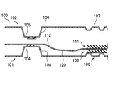
- the conventional fuel cell 100 includes a separator 101, a separator 102, and a membrane electrode composite 103.
- the separator 101 arranged on the lower side includes a reaction flow path portion 106 through which the reaction fluid flows, and a convex bead 108 on which the seal member 104 is arranged.
- the separator 102 arranged on the upper side includes a reaction flow path portion 107 through which the reaction fluid flows, and a convex bead 109 on which the seal member 105 is arranged.
- the membrane electrode composite 103 When assembling the fuel cell 100, first, the membrane electrode composite 103 is placed on the lower separator 101. The main body 111 of the membrane electrode composite 103 is placed on the reaction flow path 106, and the overhang (electrolyte film or film) 112 is placed on the seal member 104. The overhanging portion 112 is a portion that overhangs the main body portion 111 to the outside. At this time, a deflection 120 is formed in the overhanging portion 112 between the sealing member 104 and the reaction flow path portion 106 due to its own weight.
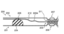
- another conventional fuel cell 200 includes a separator 201, a separator 202, and a membrane electrode composite 203.
- the separator 201 arranged on the lower side includes a sealing member 204 and a reaction flow path portion 206 through which the reaction fluid flows.
- the sealing member 204 is a lip gasket whose diameter decreases toward the tip.
- the separator 202 arranged on the upper side includes a sealing member 205 and a reaction flow path portion 207 through which the reaction fluid flows.
- the membrane electrode composite 203 is arranged on the separator 201.
- the main body 211 of the membrane electrode composite 203 is arranged on the reaction flow path 206, and the overhang (electrolyte film or film) 212 is arranged on the seal member 204.
- a deflection 220 is formed in the overhanging portion 212 between the sealing member 204 and the reaction flow path portion 206 due to its own weight.
- the film electrode composites 103 and 203 have deflections 120 and 220 during assembly, and the deflections 120 and 220 cause wrinkles 120A and 220A during compression. Then it is inferred.
- the overhanging portions 112 and 212 protruding to the outside of the membrane electrode composites 103 and 203 are made of a thin and soft material, bending and wrinkling are likely to occur. Further, when a lip gasket having a large height such as the sealing member 204 is used, the fact that the crushing allowance is set higher also causes the overhanging portions 112 and 212 to bend.
- the present invention has been invented to solve such a problem, and is a method for manufacturing a fuel cell and a fuel cell, which can eliminate or reduce wrinkles of an electrolyte membrane or a film overhanging the outside of a membrane electrode composite.
- the challenge is to provide.
- the present invention for solving the above-mentioned problems includes a seal member arranged in a flatly formed arrangement portion, a one-side separator provided with a reaction flow path portion through which a reaction gas flows, and a seal member arranged in the arrangement portion. And a film electrode composite having a reaction flow path portion through which the reaction gas flows, and a film electrode composite arranged between the one side separator and the other side separator via the seal member, respectively.
- the reaction region is formed by sandwiching the main body of the film electrode composite between the reaction flow paths, and the electrolyte membrane or film protruding from the main body is sandwiched between the sealing members.
- the contact surface of the reaction flow path portion of the one-side separator to which the main body portion of the film electrode composite comes into contact is more than the arrangement surface of the arrangement portion of the one-side separator. It is characterized in that it is set on the side away from the film electrode composite.
- a one-side separator provided with a seal member arranged in a flatly formed arrangement portion and a reaction flow path portion through which the reaction gas flows, and a seal member and the reaction gas arranged in the arrangement portion flow.
- a preparatory step for preparing the other-side separator provided with the reaction flow path portion and the membrane electrode composite, and the membrane electrode composite is arranged on the one-side separator, and the main body portion of the membrane electrode composite is arranged. Is arranged on the reaction flow path portion of the one-side separator, and the electrolyte film or film projecting from the main body portion is arranged on the seal member of the one-side separator.
- the other side separator is arranged on the film electrode composite, the main body portion of the membrane electrode composite is sandwiched between the reaction flow paths, and a reaction region is formed, and the electrolyte membrane is formed between the seal members.
- the other-side separator arranging step of sandwiching the film to form a seal region and a compression step of applying a force in a direction in which the one-side separator and the other-side separator are brought close to each other are included.
- the contact surface of the reaction flow path portion to which the main body portion of the film electrode composite abuts is set to be closer to the side away from the membrane electrode composite than the arrangement surface of the arrangement portion of the one-side separator. It is a feature.
- the difference in height of the overhanging portion (electrolyte film or film) at the time of assembly can be reduced between the seal region and the reaction region.
- the deflection of the overhanging portion can be eliminated or reduced during assembly, and the wrinkles of the overhanging portion of the membrane electrode composite can be eliminated or reduced even after compression.
- the wrinkles of the electrolyte membrane or the film protruding to the outside of the membrane electrode composite can be eliminated or reduced.
- FIG. 5 is an exploded cross-sectional view of a main part showing a fuel cell according to the first embodiment. It is sectional drawing of the main part which shows the manufacturing method of the fuel cell which concerns on Example 1.
- FIG. FIG. 5 is an exploded cross-sectional view of a main part of the fuel cell according to the first modification of the first embodiment. It is sectional drawing of the main part which shows the manufacturing method of the fuel cell which concerns on modification 1 of Example 1.
- FIG. 5 is an exploded cross-sectional view of a main part showing a fuel cell according to the second embodiment. It is sectional drawing of the main part which shows the manufacturing method of the fuel cell which concerns on Example 2.
- FIG. It is sectional drawing of the main part which shows the time of assembling the conventional fuel cell. It is sectional drawing of the main part which shows the compression time of FIG. 10A. It is sectional drawing of the main part which shows the time of assembling other conventional fuel cell. It is sectional drawing of the main part which shows the compression time of FIG. 11A.
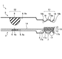
- the fuel cell 1 includes a one-side separator 2, a other-side separator 3, and a membrane electrode composite (MEA: Membrane Electrode Assembly) 4.
- the one-side separator 2 includes a seal member 6 arranged in a flatly formed arrangement portion 5 and a reaction flow path portion 7 through which the reaction gas flows.
- the other side separator 3 includes a seal member 9 arranged in the arrangement portion 8 and a reaction flow path portion 10 through which the reaction gas flows.
- the membrane electrode composite 4 is arranged between the one-side separator 2 and the other-side separator 3 via sealing members 6 and 9, respectively.
- the membrane electrode composite 4 is composed of an electrolyte membrane 11, a pair of catalyst electrode layers (not shown), and a pair of gas diffusion layers 12 and 12.
- the thick portion composed of the electrolyte membrane 11, the pair of catalyst electrode layers and the pair of gas diffusion layers 12 and 12 is referred to as the "main body portion 13", and the electrolyte membrane 11 projecting outward from the main body portion 13 is referred to as the "overhanging portion 14".
- the overhanging portion 14 may be formed of a film.
- the main body 13 of the membrane electrode composite 4 is sandwiched between the reaction flow paths 7 and 10 to form the reaction region 21, and the overhanging portion 14 is sandwiched between the seal members 6 and 9 to form the seal region 22. doing.
- the contact surface 17b of the reaction flow path portion 7 of the one-side separator 2 that abuts on the main body 13 of the membrane electrode composite 4 is set at a position lower than the arrangement surface 5a of the arrangement portion 5 of the one-side separator 2. There is. That is, the contact surface 17b is set on the side away from the film electrode composite 4 with respect to the arrangement surface 5a of the one-side separator 2.
- the contact surface 17b that abuts on the main body 13 of the membrane electrode composite 4 is provided on the one-side separator 2 arrangement portion 5. It is set at a position lower than the arrangement surface 5a.
- the fuel cell 1 is a member that generates electricity by a chemical reaction with hydrogen (fuel gas) supplied from the anode side and oxygen (oxidation gas) supplied from the cathode side.
- the fuel gas and oxidation gas are also collectively referred to as "reaction gas”.
- the fuel cell stack is formed by stacking a plurality of fuel cell cells 1 and compressing them with a predetermined clearance or load between adjacent fuel cell cells 1 and 1.
- the one-side separator 2 is a plate-shaped member arranged under the film electrode composite 4 in this embodiment.
- the one-side separator 2 has an arrangement portion 5 and a reaction flow path portion 7.
- the arrangement portion 5 is a portion where the seal member 6 is arranged, and is formed flat without a convex bead.
- the arranging portion 5 is formed on the surface of the one-side separator 2 facing the film electrode composite 4.
- the arrangement portion 5 has a flat shape without convex beads or the like, but a groove or the like may be formed in a part of the arrangement portion 5 within a range in which the seal member 6 can be arranged flat.
- the seal member 6 is made of an elastic material and is a flat gasket having a rectangular cross section in this embodiment.
- the sealing member 6 may be formed of an elastic material, and for example, ethylene propylene diene rubber (EPDM), silicone rubber (VMQ), fluororubber (FKM), polyisobutylene (PIB), or the like can be used.
- EPDM ethylene propylene diene rubber
- VMQ silicone rubber
- FKM fluororubber
- PIB polyisobutylene
- the seal member 6 can be integrally molded with the one-side separator 2, or can be formed by molding the seal member 6 and then attaching the seal member 6 to the one-side separator 2. Further, the seal member 6 can be integrally molded with the resin reinforcing body with an adhesive and attached to the one-side separator 2.
- the shape of the seal member 6 may be appropriately set, but in this embodiment, it is preferable that the contact surface 6a with which the overhanging portion 14 (electrolyte film 11 or film) abuts is flat.
- a plurality of flow path grooves 17 are formed in the reaction flow path portion 7 in order to widely diffuse the reaction gas in the reaction region.
- a plurality of contact surfaces 17b that come into contact with the main body 13 of the film electrode composite 4 are formed between the adjacent flow path grooves 17 and 17.
- the contact surfaces 17b are formed at the same height position, and are parallel to the arrangement surface 5a of the arrangement portion 5.
- the contact surface 17b is set to be lower than the arrangement surface 5a of the arrangement portion 5 in the thickness direction of the electrolyte membrane 11 (the side away from the electrolyte membrane 11).
- the other side separator 3 is a plate-shaped member arranged on the upper side of the membrane electrode composite 4 in this embodiment.
- the other side separator 3 has an arrangement portion 8 and a reaction flow path portion 10.
- the arrangement portion 8 is a portion where the seal member 9 is arranged, and is formed flat without a convex bead.
- the arrangement portion 8 is formed on a surface facing the film electrode composite 4. Although the arrangement portion 8 is flat in this embodiment, a groove or the like may be formed in a part of the arrangement portion 8.
- the seal member 9 is made of an elastic material, and in this embodiment, it is a lip gasket whose diameter is reduced toward the tip.
- the elastic material of the sealing member 9 is the same as that of the sealing member 6. Further, the molding method of the seal member 9 and the other side separator 3 is the same as that of the seal member 6.
- the shape of the sealing member 9 is not particularly limited as long as it can be sealed so that the reaction gas does not leak.
- a plurality of flow path grooves 18 for widely diffusing the reaction gas into the reaction region are formed in the reaction flow path portion 10.
- a plurality of contact surfaces 18b that come into contact with the main body 13 of the film electrode composite 4 are formed between the adjacent flow path grooves 18 and 18.
- the contact surfaces 18b are formed at the same height position, and are parallel to the arrangement surface 8a of the arrangement portion 8.
- the contact surface 18b is set so as to be lower than the arrangement surface 8a of the arrangement portion 8 (the side close to the electrolyte membrane 11) in the thickness direction of the electrolyte membrane 11. Further, the bottom surface 18a of the flow path groove 18 is formed between the arrangement surface 8a and the contact surface 18b in this embodiment.
- the thickness of the main body 13 of the film electrode composite 4 is sufficiently larger than the thickness of the overhanging portion 14.
- the overhanging portion 14 is formed of an electrolyte membrane 11 or a film.
- the main body 13 of the membrane electrode composite 4 is sandwiched between the contact surface 17b of the reaction flow path portion 7 and the contact surface 18b of the reaction flow path portion 10. As a result, a reaction region 21 is formed in which the chemical reaction of the reaction gas is promoted. Further, the overhanging portion 14 of the film electrode composite 4 is sandwiched between the sealing members 6 and 9. As a result, a sealing region 22 in which the reaction gas is sealed is formed.
- the position of the overhanging portion 14 (electrolyte film 11 or film) is substantially the same height between the reaction region 21 and the seal region 22. That is, the overhanging portion 14 is substantially parallel to the arranging portion 5 of the one-side separator 2 between the reaction region 21 and the seal region 22.
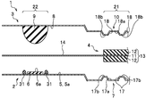
- the thickness of the seal member 6 arranged on the one-side separator 2 before assembly is t1
- the crushing allowance of the seal member 6 arranged on the one-side separator 2 is t1 C.
- the height from the contact surface 17b of the reaction flow path portion 7 of the one-side separator 2 to the arrangement surface 5a of the arrangement portion 5 of the one-side separator 2 is defined as t2.
- the thickness dimension of the gas diffusion layer 12 arranged on the one-side separator 2 side before assembly is T GDL, and the crushing allowance dimension of the gas diffusion layer 12 is T C.
- the height dimension from the bottom surface 17a of the flow path groove 17 to the contact surface 17b is t3.
- the height dimension from the bottom surface 17a of the flow path groove 17 to the arrangement surface 5a of the arrangement portion 5 is t4.
- each dimension is set so as to satisfy the following equation (1).
- each dimension may be set so as to satisfy the following formula (2) within a range in which the chemical reaction of the reaction gas is promoted.
- each dimension is set so as to satisfy the following equations (3) and (4).
- equations (1), (2), (3) and (4) are examples, and the dimensions of each part can be appropriately designed.
- the heights t3 and t6 of the flow path grooves 17 and 18 may be appropriately set from the fluidity of the reaction gas (hydrogen, oxygen) and cooling water and the compressibility of the gas diffusion layer 12.
- a preparation step, a membrane electrode composite placement step, a separator placement step on the other side, and a compression step are performed.
- the preparation step is a step of preparing the one-side separator 2, the other-side separator 3, and the film electrode composite 4 described above.
- the membrane electrode composite arranging step is a step of arranging the membrane electrode composite 4 on the one-side separator 2.
- the main body 13 of the membrane electrode composite 4 is arranged on the contact surface 17b of the reaction flow path portion 7, and the overhanging portion 14 is arranged on the contact surface 6a of the seal member 6. At this time, the height position of the overhanging portion 14 (electrolyte film 11 or film) can be made substantially constant.
- the other side separator arranging step is a step of arranging the other side separator 3 on the membrane electrode composite 4.
- the contact surface 18b of the reaction flow path portion 10 is brought into contact with the main body portion 13 of the membrane electrode composite 4, and the overhanging portion 14 is made to face the seal member 6 while facing the seal member 9. Make contact with.
- the compression step a plurality of assembled fuel cell cells 1 are laminated, and a force is applied in a direction in which the one-side separator 2 and the other-side separator 3 are brought close to each other with a predetermined clearance or load to compress the fuel cells.
- the sealing members 6 and 9 are contracted, and the gas diffusion layers 12 and 12 are also contracted.
- the overhanging portion 14 is wrinkle-free and is substantially parallel to the arranging portion 5 of the one-side separator 2.
- the contact surface 17b of the reaction flow path portion 7 is from the arrangement surface 5a of the arrangement portion 5 of the one-side separator 2. Is also set at a low position (a position away from the electrolyte membrane 11).
- the contact surface 6a of the seal member 6 and the contact surface 17b of the flow path groove 17 are provided with a step for absorbing the thickness of the gas diffusion layer 12 of the membrane electrode composite 4.
- the overhanging portions 112 and 212 are bent during assembly, the overhanging portions 112 and 212 are likely to be wrinkled during compression.
- the membrane electrode is used. Since the deflection can be eliminated or reduced in the complex arrangement step, the wrinkles of the overhanging portion 14 can be eliminated or reduced in the fuel cell 1 after the compression step.
- the sum of the crushing allowance t1c of the seal member 6 of the one-side separator 2 and the crushing allowance of the one-side separator 2 (substantially zero because there is no convex bead) in the seal region 22 is the sum of the crushing allowance t1c and the other-side separator. It is set to be smaller than the sum of the crushing allowance t10c of the seal member 9 of 3 and the crushing allowance of the other side separator 3 (substantially zero because there is no convex bead).
- the overhang in the seal region 22 during the compression step is set.
- the displacement of the portion 14 in the height direction (the thickness direction of the electrolyte film 11) can be reduced.
- the wrinkles of the overhanging portion 14 can be eliminated or reduced even during the compression step.
- each member may be appropriately set, but if the conditions are set as in the above formula (1), the height position of the electrolyte membrane 11 on the reaction region 21 side after compression is set. And, the height position of the overhanging portion 14 (electrolyte film 11 or film) on the seal region 22 side can be made substantially the same. As a result, the wrinkles of the overhanging portion 14 can be eliminated or made smaller.
- the height position with respect to the reaction flow path portion 10 side can be easily adjusted while flattening the arrangement portion 8.
- the overhanging portion 14 is prevented from being wrinkled. Can be prevented. Further, by arranging the film electrode composite 4 on the arrangement portion 5 of the one-side separator 2 which is formed flat, the overhanging portion 14 is bent at the time of assembling each member by a simple operation. It is possible to prevent wrinkles from being generated in the overhanging portion 14.
- FIG. 4 is an exploded cross-sectional view of a main part of the fuel cell according to the first modification of the first embodiment.
- FIG. 5 is a cross-sectional view of a main part showing a method of manufacturing a fuel cell according to the first modification of the first embodiment.
- the modification 1 is different from the first embodiment in that the receiving portions 31 and 31 are formed on the one-side separator 2.
- the parts different from the first embodiment will be mainly described.
- the receiving portion 31 is formed on both sides of the seal member 6 in the arranging portion 5 of the one-side separator 2.
- the receiving portion 31 may be formed intermittently or continuously with respect to the extension direction of the seal member 6. Further, the receiving portion 31 may be formed only on one side of the seal member 6.
- the shape of the receiving portion 31 is not particularly limited, but in this modified example, it is formed so as to reduce the diameter toward the tip.
- the height dimension of the receiving portion 31 is set to be larger than the thickness of the seal member 6 before assembly.
- the material of the receiving portion 31 is not particularly limited, and for example, silicone rubber (VMQ), ethylene propylene diene rubber (EPDM), polyisobutylene (PIB), resin and the like can be used.
- the membrane electrode composite 4 is arranged on the one-side separator 2.
- the main body 13 of the membrane electrode composite 4 is arranged on the contact surfaces 17b and 17b of the reaction flow path 7, and the overhanging portion 14 is arranged on the receiving portions 31 and 31.
- the overhanging portion 14 comes into contact with the tips of the receiving portions 31 and 31, but is separated from the contact surface 6a of the seal member 6.
- the separation dimension may be set as appropriate, but is set to, for example, 0.1 mm.
- the gap from the contact surface 6a of the seal member 6 to the overhanging portion 14 is drawn larger than the actual one.
- the overhanging portions 14 come into contact with the sealing members 6 and 9, respectively, as in the first embodiment. Be pinched. Therefore, it is preferable to set the receiving portion 31 to a material, shape, or the like that does not affect the sealing mechanism.
- the sealing member 6 has adhesiveness (tackiness)
- the film electrode composite arranging step and the other side separator arranging step are performed, the overhanging portion 14 and the sealing member 6 stick to each other, and the work It may increase the time and cause bending, wrinkles, etc.
- the overhanging portion 14 and the sealing member 6 are attached to each other before the compression step is performed. It can be prevented from sticking. As a result, even when the seal member 6 has a high tack property, the overhanging portion 14 is difficult to stick to the seal member 6, the assembly becomes easy, and the working time can be shortened. Further, it is possible to prevent the overhanging portion 14 from sticking to the seal member 6 in a state of being bent. Further, if the receiving portion 31 is made of a material having low tackiness, workability can be further improved.
- FIG. 6 is a cross-sectional view of a main part showing a method of manufacturing a fuel cell according to the second modification of the first embodiment.
- the receiving portions 31 and 31 may be provided on the overhanging portion 14 (electrolyte film 11 or film).
- the receiving portions 31 and 31 according to the modified example 2 are formed on the surface of the overhanging portion 14 facing the one-side separator 2.
- the receiving portions 31 and 31 are formed so as to be arranged on both sides of the seal member 6 in the overhanging portion 14.
- the receiving portion 31 may be formed intermittently or continuously with respect to the extension direction of the seal member 6. Further, the receiving portion 31 may be formed so as to be arranged only on one side of the seal member 6.
- the membrane electrode composite 4 is placed on the one-side separator 2 as shown in FIG.
- the main body 13 of the membrane electrode composite 4 is arranged on the contact surfaces 17b and 17b of the reaction flow path portion 7, and the tips of the receiving portions 31 and 31 are brought into contact with the arrangement portion 5 of the one-side separator 2.
- the overhanging portion 14 and the seal member 6 are separated from each other.
- the receiving portions 31 and 31 may be provided in the overhanging portion 14. Even with the configuration of the modified example 2, the same effect as that of the modified example 1 can be obtained.
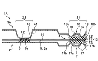
- FIG. 7 is a cross-sectional view of a main part showing the fuel cell according to the second embodiment.
- the fuel cell 1A according to the second embodiment is mainly different in that the convex bead 41 is provided on the other side separator 3A and that the seal member 42 is used.
- the parts different from the first embodiment will be mainly described.
- the other side separator 3A includes a convex bead 41, a sealing member 42, and a reaction flow path portion 10.
- the convex bead 41 is a portion that protrudes toward the one-side separator 2 side.
- a flat arrangement portion 43 for arranging the seal member 42 is formed.
- the seal member 42 is provided in the arrangement portion 43.
- the sealing member 42 uses a flat gasket having a rectangular cross section.
- FIG. 8 is an exploded cross-sectional view of a main part showing the fuel cell according to the second embodiment.
- the dimensions and conditions of each member are substantially the same as those in the first embodiment.
- the height dimension of the convex bead 41 before assembly is t11, and the crushing allowance of the convex bead 41 is t11c.
- the thickness dimension of the seal member 42 arranged on the other side separator 3A before assembly is t12, and the crushing allowance of the seal member 42 is t12c.
- the method for manufacturing the fuel cell according to the second embodiment will be described.
- the preparatory work step, the membrane electrode composite placement step, the other side separator placement step, and the compression step are performed.
- the preparation step the one-side separator 2, the other-side separator 3A, and the film electrode composite 4 are prepared.
- FIG. 9 is a cross-sectional view of a main part showing a method of manufacturing a fuel cell according to the second embodiment.
- the film electrode composite arrangement step the film electrode composite 4 is arranged on the one-side separator 2 in the same manner as in the first embodiment.
- the other-side separator arranging step the other-side separator 3A is arranged on the membrane electrode composite 4.
- the main body 13 of the membrane electrode composite 4 is sandwiched between the reaction flow paths 7 and 10 to form the reaction region 21, and the overhanging portions 14 are sandwiched between the sealing members 6 and 42. To form the seal region 22.
- the one-side separator 2 and the other-side separator 3A are compressed in a direction in which they are close to each other.
- the sealing members 6 and 42 are compressed, and the convex beads 41 and the gas diffusion layers 12 and 12 are also compressed.
- the overhanging portion 14 is substantially parallel to the arranging portion 5 of the one-side separator 2.
- the fuel cell and the method for manufacturing the fuel cell according to the second embodiment can also achieve substantially the same effect as that of the first embodiment. Further, by providing the convex bead 41 on the other side separator 3A and providing the sealing member 42 on the convex bead 41, the height position with respect to the reaction flow path portion 10 side can be easily adjusted.
- the sum of the crushing allowance t1c of the seal member 6 of the one-side separator 2 and the crushing allowance of the one-side separator 2 (substantially zero because there is no convex bead) in the seal region 22 is the crushing allowance of the convex bead 41 of the other-side separator 3A. It is set smaller than the sum of t11c and the crushing allowance t12c of the seal member 42 (t1c ⁇ (t11c + t12c)).
- the crushing allowance t1c of the seal member 6 of the one-side separator 2 is set to be smaller than the sum of the crushing allowance t11c of the convex bead 41 of the other-side separator 3A and the crushing allowance t12c of the seal member 42, thereby compressing.
- the displacement of the overhanging portion 14 in the sealing region 22 during the process in the height direction (thickness direction of the electrolyte film 11) can be reduced.
- the wrinkles of the overhanging portion 14 can be eliminated or reduced even during the compression step.
- the design can be appropriately modified without being limited to the above-described configuration.
- the receiving portion 31 can also be provided in the embodiment of the second embodiment.
Abstract
The present invention is characterized by: having a one-side separator (2), an other-side separator (3), and a membrane electrode assembly (4) arranged with respective seal members (6, 9) therebetween; forming a reaction region (21) and a seal region (22); and a contact surface (17b), which is the portion of a reaction flow passage section (7) of the one-side separator (2) that is abutted by a main body section (13) of the membrane electrode assembly (4), being set so as to be further separated from the membrane electrode assembly (4) than a placement surface (5a) of a placement section (5) of the one-side separator (2).
Description
本発明は、燃料電池セル及び燃料電池セルの製造方法に関する。
The present invention relates to a fuel cell and a method for manufacturing a fuel cell.
燃料電池セルは、例えば、特許文献1に示すように、膜電極複合体(MEA:Membrane Electrode Assembly)と、膜電極複合体を挟持する一対のセパレータと、一対のセパレータと膜電極複合体との間にそれぞれ介設されるシール部材と、を備えている。膜電極複合体は、電解質膜、一対の触媒電極層及び一対のガス拡散層を備えている。ここで、膜電極複合体のうち、触媒電極層及びガス拡散層が形成されている部位を「本体部」とし、当該本体部から外側に張り出す電解質膜又はフィルムを「張出部」とする。シール部材は、例えば、弾性体やガスケット等である。
As shown in Patent Document 1, for example, a fuel cell is composed of a membrane electrode assembly (MEA: Membrane Electrode Assembly), a pair of separators sandwiching the membrane electrode composite, and a pair of separators and a membrane electrode composite. It is provided with a sealing member, which is interposed between them. The membrane electrode composite comprises an electrolyte membrane, a pair of catalyst electrode layers and a pair of gas diffusion layers. Here, in the membrane electrode composite, the portion where the catalyst electrode layer and the gas diffusion layer are formed is referred to as a "main body portion", and the electrolyte membrane or film protruding outward from the main body portion is referred to as an "overhanging portion". .. The sealing member is, for example, an elastic body, a gasket, or the like.
膜電極複合体の本体部は、一対のセパレータに設けられた反応流路部同士に挟持されて反応領域を形成する。膜電極複合体の張出部は、一対のセパレータに設けられたシール部材同士に挟持されてシール領域を形成する。燃料電池スタックは、燃料電池セルを複数個積層させ、燃料電池セル間で所定のクリアランス又は荷重で圧縮して構成される。燃料電池セルが圧縮される際、膜電極複合体もシール部材を介して圧縮されるが、シール領域と反応領域の間の張出部にしわが発生しないことが望ましい。
The main body of the membrane electrode composite is sandwiched between the reaction flow paths provided in the pair of separators to form a reaction region. The overhanging portion of the film electrode composite is sandwiched between the sealing members provided on the pair of separators to form a sealing region. The fuel cell stack is formed by stacking a plurality of fuel cell cells and compressing the fuel cell cells with a predetermined clearance or load. When the fuel cell is compressed, the membrane electrode composite is also compressed via the sealing member, but it is desirable that no wrinkles are generated in the overhanging portion between the sealing region and the reaction region.
図10Aは、従来の燃料電池セルの組付け時を示す要部断面図である。図10Bは、図10Aの圧縮時を示す要部断面図である。図11Aは、従来の他の燃料電池セルの組付け時を示す要部断面図である。図11Bは、図11Aの圧縮時を示す要部断面図である。
FIG. 10A is a cross-sectional view of a main part showing the time when the conventional fuel cell is assembled. FIG. 10B is a cross-sectional view of a main part showing the time of compression of FIG. 10A. FIG. 11A is a cross-sectional view of a main part showing a time when another conventional fuel cell is assembled. FIG. 11B is a cross-sectional view of a main part showing the time of compression of FIG. 11A.
図10Aに示すように、従来の燃料電池セル100は、セパレータ101と、セパレータ102と、膜電極複合体103と、を備えている。下側に配置されるセパレータ101は、反応流体が流通する反応流路部106と、シール部材104が配置される凸ビード108とを備えている。上側に配置されるセパレータ102は、反応流体が流通する反応流路部107と、シール部材105が配置される凸ビード109とを備えている。
As shown in FIG. 10A, the conventional fuel cell 100 includes a separator 101, a separator 102, and a membrane electrode composite 103. The separator 101 arranged on the lower side includes a reaction flow path portion 106 through which the reaction fluid flows, and a convex bead 108 on which the seal member 104 is arranged. The separator 102 arranged on the upper side includes a reaction flow path portion 107 through which the reaction fluid flows, and a convex bead 109 on which the seal member 105 is arranged.
燃料電池セル100を組み付ける際は、まず、下側のセパレータ101の上に、膜電極複合体103を配置する。膜電極複合体103の本体部111を反応流路部106の上に配置し、張出部(電解質膜又はフィルム)112をシール部材104の上に配置する。張出部112は、本体部111よりも外側に張り出す部位である。このとき、シール部材104と反応流路部106との間において、張出部112にはその自重によりたわみ120が形成される。
When assembling the fuel cell 100, first, the membrane electrode composite 103 is placed on the lower separator 101. The main body 111 of the membrane electrode composite 103 is placed on the reaction flow path 106, and the overhang (electrolyte film or film) 112 is placed on the seal member 104. The overhanging portion 112 is a portion that overhangs the main body portion 111 to the outside. At this time, a deflection 120 is formed in the overhanging portion 112 between the sealing member 104 and the reaction flow path portion 106 due to its own weight.
図10Bに示すように、セパレータ101,102同士を近接させる方向に力を付与すると、シール領域では凸ビード108,109がそれぞれ高さ方向に収縮するとともに、シール部材104,105も収縮する。また、反応領域では、膜電極複合体103の本体部111のガス拡散層が収縮する。これにより、シール領域の張出部112の高さ位置と、反応領域での電解質膜の高さ位置は概ね同一となる。一方、張出部112においては、シール領域と反応領域の間にしわ120Aが発生するおそれがある。
As shown in FIG. 10B, when a force is applied in the direction in which the separators 101 and 102 are brought close to each other, the convex beads 108 and 109 contract in the height direction and the seal members 104 and 105 also contract in the seal region. Further, in the reaction region, the gas diffusion layer of the main body 111 of the membrane electrode composite 103 shrinks. As a result, the height position of the overhanging portion 112 in the seal region and the height position of the electrolyte membrane in the reaction region are substantially the same. On the other hand, in the overhanging portion 112, wrinkles 120A may occur between the seal region and the reaction region.
図11Aに示すように、従来の他の燃料電池セル200は、セパレータ201と、セパレータ202と、膜電極複合体203と、を備えている。下側に配置されるセパレータ201は、シール部材204及び反応流体が流通する反応流路部206を備えている。シール部材204は、先端に向かうにつれて縮径するリップガスケットである。上側に配置されるセパレータ202は、シール部材205及び反応流体が流通する反応流路部207を備えている。
As shown in FIG. 11A, another conventional fuel cell 200 includes a separator 201, a separator 202, and a membrane electrode composite 203. The separator 201 arranged on the lower side includes a sealing member 204 and a reaction flow path portion 206 through which the reaction fluid flows. The sealing member 204 is a lip gasket whose diameter decreases toward the tip. The separator 202 arranged on the upper side includes a sealing member 205 and a reaction flow path portion 207 through which the reaction fluid flows.
燃料電池セル200を組み付ける際には、まず、セパレータ201の上に、膜電極複合体203を配置する。膜電極複合体203の本体部211は反応流路部206の上に配置し、張出部(電解質膜又はフィルム)212はシール部材204の上に配置する。このとき、シール部材204と反応流路部206との間において、張出部212にはその自重によりたわみ220が形成されている。
When assembling the fuel cell 200, first, the membrane electrode composite 203 is arranged on the separator 201. The main body 211 of the membrane electrode composite 203 is arranged on the reaction flow path 206, and the overhang (electrolyte film or film) 212 is arranged on the seal member 204. At this time, a deflection 220 is formed in the overhanging portion 212 between the sealing member 204 and the reaction flow path portion 206 due to its own weight.
図11Bに示すように、セパレータ201,202同士を近接させる方向に力を付与すると、シール領域ではシール部材204及びシール部材205は高さ方向に収縮する。また、反応領域では、膜電極複合体203の本体部211のガス拡散層が収縮する。一方、張出部212においては、シール領域と反応領域の間にしわ220Aが発生するおそれがある。
As shown in FIG. 11B, when a force is applied in the direction in which the separators 201 and 202 are brought close to each other, the seal member 204 and the seal member 205 contract in the height direction in the seal region. Further, in the reaction region, the gas diffusion layer of the main body 211 of the membrane electrode composite 203 shrinks. On the other hand, in the overhanging portion 212, wrinkles 220A may occur between the seal region and the reaction region.
膜電極複合体103,203の外側に張り出す張出部(本体部の外側に張り出す電解質膜又はフィルム)112,212にはしわが発生しないことが望ましい。しかしながら、燃料電池セル100,200は、いずれも組付け時に膜電極複合体103,203にたわみ120,220が発生しており、当該たわみ120,220に起因して圧縮時にしわ120A,220Aが発生すると推察される。
It is desirable that wrinkles do not occur on the overhanging portions (electrolyte film or film overhanging the outside of the main body portion) 112 and 212 that overhang the membrane electrode composites 103 and 203. However, in each of the fuel cell cells 100 and 200, the film electrode composites 103 and 203 have deflections 120 and 220 during assembly, and the deflections 120 and 220 cause wrinkles 120A and 220A during compression. Then it is inferred.
また、膜電極複合体103,203の外側に張り出す張出部112,212は、薄くかつ柔らかい材料で形成されているため、たわみやしわが発生しやすい。さらに、シール部材204のように高さの大きいリップガスケットを用いる場合、つぶし代分高く設定されていることも張出部112,212のたわみの要因となる。
Further, since the overhanging portions 112 and 212 protruding to the outside of the membrane electrode composites 103 and 203 are made of a thin and soft material, bending and wrinkling are likely to occur. Further, when a lip gasket having a large height such as the sealing member 204 is used, the fact that the crushing allowance is set higher also causes the overhanging portions 112 and 212 to bend.
本発明はかかる課題を解決するために発明されたものであり、膜電極複合体の外側に張り出す電解質膜又はフィルムのしわを無くすか、小さくことができる燃料電池セル及び燃料電池セルの製造方法を提供することを課題とする。
The present invention has been invented to solve such a problem, and is a method for manufacturing a fuel cell and a fuel cell, which can eliminate or reduce wrinkles of an electrolyte membrane or a film overhanging the outside of a membrane electrode composite. The challenge is to provide.
前記課題を解決するための本発明は、平坦に形成された配置部に配置されたシール部材及び反応ガスが流通する反応流路部を備えた一方側セパレータと、配置部に配置されたシール部材及び反応ガスが流通する反応流路部を備えた他方側セパレータと、前記一方側セパレータと前記他方側セパレータとの間にそれぞれ前記シール部材を介して配置された膜電極複合体と、を有し、前記膜電極複合体の本体部が反応流路部同士に挟持されることにより反応領域が形成されているとともに、前記本体部から張り出した電解質膜又はフィルムが前記シール部材同士に挟持されることによりシール領域が形成され、前記一方側セパレータの前記反応流路部のうち前記膜電極複合体の前記本体部が当接する当接面は、前記一方側セパレータの前記配置部の配置面よりも前記膜電極複合体から離間する側に設定されていることを特徴とする。
The present invention for solving the above-mentioned problems includes a seal member arranged in a flatly formed arrangement portion, a one-side separator provided with a reaction flow path portion through which a reaction gas flows, and a seal member arranged in the arrangement portion. And a film electrode composite having a reaction flow path portion through which the reaction gas flows, and a film electrode composite arranged between the one side separator and the other side separator via the seal member, respectively. The reaction region is formed by sandwiching the main body of the film electrode composite between the reaction flow paths, and the electrolyte membrane or film protruding from the main body is sandwiched between the sealing members. The contact surface of the reaction flow path portion of the one-side separator to which the main body portion of the film electrode composite comes into contact is more than the arrangement surface of the arrangement portion of the one-side separator. It is characterized in that it is set on the side away from the film electrode composite.
また、本発明は、平坦に形成された配置部に配置されたシール部材及び反応ガスが流通する反応流路部を備えた一方側セパレータと、配置部に配置されたシール部材及び反応ガスが流通する反応流路部を備えた他方側セパレータと、膜電極複合体と、を準備する準備工程と、前記一方側セパレータの上に前記膜電極複合体を配置し、前記膜電極複合体の本体部を前記一方側セパレータの前記反応流路部の上に配置するとともに、前記本体部から張り出した電解質膜又はフィルムを前記一方側セパレータの前記シール部材の上に配置する膜電極複合体配置工程と、前記膜電極複合体の上に前記他方側セパレータを配置し、前記反応流路部同士で前記膜電極複合体の本体部を挟持して反応領域を形成するとともに、前記シール部材同士で前記電解質膜又はフィルムを挟持してシール領域を形成する他方側セパレータ配置工程と、前記一方側セパレータと前記他方側セパレータとを近接させる方向に力を付与する圧縮工程と、を含み、前記一方側セパレータの前記反応流路部のうち前記膜電極複合体の前記本体部が当接する当接面を、前記一方側セパレータの前記配置部の配置面よりも前記膜電極複合体から離間する側に設定することを特徴とする。
Further, in the present invention, a one-side separator provided with a seal member arranged in a flatly formed arrangement portion and a reaction flow path portion through which the reaction gas flows, and a seal member and the reaction gas arranged in the arrangement portion flow. A preparatory step for preparing the other-side separator provided with the reaction flow path portion and the membrane electrode composite, and the membrane electrode composite is arranged on the one-side separator, and the main body portion of the membrane electrode composite is arranged. Is arranged on the reaction flow path portion of the one-side separator, and the electrolyte film or film projecting from the main body portion is arranged on the seal member of the one-side separator. The other side separator is arranged on the film electrode composite, the main body portion of the membrane electrode composite is sandwiched between the reaction flow paths, and a reaction region is formed, and the electrolyte membrane is formed between the seal members. Alternatively, the other-side separator arranging step of sandwiching the film to form a seal region and a compression step of applying a force in a direction in which the one-side separator and the other-side separator are brought close to each other are included. The contact surface of the reaction flow path portion to which the main body portion of the film electrode composite abuts is set to be closer to the side away from the membrane electrode composite than the arrangement surface of the arrangement portion of the one-side separator. It is a feature.
かかる構成によれば、シール領域と反応領域の間において、組付け時の張出部(電解質膜又はフィルム)の高さの差を小さくすることができる。これにより、組付け時に張出部のたわみを無くすか、小さくすることができ、圧縮後においても膜電極複合体の張出部のしわを無くすか、小さくすることができる。
According to such a configuration, the difference in height of the overhanging portion (electrolyte film or film) at the time of assembly can be reduced between the seal region and the reaction region. As a result, the deflection of the overhanging portion can be eliminated or reduced during assembly, and the wrinkles of the overhanging portion of the membrane electrode composite can be eliminated or reduced even after compression.
本発明の燃料電池セル及び燃料電池セルの製造方法によれば、膜電極複合体の外側に張り出す電解質膜又はフィルムのしわを無くすか、小さくすることができる。
According to the fuel cell and the method for manufacturing a fuel cell of the present invention, the wrinkles of the electrolyte membrane or the film protruding to the outside of the membrane electrode composite can be eliminated or reduced.
図1に示すように、本実施形態に係る燃料電池セル1は、一方側セパレータ2と、他方側セパレータ3と、膜電極複合体(MEA:Membrane Electrode Assembly)4とを備えている。一方側セパレータ2は、平坦に形成された配置部5に配置されたシール部材6及び反応ガスが流通する反応流路部7を備えている。他方側セパレータ3は、配置部8に配置されたシール部材9及び反応ガスが流通する反応流路部10を備えている。
As shown in FIG. 1, the fuel cell 1 according to the present embodiment includes a one-side separator 2, a other-side separator 3, and a membrane electrode composite (MEA: Membrane Electrode Assembly) 4. The one-side separator 2 includes a seal member 6 arranged in a flatly formed arrangement portion 5 and a reaction flow path portion 7 through which the reaction gas flows. The other side separator 3 includes a seal member 9 arranged in the arrangement portion 8 and a reaction flow path portion 10 through which the reaction gas flows.
膜電極複合体4は、一方側セパレータ2と他方側セパレータ3との間にそれぞれシール部材6,9を介して配置されている。膜電極複合体4は、電解質膜11、一対の触媒電極層(図示省略)及び一対のガス拡散層12,12で構成されている。電解質膜11、一対の触媒電極層及び一対のガス拡散層12,12で構成される厚い部位を「本体部13」とし、本体部13から外側に張り出す電解質膜11を「張出部14」とする。張出部14は、フィルムで形成されている場合もある。
The membrane electrode composite 4 is arranged between the one-side separator 2 and the other-side separator 3 via sealing members 6 and 9, respectively. The membrane electrode composite 4 is composed of an electrolyte membrane 11, a pair of catalyst electrode layers (not shown), and a pair of gas diffusion layers 12 and 12. The thick portion composed of the electrolyte membrane 11, the pair of catalyst electrode layers and the pair of gas diffusion layers 12 and 12 is referred to as the "main body portion 13", and the electrolyte membrane 11 projecting outward from the main body portion 13 is referred to as the "overhanging portion 14". And. The overhanging portion 14 may be formed of a film.
膜電極複合体4の本体部13が反応流路部7,10同士に挟持されて反応領域21を形成するとともに、張出部14がシール部材6,9同士に挟持されてシール領域22を形成している。一方側セパレータ2の反応流路部7のうち膜電極複合体4の本体部13に当接する当接面17bは、一方側セパレータ2の配置部5の配置面5aよりも低い位置に設定されている。つまり、当接面17bは、一方側セパレータ2の配置面5aよりも膜電極複合体4から離間する側に設定されている。
The main body 13 of the membrane electrode composite 4 is sandwiched between the reaction flow paths 7 and 10 to form the reaction region 21, and the overhanging portion 14 is sandwiched between the seal members 6 and 9 to form the seal region 22. doing. The contact surface 17b of the reaction flow path portion 7 of the one-side separator 2 that abuts on the main body 13 of the membrane electrode composite 4 is set at a position lower than the arrangement surface 5a of the arrangement portion 5 of the one-side separator 2. There is. That is, the contact surface 17b is set on the side away from the film electrode composite 4 with respect to the arrangement surface 5a of the one-side separator 2.
図3に示すように、本実施形態の燃料電池セル及び燃料電池セルの製造方法では、膜電極複合体4の本体部13に当接する当接面17bを、一方側セパレータ2の配置部5の配置面5aよりも低い位置に設定している。これにより、一方側セパレータ2の上に膜電極複合体4を配置したときに、張出部14(電解質膜11又はフィルム)を概ね平坦にすることができる。また、圧縮時においても張出部14の高さ方向の変位を少なくすることができる。これにより、燃料電池セル1を組み付ける際に、反応領域21とシール領域22との間の張出部14のたわみを無くすか、小さくすることができ、圧縮後においても、張出部14のしわを無くすか、小さくすることができる。以下、実施例について詳細に説明する。
As shown in FIG. 3, in the fuel cell and the fuel cell manufacturing method of the present embodiment, the contact surface 17b that abuts on the main body 13 of the membrane electrode composite 4 is provided on the one-side separator 2 arrangement portion 5. It is set at a position lower than the arrangement surface 5a. As a result, when the membrane electrode composite 4 is arranged on the one-side separator 2, the overhanging portion 14 (electrolyte film 11 or film) can be made substantially flat. Further, the displacement of the overhanging portion 14 in the height direction can be reduced even during compression. As a result, when the fuel cell 1 is assembled, the deflection of the overhanging portion 14 between the reaction region 21 and the sealing region 22 can be eliminated or reduced, and the wrinkles of the overhanging portion 14 can be reduced even after compression. Can be eliminated or reduced. Hereinafter, examples will be described in detail.
[実施例1]
図1に示すように、燃料電池セル1は、アノード側より供給される水素(燃料ガス)、カソード側より供給される酸素(酸化ガス)との化学反応により発電する部材である。前記燃料ガス及び酸化ガスを総称して「反応ガス」とも言う。燃料電池スタックは、燃料電池セル1を複数個積層させ、隣り合う燃料電池セル1,1間で所定のクリアランス又は荷重で圧縮することで形成される。 [Example 1]
As shown in FIG. 1, thefuel cell 1 is a member that generates electricity by a chemical reaction with hydrogen (fuel gas) supplied from the anode side and oxygen (oxidation gas) supplied from the cathode side. The fuel gas and oxidation gas are also collectively referred to as "reaction gas". The fuel cell stack is formed by stacking a plurality of fuel cell cells 1 and compressing them with a predetermined clearance or load between adjacent fuel cell cells 1 and 1.
図1に示すように、燃料電池セル1は、アノード側より供給される水素(燃料ガス)、カソード側より供給される酸素(酸化ガス)との化学反応により発電する部材である。前記燃料ガス及び酸化ガスを総称して「反応ガス」とも言う。燃料電池スタックは、燃料電池セル1を複数個積層させ、隣り合う燃料電池セル1,1間で所定のクリアランス又は荷重で圧縮することで形成される。 [Example 1]
As shown in FIG. 1, the
一方側セパレータ2は、本実施例では膜電極複合体4の下側に配置される板状部材である。一方側セパレータ2は、配置部5と、反応流路部7とを有する。配置部5は、シール部材6が配置される部位であり、凸ビードが無く平坦に形成されている。配置部5は、一方側セパレータ2のうち膜電極複合体4に対向する面に形成されている。配置部5は、本実施例では凸ビード等が無い平坦な形状になっているが、シール部材6を平坦に配置できる範囲で配置部5の一部に溝等が形成されていてもよい。
The one-side separator 2 is a plate-shaped member arranged under the film electrode composite 4 in this embodiment. The one-side separator 2 has an arrangement portion 5 and a reaction flow path portion 7. The arrangement portion 5 is a portion where the seal member 6 is arranged, and is formed flat without a convex bead. The arranging portion 5 is formed on the surface of the one-side separator 2 facing the film electrode composite 4. In the present embodiment, the arrangement portion 5 has a flat shape without convex beads or the like, but a groove or the like may be formed in a part of the arrangement portion 5 within a range in which the seal member 6 can be arranged flat.
シール部材6は、弾性材料で形成されており、本実施例では断面矩形のフラットガスケットである。シール部材6は、弾性を有する材料で形成すればよく、例えば、エチレンプロピレンジエンゴム(EPDM)、シリコーンゴム(VMQ)、フッ素ゴム(FKM)、ポリイソブチレン(PIB)等を用いることができる。
The seal member 6 is made of an elastic material and is a flat gasket having a rectangular cross section in this embodiment. The sealing member 6 may be formed of an elastic material, and for example, ethylene propylene diene rubber (EPDM), silicone rubber (VMQ), fluororubber (FKM), polyisobutylene (PIB), or the like can be used.
シール部材6は、一方側セパレータ2に一体成形されるか、又は、シール部材6を成形した後、当該シール部材6を一方側セパレータ2に貼り付けて形成することができる。また、粘着剤付きの樹脂補強体にシール部材6を一体成形して一方側セパレータ2に貼り付けることもできる。シール部材6の形状は、適宜設定すればよいが、本実施例では張出部14(電解質膜11又はフィルム)が当接する当接面6aが平坦であることが好ましい。
The seal member 6 can be integrally molded with the one-side separator 2, or can be formed by molding the seal member 6 and then attaching the seal member 6 to the one-side separator 2. Further, the seal member 6 can be integrally molded with the resin reinforcing body with an adhesive and attached to the one-side separator 2. The shape of the seal member 6 may be appropriately set, but in this embodiment, it is preferable that the contact surface 6a with which the overhanging portion 14 (electrolyte film 11 or film) abuts is flat.
反応流路部7には、反応ガスを反応領域に広く拡散させるために複数の流路溝17が形成されている。隣り合う流路溝17,17の間には、膜電極複合体4の本体部13に当接する複数の当接面17bが形成されている。当接面17bは、それぞれ同じ高さ位置に形成されており、配置部5の配置面5aと平行になっている。当接面17bは、電解質膜11の厚さ方向において配置部5の配置面5aよりも低くなる(電解質膜11から離間する側)ように設定されている。
A plurality of flow path grooves 17 are formed in the reaction flow path portion 7 in order to widely diffuse the reaction gas in the reaction region. A plurality of contact surfaces 17b that come into contact with the main body 13 of the film electrode composite 4 are formed between the adjacent flow path grooves 17 and 17. The contact surfaces 17b are formed at the same height position, and are parallel to the arrangement surface 5a of the arrangement portion 5. The contact surface 17b is set to be lower than the arrangement surface 5a of the arrangement portion 5 in the thickness direction of the electrolyte membrane 11 (the side away from the electrolyte membrane 11).
他方側セパレータ3は、本実施例では膜電極複合体4の上側に配置される板状部材である。他方側セパレータ3は、配置部8と、反応流路部10とを有する。配置部8は、シール部材9が配置される部位であり、凸ビードが無く平坦に形成されている。配置部8は、膜電極複合体4に対向する面に形成されている。配置部8は、本実施例では平坦になっているが、配置部8の一部に溝等が形成されていてもよい。
The other side separator 3 is a plate-shaped member arranged on the upper side of the membrane electrode composite 4 in this embodiment. The other side separator 3 has an arrangement portion 8 and a reaction flow path portion 10. The arrangement portion 8 is a portion where the seal member 9 is arranged, and is formed flat without a convex bead. The arrangement portion 8 is formed on a surface facing the film electrode composite 4. Although the arrangement portion 8 is flat in this embodiment, a groove or the like may be formed in a part of the arrangement portion 8.
シール部材9は、弾性材料で形成されており、本実施例では先端に向けて縮径するリップガスケットである。シール部材9の弾性材料はシール部材6と同じである。また、シール部材9と他方側セパレータ3との成形方法もシール部材6と同じである。シール部材9の形状は、反応ガスが遺漏しないようにシール可能であれば特に制限されない。
The seal member 9 is made of an elastic material, and in this embodiment, it is a lip gasket whose diameter is reduced toward the tip. The elastic material of the sealing member 9 is the same as that of the sealing member 6. Further, the molding method of the seal member 9 and the other side separator 3 is the same as that of the seal member 6. The shape of the sealing member 9 is not particularly limited as long as it can be sealed so that the reaction gas does not leak.
反応流路部10には、反応ガスを反応領域に広く拡散させるための複数の流路溝18が形成されている。隣り合う流路溝18,18の間には、膜電極複合体4の本体部13に当接する複数の当接面18bが形成されている。当接面18bは、それぞれ同じ高さ位置に形成されており、配置部8の配置面8aと平行になっている。当接面18bは、電解質膜11の厚さ方向において配置部8の配置面8aよりも低い位置(電解質膜11に近接する側)となるように設定されている。また、流路溝18の底面18aは、本実施例では、配置面8aと当接面18bの間に形成されている。
A plurality of flow path grooves 18 for widely diffusing the reaction gas into the reaction region are formed in the reaction flow path portion 10. A plurality of contact surfaces 18b that come into contact with the main body 13 of the film electrode composite 4 are formed between the adjacent flow path grooves 18 and 18. The contact surfaces 18b are formed at the same height position, and are parallel to the arrangement surface 8a of the arrangement portion 8. The contact surface 18b is set so as to be lower than the arrangement surface 8a of the arrangement portion 8 (the side close to the electrolyte membrane 11) in the thickness direction of the electrolyte membrane 11. Further, the bottom surface 18a of the flow path groove 18 is formed between the arrangement surface 8a and the contact surface 18b in this embodiment.
膜電極複合体4の本体部13の厚さは、張出部14の厚さに対して十分に大きくなっている。張出部14は、電解質膜11又はフィルムで形成されている。
The thickness of the main body 13 of the film electrode composite 4 is sufficiently larger than the thickness of the overhanging portion 14. The overhanging portion 14 is formed of an electrolyte membrane 11 or a film.
膜電極複合体4の本体部13は、反応流路部7の当接面17bと、反応流路部10の当接面18bとで挟持される。これにより、反応ガスの化学反応が促進される反応領域21が形成される。また、膜電極複合体4の張出部14は、シール部材6,9で挟持される。これにより、反応ガスがシールされるシール領域22が形成される。張出部14(電解質膜11又はフィルム)の位置は、反応領域21とシール領域22との間で概ね同じ高さ位置になっている。つまり、張出部14は、反応領域21とシール領域22との間で、一方側セパレータ2の配置部5と概ね平行になっている。
The main body 13 of the membrane electrode composite 4 is sandwiched between the contact surface 17b of the reaction flow path portion 7 and the contact surface 18b of the reaction flow path portion 10. As a result, a reaction region 21 is formed in which the chemical reaction of the reaction gas is promoted. Further, the overhanging portion 14 of the film electrode composite 4 is sandwiched between the sealing members 6 and 9. As a result, a sealing region 22 in which the reaction gas is sealed is formed. The position of the overhanging portion 14 (electrolyte film 11 or film) is substantially the same height between the reaction region 21 and the seal region 22. That is, the overhanging portion 14 is substantially parallel to the arranging portion 5 of the one-side separator 2 between the reaction region 21 and the seal region 22.
図2に示すように、組付け前の一方側セパレータ2に配置されるシール部材6の厚さをt1とし、一方側セパレータ2に配置されるシール部材6のつぶし代をt1Cとする。また、一方側セパレータ2の反応流路部7の当接面17bから一方側セパレータ2の配置部5の配置面5aまでの高さをt2とする。
As shown in FIG. 2, the thickness of the seal member 6 arranged on the one-side separator 2 before assembly is t1, and the crushing allowance of the seal member 6 arranged on the one-side separator 2 is t1 C. Further, the height from the contact surface 17b of the reaction flow path portion 7 of the one-side separator 2 to the arrangement surface 5a of the arrangement portion 5 of the one-side separator 2 is defined as t2.
また、一方側セパレータ2側に配置されたガス拡散層12の組付け前の厚さ寸法をTGDLとし、当該ガス拡散層12のつぶし代寸法をTCとする。また、流路溝17の底面17aから当接面17bまでの高さ寸法をt3とする。また、流路溝17の底面17aから、配置部5の配置面5aまでの高さ寸法をt4とする。このとき、本実施例では、下記の式(1)を満たすように各寸法が設定されている。
Further, the thickness dimension of the gas diffusion layer 12 arranged on the one-side separator 2 side before assembly is T GDL, and the crushing allowance dimension of the gas diffusion layer 12 is T C. Further, the height dimension from the bottom surface 17a of the flow path groove 17 to the contact surface 17b is t3. Further, the height dimension from the bottom surface 17a of the flow path groove 17 to the arrangement surface 5a of the arrangement portion 5 is t4. At this time, in this embodiment, each dimension is set so as to satisfy the following equation (1).
(t1-t1C)+t2=(TGDL-TC) 式(1)
(T1-t1 C ) + t2 = ( TGDL - TC ) Equation (1)
なお、張出部14を平坦に設計することは困難であるため、反応ガスの化学反応が促進される範囲で下記の式(2)を満たすように各寸法を設定してもよい。
Since it is difficult to design the overhanging portion 14 to be flat, each dimension may be set so as to satisfy the following formula (2) within a range in which the chemical reaction of the reaction gas is promoted.
(t1-t1C)+t2=(TGDL-TC)×α 式(2)
α=0.8~1.2 (T1-t1 C ) + t2 = ( TGDL - TC ) × α equation (2)
α = 0.8-1.2
α=0.8~1.2 (T1-t1 C ) + t2 = ( TGDL - TC ) × α equation (2)
α = 0.8-1.2
また、他方側セパレータ3の流路溝18の底面18aから当接面18bまでの高さ寸法をt6とし、配置部8の配置面8aから底面18aまでの高さ寸法をt7とし、配置部8の配置面8aから当接面18bまでの高さ寸法をt8とする。また、組付け前の他方側セパレータ3に配置されるシール部材9の厚さ寸法をt10とし、他方側セパレータ3に配置されるシール部材9のつぶし代をt10cとする。このとき、本実施例では下記の式(3)、式(4)を満たすように各寸法が設定されている。
Further, the height dimension from the bottom surface 18a of the flow path groove 18 of the other side separator 3 to the contact surface 18b is t6, and the height dimension from the arrangement surface 8a to the bottom surface 18a of the arrangement portion 8 is t7. The height dimension from the arrangement surface 8a to the contact surface 18b is t8. Further, the thickness dimension of the seal member 9 arranged on the other side separator 3 before assembly is t10, and the crushing allowance of the seal member 9 arranged on the other side separator 3 is t10c. At this time, in this embodiment, each dimension is set so as to satisfy the following equations (3) and (4).
t2≦t4<t8 式(3)
t2<t7≦t8 式(4) t2 ≤ t4 <t8 equation (3)
equation t2 <t7 ≤ t8 (4)
t2<t7≦t8 式(4) t2 ≤ t4 <t8 equation (3)
equation t2 <t7 ≤ t8 (4)
前記した式(1)、式(2)、式(3)及び式(4)は、例示であって各部位の寸法は適宜設計が可能である。例えば、流路溝17,18の高さt3,t6は、反応ガス(水素、酸素)及び冷却水の流動性やガス拡散層12の圧縮率から適宜設定すればよい。
The above-mentioned equations (1), (2), (3) and (4) are examples, and the dimensions of each part can be appropriately designed. For example, the heights t3 and t6 of the flow path grooves 17 and 18 may be appropriately set from the fluidity of the reaction gas (hydrogen, oxygen) and cooling water and the compressibility of the gas diffusion layer 12.
次に、本実施例に係る燃料電池セルの製造方法について説明する。本実施例に係る燃料電池セルの製造方法では、準備工程と、膜電極複合体配置工程と、他方側セパレータ配置工程と、圧縮工程とを行う。
Next, the method for manufacturing the fuel cell according to this embodiment will be described. In the method for manufacturing a fuel cell according to the present embodiment, a preparation step, a membrane electrode composite placement step, a separator placement step on the other side, and a compression step are performed.
図2に示すように、準備工程は、前記した一方側セパレータ2、他方側セパレータ3及び膜電極複合体4を準備する工程である。図3に示すように、膜電極複合体配置工程は、一方側セパレータ2の上に、膜電極複合体4を配置する工程である。膜電極複合体配置工程では、膜電極複合体4の本体部13を反応流路部7の当接面17bに配置するとともに、張出部14をシール部材6の当接面6aに配置する。このとき、張出部14(電解質膜11又はフィルム)の高さ位置は概ね一定とすることができる。
As shown in FIG. 2, the preparation step is a step of preparing the one-side separator 2, the other-side separator 3, and the film electrode composite 4 described above. As shown in FIG. 3, the membrane electrode composite arranging step is a step of arranging the membrane electrode composite 4 on the one-side separator 2. In the membrane electrode composite arranging step, the main body 13 of the membrane electrode composite 4 is arranged on the contact surface 17b of the reaction flow path portion 7, and the overhanging portion 14 is arranged on the contact surface 6a of the seal member 6. At this time, the height position of the overhanging portion 14 (electrolyte film 11 or film) can be made substantially constant.
他方側セパレータ配置工程は、膜電極複合体4の上に他方側セパレータ3を配置する工程である。他方側セパレータ配置工程では、膜電極複合体4の本体部13の上に反応流路部10の当接面18bを当接させるとともに、シール部材9をシール部材6に対向させつつ張出部14に当接させる。
The other side separator arranging step is a step of arranging the other side separator 3 on the membrane electrode composite 4. In the other-side separator arranging step, the contact surface 18b of the reaction flow path portion 10 is brought into contact with the main body portion 13 of the membrane electrode composite 4, and the overhanging portion 14 is made to face the seal member 6 while facing the seal member 9. Make contact with.
圧縮工程は、組付けられた燃料電池セル1を複数個積層させ、所定のクリアランス又は荷重で一方側セパレータ2と他方側セパレータ3とを近接させる方向に力を付与して圧縮する。これにより、図1に示すように、シール部材6,9が収縮されるとともに、ガス拡散層12,12も収縮される。圧縮後、張出部14(電解質膜11又はフィルム)は、しわがなく、一方側セパレータ2の配置部5と概ね平行になっている。
In the compression step, a plurality of assembled fuel cell cells 1 are laminated, and a force is applied in a direction in which the one-side separator 2 and the other-side separator 3 are brought close to each other with a predetermined clearance or load to compress the fuel cells. As a result, as shown in FIG. 1, the sealing members 6 and 9 are contracted, and the gas diffusion layers 12 and 12 are also contracted. After compression, the overhanging portion 14 (electrolyte film 11 or film) is wrinkle-free and is substantially parallel to the arranging portion 5 of the one-side separator 2.
次に、本実施例の作用効果について説明する。本実施例に係る燃料電池セル1及び燃料電池セルの製造方法では、図2に示すように、反応流路部7の当接面17bが、一方側セパレータ2の配置部5の配置面5aよりも低い位置(電解質膜11から離間した位置)に設定されている。換言すると、シール部材6の当接面6aと、流路溝17の当接面17bとで、膜電極複合体4のガス拡散層12の厚さを吸収するための段差を設けている。これにより、膜電極複合体配置工程において、膜電極複合体4を一方側セパレータ2に配置した際、張出部14のたわみを無くすか、小さくすることができる。換言すると、膜電極複合体配置工程において、一方側セパレータ2の配置部5と概ね平行となるように張出部14を平坦に配置することができる。
Next, the action and effect of this example will be described. In the fuel cell 1 and the method for manufacturing the fuel cell according to the present embodiment, as shown in FIG. 2, the contact surface 17b of the reaction flow path portion 7 is from the arrangement surface 5a of the arrangement portion 5 of the one-side separator 2. Is also set at a low position (a position away from the electrolyte membrane 11). In other words, the contact surface 6a of the seal member 6 and the contact surface 17b of the flow path groove 17 are provided with a step for absorbing the thickness of the gas diffusion layer 12 of the membrane electrode composite 4. Thereby, in the process of arranging the film electrode composite, when the membrane electrode composite 4 is arranged on the one-side separator 2, the deflection of the overhanging portion 14 can be eliminated or reduced. In other words, in the film electrode composite arranging step, the overhanging portion 14 can be arranged flat so as to be substantially parallel to the arranging portion 5 of the one-side separator 2.
図10A及び図11Aで示したように、組付け時に張出部112,212にたわみが発生していると圧縮時に張出部112,212にしわが発生やすくなるが、本実施例では、膜電極複合体配置工程でたわみを無くすか、小さくすることができるため、圧縮工程後の燃料電池セル1において、張出部14のしわを無くすか、小さくすることができる。
As shown in FIGS. 10A and 11A, if the overhanging portions 112 and 212 are bent during assembly, the overhanging portions 112 and 212 are likely to be wrinkled during compression. However, in this embodiment, the membrane electrode is used. Since the deflection can be eliminated or reduced in the complex arrangement step, the wrinkles of the overhanging portion 14 can be eliminated or reduced in the fuel cell 1 after the compression step.
ここで、例えば、図10Aの凸ビード108及び図11Aのシール部材204のように、セパレータ101,201側のつぶし代を大きく設定すると圧縮工程の際に張出部112,212の高さ方向(電解質膜の厚さ方向)の変位が大きくなり、しわの発生の要因となる。また、この形態であると、各部位の寸法設計、つぶし代の設計が困難になる。
Here, for example, as in the convex bead 108 of FIG. 10A and the seal member 204 of FIG. 11A, if the crushing allowance on the separators 101 and 201 side is set large, the height direction of the overhanging portions 112 and 212 during the compression step ( The displacement in the thickness direction of the electrolyte membrane becomes large, which causes wrinkles. Further, in this form, it becomes difficult to design the dimensions of each part and the crushing allowance.
この点、本実施例によれば、シール領域22における一方側セパレータ2のシール部材6のつぶし代t1c及び一方側セパレータ2のつぶし代(凸ビードが無いため実質ゼロ)の和を、他方側セパレータ3のシール部材9のつぶし代t10c及び他方側セパレータ3のつぶし代(凸ビードが無いため実質ゼロ)の和よりも小さく設定している。
In this regard, according to the present embodiment, the sum of the crushing allowance t1c of the seal member 6 of the one-side separator 2 and the crushing allowance of the one-side separator 2 (substantially zero because there is no convex bead) in the seal region 22 is the sum of the crushing allowance t1c and the other-side separator. It is set to be smaller than the sum of the crushing allowance t10c of the seal member 9 of 3 and the crushing allowance of the other side separator 3 (substantially zero because there is no convex bead).
つまり、圧縮工程において、一方側セパレータ2のシール部材6のつぶし代t1cを、他方側セパレータ3のシール部材9のつぶし代t10cよりも小さく設定することにより、圧縮工程時のシール領域22における張出部14の高さ方向(電解質膜11の厚さ方向)の変位を小さくすることができる。これにより、圧縮工程時においても、張出部14のしわを無くすか、小さくすることができる。また、本実施例によれば、各部位の寸法設計、つぶし代の設計を容易に行うことができる。
That is, in the compression step, by setting the crushing allowance t1c of the seal member 6 of the one-side separator 2 to be smaller than the crushing allowance t10c of the seal member 9 of the other side separator 3, the overhang in the seal region 22 during the compression step is set. The displacement of the portion 14 in the height direction (the thickness direction of the electrolyte film 11) can be reduced. As a result, the wrinkles of the overhanging portion 14 can be eliminated or reduced even during the compression step. Further, according to this embodiment, it is possible to easily design the dimensions of each part and the crushing allowance.
また、各部材の高さ寸法、厚さ寸法は適宜設定すればよいが、前記した式(1)のように条件を設定すれば、圧縮後の反応領域21側の電解質膜11の高さ位置と、シール領域22側の張出部14(電解質膜11又はフィルム)の高さ位置を概ね同一にすることができる。これにより、張出部14のしわを無くすか、より小さくすることができる。
Further, the height dimension and the thickness dimension of each member may be appropriately set, but if the conditions are set as in the above formula (1), the height position of the electrolyte membrane 11 on the reaction region 21 side after compression is set. And, the height position of the overhanging portion 14 (electrolyte film 11 or film) on the seal region 22 side can be made substantially the same. As a result, the wrinkles of the overhanging portion 14 can be eliminated or made smaller.
また、他方側セパレータ3のシール部材9にリップガスケットを用いることで、配置部8を平坦にしつつ、反応流路部10側との高さ位置を容易に調節することができる。
Further, by using a lip gasket for the seal member 9 of the other side separator 3, the height position with respect to the reaction flow path portion 10 side can be easily adjusted while flattening the arrangement portion 8.
また、シール部材6の当接面6aを平坦にすることで、各部材の組付け時に張出部14にたわみが発生するのを防ぐことができ、ひいては張出部14にしわが発生するのを防ぐことができる。また、平坦に形成されている一方側セパレータ2の配置部5の上に、膜電極複合体4を配置することで、簡単な作業で各部材の組付け時に張出部14にたわみが発生するのを防ぐことができ、ひいては張出部14にしわが発生するのを防ぐことができる。
Further, by flattening the contact surface 6a of the seal member 6, it is possible to prevent the overhanging portion 14 from being bent when assembling each member, and by extension, the overhanging portion 14 is prevented from being wrinkled. Can be prevented. Further, by arranging the film electrode composite 4 on the arrangement portion 5 of the one-side separator 2 which is formed flat, the overhanging portion 14 is bent at the time of assembling each member by a simple operation. It is possible to prevent wrinkles from being generated in the overhanging portion 14.
[変形例1]
次に、実施例1の変形例1について説明する。図4は、実施例1の変形例1に係る燃料電池セルの要部分解断面図である。図5は、実施例1の変形例1に係る燃料電池セルの製造方法を示す要部断面図である。当該変形例1では、図4に示すように、一方側セパレータ2に受け部31,31が形成されている点で実施例1と相違する。変形例1では、実施例1と相違する部分を中心に説明する。 [Modification 1]
Next, amodification 1 of the first embodiment will be described. FIG. 4 is an exploded cross-sectional view of a main part of the fuel cell according to the first modification of the first embodiment. FIG. 5 is a cross-sectional view of a main part showing a method of manufacturing a fuel cell according to the first modification of the first embodiment. As shown in FIG. 4, the modification 1 is different from the first embodiment in that the receiving portions 31 and 31 are formed on the one-side separator 2. In the first modification, the parts different from the first embodiment will be mainly described.
次に、実施例1の変形例1について説明する。図4は、実施例1の変形例1に係る燃料電池セルの要部分解断面図である。図5は、実施例1の変形例1に係る燃料電池セルの製造方法を示す要部断面図である。当該変形例1では、図4に示すように、一方側セパレータ2に受け部31,31が形成されている点で実施例1と相違する。変形例1では、実施例1と相違する部分を中心に説明する。 [Modification 1]
Next, a
受け部31は、一方側セパレータ2の配置部5において、シール部材6の両側に形成されている。受け部31は、シール部材6の延長方向に対して断続的に形成されていてもよいし、連続的に形成されていてもよい。また、受け部31は、シール部材6の片側のみに形成されていてもよい。
The receiving portion 31 is formed on both sides of the seal member 6 in the arranging portion 5 of the one-side separator 2. The receiving portion 31 may be formed intermittently or continuously with respect to the extension direction of the seal member 6. Further, the receiving portion 31 may be formed only on one side of the seal member 6.
受け部31の形状は、特に制限されないが、本変形例では先端に向けて縮径するように形成されている。受け部31の高さ寸法は、組付け前においてシール部材6の厚さよりも大きくなるように設定されている。受け部31の材料は特に制限されないが、例えば、シリコーンゴム(VMQ)、エチレンプロピレンジエンゴム(EPDM)、ポリイソブチレン(PIB)、樹脂等を用いることができる。
The shape of the receiving portion 31 is not particularly limited, but in this modified example, it is formed so as to reduce the diameter toward the tip. The height dimension of the receiving portion 31 is set to be larger than the thickness of the seal member 6 before assembly. The material of the receiving portion 31 is not particularly limited, and for example, silicone rubber (VMQ), ethylene propylene diene rubber (EPDM), polyisobutylene (PIB), resin and the like can be used.
図5に示すように、変形例1に係る膜電極複合体配置工程では、一方側セパレータ2の上に、膜電極複合体4を配置する。膜電極複合体4の本体部13を反応流路部7の当接面17b,17bに配置するとともに、張出部14を受け部31,31の上に配置する。このとき、張出部14は受け部31,31の先端に当接するが、シール部材6の当接面6aとは離間している。離間寸法は適宜設定すればよいが、例えば、0.1mmに設定する。なお、説明の便宜上、図5ではシール部材6の当接面6aから張出部14までの隙間を実際よりも大きく描画している。
As shown in FIG. 5, in the film electrode composite arranging step according to the first modification, the membrane electrode composite 4 is arranged on the one-side separator 2. The main body 13 of the membrane electrode composite 4 is arranged on the contact surfaces 17b and 17b of the reaction flow path 7, and the overhanging portion 14 is arranged on the receiving portions 31 and 31. At this time, the overhanging portion 14 comes into contact with the tips of the receiving portions 31 and 31, but is separated from the contact surface 6a of the seal member 6. The separation dimension may be set as appropriate, but is set to, for example, 0.1 mm. For convenience of explanation, in FIG. 5, the gap from the contact surface 6a of the seal member 6 to the overhanging portion 14 is drawn larger than the actual one.
圧縮工程では、一方側セパレータ2と他方側セパレータ3とが互いに近接する方向に荷重が作用するため、前記した実施例1と同様に、張出部14はシール部材6,9とそれぞれ接触し、挟持される。したがって、受け部31は、当該シール機構に影響の無い材料、形状等に設定することが好ましい。
In the compression step, since the load acts in the direction in which the one-side separator 2 and the other-side separator 3 are close to each other, the overhanging portions 14 come into contact with the sealing members 6 and 9, respectively, as in the first embodiment. Be pinched. Therefore, it is preferable to set the receiving portion 31 to a material, shape, or the like that does not affect the sealing mechanism.
ここで、シール部材6に粘着性(タック性)がある場合に、膜電極複合体配置工程及び他方側セパレータ配置工程を行うと、張出部14とシール部材6とが貼り付いてしまい、作業時間が増大したり、たわみ、しわ等の原因になったりするおそれがある。
Here, when the sealing member 6 has adhesiveness (tackiness), if the film electrode composite arranging step and the other side separator arranging step are performed, the overhanging portion 14 and the sealing member 6 stick to each other, and the work It may increase the time and cause bending, wrinkles, etc.
これに対し、変形例1によれば、一方側セパレータ2の配置部5に受け部31,31を有しているため、圧縮工程を行う前に、張出部14とシール部材6とが貼り付くのを防ぐことができる。これにより、シール部材6のタック性が高い場合でも張出部14がシール部材6に貼り付きにくく、組付けが容易となり、作業時間を短縮することができる。さらに、たわみがある状態でシール部材6に張出部14が貼り付くことを防ぐことができる。また、受け部31が、低タック性の材料であればより作業性を高めることができる。
On the other hand, according to the modified example 1, since the receiving portions 31 and 31 are provided in the arranging portion 5 of the one-side separator 2, the overhanging portion 14 and the sealing member 6 are attached to each other before the compression step is performed. It can be prevented from sticking. As a result, even when the seal member 6 has a high tack property, the overhanging portion 14 is difficult to stick to the seal member 6, the assembly becomes easy, and the working time can be shortened. Further, it is possible to prevent the overhanging portion 14 from sticking to the seal member 6 in a state of being bent. Further, if the receiving portion 31 is made of a material having low tackiness, workability can be further improved.
[変形例2]
図6は、実施例1の変形例2に係る燃料電池セルの製造方法を示す要部断面図である。図6に示すように、受け部31,31は、張出部14(電解質膜11又はフィルム)に設けてもよい。 [Modification 2]
FIG. 6 is a cross-sectional view of a main part showing a method of manufacturing a fuel cell according to the second modification of the first embodiment. As shown in FIG. 6, the receiving portions 31 and 31 may be provided on the overhanging portion 14 (electrolyte film 11 or film).
図6は、実施例1の変形例2に係る燃料電池セルの製造方法を示す要部断面図である。図6に示すように、受け部31,31は、張出部14(電解質膜11又はフィルム)に設けてもよい。 [Modification 2]
FIG. 6 is a cross-sectional view of a main part showing a method of manufacturing a fuel cell according to the second modification of the first embodiment. As shown in FIG. 6, the receiving
変形例2に係る受け部31,31は、張出部14のうち一方側セパレータ2に対向する面に形成されている。受け部31,31は、張出部14において、シール部材6の両側に配置されるように形成されている。受け部31は、シール部材6の延長方向に対して断続的に形成されていてもよいし、連続的に形成されていてもよい。また、受け部31は、シール部材6の片側のみに配置されるように形成してもよい。
The receiving portions 31 and 31 according to the modified example 2 are formed on the surface of the overhanging portion 14 facing the one-side separator 2. The receiving portions 31 and 31 are formed so as to be arranged on both sides of the seal member 6 in the overhanging portion 14. The receiving portion 31 may be formed intermittently or continuously with respect to the extension direction of the seal member 6. Further, the receiving portion 31 may be formed so as to be arranged only on one side of the seal member 6.
膜電極複合体配置工程では、図6に示すように、一方側セパレータ2の上に膜電極複合体4を配置する。膜電極複合体4の本体部13を反応流路部7の当接面17b,17bに配置するとともに、受け部31,31の先端を一方側セパレータ2の配置部5に当接させる。このとき、張出部14とシール部材6とは離間している。変形例2のように、受け部31,31は、張出部14に設けてもよい。変形例2の構成であっても、変形例1と同等の効果を奏することができる。
In the membrane electrode composite placement step, the membrane electrode composite 4 is placed on the one-side separator 2 as shown in FIG. The main body 13 of the membrane electrode composite 4 is arranged on the contact surfaces 17b and 17b of the reaction flow path portion 7, and the tips of the receiving portions 31 and 31 are brought into contact with the arrangement portion 5 of the one-side separator 2. At this time, the overhanging portion 14 and the seal member 6 are separated from each other. As in the second modification, the receiving portions 31 and 31 may be provided in the overhanging portion 14. Even with the configuration of the modified example 2, the same effect as that of the modified example 1 can be obtained.
[実施例2]
次に、実施例2に係る燃料電池セル及び燃料電池セルの製造方法について説明する。図7は、実施例2に係る燃料電池セルを示す要部断面図である。実施例2に係る燃料電池セル1Aは、図7に示すように、他方側セパレータ3Aに凸ビード41を設けている点と、シール部材42を用いている点で主に相違する。実施例2では実施例1と相違する部分を中心に説明する。 [Example 2]
Next, the fuel cell and the method for manufacturing the fuel cell according to the second embodiment will be described. FIG. 7 is a cross-sectional view of a main part showing the fuel cell according to the second embodiment. As shown in FIG. 7, thefuel cell 1A according to the second embodiment is mainly different in that the convex bead 41 is provided on the other side separator 3A and that the seal member 42 is used. In the second embodiment, the parts different from the first embodiment will be mainly described.
次に、実施例2に係る燃料電池セル及び燃料電池セルの製造方法について説明する。図7は、実施例2に係る燃料電池セルを示す要部断面図である。実施例2に係る燃料電池セル1Aは、図7に示すように、他方側セパレータ3Aに凸ビード41を設けている点と、シール部材42を用いている点で主に相違する。実施例2では実施例1と相違する部分を中心に説明する。 [Example 2]
Next, the fuel cell and the method for manufacturing the fuel cell according to the second embodiment will be described. FIG. 7 is a cross-sectional view of a main part showing the fuel cell according to the second embodiment. As shown in FIG. 7, the
図7に示すように、一方側セパレータ2及び膜電極複合体4は、実施例1と同一である。他方側セパレータ3Aは、凸ビード41と、シール部材42と、反応流路部10とを備えている。凸ビード41は、一方側セパレータ2側に向けて突出する部位である。凸ビード41の先端には、シール部材42を配置する平坦な配置部43が形成されている。
As shown in FIG. 7, the one-side separator 2 and the film electrode composite 4 are the same as those in the first embodiment. The other side separator 3A includes a convex bead 41, a sealing member 42, and a reaction flow path portion 10. The convex bead 41 is a portion that protrudes toward the one-side separator 2 side. At the tip of the convex bead 41, a flat arrangement portion 43 for arranging the seal member 42 is formed.
シール部材42は、配置部43に設けられている。シール部材42は、本実施例では断面矩形のフラットガスケットを用いている。
The seal member 42 is provided in the arrangement portion 43. In this embodiment, the sealing member 42 uses a flat gasket having a rectangular cross section.
図8は、実施例2に係る燃料電池セルを示す要部分解断面図である。図8に示すように、各部材の寸法及び条件は、実施例1と概ね同一である。なお、組付け前の凸ビード41の高さ寸法をt11とし、凸ビード41のつぶし代をt11cとする。また、組付け前の他方側セパレータ3Aに配置されるシール部材42の厚さ寸法をt12とし、シール部材42のつぶし代をt12cとする。
FIG. 8 is an exploded cross-sectional view of a main part showing the fuel cell according to the second embodiment. As shown in FIG. 8, the dimensions and conditions of each member are substantially the same as those in the first embodiment. The height dimension of the convex bead 41 before assembly is t11, and the crushing allowance of the convex bead 41 is t11c. Further, the thickness dimension of the seal member 42 arranged on the other side separator 3A before assembly is t12, and the crushing allowance of the seal member 42 is t12c.
次に、実施例2に係る燃料電池セルの製造方法について説明する。当該実施例2では、準備工工程と、膜電極複合体配置工程と、他方側セパレータ配置工程と、圧縮工程とを行う。準備工程では、一方側セパレータ2、他方側セパレータ3A及び膜電極複合体4を準備する。
Next, the method for manufacturing the fuel cell according to the second embodiment will be described. In the second embodiment, the preparatory work step, the membrane electrode composite placement step, the other side separator placement step, and the compression step are performed. In the preparation step, the one-side separator 2, the other-side separator 3A, and the film electrode composite 4 are prepared.
図9は、実施例2に係る燃料電池セルの製造方法を示す要部断面図である。図9に示すように、膜電極複合体配置工程では、実施例1と同じ要領で一方側セパレータ2の上に膜電極複合体4を配置する。他方側セパレータ配置工程では、膜電極複合体4の上に他方側セパレータ3Aを配置する。他方側セパレータ配置工程では、反応流路部7,10の間に膜電極複合体4の本体部13を挟持して反応領域21を形成するとともに、シール部材6,42で張出部14を挟持してシール領域22を形成する。
FIG. 9 is a cross-sectional view of a main part showing a method of manufacturing a fuel cell according to the second embodiment. As shown in FIG. 9, in the film electrode composite arrangement step, the film electrode composite 4 is arranged on the one-side separator 2 in the same manner as in the first embodiment. In the other-side separator arranging step, the other-side separator 3A is arranged on the membrane electrode composite 4. In the process of arranging the separator on the other side, the main body 13 of the membrane electrode composite 4 is sandwiched between the reaction flow paths 7 and 10 to form the reaction region 21, and the overhanging portions 14 are sandwiched between the sealing members 6 and 42. To form the seal region 22.
圧縮工程では、図7に示すように、一方側セパレータ2と他方側セパレータ3Aとが近接する方向に圧縮する。これにより、シール部材6,42が圧縮されるとともに、凸ビード41及びガス拡散層12,12も圧縮される。張出部14は、一方側セパレータ2の配置部5と概ね平行になっている。
In the compression step, as shown in FIG. 7, the one-side separator 2 and the other-side separator 3A are compressed in a direction in which they are close to each other. As a result, the sealing members 6 and 42 are compressed, and the convex beads 41 and the gas diffusion layers 12 and 12 are also compressed. The overhanging portion 14 is substantially parallel to the arranging portion 5 of the one-side separator 2.
このように、実施例2に係る燃料電池セル及び燃料電池セルの製造方法によっても、実施例1と略同等の効果を奏することができる。また、他方側セパレータ3Aに凸ビード41を設け、当該凸ビード41にシール部材42を設けることで、反応流路部10側との高さ位置を容易に調節することができる。
As described above, the fuel cell and the method for manufacturing the fuel cell according to the second embodiment can also achieve substantially the same effect as that of the first embodiment. Further, by providing the convex bead 41 on the other side separator 3A and providing the sealing member 42 on the convex bead 41, the height position with respect to the reaction flow path portion 10 side can be easily adjusted.
また、シール領域22における一方側セパレータ2のシール部材6のつぶし代t1c及び一方側セパレータ2のつぶし代(凸ビードが無いため実質ゼロ)の和を、他方側セパレータ3Aの凸ビード41のつぶし代t11c及びシール部材42のつぶし代t12cの和よりも小さく設定している(t1c<(t11c+t12c))。
Further, the sum of the crushing allowance t1c of the seal member 6 of the one-side separator 2 and the crushing allowance of the one-side separator 2 (substantially zero because there is no convex bead) in the seal region 22 is the crushing allowance of the convex bead 41 of the other-side separator 3A. It is set smaller than the sum of t11c and the crushing allowance t12c of the seal member 42 (t1c <(t11c + t12c)).
つまり、圧縮工程において、一方側セパレータ2のシール部材6のつぶし代t1cを他方側セパレータ3Aの凸ビード41のつぶし代t11c及びシール部材42のつぶし代t12cの和よりも小さく設定することにより、圧縮工程時のシール領域22における張出部14の高さ方向(電解質膜11の厚さ方向)の変位を小さくすることができる。これにより、圧縮工程時においても、張出部14のしわを無くすか、小さくことができる。また、本実施例によれば、各部位の寸法設計、つぶし代の設計を容易に行うことができる。
That is, in the compression step, the crushing allowance t1c of the seal member 6 of the one-side separator 2 is set to be smaller than the sum of the crushing allowance t11c of the convex bead 41 of the other-side separator 3A and the crushing allowance t12c of the seal member 42, thereby compressing. The displacement of the overhanging portion 14 in the sealing region 22 during the process in the height direction (thickness direction of the electrolyte film 11) can be reduced. As a result, the wrinkles of the overhanging portion 14 can be eliminated or reduced even during the compression step. Further, according to this embodiment, it is possible to easily design the dimensions of each part and the crushing allowance.
以上本発明の実施例を説明したが、前記した構成に限定されることなく適宜設計変形が可能である。例えば、実施例2の形態でも受け部31を設けることもできる。
Although the embodiments of the present invention have been described above, the design can be appropriately modified without being limited to the above-described configuration. For example, the receiving portion 31 can also be provided in the embodiment of the second embodiment.
1 燃料電池セル
2 一方側セパレータ
3 他方側セパレータ
4 膜電極複合体
5 配置部
6 シール部材
7 反応流路部
8 配置部
9 シール部材
10 反応流路部
11 電解質膜
12 ガス拡散層
13 本体部
14 張出部
17b 当接面
18b 当接面
31 受け部 1Fuel cell 2 One-side separator 3 The other-side separator 4 Membrane electrode composite 5 Arrangement part 6 Seal member 7 Reaction flow path part 8 Arrangement part 9 Seal member 10 Reaction flow path part 11 Electrolyte membrane 12 Gas diffusion layer 13 Main body part 14 Overhanging part 17b Contact surface 18b Contact surface 31 Receiving part
2 一方側セパレータ
3 他方側セパレータ
4 膜電極複合体
5 配置部
6 シール部材
7 反応流路部
8 配置部
9 シール部材
10 反応流路部
11 電解質膜
12 ガス拡散層
13 本体部
14 張出部
17b 当接面
18b 当接面
31 受け部 1
Claims (6)
- 平坦に形成された配置部に配置されたシール部材及び反応ガスが流通する反応流路部を備えた一方側セパレータと、
配置部に配置されたシール部材及び反応ガスが流通する反応流路部を備えた他方側セパレータと、
前記一方側セパレータと前記他方側セパレータとの間にそれぞれ前記シール部材を介して配置された膜電極複合体と、を有し、
前記膜電極複合体の本体部が反応流路部同士に挟持されることにより反応領域が形成されているとともに、前記本体部から張り出した電解質膜又はフィルムが前記シール部材同士に挟持されることによりシール領域が形成され、
前記一方側セパレータの前記反応流路部のうち前記膜電極複合体の前記本体部が当接する当接面は、前記一方側セパレータの前記配置部の配置面よりも前記膜電極複合体から離間する側に設定されていることを特徴とする燃料電池セル。 A one-sided separator provided with a seal member arranged in a flatly formed arrangement portion and a reaction flow path portion through which the reaction gas flows,
A seal member arranged in the arrangement portion and a separator on the other side provided with a reaction flow path portion through which the reaction gas flows,
It has a film electrode composite disposed between the one-side separator and the other-side separator via the sealing member, respectively.
The reaction region is formed by sandwiching the main body of the membrane electrode composite between the reaction flow paths, and the electrolyte membrane or film protruding from the main body is sandwiched between the sealing members. A sealing area is formed,
Of the reaction flow path portion of the one-side separator, the contact surface with which the main body portion of the membrane electrode composite abuts is separated from the membrane electrode composite by the arrangement surface of the arrangement portion of the one-side separator. A fuel cell that is characterized by being set on the side. - 前記シール領域における前記一方側セパレータの前記シール部材のつぶし代及び前記一方側セパレータのつぶし代の和は、前記他方側セパレータに配置されるシール部材のつぶし代及び前記他方側セパレータのつぶし代の和よりも小さいことを特徴とする請求項1に記載の燃料電池セル。 The sum of the crushing allowance of the sealing member of the one-sided separator and the crushing allowance of the one-sided separator in the sealing region is the sum of the crushing allowance of the sealing member arranged on the other-side separator and the crushing allowance of the other-side separator. The fuel cell according to claim 1, wherein the fuel cell is smaller than.
- 前記一方側セパレータに設けられた前記シール部材の幅方向の一方側又は両側に受け部を有し、
組付け前の前記受け部の高さは、前記一方側セパレータに配置される前記シール部材の厚さよりも大きくなっていることを特徴とする請求項1又は請求項2に記載の燃料電池セル。 The sealing member provided on the one-side separator has receiving portions on one side or both sides in the width direction.
The fuel cell according to claim 1 or 2, wherein the height of the receiving portion before assembly is larger than the thickness of the sealing member arranged on the one-side separator. - 前記膜電極複合体の本体部から張り出した前記電解質膜又はフィルムに形成された受け部を有し、
前記受け部は、前記一方側セパレータに配置される前記シール部材の幅方向の一方側又は両側に配置され、
組付け前の前記受け部の高さは、前記一方側セパレータに配置される前記シール部材の厚さよりも大きくなっていることを特徴とする請求項1又は請求項2に記載の燃料電池セル。 It has a receiving portion formed on the electrolyte membrane or the film overhanging from the main body portion of the membrane electrode composite.
The receiving portion is arranged on one side or both sides in the width direction of the sealing member arranged on the one side separator.
The fuel cell according to claim 1 or 2, wherein the height of the receiving portion before assembly is larger than the thickness of the sealing member arranged on the one-side separator. - 平坦に形成された配置部に配置されたシール部材及び反応ガスが流通する反応流路部を備えた一方側セパレータと、配置部に配置されたシール部材及び反応ガスが流通する反応流路部を備えた他方側セパレータと、膜電極複合体と、を準備する準備工程と、
前記一方側セパレータの上に前記膜電極複合体を配置し、前記膜電極複合体の本体部を前記一方側セパレータの前記反応流路部の上に配置するとともに、前記本体部から張り出した電解質膜又はフィルムを前記一方側セパレータの前記シール部材の上に配置する膜電極複合体配置工程と、
前記膜電極複合体の上に前記他方側セパレータを配置し、前記反応流路部同士で前記膜電極複合体の本体部を挟持して反応領域を形成するとともに、前記シール部材同士で前記電解質膜又はフィルムを挟持してシール領域を形成する他方側セパレータ配置工程と、
前記一方側セパレータと前記他方側セパレータとを近接させる方向に力を付与する圧縮工程と、を含み、
前記一方側セパレータの前記反応流路部のうち前記膜電極複合体の前記本体部が当接する当接面を、前記一方側セパレータの前記配置部の配置面よりも前記膜電極複合体から離間する側に設定することを特徴とする燃料電池セルの製造方法。 A one-sided separator having a seal member arranged in a flatly formed arrangement portion and a reaction flow path portion through which the reaction gas flows, and a seal member arranged in the arrangement portion and a reaction flow path portion through which the reaction gas flows. A preparatory step for preparing the provided other side separator and the membrane electrode composite,
The membrane electrode composite is placed on the one-side separator, the main body of the membrane electrode composite is placed on the reaction flow path of the one-side separator, and the electrolyte membrane overhangs from the main body. Alternatively, a film electrode composite arranging step of arranging the film on the sealing member of the one-side separator, and
The other side separator is arranged on the membrane electrode composite, the main body portion of the membrane electrode composite is sandwiched between the reaction flow paths, and a reaction region is formed, and the electrolyte membrane is formed between the sealing members. Alternatively, the other side separator placement step of sandwiching the film to form a seal region and
A compression step of applying a force in a direction in which the one-side separator and the other-side separator are brought close to each other is included.
Of the reaction flow path portion of the one-side separator, the contact surface with which the main body portion of the membrane electrode composite abuts is separated from the membrane electrode composite with the arrangement surface of the arrangement portion of the one-side separator. A method of manufacturing a fuel cell, which comprises setting it on the side. - 前記シール領域における前記一方側セパレータの前記シール部材のつぶし代及び前記一方側セパレータのつぶし代の和を、前記他方側セパレータに配置されるシール部材のつぶし代及び前記他方側セパレータのつぶし代の和よりも小さく設定することを特徴とする請求項5に記載の燃料電池セルの製造方法。 The sum of the crushing allowance of the sealing member of the one-sided separator and the crushing allowance of the one-sided separator in the sealing region is the sum of the crushing allowance of the sealing member arranged on the other-side separator and the crushing allowance of the other-side separator. The method for manufacturing a fuel cell according to claim 5, wherein the fuel cell is set smaller than the above.
Priority Applications (1)
| Application Number | Priority Date | Filing Date | Title |
|---|---|---|---|
| JP2021536840A JP7181409B2 (en) | 2019-07-30 | 2020-06-24 | FUEL BATTERY CELL AND METHOD FOR MANUFACTURING FUEL BATTERY CELL |
Applications Claiming Priority (2)
| Application Number | Priority Date | Filing Date | Title |
|---|---|---|---|
| JP2019-139383 | 2019-07-30 | ||
| JP2019139383 | 2019-07-30 |
Publications (1)
| Publication Number | Publication Date |
|---|---|
| WO2021019974A1 true WO2021019974A1 (en) | 2021-02-04 |
Family
ID=74229854
Family Applications (1)
| Application Number | Title | Priority Date | Filing Date |
|---|---|---|---|
| PCT/JP2020/024777 WO2021019974A1 (en) | 2019-07-30 | 2020-06-24 | Fuel cell and method for manufacturing fuel cell |
Country Status (2)
| Country | Link |
|---|---|
| JP (1) | JP7181409B2 (en) |
| WO (1) | WO2021019974A1 (en) |
Citations (5)
| Publication number | Priority date | Publication date | Assignee | Title |
|---|---|---|---|---|
| JPH0615402Y2 (en) * | 1986-08-08 | 1994-04-20 | 石川島播磨重工業株式会社 | Fuel cell |
| JP2006156216A (en) * | 2004-11-30 | 2006-06-15 | Nissan Motor Co Ltd | Fuel cell |
| JP2007005210A (en) * | 2005-06-27 | 2007-01-11 | Toyota Motor Corp | Fuel cell and fuel cell stack |
| JP2007035296A (en) * | 2005-07-22 | 2007-02-08 | Nissan Motor Co Ltd | Electrolyte membrane/electrode assembly and cell of fuel cell |
| JP2018125258A (en) * | 2017-02-03 | 2018-08-09 | 本田技研工業株式会社 | Metal separator for fuel cell and power generation cell |
-
2020
- 2020-06-24 JP JP2021536840A patent/JP7181409B2/en active Active
- 2020-06-24 WO PCT/JP2020/024777 patent/WO2021019974A1/en active Application Filing
Patent Citations (5)
| Publication number | Priority date | Publication date | Assignee | Title |
|---|---|---|---|---|
| JPH0615402Y2 (en) * | 1986-08-08 | 1994-04-20 | 石川島播磨重工業株式会社 | Fuel cell |
| JP2006156216A (en) * | 2004-11-30 | 2006-06-15 | Nissan Motor Co Ltd | Fuel cell |
| JP2007005210A (en) * | 2005-06-27 | 2007-01-11 | Toyota Motor Corp | Fuel cell and fuel cell stack |
| JP2007035296A (en) * | 2005-07-22 | 2007-02-08 | Nissan Motor Co Ltd | Electrolyte membrane/electrode assembly and cell of fuel cell |
| JP2018125258A (en) * | 2017-02-03 | 2018-08-09 | 本田技研工業株式会社 | Metal separator for fuel cell and power generation cell |
Also Published As
| Publication number | Publication date |
|---|---|
| JP7181409B2 (en) | 2022-11-30 |
| JPWO2021019974A1 (en) | 2021-02-04 |
Similar Documents
| Publication | Publication Date | Title |
|---|---|---|
| JP5186754B2 (en) | Fuel cell | |
| KR101500311B1 (en) | Seal for solid polymer electrolyte fuel cell | |
| CN113036175B (en) | Method for manufacturing separator | |
| JP3952139B2 (en) | Fuel cell | |
| JP7428514B2 (en) | Manufacturing method of bonded separator for fuel cells | |
| JP2002042838A (en) | Fuel cell and manufacturing method for porous conductor, seal structural body, and electrode film structural body | |
| CA2989526C (en) | Fuel cell electrode structure, metal separator, fuel cell single cell using the fuel cell electrode structure and the metal separator, and mold for producing the fuel cell electrode structure | |
| US9470314B2 (en) | Rubber gasket for fuel cell | |
| US10347922B2 (en) | Separator assembly for fuel cell and method of manufacturing the same | |
| JP4581702B2 (en) | Fuel cell | |
| WO2021019974A1 (en) | Fuel cell and method for manufacturing fuel cell | |
| JP4998656B2 (en) | Fuel cell sealing structure | |
| JP2008146872A (en) | Fuel battery and manufacturing method of fuel battery | |
| TW202127719A (en) | Sealing structure for membrane electrode assembly of fuel cell and manufacturing method thereof | |
| JP6628166B2 (en) | Fuel cell stack | |
| KR101197596B1 (en) | Gasket and fuel cell having the same | |
| US11431003B2 (en) | Separator assembly used for fuel cell | |
| JP2008123885A (en) | Fuel cell, manufacturing method of fuel cell, and assembly | |
| JP3105660B2 (en) | Solid polymer electrolyte fuel cell stack | |
| JP7236913B2 (en) | Fuel cell separator assembly and fuel cell stack including the same | |
| JP2005158424A (en) | Fuel cell | |
| JP2004241167A (en) | Component for fuel cell | |
| CN113178595A (en) | Sealing structure of fuel cell | |
| JP2014165040A (en) | Structure of electrode-membrane-frame assembly for polymer electrolyte fuel cell and manufacturing method therefor, and polymer electrolyte fuel cell |
Legal Events
| Date | Code | Title | Description |
|---|---|---|---|
| 121 | Ep: the epo has been informed by wipo that ep was designated in this application |
Ref document number: 20847931 Country of ref document: EP Kind code of ref document: A1 |
|
| ENP | Entry into the national phase |
Ref document number: 2021536840 Country of ref document: JP Kind code of ref document: A |
|
| NENP | Non-entry into the national phase |
Ref country code: DE |
|
| 122 | Ep: pct application non-entry in european phase |
Ref document number: 20847931 Country of ref document: EP Kind code of ref document: A1 |