WO2021010266A1 - 血圧測定用カフおよびその製造方法 - Google Patents
血圧測定用カフおよびその製造方法 Download PDFInfo
- Publication number
- WO2021010266A1 WO2021010266A1 PCT/JP2020/026780 JP2020026780W WO2021010266A1 WO 2021010266 A1 WO2021010266 A1 WO 2021010266A1 JP 2020026780 W JP2020026780 W JP 2020026780W WO 2021010266 A1 WO2021010266 A1 WO 2021010266A1
- Authority
- WO
- WIPO (PCT)
- Prior art keywords
- blood pressure
- outer cloth
- cloth
- opening
- strip
- Prior art date
- Legal status (The legal status is an assumption and is not a legal conclusion. Google has not performed a legal analysis and makes no representation as to the accuracy of the status listed.)
- Ceased
Links
Images


Classifications
-
- A—HUMAN NECESSITIES
- A61—MEDICAL OR VETERINARY SCIENCE; HYGIENE
- A61B—DIAGNOSIS; SURGERY; IDENTIFICATION
- A61B5/00—Measuring for diagnostic purposes; Identification of persons
- A61B5/02—Detecting, measuring or recording for evaluating the cardiovascular system, e.g. pulse, heart rate, blood pressure or blood flow
- A61B5/021—Measuring pressure in heart or blood vessels
- A61B5/022—Measuring pressure in heart or blood vessels by applying pressure to close blood vessels, e.g. against the skin; Ophthalmodynamometers
- A61B5/02233—Occluders specially adapted therefor
-
- B—PERFORMING OPERATIONS; TRANSPORTING
- B29—WORKING OF PLASTICS; WORKING OF SUBSTANCES IN A PLASTIC STATE IN GENERAL
- B29C—SHAPING OR JOINING OF PLASTICS; SHAPING OF MATERIAL IN A PLASTIC STATE, NOT OTHERWISE PROVIDED FOR; AFTER-TREATMENT OF THE SHAPED PRODUCTS, e.g. REPAIRING
- B29C65/00—Joining or sealing of preformed parts, e.g. welding of plastics materials; Apparatus therefor
- B29C65/72—Joining or sealing of preformed parts, e.g. welding of plastics materials; Apparatus therefor by combined operations or combined techniques, e.g. welding and stitching
-
- A—HUMAN NECESSITIES
- A61—MEDICAL OR VETERINARY SCIENCE; HYGIENE
- A61B—DIAGNOSIS; SURGERY; IDENTIFICATION
- A61B2562/00—Details of sensors; Constructional details of sensor housings or probes; Accessories for sensors
- A61B2562/12—Manufacturing methods specially adapted for producing sensors for in-vivo measurements
-
- B—PERFORMING OPERATIONS; TRANSPORTING
- B29—WORKING OF PLASTICS; WORKING OF SUBSTANCES IN A PLASTIC STATE IN GENERAL
- B29K—INDEXING SCHEME ASSOCIATED WITH SUBCLASSES B29B, B29C OR B29D, RELATING TO MOULDING MATERIALS OR TO MATERIALS FOR MOULDS, REINFORCEMENTS, FILLERS OR PREFORMED PARTS, e.g. INSERTS
- B29K2713/00—Use of textile products or fabrics for preformed parts, e.g. for inserts
-
- B—PERFORMING OPERATIONS; TRANSPORTING
- B29—WORKING OF PLASTICS; WORKING OF SUBSTANCES IN A PLASTIC STATE IN GENERAL
- B29L—INDEXING SCHEME ASSOCIATED WITH SUBCLASS B29C, RELATING TO PARTICULAR ARTICLES
- B29L2031/00—Other particular articles
- B29L2031/753—Medical equipment; Accessories therefor
Definitions
- the present invention relates to a blood pressure measuring cuff, and more specifically, to a folded-back type blood pressure measuring cuff that surrounds and presses the area to be measured.
- the present invention also relates to a method for producing a blood pressure measuring cuff for producing such a blood pressure measuring cuff.
- a cuff for measuring blood pressure of this type for example, as disclosed in Patent Document 1 (Japanese Unexamined Patent Publication No. 2013-34791), an outer cloth and an inner cloth are sewn together to form a bag, and air is used.
- the strip-shaped body (cuff body) that houses the bag (expansion bag) and the strip-shaped body can be rotated around one end (base end) in the longitudinal direction (corresponding to the circumferential direction of the part to be measured) by sewing.
- Some are provided with an attached ring member and a tube arranged in a space (storage space) between the outer cloth and the inner cloth in the vicinity of the other end (tip) in the longitudinal direction of the strip.
- This tube is made of an elastic body such as rubber, can be inserted into the ring member by being crushed, and does not pass through the ring member in a natural state.
- a hook-shaped hook-and-loop fastener is attached to a region of the surface of the outer cloth near the other end in the longitudinal direction of the strip.
- a loop-shaped hook-and-loop fastener to be engaged with the hook is attached to a region of the surface of the outer cloth between the hook-shaped hook-and-loop fastener and the ring member.
- the part (including the tube) connected to the other end of the band-shaped body with the outer cloth on the outer peripheral side and the inner cloth on the inner peripheral side It is inserted through the ring member, whereby the strip-shaped body is made substantially cylindrical.
- the tube prevents the other end (tip) of the strip-shaped body from falling out of the ring member.
- the upper left arm is passed through this cylindrical band, and the part connected to the other end of the band is pulled by the right hand in a direction far from the upper left arm to the left side of the body, and then folded back (called a folded type). ).
- the hook-shaped hook-and-loop fastener near the other end of the strip-shaped body is engaged with the loop-shaped hook-and-loop fastener on the surface of the opposite outer cloth (mounting completed).
- air is supplied to the air bag from the outside of the band, and the area to be measured is compressed.
- the above tube When producing the above-mentioned folded type cuff for blood pressure measurement, usually, after sewing a band-shaped body to form a bag shape, the above tube is inserted between the outer cloth and the inner cloth forming the band-shaped body. By sewing, it will be confined in the vicinity (storage space) of the other end (tip). Therefore, there is a problem that the assembly process becomes complicated and automation is difficult.
- the above-mentioned folded-back type blood pressure measuring cuff is assembled by, for example, welding other than sewing.
- the outer cloth and the inner cloth are thickened around the tube due to the outer diameter of the tube. It is in a state of being relatively greatly inclined with respect to the vertical direction. Therefore, there is a problem that it is difficult to sandwich the outer cloth and the inner cloth with the welding tool in the thickness direction, and it is difficult to weld the outer cloth and the inner cloth.
- an object of the present invention is to provide a folded-type cuff for blood pressure measurement that can be easily assembled by welding.
- Another object of the present invention is to provide a method for manufacturing a blood pressure measuring cuff, which can easily assemble such a folded type blood pressure measuring cuff by welding.
- the blood pressure measurement cuff of this disclosure is A fold-back type blood pressure measurement cuff that surrounds and presses the area to be measured.
- An oval ring member having one side attached to a region of the strip-shaped body adjacent to one end in the longitudinal direction corresponding to the circumferential direction of the measured portion in a direction intersecting the strip-shaped body.
- a retaining member provided in a region adjacent to the other end of the strip-shaped body opposite to the one end, Fixation provided on the surface of the outer cloth of the strip-shaped body for fixing a portion of the strip-shaped body that is connected to the other end of the strip-shaped body and folded back through the ring member to the opposite portion of the outer cloth. Equipped with parts The retaining member is connected to a flexible protrusion protruding to the outside of the strip in the thickness direction at the base of the protrusion, and along a region adjacent to the other end of the outer cloth. Including a flat plate-like support attached, It is characterized by that.
- the "outer cloth” and “inner cloth” forming a strip-shaped body refer to cloths on the outer peripheral side and the inner peripheral side, respectively, when surrounding the part to be measured.
- the “cloth” is not limited to the woven one, and may consist of one layer or a plurality of layers of resin.
- the "surface” of the outer cloth refers to the surface of both sides of the outer cloth that corresponds to the side opposite to the inner cloth.
- the “back surface” of the outer cloth which will be described later, refers to the surface of both sides of the outer cloth that faces the inner cloth.
- the outer cloth and the inner cloth may form all or a part of the fluid bag.
- the “longitudinal direction” of the band-shaped body refers to the direction corresponding to the circumferential direction of the part to be measured when mounted.
- the “thickness direction” of the strip refers to the direction perpendicular to the plane on which the strip spreads.
- the “one end” and the “other end” of the strip refer to the true end (one point) in the longitudinal direction, respectively.
- the retaining member is connected to a flexible protrusion protruding to the outside of the strip in the thickness direction at the base of the protrusion, and is connected to the root of the protrusion, and is the above-mentioned outer cloth.
- the portions may be welded and attached along the region adjacent to the other end of the outer cloth (note that the attachment itself may be adhesive). This simplifies the attachment of the retaining member by processing the strip-shaped body in the thickness direction (suitable for automation). Therefore, this folded-back type blood pressure measuring cuff can be easily assembled by welding.
- the part (retaining member) connected to the other end of the band-shaped body with the outer cloth on the outer peripheral side and the inner cloth on the inner peripheral side. (Including) is inserted into the ring member, whereby the strip-shaped body is made substantially cylindrical. At this time, the retaining member prevents the other end of the strip-shaped body from falling out of the ring member.
- An end opening is provided in a region of the outer cloth adjacent to the other end.
- the protrusion of the retaining member projects from the back surface side of the outer cloth to the outside of the band-shaped body in the thickness direction through the end opening.
- the support portion of the retaining member is welded to the back surface around the end opening of the outer cloth. It is characterized by that.
- the retaining member is attached to the strip-shaped body in the step of attaching the retaining member.
- the support portion of the retaining member is pushed to the other end of the outer cloth.
- the inclination of the outer cloth with respect to the thickness direction becomes gentle. Therefore, the support portion of the retaining member is easily welded to the back surface around the end opening of the outer cloth.
- a first opening is provided in the central region and a second opening is provided in the region between the first opening and the end opening in the longitudinal direction.
- the fixing member is composed of a pair of hook-and-loop fasteners occupying the first opening and the second opening, respectively.
- the peripheral edges of the pair of hook-and-loop fasteners are welded to the back surface around the first opening and the back surface around the second opening of the outer cloth, respectively, and are surrounded by the peripheral edges of the pair of hook-and-loop fasteners.
- the portions are exposed to the surface side of the outer cloth through the first opening and the second opening, respectively. It is characterized by that.
- the "pair of hook-and-loop fasteners” refers to a pair of a hook-shaped hook-and-loop fastener and a loop-shaped hook-and-loop fastener to be engaged with the hook.
- the attachment of the pair of hook-and-loop fasteners forming the fixing member is simplified by processing the strip-shaped body in the thickness direction (suitable for automation). Further, since the pair of hook-and-loop fasteners are planar, the peripheral edges of the pair of hook-and-loop fasteners are overlapped on the back surface of the outer cloth around the first opening and the back surface around the second opening, respectively. At that time, the inclination of the outer cloth with respect to the thickness direction becomes gentle. Therefore, the peripheral edges of the pair of hook-and-loop fasteners are easily welded to the back surface of the outer cloth around the first opening and the back surface around the second opening, respectively.
- the cross section of the protrusion of the retaining member along the longitudinal direction has an inverted U shape with a rounded tip in the thickness direction. It is characterized by that.
- the cross section of the protrusion of the retaining member along the longitudinal direction has an inverted U shape with a rounded tip in the thickness direction. Therefore, when pushed from the outside in the thickness direction, the protrusion of the retaining member is likely to be dented. Therefore, when the strip-shaped body is made substantially cylindrical for attachment to the measurement site, a portion (including a retaining member) connected to the other end of the strip-shaped body is easily inserted into the ring member.
- the region corresponding to the one end and the one side of the ring member is welded with a reinforcing layer sandwiched between the outer cloth and the inner cloth. It is characterized by that.
- the "reinforcing layer” means a layer in which the rigidity of this layer is higher than the rigidity of the inner cloth and the rigidity of the outer cloth.
- the blood pressure measurement cuff of this embodiment when the blood pressure measurement cuff is attached to the measurement site, the area corresponding to the one end of the strip and the one side of the ring member is measured. It is possible to prevent bending and getting caught in the site side, that is, the skin side.
- the method of manufacturing the blood pressure measuring cuff of this disclosure A method for manufacturing a blood pressure measuring cuff, which manufactures the above blood pressure measuring cuff. It has a first step for the outer cloth provided with the first opening, the second opening and an end opening, and a second step for the inner cloth, which are carried out in parallel with each other or before and after.
- the first step is The peripheral edges of the pair of hook-and-loop fasteners were welded to the back surface of the outer cloth around the first opening and the back surface around the second opening, respectively, and surrounded by the peripheral edges of the pair of hook-and-loop fasteners.
- the support portion of the retaining member is welded to the back surface around the end opening of the outer cloth, and the protrusion of the retaining member passes through the end opening to the outside of the band-shaped body in the thickness direction.
- the second step includes a step of forming the fluid bag by welding a stretchable sheet to the back surface of the inner cloth so as to face each other.
- a third step in which the outer cloth and the inner cloth are welded to each other in a state where the fluid bag is housed, leaving a region adjacent to one end thereof, and formed into a bag shape as the band-shaped body.
- a state in which one side of the oval ring member is sandwiched between the outer cloth and the inner cloth in a region adjacent to the one end of the strip in a direction intersecting with the strip.
- the "back surface" of the inner cloth refers to the side of both sides of the inner cloth that faces the outer cloth.
- the above-mentioned folded type blood pressure measuring cuff can be easily assembled by welding.
- this method for manufacturing a blood pressure measuring cuff is suitable for automating the manufacturing process because it mainly includes processing of the band-shaped body (outer cloth, inner cloth) in the thickness direction.
- a reinforcing layer is sandwiched between the outer cloth and the inner cloth and welded in a region corresponding to the one end and the one side of the ring member. It is characterized by that.
- the reinforcing layer is attached to the band-shaped body at the same time as the ring member in the fourth step. Therefore, the number of steps is not excessively increased to provide the reinforcing layer.
- the blood pressure measurement cuff of this disclosure is a folded type blood pressure measurement cuff, and can be easily assembled by welding. Further, in the method for manufacturing a blood pressure measuring cuff of the present disclosure, a folded type blood pressure measuring cuff can be easily assembled by welding.
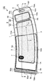
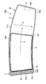
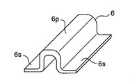
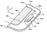
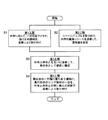
- FIG. 1 It is a top view which shows the blood pressure measurement cuff of one Embodiment of this invention as seen from the outer cloth side in the unfolded state. It is a figure which shows the cross section of the blood pressure measurement cuff of FIG. 1 when cut along the line II-II. It is a top view which shows the view from the inner cloth side of the blood pressure measurement cuff of FIG. It is an enlarged perspective view which shows the retaining member which constitutes the blood pressure measurement cuff independently. It is a perspective view which shows the vicinity of the region where the said retaining member of the said blood pressure measuring cuff is provided. It is a figure which shows the flow of the manufacturing method which manufactures the cuff for blood pressure measurement.
- FIG. 6A It is a top view which shows the outer cloth prepared for manufacturing the cuff for blood pressure measurement. It is a figure which shows the cross section (end face) at the time of cutting along the VIB-VIB line in FIG. 6A.
- Is. It is a figure which shows the cross section at the time of cutting along the line XB-XB in FIG. 10A.
- FIG. 12A It is a top view which shows the view from the surface side of the outer cloth for demonstrating the process of welding the retaining member to the outer cloth included in the 1st step in the manufacturing method of the blood pressure measurement cuff. .. It is a figure which shows the cross section at the time of cutting along the line XIIB-XIIB in FIG. 12A.
- the back surface of the inner cloth for explaining the step of attaching the nipple and the sheet forming the fluid bag to the back surface side of the inner cloth by welding, which is included in the second step.
- FIG. 13A It is a figure which shows the cross section at the time of cutting along the line XIIIB-XIIIB in FIG. 13A. It is a top view which shows the thing shown in FIG. 13A as seen from the surface side of the inner cloth.
- the back surface of the inner cloth for explaining the step of attaching the nipple and the sheet forming the fluid bag to the back surface side of the inner cloth by welding, which is included in the second step.
- FIG. 14A It is a figure which shows the cross section at the time of cutting along the XIVB-XIVB line in FIG. 14A. It is a top view which shows the thing shown in FIG.
- the back surface of the inner cloth for explaining the step of attaching the nipple and the sheet forming the fluid bag to the back surface side of the inner cloth by welding, which is included in the second step.
- FIG. 16A It is a top view which shows the view from the outer cloth side for demonstrating the step of welding the outer cloth and the inner cloth to each other included in the 3rd step in the manufacturing method of the blood pressure measurement cuff. It is a figure which shows the cross section at the time of cutting along the XVIB-XVIB line in FIG. 16A. It is a top view which shows the thing shown in FIG. 16A as seen from the inner cloth side. It is a top view which shows the view from the outer cloth side for demonstrating the step of welding the outer cloth and the inner cloth to each other included in the 3rd step in the manufacturing method of the blood pressure measurement cuff. It is a figure which shows the cross section at the time of cutting along the line XVIIB-XVIIB in FIG.
- FIG. 17A It is a top view which shows the thing shown in FIG. 17A as seen from the inner cloth side.
- FIG. 18A It is a top view which shows the thing shown in FIG. 18A as seen from the inner cloth side.
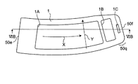
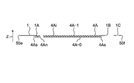
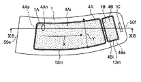
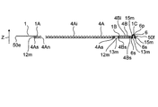
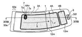
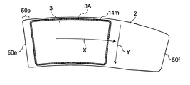
- FIG. 1 shows a planar configuration of the blood pressure measuring cuff 100 according to the present embodiment when viewed from the outer cloth 1 side.
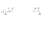
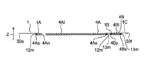
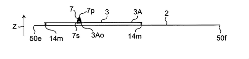
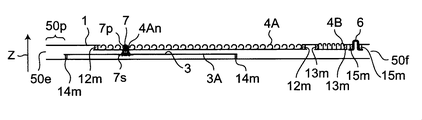
- FIG. 2 shows the cross-sectional configuration of the blood pressure measuring cuff 100 when FIG. 1 is cut along the line II-II.
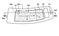
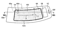
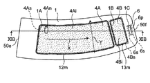
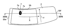
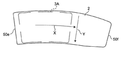
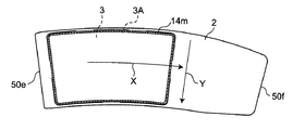
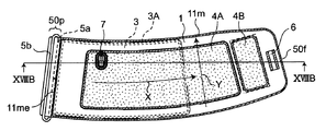
- FIG. 3 shows a planar configuration of the blood pressure measuring cuff 100 when viewed from the inner cloth 2 side.
- FIGS. 1, 2 and 3 show the overall configuration of the blood pressure measurement cuff 100 in the deployed state (that is, the state is not surrounded by the measurement site).
- the blood pressure measurement cuff 100 is a folded-back type cuff that surrounds and presses the measurement site.
- the blood pressure measurement cuff 100 surrounds the measurement site (for example, the upper left arm) along the circumferential direction.
- the circumferential direction of the measurement site corresponds to the "longitudinal direction X" of the blood pressure measurement cuff 100 (in other words, the band-shaped body 50 described later).
- the direction perpendicular to the longitudinal direction X is referred to as "width direction Y".
- the direction perpendicular to both the longitudinal direction X and the width direction Y is called the "thickness direction Z" (see FIG. 2).
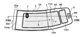
- the blood pressure measuring cuff 100 includes a strip 50, a fluid bag 3, a pair of hook-and-loop fasteners 4A and 4B as fixing members 4, a ring member 5, a retaining member 6, and a reinforcing layer 10 (see FIG. 2). There is.
- the strip 50 has an arc shape in the plan view of FIGS. 1 and 3, and extends along the longitudinal direction X.
- the strip 50 includes an outer cloth 1 and an inner cloth 2.
- the outer cloth 1 and the inner cloth 2 are welded to each other to form a bag-shaped strip 50.
- the strip 50 houses the fluid bag 3 (see FIG. 2).
- the outline of the fluid bag 3 is shown by a broken line.
- the outer cloth 1 constituting the strip 50 is a cloth located on the outer peripheral side when surrounding the part to be measured (for example, the upper left arm).
- the inner cloth 2 constituting the strip-shaped body 50 is a cloth located on the inner peripheral side when surrounding the portion to be measured.
- the "cloth” is not limited to the woven one, and may consist of one layer or a plurality of layers of resin.
- the inner cloth 2 When measuring blood pressure, the inner cloth 2 is in contact with the part to be measured.
- the outer cloth 1 faces the inner cloth 2 and does not come into contact with the measured portion when measuring blood pressure.
- the outer cloth 1 and the inner cloth 2 are welded along a circular line (which can also be grasped as a welded welding region) 11 m on the substantially peripheral edges of each other.
- the bag-shaped strip 50 is formed by the welding (the welding line 11 m) is shown by diagonal lines).
- the surface of the outer cloth 1 and the surface of the inner cloth 2 facing the outside of the strip 50 are the "surface" of the outer cloth 1 and the inner cloth 2 respectively. Called the "surface” of.
- the surface of the outer cloth 1 facing the inner cloth 2 is referred to as the "back surface” of the outer cloth 1.
- the surface of the inner cloth 2 facing the outer cloth 1 is referred to as the "back surface” of the inner cloth 2.
- the surface of the inner cloth 2 comes into contact with the measurement site.
- the inner cloth 2 is formed by laminating two layers of a polyester cloth and a polyurethane film that can be easily expanded and contracted.
- the polyester cloth constitutes the front surface of the inner cloth 2
- the polyurethane film constitutes the back surface of the inner cloth 2.
- the outer cloth 1 is formed by laminating three layers of a nylon cloth, a tarpaulin layer, and a polyurethane film that can be easily expanded and contracted.
- the nylon cloth constitutes the front surface of the outer cloth 1
- the polyurethane film constitutes the back surface of the outer cloth 1.
- the strip 50 has two ends (one end 50e and the other end 50f) in the longitudinal direction X.
- the other end 50f faces the one end 50e in the longitudinal direction X.
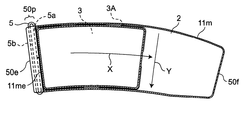
- one side 5a of the ring member 5 is attached to the region 50p of the strip 50 connected to one end 50e.
- One side 5a of the ring member 5 is arranged on the strip 50 along the width direction Y intersecting the longitudinal direction X.
- the one end 50e and the other end 50f each point to a true end (1 point) with respect to the longitudinal direction X.
- the ring member 5 is made of, for example, a metal material and has an oval shape (including two rod-shaped sides 5a and 5b and two arc-shaped connecting portions connecting the ends of the sides 5a and 5b). doing.
- one side 5a of the ring member 5 is arranged (sandwiched) between the outer cloth 1 and the inner cloth 2 in the region 50p of the strip-shaped body 50.
- the other side 5b is arranged outside the outer cloth 1. In this way, with one side 5a of the ring member 5 sandwiched between the outer cloth 1 and the inner cloth 2, the ring member 5 has the one side 5a with respect to the strip 50 as shown by an arrow Q. It is rotatable around the.
- the above-mentioned welding line 11m passes through a portion (8 to 13 mm) of the region 50p (8 to 13 mm) on the + X side (welding region 11me shown in FIG. 2) on the side of one end 50e of the strip 50. There is.
- a substantially rectangular end opening 1C is provided in a region 50q of the outer cloth 1 adjacent to the other end 50f in the longitudinal direction X, and projects from the end opening 1C.
- the retaining member 6 is arranged as described above.
- FIG. 4A shows the retaining member 6 by itself in an enlarged manner
- FIG. 4B shows the vicinity of the region 50q of the strip-shaped body 50 where the retaining member 6 is provided.
- the retaining member 6 is made of an integral material having flexibility (for example, an elastomer material), and has a protrusion 6p protruding outward in the thickness direction Z of the strip 50 through the end opening 1C. It includes flat plate-shaped support portions 6s and 6s connected to the base of the protrusion 6p.
- the cross section of the protrusion 6p of the retaining member 6 along the longitudinal direction X has an inverted U shape with a rounded tip in the thickness direction Z.
- the support portions 6s and 6s are welded and attached to the back surface of the outer cloth 1 along the linear lines 15 m and 15 m (see FIGS. 1 and 2).
- the X-direction dimension of the protrusion 6p is set to about 7.5 mm.
- the X-direction dimension of the entire retaining member 6 is set to about 15 mm.
- the Y-direction dimension of the protrusion 6p (and the support 6s) is set to about 35 mm.
- the Z-direction dimension (thickness) from the surface of the inner cloth 2 to the tip of the protrusion 6p is about 8 mm in this example, and is from the gap between the sides 5a and 5b of the ring member 5 (about 7 mm in this example). Is also set large.
- a portion (including the retaining member 6) connected to the other end 50f of the band-shaped body 50 is inserted through the ring member 5 and the band-shaped body 50 is inserted.
- the retaining member 6 prevents the other end 50f of the strip 50 from falling out of the ring member 5 when is formed into a substantially cylindrical shape (details will be described later).
- the first opening 1A is provided in the central region in the longitudinal direction X
- the second opening 1A is provided in the region between the first opening 1A and the end opening 1C.
- An opening 1B is provided.
- a loop-shaped surface fastener 4A and a hook-shaped surface fastener 4B are provided so as to occupy these openings 1A and 1B, respectively.
- the hook-and-loop fastener 4A includes a flat base material layer 4A-0 and a large number of loops 4A-1 erected on the base material layer 4A-0.
- the hook-and-loop fastener 4B includes a flat base material layer 4B-0 and a large number of hooks 4B-1 erected on the base material layer 4B-0.
- the peripheral portion 4As of the loop-shaped hook-and-loop fastener 4A is welded to the back surface around the first opening 1A of the outer cloth 1 along the annular line 12m. Further, the peripheral portion 4Bs of the hook-shaped surface fastener 4B is welded to the back surface around the second opening 1B of the outer cloth 1 along the annular line 13m.
- the main portions (the portions surrounded by the peripheral portions 4As and 4Bs) 4Ai and 4Bi of the pair of hook-and-loop fasteners 4A and 4B are exposed to the surface side of the outer cloth 1 through the first opening 1A and the second opening 1B, respectively. It is in a state.
- loops and hooks are omitted for flattening, respectively.
- the hook-shaped surface fastener 4B is connected to the other end 50f of the strip-shaped body 50, folded back through the ring member 5, and is detachably engaged with the loop-shaped surface fastener 4A occupying the opposite portion of the outer cloth 1.
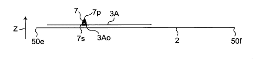
- the fluid bag 3 has an inner cloth 2 and a sheet (made of a stretchable polyurethane film) 3A facing the back surface of the inner cloth 2 in an annular line. It is configured by welding to each other along 14 m.
- a nipple 7 is attached to a part of the sheet 3A.
- the outer cloth 1 (more specifically, the main portion 4Ai of the hook-and-loop fastener 4A provided along the outer cloth 1) has an opening 4An for exposing the nipple 7 (for example, FIGS. 7A and 7B described later). (Shown inside) is provided.
- the nipple 7 includes a cylindrical portion 7p protruding to the outside of the strip 50 through the opening 4An, and a flange-shaped support portion 7s connected to the base of the cylindrical portion 7p. The support portion 7s is welded to the sheet 3A, whereby the nipple 7 is supported by the sheet 3A.
- a through hole 3Ao is provided in a portion of the sheet 3A where the nipple 7 is provided. This allows the flow of fluid through the sheet 3A (and the main part 4Ai of the hook-and-loop fastener 4A). That is, the fluid can be supplied to the fluid bag 3 from the outside of the strip 50 via the nipple 7. On the contrary, the fluid can be discharged from the fluid bag 3 to the outside of the strip 50 via the nipple 7.
- the region corresponding between the one end 50e and one side 5a of the ring member 5 is the outer cloth 1 and the inner cloth 2.
- a reinforcing layer 10 is sandwiched between them, and the welding area is 16 m.
- the reinforcing layer 10 means a layer in which the rigidity of this layer is higher than the rigidity of the inner cloth 2 and the hardness of the outer cloth 1. Rigidity and softness can be measured, for example, using the 45 ° cantilever method.
- the reinforcing layer 10 is made of the same material as the loop-shaped surface fastener 4A in order to standardize the members, and is erected on the flat base material layer 10A-0 and the base material layer 10A-0. It contains a large number of loops 10A-1. As a result, the material can be standardized between the surface fastener 4A and the reinforcing layer 10, and the manufacturing cost can be reduced. Further, when the blood pressure measurement cuff 100 is attached to the measurement site, the region 50p adjacent to one end 50e of the band 50 is folded toward the measurement site side, that is, the skin side due to the presence of the reinforcing layer 10. It can be prevented from bending and getting caught.
- a step (first step) for the outer cloth 1 is carried out.
- the outer cloth 1 is cut into the shape of the outer cloth 1 previously shown in FIG. 1, and in particular, the first opening 1A, the second opening 1B, and the end opening 1C. Is already provided.
- FIG. 6A shows the outer cloth 1 viewed from the front surface side (the same applies to FIGS. 7A, 8A, ..., 12A described later).
- FIG. 6B shows a cross section (end face) when cut along the VIB-VIB line in FIG. 6A (FIGS. 7A, 8A, ..., FIG. 12A described later, FIGS. 7B, 8B, respectively. ..., The same applies in FIG. 12B.).
- step S1 first step of FIG. 5, first, as shown in FIGS. 7A and 7B, the loop-shaped hook-and-loop fastener 4A is aligned with the first opening 1A of the outer cloth 1. Specifically, the peripheral edge portion 4As of the hook-and-loop fastener 4A is overlapped on the back surface around the first opening 1A of the outer cloth 1 in the thickness direction Z (from the ⁇ Z direction), and the main portion 4Ai of the hook-and-loop fastener 4A is the first. The outer cloth 1 is exposed to the surface side through the opening 1A. In this state, as shown in FIGS.
- the peripheral portion 4As of the hook-and-loop fastener 4A is formed into an annular line 12m on the back surface around the first opening 1A of the outer cloth 1. Weld along. As a result, the hook-and-loop fastener 4A is attached to the outer cloth 1. It is assumed that the hook-and-loop fastener 4A is provided with an opening 4An in advance for exposing the nipple 7. Subsequently, as shown in FIGS. 9A and 9B, the hook-shaped surface fastener 4B is aligned with the second opening 1B of the outer cloth 1.
- the peripheral edge portion 4Bs of the hook-and-loop fastener 4B is overlapped on the back surface around the second opening 1B of the outer cloth 1 in the thickness direction Z (from the ⁇ Z direction), and the main portion 4Bi of the hook-and-loop fastener 4B is the first. 2
- the outer cloth 1 is exposed to the surface side through the opening 1B.
- the peripheral edge portion 4Bs of the hook-and-loop fastener 4B is formed on the back surface around the second opening 1B of the outer cloth 1 to an annular line 13 m. Weld along.
- the hook-and-loop fastener 4B is attached to the outer cloth 1.
- the retaining member 6 is aligned with the end opening 1C of the outer cloth 1.
- the support portions 6s and 6s of the retaining member 6 are superposed on the back surfaces of the end opening 1C of the outer cloth 1 on both sides in the X direction in the thickness direction Z (from the ⁇ Z direction) to prevent the retaining member 6 from coming off.
- the protruding portion 6p of the above is made to protrude to the outside of the strip 50 in the thickness direction Z through the end opening 1C. In this state, as shown in FIGS.
- the support portions 6s and 6s of the retaining member 6 are attached to the back surfaces of the end opening 1C of the outer cloth 1 on both sides in the X direction by using a welding tool (not shown). Welding is performed along straight lines 15 m and 15 m. As a result, the retaining member 6 is attached to the region 50q adjacent to the other end 50f of the outer cloth 1.
- the attachment of the pair of hook-and-loop fasteners 4A and 4B is simplified by processing the outer cloth 1 in the thickness direction Z (suitable for automation). Further, since the pair of hook-and-loop fasteners 4A and 4B are planar, the peripheral portions 4As and 4Bs of the pair of hook-and-loop fasteners 4A and 4B are formed on the back surface around the first opening 1A and the second opening 1B of the outer cloth 1, respectively. When stacked on the back surface around the cloth 1, the outer cloth 1 has a gentle inclination with respect to the thickness direction Z. Therefore, the peripheral portions 4As and 4Bs of the pair of hook-and-loop fasteners 4A and 4B are easily welded to the back surface around the first opening 1A and the back surface around the second opening 1B of the outer cloth 1, respectively.
- the attachment of the retaining member 6 is simplified by processing the outer cloth 1 in the thickness direction Z (suitable for automation). Further, since the support portions 6s and 6s of the retaining member 6 are flat plates, when the support portions 6s and 6s of the retaining member 6 are overlapped on the back surface around the end opening 1C of the outer cloth 1, the outside The inclination of the cloth 1 with respect to the thickness direction Z becomes gentle. Therefore, the support portions 6s and 6s of the retaining member 6 are easily welded to the back surface around the end opening 1C of the outer cloth 1. As a result, the support portions 6s and 6s of the retaining member 6 are easily attached to the back surface around the end opening 1C of the outer cloth 1.
- the loop-shaped surface fastener 4A, the hook-shaped surface fastener 4B, and the retaining member 6 were attached to the outer cloth 1 in this order, but the present invention is not limited to this.
- the attachment (welding) of the three members 4A, 4B, 6 may be performed in any order, or may be performed in parallel with each other.
- step S2 of FIG. 5 a step (second step) for the inner cloth 2 is carried out.
- the inner cloth 2 and the sheet 3A are cut into the shapes of the inner cloth 2 and the sheet 3A shown in FIG. 3, respectively, as shown in FIGS. 13A, 13B, and 13C.
- FIG. 13A shows the inner cloth 2 viewed from the back surface side (the same applies to FIGS. 14A and 15A described later).
- FIG. 13B shows a cross section (end face) when cut along the line XIIIB-XIIIB in FIG. 13A (the same applies to FIGS. 14A and 15A described later, respectively).
- FIG. 13C shows the inner cloth 2 viewed from the surface side (the same applies to FIGS. 14C and 15C described later).
- step S2 (second step) of FIG. 5, first, as shown in FIGS. 13A and 13B, the nipple 7 is aligned with respect to the sheet 3A. Specifically, in this example, the flange-shaped support portion 7s of the nipple 7 is provided on the surface (the surface closer to the inner cloth 2 after assembly) around the through hole 3Ao provided in advance in the sheet 3A. The nipple 7 is overlapped in the thickness direction Z (from the ⁇ Z direction) so that the cylindrical portion 7p of the nipple 7 protrudes in the thickness direction Z through the through hole 3Ao. In this state, as shown in FIGS.
- the flange-shaped support portion 7s of the nipple 7 is welded to the surface around the through hole 3Ao of the sheet 3A by using a welding tool (not shown).
- the nipple 7 is attached to the seat 3A.
- the sheet 3A is aligned with the inner cloth 2.
- the sheet 3A faces the region of the back surface of the inner cloth 2, which is more than half of the side close to one end 50e in the longitudinal direction X and occupies most of the width direction Y. Align.
- the sheet 3A is welded to the back surface of the inner cloth 2 along the annular line 14m by using a welding tool (not shown).
- the fluid bag 3 is formed.
- step S2 (second step) was performed after step S1 (first step), but the present invention is not limited to this.
- Step S1 may be performed after step S2, or step S1 and step S2 may be performed in parallel with each other.
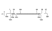
- step S3 of FIG. 5 the strip-shaped body 50 is formed by the outer cloth 1 and the inner cloth 2 (third step).
- FIGS. 16A, 16B, and 16C the outer cloth 1 that has undergone step S1 and the inner cloth 2 that has undergone step S2 are aligned so as to face each other in the thickness direction Z.
- FIG. 16A shows a view of the aligned pair of the outer cloth 1 and the inner cloth 2 as viewed from the outer cloth 1 side (the same applies to FIGS. 17A and 18A described later).
- FIG. 16B shows a cross section when cut along the line XVIB-XVIB in FIG. 16A (the same applies to FIGS. 17A and 18A described later, respectively). Further, FIG.
- FIGS. 16C shows the aligned pair of the outer cloth 1 and the inner cloth 2 as viewed from the inner cloth 2 side (the same applies to FIGS. 17C and 18C described later).
- the cylindrical portion 7p of the nipple 7 protrudes outward in the thickness direction Z through the opening 4An of the hook-and-loop fastener 4A.
- FIGS. 17A, 17B, and 17C with the fluid bag 3 housed, using a welding tool (not shown), the outer cloth 1 and the inner cloth 1 and the inner cloth 1 and the inner cloth 1 and the inner cloth 1 are left adjacent to one end 50e.
- the substantially peripheral edges of the cloths 2 are welded along the annular line 11 m.
- the band-shaped body 50 is formed in a bag shape.
- the welding line 11m passes through a portion (welding region 11me) on the side of one end 50e of the strip 50 that is on the + X side by the amount of the region 50p.
- the nipple 7 (cylindrical portion 7p) can be passed through the opening 4An simply by overlapping the outer cloth 1 and the inner cloth 2 in the thickness direction Z.
- the process of integrating the outer cloth 1 and the inner cloth 2 becomes a process in the thickness direction Z, which is easy (suitable for automation).
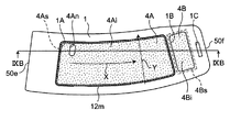
- step S4 of FIG. 5 the oval ring member 5 is attached to the region 50p adjacent to one end 50e of the strip 50 (fourth step).
- the outer cloth 1 and the inner cloth 2 are formed in the region 50p connected to one end 50e of the strip 50 along the welding region 11me.
- One side 5a of the ring member 5 is arranged between them.
- the other side 5b of the ring member 5 is arranged on the outside (front surface side) of the outer cloth 1.
- the reinforcing layer 10 (the same member as the loop-shaped surface fastener 4A) is formed in the region 16 m between the outer cloth 1 and the inner cloth 2 between one end 50e and one side 5a of the ring member 5. ) Is placed. In this state, as shown in FIGS.
- the outer cloth 1, the inner cloth 2, and the reinforcing layer 10 are attached to one end 50e and one side 5a of the ring member 5.
- Welding is performed collectively in the corresponding area (welding area) 16 m between the two.
- one side 5a of the oval ring member 5 is placed between the outer cloth 1 and the inner cloth 2 in the region 50p adjacent to one end 50e of the strip 50 in the direction intersecting the strip 50. Attach it while sandwiching it between.
- the ring member 5 becomes rotatable around one side 5a with respect to the strip 50.
- the process of arranging the ring member 5 and the reinforcing layer 10 in the region 50p adjacent to one end 50e of the strip 50 in the above-mentioned fourth step is a process involving movement in the plane direction with respect to the strip 50.
- one end 50e of the strip 50 is an open end (the outer cloth 1 and the inner cloth 2 are welded)
- the difficulty of processing is relatively small.
- the process of collectively welding the outer cloth 1, the inner cloth 2, and the reinforcing layer 10 is a process in the thickness direction Z, and thus can be easily performed.
- the reinforcing layer 10 is attached to the band-shaped body 50 at the same time as the ring member 5. Therefore, the number of steps is not excessively increased to provide the reinforcing layer 10.
- the above-mentioned folded-back type blood pressure measuring cuff 100 can be easily assembled by welding.
- this method for manufacturing the blood pressure measuring cuff 100 is suitable for automation because it mainly includes the treatment of the band-shaped body 50 (outer cloth 1, inner cloth 2) in the thickness direction Z.
- the above-mentioned folded-back type blood pressure measuring cuff 100 has the following effects at the stage of use.
- the outer cloth 1 is on the outer peripheral side and the inner cloth 2 is on the inner peripheral side as shown by the arrow A1 in FIG. 19A.
- a portion (including the retaining member 6) connected to the other end 50f of the strip-shaped body 50 is inserted into the ring member 5.
- the strip 50 becomes substantially cylindrical.
- the cross section of the protrusion 6p of the retaining member 6 along the longitudinal direction X has an inverted U shape with a rounded tip in the thickness direction Z.
- the protrusion 6p of the retaining member 6 is likely to be dented. Therefore, when the strip-shaped body 50 is made substantially cylindrical for attachment to the measurement site, a portion (including the retaining member 6) connected to the other end 50f of the strip-shaped body 50 is easily inserted into the ring member 5.
- the retaining member 6 prevents the other end 50f of the strip 50 from falling out of the ring member 5.
- the thickness from the surface of the inner cloth 2 to the tip of the protrusion 6p (about 8 mm in this example) is the gap between the sides 5a and 5b of the ring member 5 (this example). This is because it is set to be larger than about 7 mm).
- the upper left arm 90 is passed through the cylindrical strip 50, and the portion connected to the other end 50f of the strip 50 is oriented away from the upper left arm to the left side of the body. In addition, it is pulled once by the right hand.
- the reinforcing layer 10 (see FIG. 2) is provided in the region 50p adjacent to one end 50e of the strip 50, the region 50p adjacent to one end 50e of the strip 50 is on the side to be measured. That is, it can be prevented from being bent and caught on the skin side (upward in FIG. 19B).
- the portion connected to the other end 50f of the strip 50 is folded back.
- the hook-shaped hook-and-loop fastener 4B near the other end 50f of the strip-shaped body 50 is engaged with the loop-shaped hook-and-loop fastener 4B provided on the surface of the facing outer cloth 1.
- the portion of the strip 50 that is connected to the other end 50f and folded back through the ring member 5 is fixed to the opposite portion of the outer cloth 1 (mounting completed).
- a fluid typically, air
- the fluid bag 3 is supplied to the fluid bag 3 from the outside of the band 50 through the nipple 7, and the upper left arm 90 is compressed.
- blood pressure is measured, for example, by the oscillometric method.
- the retaining member 6 is attached to the strip-shaped body 50 by welding the supporting portions 6s and 6s of the retaining member 6 to the back surface around the end opening 1C of the outer cloth 1. It is not limited to this.
- the retaining member 6 may be attached to the region 50q of the strip-shaped body 50 adjacent to the other end 50f in a state of protruding outward in the thickness direction Z.
- the support portions 6s and 6s of the retaining member 6 may be welded to the surface of the outer cloth 1 from the + Z direction and attached. In that case, the end opening 1C of the outer cloth 1 becomes unnecessary.
- an end opening 1C is provided in a region 50q of the strip 50 adjacent to the other end 50f so as to penetrate the outer cloth 1 and the inner cloth 2, and the protrusion 6p of the retaining member 6 is inside. It may be attached in a state of protruding outward in the thickness direction Z from the cloth 2 side to the outer cloth 1 side through the end opening 1C. In that case, the support portions 6s and 6s of the retaining member 6 are collectively welded around the end opening 1C of the outer cloth 1 and the inner cloth 2 from the ⁇ Z direction.
- the retaining member 6 is not limited to the type (see FIG. 4A) in which the cross section of the protrusion 6p described above along the longitudinal direction X is inverted U-shaped.
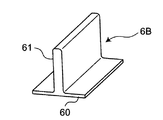
- the retaining member (indicated by reference numeral 6B) is a type having a flat plate-shaped support portion 60 and a flat plate-shaped protrusion 61 erected in the center of the support portion 60. It may be.
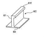
- the retaining member (indicated by reference numeral 6C) has a flat plate-shaped support portion 60 and a flat plate-shaped protrusion 61 erected in the center of the support portion 60. Further, the tip of the protrusion 61 may be bent in a direction parallel to the support 60.
- the reinforcing layer 10 in the region 50p adjacent to one end 50e may be omitted. That is, only the outer cloth 1 and the inner cloth 2 are welded in the region (welding region) 16 m corresponding to the one end 50e and the one side 5a of the ring member 5, and the one side 5a of the ring member 5 is welded to the strip 50. May be attached. As a result, the manufacturing cost can be reduced.
- the measurement site may be an upper limb or a lower limb other than the upper left arm.
Landscapes
- Health & Medical Sciences (AREA)
- Life Sciences & Earth Sciences (AREA)
- Vascular Medicine (AREA)
- Cardiology (AREA)
- Engineering & Computer Science (AREA)
- Physiology (AREA)
- Molecular Biology (AREA)
- Ophthalmology & Optometry (AREA)
- Biophysics (AREA)
- Pathology (AREA)
- Dentistry (AREA)
- Biomedical Technology (AREA)
- Heart & Thoracic Surgery (AREA)
- Medical Informatics (AREA)
- Physics & Mathematics (AREA)
- Surgery (AREA)
- Animal Behavior & Ethology (AREA)
- General Health & Medical Sciences (AREA)
- Public Health (AREA)
- Veterinary Medicine (AREA)
- Mechanical Engineering (AREA)
- Measuring Pulse, Heart Rate, Blood Pressure Or Blood Flow (AREA)
Priority Applications (3)
| Application Number | Priority Date | Filing Date | Title |
|---|---|---|---|
| CN202080051546.3A CN114173648B (zh) | 2019-07-18 | 2020-07-09 | 血压测定用袖带及其制造方法 |
| DE112020003456.9T DE112020003456T5 (de) | 2019-07-18 | 2020-07-09 | Blutdruckmessmanschette und verfahren zum herstellen derselben |
| US17/573,749 US12329502B2 (en) | 2019-07-18 | 2022-01-12 | Blood pressure measurement cuff and method for manufacturing same |
Applications Claiming Priority (2)
| Application Number | Priority Date | Filing Date | Title |
|---|---|---|---|
| JP2019-132816 | 2019-07-18 | ||
| JP2019132816A JP7279557B2 (ja) | 2019-07-18 | 2019-07-18 | 血圧測定用カフおよびその製造方法 |
Related Child Applications (1)
| Application Number | Title | Priority Date | Filing Date |
|---|---|---|---|
| US17/573,749 Continuation US12329502B2 (en) | 2019-07-18 | 2022-01-12 | Blood pressure measurement cuff and method for manufacturing same |
Publications (1)
| Publication Number | Publication Date |
|---|---|
| WO2021010266A1 true WO2021010266A1 (ja) | 2021-01-21 |
Family
ID=74210765
Family Applications (1)
| Application Number | Title | Priority Date | Filing Date |
|---|---|---|---|
| PCT/JP2020/026780 Ceased WO2021010266A1 (ja) | 2019-07-18 | 2020-07-09 | 血圧測定用カフおよびその製造方法 |
Country Status (5)
| Country | Link |
|---|---|
| US (1) | US12329502B2 (enExample) |
| JP (1) | JP7279557B2 (enExample) |
| CN (1) | CN114173648B (enExample) |
| DE (1) | DE112020003456T5 (enExample) |
| WO (1) | WO2021010266A1 (enExample) |
Families Citing this family (1)
| Publication number | Priority date | Publication date | Assignee | Title |
|---|---|---|---|---|
| JP7468223B2 (ja) * | 2020-07-27 | 2024-04-16 | オムロンヘルスケア株式会社 | 血圧測定用カフ |
Citations (4)
| Publication number | Priority date | Publication date | Assignee | Title |
|---|---|---|---|---|
| JPS55134806U (enExample) * | 1979-03-15 | 1980-09-25 | ||
| JPS59183206U (ja) * | 1983-05-21 | 1984-12-06 | モリト株式会社 | 締付用バンド |
| JPH0535103U (ja) * | 1991-10-22 | 1993-05-14 | オムロン株式会社 | 血圧計のカフ帯 |
| JP2010252836A (ja) * | 2009-04-21 | 2010-11-11 | Citizen Systems Japan Co Ltd | 生体圧迫装置及び血圧測定装置 |
Family Cites Families (7)
| Publication number | Priority date | Publication date | Assignee | Title |
|---|---|---|---|---|
| JP2000237150A (ja) * | 1999-02-19 | 2000-09-05 | Omron Corp | 血圧計用カフ |
| US8652057B2 (en) * | 2009-05-19 | 2014-02-18 | Welch Allyn, Inc. | Recyclable or biodegradable blood pressure cuff |
| JP5236046B2 (ja) * | 2011-06-09 | 2013-07-17 | シチズン・システムズ株式会社 | 生体圧迫装置 |
| JP5749600B2 (ja) * | 2011-08-11 | 2015-07-15 | 株式会社エー・アンド・デイ | 血圧計用カフ |
| TW201325549A (zh) * | 2011-12-23 | 2013-07-01 | Ind Tech Res Inst | 壓脈袋裝置 |
| JP6051964B2 (ja) * | 2013-03-07 | 2016-12-27 | オムロンヘルスケア株式会社 | 血圧測定用カフ、および、血圧測定用カフの製造方法 |
| CN105286834B (zh) * | 2015-11-30 | 2018-06-29 | 北京东方泰华科技发展有限公司 | 一种血压袖带及动态血压计产品 |
-
2019
- 2019-07-18 JP JP2019132816A patent/JP7279557B2/ja active Active
-
2020
- 2020-07-09 WO PCT/JP2020/026780 patent/WO2021010266A1/ja not_active Ceased
- 2020-07-09 DE DE112020003456.9T patent/DE112020003456T5/de active Pending
- 2020-07-09 CN CN202080051546.3A patent/CN114173648B/zh active Active
-
2022
- 2022-01-12 US US17/573,749 patent/US12329502B2/en active Active
Patent Citations (4)
| Publication number | Priority date | Publication date | Assignee | Title |
|---|---|---|---|---|
| JPS55134806U (enExample) * | 1979-03-15 | 1980-09-25 | ||
| JPS59183206U (ja) * | 1983-05-21 | 1984-12-06 | モリト株式会社 | 締付用バンド |
| JPH0535103U (ja) * | 1991-10-22 | 1993-05-14 | オムロン株式会社 | 血圧計のカフ帯 |
| JP2010252836A (ja) * | 2009-04-21 | 2010-11-11 | Citizen Systems Japan Co Ltd | 生体圧迫装置及び血圧測定装置 |
Also Published As
| Publication number | Publication date |
|---|---|
| JP7279557B2 (ja) | 2023-05-23 |
| DE112020003456T5 (de) | 2022-03-31 |
| JP2021016476A (ja) | 2021-02-15 |
| CN114173648B (zh) | 2024-04-26 |
| US20220133160A1 (en) | 2022-05-05 |
| US12329502B2 (en) | 2025-06-17 |
| CN114173648A (zh) | 2022-03-11 |
Similar Documents
| Publication | Publication Date | Title |
|---|---|---|
| KR20140033032A (ko) | 마스크의 제조 방법, 마스크 | |
| KR20140034170A (ko) | 마스크 | |
| JP6051964B2 (ja) | 血圧測定用カフ、および、血圧測定用カフの製造方法 | |
| WO2012137942A1 (ja) | マスク | |
| JP2014171606A5 (enExample) | ||
| WO2021010266A1 (ja) | 血圧測定用カフおよびその製造方法 | |
| JP2021016476A5 (enExample) | ||
| CN1937986A (zh) | 穿着物品 | |
| JP5407446B2 (ja) | 男性用尿パッド | |
| JP3488821B2 (ja) | マスク | |
| JP4907793B2 (ja) | ペット用オムツ | |
| JP6309665B1 (ja) | マスク | |
| JP2011115443A (ja) | 車両用シート | |
| CN109475103A (zh) | 带状体 | |
| JP2021003367A (ja) | 血圧測定用カフ | |
| JP2022023650A (ja) | 血圧測定用カフ | |
| JP4949985B2 (ja) | 吸収性物品 | |
| JP2019165878A (ja) | 吸収性物品 | |
| JP7669717B2 (ja) | 血圧測定用カフ | |
| JP7468223B2 (ja) | 血圧測定用カフ | |
| JP2012254113A (ja) | 陰茎保持具 | |
| JP7173829B2 (ja) | パンツ型吸収性物品 | |
| JP2021094070A (ja) | カバー部材とそれを備えた加圧ベルト | |
| JP2024176733A (ja) | マスクおよびマスクの製造装置 | |
| WO2023010130A1 (en) | Face mask strap retention method and system |
Legal Events
| Date | Code | Title | Description |
|---|---|---|---|
| 121 | Ep: the epo has been informed by wipo that ep was designated in this application |
Ref document number: 20838875 Country of ref document: EP Kind code of ref document: A1 |
|
| 122 | Ep: pct application non-entry in european phase |
Ref document number: 20838875 Country of ref document: EP Kind code of ref document: A1 |