WO2021010049A1 - Dispositif de stockage d'énergie - Google Patents
Dispositif de stockage d'énergie Download PDFInfo
- Publication number
- WO2021010049A1 WO2021010049A1 PCT/JP2020/022212 JP2020022212W WO2021010049A1 WO 2021010049 A1 WO2021010049 A1 WO 2021010049A1 JP 2020022212 W JP2020022212 W JP 2020022212W WO 2021010049 A1 WO2021010049 A1 WO 2021010049A1
- Authority
- WO
- WIPO (PCT)
- Prior art keywords
- power storage
- reinforcing member
- storage element
- element unit
- exterior body
- Prior art date
Links
- 238000003860 storage Methods 0.000 title claims abstract description 269
- 230000003014 reinforcing effect Effects 0.000 claims description 201
- 229910052751 metal Inorganic materials 0.000 claims description 15
- 239000002184 metal Substances 0.000 claims description 15
- 239000011347 resin Substances 0.000 claims description 6
- 229920005989 resin Polymers 0.000 claims description 6
- 230000002787 reinforcement Effects 0.000 abstract description 12
- 230000004048 modification Effects 0.000 description 28
- 238000012986 modification Methods 0.000 description 28
- 230000002093 peripheral effect Effects 0.000 description 10
- XEEYBQQBJWHFJM-UHFFFAOYSA-N Iron Chemical compound [Fe] XEEYBQQBJWHFJM-UHFFFAOYSA-N 0.000 description 8
- 230000005611 electricity Effects 0.000 description 8
- 239000000463 material Substances 0.000 description 8
- 238000009434 installation Methods 0.000 description 6
- 238000004519 manufacturing process Methods 0.000 description 5
- -1 polypropylene Polymers 0.000 description 5
- 230000036544 posture Effects 0.000 description 5
- 238000010586 diagram Methods 0.000 description 4
- 229910052742 iron Inorganic materials 0.000 description 4
- 239000011255 nonaqueous electrolyte Substances 0.000 description 4
- 229920001955 polyphenylene ether Polymers 0.000 description 4
- 238000000638 solvent extraction Methods 0.000 description 4
- 239000000853 adhesive Substances 0.000 description 3
- 230000001070 adhesive effect Effects 0.000 description 3
- 229910052782 aluminium Inorganic materials 0.000 description 3
- XAGFODPZIPBFFR-UHFFFAOYSA-N aluminium Chemical compound [Al] XAGFODPZIPBFFR-UHFFFAOYSA-N 0.000 description 3
- 238000000465 moulding Methods 0.000 description 3
- 229920013636 polyphenyl ether polymer Polymers 0.000 description 3
- 229910000838 Al alloy Inorganic materials 0.000 description 2
- RTZKZFJDLAIYFH-UHFFFAOYSA-N Diethyl ether Chemical compound CCOCC RTZKZFJDLAIYFH-UHFFFAOYSA-N 0.000 description 2
- HBBGRARXTFLTSG-UHFFFAOYSA-N Lithium ion Chemical compound [Li+] HBBGRARXTFLTSG-UHFFFAOYSA-N 0.000 description 2
- 239000004696 Poly ether ether ketone Substances 0.000 description 2
- 239000004698 Polyethylene Substances 0.000 description 2
- 239000004734 Polyphenylene sulfide Substances 0.000 description 2
- 239000004743 Polypropylene Substances 0.000 description 2
- 230000014509 gene expression Effects 0.000 description 2
- 229910001416 lithium ion Inorganic materials 0.000 description 2
- 238000000034 method Methods 0.000 description 2
- 230000000149 penetrating effect Effects 0.000 description 2
- 229920001707 polybutylene terephthalate Polymers 0.000 description 2
- 229920002530 polyetherether ketone Polymers 0.000 description 2
- 229920000573 polyethylene Polymers 0.000 description 2
- 229920000139 polyethylene terephthalate Polymers 0.000 description 2
- 239000005020 polyethylene terephthalate Substances 0.000 description 2
- 229920000069 polyphenylene sulfide Polymers 0.000 description 2
- 229920001155 polypropylene Polymers 0.000 description 2
- 229920001343 polytetrafluoroethylene Polymers 0.000 description 2
- 239000004810 polytetrafluoroethylene Substances 0.000 description 2
- 230000035939 shock Effects 0.000 description 2
- 238000003466 welding Methods 0.000 description 2
- RYGMFSIKBFXOCR-UHFFFAOYSA-N Copper Chemical compound [Cu] RYGMFSIKBFXOCR-UHFFFAOYSA-N 0.000 description 1
- 229910000881 Cu alloy Inorganic materials 0.000 description 1
- 229920012266 Poly(ether sulfone) PES Polymers 0.000 description 1
- 239000004793 Polystyrene Substances 0.000 description 1
- 238000010521 absorption reaction Methods 0.000 description 1
- 229920000122 acrylonitrile butadiene styrene Polymers 0.000 description 1
- 238000005452 bending Methods 0.000 description 1
- 230000005540 biological transmission Effects 0.000 description 1
- 239000003990 capacitor Substances 0.000 description 1
- 239000002131 composite material Substances 0.000 description 1
- 238000010276 construction Methods 0.000 description 1
- 229910052802 copper Inorganic materials 0.000 description 1
- 239000010949 copper Substances 0.000 description 1
- 238000007599 discharging Methods 0.000 description 1
- 230000000694 effects Effects 0.000 description 1
- 239000008151 electrolyte solution Substances 0.000 description 1
- 230000002708 enhancing effect Effects 0.000 description 1
- 239000012530 fluid Substances 0.000 description 1
- 230000017525 heat dissipation Effects 0.000 description 1
- 230000000116 mitigating effect Effects 0.000 description 1
- 239000004417 polycarbonate Substances 0.000 description 1
- 229920000515 polycarbonate Polymers 0.000 description 1
- 238000010248 power generation Methods 0.000 description 1
- 239000007784 solid electrolyte Substances 0.000 description 1
- 125000006850 spacer group Chemical group 0.000 description 1
- 239000010935 stainless steel Substances 0.000 description 1
- 229910001220 stainless steel Inorganic materials 0.000 description 1
- BFKJFAAPBSQJPD-UHFFFAOYSA-N tetrafluoroethene Chemical group FC(F)=C(F)F BFKJFAAPBSQJPD-UHFFFAOYSA-N 0.000 description 1
- 239000013585 weight reducing agent Substances 0.000 description 1
Images


Classifications
-
- H—ELECTRICITY
- H01—ELECTRIC ELEMENTS
- H01G—CAPACITORS; CAPACITORS, RECTIFIERS, DETECTORS, SWITCHING DEVICES, LIGHT-SENSITIVE OR TEMPERATURE-SENSITIVE DEVICES OF THE ELECTROLYTIC TYPE
- H01G11/00—Hybrid capacitors, i.e. capacitors having different positive and negative electrodes; Electric double-layer [EDL] capacitors; Processes for the manufacture thereof or of parts thereof
- H01G11/10—Multiple hybrid or EDL capacitors, e.g. arrays or modules
- H01G11/12—Stacked hybrid or EDL capacitors
-
- H—ELECTRICITY
- H01—ELECTRIC ELEMENTS
- H01G—CAPACITORS; CAPACITORS, RECTIFIERS, DETECTORS, SWITCHING DEVICES, LIGHT-SENSITIVE OR TEMPERATURE-SENSITIVE DEVICES OF THE ELECTROLYTIC TYPE
- H01G11/00—Hybrid capacitors, i.e. capacitors having different positive and negative electrodes; Electric double-layer [EDL] capacitors; Processes for the manufacture thereof or of parts thereof
- H01G11/78—Cases; Housings; Encapsulations; Mountings
Definitions
- the present invention relates to a power storage device including a power storage element unit composed of a plurality of power storage elements.
- Patent Document 1 discloses a power storage device module including a holder having an insulating property that integrates two or more power storage devices. Patent Document 1 describes that, by providing a holder, the power storage device module has a shape that is easy to handle as a whole and has improved mechanical or structural strength.
- the present invention has been made by the inventor of the present application paying new attention to the above problems, and an object of the present invention is to provide a power storage device provided with a plurality of power storage elements and having improved safety. To do.
- the power storage device accommodates a power storage element unit composed of a plurality of power storage elements arranged in the first direction, and the power storage element unit inside, and the power storage element unit is electrically charged.
- the reinforcement is provided with an exterior body having an external electrode terminal connected to the outer surface, and a reinforcing member arranged along a wall portion partitioning the inside and the outside of the exterior body and fixed to the exterior body.
- the member is composed of a plate-shaped reinforcing main body portion formed in a size covering the power storage element unit and the power storage element unit. Also includes a protruding portion protruding outward.
- the power storage device accommodates a power storage element unit composed of a plurality of power storage elements arranged in the first direction, and the power storage element unit inside, and the power storage element unit is electrically charged.
- the reinforcement is provided with an exterior body having an external electrode terminal connected to the outer surface, and a reinforcing member arranged along a wall portion partitioning the inside and the outside of the exterior body and fixed to the exterior body.
- the member is a protruding portion that protrudes outward from the power storage element unit when viewed from the second direction, which is the arrangement direction of the wall portion and the reinforcing member, and is another wall portion adjacent to the wall portion. It may include protrusions arranged along the outer surface of the.
- FIG. 1 is a perspective view showing the appearance of the power storage device according to the embodiment.
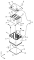
- FIG. 2 is an exploded perspective view showing each component when the power storage device according to the embodiment is disassembled.
- FIG. 3 is a perspective view showing the inside of the exterior body according to the embodiment.
- FIG. 4 is a perspective view of the power storage device according to the embodiment when viewed from diagonally below.
- FIG. 5 is a bottom view showing the relationship between the positions and sizes of the reinforcing member and the power storage element unit according to the embodiment.
- FIG. 6 is a cross-sectional view of a fixed portion of the reinforcing member in the exterior body according to the embodiment.
- FIG. 7 is a perspective view showing the configuration of the power storage device according to the first modification of the embodiment.
- FIG. 1 is a perspective view showing the appearance of the power storage device according to the embodiment.
- FIG. 2 is an exploded perspective view showing each component when the power storage device according to the embodiment is disassembled.
- FIG. 3 is a
- FIG. 8 is a diagram showing a cross-sectional shape of the reinforcing member according to the first modification of the embodiment.
- FIG. 9 is a perspective view showing the configuration of the power storage device according to the second modification of the embodiment.
- FIG. 10 is a diagram showing a cross-sectional shape of the reinforcing member according to the second modification of the embodiment.
- the power storage device accommodates a power storage element unit composed of a plurality of power storage elements arranged in the first direction, and the power storage element unit inside, and the power storage element unit is electrically charged.
- the reinforcement is provided with an exterior body having an external electrode terminal connected to the outer surface, and a reinforcing member arranged along a wall portion partitioning the inside and the outside of the exterior body and fixed to the exterior body.
- the member is composed of a plate-shaped reinforcing main body portion formed in a size covering the power storage element unit and the power storage element unit. Also includes a protruding portion protruding outward.
- the power storage device has a reinforcing member arranged along the wall portion of the exterior body, and the reinforcing member protrudes (protrudes) from the power storage element unit when viewed from the side of the power storage element unit. It has a protruding part. Therefore, when some object collides with the power storage device from the protrusion direction of the protrusion, the protrusion can be impacted before the power storage element unit is impacted, and the plate-shaped reinforcing main body is thickened. The impact can be absorbed in the direction orthogonal to the direction. As a result, the entire plurality of power storage elements included in the power storage element unit can be efficiently protected. As described above, the power storage device according to this aspect is a power storage device with improved safety.
- the protruding portion may project outward from the power storage element unit in the first direction.
- the long side surfaces of the plurality of power storage elements are arranged in a posture facing the first direction.
- the protruding portion is arranged so as to project outward from the power storage element unit in the first direction.
- the long side surface which is a low-strength portion of these power storage elements, is protected from impact. Therefore, the safety of the power storage device is improved.
- the wall portion may be a bottom wall portion on which the power storage element unit is placed on the inner surface.
- the reinforcing member when the reinforcing member is made of high-strength metal, even if the power storage device is deformed due to a collision or the like, the bus bar or the like electrically connected to the power storage element unit can be used. The problem of continuity with the reinforcing member is unlikely to occur. This is advantageous for improving the safety of the power storage device.
- the reinforcing member may be arranged within the outer edge of the exterior body when viewed from the second direction.
- the reinforcing member is provided in a manner of suppressing an increase in the overall size of the exterior body. Therefore, when the exterior body is formed in a size according to some standard, the reinforcing member can be accommodated within that size. Therefore, a power storage device with improved practicality and safety can be obtained.
- the reinforcing member may be arranged along the outer surface of the wall portion.
- the reinforcing member since the reinforcing member is arranged on the outside of the exterior body, the reinforcing member can be arranged without consuming the internal volume of the exterior body. The problem of continuity between the metal reinforcing member and the power storage element unit is unlikely to occur. It is also possible to retrofit a reinforcing member to the finished product as a power storage device. Thereby, the reinforcing member having a shape or size according to the arrangement position or the arrangement environment of the power storage device can be selected and arranged on the exterior body. Therefore, a power storage device with improved practicality and safety can be obtained.
- the protruding portion may be provided along the outer surface of another wall portion adjacent to the wall portion.
- the reinforcing member has, for example, a reinforcing main body portion along the bottom wall portion and a protruding portion along the side wall portion, for example, the reinforcing member has a peripheral edge portion having an L-shaped cross section. Therefore, the strength of the reinforcing member is improved. This improves the safety of the power storage device.
- the power storage device accommodates a power storage element unit composed of a plurality of power storage elements arranged in the first direction, and the power storage element unit inside, and the power storage element unit is electrically charged.
- the reinforcement is provided with an exterior body having an external electrode terminal connected to the outer surface, and a reinforcing member arranged along a wall portion partitioning the inside and the outside of the exterior body and fixed to the exterior body.
- the member is a protruding portion that protrudes outward from the power storage element unit when viewed from the second direction, which is the arrangement direction of the wall portion and the reinforcing member, and is another wall portion adjacent to the wall portion. It may include protrusions arranged along the outer surface of the.
- the reinforcing member has a portion along the wall portion and a protruding portion along the other wall portion, for example, the reinforcing member has a peripheral portion having an L-shaped cross section. Therefore, the strength of the reinforcing member is improved, and the reinforcing member can be attached so as to cover the outer periphery of the wall portion. That is, the reinforcing member can be easily retrofitted to the exterior body, and as a result, the safety of the power storage device can be improved.
- the exterior body may be made of resin, and the reinforcing member may be made of metal.
- the exterior body is made of resin, it can be easily formed into a shape according to the installation location or purpose of use of the power storage device, and the internal power storage element or the like and the external conductive member are electrically connected. Easy to insulate. Since the reinforcing member is made of metal, it is highly effective in protecting or reinforcing the resin exterior body.
- the direction in which a plurality of power storage elements are arranged is defined as the Y-axis direction.
- the direction in which the electrode terminals are arranged in one power storage element or the direction opposite to the short side surface of the container of the power storage element is defined as the X-axis direction.
- the Z-axis direction is defined as the alignment direction of the main body and the lid in the exterior body of the power storage device, the longitudinal direction of the short side surface, or the vertical direction.
- the X-axis direction, the Y-axis direction, and the Z-axis direction are directions that intersect each other (hereinafter, orthogonal to each other in the embodiment and its modifications). Depending on the usage mode, the Z-axis direction may not be the vertical direction, but for convenience of explanation, the Z-axis direction will be described below as the vertical direction.
- expressions indicating relative directions or postures such as parallel and orthogonal may be used, but these expressions include cases where they are not strictly the directions or postures.
- the fact that two directions are parallel not only means that the two directions are completely parallel, but also that they are substantially parallel, that is, that they include a difference of, for example, about several percent. Also means.
- the plus side in the X-axis direction indicates the arrow direction side of the X-axis
- the minus side in the X-axis direction indicates the side opposite to the plus side in the X-axis direction.
- the Y-axis direction and the Z-axis direction indicates the arrow direction side of the X-axis
- the minus side in the X-axis direction indicates the side opposite to the plus side in the X-axis direction.
- FIG. 1 is a perspective view showing the appearance of the power storage device 1 according to the embodiment.
- FIG. 2 is an exploded perspective view showing each component when the power storage device 1 according to the embodiment is disassembled.
- the power storage device 1 is a device that can charge electricity from the outside and discharge electricity to the outside.
- the power storage device 1 is used as a battery for driving a moving body such as an automobile, a motorcycle, a watercraft, a snowmobile, an agricultural machine, a construction machine, or a railroad vehicle for an electric railway, or for starting an engine. Used.
- a moving body such as an automobile, a motorcycle, a watercraft, a snowmobile, an agricultural machine, a construction machine, or a railroad vehicle for an electric railway, or for starting an engine.
- Examples of the above-mentioned vehicle include an electric vehicle (EV), a hybrid electric vehicle (HEV), a plug-in hybrid electric vehicle (PHEV), and a gasoline vehicle.
- Examples of railway vehicles for electric railways include trains, monorails, and linear motor cars.
- the power storage device 1 is also used as a stationary battery or the like used for home use, a generator, or the like.
- the power storage device 1 includes a plurality of power storage elements 20 and an exterior body 10 accommodating the plurality of power storage elements 20.
- four power storage elements 20 arranged in the Y-axis direction are housed in the exterior body 10, and one power storage element unit 25 is configured by these four power storage elements 20.
- the Y-axis direction is an example of the first direction.
- the number of power storage elements 20 included in the power storage device 1 is not limited to 4.
- the power storage device 1 may include a plurality of power storage elements 20.
- the exterior body 10 has an exterior body body 30 that houses the power storage element unit 25, and a lid 11 that closes the opening of the exterior body body 30 in which the power storage element unit 25 is housed. Between the power storage element unit 25 and the lid 11, a bus bar that electrically connects two or more power storage elements 20, a bus bar plate that holds a plurality of bus bars, and a bus bar plate and the lid 11 are arranged. Control circuits and the like are arranged, but their illustrations are omitted.
- the exterior body 10 is a rectangular (box-shaped) container (module case) that constitutes the outer shell of the power storage device 1. That is, the exterior body 10 is a member that fixes the power storage element unit 25 and the like at predetermined positions and protects them from impacts and the like.
- the exterior body 10 includes, for example, polycarbonate (PC), polypropylene (PP), polyethylene (PE), polystyrene (PS), polyphenylene sulfide resin (PPS), polyphenylene ether (PPE (including modified PPE)), polyethylene terephthalate (including modified PPE).
- PET polybutylene terephthalate
- PEEK polyetheretherketone
- PFA tetrafluoroethylene / perfluoroalkylvinyl ether
- PES polyethersulfone
- ABS resin or , It is formed of insulating members such as those composite materials.
- the exterior body body 30 included in the exterior body 10 is a container composed of a plurality of wall portions formed by the above-mentioned insulating members, and insulates the power storage element unit 25 and the like from the outside.
- the plurality of wall portions include a pair of side wall portions 31 facing in the X-axis direction, a pair of side wall portions 31 facing in the Y-axis direction, and a bottom wall portion 32 located on the minus side in the Z-axis direction.
- the lid 11 included in the exterior body 10 is a rectangular member that closes the opening of the exterior body body 30, and is fixed to the exterior body body 30 by a predetermined method such as welding or adhesion.
- the upper wall portion 12, which is a part of the lid body 11, functions as a wall portion that separates the inside and the outside of the exterior body 10, like the four side wall portions 31 and one bottom wall portion 32 of the exterior body body 30. ..
- An external electrode terminal 91 on the positive electrode side and an external electrode terminal 92 on the negative electrode side are arranged on the outer surface of the lid 11.
- the external electrode terminals 91 and 92 are electrically connected to the power storage element unit 25 via a bus bar or the like, and the power storage device 1 charges electricity from the outside via the external electrode terminals 91 and 92. It also discharges electricity to the outside.
- the external electrode terminals 91 and 92 are formed of, for example, a conductive member made of metal such as aluminum or an aluminum alloy.
- the power storage element 20 is a secondary battery (single battery) capable of charging electricity and discharging electricity, and more specifically, a non-aqueous electrolyte secondary battery such as a lithium ion secondary battery.
- the power storage element 20 has a flat rectangular parallelepiped shape (square shape), and has a pair of long side surfaces 21a facing each other and a pair of short side surfaces 21b facing each other.
- the four power storage elements 20 are arranged in the Y-axis direction with the long side surface 21a facing the Y-axis direction.
- the power storage element 20 is not limited to the non-aqueous electrolyte secondary battery, and may be a secondary battery other than the non-aqueous electrolyte secondary battery, or may be a capacitor.
- the power storage element 20 may be a primary battery that can use the stored electricity without being charged by the user.
- the power storage element 20 may be a battery using a solid electrolyte.
- the power storage element 20 includes a metal container 21, and a pair of metal electrode terminals 22 (positive electrode terminal and negative electrode terminal) are provided on the lid portion of the container 21.
- the pair of electrode terminals 22 (positive electrode terminal and negative electrode terminal) are arranged so as to project from the lid portion of the container 21 toward the lid 11 side (upward, that is, toward the positive side in the Z-axis direction).
- An electrode body also referred to as a power storage element or a power generation element
- a current collector positive electrode current collector and negative electrode current collector
- an electrolytic solution non-aqueous electrolyte
- the four power storage elements 20 included in the power storage element unit 25 are connected in series by, for example, three bus bars (not shown).
- the bus bar is, for example, a conductive member made of metal such as copper, copper alloy, aluminum, and aluminum alloy.
- the mode of electrical connection of the four power storage elements 20 is not particularly limited, and two power storage elements 20 are connected in parallel to form two sets of power storage element groups, and the two sets of power storage element groups are formed. May be connected in series.
- the reinforcing member 40 is arranged on the exterior body 10.
- the reinforcing member 40 is a member made of a high-strength material such as iron, and has a function of enhancing the impact resistance of the power storage device 1.
- the reinforcing member 40 is arranged along the bottom wall portion 32 of the exterior body 10, and the reinforcing member 40 is fixed to the exterior body 10 by four bolts 80. There is.
- the details of the reinforcing member 40 according to the embodiment will be described with reference to FIGS. 3 to 6.
- FIG. 3 is a perspective view showing the inside of the exterior body 10 according to the embodiment.
- the power storage device 1 is shown in a state where the exterior body body 30 is cut along the YZ plane passing through the line II-II of FIG. 2 and the power storage element unit 25 is lifted, and the lid 11 is not shown. It has been omitted.
- FIG. 4 is a perspective view of the power storage device 1 according to the embodiment when viewed from diagonally below.
- the reinforcing member 40 is shown by removing it from the bottom wall portion 32 of the exterior body 10, and the approximate boundary between the reinforcing main body portion 45 and the protruding portion 46 is shown by a dotted line.
- FIG. 5 is a bottom view showing the relationship between the positions and sizes of the reinforcing member 40 and the power storage element unit 25 according to the embodiment.
- the exterior body 10 is not shown, and the reinforcing member 40 is seen through, and the outer shape of the power storage element unit 25 (four power storage elements 20) is shown by a dotted line.
- Each of the four power storage elements 20 is represented by a dotted area so as to be easily distinguished from other elements, and the approximate boundary between the reinforcing main body portion 45 and the protruding portion 46 is shown by a two-dot chain line.
- FIG. 6 is a cross-sectional view of a fixed portion of the reinforcing member 40 in the exterior body 10 according to the embodiment. In FIG. 6, a partial cross section of the power storage device 1 in the YZ plane passing through the VI-VI line of FIG. 3 is shown, and the mounting portion 33 on which the power storage element 20 is mounted is not shown. ..
- the power storage device 1 includes a reinforcing member 40 arranged along the wall portion of the exterior body 10.
- the reinforcing member 40 is arranged along the outer surface 32a of the bottom wall portion 32 of the exterior body 10.
- "Reinforcing member is arranged along the wall portion” means that the reinforcing member is arranged in a posture parallel to the wall portion and at a position inside or near the wall portion (between the inner surface and the outer surface). This means that the reinforcing member is separated from the wall portion by about several millimeters.
- the bottom wall portion 32 of the exterior body body 30 is provided with four through holes 32b penetrating the bottom wall portion 32, and the four through holes 32b are provided.
- Bolts 80 are arranged through each of the bolts 80.
- the reinforcing member 40 has four mounting holes 41 at positions corresponding to the four through holes 32b, and the shaft portion 81 of the bolt 80 is screwed into each of the four mounting holes 41.
- the power storage device 1 provided with the reinforcing member 40 is installed on the installation surface 200 in a posture in which the reinforcing member 40 faces the installation surface 200 (see FIG. 6).
- a gasket 85 is fitted in each of the four through holes 32b, and the shaft portion 81 of the bolt 80 is screwed into the mounting hole 41 of the reinforcing member 40 so that the head portion 82 of the bolt 80 is inserted. Compresses the gasket 85 in the axial direction. As a result, the airtightness in the through hole 32b is maintained. Further, the head 82 of the penetrating member 80 and the gasket 85 exposed inside the exterior body 10 may be covered and hardened with an adhesive or the like. As a result, the airtightness of the through hole 32b of the exterior body 10 is further improved.
- the bolt 80 is a metal member such as iron, aluminum or stainless steel, and has relatively high conductivity and thermal conductivity.
- the mounting hole 41 is a bottomless hole and penetrates the reinforcing member 40, but the mounting hole 41 may be a bottomed hole that does not penetrate the reinforcing member 40.
- the bottom wall portion 32 of the exterior body 10 has a mounting portion 33 on which the power storage element unit 25 is mounted.
- the mounting portion 33 is provided on the bottom wall portion 32 as a portion protruding inward of the exterior body 10, and the outer surface 32a of the bottom wall portion 32 has the shape and size of the mounting portion 33.
- the corresponding recess 33a is formed.
- each of the four bolts 80 can be arranged at a position overlapping the power storage element unit 25 in the top view, and the metal bolt 80 and the power storage element unit 25 can be separated from each other.
- a plurality of ribs 35 are arranged inside the recess 33a formed on the back side of the mounting portion 33, whereby the mechanical strength of the mounting portion 33 is improved.
- the method of fixing the power storage element unit 25 to the mounting portion 33 is not particularly limited, but for example, the bottom surface of the power storage element unit 25 is adhered to the mounting portion 33 by an adhesive.
- the power storage device 1 accommodates the power storage element unit 25 composed of a plurality of power storage elements 20 arranged in the first direction (Y-axis direction) and the power storage element unit 25 inside.
- the exterior body 10 and the reinforcing member 40 fixed to the exterior body 10 are provided.
- the exterior body 10 has external electrode terminals 91 and 92 electrically connected to the power storage element unit 25 on the outer surface.
- the reinforcing member 40 is arranged along the bottom wall portion 32 which is a wall portion that separates the inside and the outside of the exterior body 10.
- the reinforcing member 40 arranged in this way includes the reinforcing main body portion 45 and the protruding portion 46.
- the reinforcing main body portion 45 is formed in a size that covers the power storage element unit 25 when the reinforcing member 40 is viewed from the second direction (Z-axis direction), which is the alignment direction of the bottom wall portion 32 and the reinforcing member 40. It is a plate-shaped part.
- the protruding portion 46 is a portion that protrudes outward from the power storage element unit 25 when the reinforcing member 40 is viewed from the second direction (Z-axis direction).
- the reinforcing member 40 arranged on the exterior body 10 of the power storage device 1 protrudes (protrudes) from the power storage element unit 25 when viewed from the side of the power storage element unit 25. It has a part 46. Therefore, when some object collides with the power storage device 1 from the protrusion direction of the protrusion 46, the protrusion 46 can be impacted before the power storage element unit 25 is impacted. Further, since the reinforcing member 40 has a plate-shaped reinforcing main body 45 inside the protruding portion 46, the reinforcing main body 45 can absorb the impact in the direction orthogonal to the plate thickness direction.
- the entire plurality of power storage elements 20 included in the power storage element unit 25 can be efficiently protected.
- the power storage element unit 25 not only the power storage element unit 25, but also the bus bar, the control circuit, and the like located inside the reinforcing member 40 when viewed from the second direction (Z-axis direction) are the reinforcing member 40 when the power storage device 1 is impacted. Can be protected by.
- the power storage device 1 according to this aspect is a power storage device with improved safety.
- a plurality of exterior bodies 10 having a predetermined shape and size are manufactured, and reinforcing members having different sizes or shapes are fixed to each of the plurality of exterior bodies 10, and the reinforcing members are fixed to each of the plurality of exterior bodies 10. It is possible not to.
- the specifications for the reinforcing members are mutually different.
- a plurality of different types of power storage devices 1 can be obtained. That is, it is easy to manufacture a plurality of power storage devices 1 that meet each of the plurality of requirements.
- the reinforcing member can be integrated with the bottom wall portion 32 by insert molding described later, but the reinforcing member can be fixed to the molded exterior body 10 later. is there.
- the cost of insert molding may be high in the manufacturing process, and the manufacturing cost of the power storage device 1 may be suppressed by fixing the reinforcing member to the molded exterior body 10 later.
- the protruding portion 46 of the reinforcing member 40 projects outward from the power storage element unit 25 in the first direction (Y-axis direction), which is the arrangement direction of the plurality of power storage elements 20.
- the power storage element unit 25 As shown in FIG. 3, four power storage elements 20 are arranged in the Y-axis direction with their long side surfaces 21a facing the Y-axis direction.
- the protruding portion 46 is arranged so as to project outward from the power storage element unit 25 in the Y-axis direction.
- the long side surface 21a which is a low-strength portion of the power storage element 20, is protected from impact. Therefore, the safety of the power storage device 1 is improved.
- the protruding portion 46 is from the power storage element unit 25 even in the X-axis direction orthogonal to the first direction (Y-axis direction), that is, in the direction facing the short side surfaces 21b of each of the four power storage elements 20. Is also arranged so as to project outward.
- the reinforcing member 40 can collectively protect the four power storage elements 20 included in the power storage element unit 25 from an impact from the outside.
- the wall portion on which the reinforcing member 40 is arranged is the bottom wall portion 32 on which the power storage element unit 25 is placed on the inner surface.
- the reinforcing member 40 is made of a high-strength metal such as iron.
- the reinforcing member 40 and the conductive member inside the exterior body 10 may come into contact with each other to conduct conduction.
- the reinforcing member 40 is arranged on the bottom wall portion 32 on which the power storage element unit 25 is placed on the inner surface. Therefore, the problem of continuity between the bus bar or the like electrically connected to the power storage element unit 25 and the reinforcing member 40 is unlikely to occur. This is advantageous for improving the safety of the power storage device 1.
- the reinforcing member 40 is arranged inside the outer edge of the exterior body 10 when viewed from the second direction (Z-axis direction).
- the exterior body body 30 has an outer edge portion 36 provided on the outer periphery of the bottom wall portion 32, and the reinforcing member 40 has the outer edge portion 36. It is located inside the. That is, the reinforcing member 40 according to the present embodiment is projected from the power storage element unit 25 and not from the exterior body 10 when viewed from the second direction (Z-axis direction). Have been placed.
- the reinforcing member 40 is provided in a manner of suppressing an increase in the overall size of the exterior body 10. Therefore, when the exterior body 10 is formed to a size according to some standard, the reinforcing member 40 can be accommodated within that size. Therefore, the power storage device 1 with improved practicality and safety can be obtained.
- the reinforcing member 40 may have a portion protruding outward from the outer edge of the exterior body 10 when viewed from the second direction (Z-axis direction).
- the protrusion 46 may be provided along the outer surface of the side wall portion 31, which is another wall portion adjacent to the bottom wall portion 32.
- the reinforcing member 40 since the reinforcing member 40 has a reinforcing main body portion 45 along the bottom wall portion 32 and a protruding portion 46 along the side wall portion 31, for example, the reinforcing member 40 has a peripheral edge portion having an L-shaped cross section. Therefore, the strength of the reinforcing member 40 is improved. As a result, the safety of the power storage device 1 is improved.
- Another example of the reinforcing member having an L-shaped peripheral edge portion will be described later as a modified example 1.
- the reinforcing member 40 is arranged along the outer surface 32a of the bottom wall portion 32.
- the reinforcing member 40 can be arranged without consuming the internal volume of the exterior body 10.
- the problem of continuity between the metal reinforcing member 40 and the power storage element unit 25 is unlikely to occur.
- a structure in which a bolt is inserted from the outside is adopted for fixing the reinforcing member 40 to the exterior body 10
- the reinforcing member 40 having a shape or size according to the arrangement position or arrangement environment of the power storage device 1 can be selected and arranged on the exterior body 10. Therefore, the power storage device 1 with improved practicality and safety can be obtained.
- the configuration of the reinforcing member arranged on the exterior body 10 may be different from the configuration shown in FIGS. 2 to 6. Therefore, a power storage device including a reinforcing member having a configuration different from that of the above embodiment will be described below with reference to modifications 1 and 2 focusing on the difference from the above embodiment.
- FIG. 7 is a perspective view showing the configuration of the power storage device 1a according to the first modification of the embodiment.
- the reinforcing members 60 and 70 included in the power storage device 1a are removed from the exterior body 10 and shown.
- FIG. 8 is a diagram showing a cross-sectional shape of the reinforcing member 60 according to the first modification of the embodiment.
- FIG. 8 shows a partial cross section of the power storage device 1a in the XZ plane passing through the line VIII-VIII of FIG.
- the power storage device 1a according to this modification includes an exterior body 10, and a power storage element unit 25 (see, for example, FIG. 2) is housed inside the exterior body 10.
- the exterior body 10 includes external electrode terminals 91 and 92 arranged on the outer surface.
- the power storage device 1a according to the present modification is common to the power storage device 1 according to the embodiment.
- the reinforcing members 60 and 70 are attached to the exterior body 10, and the reinforcing members 60 and 70 have different characteristics in the protruding portion from the protruding portion 46 according to the embodiment.
- the reinforcing member 60 is arranged along the upper wall portion 12, which is a wall portion that separates the inside and the outside of the exterior body 10, and stores electricity when viewed from the second direction (Z-axis direction). It has a protruding portion 66 that protrudes outward from the element unit 25.
- the protruding portion 66 is arranged along the outer surface of another wall portion (upper side wall portion 13 in this modified example) adjacent to the upper wall portion 12.
- the upper side wall portion 13 is a wall portion forming the side surface of the lid 11.
- the reinforcing member 60 has a reinforcing main body portion 65 arranged along the upper wall portion 12 and a protruding portion 66 arranged along the upper side wall portion 13 adjacent to the upper wall portion 12. ing.
- the reinforcing main body portion 65 is formed in an annular shape along the peripheral edge of the upper wall portion 12, the reinforcing member 60 is attached to the exterior body 10 to the external electrode terminals 91 and 92. Work such as attaching and detaching cables is possible.
- the reinforcing member 60 configured in this way has an L-shaped cross section orthogonal to the extending direction. Therefore, the strength is improved as compared with the case where the protruding portion 66 is not provided.
- the reinforcing main body portion 65 of the reinforcing member 60 protrudes from the power storage element unit 25 when viewed from the second direction (Z-axis direction), which is the alignment direction of the upper wall portion 12 and the reinforcing member 60. Has a part that has been removed. Therefore, when an impact is applied to the power storage device 1a from the side, this protruding portion can receive the shock before the power storage element unit 25.
- Z-axis direction the second direction
- the reinforcing main body portion 65 according to the present modification is formed in an annular shape having an opening in the center, and is compared with the plate-shaped reinforcing main body portion 45 having no opening (see FIG. 4). , Weak against force from the direction orthogonal to the thickness direction (direction parallel to the XY plane). Therefore, in this modification, a protruding portion 66 extending in a direction intersecting the reinforcing main body 65 is provided on the outer periphery of the reinforcing main body 65, whereby the strength of the reinforcing member 60 is improved, and as a result, the strength of the reinforcing member 60 is improved.
- the effectiveness of the reinforcing member 60 as a member for improving the safety of the power storage device 1a is also improved.
- the protruding portion 66 is not only a portion erected downward from the peripheral edge of the reinforcing main body portion 65, but also a part of the reinforcing main body portion 65, and is a power storage element when viewed from the second direction (Z-axis direction). A portion protruding (protruding) from the unit 25 may be included.
- the power storage device 1a further includes a reinforcing member 70 arranged along the bottom wall portion 32 of the exterior body 10.
- the reinforcing member 70 is arranged along the bottom wall portion 32, which is a wall portion that separates the inside and the outside of the exterior body 10, and is more than the power storage element unit 25 when viewed from the second direction (Z-axis direction). It has a protruding portion 76 that protrudes outward.
- the protruding portion 76 is arranged along the outer surface of another wall portion (side wall portion 31 in this modification) adjacent to the bottom wall portion 32.
- the reinforcing member 70 has a reinforcing main body portion 75 facing the bottom wall portion 32, and a protruding portion 76 is erected upward from the peripheral edge of the reinforcing main body portion 75. That is, like the reinforcing member 60, the reinforcing member 70 also has a portion having an L-shaped cross section on the outer peripheral portion, whereby the strength of the reinforcing member 70 is improved.
- each of the reinforcing members 60 and 70 has a peripheral edge portion having an L-shaped cross section, the strength is improved and the outer peripheral portion of the bottom wall portion 32 or the upper wall portion 12 is covered. Can be installed like this. That is, the reinforcing members 60 and 70 can be easily retrofitted to the exterior body 10, and as a result, the safety of the power storage device 1a can be improved.
- Each of the reinforcing members 60 and 70 may be fixed to the exterior body 10 with an adhesive, screws, or the like, but it is not essential that the reinforcing members 60 and 70 are fixed to the exterior body 10. That is, each of the reinforcing members 60 and 70 may be attached to the exterior body 10 with an engaging force that does not easily come off.
- FIG. 9 is a perspective view showing the configuration of the power storage device 1b according to the second modification of the embodiment.
- the reinforcing member 140 included in the power storage device 1b is removed from the exterior body 10 and shown, and the power storage element unit 25 and the lid 11 are not shown.
- FIG. 10 is a diagram showing a cross-sectional shape of the reinforcing member 140 according to the second modification of the embodiment. In FIG. 10, a cross section of a part of the power storage device 1b in the XZ plane passing through the XX line of FIG. 9 is shown.
- the power storage device 1b includes an exterior body 10 that houses the power storage element unit 25.
- a reinforcing member 140 arranged along the bottom wall portion 32 of the exterior body 10 is fixed to the exterior body 10.
- the reinforcing member 140 is a plate-shaped reinforcing main body formed in a size that covers the power storage element unit 25 when viewed from the second direction (Z-axis direction), which is the arrangement direction of the bottom wall portion 32 and the reinforcing member 140.
- a portion 145 and a protruding portion 146 projecting outward from the power storage element unit 25 are included.
- the reinforcing member 140 according to the present modification and the reinforcing member 40 according to the embodiment are common.
- the reinforcing member 140 has a flat plate portion 142 that abuts on the installation surface 200 and a connecting portion 143 that is fixed to the flat plate portion 142 and connected to the bolt 80. doing.
- the flat plate portion 142 and the connecting portion 143 are joined by welding, for example.
- connection portion 143 in which a relatively thin metal plate is adopted as the flat plate portion 142 and has a mounting hole 141 suitable for connection with the bolt 80 is manufactured as a separate member from the flat plate portion 142. it can. Therefore, the flat plate portion 142 and the connecting portion 143 can be made of different materials. As shown in FIG. 10, since the tip of the shaft portion 81 of the bolt 80 can be projected downward from the connecting portion 143, the connecting portion 143 can also be formed of a relatively thin plate material. That is, the entire reinforcing member 140 can be formed of a relatively thin plate material.
- the reinforcing member 140 according to the present modification is a member that can improve the safety of the power storage device 1b and has a high degree of freedom regarding the material used for production.
- connection portion 143 the portion of the mounting hole 141 connected to the bolt 80 may be formed to be thicker than the others.
- the connecting portion 143 may be provided with a mounting hole 141 connected to the bolt 80 by having a nut welded to the bent plate-shaped connecting portion main body.
- the connecting portion 143 connected to the bolt 80 has a shape bent so as to separate the mounting hole 141 from the flat plate portion 142. ..
- the reinforcing member 140 is fixed to the exterior body 10 in a state where the flat plate portion 142 floats from the outer surface 32a of the bottom wall portion 32.
- a clear gap is formed between the flat plate portion 142 and the outer surface 32a of the bottom wall portion 32.
- the gap between the flat plate portion 142 and the bottom wall portion 32 can be used as a space for bending in the thickness direction (Z-axis direction) of the flat plate portion 142.
- the flat plate portion 142 bends (deforms) so as to approach the bottom wall portion 32, so that the transmission of the impact to the exterior body 10 is suppressed.
- the gap between the flat plate portion 142 and the bottom wall portion 32 serves as a flow path for a fluid such as air that exchanges heat with the power storage device 1b, so that the heat dissipation efficiency of the power storage device 1b can be improved.
- the material of the reinforcing member 40 does not have to be a metal such as iron.
- the reinforcing member 40 may be formed of a resin having a strength higher than that of the material forming the exterior body 10. As a result, the weight of the reinforcing member 40 can be reduced.
- the wall portion on which the reinforcing member is arranged is not limited to the bottom wall portion 32, and the reinforcing member may be arranged along the upper wall portion 12 or the side wall portion 31.
- the reinforcing member has a plate-shaped reinforcing main body portion formed to cover the power storage element unit 25 and a protruding portion protruding outward from the power storage element unit 25. The effect of shock absorption or mitigation by the reinforcing member can be obtained.
- the reinforcing member is arranged along any one of the pair of side wall portions 31 (see FIG. 2) facing each other in the Y-axis direction of the exterior body 10, the arrangement direction (first direction) of the plurality of power storage elements 20 and The alignment direction (second direction) of the reinforcing member and the wall portion coincides with each other.
- the reinforcing member may be arranged inside the wall portion (between the outer surface and the inner surface).
- a reinforcing member integrated with the bottom wall portion 32 by insert molding may be arranged on the exterior body 10.
- a reinforcing member may be sandwiched between layers of the wall portion divided into two layers in the thickness direction. In either case, since the bolt 80 for fixing the reinforcing member to the exterior body 10 is unnecessary, the number of parts or the weight of the power storage device 1 can be reduced.
- the reinforcing member may be arranged inside the wall portion (inside the exterior body 10). For example, a reinforcing member may be arranged between the bottom wall portion 32 and the power storage element unit 25.
- the reinforcing member and the power storage element unit 25 can be electrically insulated by arranging an insulating sheet or the like between the reinforcing member and the power storage element unit 25. Further, by inserting the bolt 80 into the through hole 32b from the outer surface 32a side of the bottom wall portion 32, the reinforcing member arranged inside the exterior body 10 can be fixed by the bolt 80.
- the plate-shaped reinforcing main body 45 included in the reinforcing member 40 needs to completely cover the power storage element unit 25 without any gap when viewed from the arranged wall portion and the arrangement direction (second direction) of the power storage element unit. There is no.
- the reinforcing main body 45 may have an opening (through hole) for fixing the reinforcing member 40 to the installation surface 200 within a range overlapping the power storage element unit 25.
- the reinforcing main body 45 may have a plurality of dispersed openings (through holes) for weight reduction.
- the reinforcing main body portion 45 may be provided with an opening, a through hole, a thin-walled portion, or the like so as not to unnecessarily lose the function of absorbing the impact received by the protruding portion 46.
- the reinforcing member 40 does not have to be flat on both sides in the thickness direction, and a bent portion or rib or the like for improving strength may be formed on at least one of the both sides.
- the various supplementary items regarding the reinforcing member 40 may be applied to the reinforcing members 60, 70, and 140 according to the first and second modifications.
- the power storage element unit 25 may include elements other than the power storage element 20, such as spacers arranged along each of the plurality of power storage elements 20 and / and a bus bar connected to at least one power storage element 20.
- Each of the plurality of power storage elements 20 may have an insulating film that covers the outer periphery.
- the present invention can be applied to a power storage device provided with a power storage element such as a lithium ion secondary battery.
- Power storage device 10 Exterior body 11 Lid body 12 Upper wall part 13 Upper side wall part 20 Power storage element 25 Power storage element unit 30 Exterior body 31 Side wall part 32 Bottom wall part 32a Outer surface 36 Outer edge part 40, 60, 70, 140 Reinforcing member 41, 141 Mounting holes 45, 65, 75, 145 Reinforcing body part 46, 66, 76, 146 Protruding part 80 Bolt 91, 92 External electrode terminal 200 Installation surface
Landscapes
- Engineering & Computer Science (AREA)
- Power Engineering (AREA)
- Microelectronics & Electronic Packaging (AREA)
- Battery Mounting, Suspending (AREA)
Abstract
L'invention concerne un dispositif de stockage d'énergie (1) comportant : une unité d'élément de stockage électrique (25) composée d'une pluralité d'éléments de stockage électrique (20) disposés dans une première direction ; un boîtier externe (10) ; et un élément de renforcement (40) fixé au boîtier externe (10). Le boîtier externe (10) a une surface externe sur laquelle des bornes d'électrode externe (91 et 92) électriquement connectées à l'unité d'élément de stockage électrique (25) sont disposées. L'élément de renforcement (40) est disposé le long d'une partie de paroi inférieure (32) qui est une partie de paroi séparant l'intérieur et l'extérieur du boîtier externe (10). L'élément de renforcement (40) comprend : une partie de corps de renforcement (45) et une partie saillante (46). La partie de corps de renforcement (45) est une partie en forme de plaque dimensionnée pour recouvrir l'unité d'élément de stockage électrique (25) lorsque l'élément de renforcement (40) est vu depuis une seconde direction dans laquelle la partie de paroi inférieure (32) et l'élément de renforcement (40) sont agencés. La partie saillante (46) est une partie faisant saillie sur l'extérieur de l'unité d'élément de stockage électrique (25) lorsque l'élément de renforcement (40) est vu depuis la seconde direction.
Priority Applications (1)
| Application Number | Priority Date | Filing Date | Title |
|---|---|---|---|
| JP2021532722A JPWO2021010049A1 (fr) | 2019-07-12 | 2020-06-04 |
Applications Claiming Priority (2)
| Application Number | Priority Date | Filing Date | Title |
|---|---|---|---|
| JP2019-130011 | 2019-07-12 | ||
| JP2019130011 | 2019-07-12 |
Publications (1)
| Publication Number | Publication Date |
|---|---|
| WO2021010049A1 true WO2021010049A1 (fr) | 2021-01-21 |
Family
ID=74209761
Family Applications (1)
| Application Number | Title | Priority Date | Filing Date |
|---|---|---|---|
| PCT/JP2020/022212 WO2021010049A1 (fr) | 2019-07-12 | 2020-06-04 | Dispositif de stockage d'énergie |
Country Status (2)
| Country | Link |
|---|---|
| JP (1) | JPWO2021010049A1 (fr) |
| WO (1) | WO2021010049A1 (fr) |
Cited By (1)
| Publication number | Priority date | Publication date | Assignee | Title |
|---|---|---|---|---|
| WO2021187219A1 (fr) * | 2020-03-18 | 2021-09-23 | 株式会社Gsユアサ | Dispositif de stockage d'énergie |
Citations (4)
| Publication number | Priority date | Publication date | Assignee | Title |
|---|---|---|---|---|
| JP2005183146A (ja) * | 2003-12-18 | 2005-07-07 | Sanyo Electric Co Ltd | 車両用の電源装置 |
| JP2018041653A (ja) * | 2016-09-08 | 2018-03-15 | 株式会社豊田自動織機 | 電池モジュール |
| JP2018063798A (ja) * | 2016-10-12 | 2018-04-19 | 三菱自動車工業株式会社 | 電池モジュール |
| JP2018195378A (ja) * | 2017-05-12 | 2018-12-06 | 株式会社Gsユアサ | 蓄電装置 |
-
2020
- 2020-06-04 WO PCT/JP2020/022212 patent/WO2021010049A1/fr active Application Filing
- 2020-06-04 JP JP2021532722A patent/JPWO2021010049A1/ja active Pending
Patent Citations (4)
| Publication number | Priority date | Publication date | Assignee | Title |
|---|---|---|---|---|
| JP2005183146A (ja) * | 2003-12-18 | 2005-07-07 | Sanyo Electric Co Ltd | 車両用の電源装置 |
| JP2018041653A (ja) * | 2016-09-08 | 2018-03-15 | 株式会社豊田自動織機 | 電池モジュール |
| JP2018063798A (ja) * | 2016-10-12 | 2018-04-19 | 三菱自動車工業株式会社 | 電池モジュール |
| JP2018195378A (ja) * | 2017-05-12 | 2018-12-06 | 株式会社Gsユアサ | 蓄電装置 |
Cited By (1)
| Publication number | Priority date | Publication date | Assignee | Title |
|---|---|---|---|---|
| WO2021187219A1 (fr) * | 2020-03-18 | 2021-09-23 | 株式会社Gsユアサ | Dispositif de stockage d'énergie |
Also Published As
| Publication number | Publication date |
|---|---|
| JPWO2021010049A1 (fr) | 2021-01-21 |
Similar Documents
| Publication | Publication Date | Title |
|---|---|---|
| JP6926712B2 (ja) | 蓄電装置 | |
| JP7484178B2 (ja) | 蓄電装置 | |
| WO2021010049A1 (fr) | Dispositif de stockage d'énergie | |
| EP4350865A1 (fr) | Dispositif de stockage d'énergie | |
| US20240047833A1 (en) | Energy storage apparatus | |
| WO2021187114A1 (fr) | Dispositif de stockage d'énergie | |
| JP2021150141A (ja) | 蓄電装置 | |
| WO2020184068A1 (fr) | Dispositif de stockage d'énergie | |
| JP2020155283A (ja) | 蓄電素子及び蓄電装置 | |
| JP2021015792A (ja) | 蓄電装置 | |
| US20230275327A1 (en) | Energy storage apparatus | |
| WO2021187219A1 (fr) | Dispositif de stockage d'énergie | |
| WO2023037835A1 (fr) | Dispositif de stockage d'énergie | |
| WO2022172941A1 (fr) | Dispositif de stockage d'électricité | |
| JP2019003846A (ja) | 蓄電装置 | |
| WO2022172966A1 (fr) | Dispositif de stockage d'énergie | |
| US20230170571A1 (en) | Energy storage apparatus | |
| WO2022230435A1 (fr) | Dispositif de stockage d'énergie | |
| WO2023013466A1 (fr) | Dispositif de stockage d'énergie | |
| WO2024004975A1 (fr) | Dispositif de stockage d'énergie électrique | |
| WO2023047873A1 (fr) | Dispositif de stockage d'électricité | |
| JP7490998B2 (ja) | 蓄電装置 | |
| WO2021187133A1 (fr) | Dispositif de stockage d'énergie | |
| US20230021263A1 (en) | Energy storage apparatus | |
| WO2022196479A1 (fr) | Dispositif de stockage d'énergie |
Legal Events
| Date | Code | Title | Description |
|---|---|---|---|
| 121 | Ep: the epo has been informed by wipo that ep was designated in this application |
Ref document number: 20841640 Country of ref document: EP Kind code of ref document: A1 |
|
| ENP | Entry into the national phase |
Ref document number: 2021532722 Country of ref document: JP Kind code of ref document: A |
|
| NENP | Non-entry into the national phase |
Ref country code: DE |
|
| 122 | Ep: pct application non-entry in european phase |
Ref document number: 20841640 Country of ref document: EP Kind code of ref document: A1 |