WO2021010049A1 - Power storage device - Google Patents
Power storage device Download PDFInfo
- Publication number
- WO2021010049A1 WO2021010049A1 PCT/JP2020/022212 JP2020022212W WO2021010049A1 WO 2021010049 A1 WO2021010049 A1 WO 2021010049A1 JP 2020022212 W JP2020022212 W JP 2020022212W WO 2021010049 A1 WO2021010049 A1 WO 2021010049A1
- Authority
- WO
- WIPO (PCT)
- Prior art keywords
- power storage
- reinforcing member
- storage element
- element unit
- exterior body
- Prior art date
Links
Images


Classifications
-
- H—ELECTRICITY
- H01—ELECTRIC ELEMENTS
- H01G—CAPACITORS; CAPACITORS, RECTIFIERS, DETECTORS, SWITCHING DEVICES OR LIGHT-SENSITIVE DEVICES, OF THE ELECTROLYTIC TYPE
- H01G11/00—Hybrid capacitors, i.e. capacitors having different positive and negative electrodes; Electric double-layer [EDL] capacitors; Processes for the manufacture thereof or of parts thereof
- H01G11/10—Multiple hybrid or EDL capacitors, e.g. arrays or modules
- H01G11/12—Stacked hybrid or EDL capacitors
-
- H—ELECTRICITY
- H01—ELECTRIC ELEMENTS
- H01G—CAPACITORS; CAPACITORS, RECTIFIERS, DETECTORS, SWITCHING DEVICES OR LIGHT-SENSITIVE DEVICES, OF THE ELECTROLYTIC TYPE
- H01G11/00—Hybrid capacitors, i.e. capacitors having different positive and negative electrodes; Electric double-layer [EDL] capacitors; Processes for the manufacture thereof or of parts thereof
- H01G11/78—Cases; Housings; Encapsulations; Mountings
Definitions
- the present invention relates to a power storage device including a power storage element unit composed of a plurality of power storage elements.
- Patent Document 1 discloses a power storage device module including a holder having an insulating property that integrates two or more power storage devices. Patent Document 1 describes that, by providing a holder, the power storage device module has a shape that is easy to handle as a whole and has improved mechanical or structural strength.
- the present invention has been made by the inventor of the present application paying new attention to the above problems, and an object of the present invention is to provide a power storage device provided with a plurality of power storage elements and having improved safety. To do.
- the power storage device accommodates a power storage element unit composed of a plurality of power storage elements arranged in the first direction, and the power storage element unit inside, and the power storage element unit is electrically charged.
- the reinforcement is provided with an exterior body having an external electrode terminal connected to the outer surface, and a reinforcing member arranged along a wall portion partitioning the inside and the outside of the exterior body and fixed to the exterior body.
- the member is composed of a plate-shaped reinforcing main body portion formed in a size covering the power storage element unit and the power storage element unit. Also includes a protruding portion protruding outward.
- the power storage device accommodates a power storage element unit composed of a plurality of power storage elements arranged in the first direction, and the power storage element unit inside, and the power storage element unit is electrically charged.
- the reinforcement is provided with an exterior body having an external electrode terminal connected to the outer surface, and a reinforcing member arranged along a wall portion partitioning the inside and the outside of the exterior body and fixed to the exterior body.
- the member is a protruding portion that protrudes outward from the power storage element unit when viewed from the second direction, which is the arrangement direction of the wall portion and the reinforcing member, and is another wall portion adjacent to the wall portion. It may include protrusions arranged along the outer surface of the.
- FIG. 1 is a perspective view showing the appearance of the power storage device according to the embodiment.
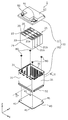
- FIG. 2 is an exploded perspective view showing each component when the power storage device according to the embodiment is disassembled.
- FIG. 3 is a perspective view showing the inside of the exterior body according to the embodiment.
- FIG. 4 is a perspective view of the power storage device according to the embodiment when viewed from diagonally below.
- FIG. 5 is a bottom view showing the relationship between the positions and sizes of the reinforcing member and the power storage element unit according to the embodiment.
- FIG. 6 is a cross-sectional view of a fixed portion of the reinforcing member in the exterior body according to the embodiment.
- FIG. 7 is a perspective view showing the configuration of the power storage device according to the first modification of the embodiment.
- FIG. 1 is a perspective view showing the appearance of the power storage device according to the embodiment.
- FIG. 2 is an exploded perspective view showing each component when the power storage device according to the embodiment is disassembled.
- FIG. 3 is a
- FIG. 8 is a diagram showing a cross-sectional shape of the reinforcing member according to the first modification of the embodiment.
- FIG. 9 is a perspective view showing the configuration of the power storage device according to the second modification of the embodiment.
- FIG. 10 is a diagram showing a cross-sectional shape of the reinforcing member according to the second modification of the embodiment.
- the power storage device accommodates a power storage element unit composed of a plurality of power storage elements arranged in the first direction, and the power storage element unit inside, and the power storage element unit is electrically charged.
- the reinforcement is provided with an exterior body having an external electrode terminal connected to the outer surface, and a reinforcing member arranged along a wall portion partitioning the inside and the outside of the exterior body and fixed to the exterior body.
- the member is composed of a plate-shaped reinforcing main body portion formed in a size covering the power storage element unit and the power storage element unit. Also includes a protruding portion protruding outward.
- the power storage device has a reinforcing member arranged along the wall portion of the exterior body, and the reinforcing member protrudes (protrudes) from the power storage element unit when viewed from the side of the power storage element unit. It has a protruding part. Therefore, when some object collides with the power storage device from the protrusion direction of the protrusion, the protrusion can be impacted before the power storage element unit is impacted, and the plate-shaped reinforcing main body is thickened. The impact can be absorbed in the direction orthogonal to the direction. As a result, the entire plurality of power storage elements included in the power storage element unit can be efficiently protected. As described above, the power storage device according to this aspect is a power storage device with improved safety.
- the protruding portion may project outward from the power storage element unit in the first direction.
- the long side surfaces of the plurality of power storage elements are arranged in a posture facing the first direction.
- the protruding portion is arranged so as to project outward from the power storage element unit in the first direction.
- the long side surface which is a low-strength portion of these power storage elements, is protected from impact. Therefore, the safety of the power storage device is improved.
- the wall portion may be a bottom wall portion on which the power storage element unit is placed on the inner surface.
- the reinforcing member when the reinforcing member is made of high-strength metal, even if the power storage device is deformed due to a collision or the like, the bus bar or the like electrically connected to the power storage element unit can be used. The problem of continuity with the reinforcing member is unlikely to occur. This is advantageous for improving the safety of the power storage device.
- the reinforcing member may be arranged within the outer edge of the exterior body when viewed from the second direction.
- the reinforcing member is provided in a manner of suppressing an increase in the overall size of the exterior body. Therefore, when the exterior body is formed in a size according to some standard, the reinforcing member can be accommodated within that size. Therefore, a power storage device with improved practicality and safety can be obtained.
- the reinforcing member may be arranged along the outer surface of the wall portion.
- the reinforcing member since the reinforcing member is arranged on the outside of the exterior body, the reinforcing member can be arranged without consuming the internal volume of the exterior body. The problem of continuity between the metal reinforcing member and the power storage element unit is unlikely to occur. It is also possible to retrofit a reinforcing member to the finished product as a power storage device. Thereby, the reinforcing member having a shape or size according to the arrangement position or the arrangement environment of the power storage device can be selected and arranged on the exterior body. Therefore, a power storage device with improved practicality and safety can be obtained.
- the protruding portion may be provided along the outer surface of another wall portion adjacent to the wall portion.
- the reinforcing member has, for example, a reinforcing main body portion along the bottom wall portion and a protruding portion along the side wall portion, for example, the reinforcing member has a peripheral edge portion having an L-shaped cross section. Therefore, the strength of the reinforcing member is improved. This improves the safety of the power storage device.
- the power storage device accommodates a power storage element unit composed of a plurality of power storage elements arranged in the first direction, and the power storage element unit inside, and the power storage element unit is electrically charged.
- the reinforcement is provided with an exterior body having an external electrode terminal connected to the outer surface, and a reinforcing member arranged along a wall portion partitioning the inside and the outside of the exterior body and fixed to the exterior body.
- the member is a protruding portion that protrudes outward from the power storage element unit when viewed from the second direction, which is the arrangement direction of the wall portion and the reinforcing member, and is another wall portion adjacent to the wall portion. It may include protrusions arranged along the outer surface of the.
- the reinforcing member has a portion along the wall portion and a protruding portion along the other wall portion, for example, the reinforcing member has a peripheral portion having an L-shaped cross section. Therefore, the strength of the reinforcing member is improved, and the reinforcing member can be attached so as to cover the outer periphery of the wall portion. That is, the reinforcing member can be easily retrofitted to the exterior body, and as a result, the safety of the power storage device can be improved.
- the exterior body may be made of resin, and the reinforcing member may be made of metal.
- the exterior body is made of resin, it can be easily formed into a shape according to the installation location or purpose of use of the power storage device, and the internal power storage element or the like and the external conductive member are electrically connected. Easy to insulate. Since the reinforcing member is made of metal, it is highly effective in protecting or reinforcing the resin exterior body.
- the direction in which a plurality of power storage elements are arranged is defined as the Y-axis direction.
- the direction in which the electrode terminals are arranged in one power storage element or the direction opposite to the short side surface of the container of the power storage element is defined as the X-axis direction.
- the Z-axis direction is defined as the alignment direction of the main body and the lid in the exterior body of the power storage device, the longitudinal direction of the short side surface, or the vertical direction.
- the X-axis direction, the Y-axis direction, and the Z-axis direction are directions that intersect each other (hereinafter, orthogonal to each other in the embodiment and its modifications). Depending on the usage mode, the Z-axis direction may not be the vertical direction, but for convenience of explanation, the Z-axis direction will be described below as the vertical direction.
- expressions indicating relative directions or postures such as parallel and orthogonal may be used, but these expressions include cases where they are not strictly the directions or postures.
- the fact that two directions are parallel not only means that the two directions are completely parallel, but also that they are substantially parallel, that is, that they include a difference of, for example, about several percent. Also means.
- the plus side in the X-axis direction indicates the arrow direction side of the X-axis
- the minus side in the X-axis direction indicates the side opposite to the plus side in the X-axis direction.
- the Y-axis direction and the Z-axis direction indicates the arrow direction side of the X-axis
- the minus side in the X-axis direction indicates the side opposite to the plus side in the X-axis direction.
- FIG. 1 is a perspective view showing the appearance of the power storage device 1 according to the embodiment.
- FIG. 2 is an exploded perspective view showing each component when the power storage device 1 according to the embodiment is disassembled.
- the power storage device 1 is a device that can charge electricity from the outside and discharge electricity to the outside.
- the power storage device 1 is used as a battery for driving a moving body such as an automobile, a motorcycle, a watercraft, a snowmobile, an agricultural machine, a construction machine, or a railroad vehicle for an electric railway, or for starting an engine. Used.
- a moving body such as an automobile, a motorcycle, a watercraft, a snowmobile, an agricultural machine, a construction machine, or a railroad vehicle for an electric railway, or for starting an engine.
- Examples of the above-mentioned vehicle include an electric vehicle (EV), a hybrid electric vehicle (HEV), a plug-in hybrid electric vehicle (PHEV), and a gasoline vehicle.
- Examples of railway vehicles for electric railways include trains, monorails, and linear motor cars.
- the power storage device 1 is also used as a stationary battery or the like used for home use, a generator, or the like.
- the power storage device 1 includes a plurality of power storage elements 20 and an exterior body 10 accommodating the plurality of power storage elements 20.
- four power storage elements 20 arranged in the Y-axis direction are housed in the exterior body 10, and one power storage element unit 25 is configured by these four power storage elements 20.
- the Y-axis direction is an example of the first direction.
- the number of power storage elements 20 included in the power storage device 1 is not limited to 4.
- the power storage device 1 may include a plurality of power storage elements 20.
- the exterior body 10 has an exterior body body 30 that houses the power storage element unit 25, and a lid 11 that closes the opening of the exterior body body 30 in which the power storage element unit 25 is housed. Between the power storage element unit 25 and the lid 11, a bus bar that electrically connects two or more power storage elements 20, a bus bar plate that holds a plurality of bus bars, and a bus bar plate and the lid 11 are arranged. Control circuits and the like are arranged, but their illustrations are omitted.
- the exterior body 10 is a rectangular (box-shaped) container (module case) that constitutes the outer shell of the power storage device 1. That is, the exterior body 10 is a member that fixes the power storage element unit 25 and the like at predetermined positions and protects them from impacts and the like.
- the exterior body 10 includes, for example, polycarbonate (PC), polypropylene (PP), polyethylene (PE), polystyrene (PS), polyphenylene sulfide resin (PPS), polyphenylene ether (PPE (including modified PPE)), polyethylene terephthalate (including modified PPE).
- PET polybutylene terephthalate
- PEEK polyetheretherketone
- PFA tetrafluoroethylene / perfluoroalkylvinyl ether
- PES polyethersulfone
- ABS resin or , It is formed of insulating members such as those composite materials.
- the exterior body body 30 included in the exterior body 10 is a container composed of a plurality of wall portions formed by the above-mentioned insulating members, and insulates the power storage element unit 25 and the like from the outside.
- the plurality of wall portions include a pair of side wall portions 31 facing in the X-axis direction, a pair of side wall portions 31 facing in the Y-axis direction, and a bottom wall portion 32 located on the minus side in the Z-axis direction.
- the lid 11 included in the exterior body 10 is a rectangular member that closes the opening of the exterior body body 30, and is fixed to the exterior body body 30 by a predetermined method such as welding or adhesion.
- the upper wall portion 12, which is a part of the lid body 11, functions as a wall portion that separates the inside and the outside of the exterior body 10, like the four side wall portions 31 and one bottom wall portion 32 of the exterior body body 30. ..
- An external electrode terminal 91 on the positive electrode side and an external electrode terminal 92 on the negative electrode side are arranged on the outer surface of the lid 11.
- the external electrode terminals 91 and 92 are electrically connected to the power storage element unit 25 via a bus bar or the like, and the power storage device 1 charges electricity from the outside via the external electrode terminals 91 and 92. It also discharges electricity to the outside.
- the external electrode terminals 91 and 92 are formed of, for example, a conductive member made of metal such as aluminum or an aluminum alloy.
- the power storage element 20 is a secondary battery (single battery) capable of charging electricity and discharging electricity, and more specifically, a non-aqueous electrolyte secondary battery such as a lithium ion secondary battery.
- the power storage element 20 has a flat rectangular parallelepiped shape (square shape), and has a pair of long side surfaces 21a facing each other and a pair of short side surfaces 21b facing each other.
- the four power storage elements 20 are arranged in the Y-axis direction with the long side surface 21a facing the Y-axis direction.
- the power storage element 20 is not limited to the non-aqueous electrolyte secondary battery, and may be a secondary battery other than the non-aqueous electrolyte secondary battery, or may be a capacitor.
- the power storage element 20 may be a primary battery that can use the stored electricity without being charged by the user.
- the power storage element 20 may be a battery using a solid electrolyte.
- the power storage element 20 includes a metal container 21, and a pair of metal electrode terminals 22 (positive electrode terminal and negative electrode terminal) are provided on the lid portion of the container 21.
- the pair of electrode terminals 22 (positive electrode terminal and negative electrode terminal) are arranged so as to project from the lid portion of the container 21 toward the lid 11 side (upward, that is, toward the positive side in the Z-axis direction).
- An electrode body also referred to as a power storage element or a power generation element
- a current collector positive electrode current collector and negative electrode current collector
- an electrolytic solution non-aqueous electrolyte
- the four power storage elements 20 included in the power storage element unit 25 are connected in series by, for example, three bus bars (not shown).
- the bus bar is, for example, a conductive member made of metal such as copper, copper alloy, aluminum, and aluminum alloy.
- the mode of electrical connection of the four power storage elements 20 is not particularly limited, and two power storage elements 20 are connected in parallel to form two sets of power storage element groups, and the two sets of power storage element groups are formed. May be connected in series.
- the reinforcing member 40 is arranged on the exterior body 10.
- the reinforcing member 40 is a member made of a high-strength material such as iron, and has a function of enhancing the impact resistance of the power storage device 1.
- the reinforcing member 40 is arranged along the bottom wall portion 32 of the exterior body 10, and the reinforcing member 40 is fixed to the exterior body 10 by four bolts 80. There is.
- the details of the reinforcing member 40 according to the embodiment will be described with reference to FIGS. 3 to 6.
- FIG. 3 is a perspective view showing the inside of the exterior body 10 according to the embodiment.
- the power storage device 1 is shown in a state where the exterior body body 30 is cut along the YZ plane passing through the line II-II of FIG. 2 and the power storage element unit 25 is lifted, and the lid 11 is not shown. It has been omitted.
- FIG. 4 is a perspective view of the power storage device 1 according to the embodiment when viewed from diagonally below.
- the reinforcing member 40 is shown by removing it from the bottom wall portion 32 of the exterior body 10, and the approximate boundary between the reinforcing main body portion 45 and the protruding portion 46 is shown by a dotted line.
- FIG. 5 is a bottom view showing the relationship between the positions and sizes of the reinforcing member 40 and the power storage element unit 25 according to the embodiment.
- the exterior body 10 is not shown, and the reinforcing member 40 is seen through, and the outer shape of the power storage element unit 25 (four power storage elements 20) is shown by a dotted line.
- Each of the four power storage elements 20 is represented by a dotted area so as to be easily distinguished from other elements, and the approximate boundary between the reinforcing main body portion 45 and the protruding portion 46 is shown by a two-dot chain line.
- FIG. 6 is a cross-sectional view of a fixed portion of the reinforcing member 40 in the exterior body 10 according to the embodiment. In FIG. 6, a partial cross section of the power storage device 1 in the YZ plane passing through the VI-VI line of FIG. 3 is shown, and the mounting portion 33 on which the power storage element 20 is mounted is not shown. ..
- the power storage device 1 includes a reinforcing member 40 arranged along the wall portion of the exterior body 10.
- the reinforcing member 40 is arranged along the outer surface 32a of the bottom wall portion 32 of the exterior body 10.
- "Reinforcing member is arranged along the wall portion” means that the reinforcing member is arranged in a posture parallel to the wall portion and at a position inside or near the wall portion (between the inner surface and the outer surface). This means that the reinforcing member is separated from the wall portion by about several millimeters.
- the bottom wall portion 32 of the exterior body body 30 is provided with four through holes 32b penetrating the bottom wall portion 32, and the four through holes 32b are provided.
- Bolts 80 are arranged through each of the bolts 80.
- the reinforcing member 40 has four mounting holes 41 at positions corresponding to the four through holes 32b, and the shaft portion 81 of the bolt 80 is screwed into each of the four mounting holes 41.
- the power storage device 1 provided with the reinforcing member 40 is installed on the installation surface 200 in a posture in which the reinforcing member 40 faces the installation surface 200 (see FIG. 6).
- a gasket 85 is fitted in each of the four through holes 32b, and the shaft portion 81 of the bolt 80 is screwed into the mounting hole 41 of the reinforcing member 40 so that the head portion 82 of the bolt 80 is inserted. Compresses the gasket 85 in the axial direction. As a result, the airtightness in the through hole 32b is maintained. Further, the head 82 of the penetrating member 80 and the gasket 85 exposed inside the exterior body 10 may be covered and hardened with an adhesive or the like. As a result, the airtightness of the through hole 32b of the exterior body 10 is further improved.
- the bolt 80 is a metal member such as iron, aluminum or stainless steel, and has relatively high conductivity and thermal conductivity.
- the mounting hole 41 is a bottomless hole and penetrates the reinforcing member 40, but the mounting hole 41 may be a bottomed hole that does not penetrate the reinforcing member 40.
- the bottom wall portion 32 of the exterior body 10 has a mounting portion 33 on which the power storage element unit 25 is mounted.
- the mounting portion 33 is provided on the bottom wall portion 32 as a portion protruding inward of the exterior body 10, and the outer surface 32a of the bottom wall portion 32 has the shape and size of the mounting portion 33.
- the corresponding recess 33a is formed.
- each of the four bolts 80 can be arranged at a position overlapping the power storage element unit 25 in the top view, and the metal bolt 80 and the power storage element unit 25 can be separated from each other.
- a plurality of ribs 35 are arranged inside the recess 33a formed on the back side of the mounting portion 33, whereby the mechanical strength of the mounting portion 33 is improved.
- the method of fixing the power storage element unit 25 to the mounting portion 33 is not particularly limited, but for example, the bottom surface of the power storage element unit 25 is adhered to the mounting portion 33 by an adhesive.
- the power storage device 1 accommodates the power storage element unit 25 composed of a plurality of power storage elements 20 arranged in the first direction (Y-axis direction) and the power storage element unit 25 inside.
- the exterior body 10 and the reinforcing member 40 fixed to the exterior body 10 are provided.
- the exterior body 10 has external electrode terminals 91 and 92 electrically connected to the power storage element unit 25 on the outer surface.
- the reinforcing member 40 is arranged along the bottom wall portion 32 which is a wall portion that separates the inside and the outside of the exterior body 10.
- the reinforcing member 40 arranged in this way includes the reinforcing main body portion 45 and the protruding portion 46.
- the reinforcing main body portion 45 is formed in a size that covers the power storage element unit 25 when the reinforcing member 40 is viewed from the second direction (Z-axis direction), which is the alignment direction of the bottom wall portion 32 and the reinforcing member 40. It is a plate-shaped part.
- the protruding portion 46 is a portion that protrudes outward from the power storage element unit 25 when the reinforcing member 40 is viewed from the second direction (Z-axis direction).
- the reinforcing member 40 arranged on the exterior body 10 of the power storage device 1 protrudes (protrudes) from the power storage element unit 25 when viewed from the side of the power storage element unit 25. It has a part 46. Therefore, when some object collides with the power storage device 1 from the protrusion direction of the protrusion 46, the protrusion 46 can be impacted before the power storage element unit 25 is impacted. Further, since the reinforcing member 40 has a plate-shaped reinforcing main body 45 inside the protruding portion 46, the reinforcing main body 45 can absorb the impact in the direction orthogonal to the plate thickness direction.
- the entire plurality of power storage elements 20 included in the power storage element unit 25 can be efficiently protected.
- the power storage element unit 25 not only the power storage element unit 25, but also the bus bar, the control circuit, and the like located inside the reinforcing member 40 when viewed from the second direction (Z-axis direction) are the reinforcing member 40 when the power storage device 1 is impacted. Can be protected by.
- the power storage device 1 according to this aspect is a power storage device with improved safety.
- a plurality of exterior bodies 10 having a predetermined shape and size are manufactured, and reinforcing members having different sizes or shapes are fixed to each of the plurality of exterior bodies 10, and the reinforcing members are fixed to each of the plurality of exterior bodies 10. It is possible not to.
- the specifications for the reinforcing members are mutually different.
- a plurality of different types of power storage devices 1 can be obtained. That is, it is easy to manufacture a plurality of power storage devices 1 that meet each of the plurality of requirements.
- the reinforcing member can be integrated with the bottom wall portion 32 by insert molding described later, but the reinforcing member can be fixed to the molded exterior body 10 later. is there.
- the cost of insert molding may be high in the manufacturing process, and the manufacturing cost of the power storage device 1 may be suppressed by fixing the reinforcing member to the molded exterior body 10 later.
- the protruding portion 46 of the reinforcing member 40 projects outward from the power storage element unit 25 in the first direction (Y-axis direction), which is the arrangement direction of the plurality of power storage elements 20.
- the power storage element unit 25 As shown in FIG. 3, four power storage elements 20 are arranged in the Y-axis direction with their long side surfaces 21a facing the Y-axis direction.
- the protruding portion 46 is arranged so as to project outward from the power storage element unit 25 in the Y-axis direction.
- the long side surface 21a which is a low-strength portion of the power storage element 20, is protected from impact. Therefore, the safety of the power storage device 1 is improved.
- the protruding portion 46 is from the power storage element unit 25 even in the X-axis direction orthogonal to the first direction (Y-axis direction), that is, in the direction facing the short side surfaces 21b of each of the four power storage elements 20. Is also arranged so as to project outward.
- the reinforcing member 40 can collectively protect the four power storage elements 20 included in the power storage element unit 25 from an impact from the outside.
- the wall portion on which the reinforcing member 40 is arranged is the bottom wall portion 32 on which the power storage element unit 25 is placed on the inner surface.
- the reinforcing member 40 is made of a high-strength metal such as iron.
- the reinforcing member 40 and the conductive member inside the exterior body 10 may come into contact with each other to conduct conduction.
- the reinforcing member 40 is arranged on the bottom wall portion 32 on which the power storage element unit 25 is placed on the inner surface. Therefore, the problem of continuity between the bus bar or the like electrically connected to the power storage element unit 25 and the reinforcing member 40 is unlikely to occur. This is advantageous for improving the safety of the power storage device 1.
- the reinforcing member 40 is arranged inside the outer edge of the exterior body 10 when viewed from the second direction (Z-axis direction).
- the exterior body body 30 has an outer edge portion 36 provided on the outer periphery of the bottom wall portion 32, and the reinforcing member 40 has the outer edge portion 36. It is located inside the. That is, the reinforcing member 40 according to the present embodiment is projected from the power storage element unit 25 and not from the exterior body 10 when viewed from the second direction (Z-axis direction). Have been placed.
- the reinforcing member 40 is provided in a manner of suppressing an increase in the overall size of the exterior body 10. Therefore, when the exterior body 10 is formed to a size according to some standard, the reinforcing member 40 can be accommodated within that size. Therefore, the power storage device 1 with improved practicality and safety can be obtained.
- the reinforcing member 40 may have a portion protruding outward from the outer edge of the exterior body 10 when viewed from the second direction (Z-axis direction).
- the protrusion 46 may be provided along the outer surface of the side wall portion 31, which is another wall portion adjacent to the bottom wall portion 32.
- the reinforcing member 40 since the reinforcing member 40 has a reinforcing main body portion 45 along the bottom wall portion 32 and a protruding portion 46 along the side wall portion 31, for example, the reinforcing member 40 has a peripheral edge portion having an L-shaped cross section. Therefore, the strength of the reinforcing member 40 is improved. As a result, the safety of the power storage device 1 is improved.
- Another example of the reinforcing member having an L-shaped peripheral edge portion will be described later as a modified example 1.
- the reinforcing member 40 is arranged along the outer surface 32a of the bottom wall portion 32.
- the reinforcing member 40 can be arranged without consuming the internal volume of the exterior body 10.
- the problem of continuity between the metal reinforcing member 40 and the power storage element unit 25 is unlikely to occur.
- a structure in which a bolt is inserted from the outside is adopted for fixing the reinforcing member 40 to the exterior body 10
- the reinforcing member 40 having a shape or size according to the arrangement position or arrangement environment of the power storage device 1 can be selected and arranged on the exterior body 10. Therefore, the power storage device 1 with improved practicality and safety can be obtained.
- the configuration of the reinforcing member arranged on the exterior body 10 may be different from the configuration shown in FIGS. 2 to 6. Therefore, a power storage device including a reinforcing member having a configuration different from that of the above embodiment will be described below with reference to modifications 1 and 2 focusing on the difference from the above embodiment.
- FIG. 7 is a perspective view showing the configuration of the power storage device 1a according to the first modification of the embodiment.
- the reinforcing members 60 and 70 included in the power storage device 1a are removed from the exterior body 10 and shown.
- FIG. 8 is a diagram showing a cross-sectional shape of the reinforcing member 60 according to the first modification of the embodiment.
- FIG. 8 shows a partial cross section of the power storage device 1a in the XZ plane passing through the line VIII-VIII of FIG.
- the power storage device 1a according to this modification includes an exterior body 10, and a power storage element unit 25 (see, for example, FIG. 2) is housed inside the exterior body 10.
- the exterior body 10 includes external electrode terminals 91 and 92 arranged on the outer surface.
- the power storage device 1a according to the present modification is common to the power storage device 1 according to the embodiment.
- the reinforcing members 60 and 70 are attached to the exterior body 10, and the reinforcing members 60 and 70 have different characteristics in the protruding portion from the protruding portion 46 according to the embodiment.
- the reinforcing member 60 is arranged along the upper wall portion 12, which is a wall portion that separates the inside and the outside of the exterior body 10, and stores electricity when viewed from the second direction (Z-axis direction). It has a protruding portion 66 that protrudes outward from the element unit 25.
- the protruding portion 66 is arranged along the outer surface of another wall portion (upper side wall portion 13 in this modified example) adjacent to the upper wall portion 12.
- the upper side wall portion 13 is a wall portion forming the side surface of the lid 11.
- the reinforcing member 60 has a reinforcing main body portion 65 arranged along the upper wall portion 12 and a protruding portion 66 arranged along the upper side wall portion 13 adjacent to the upper wall portion 12. ing.
- the reinforcing main body portion 65 is formed in an annular shape along the peripheral edge of the upper wall portion 12, the reinforcing member 60 is attached to the exterior body 10 to the external electrode terminals 91 and 92. Work such as attaching and detaching cables is possible.
- the reinforcing member 60 configured in this way has an L-shaped cross section orthogonal to the extending direction. Therefore, the strength is improved as compared with the case where the protruding portion 66 is not provided.
- the reinforcing main body portion 65 of the reinforcing member 60 protrudes from the power storage element unit 25 when viewed from the second direction (Z-axis direction), which is the alignment direction of the upper wall portion 12 and the reinforcing member 60. Has a part that has been removed. Therefore, when an impact is applied to the power storage device 1a from the side, this protruding portion can receive the shock before the power storage element unit 25.
- Z-axis direction the second direction
- the reinforcing main body portion 65 according to the present modification is formed in an annular shape having an opening in the center, and is compared with the plate-shaped reinforcing main body portion 45 having no opening (see FIG. 4). , Weak against force from the direction orthogonal to the thickness direction (direction parallel to the XY plane). Therefore, in this modification, a protruding portion 66 extending in a direction intersecting the reinforcing main body 65 is provided on the outer periphery of the reinforcing main body 65, whereby the strength of the reinforcing member 60 is improved, and as a result, the strength of the reinforcing member 60 is improved.
- the effectiveness of the reinforcing member 60 as a member for improving the safety of the power storage device 1a is also improved.
- the protruding portion 66 is not only a portion erected downward from the peripheral edge of the reinforcing main body portion 65, but also a part of the reinforcing main body portion 65, and is a power storage element when viewed from the second direction (Z-axis direction). A portion protruding (protruding) from the unit 25 may be included.
- the power storage device 1a further includes a reinforcing member 70 arranged along the bottom wall portion 32 of the exterior body 10.
- the reinforcing member 70 is arranged along the bottom wall portion 32, which is a wall portion that separates the inside and the outside of the exterior body 10, and is more than the power storage element unit 25 when viewed from the second direction (Z-axis direction). It has a protruding portion 76 that protrudes outward.
- the protruding portion 76 is arranged along the outer surface of another wall portion (side wall portion 31 in this modification) adjacent to the bottom wall portion 32.
- the reinforcing member 70 has a reinforcing main body portion 75 facing the bottom wall portion 32, and a protruding portion 76 is erected upward from the peripheral edge of the reinforcing main body portion 75. That is, like the reinforcing member 60, the reinforcing member 70 also has a portion having an L-shaped cross section on the outer peripheral portion, whereby the strength of the reinforcing member 70 is improved.
- each of the reinforcing members 60 and 70 has a peripheral edge portion having an L-shaped cross section, the strength is improved and the outer peripheral portion of the bottom wall portion 32 or the upper wall portion 12 is covered. Can be installed like this. That is, the reinforcing members 60 and 70 can be easily retrofitted to the exterior body 10, and as a result, the safety of the power storage device 1a can be improved.
- Each of the reinforcing members 60 and 70 may be fixed to the exterior body 10 with an adhesive, screws, or the like, but it is not essential that the reinforcing members 60 and 70 are fixed to the exterior body 10. That is, each of the reinforcing members 60 and 70 may be attached to the exterior body 10 with an engaging force that does not easily come off.
- FIG. 9 is a perspective view showing the configuration of the power storage device 1b according to the second modification of the embodiment.
- the reinforcing member 140 included in the power storage device 1b is removed from the exterior body 10 and shown, and the power storage element unit 25 and the lid 11 are not shown.
- FIG. 10 is a diagram showing a cross-sectional shape of the reinforcing member 140 according to the second modification of the embodiment. In FIG. 10, a cross section of a part of the power storage device 1b in the XZ plane passing through the XX line of FIG. 9 is shown.
- the power storage device 1b includes an exterior body 10 that houses the power storage element unit 25.
- a reinforcing member 140 arranged along the bottom wall portion 32 of the exterior body 10 is fixed to the exterior body 10.
- the reinforcing member 140 is a plate-shaped reinforcing main body formed in a size that covers the power storage element unit 25 when viewed from the second direction (Z-axis direction), which is the arrangement direction of the bottom wall portion 32 and the reinforcing member 140.
- a portion 145 and a protruding portion 146 projecting outward from the power storage element unit 25 are included.
- the reinforcing member 140 according to the present modification and the reinforcing member 40 according to the embodiment are common.
- the reinforcing member 140 has a flat plate portion 142 that abuts on the installation surface 200 and a connecting portion 143 that is fixed to the flat plate portion 142 and connected to the bolt 80. doing.
- the flat plate portion 142 and the connecting portion 143 are joined by welding, for example.
- connection portion 143 in which a relatively thin metal plate is adopted as the flat plate portion 142 and has a mounting hole 141 suitable for connection with the bolt 80 is manufactured as a separate member from the flat plate portion 142. it can. Therefore, the flat plate portion 142 and the connecting portion 143 can be made of different materials. As shown in FIG. 10, since the tip of the shaft portion 81 of the bolt 80 can be projected downward from the connecting portion 143, the connecting portion 143 can also be formed of a relatively thin plate material. That is, the entire reinforcing member 140 can be formed of a relatively thin plate material.
- the reinforcing member 140 according to the present modification is a member that can improve the safety of the power storage device 1b and has a high degree of freedom regarding the material used for production.
- connection portion 143 the portion of the mounting hole 141 connected to the bolt 80 may be formed to be thicker than the others.
- the connecting portion 143 may be provided with a mounting hole 141 connected to the bolt 80 by having a nut welded to the bent plate-shaped connecting portion main body.
- the connecting portion 143 connected to the bolt 80 has a shape bent so as to separate the mounting hole 141 from the flat plate portion 142. ..
- the reinforcing member 140 is fixed to the exterior body 10 in a state where the flat plate portion 142 floats from the outer surface 32a of the bottom wall portion 32.
- a clear gap is formed between the flat plate portion 142 and the outer surface 32a of the bottom wall portion 32.
- the gap between the flat plate portion 142 and the bottom wall portion 32 can be used as a space for bending in the thickness direction (Z-axis direction) of the flat plate portion 142.
- the flat plate portion 142 bends (deforms) so as to approach the bottom wall portion 32, so that the transmission of the impact to the exterior body 10 is suppressed.
- the gap between the flat plate portion 142 and the bottom wall portion 32 serves as a flow path for a fluid such as air that exchanges heat with the power storage device 1b, so that the heat dissipation efficiency of the power storage device 1b can be improved.
- the material of the reinforcing member 40 does not have to be a metal such as iron.
- the reinforcing member 40 may be formed of a resin having a strength higher than that of the material forming the exterior body 10. As a result, the weight of the reinforcing member 40 can be reduced.
- the wall portion on which the reinforcing member is arranged is not limited to the bottom wall portion 32, and the reinforcing member may be arranged along the upper wall portion 12 or the side wall portion 31.
- the reinforcing member has a plate-shaped reinforcing main body portion formed to cover the power storage element unit 25 and a protruding portion protruding outward from the power storage element unit 25. The effect of shock absorption or mitigation by the reinforcing member can be obtained.
- the reinforcing member is arranged along any one of the pair of side wall portions 31 (see FIG. 2) facing each other in the Y-axis direction of the exterior body 10, the arrangement direction (first direction) of the plurality of power storage elements 20 and The alignment direction (second direction) of the reinforcing member and the wall portion coincides with each other.
- the reinforcing member may be arranged inside the wall portion (between the outer surface and the inner surface).
- a reinforcing member integrated with the bottom wall portion 32 by insert molding may be arranged on the exterior body 10.
- a reinforcing member may be sandwiched between layers of the wall portion divided into two layers in the thickness direction. In either case, since the bolt 80 for fixing the reinforcing member to the exterior body 10 is unnecessary, the number of parts or the weight of the power storage device 1 can be reduced.
- the reinforcing member may be arranged inside the wall portion (inside the exterior body 10). For example, a reinforcing member may be arranged between the bottom wall portion 32 and the power storage element unit 25.
- the reinforcing member and the power storage element unit 25 can be electrically insulated by arranging an insulating sheet or the like between the reinforcing member and the power storage element unit 25. Further, by inserting the bolt 80 into the through hole 32b from the outer surface 32a side of the bottom wall portion 32, the reinforcing member arranged inside the exterior body 10 can be fixed by the bolt 80.
- the plate-shaped reinforcing main body 45 included in the reinforcing member 40 needs to completely cover the power storage element unit 25 without any gap when viewed from the arranged wall portion and the arrangement direction (second direction) of the power storage element unit. There is no.
- the reinforcing main body 45 may have an opening (through hole) for fixing the reinforcing member 40 to the installation surface 200 within a range overlapping the power storage element unit 25.
- the reinforcing main body 45 may have a plurality of dispersed openings (through holes) for weight reduction.
- the reinforcing main body portion 45 may be provided with an opening, a through hole, a thin-walled portion, or the like so as not to unnecessarily lose the function of absorbing the impact received by the protruding portion 46.
- the reinforcing member 40 does not have to be flat on both sides in the thickness direction, and a bent portion or rib or the like for improving strength may be formed on at least one of the both sides.
- the various supplementary items regarding the reinforcing member 40 may be applied to the reinforcing members 60, 70, and 140 according to the first and second modifications.
- the power storage element unit 25 may include elements other than the power storage element 20, such as spacers arranged along each of the plurality of power storage elements 20 and / and a bus bar connected to at least one power storage element 20.
- Each of the plurality of power storage elements 20 may have an insulating film that covers the outer periphery.
- the present invention can be applied to a power storage device provided with a power storage element such as a lithium ion secondary battery.
- Power storage device 10 Exterior body 11 Lid body 12 Upper wall part 13 Upper side wall part 20 Power storage element 25 Power storage element unit 30 Exterior body 31 Side wall part 32 Bottom wall part 32a Outer surface 36 Outer edge part 40, 60, 70, 140 Reinforcing member 41, 141 Mounting holes 45, 65, 75, 145 Reinforcing body part 46, 66, 76, 146 Protruding part 80 Bolt 91, 92 External electrode terminal 200 Installation surface
Abstract
A power storage device (1) is provided with: an electrical storage element unit (25) composed of a plurality of electrical storage elements (20) arranged in a first direction; an outer case (10); and a reinforcement member (40) fixed to the outer case (10). The outer case (10) has an outer surface on which outer electrode terminals (91 and 92) electrically connected to the electrical storage element unit (25) are disposed. The reinforcement member (40) is disposed along a bottom wall portion (32) which is a wall portion separating the inside and outside of the outer case (10). The reinforcement member (40) includes a reinforcement body portion (45) and a protruding portion (46). The reinforcement body portion (45) is a plate-like portion sized to cover the electrical storage element unit (25) when the reinforcement member (40) is viewed from a second direction in which the bottom wall portion (32) and the reinforcement member (40) are arranged. The protruding portion (46) is a portion protruding on the outside of the electrical storage element unit (25) when the reinforcement member (40) is viewed from the second direction.
Description
本発明は、複数の蓄電素子により構成された蓄電素子ユニットを備える蓄電装置に関する。
The present invention relates to a power storage device including a power storage element unit composed of a plurality of power storage elements.
従来、複数の蓄電素子を備える蓄電装置が知られている。例えば特許文献1には、2つ以上の蓄電デバイスを一体化する絶縁性を有するホルダーを備える蓄電デバイスモジュールが開示されている。特許文献1では、蓄電デバイスモジュールは、ホルダーを備えることで、全体的に取り扱い易い形状となり、機械的もしくは構造的な強度が向上する旨が記載されている。
Conventionally, a power storage device including a plurality of power storage elements is known. For example, Patent Document 1 discloses a power storage device module including a holder having an insulating property that integrates two or more power storage devices. Patent Document 1 describes that, by providing a holder, the power storage device module has a shape that is easy to handle as a whole and has improved mechanical or structural strength.
蓄電装置において、特許文献1のように、複数の蓄電素子を側方から囲むホルダーを設けた場合、ホルダーを備えない場合よりも耐衝撃性は向上する。しかし、蓄電素子に側方から衝撃が与えられた場合、ホルダーを構成する壁部に、その厚み方向から衝撃荷重が加えられるため、ホルダーに変形が生じやすい。
When a holder that surrounds a plurality of power storage elements from the side is provided in the power storage device as in Patent Document 1, the impact resistance is improved as compared with the case where the holder is not provided. However, when an impact is applied to the power storage element from the side, an impact load is applied to the wall portion constituting the holder from the thickness direction thereof, so that the holder is likely to be deformed.
本発明は、本願発明者が上記課題に新たに着目することによってなされたものであり、複数の蓄電素子を備える蓄電装置であって、安全性が向上された蓄電装置を提供することを目的とする。
The present invention has been made by the inventor of the present application paying new attention to the above problems, and an object of the present invention is to provide a power storage device provided with a plurality of power storage elements and having improved safety. To do.
本発明の一態様に係る蓄電装置は、第一方向に並べられた複数の蓄電素子により構成された蓄電素子ユニットと、内部に前記蓄電素子ユニットを収容し、かつ、前記蓄電素子ユニットに電気的に接続された外部電極端子を外面に有する外装体と、前記外装体の内部と外部とを仕切る壁部に沿って配置され、かつ、前記外装体に固定された補強部材とを備え、前記補強部材は、前記壁部と前記補強部材との並び方向である第二方向から見た場合において、前記蓄電素子ユニットを覆う大きさに形成された板状の補強本体部と、前記蓄電素子ユニットよりも外側に突出した突出部とを含む。
The power storage device according to one aspect of the present invention accommodates a power storage element unit composed of a plurality of power storage elements arranged in the first direction, and the power storage element unit inside, and the power storage element unit is electrically charged. The reinforcement is provided with an exterior body having an external electrode terminal connected to the outer surface, and a reinforcing member arranged along a wall portion partitioning the inside and the outside of the exterior body and fixed to the exterior body. When viewed from the second direction, which is the arrangement direction of the wall portion and the reinforcing member, the member is composed of a plate-shaped reinforcing main body portion formed in a size covering the power storage element unit and the power storage element unit. Also includes a protruding portion protruding outward.
本発明の一態様に係る蓄電装置は、第一方向に並べられた複数の蓄電素子により構成された蓄電素子ユニットと、内部に前記蓄電素子ユニットを収容し、かつ、前記蓄電素子ユニットに電気的に接続された外部電極端子を外面に有する外装体と、前記外装体の内部と外部とを仕切る壁部に沿って配置され、かつ、前記外装体に固定された補強部材とを備え、前記補強部材は、前記壁部と前記補強部材との並び方向である第二方向から見た場合において前記蓄電素子ユニットよりも外側に突出する突出部であって、前記壁部に隣接する他の壁部の外面に沿って配置された突出部を含む、としてもよい。
The power storage device according to one aspect of the present invention accommodates a power storage element unit composed of a plurality of power storage elements arranged in the first direction, and the power storage element unit inside, and the power storage element unit is electrically charged. The reinforcement is provided with an exterior body having an external electrode terminal connected to the outer surface, and a reinforcing member arranged along a wall portion partitioning the inside and the outside of the exterior body and fixed to the exterior body. The member is a protruding portion that protrudes outward from the power storage element unit when viewed from the second direction, which is the arrangement direction of the wall portion and the reinforcing member, and is another wall portion adjacent to the wall portion. It may include protrusions arranged along the outer surface of the.
本発明によれば、安全性が向上された蓄電装置を提供できる。
According to the present invention, it is possible to provide a power storage device with improved safety.
本発明の一態様に係る蓄電装置は、第一方向に並べられた複数の蓄電素子により構成された蓄電素子ユニットと、内部に前記蓄電素子ユニットを収容し、かつ、前記蓄電素子ユニットに電気的に接続された外部電極端子を外面に有する外装体と、前記外装体の内部と外部とを仕切る壁部に沿って配置され、かつ、前記外装体に固定された補強部材とを備え、前記補強部材は、前記壁部と前記補強部材との並び方向である第二方向から見た場合において、前記蓄電素子ユニットを覆う大きさに形成された板状の補強本体部と、前記蓄電素子ユニットよりも外側に突出した突出部とを含む。
The power storage device according to one aspect of the present invention accommodates a power storage element unit composed of a plurality of power storage elements arranged in the first direction, and the power storage element unit inside, and the power storage element unit is electrically charged. The reinforcement is provided with an exterior body having an external electrode terminal connected to the outer surface, and a reinforcing member arranged along a wall portion partitioning the inside and the outside of the exterior body and fixed to the exterior body. When viewed from the second direction, which is the arrangement direction of the wall portion and the reinforcing member, the member is composed of a plate-shaped reinforcing main body portion formed in a size covering the power storage element unit and the power storage element unit. Also includes a protruding portion protruding outward.
この構成によれば、蓄電装置は、外装体の壁部に沿って配置された補強部材を有し、補強部材は、蓄電素子ユニットの側から見た場合に、蓄電素子ユニットから突出した(はみ出した)突出部を有している。従って、突出部の突出方向から何等かの物体が蓄電装置に衝突した場合、蓄電素子ユニットが衝撃を受ける前に突出部が衝撃を受けることができ、さらに、板状の補強本体部が板厚方向と直交する方向で衝撃を吸収できる。これにより、蓄電素子ユニットに含まれる複数の蓄電素子の全体を効率よく保護できる。このように本態様に係る蓄電装置は、安全性が向上された蓄電装置である。
According to this configuration, the power storage device has a reinforcing member arranged along the wall portion of the exterior body, and the reinforcing member protrudes (protrudes) from the power storage element unit when viewed from the side of the power storage element unit. It has a protruding part. Therefore, when some object collides with the power storage device from the protrusion direction of the protrusion, the protrusion can be impacted before the power storage element unit is impacted, and the plate-shaped reinforcing main body is thickened. The impact can be absorbed in the direction orthogonal to the direction. As a result, the entire plurality of power storage elements included in the power storage element unit can be efficiently protected. As described above, the power storage device according to this aspect is a power storage device with improved safety.
前記突出部は、前記第一方向において前記蓄電素子ユニットよりも外側に突出している、としてもよい。
The protruding portion may project outward from the power storage element unit in the first direction.
蓄電素子ユニットにおいて、蓄電素子が第一方向に並べられる場合、一般的に、複数の蓄電素子のそれぞれの長側面が第一方向に向く姿勢で並べられる。このように構成された蓄電素子ユニットに対し、突出部が、第一方向において蓄電素子ユニットよりも外側に突出して配置されている。これにより、これら蓄電素子における強度が低い部分である長側面が衝撃から保護される。従って、蓄電装置の安全性が向上される。
In the power storage element unit, when the power storage elements are arranged in the first direction, generally, the long side surfaces of the plurality of power storage elements are arranged in a posture facing the first direction. With respect to the power storage element unit configured in this way, the protruding portion is arranged so as to project outward from the power storage element unit in the first direction. As a result, the long side surface, which is a low-strength portion of these power storage elements, is protected from impact. Therefore, the safety of the power storage device is improved.
前記外装体において、前記壁部は、内面に前記蓄電素子ユニットが載置される底壁部である、としてもよい。
In the exterior body, the wall portion may be a bottom wall portion on which the power storage element unit is placed on the inner surface.
この構成によれば、強度の高い金属で補強部材を形成した場合において、仮に衝突等によって蓄電装置に変形等が生じた場合であっても、蓄電素子ユニットに電気的に接続されたバスバー等と補強部材との導通の問題が生じ難い。このことは、蓄電装置の安全性の向上に有利である。
According to this configuration, when the reinforcing member is made of high-strength metal, even if the power storage device is deformed due to a collision or the like, the bus bar or the like electrically connected to the power storage element unit can be used. The problem of continuity with the reinforcing member is unlikely to occur. This is advantageous for improving the safety of the power storage device.
前記補強部材は、前記第二方向から見た場合において、前記外装体の外縁内に配置されている、としてもよい。
The reinforcing member may be arranged within the outer edge of the exterior body when viewed from the second direction.
この構成によれば、外装体の全体のサイズの増加を抑制する態様で補強部材が設けられる。そのため、外装体が何等かの規格に従ったサイズに形成されている場合、そのサイズ内に補強部材を収めることができる。従って、実用性及び安全性が向上された蓄電装置が得られる。
According to this configuration, the reinforcing member is provided in a manner of suppressing an increase in the overall size of the exterior body. Therefore, when the exterior body is formed in a size according to some standard, the reinforcing member can be accommodated within that size. Therefore, a power storage device with improved practicality and safety can be obtained.
前記補強部材は、前記壁部の外面に沿って配置されている、としてもよい。
The reinforcing member may be arranged along the outer surface of the wall portion.
この構成によれば、外装体の外側に補強部材が配置されるため、外装体の内部の容積を消費せずに補強部材を配置できる。金属製の補強部材と、蓄電素子ユニットとの導通の問題も生じ難い。蓄電装置としての完成品に補強部材を後付けすることも可能である。これにより、蓄電装置の配置位置または配置環境に応じた形状またはサイズの補強部材を選択して外装体に配置できる。従って、実用性及び安全性が向上された蓄電装置が得られる。
According to this configuration, since the reinforcing member is arranged on the outside of the exterior body, the reinforcing member can be arranged without consuming the internal volume of the exterior body. The problem of continuity between the metal reinforcing member and the power storage element unit is unlikely to occur. It is also possible to retrofit a reinforcing member to the finished product as a power storage device. Thereby, the reinforcing member having a shape or size according to the arrangement position or the arrangement environment of the power storage device can be selected and arranged on the exterior body. Therefore, a power storage device with improved practicality and safety can be obtained.
前記突出部は、前記壁部に隣接する他の壁部の外面に沿って設けられている、としてもよい。
The protruding portion may be provided along the outer surface of another wall portion adjacent to the wall portion.
この構成によれば、補強部材は、例えば底壁部に沿う補強本体部と側壁部に沿う突出部とを有するため、例えば断面がL字状に形成された周縁部を有することになる。従って、補強部材の強度が向上される。これにより、蓄電装置の安全性が向上される。
According to this configuration, since the reinforcing member has, for example, a reinforcing main body portion along the bottom wall portion and a protruding portion along the side wall portion, for example, the reinforcing member has a peripheral edge portion having an L-shaped cross section. Therefore, the strength of the reinforcing member is improved. This improves the safety of the power storage device.
本発明の一態様に係る蓄電装置は、第一方向に並べられた複数の蓄電素子により構成された蓄電素子ユニットと、内部に前記蓄電素子ユニットを収容し、かつ、前記蓄電素子ユニットに電気的に接続された外部電極端子を外面に有する外装体と、前記外装体の内部と外部とを仕切る壁部に沿って配置され、かつ、前記外装体に固定された補強部材とを備え、前記補強部材は、前記壁部と前記補強部材との並び方向である第二方向から見た場合において前記蓄電素子ユニットよりも外側に突出する突出部であって、前記壁部に隣接する他の壁部の外面に沿って配置された突出部を含む、としてもよい。
The power storage device according to one aspect of the present invention accommodates a power storage element unit composed of a plurality of power storage elements arranged in the first direction, and the power storage element unit inside, and the power storage element unit is electrically charged. The reinforcement is provided with an exterior body having an external electrode terminal connected to the outer surface, and a reinforcing member arranged along a wall portion partitioning the inside and the outside of the exterior body and fixed to the exterior body. The member is a protruding portion that protrudes outward from the power storage element unit when viewed from the second direction, which is the arrangement direction of the wall portion and the reinforcing member, and is another wall portion adjacent to the wall portion. It may include protrusions arranged along the outer surface of the.
この構成によれば、補強部材は、壁部に沿う部分と他の壁部に沿う突出部とを有するため、例えば断面がL字状に形成された周縁部を有することになる。従って、補強部材の強度が向上されるとともに、壁部の外周を覆うように取り付けることができる。すなわち、外装体に補強部材を容易に後付けすることができ、その結果、蓄電装置の安全性を向上させることができる。
According to this configuration, since the reinforcing member has a portion along the wall portion and a protruding portion along the other wall portion, for example, the reinforcing member has a peripheral portion having an L-shaped cross section. Therefore, the strength of the reinforcing member is improved, and the reinforcing member can be attached so as to cover the outer periphery of the wall portion. That is, the reinforcing member can be easily retrofitted to the exterior body, and as a result, the safety of the power storage device can be improved.
前記外装体は、樹脂で形成されており、前記補強部材は、金属で形成されている、としてもよい。
The exterior body may be made of resin, and the reinforcing member may be made of metal.
この構成によれば、外装体は樹脂製であるため、蓄電装置の設置場所または使用目的等に応じた形状に形成しやすく、かつ、内部の蓄電素子等と外部の導電部材との電気的な絶縁が容易である。補強部材は金属製であるため、樹脂製の外装体を保護または補強する効果が高い。
According to this configuration, since the exterior body is made of resin, it can be easily formed into a shape according to the installation location or purpose of use of the power storage device, and the internal power storage element or the like and the external conductive member are electrically connected. Easy to insulate. Since the reinforcing member is made of metal, it is highly effective in protecting or reinforcing the resin exterior body.
以下、図面を参照しながら、本発明の実施の形態(その変形例を含む)に係る蓄電装置について説明する。以下で説明する実施の形態は、いずれも包括的または具体的な例を示している。以下の実施の形態で示される数値、形状、材料、構成要素、構成要素の配置位置及び接続形態などは、一例であり、本発明を限定する主旨ではない。
Hereinafter, the power storage device according to the embodiment of the present invention (including a modification thereof) will be described with reference to the drawings. Each of the embodiments described below provides a comprehensive or specific example. Numerical values, shapes, materials, components, arrangement positions of components, connection forms, etc. shown in the following embodiments are examples, and are not intended to limit the present invention.
以下の説明及び図面中において、複数の蓄電素子の並び方向、蓄電素子の容器の長側面の対向方向、または、当該容器の厚さ方向をY軸方向と定義する。1つの蓄電素子における電極端子の並び方向、または、蓄電素子の容器の短側面の対向方向をX軸方向と定義する。蓄電装置の外装体における本体部と蓋体との並び方向、短側面の長手方向、または、上下方向をZ軸方向と定義する。これらX軸方向、Y軸方向及びZ軸方向は、互いに交差(以下実施の形態及びその変形例では、直交)する方向である。使用態様によってはZ軸方向が上下方向にならない場合も考えられるが、以下では説明の便宜のため、Z軸方向を上下方向として説明する。
In the following description and drawings, the direction in which a plurality of power storage elements are arranged, the direction in which the long side surfaces of the power storage elements face each other, or the thickness direction of the container is defined as the Y-axis direction. The direction in which the electrode terminals are arranged in one power storage element or the direction opposite to the short side surface of the container of the power storage element is defined as the X-axis direction. The Z-axis direction is defined as the alignment direction of the main body and the lid in the exterior body of the power storage device, the longitudinal direction of the short side surface, or the vertical direction. The X-axis direction, the Y-axis direction, and the Z-axis direction are directions that intersect each other (hereinafter, orthogonal to each other in the embodiment and its modifications). Depending on the usage mode, the Z-axis direction may not be the vertical direction, but for convenience of explanation, the Z-axis direction will be described below as the vertical direction.
以下の実施の形態において、平行及び直交などの、相対的な方向または姿勢を示す表現が用いられる場合があるが、これらの表現は、厳密には、その方向または姿勢ではない場合も含む。例えば、2つの方向が平行である、とは、当該2つの方向が完全に平行であることを意味するだけでなく、実質的に平行であること、すなわち、例えば数%程度の差異を含むことも意味する。
In the following embodiments, expressions indicating relative directions or postures such as parallel and orthogonal may be used, but these expressions include cases where they are not strictly the directions or postures. For example, the fact that two directions are parallel not only means that the two directions are completely parallel, but also that they are substantially parallel, that is, that they include a difference of, for example, about several percent. Also means.
以下の説明において、例えば、X軸方向プラス側とは、X軸の矢印方向側を示し、X軸方向マイナス側とは、X軸方向プラス側とは反対側を示す。Y軸方向及びZ軸方向についても同様である。
In the following description, for example, the plus side in the X-axis direction indicates the arrow direction side of the X-axis, and the minus side in the X-axis direction indicates the side opposite to the plus side in the X-axis direction. The same applies to the Y-axis direction and the Z-axis direction.
(実施の形態)
[1.蓄電装置の全般的な説明]
まず、図1及び図2を用いて、実施の形態に係る蓄電装置1の全般的な説明を行う。図1は、実施の形態に係る蓄電装置1の外観を示す斜視図である。図2は、実施の形態に係る蓄電装置1を分解した場合の各構成要素を示す分解斜視図である。 (Embodiment)
[1. General description of power storage device]
First, a general description of thepower storage device 1 according to the embodiment will be given with reference to FIGS. 1 and 2. FIG. 1 is a perspective view showing the appearance of the power storage device 1 according to the embodiment. FIG. 2 is an exploded perspective view showing each component when the power storage device 1 according to the embodiment is disassembled.
[1.蓄電装置の全般的な説明]
まず、図1及び図2を用いて、実施の形態に係る蓄電装置1の全般的な説明を行う。図1は、実施の形態に係る蓄電装置1の外観を示す斜視図である。図2は、実施の形態に係る蓄電装置1を分解した場合の各構成要素を示す分解斜視図である。 (Embodiment)
[1. General description of power storage device]
First, a general description of the
蓄電装置1は、外部からの電気を充電し、また外部へ電気を放電できる装置である。具体的には、蓄電装置1は、自動車、自動二輪車、ウォータークラフト、スノーモービル、農業機械、建設機械、または、電気鉄道用の鉄道車両等の移動体の駆動用若しくはエンジン始動用のバッテリ等として用いられる。上記の自動車としては、電気自動車(EV)、ハイブリッド電気自動車(HEV)、プラグインハイブリッド電気自動車(PHEV)及びガソリン自動車が例示される。上記の電気鉄道用の鉄道車両としては、電車、モノレール、及びリニアモーターカーが例示される。蓄電装置1は、家庭用または発電機用等に使用される定置用のバッテリ等としても用いられる。
The power storage device 1 is a device that can charge electricity from the outside and discharge electricity to the outside. Specifically, the power storage device 1 is used as a battery for driving a moving body such as an automobile, a motorcycle, a watercraft, a snowmobile, an agricultural machine, a construction machine, or a railroad vehicle for an electric railway, or for starting an engine. Used. Examples of the above-mentioned vehicle include an electric vehicle (EV), a hybrid electric vehicle (HEV), a plug-in hybrid electric vehicle (PHEV), and a gasoline vehicle. Examples of railway vehicles for electric railways include trains, monorails, and linear motor cars. The power storage device 1 is also used as a stationary battery or the like used for home use, a generator, or the like.
図1及び図2に示すように、蓄電装置1は、複数の蓄電素子20と、複数の蓄電素子20を収容する外装体10とを備える。本実施の形態では、Y軸方向に並べられた4個の蓄電素子20が外装体10に収容されており、これら4個の蓄電素子20により1つの蓄電素子ユニット25が構成されている。Y軸方向は第一方向の一例である。蓄電装置1が備える蓄電素子20の数は4には限定されない。蓄電装置1は、複数の蓄電素子20を備えればよい。
As shown in FIGS. 1 and 2, the power storage device 1 includes a plurality of power storage elements 20 and an exterior body 10 accommodating the plurality of power storage elements 20. In the present embodiment, four power storage elements 20 arranged in the Y-axis direction are housed in the exterior body 10, and one power storage element unit 25 is configured by these four power storage elements 20. The Y-axis direction is an example of the first direction. The number of power storage elements 20 included in the power storage device 1 is not limited to 4. The power storage device 1 may include a plurality of power storage elements 20.
外装体10は、蓄電素子ユニット25を収容する外装体本体30と、蓄電素子ユニット25が収容された状態の外装体本体30の開口を塞ぐ蓋体11とを有している。蓄電素子ユニット25と蓋体11との間には、2以上の蓄電素子20を電気的に接続するバスバー、複数のバスバーを保持するバスバープレート、及び、バスバープレートと蓋体11との間に配置される制御回路等が配置されるが、これらの図示は省略されている。
The exterior body 10 has an exterior body body 30 that houses the power storage element unit 25, and a lid 11 that closes the opening of the exterior body body 30 in which the power storage element unit 25 is housed. Between the power storage element unit 25 and the lid 11, a bus bar that electrically connects two or more power storage elements 20, a bus bar plate that holds a plurality of bus bars, and a bus bar plate and the lid 11 are arranged. Control circuits and the like are arranged, but their illustrations are omitted.
外装体10は、蓄電装置1の外殻を構成する矩形状(箱状)の容器(モジュールケース)である。つまり、外装体10は、蓄電素子ユニット25等を所定の位置に固定し、これらを衝撃などから保護する部材である。外装体10は、例えば、ポリカーボネート(PC)、ポリプロピレン(PP)、ポリエチレン(PE)、ポリスチレン(PS)、ポリフェニレンサルファイド樹脂(PPS)、ポリフェニレンエーテル(PPE(変性PPEを含む))、ポリエチレンテレフタラート(PET)、ポリブチレンテレフタレート(PBT)、ポリエーテルエーテルケトン(PEEK)、テトラフルオロエチレン・パーフルオロアルキルビニルエーテル(PFA)、ポリテトラフルオロエチレン(PTFE)、ポリエーテルサルフォン(PES)、ABS樹脂、または、それらの複合材料等の絶縁部材等により形成されている。
The exterior body 10 is a rectangular (box-shaped) container (module case) that constitutes the outer shell of the power storage device 1. That is, the exterior body 10 is a member that fixes the power storage element unit 25 and the like at predetermined positions and protects them from impacts and the like. The exterior body 10 includes, for example, polycarbonate (PC), polypropylene (PP), polyethylene (PE), polystyrene (PS), polyphenylene sulfide resin (PPS), polyphenylene ether (PPE (including modified PPE)), polyethylene terephthalate (including modified PPE). PET), polybutylene terephthalate (PBT), polyetheretherketone (PEEK), tetrafluoroethylene / perfluoroalkylvinyl ether (PFA), polytetrafluoroethylene (PTFE), polyethersulfone (PES), ABS resin, or , It is formed of insulating members such as those composite materials.
外装体10が有する外装体本体30は、上述した絶縁部材により形成された複数の壁部により構成された容器であり、蓄電素子ユニット25等を外部から絶縁している。複数の壁部は、X軸方向に対向する一対の側壁部31と、Y軸方向に対向する一対の側壁部31と、Z軸方向マイナス側に位置する底壁部32とを含む。これら4つの側壁部31および1つの底壁部32が一体化されることで、箱状の容器である外装体本体30が構成されている。
The exterior body body 30 included in the exterior body 10 is a container composed of a plurality of wall portions formed by the above-mentioned insulating members, and insulates the power storage element unit 25 and the like from the outside. The plurality of wall portions include a pair of side wall portions 31 facing in the X-axis direction, a pair of side wall portions 31 facing in the Y-axis direction, and a bottom wall portion 32 located on the minus side in the Z-axis direction. By integrating these four side wall portions 31 and one bottom wall portion 32, the exterior body body 30 which is a box-shaped container is formed.
外装体10が有する蓋体11は、外装体本体30の開口を閉塞する矩形状の部材であり、溶着または接着等の所定の手法により外装体本体30に固定されている。蓋体11の一部である上壁部12は、外装体本体30が有する4つの側壁部31および1つの底壁部32と同じく、外装体10の内部と外部とを仕切る壁部として機能する。蓋体11の外面には、正極側の外部電極端子91及び負極側の外部電極端子92が配置されている。外部電極端子91及び92は、バスバー等を介して蓄電素子ユニット25と電気的に接続されており、蓄電装置1は、この外部電極端子91及び92を介して、外部からの電気を充電し、また外部へ電気を放電する。外部電極端子91及び92は、例えば、アルミニウムまたはアルミニウム合金等の金属製の導電部材で形成されている。
The lid 11 included in the exterior body 10 is a rectangular member that closes the opening of the exterior body body 30, and is fixed to the exterior body body 30 by a predetermined method such as welding or adhesion. The upper wall portion 12, which is a part of the lid body 11, functions as a wall portion that separates the inside and the outside of the exterior body 10, like the four side wall portions 31 and one bottom wall portion 32 of the exterior body body 30. .. An external electrode terminal 91 on the positive electrode side and an external electrode terminal 92 on the negative electrode side are arranged on the outer surface of the lid 11. The external electrode terminals 91 and 92 are electrically connected to the power storage element unit 25 via a bus bar or the like, and the power storage device 1 charges electricity from the outside via the external electrode terminals 91 and 92. It also discharges electricity to the outside. The external electrode terminals 91 and 92 are formed of, for example, a conductive member made of metal such as aluminum or an aluminum alloy.
蓄電素子20は、電気を充電し、電気を放電することのできる二次電池(単電池)であり、より具体的には、リチウムイオン二次電池などの非水電解質二次電池である。蓄電素子20は、扁平な直方体形状(角形)の形状を有しており、互いに対向する一対の長側面21aと、互いに対向する一対の短側面21bとを有している。本実施の形態では、4個の蓄電素子20はY軸方向に長側面21aを向けた姿勢でY軸方向に配列されている。
The power storage element 20 is a secondary battery (single battery) capable of charging electricity and discharging electricity, and more specifically, a non-aqueous electrolyte secondary battery such as a lithium ion secondary battery. The power storage element 20 has a flat rectangular parallelepiped shape (square shape), and has a pair of long side surfaces 21a facing each other and a pair of short side surfaces 21b facing each other. In the present embodiment, the four power storage elements 20 are arranged in the Y-axis direction with the long side surface 21a facing the Y-axis direction.
蓄電素子20は、非水電解質二次電池には限定されず、非水電解質二次電池以外の二次電池であってもよいし、キャパシタであってもよい。蓄電素子20は、使用者が充電をしなくても蓄えられている電気を使用できる一次電池であってもよい。蓄電素子20は、固体電解質を用いた電池であってもよい。
The power storage element 20 is not limited to the non-aqueous electrolyte secondary battery, and may be a secondary battery other than the non-aqueous electrolyte secondary battery, or may be a capacitor. The power storage element 20 may be a primary battery that can use the stored electricity without being charged by the user. The power storage element 20 may be a battery using a solid electrolyte.
具体的には、蓄電素子20は、金属製の容器21を備え、容器21の蓋部分には、一対の金属製の電極端子22(正極端子及び負極端子)が設けられている。一対の電極端子22(正極端子及び負極端子)は、容器21の蓋部分から、蓋体11の側に向けて(上方、つまりZ軸方向プラス側に向けて)突出して配置されている。容器21の内方には、電極体(蓄電要素または発電要素ともいう)及び集電体(正極集電体及び負極集電体)等が配置され、電解液(非水電解質)などが封入されているが、詳細な説明は省略する。
Specifically, the power storage element 20 includes a metal container 21, and a pair of metal electrode terminals 22 (positive electrode terminal and negative electrode terminal) are provided on the lid portion of the container 21. The pair of electrode terminals 22 (positive electrode terminal and negative electrode terminal) are arranged so as to project from the lid portion of the container 21 toward the lid 11 side (upward, that is, toward the positive side in the Z-axis direction). An electrode body (also referred to as a power storage element or a power generation element), a current collector (positive electrode current collector and negative electrode current collector), etc. are arranged inside the container 21, and an electrolytic solution (non-aqueous electrolyte) or the like is sealed therein. However, a detailed description will be omitted.
蓄電素子ユニット25に含まれる4個の蓄電素子20は、例えば、図示しない3つのバスバーで直列に接続されている。バスバーは、例えば、銅、銅合金、アルミニウム、アルミニウム合金等の金属製の導電部材である。4個の蓄電素子20の電気的な接続の態様に特に限定はなく、蓄電素子20を2個ずつ並列に接続して2セットの蓄電素子群を構成し、かつ、当該2セットの蓄電素子群を直列に接続してもよい。
The four power storage elements 20 included in the power storage element unit 25 are connected in series by, for example, three bus bars (not shown). The bus bar is, for example, a conductive member made of metal such as copper, copper alloy, aluminum, and aluminum alloy. The mode of electrical connection of the four power storage elements 20 is not particularly limited, and two power storage elements 20 are connected in parallel to form two sets of power storage element groups, and the two sets of power storage element groups are formed. May be connected in series.
このように構成された蓄電装置1において、外装体10には補強部材40が配置されている。補強部材40は、鉄等の強度の高い材料で構成された部材であり、蓄電装置1の耐衝撃性等を高める機能を有している。本実施の形態では、図2に示すように、外装体10の底壁部32に沿って補強部材40が配置されており、4つのボルト80により、補強部材40が外装体10に固定されている。以下、実施の形態に係る補強部材40の詳細について、図3~図6を用いて説明する。
In the power storage device 1 configured in this way, the reinforcing member 40 is arranged on the exterior body 10. The reinforcing member 40 is a member made of a high-strength material such as iron, and has a function of enhancing the impact resistance of the power storage device 1. In the present embodiment, as shown in FIG. 2, the reinforcing member 40 is arranged along the bottom wall portion 32 of the exterior body 10, and the reinforcing member 40 is fixed to the exterior body 10 by four bolts 80. There is. Hereinafter, the details of the reinforcing member 40 according to the embodiment will be described with reference to FIGS. 3 to 6.
[2.補強部材及びその周辺の構成]
図3は、実施の形態に係る外装体10の内部を示す斜視図である。図3では、図2のII-II線を通るYZ平面で外装体本体30を切断し、蓄電素子ユニット25を持ち上げた状態で蓄電装置1が図示されており、かつ、蓋体11の図示は省略されている。図4は、実施の形態に係る蓄電装置1を斜め下から見た場合の斜視図である。図4では、補強部材40を外装体10の底壁部32から取り外して図示しており、補強本体部45と突出部46とのおおよその境界が点線で図示されている。 [2. Reinforcing member and its surroundings]
FIG. 3 is a perspective view showing the inside of theexterior body 10 according to the embodiment. In FIG. 3, the power storage device 1 is shown in a state where the exterior body body 30 is cut along the YZ plane passing through the line II-II of FIG. 2 and the power storage element unit 25 is lifted, and the lid 11 is not shown. It has been omitted. FIG. 4 is a perspective view of the power storage device 1 according to the embodiment when viewed from diagonally below. In FIG. 4, the reinforcing member 40 is shown by removing it from the bottom wall portion 32 of the exterior body 10, and the approximate boundary between the reinforcing main body portion 45 and the protruding portion 46 is shown by a dotted line.
図3は、実施の形態に係る外装体10の内部を示す斜視図である。図3では、図2のII-II線を通るYZ平面で外装体本体30を切断し、蓄電素子ユニット25を持ち上げた状態で蓄電装置1が図示されており、かつ、蓋体11の図示は省略されている。図4は、実施の形態に係る蓄電装置1を斜め下から見た場合の斜視図である。図4では、補強部材40を外装体10の底壁部32から取り外して図示しており、補強本体部45と突出部46とのおおよその境界が点線で図示されている。 [2. Reinforcing member and its surroundings]
FIG. 3 is a perspective view showing the inside of the
図5は、実施の形態に係る補強部材40と蓄電素子ユニット25との位置及びサイズの関係を示す底面図である。図5では、外装体10の図示を省略し、かつ、補強部材40を透視して、蓄電素子ユニット25(4個の蓄電素子20)の外形を点線で図示している。4個の蓄電素子20のそれぞれは、他の要素と区別しやすいように、ドットを付した領域で表されており、補強本体部45と突出部46とのおおよその境界が2点鎖線で図示されている。図6は、実施の形態に係る外装体10における補強部材40の固定箇所の断面図である。図6では、図3のVI-VI線を通るYZ平面における蓄電装置1の一部の断面が図示されており、蓄電素子20が載置されている載置部33の図示は省略されている。
FIG. 5 is a bottom view showing the relationship between the positions and sizes of the reinforcing member 40 and the power storage element unit 25 according to the embodiment. In FIG. 5, the exterior body 10 is not shown, and the reinforcing member 40 is seen through, and the outer shape of the power storage element unit 25 (four power storage elements 20) is shown by a dotted line. Each of the four power storage elements 20 is represented by a dotted area so as to be easily distinguished from other elements, and the approximate boundary between the reinforcing main body portion 45 and the protruding portion 46 is shown by a two-dot chain line. Has been done. FIG. 6 is a cross-sectional view of a fixed portion of the reinforcing member 40 in the exterior body 10 according to the embodiment. In FIG. 6, a partial cross section of the power storage device 1 in the YZ plane passing through the VI-VI line of FIG. 3 is shown, and the mounting portion 33 on which the power storage element 20 is mounted is not shown. ..
図3~図6に示すように、蓄電装置1は、外装体10の壁部に沿って配置された補強部材40を備える。本実施の形態では、外装体10の底壁部32の外面32aに沿って補強部材40が配置されている。「補強部材が壁部に沿って配置」とは、当該壁部に平行な姿勢で、かつ、当該壁部の内部(内面と外面との間)または近傍の位置に補強部材が配置されることを意味し、補強部材が当該壁部から数ミリ程度離隔している場合も含まれる。
As shown in FIGS. 3 to 6, the power storage device 1 includes a reinforcing member 40 arranged along the wall portion of the exterior body 10. In the present embodiment, the reinforcing member 40 is arranged along the outer surface 32a of the bottom wall portion 32 of the exterior body 10. "Reinforcing member is arranged along the wall portion" means that the reinforcing member is arranged in a posture parallel to the wall portion and at a position inside or near the wall portion (between the inner surface and the outer surface). This means that the reinforcing member is separated from the wall portion by about several millimeters.
具体的には、外装体本体30の底壁部32には、図4及び図6に示すように、底壁部32を貫通する4つの貫通孔32bが設けられており、4つの貫通孔32bのそれぞれには、ボルト80が貫通して配置されている。補強部材40は、4つの貫通孔32bに対応する位置に4つの取付穴41を有しており、4つの取付穴41のそれぞれにはボルト80の軸部81がネジ入れられる。これにより、補強部材40が外装体10に固定される。補強部材40が備えられた蓄電装置1は、補強部材40が設置面200(図6参照)に対向する姿勢で、設置面200に設置される。
Specifically, as shown in FIGS. 4 and 6, the bottom wall portion 32 of the exterior body body 30 is provided with four through holes 32b penetrating the bottom wall portion 32, and the four through holes 32b are provided. Bolts 80 are arranged through each of the bolts 80. The reinforcing member 40 has four mounting holes 41 at positions corresponding to the four through holes 32b, and the shaft portion 81 of the bolt 80 is screwed into each of the four mounting holes 41. As a result, the reinforcing member 40 is fixed to the exterior body 10. The power storage device 1 provided with the reinforcing member 40 is installed on the installation surface 200 in a posture in which the reinforcing member 40 faces the installation surface 200 (see FIG. 6).
より詳細には、4つの貫通孔32bのそれぞれには、ガスケット85がはめ込まれており、ボルト80の軸部81が補強部材40の取付穴41にネジ入れられることで、ボルト80の頭部82がガスケット85を軸方向に圧縮する。その結果、貫通孔32bにおける気密性が維持される。さらに、外装体10の内部に露出する、貫通部材80の頭部82とガスケット85とを接着剤等で覆い固めてもよい。これにより、外装体10の貫通孔32bにおける気密性がさらに向上される。ボルト80は、例えば鉄、アルミニウムまたはステンレス等の金属製の部材であり、比較的に高い導電性及び熱伝導性を有している。本実施の形態では、取付穴41は無底穴であり補強部材40を貫通しているが、取付穴41は補強部材40を貫通しない有底穴であってもよい。
More specifically, a gasket 85 is fitted in each of the four through holes 32b, and the shaft portion 81 of the bolt 80 is screwed into the mounting hole 41 of the reinforcing member 40 so that the head portion 82 of the bolt 80 is inserted. Compresses the gasket 85 in the axial direction. As a result, the airtightness in the through hole 32b is maintained. Further, the head 82 of the penetrating member 80 and the gasket 85 exposed inside the exterior body 10 may be covered and hardened with an adhesive or the like. As a result, the airtightness of the through hole 32b of the exterior body 10 is further improved. The bolt 80 is a metal member such as iron, aluminum or stainless steel, and has relatively high conductivity and thermal conductivity. In the present embodiment, the mounting hole 41 is a bottomless hole and penetrates the reinforcing member 40, but the mounting hole 41 may be a bottomed hole that does not penetrate the reinforcing member 40.
外装体10の底壁部32は、図3に示すように、蓄電素子ユニット25が載置される載置部33を有している。載置部33は、底壁部32において、外装体10の内方に向けて突出した部分として設けられており、底壁部32の外面32aには、載置部33の形状及び大きさに対応する凹部33aが形成されている。上面視において底壁部32の中央部に設けられた載置部33に蓄電素子ユニット25が載置されることで、底壁部32の四隅に配置されるボルト80の頭部82と蓄電素子ユニット25との干渉が避けられる。つまり、上面視において蓄電素子ユニット25と重複する位置に、4つのボルト80のそれぞれを配置し、かつ、金属製のボルト80と蓄電素子ユニット25とを離隔できる。載置部33の裏側に形成された凹部33aの内方には、複数のリブ35が配置されており、これにより、載置部33の機械的な強度が向上されている。その結果、載置部33に固定された蓄電素子ユニット25を安定的にまたは確実に支持できる。載置部33に対する蓄電素子ユニット25の固定の手法に特に限定はないが、例えば、接着材によって蓄電素子ユニット25の底面が載置部33に接着される。
As shown in FIG. 3, the bottom wall portion 32 of the exterior body 10 has a mounting portion 33 on which the power storage element unit 25 is mounted. The mounting portion 33 is provided on the bottom wall portion 32 as a portion protruding inward of the exterior body 10, and the outer surface 32a of the bottom wall portion 32 has the shape and size of the mounting portion 33. The corresponding recess 33a is formed. By mounting the power storage element unit 25 on the mounting portion 33 provided in the central portion of the bottom wall portion 32 in the top view, the head 82 of the bolt 80 and the power storage element arranged at the four corners of the bottom wall portion 32. Interference with the unit 25 is avoided. That is, each of the four bolts 80 can be arranged at a position overlapping the power storage element unit 25 in the top view, and the metal bolt 80 and the power storage element unit 25 can be separated from each other. A plurality of ribs 35 are arranged inside the recess 33a formed on the back side of the mounting portion 33, whereby the mechanical strength of the mounting portion 33 is improved. As a result, the power storage element unit 25 fixed to the mounting portion 33 can be stably or surely supported. The method of fixing the power storage element unit 25 to the mounting portion 33 is not particularly limited, but for example, the bottom surface of the power storage element unit 25 is adhered to the mounting portion 33 by an adhesive.
このように、本実施の形態に係る蓄電装置1は、第一方向(Y軸方向)に並べられた複数の蓄電素子20により構成された蓄電素子ユニット25と、内部に蓄電素子ユニット25を収容する外装体10と、外装体10に固定された補強部材40とを備える。外装体10は、蓄電素子ユニット25に電気的に接続された外部電極端子91及び92を外面に有している。補強部材40は、外装体10の内部と外部とを仕切る壁部である底壁部32に沿って配置されている。
As described above, the power storage device 1 according to the present embodiment accommodates the power storage element unit 25 composed of a plurality of power storage elements 20 arranged in the first direction (Y-axis direction) and the power storage element unit 25 inside. The exterior body 10 and the reinforcing member 40 fixed to the exterior body 10 are provided. The exterior body 10 has external electrode terminals 91 and 92 electrically connected to the power storage element unit 25 on the outer surface. The reinforcing member 40 is arranged along the bottom wall portion 32 which is a wall portion that separates the inside and the outside of the exterior body 10.
このように配置された補強部材40は、図4~図6に示すように、補強本体部45と突出部46とを含む。補強本体部45は、補強部材40を、底壁部32と補強部材40との並び方向である第二方向(Z軸方向)から見た場合において、蓄電素子ユニット25を覆う大きさに形成された板状の部分である。突出部46は、補強部材40を第二方向(Z軸方向)から見た場合において、蓄電素子ユニット25よりも外側に突出した部分である。
As shown in FIGS. 4 to 6, the reinforcing member 40 arranged in this way includes the reinforcing main body portion 45 and the protruding portion 46. The reinforcing main body portion 45 is formed in a size that covers the power storage element unit 25 when the reinforcing member 40 is viewed from the second direction (Z-axis direction), which is the alignment direction of the bottom wall portion 32 and the reinforcing member 40. It is a plate-shaped part. The protruding portion 46 is a portion that protrudes outward from the power storage element unit 25 when the reinforcing member 40 is viewed from the second direction (Z-axis direction).
このように、本実施の形態において、蓄電装置1の外装体10に配置された補強部材40は、蓄電素子ユニット25の側から見た場合に、蓄電素子ユニット25から突出した(はみ出した)突出部46を有している。従って、突出部46の突出方向から何等かの物体が蓄電装置1に衝突した場合、蓄電素子ユニット25が衝撃を受ける前に突出部46が衝撃を受けることができる。補強部材40はさらに、突出部46の内側に板状の補強本体部45を有しているため、補強本体部45が、板厚方向と直交する方向で衝撃を吸収できる。これにより、蓄電素子ユニット25に含まれる複数の蓄電素子20の全体を効率よく保護できる。蓄電素子ユニット25だけでなく、第二方向(Z軸方向)から見た場合に補強部材40の内側に位置するバスバー及び制御回路等も、蓄電装置1が衝撃を受けた場合において、補強部材40による保護を受けることができる。このように本態様に係る蓄電装置1は、安全性が向上された蓄電装置である。
As described above, in the present embodiment, the reinforcing member 40 arranged on the exterior body 10 of the power storage device 1 protrudes (protrudes) from the power storage element unit 25 when viewed from the side of the power storage element unit 25. It has a part 46. Therefore, when some object collides with the power storage device 1 from the protrusion direction of the protrusion 46, the protrusion 46 can be impacted before the power storage element unit 25 is impacted. Further, since the reinforcing member 40 has a plate-shaped reinforcing main body 45 inside the protruding portion 46, the reinforcing main body 45 can absorb the impact in the direction orthogonal to the plate thickness direction. As a result, the entire plurality of power storage elements 20 included in the power storage element unit 25 can be efficiently protected. Not only the power storage element unit 25, but also the bus bar, the control circuit, and the like located inside the reinforcing member 40 when viewed from the second direction (Z-axis direction) are the reinforcing member 40 when the power storage device 1 is impacted. Can be protected by. As described above, the power storage device 1 according to this aspect is a power storage device with improved safety.
上記構成によれば、所定の形状及びサイズの外装体10を複数製造し、かつ、複数の外装体10のそれぞれに、互いに異なるサイズまたは形状の補強部材を固定すること、及び、補強部材を固定しないことが可能である。この場合、複数の外装体10のそれぞれに、共通の蓄電素子ユニットとして、例えば、拘束部材で拘束された複数の蓄電素子20を有する蓄電素子ユニットを収容することで、補強部材についての仕様が互いに異なる複数種類の蓄電装置1を得ることができる。つまり、複数の要求のそれぞれに応じた複数の蓄電装置1を製造することが容易である。
According to the above configuration, a plurality of exterior bodies 10 having a predetermined shape and size are manufactured, and reinforcing members having different sizes or shapes are fixed to each of the plurality of exterior bodies 10, and the reinforcing members are fixed to each of the plurality of exterior bodies 10. It is possible not to. In this case, by accommodating, for example, a power storage element unit having a plurality of power storage elements 20 restrained by the restraint member as a common power storage element unit in each of the plurality of exterior bodies 10, the specifications for the reinforcing members are mutually different. A plurality of different types of power storage devices 1 can be obtained. That is, it is easy to manufacture a plurality of power storage devices 1 that meet each of the plurality of requirements.
そして、本実施の形態においては、後述するインサート成型によって底壁部32に補強部材を一体化することも可能であるが、成形された外装体10に後から補強部材を固定することも可能である。インサート成型は製造工程で発生するコストが高くなる場合があり、成形された外装体10に後から補強部材を固定する方が当該蓄電装置1の製造コストが抑制できる場合がある。
Then, in the present embodiment, the reinforcing member can be integrated with the bottom wall portion 32 by insert molding described later, but the reinforcing member can be fixed to the molded exterior body 10 later. is there. The cost of insert molding may be high in the manufacturing process, and the manufacturing cost of the power storage device 1 may be suppressed by fixing the reinforcing member to the molded exterior body 10 later.
本実施の形態において、補強部材40の突出部46は、複数の蓄電素子20の並び方向である第一方向(Y軸方向)において、蓄電素子ユニット25よりも外側に突出している。
In the present embodiment, the protruding portion 46 of the reinforcing member 40 projects outward from the power storage element unit 25 in the first direction (Y-axis direction), which is the arrangement direction of the plurality of power storage elements 20.
蓄電素子ユニット25では、図3に示すように、4個の蓄電素子20が、それぞれの長側面21aがY軸方向に向く姿勢でY軸方向に並べられている。このように構成された蓄電素子ユニット25に対し、突出部46が、Y軸方向において蓄電素子ユニット25よりも外側に突出して配置されている。これにより、これら蓄電素子20における強度が低い部分である長側面21aが衝撃から保護される。従って、蓄電装置1の安全性が向上される。
In the power storage element unit 25, as shown in FIG. 3, four power storage elements 20 are arranged in the Y-axis direction with their long side surfaces 21a facing the Y-axis direction. With respect to the power storage element unit 25 configured in this way, the protruding portion 46 is arranged so as to project outward from the power storage element unit 25 in the Y-axis direction. As a result, the long side surface 21a, which is a low-strength portion of the power storage element 20, is protected from impact. Therefore, the safety of the power storage device 1 is improved.
本実施の形態において、突出部46は、第一方向(Y軸方向)と直交するX軸方向、つまり、4個の蓄電素子20それぞれの短側面21bの対向方向においても、蓄電素子ユニット25よりも外側に突出して配置されている。これにより、補強部材40は、蓄電素子ユニット25が有する4個の蓄電素子20を一括して、外部からの衝撃から保護できる。
In the present embodiment, the protruding portion 46 is from the power storage element unit 25 even in the X-axis direction orthogonal to the first direction (Y-axis direction), that is, in the direction facing the short side surfaces 21b of each of the four power storage elements 20. Is also arranged so as to project outward. As a result, the reinforcing member 40 can collectively protect the four power storage elements 20 included in the power storage element unit 25 from an impact from the outside.
本実施の形態に係る外装体10において、補強部材40が配置されている壁部は、内面に蓄電素子ユニット25が載置される底壁部32である。
In the exterior body 10 according to the present embodiment, the wall portion on which the reinforcing member 40 is arranged is the bottom wall portion 32 on which the power storage element unit 25 is placed on the inner surface.
本実施の形態では、補強部材40は、鉄等の強度の高い金属で形成されている。この場合、例えば衝突事故に起因して蓄電装置1に変形等が生じたとき、補強部材40と、外装体10の内部の導電部材とが接触して導通する可能性がある。しかしながら、本実施の形態では、内面に蓄電素子ユニット25が載置される底壁部32に補強部材40が配置される。そのため、蓄電素子ユニット25に電気的に接続されたバスバー等と、補強部材40との導通の問題が生じ難い。このことは、蓄電装置1の安全性の向上に有利である。
In the present embodiment, the reinforcing member 40 is made of a high-strength metal such as iron. In this case, for example, when the power storage device 1 is deformed due to a collision accident, the reinforcing member 40 and the conductive member inside the exterior body 10 may come into contact with each other to conduct conduction. However, in the present embodiment, the reinforcing member 40 is arranged on the bottom wall portion 32 on which the power storage element unit 25 is placed on the inner surface. Therefore, the problem of continuity between the bus bar or the like electrically connected to the power storage element unit 25 and the reinforcing member 40 is unlikely to occur. This is advantageous for improving the safety of the power storage device 1.
本実施の形態において、補強部材40は、第二方向(Z軸方向)から見た場合において、外装体10の外縁内に配置されている。具体的には、本実施の形態では、外装体本体30は、図6に示すように、底壁部32の外周に設けられた外縁部36を有しており、補強部材40は外縁部36の内側に配置されている。すなわち、本実施の形態に係る補強部材40は、第二方向(Z軸方向)から見た場合において、蓄電素子ユニット25より突出し、かつ、外装体10からは突出しない状態で、外装体10に配置されている。
In the present embodiment, the reinforcing member 40 is arranged inside the outer edge of the exterior body 10 when viewed from the second direction (Z-axis direction). Specifically, in the present embodiment, as shown in FIG. 6, the exterior body body 30 has an outer edge portion 36 provided on the outer periphery of the bottom wall portion 32, and the reinforcing member 40 has the outer edge portion 36. It is located inside the. That is, the reinforcing member 40 according to the present embodiment is projected from the power storage element unit 25 and not from the exterior body 10 when viewed from the second direction (Z-axis direction). Have been placed.
このように、本実施の形態では、外装体10の全体のサイズの増加を抑制する態様で補強部材40が設けられる。そのため、外装体10が何等かの規格に従ったサイズに形成されている場合、そのサイズ内に補強部材40を収めることができる。従って、実用性及び安全性が向上された蓄電装置1が得られる。
As described above, in the present embodiment, the reinforcing member 40 is provided in a manner of suppressing an increase in the overall size of the exterior body 10. Therefore, when the exterior body 10 is formed to a size according to some standard, the reinforcing member 40 can be accommodated within that size. Therefore, the power storage device 1 with improved practicality and safety can be obtained.
補強部材40は、第二方向(Z軸方向)から見た場合において、外装体10の外縁よりも外側にはみ出す部分を有してもよい。突出部46は、底壁部32に隣接する他の壁部である側壁部31の外面に沿って設けられてもよい。この場合、補強部材40は、底壁部32に沿う補強本体部45と側壁部31に沿う突出部46とを有するため、例えば断面がL字状に形成された周縁部を有することになる。従って、補強部材40の強度が向上される。これにより、蓄電装置1の安全性が向上される。断面がL字状の周縁部を有する補強部材の他の例については、変形例1として後述する。
The reinforcing member 40 may have a portion protruding outward from the outer edge of the exterior body 10 when viewed from the second direction (Z-axis direction). The protrusion 46 may be provided along the outer surface of the side wall portion 31, which is another wall portion adjacent to the bottom wall portion 32. In this case, since the reinforcing member 40 has a reinforcing main body portion 45 along the bottom wall portion 32 and a protruding portion 46 along the side wall portion 31, for example, the reinforcing member 40 has a peripheral edge portion having an L-shaped cross section. Therefore, the strength of the reinforcing member 40 is improved. As a result, the safety of the power storage device 1 is improved. Another example of the reinforcing member having an L-shaped peripheral edge portion will be described later as a modified example 1.
本実施の形態において、補強部材40は、底壁部32の外面32aに沿って配置されている。
In the present embodiment, the reinforcing member 40 is arranged along the outer surface 32a of the bottom wall portion 32.
この構成によれば、外装体10の内部の容積を消費せずに補強部材40を配置できる。金属製の補強部材40と、蓄電素子ユニット25との導通の問題も生じ難い。補強部材40の外装体10への固定に、外側からボルトを差し込む構成が採用される場合、蓄電装置1としての完成品に補強部材40を後付けすることも可能である。これにより、蓄電装置1の配置位置または配置環境に応じた形状またはサイズの補強部材40を選択して外装体10に配置できる。従って、実用性及び安全性が向上された蓄電装置1が得られる。
According to this configuration, the reinforcing member 40 can be arranged without consuming the internal volume of the exterior body 10. The problem of continuity between the metal reinforcing member 40 and the power storage element unit 25 is unlikely to occur. When a structure in which a bolt is inserted from the outside is adopted for fixing the reinforcing member 40 to the exterior body 10, it is also possible to retrofit the reinforcing member 40 to the finished product as the power storage device 1. As a result, the reinforcing member 40 having a shape or size according to the arrangement position or arrangement environment of the power storage device 1 can be selected and arranged on the exterior body 10. Therefore, the power storage device 1 with improved practicality and safety can be obtained.
以上、実施の形態に係る蓄電装置1について説明したが、外装体10に配置される補強部材の構成は、図2~図6に示される構成とは異なっていてもよい。そこで、以下に、上記実施の形態とは異なる構成を有する補強部材を備える蓄電装置について、変形例1及び2として上記実施の形態との差分を中心に説明する。
Although the power storage device 1 according to the embodiment has been described above, the configuration of the reinforcing member arranged on the exterior body 10 may be different from the configuration shown in FIGS. 2 to 6. Therefore, a power storage device including a reinforcing member having a configuration different from that of the above embodiment will be described below with reference to modifications 1 and 2 focusing on the difference from the above embodiment.
(変形例1)
図7は、実施の形態の変形例1に係る蓄電装置1aの構成を示す斜視図である。図7では、蓄電装置1aが備える補強部材60及び70を、外装体10から取り外して図示している。図8は、実施の形態の変形例1に係る補強部材60の断面形状を示す図である。図8では、図7のVIII-VIII線を通るXZ平面における蓄電装置1aの一部の断面が図示されている。 (Modification example 1)
FIG. 7 is a perspective view showing the configuration of thepower storage device 1a according to the first modification of the embodiment. In FIG. 7, the reinforcing members 60 and 70 included in the power storage device 1a are removed from the exterior body 10 and shown. FIG. 8 is a diagram showing a cross-sectional shape of the reinforcing member 60 according to the first modification of the embodiment. FIG. 8 shows a partial cross section of the power storage device 1a in the XZ plane passing through the line VIII-VIII of FIG.
図7は、実施の形態の変形例1に係る蓄電装置1aの構成を示す斜視図である。図7では、蓄電装置1aが備える補強部材60及び70を、外装体10から取り外して図示している。図8は、実施の形態の変形例1に係る補強部材60の断面形状を示す図である。図8では、図7のVIII-VIII線を通るXZ平面における蓄電装置1aの一部の断面が図示されている。 (Modification example 1)
FIG. 7 is a perspective view showing the configuration of the
本変形例に係る蓄電装置1aは、外装体10を備え、外装体10の内部には、蓄電素子ユニット25(例えば図2参照)が収容されている。外装体10は、外面に配置された外部電極端子91及び92を備えている。これらの点で、本変形例に係る蓄電装置1aは、実施の形態に係る蓄電装置1と共通する。
The power storage device 1a according to this modification includes an exterior body 10, and a power storage element unit 25 (see, for example, FIG. 2) is housed inside the exterior body 10. The exterior body 10 includes external electrode terminals 91 and 92 arranged on the outer surface. In these respects, the power storage device 1a according to the present modification is common to the power storage device 1 according to the embodiment.
本変形例では、外装体10に補強部材60及び70が取り付けられており、補強部材60及び70は、突出部に、実施の形態に係る突出部46とは異なる特徴を有している。具体的には、補強部材60は、外装体10の内部と外部とを仕切る壁部である上壁部12に沿って配置され、かつ、第二方向(Z軸方向)から見た場合において蓄電素子ユニット25よりも外側に突出する突出部66を有する。突出部66は、上壁部12に隣接する他の壁部(本変形例では上側壁部13)の外面に沿って配置されている。上側壁部13は、蓋体11の側面を形成する壁部である。
In this modification, the reinforcing members 60 and 70 are attached to the exterior body 10, and the reinforcing members 60 and 70 have different characteristics in the protruding portion from the protruding portion 46 according to the embodiment. Specifically, the reinforcing member 60 is arranged along the upper wall portion 12, which is a wall portion that separates the inside and the outside of the exterior body 10, and stores electricity when viewed from the second direction (Z-axis direction). It has a protruding portion 66 that protrudes outward from the element unit 25. The protruding portion 66 is arranged along the outer surface of another wall portion (upper side wall portion 13 in this modified example) adjacent to the upper wall portion 12. The upper side wall portion 13 is a wall portion forming the side surface of the lid 11.
より詳細には、補強部材60は、上壁部12に沿って配置された補強本体部65と、上壁部12に隣接する上側壁部13に沿って配置された突出部66とを有している。本変形例において、補強本体部65は、上壁部12の周縁に沿った環状に形成されているため、補強部材60が外装体10に取り付けられた状態で、外部電極端子91及び92へのケーブルの着脱等の作業が可能である。
More specifically, the reinforcing member 60 has a reinforcing main body portion 65 arranged along the upper wall portion 12 and a protruding portion 66 arranged along the upper side wall portion 13 adjacent to the upper wall portion 12. ing. In this modification, since the reinforcing main body portion 65 is formed in an annular shape along the peripheral edge of the upper wall portion 12, the reinforcing member 60 is attached to the exterior body 10 to the external electrode terminals 91 and 92. Work such as attaching and detaching cables is possible.
このように構成された補強部材60は、図8に示すように、延設方向に直交する断面がL字状である。従って、仮に突出部66がないとした場合よりも強度が向上されている。具体的には、補強部材60の補強本体部65は、上壁部12と補強部材60との並び方向である第二方向(Z軸方向)から見た場合に、蓄電素子ユニット25よりも突出した部分を有している。従って、蓄電装置1aに側方から衝撃が与えられた場合に、この突出した部分が、蓄電素子ユニット25よりも先に衝撃を受けることができる。しかしながら、本変形例に係る補強本体部65は、図7に示すように、中央に開口を有する環状に形成されており、開口のない板状の補強本体部45(図4参照)と比較すると、厚み方向と直交する方向(XY平面に平行な方向)からの力に弱い。そこで、本変形例では、補強本体部65の外周に、補強本体部65と交差する方向に延びる突出部66が設けられており、これにより、補強部材60としての強度が向上し、その結果、補強部材60の、蓄電装置1aの安全性を向上させる部材としての実効性も向上する。突出部66は、補強本体部65の周縁から下向きに立設された部分だけでなく、補強本体部65の一部であって、第二方向(Z軸方向)から見た場合に、蓄電素子ユニット25よりも突出した(はみ出した)部分を含んでもよい。
As shown in FIG. 8, the reinforcing member 60 configured in this way has an L-shaped cross section orthogonal to the extending direction. Therefore, the strength is improved as compared with the case where the protruding portion 66 is not provided. Specifically, the reinforcing main body portion 65 of the reinforcing member 60 protrudes from the power storage element unit 25 when viewed from the second direction (Z-axis direction), which is the alignment direction of the upper wall portion 12 and the reinforcing member 60. Has a part that has been removed. Therefore, when an impact is applied to the power storage device 1a from the side, this protruding portion can receive the shock before the power storage element unit 25. However, as shown in FIG. 7, the reinforcing main body portion 65 according to the present modification is formed in an annular shape having an opening in the center, and is compared with the plate-shaped reinforcing main body portion 45 having no opening (see FIG. 4). , Weak against force from the direction orthogonal to the thickness direction (direction parallel to the XY plane). Therefore, in this modification, a protruding portion 66 extending in a direction intersecting the reinforcing main body 65 is provided on the outer periphery of the reinforcing main body 65, whereby the strength of the reinforcing member 60 is improved, and as a result, the strength of the reinforcing member 60 is improved. The effectiveness of the reinforcing member 60 as a member for improving the safety of the power storage device 1a is also improved. The protruding portion 66 is not only a portion erected downward from the peripheral edge of the reinforcing main body portion 65, but also a part of the reinforcing main body portion 65, and is a power storage element when viewed from the second direction (Z-axis direction). A portion protruding (protruding) from the unit 25 may be included.
本変形例に係る蓄電装置1aはさらに、外装体10の底壁部32に沿うように配置された補強部材70を備えている。補強部材70は、外装体10の内部と外部とを仕切る壁部である底壁部32に沿って配置され、かつ、第二方向(Z軸方向)から見た場合において蓄電素子ユニット25よりも外側に突出する突出部76を有する。突出部76は、底壁部32に隣接する他の壁部(本変形例では側壁部31)の外面に沿って配置されている。具体的には、補強部材70は、底壁部32に対向する補強本体部75を有し、補強本体部75の周縁から上向きに突出部76が立設されている。つまり、補強部材70も、補強部材60と同様に、外周部に断面形状がL字状の部分を有しており、これにより、補強部材70の強度が向上されている。
The power storage device 1a according to this modification further includes a reinforcing member 70 arranged along the bottom wall portion 32 of the exterior body 10. The reinforcing member 70 is arranged along the bottom wall portion 32, which is a wall portion that separates the inside and the outside of the exterior body 10, and is more than the power storage element unit 25 when viewed from the second direction (Z-axis direction). It has a protruding portion 76 that protrudes outward. The protruding portion 76 is arranged along the outer surface of another wall portion (side wall portion 31 in this modification) adjacent to the bottom wall portion 32. Specifically, the reinforcing member 70 has a reinforcing main body portion 75 facing the bottom wall portion 32, and a protruding portion 76 is erected upward from the peripheral edge of the reinforcing main body portion 75. That is, like the reinforcing member 60, the reinforcing member 70 also has a portion having an L-shaped cross section on the outer peripheral portion, whereby the strength of the reinforcing member 70 is improved.
以上説明したように、補強部材60及び70のそれぞれは、断面がL字状に形成された周縁部を有するため、強度が向上されるとともに、底壁部32または上壁部12の外周を覆うように取り付けることができる。すなわち、外装体10に補強部材60及び70のそれぞれ容易に後付けすることができ、その結果、蓄電装置1aの安全性を向上させることができる。補強部材60及び70のそれぞれは、接着材またはネジなどで外装体10に固定されてもよいが、外装体10に固定されることは必須ではない。つまり、補強部材60及び70のそれぞれは、容易には外れない程度の係合力で外装体10に取り付けられてもよい。
As described above, since each of the reinforcing members 60 and 70 has a peripheral edge portion having an L-shaped cross section, the strength is improved and the outer peripheral portion of the bottom wall portion 32 or the upper wall portion 12 is covered. Can be installed like this. That is, the reinforcing members 60 and 70 can be easily retrofitted to the exterior body 10, and as a result, the safety of the power storage device 1a can be improved. Each of the reinforcing members 60 and 70 may be fixed to the exterior body 10 with an adhesive, screws, or the like, but it is not essential that the reinforcing members 60 and 70 are fixed to the exterior body 10. That is, each of the reinforcing members 60 and 70 may be attached to the exterior body 10 with an engaging force that does not easily come off.
(変形例2)
図9は、実施の形態の変形例2に係る蓄電装置1bの構成を示す斜視図である。図9では、蓄電装置1bが備える補強部材140を、外装体10から取り外して図示しており、蓄電素子ユニット25及び蓋体11の図示は省略されている。図10は、実施の形態の変形例2に係る補強部材140の断面形状を示す図である。図10では、図9のX-X線を通るXZ平面における蓄電装置1bの一部の断面が図示されている。 (Modification 2)
FIG. 9 is a perspective view showing the configuration of thepower storage device 1b according to the second modification of the embodiment. In FIG. 9, the reinforcing member 140 included in the power storage device 1b is removed from the exterior body 10 and shown, and the power storage element unit 25 and the lid 11 are not shown. FIG. 10 is a diagram showing a cross-sectional shape of the reinforcing member 140 according to the second modification of the embodiment. In FIG. 10, a cross section of a part of the power storage device 1b in the XZ plane passing through the XX line of FIG. 9 is shown.
図9は、実施の形態の変形例2に係る蓄電装置1bの構成を示す斜視図である。図9では、蓄電装置1bが備える補強部材140を、外装体10から取り外して図示しており、蓄電素子ユニット25及び蓋体11の図示は省略されている。図10は、実施の形態の変形例2に係る補強部材140の断面形状を示す図である。図10では、図9のX-X線を通るXZ平面における蓄電装置1bの一部の断面が図示されている。 (Modification 2)
FIG. 9 is a perspective view showing the configuration of the
本変形例に係る蓄電装置1bは、蓄電素子ユニット25を収容する外装体10を備える。外装体10には、外装体10の底壁部32に沿って配置された補強部材140が固定されている。補強部材140は、底壁部32と補強部材140との並び方向である第二方向(Z軸方向)から見た場合において、蓄電素子ユニット25を覆う大きさに形成された板状の補強本体部145と、蓄電素子ユニット25よりも外側に突出した突出部146とを含む。この構成において、本変形例に係る補強部材140と、実施の形態に係る補強部材40とは共通する。
The power storage device 1b according to this modification includes an exterior body 10 that houses the power storage element unit 25. A reinforcing member 140 arranged along the bottom wall portion 32 of the exterior body 10 is fixed to the exterior body 10. The reinforcing member 140 is a plate-shaped reinforcing main body formed in a size that covers the power storage element unit 25 when viewed from the second direction (Z-axis direction), which is the arrangement direction of the bottom wall portion 32 and the reinforcing member 140. A portion 145 and a protruding portion 146 projecting outward from the power storage element unit 25 are included. In this configuration, the reinforcing member 140 according to the present modification and the reinforcing member 40 according to the embodiment are common.
本変形例では、図9及び図10に示すように、補強部材140は、設置面200に当接する平板部142と、平板部142に固定され、ボルト80と接続された接続部143とを有している。平板部142と接続部143とは例えば溶接によって接合されている。
In this modification, as shown in FIGS. 9 and 10, the reinforcing member 140 has a flat plate portion 142 that abuts on the installation surface 200 and a connecting portion 143 that is fixed to the flat plate portion 142 and connected to the bolt 80. doing. The flat plate portion 142 and the connecting portion 143 are joined by welding, for example.
この構成によれば、例えば比較的に薄い金属板を平板部142として採用し、かつ、ボルト80との接続に適した取付穴141を有する接続部143を、平板部142とは別部材として作製できる。従って、平板部142と接続部143とを互いに異なる材料で作製できる。図10に示すように、ボルト80の軸部81の先端を接続部143から下方に突出させることができるため、接続部143を比較的に薄い板材で形成することも可能である。つまり、補強部材140の全体を比較的に薄い板材で形成できる。接続部143を共通部品として、平板部の大きさまたは形状が互いに異なる複数種類の補強部材を作製することも可能である。従って、本変形例に係る補強部材140は、蓄電装置1bの安全性を向上させることができ、かつ、作製に用いる材料についての自由度が高い部材である。
According to this configuration, for example, a connection portion 143 in which a relatively thin metal plate is adopted as the flat plate portion 142 and has a mounting hole 141 suitable for connection with the bolt 80 is manufactured as a separate member from the flat plate portion 142. it can. Therefore, the flat plate portion 142 and the connecting portion 143 can be made of different materials. As shown in FIG. 10, since the tip of the shaft portion 81 of the bolt 80 can be projected downward from the connecting portion 143, the connecting portion 143 can also be formed of a relatively thin plate material. That is, the entire reinforcing member 140 can be formed of a relatively thin plate material. It is also possible to manufacture a plurality of types of reinforcing members having different sizes or shapes of the flat plate portions by using the connecting portion 143 as a common component. Therefore, the reinforcing member 140 according to the present modification is a member that can improve the safety of the power storage device 1b and has a high degree of freedom regarding the material used for production.
接続部143は、ボルト80と接続される取付穴141の部分が他よりも肉厚に形成されていてもよい。具体的には、接続部143は、折り曲げられた板状の接続部本体に溶接されたナットを有することで、ボルト80と接続される取付穴141を備えてもよい。これにより、比較的に薄い接続部本体そのものに取付穴141を設ける場合よりも、接続部143とボルト80との結合力を向上させることができる。
In the connection portion 143, the portion of the mounting hole 141 connected to the bolt 80 may be formed to be thicker than the others. Specifically, the connecting portion 143 may be provided with a mounting hole 141 connected to the bolt 80 by having a nut welded to the bent plate-shaped connecting portion main body. As a result, the bonding force between the connecting portion 143 and the bolt 80 can be improved as compared with the case where the mounting hole 141 is provided in the relatively thin connecting portion main body itself.
本変形例では、補強部材140の一部であって、ボルト80と接続された部分とは異なる部分と、外装体10の、補強部材140に対向する底壁部32の外面32aとの間には隙間が形成されている。
In this modification, between a part of the reinforcing member 140 that is different from the portion connected to the bolt 80 and the outer surface 32a of the bottom wall portion 32 of the exterior body 10 facing the reinforcing member 140. Has a gap formed.
より具体的には、補強部材140では、図10に示すように、ボルト80と接続される接続部143は、取付穴141を平板部142から離間させるように曲げられた形状を有している。これにより、平板部142が底壁部32の外面32aから浮いた状態で、補強部材140が外装体10に固定される。その結果、平板部142と底壁部32の外面32aとの間に明確な隙間が形成される。
More specifically, in the reinforcing member 140, as shown in FIG. 10, the connecting portion 143 connected to the bolt 80 has a shape bent so as to separate the mounting hole 141 from the flat plate portion 142. .. As a result, the reinforcing member 140 is fixed to the exterior body 10 in a state where the flat plate portion 142 floats from the outer surface 32a of the bottom wall portion 32. As a result, a clear gap is formed between the flat plate portion 142 and the outer surface 32a of the bottom wall portion 32.
この構成によれば、平板部142と底壁部32との間の隙間を、平板部142の厚み方向(Z軸方向)の撓みのための空間として利用できる。蓄電装置1bに、下方から衝撃が与えられた場合、平板部142が底壁部32近づくように撓む(変形する)ことで、外装体10への衝撃の伝達が抑制される。平板部142と底壁部32との間の隙間が、蓄電装置1bと熱交換する空気等の流体の流路となることで、蓄電装置1bについての放熱効率の向上が図られる。
According to this configuration, the gap between the flat plate portion 142 and the bottom wall portion 32 can be used as a space for bending in the thickness direction (Z-axis direction) of the flat plate portion 142. When an impact is applied to the power storage device 1b from below, the flat plate portion 142 bends (deforms) so as to approach the bottom wall portion 32, so that the transmission of the impact to the exterior body 10 is suppressed. The gap between the flat plate portion 142 and the bottom wall portion 32 serves as a flow path for a fluid such as air that exchanges heat with the power storage device 1b, so that the heat dissipation efficiency of the power storage device 1b can be improved.
(他の実施の形態)
以上、本発明に係る蓄電装置について、実施の形態に基づいて説明した。しかしながら、本発明は、上記実施の形態に限定されるものではない。本発明の趣旨を逸脱しない限り、当業者が思いつく各種変形を上記実施の形態に施したものも、本発明の範囲内に含まれる。 (Other embodiments)
The power storage device according to the present invention has been described above based on the embodiment. However, the present invention is not limited to the above embodiment. As long as the gist of the present invention is not deviated, various modifications that can be conceived by those skilled in the art are also included in the scope of the present invention.
例えば、補強部材40の材料は鉄等の金属である必要はない。外装体10を形成する材料よりも強度の高い樹脂で補強部材40が形成されてもよい。これにより、補強部材40の軽量化が図られる。
For example, the material of the reinforcing member 40 does not have to be a metal such as iron. The reinforcing member 40 may be formed of a resin having a strength higher than that of the material forming the exterior body 10. As a result, the weight of the reinforcing member 40 can be reduced.
補強部材が配置される壁部は、底壁部32には限定されず、上壁部12または側壁部31に沿って補強部材が配置されてもよい。いずれの場合であっても、補強部材が、蓄電素子ユニット25を覆う大きさに形成された板状の補強本体部と、蓄電素子ユニット25よりも外側に突出した突出部とを有することで、補強部材による衝撃吸収または緩和の効果を得ることができる。補強部材が、外装体10のY軸方向で対向する一対の側壁部31のいずれか(図2参照)に沿って配置された場合、複数の蓄電素子20の並び方向(第一方向)と、補強部材と壁部との並び方向(第二方向)とは一致する。
The wall portion on which the reinforcing member is arranged is not limited to the bottom wall portion 32, and the reinforcing member may be arranged along the upper wall portion 12 or the side wall portion 31. In any case, the reinforcing member has a plate-shaped reinforcing main body portion formed to cover the power storage element unit 25 and a protruding portion protruding outward from the power storage element unit 25. The effect of shock absorption or mitigation by the reinforcing member can be obtained. When the reinforcing member is arranged along any one of the pair of side wall portions 31 (see FIG. 2) facing each other in the Y-axis direction of the exterior body 10, the arrangement direction (first direction) of the plurality of power storage elements 20 and The alignment direction (second direction) of the reinforcing member and the wall portion coincides with each other.
補強部材は、壁部の内部(外面と内面との間)に配置されてもよい。例えば、インサート成形によって底壁部32に一体化された補強部材が、外装体10に配置されてもよい。または、厚み方向で2層に分割された壁部の層間に補強部材が挟持されてもよい。いずれの場合でも、補強部材を外装体10に固定するためのボルト80が不要であるため、蓄電装置1の部品数または重量の削減が可能となる。補強部材は、壁部の内側(外装体10の内部)に配置されてもよい。例えば、底壁部32と蓄電素子ユニット25との間に補強部材が配置されてもよい。この場合、補強部材と蓄電素子ユニット25との間に絶縁シート等を配置することによって補強部材と蓄電素子ユニット25とを電気的に絶縁できる。さらに、底壁部32の外面32a側から貫通孔32bにボルト80を挿入することで、外装体10の内部に配置された補強部材をボルト80で固定できる。
The reinforcing member may be arranged inside the wall portion (between the outer surface and the inner surface). For example, a reinforcing member integrated with the bottom wall portion 32 by insert molding may be arranged on the exterior body 10. Alternatively, a reinforcing member may be sandwiched between layers of the wall portion divided into two layers in the thickness direction. In either case, since the bolt 80 for fixing the reinforcing member to the exterior body 10 is unnecessary, the number of parts or the weight of the power storage device 1 can be reduced. The reinforcing member may be arranged inside the wall portion (inside the exterior body 10). For example, a reinforcing member may be arranged between the bottom wall portion 32 and the power storage element unit 25. In this case, the reinforcing member and the power storage element unit 25 can be electrically insulated by arranging an insulating sheet or the like between the reinforcing member and the power storage element unit 25. Further, by inserting the bolt 80 into the through hole 32b from the outer surface 32a side of the bottom wall portion 32, the reinforcing member arranged inside the exterior body 10 can be fixed by the bolt 80.
補強部材40が有する板状の補強本体部45は、配置された壁部と蓄電素子ユニットの並び方向(第二方向)から見た場合に、蓄電素子ユニット25を隙間なく完全に覆っている必要はない。例えば、補強本体部45は、蓄電素子ユニット25と重複する範囲内に、設置面200に補強部材40を固定するための開口部(貫通孔)を有してもよい。補強本体部45は、軽量化のための、分散配置された複数の開口部(貫通孔)を有してもよい。つまり、補強本体部45は、突出部46が受けた衝撃を吸収する機能を必要以上に失わない程度に、開口部、貫通孔、または薄肉部等が設けられてもよい。
The plate-shaped reinforcing main body 45 included in the reinforcing member 40 needs to completely cover the power storage element unit 25 without any gap when viewed from the arranged wall portion and the arrangement direction (second direction) of the power storage element unit. There is no. For example, the reinforcing main body 45 may have an opening (through hole) for fixing the reinforcing member 40 to the installation surface 200 within a range overlapping the power storage element unit 25. The reinforcing main body 45 may have a plurality of dispersed openings (through holes) for weight reduction. That is, the reinforcing main body portion 45 may be provided with an opening, a through hole, a thin-walled portion, or the like so as not to unnecessarily lose the function of absorbing the impact received by the protruding portion 46.
補強部材40は厚み方向の両面がフラットである必要はなく、当該両面の内の少なくとも一方に、強度を向上させるための曲げ部分またはリブ等が形成されていてもよい。
The reinforcing member 40 does not have to be flat on both sides in the thickness direction, and a bent portion or rib or the like for improving strength may be formed on at least one of the both sides.
上記の補強部材40に関する各種の補足事項は、変形例1及び2に係る補強部材60、70、及び140に適用されてもよい。
The various supplementary items regarding the reinforcing member 40 may be applied to the reinforcing members 60, 70, and 140 according to the first and second modifications.
蓄電素子ユニット25は、複数の蓄電素子20のそれぞれに沿って配置されるスペーサ、または/及び、少なくとも1つの蓄電素子20に接続されたバスバー等の、蓄電素子20以外の要素を含んでもよい。複数の蓄電素子20のそれぞれは、外周を覆う絶縁フィルムを有してもよい。
The power storage element unit 25 may include elements other than the power storage element 20, such as spacers arranged along each of the plurality of power storage elements 20 and / and a bus bar connected to at least one power storage element 20. Each of the plurality of power storage elements 20 may have an insulating film that covers the outer periphery.
上記説明された複数の構成要素を任意に組み合わせて構築される形態も、本発明の範囲内に含まれる。
The form constructed by arbitrarily combining the plurality of components described above is also included in the scope of the present invention.
本発明は、リチウムイオン二次電池などの蓄電素子を備えた蓄電装置に適用できる。
The present invention can be applied to a power storage device provided with a power storage element such as a lithium ion secondary battery.
1、1a、1b 蓄電装置
10 外装体
11 蓋体
12 上壁部
13 上側壁部
20 蓄電素子
25 蓄電素子ユニット
30 外装体本体
31 側壁部
32 底壁部
32a 外面
36 外縁部
40、60、70、140 補強部材
41、141 取付穴
45、65、75、145 補強本体部
46、66、76、146 突出部
80 ボルト
91、92 外部電極端子
200 設置面 1, 1a, 1bPower storage device 10 Exterior body 11 Lid body 12 Upper wall part 13 Upper side wall part 20 Power storage element 25 Power storage element unit 30 Exterior body 31 Side wall part 32 Bottom wall part 32a Outer surface 36 Outer edge part 40, 60, 70, 140 Reinforcing member 41, 141 Mounting holes 45, 65, 75, 145 Reinforcing body part 46, 66, 76, 146 Protruding part 80 Bolt 91, 92 External electrode terminal 200 Installation surface
10 外装体
11 蓋体
12 上壁部
13 上側壁部
20 蓄電素子
25 蓄電素子ユニット
30 外装体本体
31 側壁部
32 底壁部
32a 外面
36 外縁部
40、60、70、140 補強部材
41、141 取付穴
45、65、75、145 補強本体部
46、66、76、146 突出部
80 ボルト
91、92 外部電極端子
200 設置面 1, 1a, 1b
Claims (8)
- 第一方向に並べられた複数の蓄電素子により構成された蓄電素子ユニットと、
内部に前記蓄電素子ユニットを収容し、かつ、前記蓄電素子ユニットに電気的に接続された外部電極端子を外面に有する外装体と、
前記外装体の内部と外部とを仕切る壁部に沿って配置され、かつ、前記外装体に固定された補強部材とを備え、
前記補強部材は、前記壁部と前記補強部材との並び方向である第二方向から見た場合において、前記蓄電素子ユニットを覆う大きさに形成された板状の補強本体部と、前記蓄電素子ユニットよりも外側に突出した突出部とを含む、
蓄電装置。 A power storage element unit composed of a plurality of power storage elements arranged in the first direction,
An exterior body that houses the power storage element unit inside and has an external electrode terminal electrically connected to the power storage element unit on the outer surface.
It is provided with a reinforcing member arranged along a wall portion separating the inside and the outside of the exterior body and fixed to the exterior body.
The reinforcing member includes a plate-shaped reinforcing main body portion formed so as to cover the power storage element unit and the power storage element when viewed from a second direction, which is the arrangement direction of the wall portion and the reinforcing member. Includes protrusions protruding outward from the unit,
Power storage device. - 前記突出部は、前記第一方向において前記蓄電素子ユニットよりも外側に突出している、
請求項1記載の蓄電装置。 The protruding portion protrudes outward from the power storage element unit in the first direction.
The power storage device according to claim 1. - 前記外装体において、前記壁部は、内面に前記蓄電素子ユニットが載置される底壁部である、
請求項1または2記載の蓄電装置。 In the exterior body, the wall portion is a bottom wall portion on which the power storage element unit is placed on the inner surface.
The power storage device according to claim 1 or 2. - 前記補強部材は、前記第二方向から見た場合において、前記外装体の外縁内に配置されている、
請求項1~3のいずれか一項に記載の蓄電装置。 The reinforcing member is arranged within the outer edge of the exterior body when viewed from the second direction.
The power storage device according to any one of claims 1 to 3. - 前記補強部材は、前記壁部の外面に沿って配置されている、
請求項1~4のいずれか一項に記載の蓄電装置。 The reinforcing member is arranged along the outer surface of the wall portion.
The power storage device according to any one of claims 1 to 4. - 前記突出部は、前記壁部に隣接する他の壁部の外面に沿って設けられている、
請求項1~5のいずれか一項に記載の蓄電装置。 The protrusion is provided along the outer surface of another wall adjacent to the wall.
The power storage device according to any one of claims 1 to 5. - 第一方向に並べられた複数の蓄電素子により構成された蓄電素子ユニットと、
内部に前記蓄電素子ユニットを収容し、かつ、前記蓄電素子ユニットに電気的に接続された外部電極端子を外面に有する外装体と、
前記外装体の内部と外部とを仕切る壁部に沿って配置され、かつ、前記外装体に取り付けられた補強部材とを備え、
前記補強部材は、前記壁部と前記補強部材との並び方向である第二方向から見た場合において前記蓄電素子ユニットよりも外側に突出する突出部であって、前記壁部に隣接する他の壁部の外面に沿って配置された突出部を含む、
蓄電装置。 A power storage element unit composed of a plurality of power storage elements arranged in the first direction,
An exterior body that houses the power storage element unit inside and has an external electrode terminal electrically connected to the power storage element unit on the outer surface.
It is provided with a reinforcing member arranged along a wall portion that separates the inside and the outside of the exterior body and attached to the exterior body.
The reinforcing member is a protruding portion that protrudes outward from the power storage element unit when viewed from the second direction, which is the alignment direction of the wall portion and the reinforcing member, and is another protrusion adjacent to the wall portion. Includes protrusions located along the outer surface of the wall,
Power storage device. - 前記外装体は、樹脂で形成されており、
前記補強部材は、金属で形成されている、
請求項1~7のいずれか一項に記載の蓄電装置。 The exterior body is made of resin and
The reinforcing member is made of metal.
The power storage device according to any one of claims 1 to 7.
Priority Applications (1)
| Application Number | Priority Date | Filing Date | Title |
|---|---|---|---|
| JP2021532722A JPWO2021010049A1 (en) | 2019-07-12 | 2020-06-04 |
Applications Claiming Priority (2)
| Application Number | Priority Date | Filing Date | Title |
|---|---|---|---|
| JP2019-130011 | 2019-07-12 | ||
| JP2019130011 | 2019-07-12 |
Publications (1)
| Publication Number | Publication Date |
|---|---|
| WO2021010049A1 true WO2021010049A1 (en) | 2021-01-21 |
Family
ID=74209761
Family Applications (1)
| Application Number | Title | Priority Date | Filing Date |
|---|---|---|---|
| PCT/JP2020/022212 WO2021010049A1 (en) | 2019-07-12 | 2020-06-04 | Power storage device |
Country Status (2)
| Country | Link |
|---|---|
| JP (1) | JPWO2021010049A1 (en) |
| WO (1) | WO2021010049A1 (en) |
Cited By (1)
| Publication number | Priority date | Publication date | Assignee | Title |
|---|---|---|---|---|
| WO2021187219A1 (en) * | 2020-03-18 | 2021-09-23 | 株式会社Gsユアサ | Power storage device |
Citations (4)
| Publication number | Priority date | Publication date | Assignee | Title |
|---|---|---|---|---|
| JP2005183146A (en) * | 2003-12-18 | 2005-07-07 | Sanyo Electric Co Ltd | Power unit for vehicle |
| JP2018041653A (en) * | 2016-09-08 | 2018-03-15 | 株式会社豊田自動織機 | Battery module |
| JP2018063798A (en) * | 2016-10-12 | 2018-04-19 | 三菱自動車工業株式会社 | Battery module |
| JP2018195378A (en) * | 2017-05-12 | 2018-12-06 | 株式会社Gsユアサ | Power storage device |
-
2020
- 2020-06-04 WO PCT/JP2020/022212 patent/WO2021010049A1/en active Application Filing
- 2020-06-04 JP JP2021532722A patent/JPWO2021010049A1/ja active Pending
Patent Citations (4)
| Publication number | Priority date | Publication date | Assignee | Title |
|---|---|---|---|---|
| JP2005183146A (en) * | 2003-12-18 | 2005-07-07 | Sanyo Electric Co Ltd | Power unit for vehicle |
| JP2018041653A (en) * | 2016-09-08 | 2018-03-15 | 株式会社豊田自動織機 | Battery module |
| JP2018063798A (en) * | 2016-10-12 | 2018-04-19 | 三菱自動車工業株式会社 | Battery module |
| JP2018195378A (en) * | 2017-05-12 | 2018-12-06 | 株式会社Gsユアサ | Power storage device |
Cited By (1)
| Publication number | Priority date | Publication date | Assignee | Title |
|---|---|---|---|---|
| WO2021187219A1 (en) * | 2020-03-18 | 2021-09-23 | 株式会社Gsユアサ | Power storage device |
Also Published As
| Publication number | Publication date |
|---|---|
| JPWO2021010049A1 (en) | 2021-01-21 |
Similar Documents
| Publication | Publication Date | Title |
|---|---|---|
| JP6926712B2 (en) | Power storage device | |
| JP2021114389A (en) | Power storage device | |
| WO2021010049A1 (en) | Power storage device | |
| EP4350865A1 (en) | Power storage device | |
| US20240047833A1 (en) | Energy storage apparatus | |
| WO2021187114A1 (en) | Power storage device | |
| JP2021150141A (en) | Power storage device | |
| WO2020184068A1 (en) | Power storage device | |
| JP2020155283A (en) | Power storage element and power storage device | |
| JP2021015792A (en) | Power storage device | |
| US20230275327A1 (en) | Energy storage apparatus | |
| WO2021187219A1 (en) | Power storage device | |
| WO2023037835A1 (en) | Power storage device | |
| WO2022172941A1 (en) | Electricity storage device | |
| JP2019003846A (en) | Power storage device | |
| WO2022172966A1 (en) | Power storage device | |
| US20230170571A1 (en) | Energy storage apparatus | |
| WO2022230435A1 (en) | Power storage device | |
| WO2023013466A1 (en) | Power storage device | |
| WO2024004975A1 (en) | Electric power storage device | |
| WO2023047873A1 (en) | Electricity storage device | |
| WO2021187133A1 (en) | Power storage device | |
| US20230021263A1 (en) | Energy storage apparatus | |
| WO2022196479A1 (en) | Power storage device | |
| WO2022255161A1 (en) | Power storage device |
Legal Events
| Date | Code | Title | Description |
|---|---|---|---|
| 121 | Ep: the epo has been informed by wipo that ep was designated in this application |
Ref document number: 20841640 Country of ref document: EP Kind code of ref document: A1 |
|
| ENP | Entry into the national phase |
Ref document number: 2021532722 Country of ref document: JP Kind code of ref document: A |
|
| NENP | Non-entry into the national phase |
Ref country code: DE |
|
| 122 | Ep: pct application non-entry in european phase |
Ref document number: 20841640 Country of ref document: EP Kind code of ref document: A1 |