WO2022255161A1 - Power storage device - Google Patents
Power storage device Download PDFInfo
- Publication number
- WO2022255161A1 WO2022255161A1 PCT/JP2022/021215 JP2022021215W WO2022255161A1 WO 2022255161 A1 WO2022255161 A1 WO 2022255161A1 JP 2022021215 W JP2022021215 W JP 2022021215W WO 2022255161 A1 WO2022255161 A1 WO 2022255161A1
- Authority
- WO
- WIPO (PCT)
- Prior art keywords
- plate
- power storage
- exterior body
- storage element
- axis direction
- Prior art date
Links
- 238000003860 storage Methods 0.000 title claims abstract description 292
- 125000006850 spacer group Chemical group 0.000 description 33
- 230000000452 restraining effect Effects 0.000 description 27
- 229910052751 metal Inorganic materials 0.000 description 16
- 239000002184 metal Substances 0.000 description 16
- 230000035939 shock Effects 0.000 description 12
- 239000000463 material Substances 0.000 description 11
- 229910000838 Al alloy Inorganic materials 0.000 description 9
- 229910052782 aluminium Inorganic materials 0.000 description 9
- XAGFODPZIPBFFR-UHFFFAOYSA-N aluminium Chemical compound [Al] XAGFODPZIPBFFR-UHFFFAOYSA-N 0.000 description 9
- 239000011347 resin Substances 0.000 description 8
- 229920005989 resin Polymers 0.000 description 8
- RYGMFSIKBFXOCR-UHFFFAOYSA-N Copper Chemical compound [Cu] RYGMFSIKBFXOCR-UHFFFAOYSA-N 0.000 description 6
- 229910000881 Cu alloy Inorganic materials 0.000 description 6
- XEEYBQQBJWHFJM-UHFFFAOYSA-N Iron Chemical compound [Fe] XEEYBQQBJWHFJM-UHFFFAOYSA-N 0.000 description 6
- 239000010949 copper Substances 0.000 description 6
- 229910052802 copper Inorganic materials 0.000 description 6
- 230000005611 electricity Effects 0.000 description 6
- -1 polypropylene Polymers 0.000 description 6
- 230000015556 catabolic process Effects 0.000 description 5
- 238000003466 welding Methods 0.000 description 5
- 238000004804 winding Methods 0.000 description 5
- PXHVJJICTQNCMI-UHFFFAOYSA-N Nickel Chemical compound [Ni] PXHVJJICTQNCMI-UHFFFAOYSA-N 0.000 description 4
- 239000011149 active material Substances 0.000 description 4
- 239000000470 constituent Substances 0.000 description 4
- 238000004146 energy storage Methods 0.000 description 4
- 238000009413 insulation Methods 0.000 description 4
- 239000011255 nonaqueous electrolyte Substances 0.000 description 4
- 230000002093 peripheral effect Effects 0.000 description 4
- HBBGRARXTFLTSG-UHFFFAOYSA-N Lithium ion Chemical compound [Li+] HBBGRARXTFLTSG-UHFFFAOYSA-N 0.000 description 3
- 239000004698 Polyethylene Substances 0.000 description 3
- 239000004743 Polypropylene Substances 0.000 description 3
- 229910000831 Steel Inorganic materials 0.000 description 3
- 230000008859 change Effects 0.000 description 3
- 239000008151 electrolyte solution Substances 0.000 description 3
- 229910052742 iron Inorganic materials 0.000 description 3
- 229910001416 lithium ion Inorganic materials 0.000 description 3
- 238000012986 modification Methods 0.000 description 3
- 230000004048 modification Effects 0.000 description 3
- 229920000573 polyethylene Polymers 0.000 description 3
- 229920001955 polyphenylene ether Polymers 0.000 description 3
- 229920001155 polypropylene Polymers 0.000 description 3
- 239000010935 stainless steel Substances 0.000 description 3
- 229910001220 stainless steel Inorganic materials 0.000 description 3
- 239000010959 steel Substances 0.000 description 3
- 229910000570 Cupronickel Inorganic materials 0.000 description 2
- 239000004696 Poly ether ether ketone Substances 0.000 description 2
- 239000004952 Polyamide Substances 0.000 description 2
- 239000004721 Polyphenylene oxide Substances 0.000 description 2
- 239000004734 Polyphenylene sulfide Substances 0.000 description 2
- 238000005452 bending Methods 0.000 description 2
- 239000011248 coating agent Substances 0.000 description 2
- 238000000576 coating method Methods 0.000 description 2
- 238000004891 communication Methods 0.000 description 2
- 230000000694 effects Effects 0.000 description 2
- 239000011888 foil Substances 0.000 description 2
- 239000007789 gas Substances 0.000 description 2
- 230000014509 gene expression Effects 0.000 description 2
- 238000004519 manufacturing process Methods 0.000 description 2
- 238000000034 method Methods 0.000 description 2
- 239000007773 negative electrode material Substances 0.000 description 2
- 229920002647 polyamide Polymers 0.000 description 2
- 229920001707 polybutylene terephthalate Polymers 0.000 description 2
- 239000004417 polycarbonate Substances 0.000 description 2
- 229920000515 polycarbonate Polymers 0.000 description 2
- 229920002530 polyetherether ketone Polymers 0.000 description 2
- 229920000139 polyethylene terephthalate Polymers 0.000 description 2
- 239000005020 polyethylene terephthalate Substances 0.000 description 2
- 229920013636 polyphenyl ether polymer Polymers 0.000 description 2
- 229920000069 polyphenylene sulfide Polymers 0.000 description 2
- 229920001343 polytetrafluoroethylene Polymers 0.000 description 2
- 239000004810 polytetrafluoroethylene Substances 0.000 description 2
- 239000007774 positive electrode material Substances 0.000 description 2
- 238000003825 pressing Methods 0.000 description 2
- 238000007789 sealing Methods 0.000 description 2
- 239000000758 substrate Substances 0.000 description 2
- 230000008961 swelling Effects 0.000 description 2
- 239000013585 weight reducing agent Substances 0.000 description 2
- 244000043261 Hevea brasiliensis Species 0.000 description 1
- 229920012266 Poly(ether sulfone) PES Polymers 0.000 description 1
- 239000004793 Polystyrene Substances 0.000 description 1
- 229920000122 acrylonitrile butadiene styrene Polymers 0.000 description 1
- 239000003990 capacitor Substances 0.000 description 1
- 238000005266 casting Methods 0.000 description 1
- 239000002131 composite material Substances 0.000 description 1
- 238000010276 construction Methods 0.000 description 1
- 230000001276 controlling effect Effects 0.000 description 1
- 230000008878 coupling Effects 0.000 description 1
- 238000010168 coupling process Methods 0.000 description 1
- 238000005859 coupling reaction Methods 0.000 description 1
- 238000004512 die casting Methods 0.000 description 1
- 238000007599 discharging Methods 0.000 description 1
- 229920001971 elastomer Polymers 0.000 description 1
- 238000010292 electrical insulation Methods 0.000 description 1
- 230000005669 field effect Effects 0.000 description 1
- 239000002803 fossil fuel Substances 0.000 description 1
- 239000003502 gasoline Substances 0.000 description 1
- 230000006872 improvement Effects 0.000 description 1
- 238000002347 injection Methods 0.000 description 1
- 239000007924 injection Substances 0.000 description 1
- 239000011810 insulating material Substances 0.000 description 1
- 238000010030 laminating Methods 0.000 description 1
- 239000003949 liquefied natural gas Substances 0.000 description 1
- 150000002739 metals Chemical class 0.000 description 1
- 229920003052 natural elastomer Polymers 0.000 description 1
- 229920001194 natural rubber Polymers 0.000 description 1
- 238000010248 power generation Methods 0.000 description 1
- 230000001105 regulatory effect Effects 0.000 description 1
- 239000005060 rubber Substances 0.000 description 1
- 239000004065 semiconductor Substances 0.000 description 1
- 239000007784 solid electrolyte Substances 0.000 description 1
- 229920003051 synthetic elastomer Polymers 0.000 description 1
- 239000005061 synthetic rubber Substances 0.000 description 1
- BFKJFAAPBSQJPD-UHFFFAOYSA-N tetrafluoroethene Chemical group FC(F)=C(F)F BFKJFAAPBSQJPD-UHFFFAOYSA-N 0.000 description 1
- XLYOFNOQVPJJNP-UHFFFAOYSA-N water Substances O XLYOFNOQVPJJNP-UHFFFAOYSA-N 0.000 description 1
Images


Classifications
-
- H—ELECTRICITY
- H01—ELECTRIC ELEMENTS
- H01M—PROCESSES OR MEANS, e.g. BATTERIES, FOR THE DIRECT CONVERSION OF CHEMICAL ENERGY INTO ELECTRICAL ENERGY
- H01M50/00—Constructional details or processes of manufacture of the non-active parts of electrochemical cells other than fuel cells, e.g. hybrid cells
- H01M50/20—Mountings; Secondary casings or frames; Racks, modules or packs; Suspension devices; Shock absorbers; Transport or carrying devices; Holders
- H01M50/249—Mountings; Secondary casings or frames; Racks, modules or packs; Suspension devices; Shock absorbers; Transport or carrying devices; Holders specially adapted for aircraft or vehicles, e.g. cars or trains
-
- H—ELECTRICITY
- H01—ELECTRIC ELEMENTS
- H01G—CAPACITORS; CAPACITORS, RECTIFIERS, DETECTORS, SWITCHING DEVICES OR LIGHT-SENSITIVE DEVICES, OF THE ELECTROLYTIC TYPE
- H01G11/00—Hybrid capacitors, i.e. capacitors having different positive and negative electrodes; Electric double-layer [EDL] capacitors; Processes for the manufacture thereof or of parts thereof
- H01G11/10—Multiple hybrid or EDL capacitors, e.g. arrays or modules
- H01G11/12—Stacked hybrid or EDL capacitors
-
- H—ELECTRICITY
- H01—ELECTRIC ELEMENTS
- H01G—CAPACITORS; CAPACITORS, RECTIFIERS, DETECTORS, SWITCHING DEVICES OR LIGHT-SENSITIVE DEVICES, OF THE ELECTROLYTIC TYPE
- H01G11/00—Hybrid capacitors, i.e. capacitors having different positive and negative electrodes; Electric double-layer [EDL] capacitors; Processes for the manufacture thereof or of parts thereof
- H01G11/78—Cases; Housings; Encapsulations; Mountings
-
- H—ELECTRICITY
- H01—ELECTRIC ELEMENTS
- H01M—PROCESSES OR MEANS, e.g. BATTERIES, FOR THE DIRECT CONVERSION OF CHEMICAL ENERGY INTO ELECTRICAL ENERGY
- H01M50/00—Constructional details or processes of manufacture of the non-active parts of electrochemical cells other than fuel cells, e.g. hybrid cells
- H01M50/10—Primary casings, jackets or wrappings of a single cell or a single battery
- H01M50/102—Primary casings, jackets or wrappings of a single cell or a single battery characterised by their shape or physical structure
- H01M50/103—Primary casings, jackets or wrappings of a single cell or a single battery characterised by their shape or physical structure prismatic or rectangular
-
- H—ELECTRICITY
- H01—ELECTRIC ELEMENTS
- H01M—PROCESSES OR MEANS, e.g. BATTERIES, FOR THE DIRECT CONVERSION OF CHEMICAL ENERGY INTO ELECTRICAL ENERGY
- H01M50/00—Constructional details or processes of manufacture of the non-active parts of electrochemical cells other than fuel cells, e.g. hybrid cells
- H01M50/20—Mountings; Secondary casings or frames; Racks, modules or packs; Suspension devices; Shock absorbers; Transport or carrying devices; Holders
- H01M50/204—Racks, modules or packs for multiple batteries or multiple cells
- H01M50/207—Racks, modules or packs for multiple batteries or multiple cells characterised by their shape
- H01M50/209—Racks, modules or packs for multiple batteries or multiple cells characterised by their shape adapted for prismatic or rectangular cells
-
- H—ELECTRICITY
- H01—ELECTRIC ELEMENTS
- H01M—PROCESSES OR MEANS, e.g. BATTERIES, FOR THE DIRECT CONVERSION OF CHEMICAL ENERGY INTO ELECTRICAL ENERGY
- H01M50/00—Constructional details or processes of manufacture of the non-active parts of electrochemical cells other than fuel cells, e.g. hybrid cells
- H01M50/20—Mountings; Secondary casings or frames; Racks, modules or packs; Suspension devices; Shock absorbers; Transport or carrying devices; Holders
- H01M50/218—Mountings; Secondary casings or frames; Racks, modules or packs; Suspension devices; Shock absorbers; Transport or carrying devices; Holders characterised by the material
- H01M50/22—Mountings; Secondary casings or frames; Racks, modules or packs; Suspension devices; Shock absorbers; Transport or carrying devices; Holders characterised by the material of the casings or racks
- H01M50/222—Inorganic material
- H01M50/224—Metals
-
- H—ELECTRICITY
- H01—ELECTRIC ELEMENTS
- H01M—PROCESSES OR MEANS, e.g. BATTERIES, FOR THE DIRECT CONVERSION OF CHEMICAL ENERGY INTO ELECTRICAL ENERGY
- H01M50/00—Constructional details or processes of manufacture of the non-active parts of electrochemical cells other than fuel cells, e.g. hybrid cells
- H01M50/20—Mountings; Secondary casings or frames; Racks, modules or packs; Suspension devices; Shock absorbers; Transport or carrying devices; Holders
- H01M50/233—Mountings; Secondary casings or frames; Racks, modules or packs; Suspension devices; Shock absorbers; Transport or carrying devices; Holders characterised by physical properties of casings or racks, e.g. dimensions
- H01M50/242—Mountings; Secondary casings or frames; Racks, modules or packs; Suspension devices; Shock absorbers; Transport or carrying devices; Holders characterised by physical properties of casings or racks, e.g. dimensions adapted for protecting batteries against vibrations, collision impact or swelling
-
- H—ELECTRICITY
- H01—ELECTRIC ELEMENTS
- H01M—PROCESSES OR MEANS, e.g. BATTERIES, FOR THE DIRECT CONVERSION OF CHEMICAL ENERGY INTO ELECTRICAL ENERGY
- H01M50/00—Constructional details or processes of manufacture of the non-active parts of electrochemical cells other than fuel cells, e.g. hybrid cells
- H01M50/20—Mountings; Secondary casings or frames; Racks, modules or packs; Suspension devices; Shock absorbers; Transport or carrying devices; Holders
- H01M50/271—Lids or covers for the racks or secondary casings
-
- Y—GENERAL TAGGING OF NEW TECHNOLOGICAL DEVELOPMENTS; GENERAL TAGGING OF CROSS-SECTIONAL TECHNOLOGIES SPANNING OVER SEVERAL SECTIONS OF THE IPC; TECHNICAL SUBJECTS COVERED BY FORMER USPC CROSS-REFERENCE ART COLLECTIONS [XRACs] AND DIGESTS
- Y02—TECHNOLOGIES OR APPLICATIONS FOR MITIGATION OR ADAPTATION AGAINST CLIMATE CHANGE
- Y02E—REDUCTION OF GREENHOUSE GAS [GHG] EMISSIONS, RELATED TO ENERGY GENERATION, TRANSMISSION OR DISTRIBUTION
- Y02E60/00—Enabling technologies; Technologies with a potential or indirect contribution to GHG emissions mitigation
- Y02E60/10—Energy storage using batteries
Definitions
- the present invention relates to a power storage device that includes a power storage element and an exterior body.
- Patent Literature 1 discloses an assembled battery (power storage device) including a battery (power storage element) and a housing (enclosure) in which the battery is housed.
- the resistance to crushing in the direction in which the container body and the container lid of the power storage element are arranged is relatively weak, and there is a risk that the power storage element cannot be effectively protected against external shocks.
- An object of the present invention is to provide a power storage device that can improve the protection of power storage elements against external shocks and the like.
- a power storage device includes a power storage element having a container, an exterior body in which the power storage element is housed, and arranged along the power storage element in a first direction and along the exterior body. and a plate-shaped member, wherein the container has a container body and a container lid that are joined to each other, and the container body and the container lid are arranged side by side in a second direction that intersects with the first direction.
- the plate-like member has a plate-like member convex portion that protrudes in the first direction and extends toward the edge of the plate-like member in the second direction.
- the power storage device of the present invention it is possible to improve the protection of the power storage element against external shocks and the like.
- FIG. 1 is a perspective view showing the appearance of a power storage device according to an embodiment.
- FIG. 2 is an exploded perspective view showing components of the power storage unit according to the embodiment.
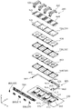
- FIG. 3 is an exploded perspective view showing each component of the power storage unit according to the embodiment.
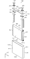
- FIG. 4 is an exploded perspective view showing each component by disassembling the electric storage element according to the embodiment.
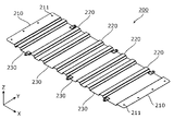
- FIG. 5A is a perspective view showing the configuration of a first plate member according to the embodiment
- 5B is a perspective view showing the configuration of the first plate member according to the embodiment;
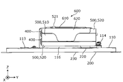
- FIG. FIG. 6 is a side view showing the positional relationship between the exterior body (the first exterior body, the second exterior body, the fixing member, and the second plate member) and the first plate member according to the embodiment.
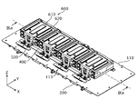
- FIG. 7 is a perspective view showing the positional relationship between the first exterior body, the storage element, the spacer, the restraining body, and the first plate member according to the embodiment.
- FIG. 8 is a side view showing the positional relationship between the storage element, the spacer, the restraining body, and the first plate member according to the embodiment.
- FIG. 9 is a cross-sectional view showing the positional relationship between the power storage element, the spacer, the restraining body, and the first plate member according to the embodiment.
- the container for the power storage element has a container body and a container lid, and electrode terminals, gas discharge valves, or the like are arranged in the container lid, whereby the container
- the crush resistance from the lid side (the crush resistance in the direction in which the container body and the container lid are arranged) is weak.
- the exterior body that houses the energy storage element plays a role of protecting the energy storage element against impact or the like in the direction in which the container main body and the container lid are arranged.
- the restraining plate is arranged above the power storage element (battery). On the other hand, it is configured to reinforce the exterior body (housing). As described above, in the above-described conventional power storage device, the resistance to crushing in the direction in which the container body and the container lid of the power storage device are arranged is relatively weak, and there is a risk that the power storage device cannot be effectively protected against external shocks and the like.
- the present invention has been made by the inventor of the present application with a new focus on the above problem, and an object of the present invention is to provide a power storage device capable of improving the protection of the power storage element against external shocks and the like.
- a power storage device includes a power storage element having a container, an exterior body in which the power storage element is housed, and arranged along the power storage element in a first direction and along the exterior body. and a plate-shaped member, wherein the container has a container body and a container lid that are joined to each other, and the container body and the container lid are arranged side by side in a second direction that intersects with the first direction.
- the plate-like member has a plate-like member convex portion that protrudes in the first direction and extends toward the edge of the plate-like member in the second direction.
- the power storage device includes the power storage element and the plate-shaped member along the exterior body in the first direction
- the container for the power storage element has the container main body and the container lid aligned in the second direction, and has a plate-like shape.
- the member protrudes in the first direction and has a plate-like member convex portion extending toward the edge of the plate-like member in the second direction.
- the plate-shaped member is arranged along the exterior body, and the plate-shaped member convex portion extending in the second direction (the direction in which the container body and the container lid of the storage element are arranged) is formed on the plate-shaped member. Therefore, the strength of the exterior body in the second direction can be reinforced by the plate member. As a result, it is possible to improve the resistance to breakdown performance in the second direction of the power storage device (the direction in which the container body and the container cover of the power storage device are arranged), thereby improving the protection of the power storage device against external shocks and the like.
- the plate-shaped member may have a plate-shaped member convex portion extending from one end edge to the other end edge of the plate-shaped member in the second direction.
- the power storage device has the plate-shaped member convex portion that protrudes in the first direction and extends across both edges in the second direction.
- the resistance to breakdown performance of the power storage device in the second direction can be improved at both edges of the plate-shaped member, so that the protection of the power storage element against impacts from the outside can be improved more reliably.
- the power storage device includes a plurality of power storage elements arranged in a longitudinal direction of the container lid in a third direction that intersects the first direction and the second direction, and the plate-like member It may have a plurality of plate-shaped member convex portions arranged in a direction.
- the power storage device includes a plurality of power storage elements aligned in the third direction, and the plate member has a plurality of plate member protrusions aligned in the third direction.
- the plate-shaped member has the plurality of plate-shaped member protrusions arranged in the third direction, so that the plurality of power storage elements are arranged in the third direction.
- the breakdown resistance performance in the second direction can be improved. As a result, it is possible to improve the protection against external shocks and the like for the plurality of power storage elements.
- the plate member may be attached to the outer surface of the exterior body.
- the plate-like member by attaching the plate-like member to the outer surface of the exterior body of the power storage device, the plate-like member can effectively protect the exterior body against impact from the outside. As a result, it is possible to more reliably improve the protection of the electric storage element against external shocks and the like.
- the plate-shaped member may be arranged in contact with the exterior body, and a space may be formed between the plate-shaped member convex portion and the exterior body.
- the plate-shaped member since the plate-shaped member is arranged in contact with the exterior body, the plate-shaped member can further reinforce the exterior body, so that the protection of the electric storage element against external impacts or the like can be more reliably improved. .
- weight reduction can be achieved, members such as bolts can be accommodated in the space, and heat can be insulated in the space.
- the exterior body has an exterior body projection projecting toward the power storage element, and the projection of the plate-shaped member projection toward the energy storage element corresponds to the exterior of the exterior body. It may be placed in contact with the perimeter of the body projection.
- the exterior body has the exterior body convex portion, the exterior body can be reinforced, so that the protection of the electric storage element against impacts from the outside can be improved more reliably.
- the convex portion of the exterior body protrudes toward the electric storage element, it is possible to suppress the expansion of the electric storage element due to the convex portion of the exterior body pressing the electric storage element.
- the protrusions of the plate-shaped member protrusions that protrude toward the electric storage element come into contact with the periphery of the exterior body protrusions. By restricting the movement of the portion, it is possible to further suppress swelling of the electric storage element.
- the present invention can be realized not only as a power storage device, but also as a combination of an exterior body and a plate-like member, or as a plate-like member.
- the longitudinal direction of the exterior body of the power storage device, the arrangement direction of a plurality of power storage elements such as the first power storage element and the second power storage element, the alignment direction of the power storage unit and the control unit, and the container of the power storage device , or the direction in which a pair of electrode terminals are arranged in one storage element is defined as the X-axis direction.
- the direction in which the electric storage elements and the busbars are arranged, or the direction in which the main body and lid of the container for the electric storage elements are arranged is defined as the Y-axis direction.
- the stacking direction or vertical direction is defined as the Z-axis direction.
- These X-axis direction, Y-axis direction, and Z-axis direction are directions that cross each other (perpendicularly in this embodiment).
- the Z-axis direction may not be the vertical direction, but for convenience of explanation, the Z-axis direction will be described below as the vertical direction.
- the positive direction of the X-axis indicates the direction of the arrow on the X-axis
- the negative direction of the X-axis indicates the direction opposite to the positive direction of the X-axis.
- the Z-axis direction may also be referred to as the first direction
- the Y-axis direction may also be referred to as the second direction
- the X-axis direction may also be referred to as the third direction.
- expressions indicating relative directions or orientations such as parallel and orthogonal include cases where they are not strictly the directions or orientations. Two directions are orthogonal, not only means that the two directions are completely orthogonal, but also substantially orthogonal, i.e., including a difference of about several percent also means
- the expression "insulation” means "electrical insulation".
- FIG. 1 is a perspective view showing the appearance of a power storage device 1 according to this embodiment.
- FIG. 2 and FIG. 3 are exploded perspective views showing respective constituent elements of power storage unit 10 according to the present embodiment.
- FIG. 3 shows an exploded view of each component fixed to first exterior body 110 of power storage unit 10 shown in FIG. 2 .
- the power storage device 1 is a device that can charge electricity from the outside and discharge electricity to the outside, and has a substantially rectangular parallelepiped shape in the present embodiment.
- the power storage device 1 is a battery module (assembled battery) used for power storage, power supply, or the like.
- the power storage device 1 is used for driving mobile bodies such as automobiles, motorcycles, water crafts, ships, snowmobiles, agricultural machinery, construction machinery, or railway vehicles for electric railways, or for starting engines. Used as a battery or the like. Examples of such vehicles include electric vehicles (EV), hybrid electric vehicles (HEV), plug-in hybrid electric vehicles (PHEV), and fossil fuel (gasoline, light oil, liquefied natural gas) vehicles. Examples of railway vehicles for the electric railway include electric trains, monorails, linear motor cars, and hybrid trains having both diesel engines and electric motors.
- the power storage device 1 can also be used as a stationary battery or the like for home or business use.
- the power storage device 1 includes a power storage unit 10 and a control unit 20.
- the portion of the power storage device 1 that has the power storage element 400 is referred to as power storage unit 10
- the portion that includes a control device for controlling power storage element 400 is referred to as control unit 20 .
- the power storage unit 10 has an exterior body 100 and a first plate-shaped member 200. Inside the exterior body 100, an energy storage element 400, a spacer 500, a restraint body 600, a busbar frame 700, a busbar 800, and a conductive member. 900, the control unit 20 and the like are accommodated.
- a pair of (positive and negative) external terminals 21 and 22 and a connector 23 are arranged on the exterior body 100 . Each component will be described in detail below.
- the exterior body 100 is a box-shaped (substantially rectangular parallelepiped) container (module case) that constitutes the exterior body of the power storage device 1 .
- the exterior body 100 is arranged outside the power storage elements 400 and the like, fixes the power storage elements 400 and the like at predetermined positions, and protects them from impacts and the like.
- the exterior body 100 has a first exterior body 110 , a second exterior body 120 , a fixing member 130 , a gasket 140 and a second plate member 300 .
- the first exterior body 110 is a flat rectangular member that constitutes the main body of the exterior body 100, on which the power storage element 400 and the like are placed and fixed.
- the second exterior body 120 is a bottomed rectangular cylindrical member that constitutes the lid of the exterior body 100, is arranged in the positive Z-axis direction of the first exterior body 110, and is connected to the first exterior body 110. cover the power storage element 400 and the like.
- An opening is formed in the second exterior body 120 in the negative direction of the Z axis, and the first exterior body 110 is arranged so as to block the opening of the second exterior body 120 .
- the first exterior body 110 is made of a metal member such as stainless steel, aluminum, aluminum alloy, iron, steel plate, or the like, or the metal that has been subjected to insulation treatment such as insulation coating, from the viewpoint of ensuring safety (breakage resistance). It is formed of a highly rigid member such as a member.
- the second exterior body 120 is made of polycarbonate (PC), polypropylene (PP), polyethylene (PE), polystyrene (PS), polyphenylene sulfide resin (PPS), polyphenylene ether (PPE (including modified PPE), )), polyethylene terephthalate (PET), polybutylene terephthalate (PBT), polyether ether ketone (PEEK), tetrafluoroethylene/perfluoroalkyl vinyl ether (PFA), polytetrafluoroethylene (PTFE), polyether sulfone ( PES), polyamide (PA), ABS resin, or a resin member (insulating member) such as a composite material thereof.
- the first exterior body 110 may be formed of the same resin member as the second exterior body 120, it is preferably formed of a highly rigid member.
- the second exterior body 120 may be formed of the same metal member as the first exterior body 110 .
- the first exterior body 110 has a first connection portion 111 , mounting bases 113 , 114 and 115 , and an exterior body convex portion 116 .
- the second exterior body 120 has a second connection portion 121 .
- the first connection portion 111 is a portion (flange portion) that is arranged on the outer peripheral portion of the first exterior body 110 and has an angular annular shape (as viewed from the Z-axis direction) in a top view (flange portion). It is arranged at a position facing the connecting portion 121 , overlapped with the second connecting portion 121 and connected to the second connecting portion 121 .
- the second connection portion 121 is a rectangular ring-shaped portion (flange portion) in a top view that is arranged on the outer peripheral portion of the second exterior body 120, and is arranged at a position facing the first connection portion 111. It is superimposed on the one connection portion 111 and connected to the first connection portion 111 .
- the first connection portion 111 and the second connection portion 121 are connection portions that are overlapped and connected to each other in the Z-axis direction (first direction), and are connected in the Y-axis direction (second direction intersecting the first direction) and They are arranged along the X-axis direction (the third direction intersecting the first direction and the second direction).
- the mounting bases 113 and 114 are members to which the restraining body 600 is attached. Specifically, the mounting base 113 is arranged at the end of the first exterior body 110 in the negative Y-axis direction, and is attached to a portion of the restraining body 600 on the negative Y-axis direction side of the first restraining body 610 described later. The mounting base 114 is arranged at the end of the first exterior body 110 in the positive Y-axis direction, and the portion of the first restricting body 610 on the positive Y-axis direction side is attached thereto. More specifically, mounting bases 113 and 114 have bolt portions, and the bolt portions are coupled with nuts to attach restraining body 600 (first restraining body 610) to mounting bases 113 and 114. be done.
- the mounting base 115 is a member to which the conductive member 900 is attached. Specifically, the mounting base 115 is arranged at the center in the X-axis direction and the end in the positive Y-axis direction of the first exterior body 110, and mounting portions 913 and 923, which will be described later, of the conductive member 900 are mounted thereon. More specifically, mounting base 115 has a bolt portion, and conductive member 900 (mounting portions 913 and 923) is attached to mounting base 115 by coupling the bolt portion with a nut.
- the exterior body convex portion 116 is a convex portion that protrudes toward the power storage element 400 .
- the exterior body convex portion 116 is a projection portion that is disposed in the Y-axis direction center portion of the first exterior body 110, has a rectangular shape in a top view, and protrudes in the Z-axis positive direction.
- Four exterior body protrusions 116 are arranged side by side in the X-axis direction corresponding to the four power storage elements 400 aligned in the X-axis direction.
- Each of the exterior body protrusions 116 is arranged at a position facing the central portion of the later-described long side surface 411a of the electric storage element 400, and presses the central portion of the electric storage element 400 (see FIG. 9).
- a control wire (also referred to as a communication line, control line, communication cable, or control cable) that transmits information such as the voltage or temperature of the storage element 400 is connected to the control unit 20 in the second exterior body 120 .
- information such as the voltage or temperature of the storage element 400 is transmitted to and from the control unit 20 .
- the control unit 20 is electrically connected to the connector 23, thereby transmitting the information to the outside.
- the gasket 140 is a gasket arranged between the first exterior body 110 and the second exterior body 120 .
- the gasket 140 is an O-ring that is arranged between the first connection portion 111 and the second connection portion 121 and has a rectangular ring shape when viewed from above. More specifically, the gasket 140 is arranged between the first connecting portion 111 and the second connecting portion 121 in a state of being compressed to the first connecting portion 111 and the second connecting portion 121 .
- the gasket 140 is made of any resin material such as rubber (natural rubber, synthetic rubber), PC, PP, PE, etc. that can be used for the second exterior body 120 .
- the second plate member 300 is a member arranged at a position sandwiching the second exterior body 120 with the first exterior body 110 and arranged along the outer peripheral portions of the first exterior body 110 and the second exterior body 120. .
- the second plate member 300 is arranged at a position sandwiching the second connection portion 121 with the first connection portion 111, and extends in the X-axis direction or the Y-axis direction (the third direction or the second direction).
- two second plate members 301 extending in the X-axis direction (third direction) are arranged for the first connection portion 111 and the second connection portion 121 on both sides in the Y-axis direction.
- Two second plate members 302 extending in the Y-axis direction (second direction) are arranged with respect to the first connection portion 111 and the second connection portion 121 on both sides in the X-axis direction.
- the four second plate-shaped members 300 cover substantially the entire outer peripheral portions of the first exterior body 110 and the second exterior body 120. placed across.
- the second plate member 300 is arranged to extend over the plurality of fixing members 130 .
- the second plate-shaped member 300 is formed of a highly rigid member such as a metal member such as stainless steel, aluminum, aluminum alloy, iron, steel plate, or the like, or the metal member subjected to insulation treatment such as insulating coating.
- the first connection portion 111 is a metal (high rigidity) flange portion
- the second connection portion 121 is a resin (low rigidity) flange portion. Therefore, the second connection portion 121 has lower rigidity than at least one of the first connection portion 111 and the second plate member 300 .
- second connection portion 121 has lower rigidity than both first connection portion 111 and second plate member 300 .
- At least one of first connection portion 111 and second plate member 300 (both first connection portion 111 and second plate member 300 in the present embodiment) has higher rigidity than second connection portion 121 .
- High (or low) rigidity means strong (or weak) against external forces, and can be defined as a state in which dimensional change is small (or large) against bending and torsional forces. That the second connection portion 121 has lower rigidity than the first connection portion 111 means that when the central portions of the regions of the same size of the first connection portion 111 and the second connection portion 121 are pressed with the same force, the second connection portion 121 This refers to the case where the connection portion 121 has a larger dimensional change (amount of deflection). It can also be said that the second connection portion 121 requires less force than the first connection portion 111 to cause the same dimensional change.
- the definition of rigidity is not limited to the above, and may be defined within a range that can be normally interpreted by those skilled in the art.
- the second connection portion 121 may have lower rigidity as a whole than at least one of the first connection portion 111 and the second plate member 300 .
- the second connection portion 121 may have lower material rigidity than at least one of the first connection portion 111 and the second plate-shaped member 300 (may be formed of a material having lower rigidity), or may be structurally less rigid. It may have low rigidity (it may be configured in a shape with low rigidity).
- the fixing member 130 has a first fixing member 131 and a second fixing member 132 .
- the first fixing member 131 and the second fixing member 132 are members that are connected (joined) to each other to connect (join) the first exterior body 110 and the second exterior body 120 .
- a plurality of second fixing members 132 are arranged side by side at substantially equal intervals in the first connection portion 111
- a plurality of first fixing members 132 are arranged in positions corresponding to the second fixing members 132 of the second connection portion 121 .
- the fixing members 131 are arranged side by side. Thereby, the first fixing member 131 and the second fixing member 132 connect (bond) the first connecting portion 111 and the second connecting portion 121 together with the second plate member 300 .
- the first fixing member 131 is a bolt
- the second fixing member 132 is a nut to which the bolt is coupled.
- a through hole 111 a is formed in the first connecting portion 111
- a through hole 121 a is formed in the second connecting portion 121
- a through hole 311 is formed in the second plate member 300 .
- the male threaded portion of the first fixing member 131 is inserted into the through holes 311 , 121 a and 111 a and coupled to the female threaded portion of the second fixing member 132 .
- the first fixing member 131 and the second fixing member 132 move toward the second connecting portion 121 with the second connecting portion 121 sandwiched between the first connecting portion 111 and the second plate-like member 300 .
- the plate member 300 is pressed to connect (fix) the first connection portion 111 and the second connection portion 121 .
- the second fixing member 132 may be a bolt, and the first fixing member 131 may be a nut to which the bolt is coupled.
- the method of connecting (bonding) the first exterior body 110 and the second exterior body 120 may be other methods such as bonding with rivets, caulking, sandwiching with clips, adhesion, welding, heat sealing, ultrasonic welding, and the like. There may be.
- the first plate-shaped member 200 is a plate-shaped member arranged along the exterior body 100 and aligned with the power storage element 400 in the Z-axis direction (first direction).
- the first plate member 200 is attached to the outer surface of the exterior body 100 .
- the first plate-shaped member 200 is a rectangular and corrugated plate-shaped member that extends in the X-axis direction along the first exterior body 110 in the negative Z-axis direction of the storage element 400 and the first exterior body 110. is.
- the first plate member 200 is in contact with and attached to the outer surface of the first exterior body 110 on the negative Z-axis direction side.
- the first plate member 200 may be formed by bending a plate member into a corrugated plate shape, or may be formed by casting (die casting) or the like.
- the first plate-shaped member 200 is fixed at both ends in the X-axis direction by the fixing members 130 (the first fixing member 131 and the second fixing member 132). Together with 300, it is attached to the first connection portion 111 (see FIG. 6).
- the first plate-like member 200 has plate-like member connecting portions 210 in which through holes 211 are formed at both ends in the X-axis direction. Through hole 311 of second plate member 300 , through hole 121 a of second connecting portion 121 , through hole 111 a of first connecting portion 111 , and through hole 211 of plate member connecting portion 210 , male of first fixing member 131 is inserted.
- the threaded portion is inserted and the male threaded portion is coupled with the female threaded portion of the second fixing member 132 .
- the first plate-shaped member 200 is attached to the first exterior body 110 together with the second exterior body 120 and the second plate-shaped member 300 .
- the second plate members 300 are not arranged at positions corresponding to the fixing members 130 arranged at both ends in the X-axis direction and both ends in the Y-axis direction (corners in the X-axis direction and the Y-axis direction). Therefore, the first plate member 200 is attached to the first connection portion 111 together with the second connection portion 121 at the corner portion. At the corners, the first plate member 200 is attached to the first exterior body 110 together with the second exterior body 120 . A detailed description of the configuration of the first plate member 200 will be given later.
- the storage element 400 is a secondary battery (single battery) capable of charging and discharging electricity, and more specifically, a non-aqueous electrolyte secondary battery such as a lithium ion secondary battery.
- the power storage elements 400 have a flattened rectangular parallelepiped shape (rectangular shape). 411a faces the Z-axis direction), and are arranged in the Z-axis direction and the X-axis direction. Specifically, two first power storage elements 401 are stacked (flat stacked) in the Z-axis direction, two second power storage elements 402 are stacked (flat stacked) in the Z-axis direction, and two third power storage elements 403 are stacked (flat stacked).
- the two first storage elements 401, the two second storage elements 402, the two third storage elements 403, and the two fourth storage elements 404 move from the negative direction of the X axis to the positive direction of the X axis, They are arranged side by side in the X-axis direction.
- the number of power storage elements 400 is not particularly limited, and any number of power storage elements 400 may be arranged (stacked) in the Z-axis direction, and how many power storage elements 400 may be arranged (arranged) in the X-axis direction.
- the shape of the electric storage element 400 is not limited to the rectangular shape described above, and may be other shapes such as a polygonal columnar shape, a cylindrical shape, an elliptical columnar shape, and an oval columnar shape.
- the storage element 400 is not limited to a non-aqueous electrolyte secondary battery, and may be a secondary battery other than a non-aqueous electrolyte secondary battery, or may be a capacitor.
- the power storage element 400 may be a primary battery that can use stored electricity without being charged by the user, instead of a secondary battery.
- Electric storage element 400 may be a battery using a solid electrolyte.
- the storage element 400 may be a pouch-type storage element. A detailed description of the configuration of the storage element 400 will be given later.
- the spacer 500 is a rectangular and plate-like spacer arranged adjacent to the power storage element 400 .
- Spacer 500 is arranged in the Z-axis plus direction or the Z-axis minus direction of storage element 400 , facing long side surface 411 a of storage element 400 .
- the spacer 500 is formed of an insulating member such as any resin material that can be used for the second exterior body 120, or a member having a high heat insulating property such as a damper material.
- an intermediate spacer 510 and a pair of end spacers 520 are arranged as spacers 500 .
- the intermediate spacer 510 is the spacer 500 arranged between the two power storage elements 400
- the end spacer 520 is the spacer 500 arranged between the power storage element 400 and the first exterior body 110 or the restraining body 600.
- An intermediate spacer 510 and a pair of end spacers 520 are arranged so as to sandwich the power storage element 400 in the Z-axis direction, and between the power storage elements 400 and between the power storage elements 400 and the first exterior body 110 and the restraining body 600.
- the intermediate spacer 510 is provided for each of the first power storage element 401 to the fourth power storage element 404. and a pair of end spacers 520 are arranged.
- an insulating sheet may be arranged on the side surface of power storage element 400.
- Each of the end spacers 520 arranged on the positive side of the Z-axis has two protrusions 521 aligned in the X-axis direction at the ends in the negative Y-axis direction.
- the protrusion 521 is inserted into a circular through-hole 611 formed in a first restraining body 610 and a circular through-hole 621 formed in a second restraining body 620 of a restraining body 600 described later in the Z-axis plus direction. It is a columnar protrusion protruding into the Thereby, the restraining body 600 can be positioned with respect to the spacer 500 (and the storage element 400).
- the restraint body 600 is a member that sandwiches a plurality of power storage elements 400 such as the first power storage element 401 and the second power storage element 402 together with the first exterior body 110 in the Z-axis direction. Specifically, first exterior body 110 and restraint body 600 are joined together to sandwich a plurality of power storage elements 400 . Thereby, the first exterior body 110 and the restraining body 600 restrain the plurality of power storage elements 400 in the Z-axis direction (apply a restraining force in the Z-axis direction to the plurality of power storage elements 400). First exterior body 110 extends in the X-axis direction across first to fourth storage elements 401 to 404, and restraint body 600 holds first to fourth storage elements 401 to 404 respectively. Individually constrained with the single exterior body 110 .
- the restraint body 600 is formed of a metal member or the like that can be used for the first exterior body 110 .
- the restraining body 600 has a first restraining body 610 and a second restraining body 620.
- the first restraint body 610 is a plate-like member arranged in the positive Z-axis direction of the second restraint body 620 and joined to the first exterior body 110 and having an inverted U shape when viewed from the X-axis direction.
- the second restraint body 620 is a plate-like member arranged so as to cover substantially the entire side surface of the power storage element 400 and the spacer 500 (end spacer 520) in the positive Z-axis direction.
- the first restraint body 610 and the second restraint body 620 are formed with projections extending in the Y-axis direction for strength improvement, etc., but the position, shape and number of the projections are not particularly limited. , a configuration in which no convex portion is formed.
- the first restraint 610 and the second restraint 620 may be integrally formed, or the restraint 600 may not have the second restraint 620 .
- the first storage element 401 to the fourth storage element 404 are arranged apart from each other, and the restraining bodies 600 arranged in the X-axis direction are also arranged apart from each other. Therefore, heat transfer between the first storage element 401 and the second storage element 402 can be suppressed, so that the first storage element 401 and the second storage element 402 can be prevented from exerting thermal influence on each other.
- a heat insulating material may be placed in the gap between the first storage element 401 and the second storage element 402 to further suppress the thermal influence of the first storage element 401 and the second storage element 402 on each other.
- the busbar frame 700 is a flat rectangular insulating member capable of electrically insulating the busbar 800 from other members and regulating the position of the busbar 800 .
- the busbar frame 700 is made of any resin material or the like that can be used for the second exterior body 120 .
- the busbar frame 700 is arranged in the Y-axis negative direction of the plurality of power storage elements 400 and is positioned with respect to the plurality of power storage elements 400 , so that the busbar 800 is positioned with respect to the plurality of power storage elements 400 . It is joined to the electrode terminals of the plurality of power storage elements 400 .
- the bus bar 800 is a plate-like member that is arranged in the Y-axis negative direction of the plurality of storage elements 400 and is connected (joined) to the plurality of storage elements 400 and the conductive member 900 .
- Busbar 800 includes busbars 810 , 820 and 830 .
- Bus bar 810 connects electrode terminals 420 (to be described later) of adjacent storage elements 400 to each other.
- the bus bars 820 and 830 connect the electrode terminals 420 of the storage element 400 to the later-described connection portions 912 and 922 of the conductive member 900, thereby electrically connecting the storage element 400 to the positive and negative external terminals 21 and 22. do.
- bus bar 800 and electrode terminal 420 of power storage element 400 are connected (joined) by welding, but may be connected (joined) by bolting or the like.
- Bus bar 800 and connecting portions 912 and 922 of conductive member 900 are connected (joined) by bolting, but may be connected (joined) by welding or the like.
- Bus bar 800 is made of a conductive member made of metal such as aluminum, aluminum alloy, copper, copper alloy, nickel, or a combination thereof, or a conductive member other than metal.
- the bus bar 800 connects two power storage elements 400 in parallel to form four sets of power storage element groups, and connects the four power storage element groups in series. All eight power storage elements 400 may be connected in series, or other configurations may be used.
- the conductive member 900 is a conductive member that is connected to the bus bar 800 and the control unit 20 to electrically connect the power storage element 400 and the external terminals 21 and 22 . That is, the conductive member 900 is a conductive member (also referred to as a power line, power line, main circuit cable, power cable, or power cable) arranged on the main current (charge/discharge current) path of the storage element 400 .
- the conductive member 900 is made of a conductive member made of metal such as aluminum, an aluminum alloy, copper, a copper alloy, or nickel, a combination thereof, or a conductive member other than metal.
- the conductive member 900 has a conductive member 910 and a conductive member 920 .
- the conductive member 910 has connecting portions 911 and 912 and a mounting portion 913 .
- the conductive member 920 has connecting portions 921 and 922 and a mounting portion 923 .
- connection portion 912 is a portion connected to the busbar 820
- connection portion 922 is a portion connected to the busbar 830
- the attachment portions 913 and 923 are portions attached to the attachment base 115 of the first exterior body 110 .
- the conductive member 910 has a configuration in which a plate member extends from the connection portion 911 to the attachment portion 913 and an electric wire extends from the attachment portion 913 to the connection portion 912. have.
- the conductive member 920 has a configuration in which a plate member extends from the connection portion 921 to the attachment portion 923 and an electric wire extends from the attachment portion 923 to the connection portion 922 .
- the control unit 20 is a device having a control device (not shown) that controls the storage elements 400 in the storage unit 10 , specifically a BMS (Battery Management System) that controls the storage elements 400 .
- the control device arranged in the control unit 20 is a device that is connected to the main current path of the storage element 400 and controls the storage element 400, and includes a circuit board, fuse, relay, Semiconductor switches such as FETs (Field Effect Transistors), shunt resistors, and the like.
- the control unit 20 is housed in the exterior body 100 .
- External terminals 21 and 22 which are a pair of positive and negative module terminals (general terminals), are arranged at the ends of the exterior body 100 in the positive direction of the X axis. External terminals 21 and 22 are electrically connected to power storage element 400 of power storage unit 10 via connecting portions 911 and 921 .
- the power storage device 1 charges electricity from the outside and discharges electricity to the outside through the external terminals 21 and 22 .
- the external terminal 21 is a positive external terminal that is a positive external terminal
- the external terminal 22 is a negative external terminal that is a negative external terminal.
- the external terminals 21 and 22 are made of a metal conductive member such as aluminum, aluminum alloy, copper, copper alloy, or the like.
- the configuration of power storage element 400 will be described in detail.
- the eight power storage elements 400 (two first power storage elements 401, two second power storage elements 402, two third power storage elements 403, and two fourth power storage elements 404) provided in the power storage unit 10 are all the same. , the configuration of one power storage element 400 will be described below.
- FIG. 4 is an exploded perspective view showing each component by disassembling the power storage element 400 according to the present embodiment. Specifically, FIG. 4 shows an exploded view of each part in a state in which the power storage element 400 shown in FIG. 3 is placed vertically (upright).
- the electric storage element 400 includes a container 410, a pair of (positive electrode and negative electrode) electrode terminals 420, and a pair of (positive electrode and negative electrode) gaskets 430.
- a pair of (positive electrode and negative electrode) gaskets 440 , a pair (positive electrode and negative electrode) current collectors 450 , and an electrode body 460 are housed inside the container 410 .
- An electrolytic solution non-aqueous electrolyte
- the type is not particularly limited as long as it does not impair the performance of the electric storage element 400, and various kinds can be selected.
- spacers disposed on the side surface or bottom surface of the electrode body 460, an insulating film that wraps the electrode body 460 and the like, an insulating sheet that covers the outer surface of the container 410, and the like may be disposed.
- the container 410 is a rectangular parallelepiped (square or box-shaped) case having a container body 411 with an opening and a container lid 412 closing the opening of the container body 411 .
- the container 410 has a structure that can seal the inside by welding the container main body 411 and the container lid 412 after the electrode body 460 and the like are accommodated inside the container main body 411 .
- the material of the container body 411 and the container lid 412 is not particularly limited, but weldable metals such as stainless steel, aluminum, aluminum alloys, iron, and plated steel plates are preferable.
- the container main body 411 is a rectangular tubular member that constitutes the main body of the container 410 and has a bottom, and an opening is formed on the Y-axis negative direction side.
- the container body 411 has a pair of rectangular and planar (flat) long side surfaces 411a on both side surfaces in the Z-axis direction, and a pair of rectangular and planar (flat) side surfaces on both side surfaces in the X-axis direction. It has a short side surface 411b and a rectangular planar (flat) bottom surface 411c on the Y-axis plus direction side.
- the container lid 412 is a rectangular plate-like member that constitutes the lid of the container 410 , and is arranged on the Y-axis minus direction side of the container body 411 so as to extend in the X-axis direction.
- the container cover 412 has a gas discharge valve 412a that releases the pressure inside the container 410 when the pressure rises, and an injection part (not shown) for injecting the electrolytic solution into the container 410. ) etc. are provided.
- the container 410 has a container body 411 and a container lid 412 that are arranged side by side in the Y-axis direction (second direction) and joined together.
- the first storage element 401 to the fourth storage element 404 are arranged side by side in the X-axis direction (third direction), which is the longitudinal direction of the container lid 412 .
- the electrode body 460 is a power storage element (power generation element) formed by laminating a positive electrode plate, a negative electrode plate, and a separator.
- the positive electrode plate is formed by forming a positive electrode active material layer on a positive electrode substrate layer, which is a collector foil made of a metal such as aluminum or an aluminum alloy.
- the negative electrode plate is formed by forming a negative electrode active material layer on a negative electrode substrate layer, which is a collector foil made of a metal such as copper or a copper alloy.
- the active material used for the positive electrode active material layer and the negative electrode active material layer any known material can be appropriately used as long as it can intercalate and deintercalate lithium ions.
- electrode body 460 is formed by winding electrode plates (positive electrode plate and negative electrode plate) around a winding axis (virtual axis parallel to the X-axis direction) extending in the X-axis direction. It is a type (so-called vertically wound type) electrode body.
- Electrode body 460 is formed by stacking electrode plates in the stacking direction.
- the electrode body 460 has a pair of flat portions 461 aligned in the Z-axis direction and a pair of curved portions 462 aligned in the Y-axis direction by winding the electrode plate. is the stacking direction of the electrode plates in the flat portion 461 .
- the flat portion 461 is a flat portion that connects the ends of a pair of curved portions 462, and the curved portion 462 is a portion curved in a semicircular shape or the like so as to protrude in the Y-axis direction.
- the direction in which the flat surface of the flat portion 461 faces or the facing direction of the pair of flat portions 461 can also be defined as the stacking direction. Therefore, it can be said that the plurality of first power storage elements 401 are arranged in the stacking direction.
- the X-axis direction in which the first storage element 401 to the fourth storage element 404 are arranged is also called the arrangement direction.
- the first storage element 401 to the fourth storage element 404 are arranged in the arrangement direction crossing the stacking direction.
- the active material is formed (coated) at the ends of the positive electrode plate and the negative electrode plate in the shifted direction. 3) It has a part (active material layer non-formed part) where the base material layer is exposed without being exposed.
- the electrode body 460 protrudes from the flat portion 461 and the curved portion 462 to both sides in the X-axis direction at both ends in the X-axis direction, and the active material layer non-formed portions of the positive electrode plate and the negative electrode plate are laminated to form the current collector 450 . It has an end 463 connected to the .
- the electrode body 460 includes a so-called horizontally wound electrode body formed by winding electrode plates around a winding axis extending in the Y-axis direction, and a laminated type (
- the electrode body may be of any form, such as a stack type electrode body, a bellows-shaped electrode body in which electrode plates are folded into a bellows shape, or the like.
- the flat portion is the flat portion other than the curved portion and the connection portion (tab) with the current collector.
- a flat portion is a flat portion other than the connection portion (tab) with the current collector.
- the electrode terminals 420 are terminals (a positive terminal and a negative terminal) of the power storage element 400, and are arranged on the container lid 412 so as to protrude in the negative direction of the Y axis.
- the electrode terminal 420 is electrically connected to the positive plate and the negative plate of the electrode body 460 via the current collector 450 .
- the electrode terminal 420 is made of a conductive member such as metal such as aluminum, aluminum alloy, copper, copper alloy, or the like.
- the current collector 450 is a conductive member (a positive electrode current collector and a negative electrode current collector) electrically connected to the electrode terminal 420 and the end portion 463 of the electrode body 460 .
- the current collector 450 is made of aluminum, an aluminum alloy, copper, a copper alloy, or the like.
- the gaskets 430 and 440 are plate-shaped electrically insulating sealing members arranged between the container cover 412 and the electrode terminal 420 and current collector 450 .
- the gaskets 430 and 440 are made of any electrically insulating resin material or the like that can be used for the second exterior body 120 .
- FIG. 5A and 5B are perspective views showing the configuration of the first plate member 200 according to this embodiment. Specifically, FIG. 5A is an enlarged perspective view showing the first plate member 200 shown in FIG. 2, and FIG. 5B is an enlarged perspective view of the first plate member 200 shown in FIG. It is a perspective view showing the configuration when rotated by degrees.
- FIG. 6 shows the positional relationship between the exterior body 100 (the first exterior body 110, the second exterior body 120, the fixing member 130, and the second plate-shaped member 300) and the first plate-shaped member 200 according to the present embodiment. is a side view showing. Specifically, (a) of FIG. 6 shows the configuration of the power storage device 1 shown in FIG. 1 when viewed from the Y-axis negative direction, and (b) of FIG. The part surrounded by the dashed line is enlarged.
- FIG. 7 is a perspective view showing the positional relationship between first exterior body 110, power storage element 400, spacer 500, restraint body 600, and first plate member 200 according to the present embodiment. Specifically, FIG. shows the configuration when .
- FIG. 8 is a side view showing the positional relationship between power storage element 400, spacer 500, restraint body 600, and first plate member 200 according to the present embodiment. Specifically, FIG. 8 shows the configuration when the configuration of FIG. 7 is viewed from the positive direction of the X-axis.
- FIG. 9 is a cross-sectional view showing the positional relationship between power storage element 400, spacer 500, restraint body 600, and first plate member 200 according to the present embodiment. Specifically, (a) of FIG. 9 shows a cross section of the configuration of FIG. 7 taken along the line IXa-IXa and parallel to the XZ plane, and 4A is an enlarged view of the portion enclosed by the dashed line in (a) of FIG.
- the first plate-like member 200 has plate-like member convex portions 220 and 230 in addition to the plate-like member connecting portion 210 .
- the plate-like member connection portions 210 are rectangular plate-like portions that extend in the Y-axis direction and are arranged at both ends of the first plate-like member 200 in the X-axis direction. In the form, four through holes 211 are formed.
- the plate-like member protrusions 220 and 230 are arranged between the two plate-like member connecting portions 210, protrude in the Z-axis direction (first direction), and form the first plate-like shape in the Y-axis direction (second direction). It is an elongated projection (projection) extending from one end edge of the member 200 to the other end edge.
- the plate-like member convex portion 220 is a convex portion that protrudes in the positive Z-axis direction and extends linearly in the Y-axis direction across both edges of the first plate-like member 200 in the Y-axis direction.
- the plate-like member convex portion 230 is a convex portion that protrudes in the negative Z-axis direction and linearly extends in the Y-axis direction across both edges of the first plate-like member 200 in the Y-axis direction.
- the plate-shaped member convex portion 220 is recessed in the Z-axis positive direction on the surface of the first plate-shaped member 200 on the negative Z-axis direction, and is located on the positive Z-axis direction side of the first plate-shaped member 200.
- the surface is a convex portion that protrudes in the positive direction of the Z axis.
- the plate-shaped member convex portion 230 has a surface on the Z-axis positive direction side of the first plate-shaped member 200 that is recessed in the Z-axis negative direction, and a surface on the Z-axis negative direction side of the first plate-shaped member 200 that is recessed in the Z-axis negative direction. It is a projection projecting in the direction.
- a plurality of plate member convex portions 220 and 230 are arranged side by side in the X-axis direction (third direction).
- the plurality of plate-shaped member convex portions 220 and 230 are alternately arranged in the X-axis direction over the plurality of power storage elements 400 (first power storage element 401 to fourth power storage element 404) (Fig. 7 and FIG. 9).
- the first plate member 200 has a shape like a corrugated plate.
- the first plate member 200 has the same length as the exterior body 100 (first exterior body 110) in the X-axis direction and the Y-axis direction.
- the plate member protrusions 220 and 230 have the same length as the exterior body 100 (first exterior body 110) in the Y-axis direction. Accordingly, the first plate-shaped member 200 is formed longer than the power storage element 400 in the X-axis direction and the Y-axis direction, and the plate-shaped member protrusions 220 and 230 are formed longer than the power storage element 400 in the Y-axis direction. formed.
- the first plate-shaped member 200 is arranged to protrude more than all of the power storage elements 400 on both sides in the X-axis direction and both sides in the Y-axis direction, and the plate-shaped member protrusions 220 and 230 are arranged on both sides in the Y-axis direction. is arranged to protrude from the storage element 400 of .
- the first plate member 200 may have the same length as the storage element 400 in the X-axis direction or the Y-axis direction.
- the first plate-shaped member 200 may be formed to extend at least to the edge of the storage element 400 in the X-axis direction or the Y-axis direction, and the plate-shaped member convex portions 220 and 230 are formed in the Y-axis direction to: It may be formed to extend at least to the edge of power storage element 400 .
- at least a part of the first plate-shaped member 200 may overlap the edge of the power storage element 400 in the X-axis direction or the Y-axis direction when viewed from the Z-axis direction.
- 230 may at least partially overlap the edge of the storage element 400 in the Y-axis direction when viewed from the Z-axis direction.
- the plate-shaped member protrusions 220 and 230 have a trapezoidal shape when viewed from the Y-axis direction, but when viewed from the Y-axis direction, they have a polygonal shape such as a rectangular shape, a triangular shape, or a semicircular shape. It may have any shape, such as a shape, a semi-elliptical shape, a semi-oval shape, or the like. Since one surface of the first plate member 200 is recessed, the plate member protrusions 220 and 230 can also be called recesses.
- the first plate-shaped member 200 is arranged in contact with the exterior body 100 , and a space is formed between the plate-shaped member convex portions 220 and 230 and the exterior body 100 . As shown in FIGS. 6 and 9 and the like, the first plate-shaped member 200 is arranged in contact with the first exterior body 110, and between the plate-shaped member convex portions 220 and 230 and the first exterior body 110 A space S is formed in . In the space S, the portion of the fixing member 130 protruding from the first exterior body 110 (the male screw portion of the first fixing member 131 and the second fixing member 132) and the exterior body formed on the first exterior body 110 Protrusions 117 and the like are arranged.
- the exterior body protrusion 117 is a protrusion formed on the first exterior body 110 and protruding in the Z-axis minus direction.
- the exterior body convex portion 117 is formed by recessing the surface of the first exterior body 110 on the Z-axis positive direction side. It is a convex portion that protrudes from the surface on the negative side of the axis.
- the convex portion (plate-shaped member convex portion 220 ) of the plate-shaped member convex portions 220 and 230 that protrudes toward the power storage element 400 is the outer body convex portion 116 of the outer package 100 . It is placed in contact with the surroundings.
- the plate-shaped member convex portion 220 is arranged at a position shifted from the exterior body convex portion 116 in the X-axis direction. It abuts on a portion adjacent to the portion 116 in the X-axis direction.
- the plate-shaped member convex portion 220 has a contact portion 221 arranged in contact with the periphery of the exterior body convex portion 116 .
- the abutting portions 221 are plate-like portions arranged on both sides of the convex portion 116 of the exterior body in the X-axis direction and extending in the Y-axis direction.
- the first plate-shaped member 200 presses the exterior body projection 116 of the first exterior body 110 in the Z-axis plus direction by the contact portion 221 of the plate-shaped member projection 220 .
- Exterior body convex portion 116 presses the central portion of long side surface 411 a of container 410 of power storage element 400 in the positive Z-axis direction via end spacer 520 .
- the power storage device 1 includes the power storage element 400 and the plate-shaped first plate member 200 along the exterior body 100 in the first direction (Z-axis direction).
- a container 410 of the element 400 has a container body 411 and a container lid 412 arranged in the second direction (Y-axis direction).
- the first plate-like member 200 has plate-like member convex portions 220 and 230 that protrude in the first direction and extend across both edges in the second direction.
- the first plate member 200 can reinforce the strength of the exterior body 100 in the second direction.
- the resistance to breakdown performance in the second direction (the direction in which the container main body 411 and the container lid 412 are arranged) of the power storage device 1 can be improved, so that the protection of the power storage element 400 against impacts from the outside can be improved.
- the power storage device 1 includes a plurality of power storage elements 400 arranged in the third direction (X-axis direction), and the first plate member 200 has a plurality of plate member protrusions 220 and 230 arranged in the third direction. is doing.
- the first plate-shaped member 200 has the plurality of plate-shaped member protrusions 220 and 230 arranged in the third direction.
- the breakdown voltage performance in the second direction for the plurality of storage elements 400 can be improved.
- the plurality of power storage elements 400 can be more protected against external shocks and the like.
- the first plate member 200 By attaching the first plate member 200 to the outer surface of the exterior body 100 of the power storage device 1, the first plate member 200 can effectively protect the exterior body 100 against external impact. As a result, the protection of the electric storage element 400 against external shock or the like can be improved. By attaching the first plate-shaped member 200 to the outer surface of the exterior body 100 , the first plate-shaped member 200 can radiate the heat of the storage element 400 through the exterior body 100 .
- the first plate-shaped member 200 By placing the first plate-shaped member 200 in contact with the exterior body 100, the first plate-shaped member 200 can further reinforce the exterior body 100, thereby improving the protection of the power storage element 400 against external shocks and the like. can.
- a space S between the plate-shaped member convex portions 220 and 230 and the exterior body 100 it is possible to reduce the weight or to insert a member such as a bolt (fixing member 130, exterior body convex portion 117, etc.) in the space S. It can be housed or insulated in the space S.
- the contact of the first plate member 200 with the exterior body 100 allows the first plate member 200 to radiate the heat of the power storage element 400 via the exterior body 100 .
- the exterior body 100 has the exterior body protrusions 116, the exterior body 100 can be reinforced, so that the power storage element 400 can be better protected against impacts from the outside. Since exterior body protrusion 116 protrudes toward power storage element 400 , it is possible to suppress swelling of power storage element 400 caused by exterior body protrusion 116 pressing power storage element 400 . In particular, plate-shaped member protrusions 220 protruding toward power storage element 400 come into contact with the periphery of exterior body protrusions 116 , so that even if power storage element 400 tries to swell, plate-shaped member protrusions 220 do not protrude from the exterior body. By restricting the movement of the portion 116, the expansion of the power storage element 400 can be further suppressed.
- the second exterior body 120 of the exterior body 100 is a bottomed rectangular tubular member having an opening formed in the negative direction of the Z axis
- the first exterior body 110 is the second exterior body.
- 120 is a flat rectangular member that closes the opening.
- the first exterior body 110 is a bottomed rectangular cylindrical member with an opening formed in the positive direction of the Z axis
- the second exterior body 120 is a flat rectangular shape that closes the opening of the first exterior body 110 . It may be a shaped lid or any other shape.
- the first exterior body 110 is arranged in the negative Z-axis direction of the power storage element 400, and the restraining body 600 is arranged in the positive Z-axis direction of the power storage element 400 and joined to each other.
- the first exterior body 110 may be arranged in the positive Z-axis direction of the power storage element 400, and the restraining body 600 may be arranged in the negative Z-axis direction of the power storage element 400 and joined together.
- the power storage device 1 may have a configuration that is upside down. In this case, the first plate member 200 is attached to the upper surface of the first exterior body 110 (the surface on the Z-axis positive direction side).
- the restraining body 600 is attached to the first exterior body 110 to restrain the power storage element 400 .
- restraining body 600 may not be attached to first exterior body 110 , and restraining body 600 may be attached to another member to restrain power storage element 400 .
- the first plate-shaped member 200 is attached to the outer surface of the first armor 110 (lower surface, surface on the Z-axis negative direction side) as the outer surface of the armor 100 .
- the first plate member 200 may be attached to the outer surface of the second exterior body 120 (the upper surface, the surface on the Z-axis positive direction side).
- the first plate member 200 may be attached to the side surface of the exterior body 100 (the surface on the X-axis direction side or the Y-axis direction side).
- the first plate member 200 is arranged side by side with the power storage element 400 in the Z-axis direction, it may be arranged side by side with the power storage element 400 in the X-axis direction or the Y-axis direction (X-axis direction or Y-axis direction).
- the Y-axis direction may be taken as an example of the first direction).
- the first plate member 200 may be attached to the inner surface of the exterior body 100 instead of the outer surface of the exterior body 100 .
- the first plate-shaped member 200 may be disposed in contact with the exterior body 100 without being attached (fixed) to the exterior body 100 , or may be arranged along the exterior body 100 without contacting the exterior body 100 . may be placed
- the first plate-shaped member 200 is arranged so as to protrude more than all the power storage elements 400 on both sides in the X-axis direction and both sides in the Y-axis direction.
- one of the storage elements 400 may protrude slightly from the first plate member 200 in either the X-axis direction or the Y-axis direction.
- the first plate-like member 200 may be formed so that at least one storage element 400 does not protrude from the first plate-like member 200 in either the X-axis direction or the Y-axis direction. Even in this case, compared to the case where the first plate-shaped member 200 is not arranged, the protection of the storage element 400 that does not protrude from the first plate-shaped member 200 can be improved.
- the plate-like member convex portions 220 and 230 of the first plate-like member 200 are convex portions extending linearly in the Y-axis direction.
- the plate member convex portion 220 or 230 may be a convex portion in which one surface of the first plate member 200 is not recessed and the other surface is projected.
- the plate-shaped member convex portion 220 or 230 may be a convex portion that extends while curving in the Y-axis direction instead of extending linearly in the Y-axis direction.
- the plate-shaped member convex portion 220 or 230 may be a convex portion extending in a direction inclined from the Y-axis direction toward the X-axis direction.
- the plate-shaped member convex portions 220 and 230 of the first plate-shaped member 200 are elongated convex portions extending from one end edge to the other end edge of the first plate-shaped member 200 in the Y-axis direction.
- the plate-like member convex portion 220 or 230 does not have to extend from one edge to the other edge of the first plate-like member 200 in the Y-axis direction, and is a convex portion extending toward the edge in the Y-axis direction. and may partially extend in the Y-axis direction.
- the plate-shaped member convex portion 220 is arranged at a position shifted from the exterior body convex portion 116 in the X-axis direction, and arranged in contact with the periphery of the exterior body convex portion 116 .
- the plate member convex portion 220 may be arranged at a position overlapping the exterior body convex portion 116 in the X-axis direction.
- the plate-shaped member convex portion 220 may be disposed in contact with the surface of the exterior body convex portion 116 on the Z-axis negative direction side, or the surface of the plate-shaped member convex portion 230 on the Z-axis positive direction side may be arranged.
- the package convex portion 116 has the same shape as the plate member convex portion 220, and there is a space between the plate member convex portions 220 and 230 and the package 100 (first package 110). It does not have to be formed.
- the first plate-like member 200 has a plurality of plate-like member convex portions 220 and 230, but the first plate-like member 200 has a single plate-like member convex portion 220. It is also possible to have only one plate-like member convex portion 230 .
- the power storage device 1 does not need to include all the components described above. Power storage device 1 may not include control unit 20, gasket 140, second plate member 300, spacer 500, restraint body 600, and the like.
- the present invention can be realized not only as the power storage device 1, but also as a combination of the exterior body 100 and the first plate-shaped member 200, or as the first plate-shaped member 200.
- the present invention can be applied to a power storage device having a power storage element such as a lithium ion secondary battery.
- power storage device 10 power storage unit 20 control unit 21, 22 external terminal 800, 810, 820, 830 bus bar 100 exterior body 110 first exterior body 111 first connection portion 111a, 121a, 211, 311, 611, 621 through hole 116, 117 exterior body convex portion 120 second exterior body 121 second connection portion 130 fixing member 131 first fixing member 132 second fixing member 200 first plate-like member 210 plate-like member connecting portion 220, 230 plate-like member convex portion 221 contact portion 300, 301, 302 second plate member 400 storage element 410 container 411 container main body 412 container lid 420 electrode terminal 500 spacer 600 restraint 900, 910, 920 conductive member
Abstract
Description
[1 蓄電装置1の全般的な説明]
本実施の形態における蓄電装置1の概略構成について説明する。図1は、本実施の形態に係る蓄電装置1の外観を示す斜視図である。図2及び図3は、本実施の形態に係る蓄電ユニット10が有する各構成要素を分解して示す分解斜視図である。図3は、図2に示した蓄電ユニット10が有する第一外装体110に固定された各構成要素を分解して示している。 (Embodiment)
[1 General description of power storage device 1]
A schematic configuration of
外装体100は、蓄電装置1の外装体を構成する箱形(略直方体形状)の容器(モジュールケース)である。外装体100は、蓄電素子400等の外方に配置され、これら蓄電素子400等を所定の位置で固定し、衝撃等から保護する。外装体100は、第一外装体110と、第二外装体120と、固定部材130と、ガスケット140と、第二板状部材300とを有している。 [1.1 Explanation of exterior body 100]
The
第一板状部材200は、Z軸方向(第一方向)において蓄電素子400と並び、かつ、外装体100に沿って配置される板状の部材である。第一板状部材200は、外装体100の外面に取り付けられている。具体的には、第一板状部材200は、蓄電素子400及び第一外装体110のZ軸マイナス方向に、第一外装体110に沿ってX軸方向に延びる矩形状かつ波板状の部材である。そして、第一板状部材200は、第一外装体110のZ軸マイナス方向側の外面に当接し、かつ、当該外面に取り付けられる。第一板状部材200は、板状部材を波板状に折り曲げて形成してもよいし、鋳造(ダイカスト)等で形成してもよい。 [1.2 Description of first plate member 200]
The first plate-shaped
蓄電素子400は、電気を充電し、また、電気を放電できる二次電池(単電池)であり、より具体的には、リチウムイオン二次電池等の非水電解質二次電池である。蓄電素子400は、扁平な直方体形状(角形)を有しており、本実施の形態では、8個の蓄電素子400が横置き(横倒し)にされた状態で(蓄電素子400の後述する長側面411aがZ軸方向に向いた状態で)、Z軸方向及びX軸方向に配列されている。具体的には、2つの第一蓄電素子401がZ軸方向に積層(平積み)され、2つの第二蓄電素子402がZ軸方向に積層(平積み)され、2つの第三蓄電素子403がZ軸方向に積層(平積み)され、2つの第四蓄電素子404がZ軸方向に積層(平積み)されている。そして、2つの第一蓄電素子401、2つの第二蓄電素子402、2つの第三蓄電素子403、及び、2つの第四蓄電素子404が、X軸マイナス方向からX軸プラス方向に向けて、X軸方向に並んで配列されている。 [1.3 Explanation of each component in the exterior body 100]
The
制御ユニット20は、蓄電ユニット10内の蓄電素子400を制御する制御機器(図示せず)を有する装置であり、具体的には、蓄電素子400を制御するBMS(Battery Management System)である。制御ユニット20内に配置される当該制御機器は、蓄電素子400の主電流経路に接続されて蓄電素子400を制御する機器であり、蓄電素子400の充放電を制御する回路基板、ヒューズ、リレー、FET(Field Effect Transistor)等の半導体スイッチ、シャント抵抗等である。制御ユニット20は、外装体100に収容されている。 [1.4 Description of Other Components]
The
蓄電素子400の構成について、詳細に説明する。蓄電ユニット10が備える8個の蓄電素子400(2つの第一蓄電素子401、2つの第二蓄電素子402、2つの第三蓄電素子403、及び、2つの第四蓄電素子404)は、全て同様の構成を有するため、以下では、1つの蓄電素子400の構成についての説明を行う。 [2 Description of Configuration of Storage Element 400]
The configuration of
第一板状部材200の構成について、詳細に説明する。図5A及び図5Bは、本実施の形態に係る第一板状部材200の構成を示す斜視図である。具体的には、図5Aは、図2に示した第一板状部材200を拡大して示す拡大斜視図であり、図5Bは、図5Aの第一板状部材200をX軸まわりに180°回転させた場合の構成を示す斜視図である。 [3 Description of Configuration of First Plate-shaped Member 200]
The configuration of the
以上のように、本発明の実施の形態に係る蓄電装置1は、第一方向(Z軸方向)において蓄電素子400と並び外装体100に沿う板状の第一板状部材200を備え、蓄電素子400の容器410は、第二方向(Y軸方向)に並ぶ容器本体411及び容器蓋体412を有している。そして、第一板状部材200は、第一方向に突出し第二方向の両端縁に亘って延びる板状部材凸部220及び230を有している。このように、外装体100に沿う位置に板状の第一板状部材200を配置し、第一板状部材200に、第二方向に延びる板状部材凸部220及び230を形成することで、第一板状部材200によって、第二方向における外装体100の強度を補強できる。これにより、蓄電装置1の第二方向(容器本体411及び容器蓋体412の並び方向)における耐圧壊性能を向上できるため、外部からの衝撃等に対する蓄電素子400の保護を向上できる。 [4 Explanation of effects]
As described above, the
以上、本発明の実施の形態に係る蓄電装置1について説明したが、本発明は、この実施の形態に限定されるものではない。今回開示された実施の形態は、全ての点で例示であって制限的なものではなく、本発明の範囲は、請求の範囲と均等の意味及び範囲内での全ての変更が含まれる。 [5 Description of Modified Example]
Although the
10 蓄電ユニット
20 制御ユニット
21、22 外部端子
800、810、820、830 バスバー
100 外装体
110 第一外装体
111 第一接続部
111a、121a、211、311、611、621 貫通孔
116、117 外装体凸部
120 第二外装体
121 第二接続部
130 固定部材
131 第一固定部材
132 第二固定部材
200 第一板状部材
210 板状部材接続部
220、230 板状部材凸部
221 当接部
300、301、302 第二板状部材
400 蓄電素子
410 容器
411 容器本体
412 容器蓋体
420 電極端子
500 スペーサ
600 拘束体
900、910、920 導電部材 1
Claims (6)
- 容器を有する蓄電素子と、
前記蓄電素子が収容される外装体と、
第一方向において前記蓄電素子と並び、かつ、前記外装体に沿って配置される板状部材と、を備え、
前記容器は、互いに接合される容器本体及び容器蓋体を有し、
前記容器本体及び前記容器蓋体は、前記第一方向と交差する第二方向に並んで配置され、
前記板状部材は、前記第一方向に突出し、かつ、前記第二方向において前記板状部材の端縁にむかって延びる板状部材凸部を有する
蓄電装置。 a power storage element having a container;
an exterior body in which the power storage element is housed;
a plate-shaped member arranged along the exterior body along the first direction with the power storage element,
The container has a container body and a container lid that are joined together,
The container main body and the container lid are arranged side by side in a second direction that intersects with the first direction,
The power storage device, wherein the plate-like member has a plate-like member convex portion that protrudes in the first direction and extends toward an edge of the plate-like member in the second direction. - 前記板状部材凸部は、前記第二方向において前記板状部材の一端縁から他端縁まで延びる
請求項1に記載の蓄電装置。 The power storage device according to claim 1, wherein the plate-shaped member convex portion extends from one edge to the other edge of the plate-shaped member in the second direction. - 前記蓄電装置は、前記第一方向及び前記第二方向と交差する第三方向であって、前記容器蓋体の長手方向に並ぶ複数の前記蓄電素子を備え、
前記板状部材は、前記第三方向に並ぶ複数の前記板状部材凸部を有する
請求項1または2に記載の蓄電装置。 The power storage device includes a plurality of power storage elements arranged in a longitudinal direction of the container lid in a third direction intersecting the first direction and the second direction,
The power storage device according to claim 1 or 2, wherein the plate-shaped member has a plurality of the plate-shaped member protrusions arranged in the third direction. - 前記板状部材は、前記外装体の外面に取り付けられている
請求項1~3のいずれか1項に記載の蓄電装置。 The power storage device according to any one of claims 1 to 3, wherein the plate member is attached to an outer surface of the exterior body. - 前記板状部材は、前記外装体に当接して配置され、
前記板状部材凸部と前記外装体との間には、空間が形成されている
請求項1~4のいずれか1項に記載の蓄電装置。 the plate-shaped member is disposed in contact with the exterior body,
The power storage device according to any one of claims 1 to 4, wherein a space is formed between the convex portion of the plate member and the exterior body. - 前記外装体は、前記蓄電素子に向けて突出する外装体凸部を有し、
前記板状部材凸部のうちの前記蓄電素子に向けて突出する凸部は、前記外装体のうちの前記外装体凸部の周囲に当接して配置される
請求項1~5のいずれか1項に記載の蓄電装置。 The exterior body has an exterior body convex portion that protrudes toward the power storage element,
6. Any one of claims 1 to 5, wherein a convex portion of the plate-shaped member convex portion that protrudes toward the storage element is arranged in contact with a periphery of the exterior body convex portion of the exterior body. The power storage device according to the item.
Priority Applications (3)
| Application Number | Priority Date | Filing Date | Title |
|---|---|---|---|
| CN202280038211.7A CN117397098A (en) | 2021-06-04 | 2022-05-24 | Power storage device |
| EP22815911.7A EP4350726A1 (en) | 2021-06-04 | 2022-05-24 | Power storage device |
| JP2023525744A JPWO2022255161A1 (en) | 2021-06-04 | 2022-05-24 |
Applications Claiming Priority (2)
| Application Number | Priority Date | Filing Date | Title |
|---|---|---|---|
| JP2021-094522 | 2021-06-04 | ||
| JP2021094522 | 2021-06-04 |
Publications (1)
| Publication Number | Publication Date |
|---|---|
| WO2022255161A1 true WO2022255161A1 (en) | 2022-12-08 |
Family
ID=84323159
Family Applications (1)
| Application Number | Title | Priority Date | Filing Date |
|---|---|---|---|
| PCT/JP2022/021215 WO2022255161A1 (en) | 2021-06-04 | 2022-05-24 | Power storage device |
Country Status (4)
| Country | Link |
|---|---|
| EP (1) | EP4350726A1 (en) |
| JP (1) | JPWO2022255161A1 (en) |
| CN (1) | CN117397098A (en) |
| WO (1) | WO2022255161A1 (en) |
Citations (5)
| Publication number | Priority date | Publication date | Assignee | Title |
|---|---|---|---|---|
| JPH07186734A (en) * | 1993-12-27 | 1995-07-25 | Honda Motor Co Ltd | Battery box structure of motor-driven vehicle |
| JP2012256468A (en) * | 2011-06-08 | 2012-12-27 | Honda Motor Co Ltd | Power supply device for vehicle |
| JP2017010778A (en) * | 2015-06-22 | 2017-01-12 | カルソニックカンセイ株式会社 | Battery pack and power supply device |
| JP2017010781A (en) | 2015-06-22 | 2017-01-12 | カルソニックカンセイ株式会社 | Assembled battery and method of manufacturing assembled battery |
| JP2021114389A (en) * | 2020-01-17 | 2021-08-05 | 株式会社Gsユアサ | Power storage device |
-
2022
- 2022-05-24 CN CN202280038211.7A patent/CN117397098A/en active Pending
- 2022-05-24 JP JP2023525744A patent/JPWO2022255161A1/ja active Pending
- 2022-05-24 EP EP22815911.7A patent/EP4350726A1/en active Pending
- 2022-05-24 WO PCT/JP2022/021215 patent/WO2022255161A1/en active Application Filing
Patent Citations (5)
| Publication number | Priority date | Publication date | Assignee | Title |
|---|---|---|---|---|
| JPH07186734A (en) * | 1993-12-27 | 1995-07-25 | Honda Motor Co Ltd | Battery box structure of motor-driven vehicle |
| JP2012256468A (en) * | 2011-06-08 | 2012-12-27 | Honda Motor Co Ltd | Power supply device for vehicle |
| JP2017010778A (en) * | 2015-06-22 | 2017-01-12 | カルソニックカンセイ株式会社 | Battery pack and power supply device |
| JP2017010781A (en) | 2015-06-22 | 2017-01-12 | カルソニックカンセイ株式会社 | Assembled battery and method of manufacturing assembled battery |
| JP2021114389A (en) * | 2020-01-17 | 2021-08-05 | 株式会社Gsユアサ | Power storage device |
Also Published As
| Publication number | Publication date |
|---|---|
| EP4350726A1 (en) | 2024-04-10 |
| CN117397098A (en) | 2024-01-12 |
| JPWO2022255161A1 (en) | 2022-12-08 |
Similar Documents
| Publication | Publication Date | Title |
|---|---|---|
| JP2021114389A (en) | Power storage device | |
| WO2022255100A1 (en) | Power storage device | |
| US20240047833A1 (en) | Energy storage apparatus | |
| WO2021187114A1 (en) | Power storage device | |
| WO2022255161A1 (en) | Power storage device | |
| JP7427903B2 (en) | Power storage device | |
| JP2021111562A (en) | Power storage device | |
| WO2022254937A1 (en) | Power storage apparatus | |
| WO2021145271A1 (en) | Electrical storage device | |
| WO2022254931A1 (en) | Power storage device | |
| WO2021145272A1 (en) | Power storage device | |
| WO2023013466A1 (en) | Power storage device | |
| WO2022196479A1 (en) | Power storage device | |
| JP2022186356A (en) | power storage device | |
| WO2022255162A1 (en) | Power storage device | |
| WO2023176443A1 (en) | Electric power storage device | |
| WO2022255017A1 (en) | Power storage device | |
| WO2022172941A1 (en) | Electricity storage device | |
| WO2021166625A1 (en) | Power storage device | |
| JP2022186464A (en) | power storage device | |
| WO2020184068A1 (en) | Power storage device | |
| WO2023053831A1 (en) | Power storage device | |
| JP7275677B2 (en) | power storage device | |
| WO2023032562A1 (en) | Power storage device | |
| JP2022186359A (en) | power storage device |
Legal Events
| Date | Code | Title | Description |
|---|---|---|---|
| 121 | Ep: the epo has been informed by wipo that ep was designated in this application |
Ref document number: 22815911 Country of ref document: EP Kind code of ref document: A1 |
|
| WWE | Wipo information: entry into national phase |
Ref document number: 2023525744 Country of ref document: JP |
|
| WWE | Wipo information: entry into national phase |
Ref document number: 2022815911 Country of ref document: EP |
|
| NENP | Non-entry into the national phase |
Ref country code: DE |
|
| ENP | Entry into the national phase |
Ref document number: 2022815911 Country of ref document: EP Effective date: 20240104 |