WO2021005779A1 - 中性化推定装置および中性化推定方法 - Google Patents
中性化推定装置および中性化推定方法 Download PDFInfo
- Publication number
- WO2021005779A1 WO2021005779A1 PCT/JP2019/027493 JP2019027493W WO2021005779A1 WO 2021005779 A1 WO2021005779 A1 WO 2021005779A1 JP 2019027493 W JP2019027493 W JP 2019027493W WO 2021005779 A1 WO2021005779 A1 WO 2021005779A1
- Authority
- WO
- WIPO (PCT)
- Prior art keywords
- crack
- image
- color
- concrete
- neutralization
- Prior art date
- Legal status (The legal status is an assumption and is not a legal conclusion. Google has not performed a legal analysis and makes no representation as to the accuracy of the status listed.)
- Ceased
Links
Images



Classifications
-
- G—PHYSICS
- G06—COMPUTING OR CALCULATING; COUNTING
- G06T—IMAGE DATA PROCESSING OR GENERATION, IN GENERAL
- G06T7/00—Image analysis
- G06T7/0002—Inspection of images, e.g. flaw detection
- G06T7/0004—Industrial image inspection
- G06T7/0008—Industrial image inspection checking presence/absence
-
- G—PHYSICS
- G01—MEASURING; TESTING
- G01N—INVESTIGATING OR ANALYSING MATERIALS BY DETERMINING THEIR CHEMICAL OR PHYSICAL PROPERTIES
- G01N33/00—Investigating or analysing materials by specific methods not covered by groups G01N1/00 - G01N31/00
- G01N33/38—Concrete; Lime; Mortar; Gypsum; Bricks; Ceramics; Glass
- G01N33/383—Concrete or cement
-
- G—PHYSICS
- G01—MEASURING; TESTING
- G01N—INVESTIGATING OR ANALYSING MATERIALS BY DETERMINING THEIR CHEMICAL OR PHYSICAL PROPERTIES
- G01N21/00—Investigating or analysing materials by the use of optical means, i.e. using sub-millimetre waves, infrared, visible or ultraviolet light
- G01N21/17—Systems in which incident light is modified in accordance with the properties of the material investigated
- G01N21/25—Colour; Spectral properties, i.e. comparison of effect of material on the light at two or more different wavelengths or wavelength bands
-
- G—PHYSICS
- G01—MEASURING; TESTING
- G01N—INVESTIGATING OR ANALYSING MATERIALS BY DETERMINING THEIR CHEMICAL OR PHYSICAL PROPERTIES
- G01N21/00—Investigating or analysing materials by the use of optical means, i.e. using sub-millimetre waves, infrared, visible or ultraviolet light
- G01N21/17—Systems in which incident light is modified in accordance with the properties of the material investigated
- G01N21/25—Colour; Spectral properties, i.e. comparison of effect of material on the light at two or more different wavelengths or wavelength bands
- G01N21/27—Colour; Spectral properties, i.e. comparison of effect of material on the light at two or more different wavelengths or wavelength bands using photo-electric detection ; circuits for computing concentration
-
- G—PHYSICS
- G01—MEASURING; TESTING
- G01N—INVESTIGATING OR ANALYSING MATERIALS BY DETERMINING THEIR CHEMICAL OR PHYSICAL PROPERTIES
- G01N21/00—Investigating or analysing materials by the use of optical means, i.e. using sub-millimetre waves, infrared, visible or ultraviolet light
- G01N21/84—Systems specially adapted for particular applications
- G01N21/88—Investigating the presence of flaws or contamination
- G01N21/8851—Scan or image signal processing specially adapted therefor, e.g. for scan signal adjustment, for detecting different kinds of defects, for compensating for structures, markings, edges
-
- G—PHYSICS
- G01—MEASURING; TESTING
- G01N—INVESTIGATING OR ANALYSING MATERIALS BY DETERMINING THEIR CHEMICAL OR PHYSICAL PROPERTIES
- G01N33/00—Investigating or analysing materials by specific methods not covered by groups G01N1/00 - G01N31/00
- G01N33/38—Concrete; Lime; Mortar; Gypsum; Bricks; Ceramics; Glass
-
- G—PHYSICS
- G06—COMPUTING OR CALCULATING; COUNTING
- G06T—IMAGE DATA PROCESSING OR GENERATION, IN GENERAL
- G06T7/00—Image analysis
- G06T7/0002—Inspection of images, e.g. flaw detection
- G06T7/0004—Industrial image inspection
-
- G—PHYSICS
- G06—COMPUTING OR CALCULATING; COUNTING
- G06T—IMAGE DATA PROCESSING OR GENERATION, IN GENERAL
- G06T7/00—Image analysis
- G06T7/10—Segmentation; Edge detection
- G06T7/11—Region-based segmentation
-
- G—PHYSICS
- G06—COMPUTING OR CALCULATING; COUNTING
- G06T—IMAGE DATA PROCESSING OR GENERATION, IN GENERAL
- G06T7/00—Image analysis
- G06T7/90—Determination of colour characteristics
-
- G—PHYSICS
- G06—COMPUTING OR CALCULATING; COUNTING
- G06T—IMAGE DATA PROCESSING OR GENERATION, IN GENERAL
- G06T2207/00—Indexing scheme for image analysis or image enhancement
- G06T2207/10—Image acquisition modality
- G06T2207/10024—Color image
-
- G—PHYSICS
- G06—COMPUTING OR CALCULATING; COUNTING
- G06T—IMAGE DATA PROCESSING OR GENERATION, IN GENERAL
- G06T2207/00—Indexing scheme for image analysis or image enhancement
- G06T2207/30—Subject of image; Context of image processing
- G06T2207/30108—Industrial image inspection
- G06T2207/30132—Masonry; Concrete
Definitions
- the present invention relates to a neutralization estimation device and a neutralization estimation method for reinforced concrete.
- Reinforced concrete is a composite structure in which concrete protects the reinforcing bars. Since concrete is alkaline, the rebar in sound reinforced concrete does not corrode. However, when the concrete is cracked, the neutralization of the concrete progresses from the cracked portion, and the corrosion of the reinforcing bar progresses. Therefore, whether or not the concrete has cracks and whether or not the inside of the cracks are being neutralized are important criteria for determining the soundness of reinforced concrete.
- Non-Patent Documents 1 and 2 The presence or absence of cracks is mainly a visual inspection item. Further, a technique for determining cracks by image analysis has also been developed (see Non-Patent Documents 1 and 2).
- the present invention has been made in view of the above problems, and an object of the present invention is to provide a technique for easily estimating the neutralization of reinforced concrete without performing construction for destroying reinforced concrete.
- the neutralization estimation device of one aspect of the present invention acquires the characteristic color of the concrete from the initial image of the concrete surface of the reinforced concrete in a dry state, and sprays moisture on the reinforced concrete. After that, the first image of the concrete surface is analyzed, and a determination unit for determining a portion having a predetermined color difference from the characteristic color as a crack, and the concrete surface after impregnating the crack with water and drying it. It has an estimation unit for estimating whether or not the inside of the crack is neutralized by analyzing the second image obtained by photographing the concrete and using the color in the vicinity of the crack.
- One aspect of the present invention is a neutralization estimation method performed by a neutralization estimation system, which includes an acquisition step of acquiring the characteristic color of the concrete from an initial image of the concrete surface of reinforced concrete in a dry state.
- a moisture spraying step of spraying moisture onto the reinforced concrete a determination step of analyzing a first image of the concrete surface after spraying moisture, and determining a portion having a predetermined color difference from the characteristic color as a crack, and the above-mentioned
- the impregnation step of impregnating the crack with water and the second image of the concrete surface taken after the water of the impregnation step was dried were analyzed, and the inside of the crack was neutralized using the color in the vicinity of the crack. It has an estimation step to estimate whether or not it is.
- FIG. 1 is an overall configuration diagram of the neutralization estimation system of the present embodiment.
- the neutralization estimation system estimates the neutralization of reinforced concrete (reinforced concrete structure). In reinforced concrete, a plurality of reinforcing bars are arranged inside the concrete.
- the neutralization estimation system of the present embodiment includes an estimation device 1, a photographing unit 2, and a water supply unit 3.
- the photographing unit 2 (photographing device) is a camera that captures an image (still image or moving image) of the concrete surface of reinforced concrete.
- the photographing unit 2 is fixedly installed at a position where an image capable of capturing fine cracks (for example, about 0.1 mm width) generated on the concrete surface can be acquired.
- the photographing unit 2 transmits the captured image to the estimation device 1.
- the shooting unit 2 has at least a continuous shooting function, and may have, for example, an interval shooting function, a function of extracting an image from a moving image at a predetermined timing, and the like.
- the shooting interval for interval shooting can be set to any time from 1 second interval to 1 hour interval.
- the photographing unit 2 first transmits an initial image obtained by photographing the concrete surface in a dry state to the estimation device 1. After that, the photographing unit 2 transmits a plurality of still images or moving images of still images taken at intervals at predetermined intervals to the estimation device 1 as continuously photographed images.
- Moisture supply unit 3 (moisture supply device) supplies moisture to the concrete surface of reinforced concrete according to the control of the estimation device 1.
- the water supply is performed by the estimation device 1 and the water supply unit 3, but precipitation may be utilized. Also, a person may supply water to the cracks.
- the estimation device 1 analyzes the image of the concrete surface of the reinforced concrete photographed by the photographing unit 2 and estimates whether or not the inside of the crack is neutralized.
- the estimation device shown has a processing device and a storage device.
- the processing device includes an image acquisition unit 11, a determination unit 12, an estimation unit 13, and an output unit 14, and the storage device includes an image storage unit 15 and an information storage unit 16.
- the image acquisition unit 11 stores the image transmitted or distributed from the photographing unit 2 in the image storage unit 15.
- the photographing unit 2 transmits an initial image and a plurality of images (continuously photographed images) photographed by using the subsequent continuous photographing function.
- the image acquisition unit 11 receives the initial image and the continuously captured image and stores them in the image storage unit 15.
- the determination unit 12 acquires the characteristic color of the concrete from the initial image of the concrete surface of the reinforced concrete in a dry state, and stores it in the information storage unit 16.
- the determination unit 12 analyzes an image (first image) of the concrete surface taken in the drying process after spraying water on the reinforced concrete, and determines a portion having a predetermined color difference from the characteristic color as a crack.
- the determination unit 12 determines cracks by using an image (first image) in which the characteristic color portion exceeds a predetermined ratio in the continuously captured images.
- the estimation unit 13 controls the water supply unit 3, impregnates the cracks with water, dries the cracks, analyzes the image (second image) of the concrete surface, and uses the color in the vicinity of the cracks to analyze the image (second image). Estimate whether the inside of the crack is neutralized. Specifically, the estimation unit 13 calculates the amount of water required to sufficiently impregnate the inside of the crack with water in order to determine the neutralization inside the crack. The estimation unit 13 compares the color near the cracks in the dried image (second image) with the feature color, and when the color near the cracks changes to whiter than the feature color, the inside of the cracks is neutralized. I presume that it is not.
- the estimation unit 13 analyzes an image (third image) of the concrete surface in the initial drying state after impregnation, compares the color near the crack with the feature color, and determines a region that is blacker than the feature color. Presumed to be a neutralized area.
- the output unit 14 outputs the determination result and the estimation result to an output device such as a display or a printer. Further, the output unit 14 may transmit the determination result and the estimation result to other devices via the network.
- the image storage unit 15 stores an initial image and a plurality of images (continuously shot images) taken by the continuous shooting function.
- the information storage unit 16 stores various information such as the characteristic color of concrete, the crack position, the crack width, the amount of impregnated water, the neutralization estimation result, and the neutralization region.
- reinforced concrete is impregnated with neutral water having a pH of 7-8, and by observing the color change in the subsequent drying process, it is estimated whether or not the inside of the crack is neutralized, and the neutralized region is estimated.
- the concrete surface without cracks turns a little dark gray when it gets wet with water, but water impregnation is less likely to proceed compared to the concrete surface where cracks occur (cracked part). Therefore, the crack-free concrete surface finishes drying in a short time and returns to the original concrete color (gray). On the other hand, a large amount of water stays on the concrete surface of the cracked portion, and it takes a long time to dry.
- the dry color of the concrete surface without cracks may be determined by acquiring image information of the concrete before water impregnation in advance. Further, the drying may be carried out by leaving it in the air at room temperature, or by spraying warm air to promote drying.
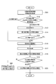
- FIG. 2 is a flowchart showing the operation of the estimation system of the present embodiment.
- the photographing unit 2 photographs the concrete surface of the target reinforced concrete by using the continuous photographing function, and transmits the photographed image to the estimation device 1.
- the photographing unit 2 of the present embodiment transmits a plurality of images taken at intervals (for example, 1 second interval to 1 hour interval) to the estimation device 1.
- the photographing unit 2 may take an image (moving image) of the concrete surface with a webcam or the like and distribute it to the estimation device 1.
- the estimation device 1 may take out a still image from the delivered video at a predetermined shooting interval, store it in the image storage unit 15, and analyze the image.
- the estimation device 1 receives the initial image of the initial state (first) transmitted from the photographing unit 2, analyzes the initial image, and extracts the characteristic color of the concrete in the dry state (S11).
- the estimation device 1 converts the feature color into digital information such as RGB and CMYK and stores it in the information storage unit 16.
- the estimation device 1 stores the image transmitted from the photographing unit 2 in the image storage unit 15.
- the estimation device 1 proceeds to S16 and proceeds to the neutralization estimation by water impregnation. In this case, the operator inputs the confirmed crack position and crack width into the estimation device 1 and stores them in the information storage unit 16.
- the estimation device 1 proceeds to S13 and visualizes the cracks by spraying water. This is because it is difficult to visually confirm the presence of minute cracks (0.1 mm width or less).
- the estimation device 1 transmits a control signal to the water supply unit 3.
- the water supply unit 3 sprays water on the target concrete surface according to the control of the estimation device 1 (S13). Moisture trapped in the crack openings enhances the absorption of light at the trapped location.
- the estimation device 1 detects a portion darker than the characteristic color of the dried concrete as a crack portion by analyzing an image obtained by photographing the concrete surface, and estimates the width of this dark portion as the crack width. can do.
- the water spraying by the water supply unit 3 it is sufficient to spray water as much as a mist, and it is sufficient to sufficiently wet the concrete surface of the target area, that is, to form a water film having a thickness of about 0.1 mm on the surface area of the target area. All you have to do is spray a lot of water.
- a drying device (not shown) may be used to promote drying by blowing warm air or the like.
- the estimation device 1 analyzes each image transmitted from the photographing unit 2 at a predetermined imaging interval, and an image when the concrete surface dries and approaches the initial image (first image). Is used to determine the presence or absence of cracks (S14).
- the image when approaching the initial image is an image in which the feature color of the initial image exceeds a predetermined ratio (for example, 90%) in the image.
- the estimation device 1 determines that there is a crack in the image when approaching the initial image if there is a portion having a predetermined color difference from the feature color, and if there is no portion having a predetermined color difference from the feature color, Judge that there is no crack. That is, the estimation device 1 detects a portion having a color darker than the feature color as a crack portion as compared with the feature color of the dried concrete acquired in S11, and the width of this dark portion (thickness of the line of the dark portion). Is estimated to be the crack width. When it is determined that there is a crack, the estimation device 1 acquires the detected position of the crack and the width of the crack by analyzing the image, and stores the detected crack in the information storage unit 16.
- the estimation device 1 ends the process.
- the estimation device 1 calculates the amount of water required to sufficiently impregnate the inside of the crack with water in order to determine the neutralization inside the crack (S16).
- the estimation device 1 calculates the minimum required water content using the crack width acquired in S14 and the crack depth estimated from the structure of the reinforced concrete, and the water content moisture content is equal to or higher than the calculated minimum required water content. The amount. Since the water content may be equal to or greater than the minimum required water content, the crack depth may be the maximum expected crack depth, such as the total length of the concrete thickness of the structure.
- the estimation device 1 calculates the area (107 cm 2 ) of the crack region from the following formula.
- the estimation device 1 calculates the total amount of impregnated water by multiplying the area of the concrete surface to be measured by the value converted per unit area (cm 2 ) (here, about 3 g / cm 2 ).
- the above 1 g may be calculated as the amount of water.
- the estimation device 1 transmits a control signal including the calculated impregnated water amount to the water supply unit 3.
- the water supply unit 3 impregnates the target concrete surface with the amount of water impregnated according to the control of the estimation device 1 (S17). For reinforced concrete installed outdoors, moisture impregnation due to rainfall may be utilized. Further, when the estimation device 1 impregnates only the cracked region with water, the estimation device 1 may include the cracked position in the control signal.
- the process proceeds to the second drying process (S18).
- the drying may be promoted by blowing warm air or the like using a drying device (not shown).
- the concrete component dissolves from the inside of the crack in the water inside the crack. At this time, if the inside of the crack is in a neutralized state, calcium hydroxide dissolves in water. The water in which calcium hydroxide is dissolved leaks to the concrete surface outside the crack, and then the water evaporates. As a result, the concrete surface in the vicinity of the cracked portion is in a state where white precipitates called efflorescence are formed.
- the cracked part when the cracked part is neutralized, it is in a state after the alkaline component contained in the concrete has leaked, so that it is in a rough state as compared with the concrete in the unneutralized area, and the moisture content. Holds strongly. Therefore, even on the concrete surface, moisture is strongly retained in the neutralized region near the crack and the concrete surface is observed to be discolored black, so that the discolored black portion can be estimated as the neutralized region.
- the estimation device 1 analyzes the image (third image) of the concrete surface, compares the color near the crack with the characteristic color of the concrete, and changes to blacker than the characteristic color.
- the region is estimated to be the neutralized region (S18).
- the estimation device 1 analyzes each image (continuously photographed image) transmitted from the photographing unit 2 at a predetermined photographing interval in the same manner as in the first drying process of S14, and the concrete surface is dried.
- the neutralized region is estimated using the image (third image) when approaching the initial image.
- the image when approaching the initial image is an image in which the feature color of the initial image exceeds a predetermined ratio (for example, 90%) in the image.
- the estimation device 1 analyzes this image and tentatively estimates a portion having a predetermined color difference from the feature color (that is, a portion blacker than the feature color) as a neutralized region. Then, it is stored in the information storage unit 16 (S18).
- the estimation device 1 analyzes an image (second image) of the concrete surface after the impregnated water is dried, and uses the color near the crack to determine whether the inside of the crack is neutralized. Estimate. That is, the estimation device 1 estimates the neutralization of the inside of the crack by using an image in which the impregnated water evaporates even inside the crack and the inside of the crack is dry.
- the image after drying (second image) is an image in which the color near the cracks is the same as the characteristic color of the concrete surface or white in the continuously photographed image.
- the estimation device 1 compares the color in the vicinity of the crack in the image (second image) with the characteristic color of the concrete surface (S19).
- the estimation device 1 when the estimation device 1 expresses a value of 0-255 in a grayscale display against a dark color, it determines that it is white when it is 50 or more larger than the characteristic color of concrete, and black when it is 30 or more smaller. judge.
- the estimation device estimates that the inside of the crack is not neutralized when the color near the crack is changed to whiter than the characteristic color (S19: white) (S21). In this case, the estimation device 1 discards the neutralized region estimated in S18. On the other hand, when the color in the vicinity of the crack is other than white (S19: other than white), the estimation device estimates that the inside of the crack is neutralized, and the neutralized region is the region estimated in S18 (S20). The estimation device 1 stores the estimation result in the information storage unit 16.
- FIG. 4 is a schematic view of an image in which white flowers indicating deneutralization occur in cracks on the concrete surface and an image showing an estimated neutralization region.
- FIG. 4A shows the positions of cracks on the concrete surface.
- FIG. 4B is an image example in which white flowers occur due to the precipitation of calcium carbonate indicating deneutralization in the vicinity of the crack position.
- FIG. 4C is an image example in which neutral water stays in the vicinity of the crack position and becomes black. The estimation device 1 estimates this blackened portion as a neutralized region.
- the estimation device 1 of the present embodiment described above acquires the characteristic color of the concrete from an initial image of the concrete surface of the reinforced concrete in a dry state, sprays moisture on the reinforced concrete, and then photographs the concrete surface.
- a determination unit 12 that analyzes the first image and determines that a portion having a predetermined color difference from the characteristic color is a crack, and a second image obtained by impregnating the crack with water and drying the concrete surface. It has an estimation unit 13 for estimating whether or not the inside of the crack is neutralized by analyzing the above and using the color in the vicinity of the crack.
- the cracked part of the reinforced concrete strongly traps water, and a remarkable color change occurs as compared with the non-cracked part.
- the water trapped in the cracks evaporates on the surface of the concrete, and the neutralization state inside can be estimated from the presence or absence of white deposits. From this, in the present embodiment, non-destructive and simple neutralization determination can be realized by discriminating the color of the cracked portion in the drying process after water impregnation.
- the estimation device 1 analyzes a third image of the concrete surface in the initial drying state after impregnation, compares the color in the vicinity of the crack with the feature color, and changes the color to blacker than the feature color.
- the region is estimated to be the neutralized region.
- the size of the neutralized area on the concrete surface is the maximum neutralized area in the depth direction of the crack, it can be regarded as the maximum corroded area of the metal buried in the concrete.
- the corrosion area In the case of electrochemically investigating metal corrosion in concrete, it is necessary to clarify the corrosion area, especially for evaluation of the corrosion rate. Therefore, in this embodiment, information that can be used for estimating the corrosion rate is obtained. Can be done.
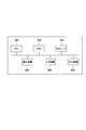
- a general-purpose computer system as shown in FIG. 5 can be used.
- the computer system shown is a CPU (Central Processing Unit, processor) 901, memory 902, storage 903 (HDD: Hard Disk Drive, SSD: Solid State Drive), communication device 904, input device 905, and output device. 906 and.
- the memory 902 and the storage 903 are storage devices.
- each function of the estimation device 1 is realized by executing a predetermined program loaded on the memory 902 by the CPU 901.
- the estimation device 1 may be mounted on one computer, or may be mounted on a plurality of computers. Further, the estimation device 1 may be a virtual machine mounted on a computer.
- the program of the estimation device 1 can be stored in a computer-readable recording medium such as an HDD, SSD, USB (Universal Serial Bus) memory, CD (Compact Disc), DVD (Digital Versatile Disc), or distributed via a network. You can also do it.
- a computer-readable recording medium such as an HDD, SSD, USB (Universal Serial Bus) memory, CD (Compact Disc), DVD (Digital Versatile Disc), or distributed via a network. You can also do it.
- Estimator 11 Image acquisition unit 12: Judgment unit 13: Estimate unit 14: Output unit 15: Image storage unit 16: Information storage unit 2: Imaging unit 3: Moisture supply unit
Landscapes
- Engineering & Computer Science (AREA)
- Physics & Mathematics (AREA)
- General Physics & Mathematics (AREA)
- Health & Medical Sciences (AREA)
- Life Sciences & Earth Sciences (AREA)
- Chemical & Material Sciences (AREA)
- Computer Vision & Pattern Recognition (AREA)
- Analytical Chemistry (AREA)
- General Health & Medical Sciences (AREA)
- Immunology (AREA)
- Pathology (AREA)
- Biochemistry (AREA)
- Theoretical Computer Science (AREA)
- Medicinal Chemistry (AREA)
- Food Science & Technology (AREA)
- Ceramic Engineering (AREA)
- Spectroscopy & Molecular Physics (AREA)
- Signal Processing (AREA)
- Quality & Reliability (AREA)
- Mathematical Physics (AREA)
- Investigating Materials By The Use Of Optical Means Adapted For Particular Applications (AREA)
- Investigating Or Analysing Materials By Optical Means (AREA)
Abstract
乾燥した状態の鉄筋コンクリートのコンクリート表面を撮影した初期画像から、前記コンクリートの特徴色を取得し、前記鉄筋コンクリートに水分を吹き付けた後に前記コンクリート表面を撮影した第1の画像を解析し、前記特徴色と所定の色差を有する部分をひび割れと判定する判定部12と、前記ひび割れに水分を含浸させ、乾燥させた後に前記コンクリート表面を撮影した第2の画像を解析し、前記ひび割れ近傍の色を用いて、前記ひび割れ内部が中性化しているか否かを推定する推定部13とを有する。
Description
本発明は、鉄筋コンクリートの中性化推定装置および中性化推定方法に関する。
鉄筋コンクリートは、鉄筋をコンクリートが防食する複合構造物である。コンクリートはアルカリ性であるため、健全な鉄筋コンクリートの中の鉄筋は腐食しない。しかし、コンクリートにひび割れが生じた際には、ひび割れ部からコンクリートの中性化が進行し、鉄筋の腐食が進行する。そのため、コンクリートにひび割れが生じたかどうか、および、ひび割れ内部の中性化が進行しているどうかは、鉄筋コンクリートの健全性を判定するための重要な基準である。
ひび割れの有無は、主に目視による点検項目である。また、画像解析よりひび割れを判定する技術も開発されている(非特許文献1、2参照)。
金子, 「デジタルカメラ画像を用いたコンクリート構造物のひび割れ検査技術」, NTT技術ジャーナル,(2011)
「AIを駆使して社会課題の解決目指す インフラ劣化度検査を省力化する「THE JUDGE!」開発チームの挑戦」、[online]、[2019年3月20日検索]、インターネット<URL:https://blogos.com/article/356591/>
鉄筋の腐食に関し、鉄筋コンクリートのひび割れ内部が中性化したかどうかは、鉄筋コンクリートの健全性を判断するうえで重要な基準となる。しかし、ひび割れ内部の中性化状況を測定するには、一部のコンクリートを斫るなどの破壊を伴う施工が必要となる。
本発明は、上記課題に鑑みてなされたものであり、本発明の目的は、鉄筋コンクリートを破壊する施工を行うことなく、簡便に鉄筋コンクリートの中性化を推定する技術を提供することにある。
上記目的を達成するため、本発明の一態様の中性化推定装置は、乾燥した状態の鉄筋コンクリートのコンクリート表面を撮影した初期画像から、前記コンクリートの特徴色を取得し、前記鉄筋コンクリートに水分を吹き付けた後に前記コンクリート表面を撮影した第1の画像を解析し、前記特徴色と所定の色差を有する部分をひび割れと判定する判定部と、前記ひび割れに水分を含浸させ、乾燥させた後に前記コンクリート表面を撮影した第2の画像を解析し、前記ひび割れ近傍の色を用いて、前記ひび割れ内部が中性化しているか否かを推定する推定部とを有する。
本発明の一態様は、中性化推定システムが行う中性化推定方法であって、乾燥した状態の鉄筋コンクリートのコンクリート表面を撮影した初期画像から、前記コンクリートの特徴色を取得する取得ステップと、前記鉄筋コンクリートに水分を吹き付ける水分吹付ステップと、水分を吹き付けた後に前記コンクリート表面を撮影した第1の画像を解析し、前記特徴色と所定の色差を有する部分をひび割れと判定する判定ステップと、前記ひび割れに水分を含浸する含浸ステップと、前記含浸ステップの水分を乾燥させた後に前記コンクリート表面を撮影した第2の画像を解析し、前記ひび割れ近傍の色を用いて、前記ひび割れ内部が中性化しているか否かを推定する推定ステップとを有する。
本発明によれば、鉄筋コンクリートを破壊する施工を行うことなく、簡便に鉄筋コンクリートの中性化を推定する技術を提供することができる。
以下、本発明の実施の形態について、図面を参照して説明する。図面の記載において、同一部分には同一符号を付して説明を省略する。
(中性化推定システムの全体構成)
図1は、本実施形態の中性化推定システムの全体構成図である。中性化推定システムは、鉄筋コンクリート(鉄筋コンクリート構造物)の中性化を推定する。鉄筋コンクリートには、コンクリートの内部に複数の鉄筋が配置されている。本実施形態の中性化推定システムは、推定装置1と、撮影部2と、水分供給部3とを備える。
図1は、本実施形態の中性化推定システムの全体構成図である。中性化推定システムは、鉄筋コンクリート(鉄筋コンクリート構造物)の中性化を推定する。鉄筋コンクリートには、コンクリートの内部に複数の鉄筋が配置されている。本実施形態の中性化推定システムは、推定装置1と、撮影部2と、水分供給部3とを備える。
撮影部2(撮影装置)は、鉄筋コンクリートのコンクリート表面の画像(静止画または動画)を撮影するカメラである。撮影部2は、コンクリート表面に生じた微細な(例えば、0.1mm幅程度の)ひび割れを捕捉可能な画像が取得できる位置に、固定して設置される。撮影部2は、撮影した画像を推定装置1に送信する。
撮影部2は、少なくとも連続撮影機能を有し、例えば、インターバル撮影機能、動画から所定のタイミングで画像を取り出す機能等を有してもよい。インターバル撮影の撮影間隔は、1秒間隔から1時間間隔の任意の時間を設定可能である。
本実施形態では、撮影部2は、最初に、乾燥した状態のコンクリート表面を撮影した初期画像を推定装置1に送信する。その後、撮影部2は、所定の間隔でインターバル撮影した静止画の複数の画像、または、動画を、連続撮影画像として推定装置1に送信する。
水分供給部3(水分供給装置)は、推定装置1の制御に従って、鉄筋コンクリートのコンクリート表面に水分を供給する。なお、本実施形態では、水分の供給は、推定装置1および水分供給部3により行うが、降雨を活用してもよい。また、人がひび割れに水分を供給してもよい。
推定装置1は、撮影部2が鉄筋コンクリートのコンクリート表面を撮影した画像を、画像解析し、ひび割れ内部が中性化しているか否かを推定する。図示する推定装置は、処理装置と、記憶装置とを有する。処理装置は、画像取得部11と、判定部12と、推定部13と、出力部14とを有し、記憶装置は、画像記憶部15と、情報記憶部16とを有する。
画像取得部11は、撮影部2から送信または配信される画像を画像記憶部15に記憶する。撮影部2は、初期画像と、その後の連続撮影機能を用いて撮影した複数の画像(連続撮影画像)とを送信する。画像取得部11は、初期画像および連続撮影画像を受信し、画像記憶部15に記憶する。
判定部12は、乾燥した状態の鉄筋コンクリートのコンクリート表面を撮影した初期画像から、コンクリートの特徴色を取得し、情報記憶部16に記憶する。判定部12は、鉄筋コンクリートに水分を吹き付けた後の乾燥過程においてコンクリート表面を撮影した画像(第1の画像)を解析し、特徴色と所定の色差を有する部分をひび割れと判定する。なお、判定部12は、連続撮影画像の中で、特徴色の部分が所定の割合を超えた画像(第1の画像)を用いて、ひび割れを判定する。
推定部13は、水分供給部3を制御して、ひび割れに水分を含浸させ、乾燥させた後に前記コンクリート表面を撮影した画像(第2の画像)を解析し、ひび割れ近傍の色を用いて、ひび割れ内部が中性化しているか否かを推定する。具体的には、推定部13は、ひび割れ内部の中性化を判定するために、ひび割れ内部に十分に水分を含浸させるのに必要な水分量を算出する。推定部13は、乾燥させた後の画像(第2の画像)のひび割れ近傍の色を特徴色と比較し、ひび割れ近傍の色が特徴色より白く変化している場合、ひび割れ内部は中性化していないと推定する。
推定部13は、含浸後の乾燥初期状態の前記コンクリート表面を撮影した画像(第3の画像)を解析し、ひび割れ近傍の色を特徴色と比較し、特徴色より黒く変化している領域を中性化領域と推定する。
出力部14は、判定結果および推定結果を、ディスプレイ、プリンタなどの出力装置に出力する。また、出力部14は、ネットワークを介して他の装置に判定結果および推定結果を送信してもよい。
画像記憶部15には、初期画像と、連続撮影機能により撮影された複数の画像(連続撮影画像)が記憶される。情報記憶部16には、コンクリートの特徴色、ひび割れ位置、ひび割れ幅、含浸水分量、中性化推定結果、中性化領域などの各種情報が記憶される。
(中性化推定システムの動作)
本実施形態では、鉄筋コンクリートへpH7-8の中性水を含浸させ、その後の乾燥過程の色変化を観測することでひび割れ内部が中性化しているか否かを推定し、中性化領域を推定する。ひび割れのないコンクリート表面は水にぬれることでやや濃いグレーに変色するが、ひび割れが発生している部分(ひび割れ部)のコンクリート表面と比較して水分含浸が進みにくい。そのため、ひび割れのないコンクリート表面は、乾燥も短い時間で終了し、もとのコンクリートの色(グレー)に戻る。一方、ひび割れ部のコンクリート表面には、水分が多く滞留しており、乾燥も長時間を要する。
本実施形態では、鉄筋コンクリートへpH7-8の中性水を含浸させ、その後の乾燥過程の色変化を観測することでひび割れ内部が中性化しているか否かを推定し、中性化領域を推定する。ひび割れのないコンクリート表面は水にぬれることでやや濃いグレーに変色するが、ひび割れが発生している部分(ひび割れ部)のコンクリート表面と比較して水分含浸が進みにくい。そのため、ひび割れのないコンクリート表面は、乾燥も短い時間で終了し、もとのコンクリートの色(グレー)に戻る。一方、ひび割れ部のコンクリート表面には、水分が多く滞留しており、乾燥も長時間を要する。
そのため乾燥過程においては、コンクリート表面の大部分が乾燥しながら、ひび割れ部のコンクリート表面のみに水分が滞留する時間が存在し、この時間を用いてひび割れ部の検出および中性化を判定する。ひび割れのないコンクリート表面の乾燥状態の色は、水分含浸前のコンクリートの画像情報を事前に取得しておくことで判定すればよい。また乾燥は常温大気放置で乾燥しても、温風吹付等による乾燥促進を実施してもかまわない。
図2は、本実施形態の推定システムの動作を示すフローチャートである。
本実施形態では、撮影部2は、対象とする鉄筋コンクリートのコンクリート表面を、連続撮影機能を用いて撮影し、撮影した画像を推定装置1に送信する。本実施形態の撮影部2は、所定の撮影間隔(例えば1秒間隔~1時間間隔)でインターバル撮影した複数の画像を推定装置1に送信する。なお、撮影部2は、ウェブカメラなどであって、コンクリート表面の映像(動画)を撮影し、推定装置1に配信してもよい。この場合、推定装置1は、配信された映像の中から所定の撮影間隔で静止画を取り出し、画像記憶部15に記憶し、画像解析してもよい。
まず、推定装置1は、撮影部2から送信される初期状態(最初)の初期画像を受信し、当該初期画像を画像解析して、乾燥した状態のコンクリートの特徴色を抽出する(S11)。なお、推定装置1は、特徴色を、RGB、CMYKなどのデジタル情報とし、情報記憶部16に記憶する。なお、推定装置1は、撮影部2から送信される画像を、画像記憶部15に記憶する。
コンクリート表面のひび割れ(ひび割れ位置、ひび割れ幅)を、事前に目視で確認できる場合は(S12:ひび割れあり)、推定装置1はS16に進み、水分含浸による中性化推定に移行する。この場合、作業者は、確認したひび割れの位置およびひび割れ幅を推定装置1に入力し、情報記憶部16に記憶する。
コンクリート表面のひび割れを事前に確認できない場合は(S12:ひび割れ不明)、推定装置1はS13に進み、水分吹付けによりひび割れを可視化する。微小なひび割れ(0.1mm幅以下の)が存在する場合は、目視での確認が困難であるためである。
ひび割れの可視化では、推定装置1は、水分供給部3に制御信号を送信する。水分供給部3は、推定装置1の制御に従って、対象のコンクリート表面に水分を吹き付ける(S13)。ひび割れの開口部に捕捉された水分は、捕捉された位置での光の吸収を強める。これにより、推定装置1は、コンクリート表面を撮影した画像を解析することで、乾燥したコンクリートの特徴色よりも暗い色の部分を、ひび割れ部として検出し、この暗い部分の幅をひび割れ幅と推定することができる。
水分供給部3による水分吹付は、霧吹き程度の水の吹きかけで十分であり、対象範囲のコンクリート表面を十分に濡らす程度、すなわち、対象範囲の表面積に約0.1mm厚の水膜が生じるのに十分な水分を吹きかければよい。
その後、第1の乾燥過程に移行する(S14)。乾燥は、常温大気中に放置して乾燥しても、乾燥装置(不図示)により温風吹付等による乾燥を促進してよい。
第1乾燥過程において、推定装置1は、撮影部2から所定の撮影間隔で送信される各画像を画像解析し、コンクリート表面が乾燥して初期画像に近づいたときの画像(第1の画像)を用いて、ひび割れの有無を判定する(S14)。初期画像に近づいたときの画像は、画像の中で初期画像の特徴色が所定の割合(例えば、90%)を超えた画像である。
推定装置1は、初期画像に近づいたときの画像において、特徴色と所定の色差が生じた部分がある場合はひび割れがあると判定し、特徴色と所定の色差が生じた部分がない場合、ひび割れがないと判定する。すなわち、推定装置1は、S11で取得した乾燥したコンクリートの特徴色と比較して、特徴色よりも暗い色の部分を、ひび割れ部として検出し、この暗い部分の幅(暗い部分の線の太さ)を、ひび割れ幅と推定する。ひび割れがあると判定した場合、推定装置1は、検出したひび割れの位置およびひび割れの幅を、前記画像を解析することで取得し、情報記憶部16に記憶する。
ひび割れがない場合(S15:なし)、推定装置1は処理終了する。ひび割れがある場合(S15:あり)、推定装置1は、ひび割れ内部の中性化を判定するために、ひび割れ内部に十分に水分を含浸させるのに必要な水分量を算出する(S16)。推定装置1は、必要最低限の水分量を、S14で取得したひび割れ幅と、鉄筋コンクリートの構造から推定されるひび割れ深さとを用いて算出し、算出した必要最低限の水分量以上を、含水水分量とする。必要最低限の水分量以上を含水水分量とすればよいことから、ひび割れ深さは構造物のコンクリート厚さ全長とするなど、想定されるひび割れの最大深さとすればよい。
例えば、図3に示す中空のコンクリートの半周分に幅0.1 mmのひび割れが生じた場合、推定装置1は、そのひび割れ領域の面積(107cm2)を、以下の式より算出する。
{(23/2)2×π-(16/2)2×π}/2 = 107cm2
そして、推定装置1は、ひび割れ領域の面積(107cm2)に、ひび割れ幅(0.01cm)を乗算し、ひび割れの空間(107cm2×0.01cm=1.07 cm3)を算出する。推定装置1は、約1.07 cm3の空間が生じているため、これを満たすのに十分な水分量として、1.07gを算出する。
本実施形態では、S13の水分吹付と同様に、対象のコンクリート表面全体に水分を含浸させる。そのため、推定装置1は、単位面積(cm2)当たりに換算した値(ここでは約3g/cm2)を、測定対象のコンクリート表面の面積に乗算することで含浸水分量の総量を算出する。単位面積当たりに換算した値(約3g/cm2)は、コンクリートの半周分の長さ(23×π/2=36.13cm)に、幅0.1 mmのひび割れを乗算し(36.13×0.01=0.36cm2)、ひび割れの空間を満たす水分量を前記乗算した値で除算した値(1.07g/0.36cm2=2.96g/cm2)である。
なお、水分供給部3が、ひび割れ領域にのみ水分を含浸させる機構を有する場合は、上記1gを水分量として算出してもよい。
推定装置1は、算出した含浸水分量を含む制御信号を、水分供給部3に送信する。水分供給部3は、推定装置1の制御に従って、対象のコンクリート表面に、含浸水分量の水分を含浸する(S17)。なお、屋外に設置された鉄筋コンクリートに関しては、降雨による水分含浸等を活用してもよい。また、推定装置1は、ひび割れ領域にのみ水分を含浸させる場合、制御信号にひび割れ位置を含めてもよい。
ひび割れ領域を含むコンクリート表面全体への十分な水分の含浸後、第2の乾燥過程に移行する(S18)。乾燥は、常温大気中に放置して乾燥しても、乾燥装置(不図示)により温風吹付等による乾燥促進を実施してよい。
ひび割れ内部の水分には、ひび割れ内部からコンクリート成分が溶解する。このとき、ひび割れ内部が未中性化状態の場合、水酸化カルシウムが水分に溶解する。水酸化カルシウムが溶解した水分は、ひび割れ外部のコンクリート表面へと漏洩し、その後、水分が蒸発する。これにより、ひび割れ部近傍のコンクリート表面は、白華(エフロレッセンス)と呼ばれる白い析出物が生じる状態となる。
一方、ひび割れ内部が中性化していた場合には、ひび割れ内部で水酸化カルシウムが炭酸カルシウムに変化し、水分への溶解度が小さくなる。このため、水分には白華する成分は溶解せず、中性の水分がひび割れ外部のコンクリート表面に漏洩し、蒸発する。ひび割れ部に中性の水分が保持された状態の領域は、光の反射量が減少するため、他の領域に比べ黒く見える。
また、ひび割れ部が中性化している場合、コンクリートに含まれていたアルカリ成分が漏出した後の状態であるため、未中性化領域のコンクリートと比較して粗な状態となっており、水分を強く保持する。そのため、コンクリート表面においてもひび割れ近傍で中性化した領域で水分を強く保持され黒く変色して観測されるため、黒く変色した部分を中性化領域と推定できる。
このように、第2の乾燥過程において、ひび割れ部からコンクリート表面に水分が浸みだし、蒸発する際にアルカリ成分を含むか否かが、白い析出物により判別可能である。したがって、白い析出物の有無により、ひび割れ内部の中性化の判別が可能となる。
含浸後の第2乾燥過程において、推定装置1は、コンクリート表面を撮影した画像(第3の画像)を解析し、ひび割れ近傍の色をコンクリートの特徴色と比較し、特徴色より黒く変化している領域を中性化領域と推定する(S18)。
具体的には、推定装置1は、S14の第1乾燥過程と同様に、撮影部2から所定の撮影間隔で送信される各画像(連続撮影画像)を画像解析し、コンクリート表面が乾燥して初期画像に近づいたときの画像(第3の画像)を用いて、中性化領域を推定する。初期画像に近づいたときの画像は、画像の中で初期画像の特徴色が所定の割合(例えば、90%)を超えた画像である。
水分を含浸し、乾燥が開始されたコンクリート表面では水分の蒸発が進み、S14と同様に、ひび割れに捕捉された水分が残った状態となる。白華は、ひび割れ内部の水分の蒸発が進んだ段階で生じるため、第2の乾燥過程の初期画像に近づいたときの画像(第3の画像)にはひび割れが黒く検出される。S17で十分な水分を含浸させていることから、推定装置1は、この画像を解析し、特徴色と所定の色差を有する部分(すなわち、特徴色より黒い部分)を中性化領域と仮に推定し、情報記憶部16に記憶する(S18)。
その後、乾燥が十分に進んだ際には白華の判別が可能となる。このとき、推定装置1は、含浸させた水分を乾燥させた後にコンクリート表面を撮影した画像(第2の画像)を解析し、ひび割れ近傍の色を用いて、ひび割れ内部が中性化しているか否かを推定する。すなわち、推定装置1は、含浸した水分がひび割れ内部においても蒸発し、ひび割れ内部が乾燥した状態の画像を用いて、ひび割れ内部の中性化を推定する。乾燥後の画像(第2の画像)は、連続撮影画像の中でひび割れ近傍の色が、コンクリート表面の特徴色と同じ、または、白色となった画像である。
色を用いた画像解析については、例えば、非特許文献1などに記載されている。本実施形態では、推定装置1は、前記画像(第2の画像)のひび割れ近傍の色を、コンクリート表面の特徴色と比較する(S19)。
例えば、推定装置1は、暗色を背景としたグレースケール表示にて0-255の値で表現する場合、コンクリートの特徴色よりも50以上大きい場合に白色と判定し、30以上小さい場合に黒色と判定する。
推定装置は、ひび割れ近傍の色が特徴色より白く変化している場合(S19:白)、ひび割れ内部は中性化していないと推定する(S21)。この場合、推定装置1は、S18で推定した中性化領域を破棄する。一方、推定装置は、ひび割れ近傍の色が白以外の場合(S19:白以外)、ひび割れ内部は中性化していると推定し、中性化領域をS18で推定した領域とする(S20)。推定装置1は、推定結果を情報記憶部16に記憶する。
図4は、コンクリート表面のひび割れにおいて、未中性化を示す白華が生じた画像と、中性化推定領域を示す画像の模式図である。図4(a)は、コンクリート表面のひび割れの位置を示す。図4(b)は、ひび割れの位置の近傍に、未中性化を示す炭酸カルシウムの析出による白華が生じた場合の画像例である。図4(c)は、ひび割れの位置の近傍に中性水が滞留し、黒くなっている場合の画像例である。推定装置1は、この黒くなっている部分を中性化領域と推定する。
なお、過去の白華がすでにコンクリート表面に現れている場合には、本実施形態による白華との判別が困難となることから、過去の白華を除去しておくことが望ましい。
以上説明した本実施形態の推定装置1は、乾燥した状態の鉄筋コンクリートのコンクリート表面を撮影した初期画像から、前記コンクリートの特徴色を取得し、前記鉄筋コンクリートに水分を吹き付けた後に前記コンクリート表面を撮影した第1の画像を解析し、前記特徴色と所定の色差を有する部分をひび割れと判定する判定部12と、前記ひび割れに水分を含浸させ、乾燥させた後に前記コンクリート表面を撮影した第2の画像を解析し、前記ひび割れ近傍の色を用いて、前記ひび割れ内部が中性化しているか否かを推定する推定部13とを有する。
すなわち、鉄筋コンクリートのひび割れ部分では、水分を強く捕捉し、ひび割れのない部分と比較し、顕著な色の変化が生じる。また、ひび割れに捕捉された水分は、コンクリートの表面で蒸発し、白い析出物の有無で内部の中性化状態を推定できる。このことから、本実施形態では、水分含浸後の乾燥過程において、ひび割れ部の色を判別することで、非破壊で簡便な中性化判定を実現することができる。
本実施形態では、ひび割れの中性化または未中性化を判定できるため、ひび割れ後の鉄筋コンクリート構造物の健全性が判定可能となり、適切な設備保全を実現することができる。
本実施形態では、推定装置1は、含浸後の乾燥初期状態の前記コンクリート表面を撮影した第3の画像を解析し、前記ひび割れ近傍の色を前記特徴色と比較し、前記特徴色より黒く変化している領域を中性化領域と推定する。
コンクリート表面の中性化領域の大きさは、ひび割れの奥行き方向にかけて最大の中性化領域であるため、コンクリート中に埋設された金属の最大腐食面積とみなすことができる。コンクリート中の金属腐食を電気化学的に調査する場合、特に腐食速度の評価には腐食面積を明らかにする必要があることから、本実施形態では、腐食速度の推定に活用可能な情報を得ることが出来る。
なお、上記説明した推定装置1には、例えば、図5に示すような汎用的なコンピュータシステムを用いることができる。図示するコンピュータシステムは、CPU(Central Processing Unit、プロセッサ)901と、メモリ902と、ストレージ903(HDD:Hard Disk Drive、SSD:Solid State Drive)と、通信装置904と、入力装置905と、出力装置906とを備える。メモリ902およびストレージ903は、記憶装置である。このコンピュータシステムにおいて、CPU901がメモリ902上にロードされた所定のプログラムを実行することにより、推定装置1の各機能が実現される。また、推定装置1は、1つのコンピュータで実装されてもよく、あるいは複数のコンピュータで実装されても良い。また、推定装置1は、コンピュータに実装される仮想マシンであっても良い。
推定装置1のプログラムは、HDD、SSD、USB(Universal Serial Bus)メモリ、CD (Compact Disc)、DVD (Digital Versatile Disc)などのコンピュータ読取り可能な記録媒体に記憶することも、ネットワークを介して配信することもできる。
また、本発明は上記実施形態に限定されるものではなく、その要旨の範囲内で数々の変形が可能である。
1 :推定装置
11:画像取得部
12:判定部
13:推定部
14:出力部
15:画像記憶部
16:情報記憶部
2 :撮影部
3 :水分供給部
11:画像取得部
12:判定部
13:推定部
14:出力部
15:画像記憶部
16:情報記憶部
2 :撮影部
3 :水分供給部
Claims (6)
- 乾燥した状態の鉄筋コンクリートのコンクリート表面を撮影した初期画像から、前記コンクリートの特徴色を取得し、前記鉄筋コンクリートに水分を吹き付けた後に前記コンクリート表面を撮影した第1の画像を解析し、前記特徴色と所定の色差を有する部分をひび割れと判定する判定部と、
前記ひび割れに水分を含浸させ、乾燥させた後に前記コンクリート表面を撮影した第2の画像を解析し、前記ひび割れ近傍の色を用いて、前記ひび割れ内部が中性化しているか否かを推定する推定部と
を有する中性化推定装置。 - 前記推定部は、第2の画像の前記ひび割れ近傍の色を前記特徴色と比較し、前記ひび割れ近傍の色が前記特徴色より白く変化している場合、前記ひび割れ内部は中性化していないと推定する
請求項1記載の中性化推定装置。 - 第1の画像は、前記特徴色の部分が所定の割合を超えた画像である
請求項1または2記載の中性化推定装置。 - 前記推定部は、含浸後の乾燥過程で前記コンクリート表面を撮影した第3の画像を解析し、前記ひび割れ近傍の色を前記特徴色と比較し、前記特徴色より黒く変化している領域を中性化領域と推定する
請求項1から3のいずれか1項に記載の中性化推定装置。 - 中性化推定システムが行う中性化推定方法であって、
乾燥した状態の鉄筋コンクリートのコンクリート表面を撮影した初期画像から、前記コンクリートの特徴色を取得する取得ステップと、
前記鉄筋コンクリートに水分を吹き付ける水分吹付ステップと、
水分を吹き付けた後に前記コンクリート表面を撮影した第1の画像を解析し、前記特徴色と所定の色差を有する部分をひび割れと判定する判定ステップと、
前記ひび割れに水分を含浸する含浸ステップと、
前記含浸ステップの水分を乾燥させた後に前記コンクリート表面を撮影した第2の画像を解析し、前記ひび割れ近傍の色を用いて、前記ひび割れ内部が中性化しているか否かを推定する推定ステップと
を有する中性化推定方法。 - 前記推定ステップは、第2の画像の前記ひび割れ近傍の色を前記特徴色と比較し、前記ひび割れ近傍の色が前記特徴色より白く変化している場合、前記ひび割れ内部は中性化していないと推定する
請求項5記載の中性化推定方法。
Priority Applications (3)
| Application Number | Priority Date | Filing Date | Title |
|---|---|---|---|
| JP2021530450A JP7236008B2 (ja) | 2019-07-11 | 2019-07-11 | 中性化推定装置および中性化推定方法 |
| PCT/JP2019/027493 WO2021005779A1 (ja) | 2019-07-11 | 2019-07-11 | 中性化推定装置および中性化推定方法 |
| US17/624,888 US20220301150A1 (en) | 2019-07-11 | 2019-07-11 | Neutralization Estimating Apparatus and Neutralization Estimating Method |
Applications Claiming Priority (1)
| Application Number | Priority Date | Filing Date | Title |
|---|---|---|---|
| PCT/JP2019/027493 WO2021005779A1 (ja) | 2019-07-11 | 2019-07-11 | 中性化推定装置および中性化推定方法 |
Publications (1)
| Publication Number | Publication Date |
|---|---|
| WO2021005779A1 true WO2021005779A1 (ja) | 2021-01-14 |
Family
ID=74114489
Family Applications (1)
| Application Number | Title | Priority Date | Filing Date |
|---|---|---|---|
| PCT/JP2019/027493 Ceased WO2021005779A1 (ja) | 2019-07-11 | 2019-07-11 | 中性化推定装置および中性化推定方法 |
Country Status (3)
| Country | Link |
|---|---|
| US (1) | US20220301150A1 (ja) |
| JP (1) | JP7236008B2 (ja) |
| WO (1) | WO2021005779A1 (ja) |
Families Citing this family (1)
| Publication number | Priority date | Publication date | Assignee | Title |
|---|---|---|---|---|
| EP3889588A4 (en) * | 2018-11-29 | 2022-01-26 | FUJIFILM Corporation | INSPECTION ASSIST DEVICE, INSPECTION ASSIST METHOD AND INSPECTION ASSIST PROGRAM FOR CONCRETE STRUCTURE |
Citations (7)
| Publication number | Priority date | Publication date | Assignee | Title |
|---|---|---|---|---|
| JPH07280743A (ja) * | 1994-04-11 | 1995-10-27 | Kubota Corp | コンクリートの亀裂監視方法 |
| JP2000028542A (ja) * | 1998-07-10 | 2000-01-28 | Ishikawajima Harima Heavy Ind Co Ltd | コンクリート劣化度数量化システム |
| JP2012202859A (ja) * | 2011-03-25 | 2012-10-22 | Railway Technical Research Institute | コンクリート表面の変状領域の検出方法 |
| JP2013238415A (ja) * | 2012-05-11 | 2013-11-28 | Kajima Corp | コンクリート構造物の品質評価方法 |
| JP2016095198A (ja) * | 2014-11-13 | 2016-05-26 | 株式会社Ihiインフラシステム | コンクリート劣化診断装置 |
| WO2017047315A1 (ja) * | 2015-09-16 | 2017-03-23 | 富士フイルム株式会社 | 健全度判定装置、健全度判定方法および健全度判定プログラム |
| KR101848067B1 (ko) * | 2016-11-07 | 2018-04-11 | 전남대학교산학협력단 | 디지털이미지프로세싱을 이용한 콘크리트중성화영역 검출방법 |
Family Cites Families (5)
| Publication number | Priority date | Publication date | Assignee | Title |
|---|---|---|---|---|
| US6959270B2 (en) * | 2001-05-24 | 2005-10-25 | UNIVERSITé LAVAL | Method for modeling the transport of ions in hydrated cement systems |
| US7551058B1 (en) * | 2003-12-10 | 2009-06-23 | Advanced Design Consulting Usa, Inc. | Sensor for monitoring environmental parameters in concrete |
| US9436783B2 (en) * | 2013-03-01 | 2016-09-06 | Simco Technologies Inc. | Method and system for estimating degradation and durability of concrete structures and asset management system making use of same |
| KR101323708B1 (ko) * | 2013-03-05 | 2013-10-30 | 한국건설기술연구원 | 콘크리트 탄산화의 반정량적 평가방법 및 이를 이용한 콘크리트 탄산화의 반정량적 평가장치 |
| NZ712434A (en) * | 2013-03-20 | 2020-06-26 | Halok Pty Ltd | Method of assessing the reactivity of a polymerizable material in forming a geopolymer |
-
2019
- 2019-07-11 JP JP2021530450A patent/JP7236008B2/ja active Active
- 2019-07-11 WO PCT/JP2019/027493 patent/WO2021005779A1/ja not_active Ceased
- 2019-07-11 US US17/624,888 patent/US20220301150A1/en not_active Abandoned
Patent Citations (7)
| Publication number | Priority date | Publication date | Assignee | Title |
|---|---|---|---|---|
| JPH07280743A (ja) * | 1994-04-11 | 1995-10-27 | Kubota Corp | コンクリートの亀裂監視方法 |
| JP2000028542A (ja) * | 1998-07-10 | 2000-01-28 | Ishikawajima Harima Heavy Ind Co Ltd | コンクリート劣化度数量化システム |
| JP2012202859A (ja) * | 2011-03-25 | 2012-10-22 | Railway Technical Research Institute | コンクリート表面の変状領域の検出方法 |
| JP2013238415A (ja) * | 2012-05-11 | 2013-11-28 | Kajima Corp | コンクリート構造物の品質評価方法 |
| JP2016095198A (ja) * | 2014-11-13 | 2016-05-26 | 株式会社Ihiインフラシステム | コンクリート劣化診断装置 |
| WO2017047315A1 (ja) * | 2015-09-16 | 2017-03-23 | 富士フイルム株式会社 | 健全度判定装置、健全度判定方法および健全度判定プログラム |
| KR101848067B1 (ko) * | 2016-11-07 | 2018-04-11 | 전남대학교산학협력단 | 디지털이미지프로세싱을 이용한 콘크리트중성화영역 검출방법 |
Also Published As
| Publication number | Publication date |
|---|---|
| US20220301150A1 (en) | 2022-09-22 |
| JPWO2021005779A1 (ja) | 2021-01-14 |
| JP7236008B2 (ja) | 2023-03-09 |
Similar Documents
| Publication | Publication Date | Title |
|---|---|---|
| JP4672680B2 (ja) | 画像処理方法、画像処理装置、画像処理プログラム及びそのプログラムを記録したコンピュータ読み取り可能な記録媒体 | |
| JP2025094214A (ja) | 学習用データ収集装置、学習用データ収集方法、及びプログラム | |
| RU2009107143A (ru) | Устройство обработки изображений и способ обработки изображений | |
| JP5706233B2 (ja) | 鋼材成分識別装置及びそのプログラム | |
| CN104777174B (zh) | 轴类零件截面突变部位表面疲劳裂纹检测系统及方法 | |
| CN107404628B (zh) | 图像处理装置及方法以及监视系统 | |
| CN106770325B (zh) | 一种混凝土构件裂缝自动检测方法 | |
| WO2021005779A1 (ja) | 中性化推定装置および中性化推定方法 | |
| WO2009044148A8 (en) | Apparatus and method of image analysis | |
| US9014426B2 (en) | Method and device for the detection of moving objects in a video image sequence | |
| CN107424373A (zh) | 外力入侵检测方法和装置及系统 | |
| JP2019074339A (ja) | コンクリートの劣化の早期検知方法 | |
| KR102712607B1 (ko) | 이미지 촬영 기반 건축물 관리 시스템 및 이의 실행 방법 | |
| JP2009217725A (ja) | 監視装置及び監視方法 | |
| CN110659590A (zh) | 刮板输送机的监控方法、装置、设备和存储介质 | |
| JP6597666B2 (ja) | 耐候性鋼の腐食環境判定システム、耐候性鋼の腐食劣化予測システムおよびそれを用いたビジネス商品 | |
| JP4604357B2 (ja) | 補修コスト計算システム、補修コスト計算システムをコンピュータにより実現するためのプログラム、およびこのプログラムを記録したコンピュータ読取可能な記録媒体 | |
| KR101148029B1 (ko) | 3d 카메라를 이용한 영상인식장치 및 방법 | |
| CN114187368A (zh) | 建筑板材的暗纹检测方法、装置、电子设备及存储介质 | |
| JP2003329594A (ja) | 建造物塗装面の劣化診断方法 | |
| Widiasri et al. | Computer vision system in measurement of the volume and mass of egg using the disc method | |
| JP2016090360A (ja) | 打継面処理の評価方法及び評価装置 | |
| JP4751871B2 (ja) | 撮像対象検出装置および方法 | |
| Bison et al. | Evaluation of frescoes detachments by partial least square thermography | |
| JP7187830B2 (ja) | 画像処理プログラム、画像処理装置、及び画像処理方法 |
Legal Events
| Date | Code | Title | Description |
|---|---|---|---|
| 121 | Ep: the epo has been informed by wipo that ep was designated in this application |
Ref document number: 19936995 Country of ref document: EP Kind code of ref document: A1 |
|
| ENP | Entry into the national phase |
Ref document number: 2021530450 Country of ref document: JP Kind code of ref document: A |
|
| NENP | Non-entry into the national phase |
Ref country code: DE |
|
| 122 | Ep: pct application non-entry in european phase |
Ref document number: 19936995 Country of ref document: EP Kind code of ref document: A1 |