WO2021005659A1 - 情報処理システム、センサシステム、情報処理方法及びプログラム - Google Patents
情報処理システム、センサシステム、情報処理方法及びプログラム Download PDFInfo
- Publication number
- WO2021005659A1 WO2021005659A1 PCT/JP2019/026866 JP2019026866W WO2021005659A1 WO 2021005659 A1 WO2021005659 A1 WO 2021005659A1 JP 2019026866 W JP2019026866 W JP 2019026866W WO 2021005659 A1 WO2021005659 A1 WO 2021005659A1
- Authority
- WO
- WIPO (PCT)
- Prior art keywords
- information
- unit
- pixel
- processing system
- information processing
- Prior art date
- Legal status (The legal status is an assumption and is not a legal conclusion. Google has not performed a legal analysis and makes no representation as to the accuracy of the status listed.)
- Ceased
Links
Images


Classifications
-
- G—PHYSICS
- G01—MEASURING; TESTING
- G01S—RADIO DIRECTION-FINDING; RADIO NAVIGATION; DETERMINING DISTANCE OR VELOCITY BY USE OF RADIO WAVES; LOCATING OR PRESENCE-DETECTING BY USE OF THE REFLECTION OR RERADIATION OF RADIO WAVES; ANALOGOUS ARRANGEMENTS USING OTHER WAVES
- G01S17/00—Systems using the reflection or reradiation of electromagnetic waves other than radio waves, e.g. lidar systems
- G01S17/88—Lidar systems specially adapted for specific applications
- G01S17/89—Lidar systems specially adapted for specific applications for mapping or imaging
- G01S17/894—Three-dimensional [3D] imaging with simultaneous measurement of time-of-flight at a two-dimensional [2D] array of receiver pixels, e.g. time-of-flight cameras or flash lidar
-
- G—PHYSICS
- G01—MEASURING; TESTING
- G01S—RADIO DIRECTION-FINDING; RADIO NAVIGATION; DETERMINING DISTANCE OR VELOCITY BY USE OF RADIO WAVES; LOCATING OR PRESENCE-DETECTING BY USE OF THE REFLECTION OR RERADIATION OF RADIO WAVES; ANALOGOUS ARRANGEMENTS USING OTHER WAVES
- G01S17/00—Systems using the reflection or reradiation of electromagnetic waves other than radio waves, e.g. lidar systems
- G01S17/02—Systems using the reflection of electromagnetic waves other than radio waves
- G01S17/06—Systems determining position data of a target
- G01S17/08—Systems determining position data of a target for measuring distance only
- G01S17/32—Systems determining position data of a target for measuring distance only using transmission of continuous waves, whether amplitude-, frequency-, or phase-modulated, or unmodulated
- G01S17/36—Systems determining position data of a target for measuring distance only using transmission of continuous waves, whether amplitude-, frequency-, or phase-modulated, or unmodulated with phase comparison between the received signal and the contemporaneously transmitted signal
-
- G—PHYSICS
- G01—MEASURING; TESTING
- G01S—RADIO DIRECTION-FINDING; RADIO NAVIGATION; DETERMINING DISTANCE OR VELOCITY BY USE OF RADIO WAVES; LOCATING OR PRESENCE-DETECTING BY USE OF THE REFLECTION OR RERADIATION OF RADIO WAVES; ANALOGOUS ARRANGEMENTS USING OTHER WAVES
- G01S17/00—Systems using the reflection or reradiation of electromagnetic waves other than radio waves, e.g. lidar systems
- G01S17/86—Combinations of lidar systems with systems other than lidar, radar or sonar, e.g. with direction finders
-
- G—PHYSICS
- G01—MEASURING; TESTING
- G01S—RADIO DIRECTION-FINDING; RADIO NAVIGATION; DETERMINING DISTANCE OR VELOCITY BY USE OF RADIO WAVES; LOCATING OR PRESENCE-DETECTING BY USE OF THE REFLECTION OR RERADIATION OF RADIO WAVES; ANALOGOUS ARRANGEMENTS USING OTHER WAVES
- G01S17/00—Systems using the reflection or reradiation of electromagnetic waves other than radio waves, e.g. lidar systems
- G01S17/88—Lidar systems specially adapted for specific applications
- G01S17/93—Lidar systems specially adapted for specific applications for anti-collision purposes
- G01S17/931—Lidar systems specially adapted for specific applications for anti-collision purposes of land vehicles
-
- G—PHYSICS
- G01—MEASURING; TESTING
- G01S—RADIO DIRECTION-FINDING; RADIO NAVIGATION; DETERMINING DISTANCE OR VELOCITY BY USE OF RADIO WAVES; LOCATING OR PRESENCE-DETECTING BY USE OF THE REFLECTION OR RERADIATION OF RADIO WAVES; ANALOGOUS ARRANGEMENTS USING OTHER WAVES
- G01S7/00—Details of systems according to groups G01S13/00, G01S15/00, G01S17/00
- G01S7/48—Details of systems according to groups G01S13/00, G01S15/00, G01S17/00 of systems according to group G01S17/00
- G01S7/4802—Details of systems according to groups G01S13/00, G01S15/00, G01S17/00 of systems according to group G01S17/00 using analysis of echo signal for target characterisation; Target signature; Target cross-section
-
- G—PHYSICS
- G01—MEASURING; TESTING
- G01S—RADIO DIRECTION-FINDING; RADIO NAVIGATION; DETERMINING DISTANCE OR VELOCITY BY USE OF RADIO WAVES; LOCATING OR PRESENCE-DETECTING BY USE OF THE REFLECTION OR RERADIATION OF RADIO WAVES; ANALOGOUS ARRANGEMENTS USING OTHER WAVES
- G01S7/00—Details of systems according to groups G01S13/00, G01S15/00, G01S17/00
- G01S7/48—Details of systems according to groups G01S13/00, G01S15/00, G01S17/00 of systems according to group G01S17/00
- G01S7/4808—Evaluating distance, position or velocity data
-
- G—PHYSICS
- G01—MEASURING; TESTING
- G01S—RADIO DIRECTION-FINDING; RADIO NAVIGATION; DETERMINING DISTANCE OR VELOCITY BY USE OF RADIO WAVES; LOCATING OR PRESENCE-DETECTING BY USE OF THE REFLECTION OR RERADIATION OF RADIO WAVES; ANALOGOUS ARRANGEMENTS USING OTHER WAVES
- G01S7/00—Details of systems according to groups G01S13/00, G01S15/00, G01S17/00
- G01S7/48—Details of systems according to groups G01S13/00, G01S15/00, G01S17/00 of systems according to group G01S17/00
- G01S7/481—Constructional features, e.g. arrangements of optical elements
- G01S7/4816—Constructional features, e.g. arrangements of optical elements of receivers alone
-
- G—PHYSICS
- G01—MEASURING; TESTING
- G01S—RADIO DIRECTION-FINDING; RADIO NAVIGATION; DETERMINING DISTANCE OR VELOCITY BY USE OF RADIO WAVES; LOCATING OR PRESENCE-DETECTING BY USE OF THE REFLECTION OR RERADIATION OF RADIO WAVES; ANALOGOUS ARRANGEMENTS USING OTHER WAVES
- G01S7/00—Details of systems according to groups G01S13/00, G01S15/00, G01S17/00
- G01S7/48—Details of systems according to groups G01S13/00, G01S15/00, G01S17/00 of systems according to group G01S17/00
- G01S7/491—Details of non-pulse systems
- G01S7/4912—Receivers
- G01S7/4913—Circuits for detection, sampling, integration or read-out
- G01S7/4914—Circuits for detection, sampling, integration or read-out of detector arrays, e.g. charge-transfer gates
-
- G—PHYSICS
- G01—MEASURING; TESTING
- G01S—RADIO DIRECTION-FINDING; RADIO NAVIGATION; DETERMINING DISTANCE OR VELOCITY BY USE OF RADIO WAVES; LOCATING OR PRESENCE-DETECTING BY USE OF THE REFLECTION OR RERADIATION OF RADIO WAVES; ANALOGOUS ARRANGEMENTS USING OTHER WAVES
- G01S7/00—Details of systems according to groups G01S13/00, G01S15/00, G01S17/00
- G01S7/48—Details of systems according to groups G01S13/00, G01S15/00, G01S17/00 of systems according to group G01S17/00
- G01S7/491—Details of non-pulse systems
- G01S7/493—Extracting wanted echo signals
-
- G—PHYSICS
- G01—MEASURING; TESTING
- G01S—RADIO DIRECTION-FINDING; RADIO NAVIGATION; DETERMINING DISTANCE OR VELOCITY BY USE OF RADIO WAVES; LOCATING OR PRESENCE-DETECTING BY USE OF THE REFLECTION OR RERADIATION OF RADIO WAVES; ANALOGOUS ARRANGEMENTS USING OTHER WAVES
- G01S7/00—Details of systems according to groups G01S13/00, G01S15/00, G01S17/00
- G01S7/48—Details of systems according to groups G01S13/00, G01S15/00, G01S17/00 of systems according to group G01S17/00
- G01S7/497—Means for monitoring or calibrating
-
- H—ELECTRICITY
- H04—ELECTRIC COMMUNICATION TECHNIQUE
- H04N—PICTORIAL COMMUNICATION, e.g. TELEVISION
- H04N25/00—Circuitry of solid-state image sensors [SSIS]; Control thereof
- H04N25/50—Control of the SSIS exposure
- H04N25/57—Control of the dynamic range
- H04N25/58—Control of the dynamic range involving two or more exposures
-
- H—ELECTRICITY
- H04—ELECTRIC COMMUNICATION TECHNIQUE
- H04N—PICTORIAL COMMUNICATION, e.g. TELEVISION
- H04N25/00—Circuitry of solid-state image sensors [SSIS]; Control thereof
- H04N25/70—SSIS architectures; Circuits associated therewith
- H04N25/703—SSIS architectures incorporating pixels for producing signals other than image signals
- H04N25/705—Pixels for depth measurement, e.g. RGBZ
Definitions
- the present disclosure generally relates to information processing systems, sensor systems, information processing methods and programs, and more specifically to information processing systems, sensor systems, information processing methods and programs used for image sensors.
- Patent Document 1 describes that an image mapping method is used in a measurement system.
- the three-dimensional point cloud data of the measurement target is obtained by a laser scanner, and the measurement target is photographed to acquire a two-dimensional color image.
- three or more points are arbitrarily selected on the two-dimensional color image, and three-dimensional position information based on the three-dimensional point cloud data is given to each of the selected points.
- the relative positional relationship between the camera and the laser scanner at the time of shooting the measurement target is calculated.
- the image data of the color image is made to correspond to the data of each point of the point cloud data based on the calculated relative positional relationship and the three-dimensional position information at the selected point.
- the measurement system can obtain three-dimensional point cloud data to which color information is added through such processing.
- the present disclosure has been made in view of the above reasons, and an object of the present disclosure is to provide an information processing system, a sensor system, an information processing method and a program that can easily improve the accuracy of information processing.
- the information processing system is used for an image sensor having a first pixel and a second pixel, and includes a first acquisition unit, a second acquisition unit, and a third acquisition unit.
- the first pixel is sensitive to visible light.
- the second pixel is sensitive to infrared light.
- the first acquisition unit acquires the first luminance information from the first pixel.
- the first luminance information is information regarding the pixel value of the first pixel.
- the second acquisition unit acquires the second luminance information from the second pixel.
- the second luminance information is information regarding the pixel value of the second pixel.
- the third acquisition unit acquires distance information from the second pixel.
- the distance information is information on the distance from the image sensor to the object reflecting the infrared light.
- the sensor system includes the information processing system and the image sensor.
- the information processing method is a method of processing information input from an image sensor having a first pixel and a second pixel, and is a first acquisition process, a second acquisition process, and a third. It has an acquisition process.
- the first pixel is sensitive to visible light.
- the second pixel is sensitive to infrared light.
- the first acquisition process is a process of acquiring the first luminance information from the first pixel.
- the first luminance information is information regarding the pixel value of the first pixel.
- the second acquisition process is a process of acquiring the second luminance information from the second pixel.
- the second luminance information is information regarding the pixel value of the second pixel.
- the third acquisition process is a process of acquiring distance information from the second pixel.
- the distance information is information on the distance from the image sensor to the object reflecting the infrared light.
- the program according to one aspect of the present disclosure is a program for causing one or more processors to execute the information processing method.
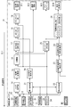
- FIG. 1A is a schematic block diagram showing a configuration of an information information system and a sensor system according to the first embodiment.
- FIG. 1B is a schematic diagram showing the configuration of an image sensor used in the same information processing system.
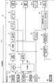
- FIG. 2 is a schematic block diagram showing the configuration of the same information processing system.
- FIG. 3 is a flowchart showing an operation example of the same information processing system.
- FIG. 4 is an explanatory diagram showing an outline of the operation of the same information processing system in the parking space detection mode.
- FIG. 5 is an explanatory diagram schematically showing an information processing result in the parking space detection mode of the same information processing system.
- FIG. 6 is an explanatory diagram showing an outline of the operation of the same information processing system in the object detection mode.
- FIG. 1A is a schematic block diagram showing a configuration of an information information system and a sensor system according to the first embodiment.
- FIG. 1B is a schematic diagram showing the configuration of an image sensor used in the same information processing system.
- FIG. 2 is
- FIG. 7 is an explanatory diagram schematically showing the information processing result in the object detection mode of the same information processing system.
- FIG. 8A is an explanatory diagram showing a situation in which the same information processing system is used.
- FIG. 8B is an explanatory diagram schematically showing how the detection result of the three-dimensional object detection process is corrected by the fusion process of the same information processing system.
- FIG. 9 is a schematic block diagram showing a configuration of an information processing system according to a third modification of the first embodiment.
- FIG. 10 is a schematic block diagram showing a configuration of an information processing system according to a fourth modification of the first embodiment.
- FIG. 11 is a schematic block diagram showing a configuration of an information processing system according to a fifth modification of the first embodiment.
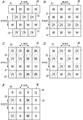
- FIG. 12A to 12E are schematic views showing the configuration of the image sensor according to the modified example of the first embodiment.
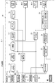
- FIG. 13 is a schematic block diagram showing the configuration of the information processing system according to the second embodiment.
- FIG. 14 is a schematic block diagram showing a configuration of an information processing system according to a modified example of the second embodiment.
- the information processing system 1 is a system used for the image sensor 3.
- the image sensor 3 has a plurality of pixels, forms an image of light from an object through an optical system on a light receiving surface on which the plurality of pixels are arranged, and photoelectrically converts the light and darkness of the light into an amount of electric charge. It is an element that outputs as an electric signal by reading this.
- the image sensor 3 is a solid-state image sensor using a semiconductor element.
- the image sensor 3 has a first pixel 31 and a second pixel 32.
- the first pixel 31 is sensitive to visible light.
- the second pixel 32 is sensitive to infrared light.
- the information processing system 1 executes various processes on the information acquired from such an image sensor 3. As a result, the information processing system 1 can obtain information processing results regarding the status of the monitoring area A1 (see FIG. 4) within the angle of view of the image sensor 3.
- the "information processing result" referred to in the present disclosure is the result of information processing obtained by the information processing system 1, and as an example, is information regarding the presence or absence of an object Ob1 (see FIG. 4) in the monitoring area A1.
- the information processing system 1 includes a first acquisition unit 11, a second acquisition unit 12, and a third acquisition unit 13.
- the first acquisition unit 11 acquires the first luminance information D1 from the first pixel 31.
- the first luminance information D1 is information regarding the pixel value of the first pixel 31.
- the second acquisition unit 12 acquires the second luminance information D2 from the second pixel 32.
- the second luminance information D2 is information regarding the pixel value of the second pixel 32.
- the third acquisition unit 13 acquires the distance information D3 from the second pixel 32.
- the distance information D3 is information related to the distance from the image sensor 3 to the object Ob1 (see FIG. 4) that reflects infrared light.
- first luminance information D1 first
- first luminance information D2 first
- first luminance information D3 first luminance information D2
- distance information D3 are different from each other, but have a correlation with each other because they are obtained from one image sensor 3.
- second luminance information D2 and the distance information D3 are both acquired from the second pixel 32, there is a strong correlation between the second luminance information D2 and the distance information D3.
- the information processing system 1 it is possible to obtain various information regarding the status of the monitoring area A1 within the angle of view of the image sensor 3 with relatively high accuracy from these three types of information. As a result, it is possible to improve the accuracy of information processing in the information processing system 1.
- the information processing system 1 and the sensor system 10 are mounted on a moving body such as an automobile.
- the moving body is a car driven by a person.
- the information processing system 1 and the sensor system 10 are used, for example, in an advanced driver assistance system (ADAS) for a moving body, an automatic driving technology, a driver monitoring technology, and the like.
- ADAS advanced driver assistance system
- the advanced driver assistance system or the automatic driving technology it is possible to detect the existence of the object Ob1 around the moving body by recognizing the monitoring area A1 around the moving body in the information processing system 1. is there.
- a person including a pedestrian, a standing person, a sitting person, a person riding a bicycle, etc.
- a living thing such as a small animal
- There are other moving bodies, walls, guardrails and structures such as traffic lights.
- the information processing system 1 basically obtains information on the status of the monitoring area A1 around the moving body as the information processing result.
- the information processing result includes information on the presence / absence of an object Ob1 in the monitoring area A1 around the moving body, information on the position of the object Ob1 existing in the monitoring area A1 in the monitoring area A1, and information on the attributes of the object Ob1. Contains one or more pieces of information selected from the group consisting of.
- “Visible light” as used in the present disclosure means an electromagnetic wave having a wavelength visible to the human eye, that is, visible light.
- the lower limit of the wavelength of visible light is in the range of approximately 360 nm or more and 400 nm or less.
- the upper limit of the wavelength of visible light is in the range of approximately 760 nm or more and 830 nm or less.
- the first pixel 31 of the image sensor 3 has sensitivity for light (visible light) in such a wavelength range. In the present embodiment, as an example, it is assumed that the first pixel 31 has sensitivity in substantially the entire wavelength range of visible light.
- the "infrared light” referred to in the present disclosure means an electromagnetic wave having a wavelength longer than that of red visible light and a wavelength shorter than that of radio waves, that is, infrared light. Therefore, the lower limit of the wavelength of infrared light is in the range of about 760 nm or more and 830 nm or less.
- the upper limit of the wavelength of infrared light is in the range of approximately 2.5 ⁇ m (near infrared) or more and 4.0 ⁇ m (mid infrared) or less.
- the second pixel 32 of the image sensor 3 has sensitivity for light (infrared light) in such a wavelength range. In the present embodiment, as an example, it is assumed that the second pixel 32 has a sensitivity near the center wavelength of the output light of the light emitting unit 4 described later.
- the "image” referred to in the present disclosure includes a moving image (moving image) and a still image (still image).
- the "moving image” includes an image composed of a plurality of still images obtained by time-lapse photography or the like.
- the image is a still image.
- the information processing system 1 is connected to the control system 2 as shown in FIG. 1A.
- the control system 2 is a system that operates by receiving an output signal from the information processing system 1.
- the output signal from the information processing system 1 includes at least the information processing result obtained by the information processing system 1, that is, the information processing result.
- the control system 2 is a system that operates by receiving an output signal from the information processing system 1. Since the output signal from the information processing system 1 includes the information processing result as described above, the control system 2 can operate according to the information processing result. As an example, the control system 2 presents information to the driver of the moving body as appropriate, such as displaying information for supporting the driving of the moving body on a display device according to the information processing result from the information processing system 1. I do. Further, the control system 2 may support the operation (steering) of the moving body by controlling the steering or braking of the moving body according to the information processing result from the information processing system 1.
- the information processing system 1 constitutes a sensor system 10 together with an image sensor 3, a light emitting unit 4 and a signal processing unit 5.
- the sensor system 10 according to the present embodiment includes an information processing system 1 and an image sensor 3.
- the sensor system 10 further includes a light emitting unit 4 and a signal processing unit 5 in addition to the information processing system 1 and the image sensor 3.
- the information processing system 1, the image sensor 3, the light emitting unit 4, and the signal processing unit 5 constituting the sensor system 10 are all mounted on the moving body.
- the control system 2 connected to the sensor system 10 is also mounted on the moving body as an example.
- control system 2 is not included in the components of the sensor system 10, but the control system 2 may be included in the components of the sensor system 10.
- the light emitting unit 4 and the signal processing unit 5 are included in the components of the sensor system 10, but the sensor system 10 includes at least one of the light emitting unit 4 and the signal processing unit 5 as a component. It does not have to be included.
- the image sensor 3 and the light emitting unit 4 are connected to the information processing system 1 via the signal processing unit 5.
- the image sensor 3 and the light emitting unit 4 are both connected to the signal processing unit 5, and the signal processing unit 5 is connected to the information processing system 1.
- the signal processing unit 5 reads an electric signal from the image sensor 3 and performs various signal processing such as filtering on the read electric signal.
- the signal processing unit 5 has a function of controlling the light emitting unit 4, and causes the light emitting unit 4 to emit light at an arbitrary timing.
- the signal processing unit 5 generates the first luminance information D1, the second luminance information D2, and the distance information D3 based on the electric signal read from the image sensor 3.
- the first luminance information D1 is information regarding the pixel value of the first pixel 31, and is generated from an electric signal read from the first pixel 31.
- the second luminance information D2 is information regarding the pixel value of the second pixel 32, and is generated from the electric signal read from the second pixel 32.
- the distance information D3 is information on the distance from the image sensor 3 to the object Ob1 that reflects infrared light, and is generated from an electric signal read from the second pixel 32.
- the information processing system 1 is connected to the image sensor 3 via the signal processing unit 5, and the signal processing unit also includes the first luminance information D1, the second luminance information D2, and the distance information D3. Obtained from the image sensor 3 via 5.
- the information processing system 1 does not directly acquire the first luminance information D1 from the first pixel 31 of the image sensor 3, but indirectly through the signal processing unit 5 to obtain the first luminance information D1.
- the first luminance information D1 is acquired from the pixel 31.
- the information processing system 1 does not directly acquire the second luminance information D2 from the second pixel 32 of the image sensor 3, but indirectly from the second pixel 32 to the second via the signal processing unit 5. 2 Acquire the brightness information D2.
- the information processing system 1 does not directly acquire the distance information D3 from the second pixel 32 of the image sensor 3, but indirectly from the second pixel 32 via the signal processing unit 5. To get.
- the image sensor 3 has a plurality of pixels including a plurality of first pixels 31 and a plurality of second pixels 32 in the row direction (longitudinal direction) and the column direction (vertical direction) of the light receiving surface. It is arranged two-dimensionally so that it is lined up in both directions (horizontally).
- FIG. 1B is a schematic diagram for showing an arrangement of a plurality of first pixels 31 and a plurality of second pixels 32, and in reality, a large number of first pixels 31 and a large number of second pixels 32 are image sensors. It may be lined up on the light receiving surface of 3.
- FIG. 1B is a schematic diagram for showing an arrangement of a plurality of first pixels 31 and a plurality of second pixels 32, and in reality, a large number of first pixels 31 and a large number of second pixels 32 are image sensors. It may be lined up on the light receiving surface of 3.
- FIG. 1B is a schematic diagram for showing an arrangement of a plurality of first pixels 31 and a plurality of second pixels 32,
- 16 pixels (8 first pixels 31 and 8 second pixels 32) are arranged side by side in the row direction and the column direction of the light receiving surface, respectively.
- the first pixel 31 having sensitivity to visible light is given the letter “W” to mean “white”
- the second pixel 32 having sensitivity to infrared light is given “infrared” to mean “infrared”.
- the letters "IR" are attached.
- the first brightness information D1 acquired by the information processing system 1 from the image sensor 3 via the signal processing unit 5 is obtained from the plurality of first pixels 31. It constitutes an image (brightness image) that is a set of outputs.
- the second brightness information D2 acquired by the information processing system 1 from the image sensor 3 via the signal processing unit 5 is obtained from the plurality of second pixels 32. It constitutes an image (brightness image) that is a set of outputs.
- the distance information D3 acquired by the information processing system 1 from the image sensor 3 via the signal processing unit 5 is a set of outputs of the plurality of second pixels 32.
- An image (distance image) is constructed.
- a plurality of first pixels 31 and a plurality of second pixels 32 are arranged in the column direction of the light receiving surface of the image sensor 3, and the first pixel 31 and the second pixel 32 are arranged in the row direction of the light receiving surface. They are arranged so that they are lined up alternately. That is, the plurality of first pixels 31 form a first pixel row arranged in the row direction of the light receiving surface, and the plurality of second pixels 32 form a second pixel row arranged in the row direction of the light receiving surface. The first pixel row and the second pixel row are alternately arranged in the row direction of the light receiving surface. According to such an arrangement, the plurality of first pixels 31 and the plurality of second pixels 32 can each realize relatively high resolution in the row direction of the light receiving surface.
- the first pixel 31 has sensitivity in substantially the entire wavelength range of such visible light. Therefore, as long as the first pixel 31 is in the wavelength range of visible light, basically, no matter which color of light is input, an output corresponding to the intensity of the light is generated. That is, the first luminance information D1 output from the first pixel 31 is light / dark information representing the intensity of the light input to the first pixel 31.
- the number of first pixels 31 (number of pixels) and the number of second pixels 32 (number of pixels) in the image sensor 3 are the same.
- the number of first pixels 31 (number of pixels) and the number of second pixels 32 (number of pixels) in the image sensor 3 may be different.
- an infrared cut filter that shields infrared light is arranged on the front surface of the first pixel 31.
- the infrared cut filter is not an essential configuration and can be omitted as appropriate.
- the light emitting unit 4 is arranged together with the image sensor 3 toward the monitoring area A1.
- the light emitting unit 4 outputs light toward at least the monitoring area A1.
- the light emitting unit 4 outputs light in a wavelength range in which at least the second pixel 32 of the image sensor 3 has sensitivity, that is, infrared light.
- an element such as a light emitting diode (LED: Light Emitting Diode) or a laser diode, which has a relatively high response speed and is capable of high-speed modulation (high-speed blinking), is used.
- information (distance information D3) regarding the distance to the object Ob1 existing in the monitoring area A1 can be obtained by the ToF (Time-of-Flight) method. Be done. That is, the time from when the light emitting unit 4 emits light until the output light of the light emitting unit 4 is reflected by the object Ob1 and received by the second pixel 32 of the image sensor 3 is the distance from the image sensor 3 to the object Ob1. It changes according to. Utilizing this fact, it is possible to measure the distance to the object Ob1 that reflects the light by measuring the flight time of the light (infrared light in this case).
- the signal processing unit 5 monitors the intensity-modulated light (hereinafter, also referred to as “intensity-modulated light”) from the light emitting unit 4. Output to A1. Then, the signal processing unit 5 measures the time using the phase difference between the phase of the intensity change at the time of light reception by the image sensor 3 and the phase of the intensity change at the time of projecting from the light emitting unit 4. If the frequency of the intensity change in the intensity-modulated light is constant, the phase difference is converted into the distance to the object Ob1 by a relatively simple calculation.
- the intensity-modulated light whose intensity changes is projected from the light emitting unit 4 to the monitoring area A1 and the intensity of the light received by one second pixel 32 of the image sensor 3 changes. Since the time difference of the same phase reflects the distance to the object Ob1, if the speed of light is c [m / s] and the time difference ⁇ t [s] is used, the distance L to the object Ob1 is expressed by the following equation 1. To.
- the light receiving intensity may be obtained for each of the second pixels 32 of the image sensor 3 for a plurality of different phases of the modulated signal.
- the amount of received light in each phase section having a predetermined phase width (time width) is detected, and the received output corresponding to this amount of received light is calculated for the phase difference ⁇ .
- the phase intervals are 90 degree intervals, four phase intervals having the same phase interval for one period of the modulated signal can be obtained periodically.
- the amount of received light for each phase section is C0 to C3
- the phase difference ⁇ is expressed by the following equation 3.
- phase difference ⁇ tan -1 ⁇ (C0-C2) / (C1-C3) ⁇ (Equation 3)
- the sign of the phase difference ⁇ changes depending on which phase of the modulated signal the received light amounts C0 to C3 correspond to, but the phase difference ⁇ may use an absolute value.
- the signal processing unit 5 drives the light emitting unit 4 by giving a modulated signal to the light emitting unit 4 so that the intensity-modulated light as described above is projected.
- a light receiving output corresponding to the received light amounts C0 to C3 for each of the four phase sections is obtained from the image sensor 3, and the light receiving output (electric signal) of the image sensor 3 is input to the signal processing unit 5.
- the signal processing unit 5 performs an operation to obtain the distance to the object Ob1 using the light receiving output. At this time, the signal processing unit 5 gives the image sensor 3 a read signal generated based on the reference signal synchronized with the modulated signal, and reads the received light output.
- the information processing system 1 has various functions in addition to the first acquisition unit 11, the second acquisition unit 12, and the third acquisition unit 13. That is, as shown in FIG. 2, the information processing system 1 further includes a noise processing unit 14, a coordinate conversion unit 15, a separation unit 16, a three-dimensional object detection unit 17, a fusion unit 18, and a tracking unit 19. Further, the information processing system 1 includes a two-dimensional object detection unit 20, a first synthesis unit 21, a second synthesis unit 22, a white line candidate area detection unit 23, a white line candidate area bird's-eye view conversion unit 24, a free space detection unit 25, and a parking frame. It further includes a detection unit 26 and an output unit 27.
- the information processing system 1 mainly includes a computer system (including a server and cloud computing) having one or more processors and one or more memories.
- the processor realizes the function of the information processing system 1 by executing the program recorded in the memory.
- the program may be pre-recorded in memory, provided by being recorded on a non-temporary recording medium such as a memory card, or provided through a telecommunication line.
- the above program is a program for making one or more processors function as the information processing system 1.
- odometry information D4 (denoted as “Odometry” in the figure) and confidence information D5 (denoted as “Conf” in the figure) are further input to the information processing system 1. That is, a total of five types of data (information) of the first brightness information D1, the second brightness information D2, the distance information D3, the odometry information D4, and the confidence information D5 are input to the information processing system 1.
- the odometry information D4 includes, for example, the tilt angle of the moving body, the traveling direction of the moving body, the moving speed of the moving body, the acceleration applied to the moving body, the accelerator pedal depression amount (accelerator opening), the brake pedal depression amount or the steering angle.
- Etc. which includes information that can be detected by a sensor mounted on a moving body.
- the odometry information D4 is information based on the current position of the moving body that can be detected using GPS (Global Positioning System) or the like, and is, for example, the number of lanes on the road at the current position, the distinction between white and yellow lines, and the roadway. Includes width, presence or absence of sidewalks, slope or curve curvature, etc.
- Confidence information D5 is information related to the reliability of data. As an example, the confidence information D5 is used to determine whether or not the distance information D3 corresponds to pseudo-distance information affected by interference, multipath, or the like. Similarly, the confidence information D5 is used to determine whether or not the first luminance information D1 or the second luminance information D2 corresponds to pseudo-luminance information.
- the first acquisition unit 11 is connected to the signal processing unit 5. That is, the first acquisition unit 11 is connected to the first pixel 31 of the image sensor 3 via the signal processing unit 5. As described above, the first acquisition unit 11 acquires the first luminance information D1 regarding the pixel value of the first pixel 31 from the first pixel 31. In the present embodiment, the first acquisition unit 11 indirectly acquires the first luminance information D1 from the first pixel 31 via the signal processing unit 5.
- the second acquisition unit 12 is connected to the signal processing unit 5. That is, the second acquisition unit 12 is connected to the second pixel 32 of the image sensor 3 via the signal processing unit 5. As described above, the second acquisition unit 12 acquires the second luminance information D2 regarding the pixel value of the second pixel 32 from the second pixel 32. In the present embodiment, the second acquisition unit 12 indirectly acquires the second luminance information D2 from the second pixel 32 via the signal processing unit 5.
- the third acquisition unit 13 is connected to the signal processing unit 5. That is, the third acquisition unit 13 is connected to the second pixel 32 of the image sensor 3 via the signal processing unit 5. As described above, the third acquisition unit 13 acquires the distance information D3 regarding the distance from the image sensor 3 to the object Ob1 that reflects infrared light from the second pixel 32. In the present embodiment, the third acquisition unit 13 indirectly acquires the distance information D3 from the second pixel 32 via the signal processing unit 5.
- the noise processing unit 14 corrects the distance information D3 by using the distance information D3 and one or more information selected from the group consisting of the first luminance information D1 and the second luminance information D2.
- One or more information selected from the group consisting of the first luminance information D1 and the second luminance information D2 includes the first luminance information D1, the second luminance information D2, the first luminance information D1 and the second luminance information D2. It is one of the combined luminance information (hereinafter, also referred to as “composite image”).
- the noise processing unit 14 is connected to the third acquisition unit 13. In the present embodiment, the noise processing unit 14 is connected to the second acquisition unit 12 via the first synthesis unit 21.
- the first luminance information D1 or the second luminance information D2 is not directly input to the noise processing unit 14, but is indirectly input via the first combining unit 21. Since the distance information D3 alone has a relatively low SN ratio and a large noise ratio, the noise processing unit 14 reduces the noise of the distance information D3. The operation of the noise processing unit 14 will be described in detail in the column of "(3) Operation".
- the coordinate conversion unit 15 is provided after the noise processing unit 14.
- the coordinate conversion unit 15 performs coordinate conversion processing on the (noise-reduced) distance information D3 in the Cartesian coordinate system of X, Y, and Z. Specifically, the coordinate conversion unit 15 generates a point cloud (point cloud data) having coordinate values of X, Y, and Z based on the distance information D3.
- the separation unit 16 separates the object Ob1 and the peripheral region located around the object Ob1.
- the "peripheral area" referred to in the present disclosure is, for example, a road surface, a ground surface, a floor surface, or the like that is excluded from the detection target when detecting the presence or absence of the object Ob1.
- the separation unit 16 separates a region other than the road surface or the like including the object Ob1 from a peripheral region such as the road surface.
- the separation unit 16 separates the object Ob1 and the peripheral region of the distance information D3 (point cloud) after the coordinate conversion input from the coordinate conversion unit 15.
- the separation unit 16 first extracts a component corresponding to the peripheral region from the distance information D3 after the coordinate conversion input from the coordinate conversion unit 15.
- the separation unit 16 removes the extracted peripheral region from the distance information D3 after the coordinate conversion, and outputs the component corresponding to the object Ob1 in the distance information D3 to the three-dimensional object detection unit 17 in the subsequent stage. ..
- the peripheral region is all regions other than the object Ob1 in the distance information D3, and includes not only the region near the object Ob1 but also the region far away from the object Ob1.
- the separation unit 16 outputs the information regarding the separated peripheral region to the output unit 27 as the road surface information D12.
- odometry information D4 is also input to the separation unit 16. The operation of the separation unit 16 will be described in detail in the column of "(3) Operation".
- the three-dimensional object detection unit 17 detects the object Ob1 based on the distance information D3.
- the distance information D3 in the state where the peripheral region is removed is input to the three-dimensional object detection unit 17 from the separation unit 16.
- the three-dimensional object detection unit 17 detects the object Ob1 in the monitoring area A1 by using the distance information D3 input from the separation unit 16, and when it is determined that the object Ob1 exists, the distance information D3 corresponding to the object Ob1. (Point cloud) is output as a "target".
- the three-dimensional object detection unit 17 detects the object Ob1 based on one or more information selected from the group consisting of the first luminance information D1 and the second luminance information D2 in addition to the distance information D3. I do. That is, there is a noise processing unit 14 in front of the three-dimensional object detection unit 17, and the noise processing unit 14 selects one or more from the group consisting of the first luminance information D1 and the second luminance information D2 as described above.
- the distance information D3 is corrected by indirectly using the information of. Therefore, the three-dimensional object detection unit 17 indirectly uses not only the distance information D3 but also one or more information selected from the group consisting of the first luminance information D1 and the second luminance information D2 to indirectly use the object Ob1. It will be detected.
- the three-dimensional object detection unit 17 may detect the object Ob1 based on the first luminance information D1 corrected according to the timing of the second luminance information D2 in addition to the distance information D3. In this case, the three-dimensional object detection unit 17 does not directly use the second luminance information D2, but uses the first luminance information D1 corrected to match the timing of the second luminance information D2, and uses the object Ob1. Will be detected. The operation of the three-dimensional object detection unit 17 will be described in detail in the column of "(3) Operation".
- the fusion unit 18 synthesizes the detection result of the two-dimensional object detection unit 20 and the detection result of the three-dimensional object detection unit 17.
- the three-dimensional object detection unit 17 and the two-dimensional object detection unit 20 are arranged in front of the fusion unit 18, and the fusion unit 18 contains the detection result of the three-dimensional object detection unit 17 and the two-dimensional object detection unit 17.
- the detection result of the object detection unit 20 is input.
- the detection result of the three-dimensional object detection unit 17 corresponds to at least the detection result of the object Ob1 based on the distance information D3, that is, the three-dimensional detection result of the object Ob1.
- the detection result of the two-dimensional object detection unit 20 is the detection result of the object Ob1 based on one or more information selected from the group consisting of the first luminance information D1 and the second luminance information D2, that is, the two-dimensional detection result of the object Ob1.
- the fusion unit 18 does not directly synthesize one or more information selected from the group consisting of the first luminance information D1 and the second luminance information D2 and the distance information D3, but rather the first luminance information D1 and
- the detection result of the object Ob1 based on each of one or more information selected from the group consisting of the second luminance information D2 and the distance information D3 is synthesized.
- the fusion unit 18 indirectly synthesizes one or more information selected from the group consisting of the first luminance information D1 and the second luminance information D2 and the distance information D3.
- the object Ob1 is detected in the front stage of the fusion unit 18, and the fusion unit 18 includes the first luminance information D1 and the second luminance information D2 based on the detection result of the object Ob1.
- the distance information D3 is combined with one or more pieces of information selected from the group.
- the "detection result of the object Ob1" here means the detection results of both the three-dimensional object detection unit 17 and the two-dimensional object detection unit 20. More specifically, the fusion unit 18 uses the detection result of the object Ob1 based on one or more information selected from the group consisting of the first luminance information D1 and the second luminance information D2, and uses the detection result of the object Ob1 based on the distance information D3. Change the detection result of.
- the fusion unit 18 corrects the detection result (three-dimensional detection result) of the three-dimensional object detection unit 17 by using the detection result (two-dimensional detection result) of the two-dimensional object detection unit 20. As a result, the fusion unit 18 synthesizes the two-dimensional detection result and the three-dimensional detection result.
- the fusion unit 18 corrects the detection result of the three-dimensional object detection unit 17 by synthesizing one or more information selected from the group consisting of the first luminance information D1 and the second luminance information D2 and the distance information D3.
- the corrected detection result of the three-dimensional object detection unit 17 is output to the tracking unit 19.
- the operation of the fusion unit 18 will be described in detail in the column of "(3) Operation".
- the fusion unit 18 outputs the feedback signal Si1 to the sensor system 10 including the image sensor 3.
- the image sensor 3 outputs an electric signal in which one or more parameters selected from the group consisting of the exposure time and the frame rate are changed by the feedback signal Si1. That is, the feedback signal Si1 output by the fusion unit 18 is fed back to the sensor system 10 as shown in FIGS. 1A and 2.
- the feedback signal Si1 includes the detection result of the corrected three-dimensional object detection unit 17, which is the output of the fusion unit 18.
- the image sensor 3 outputs an electric signal in which the exposure time and / or the frame rate is changed according to the feedback signal Si1.
- the tracking unit 19 tracks the object Ob1 existing in the monitoring area A1.
- the tracking unit 19 tracks the object Ob1 by comparing the detection result (target) of the corrected three-dimensional object detection unit 17 input from the fusion unit 18 among a plurality of frames of the output of the image sensor 3, for example. I do.
- the tracking unit 19 can recognize the object Ob1 before the movement and the object Ob1 after the movement as the same object even when the object Ob1 moves in the monitoring area A1.
- the tracking result of the tracking unit 19 is output to the output unit 27 as the target information D11.
- odometry information D4 is also input to the tracking unit 19.
- the two-dimensional object detection unit 20 detects the object Ob1 based on one or more information selected from the group consisting of the first luminance information D1 and the second luminance information D2.
- the two-dimensional object detection unit 20 is connected to the first acquisition unit 11 via the first synthesis unit 21.
- the second acquisition unit 12 is also connected to the first synthesis unit 21
- the two-dimensional object detection unit 20 is also connected to the second acquisition unit 12 via the first synthesis unit 21.
- the first luminance information D1 or the second luminance information D2 is not directly input to the two-dimensional object detection unit 20, but is indirectly input via the first synthesis unit 21.
- the two-dimensional object detection unit 20 Since the output of the first synthesis unit 21 reflects one or more information selected from the group consisting of the first luminance information D1 and the second luminance information D2, the two-dimensional object detection unit 20 has the first luminance information.
- the object Ob1 is detected by indirectly using the D1 or the second luminance information D2.
- the two-dimensional object detection unit 20 uses one or more information selected from the group consisting of the first luminance information D1 and the second luminance information D2 input from the first synthesis unit 21, and the object Ob1 in the monitoring area A1. Is detected and it is determined that the object Ob1 exists, one or more information selected from the group consisting of the first luminance information D1 and the second luminance information D2 with the marker M1 (see FIG. 7) corresponding to the object Ob1. Is output.
- the two-dimensional object detection unit 20 detects the object Ob1 based on one or more information selected from the group consisting of the first luminance information D1 and the second luminance information D2. That is, the first synthesis unit 21 is in front of the two-dimensional object detection unit 20, and the first synthesis unit 21 synthesizes the first luminance information D1 and the second luminance information D2. Therefore, the two-dimensional object detection unit 20 indirectly uses a composite image in which not only the first luminance information D1 or the second luminance information D2 but also the first luminance information D1 and the second luminance information D2 are combined to form the object Ob1. Can be detected.
- the operation of the two-dimensional object detection unit 20 will be described in detail in the column of "(3) Operation".
- the first synthesis unit 21 is connected to the first acquisition unit 11 and the second acquisition unit 12.
- the first combining unit 21 synthesizes the first luminance information D1 and the second luminance information D2.
- a composite image is generated by synthesizing the first luminance information D1 and the second luminance information D2.
- the "composite" referred to in the present disclosure includes weighted compositing. For example, if the weighting coefficients of the first luminance information D1 and the second luminance information D2 are "1: 0", the composite image is the first compositing unit.
- the first luminance information D1 is output as it is from 21.
- the first synthesizer 21 includes a function as a selector that selectively outputs the first luminance information D1 and the second luminance information D2.
- the first luminance information D1 and the second luminance information D2 synthesized by the first combining unit 21 are input to the noise processing unit 14 and the two-dimensional object detecting unit 20.
- the first synthesis unit 21 is appropriately controlled so that the output of the first synthesis unit 21 becomes a composite image suitable for the operation of the noise processing unit 14 and the two-dimensional object detection unit 20. Further, the composite image input from the first composite unit 21 is composited by appropriately changing the weighting coefficient according to the situation of the monitoring area A1 such as daytime / nighttime or weather (rain, fog). Is preferable.
- the second synthesis unit 22 is connected to the first acquisition unit 11 and the second acquisition unit 12.
- the second combining unit 22 synthesizes the first luminance information D1 and the second luminance information D2. Similar to the first synthesis unit 21, the second synthesis unit 22 also includes a function as a selector that selectively outputs the first luminance information D1 and the second luminance information D2.
- the first luminance information D1 and the second luminance information D2 synthesized by the second combining unit 22 are input to the white line candidate region detecting unit 23. Therefore, it is preferable that the second synthesis unit 22 is appropriately controlled so that the output of the second synthesis unit 22 becomes a composite image suitable for the operation of the white line candidate region detection unit 23. Further, the composite image input from the second composite unit 22 is composited by appropriately changing the weighting coefficient according to the situation of the monitoring region A1 such as daytime / nighttime or weather (rain, fog). Is preferable.
- the output of the first synthesis unit 21 is input to the two-dimensional object detection unit 20, and the output of the second synthesis unit 22 is input to the white line candidate region detection unit 23.
- the weight coefficients at the time of synthesis are different between the first synthesis unit 21 and the second synthesis unit 22. ..
- the first synthesis unit 21 and the second synthesis unit 22 both function as a "synthesis unit” that synthesizes the first luminance information D1 and the second luminance information D2.
- the compositing unit (first compositing unit 21 and second compositing unit 22) synthesizes the first luminance information D1 and the second luminance information D2 so as to correct the information regarding the positions of the first pixel 31 and the second pixel 32.
- the synthesizing unit changes the weighting coefficient for synthesizing the first luminance information D1 and the second luminance information D2 according to the input reference information D6. That is, the reference information D6 is information on the situation of the monitoring area A1 such as daytime / nighttime or weather (rain, fog), and includes, for example, information on the illuminance and / or humidity around the object Ob1. There is.
- the white line candidate area detection unit 23 detects a candidate area of the white line 62 (see FIG. 4) drawn on the road surface 61 (see FIG. 4).
- the white line candidate region detection unit 23 detects the candidate region of the white line 62 based on the composite image of the first luminance information D1 and the second luminance information D2 input from the second composite unit 22. Confidence information D5 is also input to the white line candidate region detection unit 23.
- the detection of the white line 62 is, as an example, a portion where the pixel value (brightness) suddenly changes by performing edge extraction or the like using a filter on the composite image of the first luminance information D1 and the second luminance information D2. It is realized by detecting.
- the white line 62 to be detected by the white line candidate region detection unit 23 is not limited to the white line, and may be, for example, a yellow line (yellow line), a picture, a pattern, or the like.
- the white line candidate area bird's-eye view conversion unit 24 is provided after the white line candidate area detection unit 23.
- the bird's-eye view conversion unit 24 of the white line candidate area viewed at least the candidate area of the white line 62 detected by the white line candidate area detection unit 23 and its periphery from directly above the composite image of the first luminance information D1 and the second luminance information D2. Coordinate conversion is performed so that the image becomes a bird's-eye view.
- the free space detection unit 25 detects the free space in the monitoring area A1 based on the distance information D3, that is, the vacant space.
- the distance information D3 separated into the object Ob1 and the peripheral region located around the object Ob1 is input to the free space detection unit 25 from the separation unit 16.
- the free space detection unit 25 detects the free space in the monitoring area A1 by using the distance information D3 input from the separation unit 16.
- the detection result of the free space detection unit 25 is output to the output unit 27 as free space information D13 (denoted as "free space” in the figure).
- odometry information D4 is also input to the free space detection unit 25.
- the parking frame detection unit 26 detects an empty parking frame in the monitoring area A1, that is, an empty parking frame in which another vehicle is not parked.
- an empty parking frame in the monitoring area A1 that is, an empty parking frame in which another vehicle is not parked.
- multiple parking lots are provided, and parking lot users search for vacant parking lots and park vacantly. Park your vehicle (moving object) in the frame.
- the parking frame detection unit 26 in such a case, it is possible to automatically search for an empty parking frame.
- the detection result of the free space detection unit 25 and the output of the bird's-eye view conversion unit 24 of the white line candidate area (candidate area of the white line 62 after coordinate conversion) are input to the parking frame detection unit 26.
- the parking frame detection unit 26 performs pairing with the detection result of the free space detection unit 25 and the output of the bird's-eye view conversion unit 24 of the white line candidate area (candidate area of the white line 62 after coordinate conversion), and determines an empty parking frame. .. For example, the parking frame detection unit 26 determines that a parking frame having a size that allows a moving body to be parked in the monitoring area A1 and that partially overlaps with the fleece case is regarded as an empty parking frame. The detection result of the parking frame detection unit 26 is output to the output unit 27 as vacant parking frame information D14 (denoted as “vacant parking frame” in the figure).
- the output unit 27 outputs the information processing result regarding the status of the monitoring area A1 within the angle of view of the image sensor 3, which is performed based on the first luminance information D1, the second luminance information D2, and the distance information D3. That is, the information processing system 1 according to the present embodiment executes various information processing regarding the status of the monitoring area A1 based on the first luminance information D1, the second luminance information D2, and the distance information D3 acquired from the image sensor 3. Then, the result is output by the output unit 27.
- the output unit 27 obtains target information D11, road surface information D12, free space information D13 and, respectively, from the tracking unit 19, the separation unit 16, the free space detection unit 25, and the parking frame detection unit 26.
- the empty parking frame information D14 is output.
- the output unit 27 outputs this information to the control system 2.
- the information processing results include information on the presence or absence of the object Ob1 in the monitoring area A1 around the moving body, information on the position of the object Ob1 existing in the monitoring area A1 in the monitoring area A1, and the object Ob1. Contains information about the attribute and at least one of them.
- the target information D11 includes information on the presence / absence of the object Ob1 in the monitoring area A1 around the moving body, information on the position of the object Ob1 existing in the monitoring area A1 in the monitoring area A1, and the object Ob1. Includes all information about the attributes of.
- the “attribute” referred to in the present disclosure includes, for example, the type of the object Ob1, that is, whether it is a person or not, whether it is a moving body (person, automobile, bicycle, etc.) or a fixed object, or a roadside tree, a traffic light, a guardrail, etc. .. Further, the “attribute” of the object Ob1 also includes the size, color or movement (change) of the object Ob1. Further, if the object Ob1 is a person, its gender, height, body shape, age group, etc., and if the object Ob1 is a moving body, its moving direction or moving speed, etc. are also included in the "attribute" of the object Ob1.
- the information output by the output unit 27 changes as appropriate according to the request of the output destination.
- the output unit 27 may output meta-meta-information. ..
- the information system 1 has a plurality of operation modes including at least a parking space detection mode and an object detection mode. Each of these plurality of operation modes can be individually enabled / disabled. For example, if the parking space detection mode is enabled and all other operation modes are disabled, the information processing system 1 has the parking space. Works only in detection mode.
- the parking space detection mode is an operation mode for detecting an empty parking frame, and in this operation mode, the above-mentioned empty parking frame information D14 is output from the output unit 27.
- the object detection mode is an operation mode for detecting the object Ob1 in the monitoring area A1, and in this operation mode, the target information D11 described above is output from the output unit 27.
- FIG. 3 is a flowchart showing an operation example of the information processing system 1 according to the present embodiment.
- the information processing system 1 has a first acquisition process (S1) for acquiring the first luminance information D1, a second acquisition process (S2) for acquiring the second luminance information D2, and distance information.
- the third acquisition process (S3) for acquiring D3 is executed.
- the information processing system 1 executes the first acquisition process, the second acquisition process, and the third acquisition process (S1 to S3) at any time in the first acquisition unit 11, the second acquisition unit 12, and the third acquisition unit 13. .
- the noise processing unit 14 uses the distance information D3 and one or more information selected from the group consisting of the first luminance information D1 and the second luminance information D2 to provide the distance information.
- D3 By correcting D3, noise removal processing for reducing the noise of the distance information D3 is executed (S4).
- the noise removal processing will be described in detail in the column of "(3.2) Noise removal processing".
- the information processing system 1 executes a separation process in the separation unit 16 to separate the object Ob1 and the peripheral region located around the object Ob1 with respect to the distance information D3 after the coordinate conversion (S5). ..
- the separation process will be described in detail in the column of "(3.3) Separation process".
- the information processing system 1 determines whether or not the object detection mode is valid (S6). If the object detection mode is enabled (S6: Yes), the information processing system 1 executes a series of processes (S7 to S11) for detecting the object Ob1. That is, the information processing system 1 executes a three-dimensional object detection process in which the three-dimensional object detection unit 17 detects the object Ob1 (S7), and the two-dimensional object detection unit 20 detects the object Ob1.
- the object detection process is executed (S8).
- the three-dimensional object detection process will be explained in detail in the column of "(3.4) Three-dimensional object detection process", and the two-dimensional object detection process will be explained in detail in the column of "(3.5) Two-dimensional object detection process". To do.
- the information processing system 1 determines the presence or absence of the object Ob1 from the result of the fusion process (S10). If the object Ob1 exists (S10: Yes), the information processing system 1 outputs the target information D11 by the output unit 27 (S11), and determines whether or not the parking space detection mode is valid (S12). If the object Ob1 does not exist (S10: Yes), the information processing system 1 shifts to the process S12 without outputting the target information D11.
- the information processing system 1 executes a series of processes (S13 to S16) for detecting an empty parking frame. That is, the information processing system 1 detects the white line 62 (candidate area) by the white line candidate area detection unit 23 (S13), and detects the free space by the free space detection unit 25 (S14). From these results, the information processing system 1 determines whether or not there is an empty parking frame in the monitoring area A1 by the parking frame detection unit 26 (S15).
- the information processing system 1 If there is an empty parking frame (S15: Yes), the information processing system 1 outputs the empty parking frame information D14 to the output unit 27 (S16), and ends the series of processing. If there is no vacant parking frame (S15: Yes), the information processing system 1 ends a series of processes without outputting the vacant parking frame information D14.
- the information processing system 1 skips a series of processes (S7 to S11) for detecting the object Ob1 and shifts to the process S12. If the parking space detection mode is invalid (S12: No), the information processing system 1 skips a series of processes (S13 to S16) for detecting an empty parking frame and ends the process.
- the information information system 1 repeatedly executes a series of processes S1 to S16 as described above.
- the flowchart of FIG. 3 is merely an example of the overall operation of the information processing system 1, and the processing may be omitted or added as appropriate, or the order of the processing may be changed as appropriate.
- the order of the processes S1 to S3 may be changed, and after the second luminance information D2 and the distance information D3 are acquired (S2, S3), the first luminance information D1 may be acquired (S1).
- FIG. 4 and 5 are explanatory views showing an outline of the operation of the information processing system 1 in the parking space detection mode.
- FIG. 4 shows a state in which the monitoring area A1 is photographed by the image sensor 3, and the first luminance information D1, the second luminance information D2, and the distance information D3 obtained from the output of the image sensor 3 are input to the information processing system 1. It is represented schematically.
- FIG. 5 schematically shows the information processing result in the information processing system 1 in the parking space detection mode, that is, the empty parking frame information D14.
- the plurality of parking frames include a parking frame in which another vehicle (object Ob1) is parked and a parking frame (empty parking frame) in which another vehicle (object Ob1) is not parked.
- the information processing system 1 acquires the first luminance information D1, the second luminance information D2, and the distance information D3 from the image sensor 3 (via the signal processing unit 5) as shown in FIG. ..
- the first luminance information D1 is light / dark information representing the intensity of light input to the plurality of first pixels 31, the image is apparently a relatively faithful reproduction of the monitoring region A1 in the real space.
- the second luminance information D2 is light / dark information indicating the intensity of infrared light output from the light emitting unit 4 and input to the plurality of second pixels 32, the object Ob1 having a relatively low reflectance to infrared light is used. The image is not sufficiently reproduced and the contrast is low as compared with the first luminance information D1.
- the distance information D3 is a distance image representing the flight distance of infrared light output from the light emitting unit 4 and input to the plurality of second pixels 32, that is, the distance from the image sensor 3 to the object Ob1, the distance information D3 is relative to the infrared light.
- the object Ob1 having a relatively low reflectance is not sufficiently reproduced.
- the information processing system 1 uses the first luminance information D1, the second luminance information D2, and the distance information D3 to execute a series of processes (S13 to S16) for detecting an empty parking frame as described above. ..
- a parking frame in which another vehicle (object Ob1) is not parked is detected as an empty parking frame, and empty parking frame information D14 is generated.
- the vacant parking frame information D14 includes at least information regarding the position of the vacant parking frame within the monitoring area A1.
- the control system 2 in which the empty parking frame information D14 is input from the information processing system 1 displays an image in which the empty parking frame information D14 is superimposed on the image of the monitoring area A1 as shown in FIG. It may be displayed on a display device. In this case, it is preferable that the image displayed on the display device is provided with a balloon (denoted as "Free Space" in FIG. 5) indicating that the empty parking frame information D14 points to the empty parking frame.
- a ring clasp 63 (see FIG. 4) is installed in the parking frame surrounded by a pair of white lines 62.
- the information processing system 1 recognizes the ring fastening 63 as the object Ob1. That is, in the present embodiment, in the separation process (S5), which is a pre-process of a series of processes (S13 to S16) for detecting an empty parking frame, the distance information D3 after coordinate conversion is the object Ob1 and the periphery. The area and is separated. Therefore, if the parking frame is vacant, the area of the road surface 61 surrounded by the white line 62 and the ring clasp 63 is detected as the vacant parking frame.
- FIG. 6 and 7 are explanatory views showing an outline of the operation of the information processing system 1 in the object detection mode.
- FIG. 6 schematically shows the state of the monitoring area A1.
- FIG. 7 schematically represents the information processing result in the information processing system 1 in the object detection mode, that is, the target information D11.
- a scene in which a moving body is stopped at an intersection is assumed, and a road surface 61 including a roadway 611 and a sidewalk 612, a pedestrian crossing 64, etc., and a pedestrian crossing 64 are provided in the monitoring area A1.
- a road surface 61 including a roadway 611 and a sidewalk 612, a pedestrian crossing 64, etc., and a pedestrian crossing 64 are provided in the monitoring area A1.
- the sidewalk 612 is higher than the roadway 611.
- the information processing system 1 acquires the first luminance information D1, the second luminance information D2, and the distance information D3 from the image sensor 3 (via the signal processing unit 5).
- the information processing system 1 uses the first luminance information D1, the second luminance information D2, and the distance information D3 to execute a series of processes (S7 to S11) for detecting the object Ob1 as described above.
- the target information D11 includes at least information regarding the position of the object Ob1 within the monitoring area A1.
- the target information D11 includes a frame-shaped marker M1 surrounding the object Ob1 and an image of the object Ob1 in the marker M1.
- the control system 2 in which the target information D11 is input from the information processing system 1 displays an image in which the target information D11 is superimposed on the image in the monitoring area A1 as shown in FIG. It may be displayed in.
- the image displayed on the display device is provided with a balloon (denoted as “Human” or “Tree” in FIG. 7) indicating the attribute of the object Ob1 indicated by the target information D11.
- the separation process (S5) which is a pre-process of a series of processes (S7 to S11) for detecting the object Ob1
- the distance information D3 after the coordinate conversion is the object Ob1 and the periphery.
- the information processing system 1 according to the present embodiment can recognize the step between the sidewalk 612, which is higher than the roadway 611, as the object Ob1. Therefore, it is also possible to detect a step on the road surface 61 (a step between the roadway 611 and the sidewalk 612) and separate only the roadway 611 as the road surface.
- the noise processing unit 14 uses one or more information selected from the group consisting of the first luminance information D1 and the second luminance information D2 input from the first combining section 21 to use the distance information D3.
- the distance information D3 is corrected so as to reduce the noise of. More specifically, when the second luminance information D2 or the composite image of the first luminance information D1 and the second luminance information D2 and the distance information D3 are used, the information obtained from the output of the second pixel 32 is obtained. Since it is used, it is possible to remove noise in the distance information D3 between the second luminance information D2 and the distance information D3 without considering the time.
- the pixels to which the information is output are the first pixel 31 and the second pixel 32, respectively, so that a time lag may occur.
- the noise of the distance information D3 is removed after correcting the time difference between the first luminance information D1 and the distance information D3 based on the predetermined offset value. Therefore, by using one or more information selected from the group consisting of the first luminance information D1 and the second luminance information D2, it is possible to correct the distance information D3 so as to reduce noise.
- the noise processing unit 14 is selected from the group consisting of the first luminance information D1 and the second luminance information D2 in order to determine a filter for removing the noise of the distance information D3 having a relatively low SN ratio.
- Use filter information of one or more pieces of information is a portion where the pixel value (brightness) suddenly changes by performing edge extraction using a filter or the like on the composite image input from the first synthesis unit 21. Is detected, and a region that is a candidate for the object Ob1 is extracted.
- the noise processing unit 14 determines a filter to be applied to the distance information D3 with reference to the region extracted from such a composite image.
- the noise processing unit 14 adopts points in which the distance variation is in the range of 1.0 [m] for the area where a person is estimated to exist from the composite image, and the points outside this range are error values. Filtering is performed.
- the accuracy of the filter is likely to be improved and the noise of the distance information D3 can be efficiently removed as compared with the case where the error value range is determined only from the distance information D3 and filtering is performed.
- the separation unit 16 separates the object Ob1 and the peripheral region located around the object Ob1 with respect to the distance information D3 (point cloud) after the coordinate conversion input from the coordinate conversion unit 15. Specifically, the separation unit 16 first determines a point at a predetermined height or less as a road surface 61, which is a peripheral region, based on the absolute height of the points (position of the Z coordinate). Then, the separation unit 16 performs clustering to group a plurality of points higher than a predetermined height and within a predetermined range, and obtains a "plane" including the plurality of points in the same group and its "normal". ..
- the separation unit 16 determines that the obtained "plane" is the road surface 61. ..
- the separation unit 16 can also obtain the inclination and unevenness of the road surface 61 by the inclination of the normal line with respect to the vertical direction (Z axis) for the distance information D3 determined to be the peripheral region.
- the separation unit 16 can output information on the peripheral region as the road surface information D12, including the inclination and unevenness of the road surface 61. That is, the road surface information D12 includes information regarding the inclination and / or unevenness of the road surface 61 included in the peripheral region.
- the three-dimensional object detection unit 17 detects the object Ob1 based on the distance information D3 input from the separation unit 16. In the present embodiment, the three-dimensional object detection unit 17 determines whether or not the distance information D3 (point cloud) in the state where the peripheral region is removed is the object Ob1. Specifically, the three-dimensional object detection unit 17 determines whether or not the object is Ob1 based on, for example, the density of points in the point cloud. That is, if the density of points in the point cloud is equal to or higher than the threshold value, the three-dimensional object detection unit 17 determines that the object Ob1 exists at a position corresponding to these points. On the other hand, if the density of points in the point cloud is less than the threshold value, the three-dimensional object detection unit 17 determines that the object Ob1 does not exist at the position corresponding to these points.
- the three-dimensional object detection unit 17 performs clustering for grouping a plurality of points within a predetermined range, and is based on the size (that is, area) of a "plane" including the plurality of points in the same group. Therefore, it may be determined whether or not the object is Ob1. In this case, if the area is equal to or larger than the threshold value, the three-dimensional object detection unit 17 determines that the object Ob1 exists at a position corresponding to these points. On the other hand, if the area is less than the threshold value, the three-dimensional object detection unit 17 determines that the object Ob1 does not exist at the position corresponding to these points.
- the noise removal processing in the previous stage of the three-dimensional object detection processing one or more information selected from the group consisting of the first luminance information D1 and the second luminance information D2 is used.
- the distance information D3 is corrected. Therefore, in the three-dimensional object detection process, not only the distance information D3 but also one or more information selected from the group consisting of the first luminance information D1 and the second luminance information D2 is indirectly used to detect the object Ob1. Will be done.
- the information regarding the position of the object Ob1 in the monitoring area A1 and the information regarding the attributes of the object Ob1 are also determined. That is, when the object Ob1 exists, its position and attributes are also determined by the three-dimensional object detection process.
- the attribute of the object Ob1 determined by the three-dimensional object detection process is only the size of the object Ob1.
- the two-dimensional object detection unit 20 is based on one or more information selected from the group consisting of the first luminance information D1 and the second luminance information D2 input from the first synthesis unit 21. Detects the object Ob1. Basically, the two-dimensional object detection unit 20 moves the templates of various objects Ob1 on the luminance image, and based on the similarity with the template of the partial image to be compared with the template, whether or not the object Ob1 is present. Make a decision. That is, if the degree of coincidence between the partial image and the template is equal to or greater than the threshold value, the two-dimensional object detection unit 20 determines that the object Ob1 exists at a position corresponding to the partial image. On the other hand, if the degree of coincidence between the partial image and the template is less than the threshold value, the two-dimensional object detection unit 20 determines that the object Ob1 does not exist at the position corresponding to the partial image.
- the two-dimensional object detection unit 20 uses, for example, a HOG (Histograms of Oriented Gradients) feature amount, a convolutional neural network (CNN), or the like from the first luminance information D1 and the second luminance information D2.
- the object Ob1 may be detected based on one or more pieces of information selected from the group.
- the information regarding the position of the object Ob1 in the monitoring area A1 and the information regarding the attributes of the object Ob1 are also determined. That is, when the object Ob1 exists, its position and attributes are also determined by the two-dimensional object detection process.
- the attributes of the object Ob1 determined by the two-dimensional object detection process include the size and type of the object Ob1.
- the object Ob1 is detected by a means different from the three-dimensional object detection process.
- the fusion unit 18 synthesizes the detection result of the two-dimensional object detection unit 20 and the detection result of the three-dimensional object detection unit 17. That is, the detection result of the three-dimensional object detection process is at least the detection result of the object Ob1 performed based on the distance information D3, and the detection result of the two-dimensional object detection process is at least the first luminance information D1 or the second luminance. It is a detection result of the object Ob1 performed based on the information D2.
- the three-dimensional object detection process detects the object Ob1 based on the distance information D3 generated when the infrared light output from the light emitting unit 4 is reflected by the object Ob1 and input to the second pixel 32. There is a possibility that the object Ob1 having a relatively low reflectance to external light cannot be detected. On the other hand, since the two-dimensional object detection process does not use the distance information D3, it is not possible to detect the three-dimensional object Ob1 that reflects the distance from the image sensor 3 to the object Ob1. In the fusion process, by synthesizing the detection results of both the three-dimensional object detection process and the two-dimensional object detection process, it is possible to obtain the detection result of the object Ob1 that compensates for each defect. That is, even if the object Ob1 has a relatively low reflectance to infrared light, it is possible to detect the three-dimensional object Ob1 that reflects the distance from the image sensor 3 to the object Ob1.
- the fusion unit 18 uses the detection result of the two-dimensional object detection process (the detection result of the object Ob1 based on the first luminance information D1 or the second luminance information D2), and the detection result of the three-dimensional object detection process. (Detection result of object Ob1 based on distance information D3) is corrected. For example, for an object Ob1 including a portion having a low reflectance to infrared light, a point corresponding to a part of the object Ob1 may be lost in the detection result (point cloud) of the three-dimensional object detection process. .. Therefore, in the fusion process, the detection result of the three-dimensional object detection process is corrected (complemented) by the detection result of the two-dimensional object detection process so as to complement the missing points.
- FIGS. 8A and 8B are explanatory views schematically showing how the detection result of the three-dimensional object detection process is corrected (complemented) by the fusion process.
- a road surface 61 and a person (object Ob1) exist in the monitoring area A1.
- the reflectance of the jacket worn by a person (object Ob1) to infrared light is relatively low.
- the upper body (torso) of the person (object Ob1) is found in the detection result (point cloud) of the three-dimensional object detection process.
- Corresponding point may be missing.
- the upper body (torso) of the missing person (object Ob1) is represented by an imaginary line (dashed line).
- the data as shown in FIG. 8B can be obtained by superimposing the frame-shaped marker M1 surrounding the object Ob1 in the detection result of the two-dimensional object detection process on the detection result of the three-dimensional object detection process. Then, in the fusion process, the detection result of the three-dimensional object detection process is corrected (complemented) according to the following flow.
- the fusion unit 18 first obtains a representative value (mean value, median value, mode value, etc.) of the distance from a plurality of points existing in the region surrounded by the marker M1 to the object Ob1. Further, the fusion unit 18 adjusts the position of the marker M1 so that the representative value of the obtained distance and the position of the lower end of the marker M1 match. For example, when the representative value of the obtained distance is 5.0 [m], the position of the lower end of the marker M1 on the road surface 61 (corresponding to the feet of a person) is set to the position of 5.0 [m]. The fusion unit 18 adjusts the position of the marker M1.
- a representative value mean value, median value, mode value, etc.
- the fusion unit 18 determines that the point existing in the region surrounded by the marker M1 in the detection result (point cloud) of the three-dimensional object detection process is the target information D11 corresponding to the object Ob1. .. At this time, the fusion portion 18 may complement the missing point, that is, the point corresponding to the upper body (torso) of the person (object Ob1).
- the detection result of the three-dimensional object detection process (distance information D3 corresponding to the object Ob1) by using the detection result of the two-dimensional object detection process.
- the detection result (target information D11) of the object Ob1 with improved accuracy as compared with the three-dimensional object detection process can be obtained.
- the attribute of the object Ob1 includes not only the size of the object Ob1 but also the type.
- the first embodiment is only one of the various embodiments of the present disclosure.
- the first embodiment can be changed in various ways depending on the design and the like as long as the object of the present disclosure can be achieved.
- Each figure described in the present disclosure is a schematic view, and the ratio of the size and the thickness of each component in each figure does not necessarily reflect the actual dimensional ratio.
- the same function as the information processing system 1 according to the first embodiment may be realized by an information processing method, a program, a non-temporary recording medium on which the program is recorded, or the like.
- the information processing method according to one aspect is a method of processing information input from the image sensor 3, and is a first acquisition process (corresponding to “S1” in FIG. 3) and a second acquisition process (“S1” in FIG. 3).
- the image sensor 3 has a first pixel 31 having sensitivity to visible light and a second pixel 32 having sensitivity to infrared light.
- the first acquisition process is a process of acquiring the first luminance information D1 relating to the pixel value of the first pixel 31 from the first pixel 31.
- the second acquisition process is a process of acquiring the second luminance information D2 relating to the pixel value of the second pixel 32 from the second pixel 32.
- the third acquisition process is a process of acquiring the distance information D3 regarding the distance from the image sensor 3 to the object Ob1 that reflects infrared light from the second pixel 32.
- the program according to one aspect is a program for causing one or more processors to execute the above information processing method.
- the fusion unit 18 uses the detection result of the object Ob1 based on the first luminance information D1 and the detection result of the object Ob1 based on the distance information D3. It is not limited to the configuration that changes.
- the fusion unit 18 may change the detection result of the object Ob1 based on the first luminance information D1 by using the detection result of the object Ob1 based on the distance information.
- the fusion unit 18 uses the detection result of the three-dimensional object detection unit 17 (the detection result of the object Ob1 based on the distance information D3) and the detection result of the two-dimensional object detection unit 20 (based on the first luminance information D1). The detection result of the object Ob1) is corrected.
- the fusion unit 18 may "change" the detection result of the object Ob1 based on the first luminance information D1, and the specific embodiment thereof is not limited to correction (including complementation).
- the fusion unit 18 may act on the signal processing unit 5 to change the first luminance information D1 which is the source, thereby "changing" the detection result of the object Ob1 based on the first luminance information D1.
- the fusion unit 18 may change the first luminance information D1 obtained from the image sensor 3 (first pixel 31) by adjusting the exposure time or frame rate of the image sensor 3.
- the first luminance information D1 itself can be changed to a state in which the object Ob1 can be easily detected.
- the detection result of the object Ob1 based on the first luminance information D1 changes.
- the information processing system 1 according to the second modified example of the first embodiment has a function of correcting the time difference between the first luminance information D1 and the second luminance information D2.
- the first luminance information D1 and the second luminance information D2 are information obtained from the outputs of the first pixel 31 and the second pixel 32, respectively, between the first luminance information D1 and the second luminance information D2. There may be a time lag. Therefore, it is preferable to correct the time difference between the first luminance information D1 and the second luminance information D2 so as to reduce the time lag between the first luminance information D1 and the second luminance information D2.
- the function of correcting the time difference between the first luminance information D1 and the second luminance information D2 is provided in each of the first combining unit 21 and the second combining unit 22, or is provided in the preceding stage of each.
- the second luminance information D2 is information that is completely synchronized with the distance information D3 in time, it is preferable to correct the first luminance information D1 so as to match the timing of the second luminance information D2. In this case, since the timing of the second luminance information D2 does not deviate, the relationship between the second luminance information D2 and the distance information D3 is maintained.
- the second luminance information D2 is directly input to the noise processing unit 14 as shown in FIG. In that respect, it differs from the information processing system 1 according to the first embodiment.
- the noise processing unit 14 is connected to the second acquisition unit 12 instead of the first synthesis unit 21. That is, the noise processing unit 14 is connected to the second acquisition unit 12 and the third acquisition unit 13.
- the second luminance information D2 is not directly input to the noise processing unit 14, but is indirectly input via the first synthesis unit 21.
- the second luminance information D2 is directly input to the noise processing unit 14.
- the noise processing unit 14 corrects the distance information D3 by using the distance information D3 and the second luminance information D2.
- the synthesis unit 200 also has two functions of the first synthesis unit 21 and the second synthesis unit 22.
- the first synthesis unit 21 and the second synthesis unit 22 are integrated to form the composition unit 200. According to this modification, the processing in the information processing system 1D can be simplified.
- the information processing system 1E according to the fifth modification of the first embodiment has a second synthesis unit 22, a white line candidate area detection unit 23, and a bird's-eye view conversion of the white line candidate area, as shown in FIG. It differs from the information processing system 1 according to the first embodiment in that the part 24 is omitted.
- the parking frame detection unit 26 does not detect an empty parking frame. Therefore, the empty parking frame information D14 is not output to the output unit 27. According to this modification, the processing in the information processing system 1E can be simplified.
- the information processing system 1 in the present disclosure includes a computer system.
- the main configuration of a computer system is a processor and memory as hardware.
- the processor executes the program recorded in the memory of the computer system, the function as the information processing system 1 in the present disclosure is realized.
- the program may be pre-recorded in the memory of the computer system, may be provided through a telecommunications line, and may be recorded on a non-temporary recording medium such as a memory card, optical disk, hard disk drive, etc. that can be read by the computer system. May be provided.
- a processor in a computer system is composed of one or more electronic circuits including a semiconductor integrated circuit (IC) or a large scale integrated circuit (LSI).
- IC semiconductor integrated circuit
- LSI large scale integrated circuit
- the integrated circuit such as IC or LSI referred to here has a different name depending on the degree of integration, and includes an integrated circuit called a system LSI, VLSI (Very Large Scale Integration), or ULSI (Ultra Large Scale Integration).
- an FPGA Field-Programmable Gate Array
- a plurality of electronic circuits may be integrated on one chip, or may be distributed on a plurality of chips.
- the plurality of chips may be integrated in one device, or may be distributed in a plurality of devices.
- the computer system referred to here includes a microcontroller having one or more processors and one or more memories. Therefore, the microcontroller is also composed of one or more electronic circuits including a semiconductor integrated circuit or a large-scale integrated circuit.
- the information processing system 1 it is not essential for the information processing system 1 that at least a part of the functions of the information processing system 1 are integrated in one housing, and the components of the information processing system 1 are contained in a plurality of housings. It may be provided in a distributed manner.
- the first acquisition unit 11, the second acquisition unit 12, and the third acquisition unit 13 of the information processing system 1 may be provided in a housing different from the output unit 27.
- at least a part of the functions of the information processing system 1 may be realized by a cloud (cloud computing) or the like.
- At least a part of the plurality of functions distributed in the plurality of devices may be integrated in one housing.
- the functions distributed in the information processing system 1 and the signal processing unit 5 may be integrated in one housing.
- the mode of outputting various information in the output unit 27 is not limited to the output to the control system 2.
- the output unit 27 transmits various information such as target information D11 to an information terminal, displays, outputs sound (including voice), records (writes) and prints (prints out) on a non-temporary recording medium. It may be output by such means.
- the moving body on which the information processing system 1 and the sensor system 10 are mounted is not limited to an automobile (four-wheeled vehicle), but may be, for example, a two-wheeled vehicle, a train, an electric cart, a construction machine, a drone, an aircraft, a ship, or the like. Good.
- the information processing system 1 and the sensor system 10 are not limited to the configuration used for a mobile body, and may be installed at a fixed position indoors or outdoors for, for example, surveying, crime prevention, or disaster prevention.
- the arrangement of the plurality of first pixels 31 and the plurality of second pixels 32 in the image sensor 3 is not limited to the example shown in FIG. 1B.
- a plurality of first pixels 31 and a plurality of second pixels 32 are arranged in the row direction (vertical direction) of the light receiving surface, and the first pixel 31 and the second pixel 32 are alternately arranged in the column direction (horizontal direction) of the light receiving surface. It may be arranged so as to line up with.
- a plurality of columns of the first pixel 31 and a plurality of columns of the second pixel 32 that are alternately arranged in the row direction of the light receiving surface are arranged so as to be offset from each other in the column direction.
- the plurality of first pixels 31 arranged in the column direction of the light receiving surface and the plurality of second pixels 32 arranged in the column direction are first in the row direction of the light receiving surface. Pixels 31, the first pixel 31, the second pixel 32, and the first pixel 31 may be arranged in this order.
- the plurality of first pixels 31 arranged in the column direction of the light receiving surface and the plurality of second pixels 32 arranged in the column direction are second in the row direction of the light receiving surface.
- the pixels 32, the second pixel 32, the first pixel 31, and the second pixel 32 may be arranged in this order.
- the first pixel may include pixels of three colors of R, G, and B for forming a color image. That is, in the image sensor 3E, the first pixel includes an R pixel 33 having sensitivity to red light, a G pixel 34 having sensitivity to green light, and a B pixel 35 having sensitivity to blue light.
- the image sensor 3 is not limited to a configuration in which a plurality of first pixels 31 and a plurality of second pixels 32 are two-dimensionally arranged.
- the first pixel 31 and the second pixel 32 are arranged in a row. It may be configured to line up with.
- the method of obtaining the distance information D3 is not limited to the method using intensity-modulated light.
- the second pixel 32 of the image sensor 3 receives the light (infrared light).
- the distance information D3 may be obtained from the time required for the operation.
- the information used by the two-dimensional object detection unit 20 or the three-dimensional object detection unit 17 to detect the object Ob1 is not limited to the first luminance information D1, the second luminance information D2, or the distance information D3.
- odometry information D4 and the like may be appropriately used together with this information.
- the information processing system 1 has at least a plurality of operation modes including a parking space detection mode and an object detection mode, and has, for example, only one of a parking space detection mode and an object detection mode. You may be.
- the information processing system 1 may have an operation mode other than the parking space detection mode or the object detection mode.
- the image sensor 3 and the signal processing unit 5, the signal processing unit 5 and the information processing system 1, and the information processing system 1 and the control system 2 is directly connected. It does not have to be, as long as communication is possible.
- the term "communicable” as used in the present disclosure means that signals can be sent and received directly or indirectly via a network or a repeater by an appropriate communication method of wired communication or wireless communication.
- the information processing system 1B according to the present embodiment is different from the information processing system 1 according to the first embodiment in that the first synthesis unit 21 (see FIG. 2) is omitted.
- the same configurations as those in the first embodiment will be designated by a common reference numeral and description thereof will be omitted as appropriate.
- the noise processing unit 14 receives the second luminance information D2 as in the information processing system 1A (see FIG. 9) according to the third modification of the first embodiment. Is entered directly. That is, in the present embodiment, the noise processing unit 14 is connected to the second acquisition unit 12 and the third acquisition unit 13. Also in this embodiment, the noise processing unit 14 corrects the distance information D3 by using the distance information D3 and the second luminance information D2.
- the two-dimensional object detection unit 20 is connected to the first acquisition unit 11. Therefore, the first luminance information D1 is directly input to the two-dimensional object detecting unit 20, and the two-dimensional object detecting unit 20 directly uses the first luminance information D1 to detect the object Ob1. become.
- the two-dimensional object detection unit 20 detects the object Ob1 in the monitoring area A1 by using only the first luminance information D1 of the first luminance information D1 and the second luminance information D2.
- the detection result of the two-dimensional object detection unit 20 is input to the fusion unit 18 together with the detection result of the three-dimensional object detection unit 17.
- FIG. 14 shows an information processing system 1C according to a modified example of the second embodiment.
- the information processing system 1C is different from the information processing system 1B according to the second embodiment in that the fusion unit 18 is omitted.
- the detection result of the two-dimensional object detection unit 20 and the detection result of the three-dimensional object detection unit 17 are directly input to the tracking unit 19. Therefore, the tracking unit 19 tracks the object Ob1 existing in the monitoring area A1 based on either the detection result of the two-dimensional object detection unit 20 or the detection result of the three-dimensional object detection unit 17.
- the information information system (1,1A to 1C) is used for an image sensor (3,3A to 3E) having a first pixel (31) and a second pixel (32).
- the first acquisition unit (11), the second acquisition unit (12), and the third acquisition unit (13) are provided.
- the first pixel (31) is sensitive to visible light.
- the second pixel (32) is sensitive to infrared light.
- the first acquisition unit (11) acquires the first luminance information (D1) from the first pixel (31).
- the first luminance information (D1) is information regarding the pixel value of the first pixel (31).
- the second acquisition unit (12) acquires the second luminance information (D2) from the second pixel (32).
- the second luminance information (D2) is information regarding the pixel value of the second pixel (32).
- the third acquisition unit (13) acquires the distance information (D3) from the second pixel (32).
- the distance information (D3) is information on the distance from the image sensor (3,3A to 3E) to the object (Ob1) that reflects infrared light.
- first luminance three types of information (first luminance) are obtained from two types of pixels (first pixel (31) and second pixel (32)) provided in one image sensor (3, 3A to 3E).
- Information (D1), second luminance information (D2), and distance information (D3)) can be acquired.
- the first luminance information (D1), the second luminance information (D2), and the distance information (D3) are different from each other, but are obtained from one image sensor (3, 3A to 3E). Correlate with each other.
- the second luminance information (D2) and the distance information (D3) are both acquired from the second pixel (32), there is a strong correlation between the second luminance information (D2) and the distance information (D3). There is.
- various information regarding the status of the monitoring area (A1) within the angle of view of the image sensor (3,3A to 3E) is compared from these three types of information. It is possible to obtain it with high accuracy. As a result, it is possible to improve the accuracy of information processing in the information processing system (1,1A to 1C).
- the first luminance information (D1) is light / dark information representing the intensity of light input to the first pixel (31). Is.
- the information processing system (1,1A to 1C) according to the third aspect further includes a three-dimensional object detection unit (17) in the first or second aspect.
- the three-dimensional object detection unit (17) detects the object (Ob1) based on the distance information (D3).
- the object (Ob1) can be detected three-dimensionally based on the distance information (D3).
- the three-dimensional object detection unit (17) has the first luminance information (D1) in addition to the distance information (D3).
- the object (Ob1) is detected based on one or more information selected from the group consisting of the second luminance information (D2).
- the three-dimensional object detection unit (17) has the second luminance information (D2) in addition to the distance information (D3).
- the object (Ob1) is detected based on the first luminance information (D1) corrected according to the timing of.
- the information processing system (1,1A to 1C) according to the sixth aspect further includes a two-dimensional object detection unit (20) in any one of the first to fifth aspects.
- the two-dimensional object detection unit (20) detects an object (Ob1) based on one or more information selected from the group consisting of the first luminance information (D1) and the second luminance information (D2).
- the object (Ob1) can be detected two-dimensionally based on the first luminance information (D1).
- the distance information (D3) is the information obtained by the ToF method.
- the distance information (D3) can be obtained with a relatively simple configuration.
- the information processing system (1,1A to 1C) further includes a noise processing unit (14) in any one of the first to seventh aspects.
- the noise processing unit (14) uses the distance information (D3) and one or more information selected from the group consisting of the first luminance information (D1) and the second luminance information (D2) to provide the distance information (D3). ) Is corrected.
- the noise of the distance information (D3) can be reduced.
- the information processing system (1,1A to 1C) according to the ninth aspect further includes a fusion unit (18) in any one of the first to eighth aspects.
- the fusion unit (18) includes a two-dimensional detection result of an object (Ob1) using one or more information selected from the group consisting of the first luminance information (D1) and the second luminance information (D2), and at least the distance information (D).
- the object (Ob1) using D3) is combined with the three-dimensional detection result.
- the object (Ob1) based on both one or more information selected from the group consisting of the first luminance information (D1) and the second luminance information (D2) and the distance information (D3). Detection etc. becomes possible.
- the fusion unit (18) corrects the three-dimensional detection result by using the two-dimensional detection result, thereby causing two dimensions.
- the detection result and the three-dimensional detection result are combined.
- the fusion unit (18) can obtain the three-dimensional detection result corrected by using the two-dimensional detection result.
- the fusion unit (18) is attached to the sensor system (10) including the image sensors (3,3A to 3E).
- the feedback signal (Si1) is output.
- the image sensors (3, 3A to 3E) output an electric signal in which one or more parameters selected from the group consisting of the exposure time and the frame rate are changed by the feedback signal (Si1).
- the parameters of the image sensors (3, 3A to 3E) can be changed by using the feedback signal (Si1).
- the target information (D11) regarding the object (Ob1) is used by using the output of the fusion unit (18). ) Is further provided with a tracking unit (19).
- the target information (D11) regarding the object (Ob1) can be obtained.
- the target information (D11) is information on the position of the object (Ob1), information on the moving direction, and information on the moving speed. And one or more pieces of information selected from the group consisting of type information.
- one or more information selected from the group consisting of the position information of the object (Ob1), the moving direction information, the moving speed information, and the type information is obtained as the target information (D11). Can be done.
- the information processing system (1,1A to 1C) according to the fourteenth aspect further includes a separation unit (16) in any one of the first to thirteenth aspects.
- the separation unit (16) separates the object (Ob1) and the peripheral region located around the object (Ob1).
- the information of the object (Ob1) from which the peripheral area is removed and the information of the peripheral area can be handled individually.
- the information processing system (1,1A to 1C) according to the fifteenth aspect further includes a three-dimensional object detection unit (17) in the fourteenth aspect.
- the three-dimensional object detection unit (17) detects the object (Ob1) based on the distance information (D3).
- the three-dimensional object detection unit (17) detects the object (Ob1) based on the information obtained by removing the peripheral region from the distance information (D3).
- the detection accuracy of the object (Ob1) by the three-dimensional object detection unit (17) can be improved by using the distance information (D3) from which the peripheral region is removed.
- the information processing system (1,1A to 1C) corrects the time difference between the first luminance information (D1) and the second luminance information (D2) in any one of the first to fifteenth embodiments. Has a function.
- the information processing system (1,1A to 1C) further includes an output unit (27) in any one of the first to sixteenth aspects.
- the output unit (27) is within the angle of view of the image sensor (3,3A to 3E), which is performed based on the first luminance information (D1), the second luminance information (D2), and the distance information (D3).
- the information processing result regarding the status of the monitoring area (A1) is output.
- the information processing result regarding the status of the monitoring area (A1) within the angle of view of the image sensor (3,3A to 3E) can be used in a system other than the information processing system (1,1A to 1C). Become.
- the information processing result includes one or more information selected from the group consisting of the following three types of information.
- the three types of information include information on the presence or absence of an object (Ob1) in the monitoring area (A1), information on the position of the object (Ob1) existing in the monitoring area (A1) in the monitoring area (A1), and the object (A1). Information about the attributes of Ob1).
- the information about the object (Ob1) in the monitoring area (A1) can be used by a system other than the information processing system (1,1A to 1C).
- the sensor system (10) includes an information processing system (1,1A to 1C) according to any one of the first to eighteenth aspects, and an image sensor (3,3A to 3E).
- first luminance three types of information (first luminance) are obtained from two types of pixels (first pixel (31) and second pixel (32)) provided in one image sensor (3, 3A to 3E).
- Information (D1), second luminance information (D2), and distance information (D3)) can be acquired.
- the first luminance information (D1), the second luminance information (D2), and the distance information (D3) are different from each other, but are obtained from one image sensor (3, 3A to 3E). Correlate with each other.
- the second luminance information (D2) and the distance information (D3) are both acquired from the second pixel (32), there is a strong correlation between the second luminance information (D2) and the distance information (D3). There is.
- various information regarding the status of the monitoring area (A1) within the angle of view of the image sensor (3,3A to 3E) is compared from these three types of information. It is possible to obtain it with high accuracy. As a result, it is possible to improve the accuracy of information processing in the information processing system (1,1A to 1C).
- the information processing method is a method of processing information input from image sensors (3, 3A to 3E) having a first pixel (31) and a second pixel (32), and is a first method. It has an acquisition process, a second acquisition process, and a third acquisition process.
- the first pixel (31) is sensitive to visible light.
- the second pixel (32) is sensitive to infrared light.
- the first acquisition process is a process of acquiring the first luminance information (D1) from the first pixel (31).
- the first luminance information (D1) is information regarding the pixel value of the first pixel (31).
- the second acquisition process is a process of acquiring the second luminance information (D2) from the second pixel (32).
- the second luminance information (D2) is information regarding the pixel value of the second pixel (32).
- the third acquisition process is a process of acquiring the distance information (D3) from the second pixel (32).
- the distance information (D3) is information on the distance from the image sensor (3,3A to 3E) to the object (Ob1) that reflects infrared light.
- first luminance three types of information (first luminance) are obtained from two types of pixels (first pixel (31) and second pixel (32)) provided in one image sensor (3, 3A to 3E).
- Information (D1), second luminance information (D2), and distance information (D3)) can be acquired.
- the first luminance information (D1), the second luminance information (D2), and the distance information (D3) are different from each other, but are obtained from one image sensor (3, 3A to 3E). Correlate with each other.
- the second luminance information (D2) and the distance information (D3) are both acquired from the second pixel (32), there is a strong correlation between the second luminance information (D2) and the distance information (D3). There is.
- various information regarding the status of the monitoring area (A1) within the angle of view of the image sensor (3,3A to 3E) is compared from these three types of information. It is possible to obtain it with high accuracy. As a result, it is possible to improve the accuracy of information processing in the information processing system (1,1A to 1C).
- the program according to the 21st aspect is a program for causing one or more processors to execute the information processing method according to the 20th aspect.
- first luminance three types of information (first luminance) are obtained from two types of pixels (first pixel (31) and second pixel (32)) provided in one image sensor (3, 3A to 3E).
- Information (D1), second luminance information (D2), and distance information (D3)) can be acquired.
- the first luminance information (D1), the second luminance information (D2), and the distance information (D3) are different from each other, but are obtained from one image sensor (3, 3A to 3E). Correlate with each other.
- the second luminance information (D2) and the distance information (D3) are both acquired from the second pixel (32), there is a strong correlation between the second luminance information (D2) and the distance information (D3). There is.
- various information regarding the status of the monitoring area (A1) within the angle of view of the image sensor (3,3A to 3E) is compared from these three types of information. It is possible to obtain it with high accuracy. As a result, it is possible to improve the accuracy of information processing in the information processing system (1,1A to 1C).
- various configurations (including modified examples) of the information processing systems (1,1A to 1C) according to the first and second embodiments can be embodied by an information processing method or a program.
- the configurations according to the second to eighteenth aspects are not essential configurations for the information processing system (1,1A to 1C) and can be omitted as appropriate.
Landscapes
- Engineering & Computer Science (AREA)
- Physics & Mathematics (AREA)
- Radar, Positioning & Navigation (AREA)
- Remote Sensing (AREA)
- Computer Networks & Wireless Communication (AREA)
- General Physics & Mathematics (AREA)
- Electromagnetism (AREA)
- Multimedia (AREA)
- Signal Processing (AREA)
- Optical Radar Systems And Details Thereof (AREA)
- Measurement Of Optical Distance (AREA)
Priority Applications (5)
| Application Number | Priority Date | Filing Date | Title |
|---|---|---|---|
| EP19936982.8A EP3995858A4 (en) | 2019-07-05 | 2019-07-05 | INFORMATION PROCESSING SYSTEM, SENSOR SYSTEM, INFORMATION PROCESSING METHOD AND PROGRAM |
| PCT/JP2019/026866 WO2021005659A1 (ja) | 2019-07-05 | 2019-07-05 | 情報処理システム、センサシステム、情報処理方法及びプログラム |
| CN201980097933.8A CN114072699A (zh) | 2019-07-05 | 2019-07-05 | 信息处理系统、传感器系统、信息处理方法以及程序 |
| JP2021530357A JP7372970B2 (ja) | 2019-07-05 | 2019-07-05 | 情報処理システム、センサシステム、情報処理方法及びプログラム |
| US17/568,302 US20220120910A1 (en) | 2019-07-05 | 2022-01-04 | Information processing system, sensor system, information processing method, and non-transitory computer readable storage medium |
Applications Claiming Priority (1)
| Application Number | Priority Date | Filing Date | Title |
|---|---|---|---|
| PCT/JP2019/026866 WO2021005659A1 (ja) | 2019-07-05 | 2019-07-05 | 情報処理システム、センサシステム、情報処理方法及びプログラム |
Related Child Applications (1)
| Application Number | Title | Priority Date | Filing Date |
|---|---|---|---|
| US17/568,302 Continuation US20220120910A1 (en) | 2019-07-05 | 2022-01-04 | Information processing system, sensor system, information processing method, and non-transitory computer readable storage medium |
Publications (1)
| Publication Number | Publication Date |
|---|---|
| WO2021005659A1 true WO2021005659A1 (ja) | 2021-01-14 |
Family
ID=74113979
Family Applications (1)
| Application Number | Title | Priority Date | Filing Date |
|---|---|---|---|
| PCT/JP2019/026866 Ceased WO2021005659A1 (ja) | 2019-07-05 | 2019-07-05 | 情報処理システム、センサシステム、情報処理方法及びプログラム |
Country Status (5)
| Country | Link |
|---|---|
| US (1) | US20220120910A1 (https=) |
| EP (1) | EP3995858A4 (https=) |
| JP (1) | JP7372970B2 (https=) |
| CN (1) | CN114072699A (https=) |
| WO (1) | WO2021005659A1 (https=) |
Cited By (5)
| Publication number | Priority date | Publication date | Assignee | Title |
|---|---|---|---|---|
| WO2022202536A1 (en) * | 2021-03-23 | 2022-09-29 | Ricoh Company, Ltd. | Information processing apparatus and information processing method |
| WO2023286542A1 (ja) * | 2021-07-16 | 2023-01-19 | ヌヴォトンテクノロジージャパン株式会社 | 物体検知装置および物体検知方法 |
| WO2024014414A1 (ja) * | 2022-07-14 | 2024-01-18 | 三菱重工機械システム株式会社 | データ処理アルゴリズム評価装置 |
| EP4357814A4 (en) * | 2021-06-17 | 2024-10-16 | Nuvoton Technology Corporation Japan | OBJECT DETECTION DEVICE AND METHOD, AND PROGRAM |
| WO2024225257A1 (ja) * | 2023-04-26 | 2024-10-31 | 株式会社小松製作所 | 検出システム、検出方法、及び作業車両 |
Families Citing this family (2)
| Publication number | Priority date | Publication date | Assignee | Title |
|---|---|---|---|---|
| US20250159329A1 (en) * | 2022-02-08 | 2025-05-15 | Sony Semiconductor Solutions Corporation | Information processing apparatus |
| CN116908877B (zh) * | 2023-06-08 | 2024-09-17 | 信扬科技(佛山)有限公司 | 飞行时间相机和深度图像获取方法 |
Citations (8)
| Publication number | Priority date | Publication date | Assignee | Title |
|---|---|---|---|---|
| JP2005077385A (ja) | 2003-09-03 | 2005-03-24 | Hitachi Plant Eng & Constr Co Ltd | 画像対応付け方法ならびに測量方法およびそれらを利用する計測システム |
| JP2011128024A (ja) * | 2009-12-17 | 2011-06-30 | Sharp Corp | 3次元撮像装置 |
| WO2013035612A1 (ja) * | 2011-09-09 | 2013-03-14 | 日本電気株式会社 | 障害物検知装置、障害物検知方法及び障害物検知プログラム |
| JP2013207415A (ja) * | 2012-03-27 | 2013-10-07 | Osaka City Univ | 撮像システム及び撮像方法 |
| US20140098192A1 (en) * | 2012-10-10 | 2014-04-10 | Samsung Electronics Co., Ltd. | Imaging optical system and 3d image acquisition apparatus including the imaging optical system |
| JP2015087267A (ja) * | 2013-10-31 | 2015-05-07 | 日産自動車株式会社 | 物体検出装置 |
| JP2016156913A (ja) * | 2015-02-24 | 2016-09-01 | 日本信号株式会社 | 光走査装置 |
| JP2018036102A (ja) * | 2016-08-30 | 2018-03-08 | ソニーセミコンダクタソリューションズ株式会社 | 測距装置、および、測距装置の制御方法 |
Family Cites Families (12)
| Publication number | Priority date | Publication date | Assignee | Title |
|---|---|---|---|---|
| US8139142B2 (en) * | 2006-06-01 | 2012-03-20 | Microsoft Corporation | Video manipulation of red, green, blue, distance (RGB-Z) data including segmentation, up-sampling, and background substitution techniques |
| WO2010141631A1 (en) * | 2009-06-02 | 2010-12-09 | Velodyne Acoustics, Inc. | Color lidar scanner |
| US8542348B2 (en) * | 2010-11-03 | 2013-09-24 | Rockwell Automation Technologies, Inc. | Color sensor insensitive to distance variations |
| JP2016065718A (ja) * | 2013-02-08 | 2016-04-28 | 三洋電機株式会社 | 情報取得装置および物体検出装置 |
| JP2016065717A (ja) * | 2013-02-08 | 2016-04-28 | 三洋電機株式会社 | 情報取得装置および物体検出装置 |
| US9608027B2 (en) * | 2015-02-17 | 2017-03-28 | Omnivision Technologies, Inc. | Stacked embedded SPAD image sensor for attached 3D information |
| US10520904B2 (en) * | 2016-09-08 | 2019-12-31 | Mentor Graphics Corporation | Event classification and object tracking |
| JP7018022B2 (ja) * | 2016-11-29 | 2022-02-09 | ヌヴォトンテクノロジージャパン株式会社 | 固体撮像装置及び測距撮像装置 |
| EP3438777B1 (en) * | 2017-08-04 | 2022-05-11 | Bayerische Motoren Werke Aktiengesellschaft | Method, apparatus and computer program for a vehicle |
| EP3438776B1 (en) * | 2017-08-04 | 2022-09-07 | Bayerische Motoren Werke Aktiengesellschaft | Method, apparatus and computer program for a vehicle |
| US10438371B2 (en) * | 2017-09-22 | 2019-10-08 | Zoox, Inc. | Three-dimensional bounding box from two-dimensional image and point cloud data |
| US11280907B2 (en) * | 2018-12-28 | 2022-03-22 | Texas Instruments Incorporated | Depth imaging system |
-
2019
- 2019-07-05 EP EP19936982.8A patent/EP3995858A4/en active Pending
- 2019-07-05 CN CN201980097933.8A patent/CN114072699A/zh active Pending
- 2019-07-05 JP JP2021530357A patent/JP7372970B2/ja active Active
- 2019-07-05 WO PCT/JP2019/026866 patent/WO2021005659A1/ja not_active Ceased
-
2022
- 2022-01-04 US US17/568,302 patent/US20220120910A1/en active Pending
Patent Citations (8)
| Publication number | Priority date | Publication date | Assignee | Title |
|---|---|---|---|---|
| JP2005077385A (ja) | 2003-09-03 | 2005-03-24 | Hitachi Plant Eng & Constr Co Ltd | 画像対応付け方法ならびに測量方法およびそれらを利用する計測システム |
| JP2011128024A (ja) * | 2009-12-17 | 2011-06-30 | Sharp Corp | 3次元撮像装置 |
| WO2013035612A1 (ja) * | 2011-09-09 | 2013-03-14 | 日本電気株式会社 | 障害物検知装置、障害物検知方法及び障害物検知プログラム |
| JP2013207415A (ja) * | 2012-03-27 | 2013-10-07 | Osaka City Univ | 撮像システム及び撮像方法 |
| US20140098192A1 (en) * | 2012-10-10 | 2014-04-10 | Samsung Electronics Co., Ltd. | Imaging optical system and 3d image acquisition apparatus including the imaging optical system |
| JP2015087267A (ja) * | 2013-10-31 | 2015-05-07 | 日産自動車株式会社 | 物体検出装置 |
| JP2016156913A (ja) * | 2015-02-24 | 2016-09-01 | 日本信号株式会社 | 光走査装置 |
| JP2018036102A (ja) * | 2016-08-30 | 2018-03-08 | ソニーセミコンダクタソリューションズ株式会社 | 測距装置、および、測距装置の制御方法 |
Cited By (12)
| Publication number | Priority date | Publication date | Assignee | Title |
|---|---|---|---|---|
| WO2022202536A1 (en) * | 2021-03-23 | 2022-09-29 | Ricoh Company, Ltd. | Information processing apparatus and information processing method |
| EP4357814A4 (en) * | 2021-06-17 | 2024-10-16 | Nuvoton Technology Corporation Japan | OBJECT DETECTION DEVICE AND METHOD, AND PROGRAM |
| WO2023286542A1 (ja) * | 2021-07-16 | 2023-01-19 | ヌヴォトンテクノロジージャパン株式会社 | 物体検知装置および物体検知方法 |
| JP7220835B1 (ja) * | 2021-07-16 | 2023-02-10 | ヌヴォトンテクノロジージャパン株式会社 | 物体検知装置および物体検知方法 |
| US20240142628A1 (en) * | 2021-07-16 | 2024-05-02 | Nuvoton Technology Corporation Japan | Object detection device and object detection method |
| EP4372419A4 (en) * | 2021-07-16 | 2024-11-13 | Nuvoton Technology Corporation Japan | OBJECT DETECTION DEVICE AND OBJECT DETECTION METHOD |
| US12529796B2 (en) * | 2021-07-16 | 2026-01-20 | Nuvoton Technology Corporation Japan | Object detection device and object detection method |
| WO2024014414A1 (ja) * | 2022-07-14 | 2024-01-18 | 三菱重工機械システム株式会社 | データ処理アルゴリズム評価装置 |
| JP2024011401A (ja) * | 2022-07-14 | 2024-01-25 | 三菱重工機械システム株式会社 | データ処理アルゴリズム評価装置 |
| EP4528332A4 (en) * | 2022-07-14 | 2025-08-13 | Mitsubishi Heavy Ind Mach Systems Ltd | DATA PROCESSING ALGORITHM EVALUATION DEVICE |
| JP7825826B2 (ja) | 2022-07-14 | 2026-03-09 | 三菱重工機械システム株式会社 | データ処理アルゴリズム評価装置 |
| WO2024225257A1 (ja) * | 2023-04-26 | 2024-10-31 | 株式会社小松製作所 | 検出システム、検出方法、及び作業車両 |
Also Published As
| Publication number | Publication date |
|---|---|
| EP3995858A1 (en) | 2022-05-11 |
| JP7372970B2 (ja) | 2023-11-01 |
| EP3995858A4 (en) | 2023-01-11 |
| CN114072699A (zh) | 2022-02-18 |
| US20220120910A1 (en) | 2022-04-21 |
| JPWO2021005659A1 (https=) | 2021-01-14 |
Similar Documents
| Publication | Publication Date | Title |
|---|---|---|
| JP7372970B2 (ja) | 情報処理システム、センサシステム、情報処理方法及びプログラム | |
| JP4970516B2 (ja) | 周囲確認支援装置 | |
| US20210092349A1 (en) | Exposure coordination for multiple cameras | |
| KR102811949B1 (ko) | 대상체 시퀀스를 사용한 대상체 이동성 파라미터들의 결정 | |
| JP5714940B2 (ja) | 移動体位置測定装置 | |
| JP5115792B2 (ja) | 画像処理装置および方法、並びに、プログラム | |
| US10708557B1 (en) | Multispectrum, multi-polarization (MSMP) filtering for improved perception of difficult to perceive colors | |
| US10659751B1 (en) | Multichannel, multi-polarization imaging for improved perception | |
| WO2005088971A1 (ja) | 画像生成装置、画像生成方法、および画像生成プログラム | |
| US11343485B1 (en) | Virtual horizontal stereo camera | |
| US10884127B2 (en) | System and method for stereo triangulation | |
| WO2025008483A1 (en) | System with image capturing means | |
| US20260112150A1 (en) | Adding tags to sensor data via a plurality of models and querying the sensor data | |
| US11397439B1 (en) | System for tuning parameters of a thermal sensor to improve object detection | |
| CN116935281A (zh) | 基于雷达和视频的机动车道异常行为在线监测方法及设备 | |
| WO2015182135A1 (ja) | センシングシステム及び運転支援システム | |
| CN113170080A (zh) | 信息处理设备、信息处理方法和程序 | |
| WO2022215371A1 (ja) | 情報処理装置及び情報処理方法 | |
| JP7138265B1 (ja) | 物体検知装置、物体検知方法およびプログラム | |
| US11392134B1 (en) | System for tuning parameters of a thermal sensor based on a region of interest | |
| US20240129604A1 (en) | Plenoptic sensor devices, systems, and methods | |
| WO2022264894A1 (ja) | 物体検知装置、物体検知方法およびプログラム | |
| US9177213B2 (en) | Method and apparatus for use in forming an image | |
| NL2035258B1 (en) | System with image capturing means | |
| Srinivasan et al. | Latest advancements in perception algorithms for ADAS and AV systems using infrared images and deep learning |
Legal Events
| Date | Code | Title | Description |
|---|---|---|---|
| 121 | Ep: the epo has been informed by wipo that ep was designated in this application |
Ref document number: 19936982 Country of ref document: EP Kind code of ref document: A1 |
|
| ENP | Entry into the national phase |
Ref document number: 2021530357 Country of ref document: JP Kind code of ref document: A |
|
| NENP | Non-entry into the national phase |
Ref country code: DE |
|
| ENP | Entry into the national phase |
Ref document number: 2019936982 Country of ref document: EP Effective date: 20220207 |