WO2021005659A1 - Information processing system, sensor system, information processing method, and program - Google Patents
Information processing system, sensor system, information processing method, and program Download PDFInfo
- Publication number
- WO2021005659A1 WO2021005659A1 PCT/JP2019/026866 JP2019026866W WO2021005659A1 WO 2021005659 A1 WO2021005659 A1 WO 2021005659A1 JP 2019026866 W JP2019026866 W JP 2019026866W WO 2021005659 A1 WO2021005659 A1 WO 2021005659A1
- Authority
- WO
- WIPO (PCT)
- Prior art keywords
- information
- unit
- pixel
- processing system
- information processing
- Prior art date
Links
Images


Classifications
-
- G—PHYSICS
- G01—MEASURING; TESTING
- G01S—RADIO DIRECTION-FINDING; RADIO NAVIGATION; DETERMINING DISTANCE OR VELOCITY BY USE OF RADIO WAVES; LOCATING OR PRESENCE-DETECTING BY USE OF THE REFLECTION OR RERADIATION OF RADIO WAVES; ANALOGOUS ARRANGEMENTS USING OTHER WAVES
- G01S17/00—Systems using the reflection or reradiation of electromagnetic waves other than radio waves, e.g. lidar systems
- G01S17/88—Lidar systems specially adapted for specific applications
- G01S17/89—Lidar systems specially adapted for specific applications for mapping or imaging
- G01S17/894—3D imaging with simultaneous measurement of time-of-flight at a 2D array of receiver pixels, e.g. time-of-flight cameras or flash lidar
-
- G—PHYSICS
- G01—MEASURING; TESTING
- G01S—RADIO DIRECTION-FINDING; RADIO NAVIGATION; DETERMINING DISTANCE OR VELOCITY BY USE OF RADIO WAVES; LOCATING OR PRESENCE-DETECTING BY USE OF THE REFLECTION OR RERADIATION OF RADIO WAVES; ANALOGOUS ARRANGEMENTS USING OTHER WAVES
- G01S17/00—Systems using the reflection or reradiation of electromagnetic waves other than radio waves, e.g. lidar systems
- G01S17/02—Systems using the reflection of electromagnetic waves other than radio waves
- G01S17/06—Systems determining position data of a target
- G01S17/08—Systems determining position data of a target for measuring distance only
- G01S17/32—Systems determining position data of a target for measuring distance only using transmission of continuous waves, whether amplitude-, frequency-, or phase-modulated, or unmodulated
- G01S17/36—Systems determining position data of a target for measuring distance only using transmission of continuous waves, whether amplitude-, frequency-, or phase-modulated, or unmodulated with phase comparison between the received signal and the contemporaneously transmitted signal
-
- G—PHYSICS
- G01—MEASURING; TESTING
- G01S—RADIO DIRECTION-FINDING; RADIO NAVIGATION; DETERMINING DISTANCE OR VELOCITY BY USE OF RADIO WAVES; LOCATING OR PRESENCE-DETECTING BY USE OF THE REFLECTION OR RERADIATION OF RADIO WAVES; ANALOGOUS ARRANGEMENTS USING OTHER WAVES
- G01S17/00—Systems using the reflection or reradiation of electromagnetic waves other than radio waves, e.g. lidar systems
- G01S17/86—Combinations of lidar systems with systems other than lidar, radar or sonar, e.g. with direction finders
-
- G—PHYSICS
- G01—MEASURING; TESTING
- G01S—RADIO DIRECTION-FINDING; RADIO NAVIGATION; DETERMINING DISTANCE OR VELOCITY BY USE OF RADIO WAVES; LOCATING OR PRESENCE-DETECTING BY USE OF THE REFLECTION OR RERADIATION OF RADIO WAVES; ANALOGOUS ARRANGEMENTS USING OTHER WAVES
- G01S17/00—Systems using the reflection or reradiation of electromagnetic waves other than radio waves, e.g. lidar systems
- G01S17/88—Lidar systems specially adapted for specific applications
- G01S17/93—Lidar systems specially adapted for specific applications for anti-collision purposes
- G01S17/931—Lidar systems specially adapted for specific applications for anti-collision purposes of land vehicles
-
- G—PHYSICS
- G01—MEASURING; TESTING
- G01S—RADIO DIRECTION-FINDING; RADIO NAVIGATION; DETERMINING DISTANCE OR VELOCITY BY USE OF RADIO WAVES; LOCATING OR PRESENCE-DETECTING BY USE OF THE REFLECTION OR RERADIATION OF RADIO WAVES; ANALOGOUS ARRANGEMENTS USING OTHER WAVES
- G01S7/00—Details of systems according to groups G01S13/00, G01S15/00, G01S17/00
- G01S7/48—Details of systems according to groups G01S13/00, G01S15/00, G01S17/00 of systems according to group G01S17/00
- G01S7/4802—Details of systems according to groups G01S13/00, G01S15/00, G01S17/00 of systems according to group G01S17/00 using analysis of echo signal for target characterisation; Target signature; Target cross-section
-
- G—PHYSICS
- G01—MEASURING; TESTING
- G01S—RADIO DIRECTION-FINDING; RADIO NAVIGATION; DETERMINING DISTANCE OR VELOCITY BY USE OF RADIO WAVES; LOCATING OR PRESENCE-DETECTING BY USE OF THE REFLECTION OR RERADIATION OF RADIO WAVES; ANALOGOUS ARRANGEMENTS USING OTHER WAVES
- G01S7/00—Details of systems according to groups G01S13/00, G01S15/00, G01S17/00
- G01S7/48—Details of systems according to groups G01S13/00, G01S15/00, G01S17/00 of systems according to group G01S17/00
- G01S7/4808—Evaluating distance, position or velocity data
-
- G—PHYSICS
- G01—MEASURING; TESTING
- G01S—RADIO DIRECTION-FINDING; RADIO NAVIGATION; DETERMINING DISTANCE OR VELOCITY BY USE OF RADIO WAVES; LOCATING OR PRESENCE-DETECTING BY USE OF THE REFLECTION OR RERADIATION OF RADIO WAVES; ANALOGOUS ARRANGEMENTS USING OTHER WAVES
- G01S7/00—Details of systems according to groups G01S13/00, G01S15/00, G01S17/00
- G01S7/48—Details of systems according to groups G01S13/00, G01S15/00, G01S17/00 of systems according to group G01S17/00
- G01S7/481—Constructional features, e.g. arrangements of optical elements
- G01S7/4816—Constructional features, e.g. arrangements of optical elements of receivers alone
-
- G—PHYSICS
- G01—MEASURING; TESTING
- G01S—RADIO DIRECTION-FINDING; RADIO NAVIGATION; DETERMINING DISTANCE OR VELOCITY BY USE OF RADIO WAVES; LOCATING OR PRESENCE-DETECTING BY USE OF THE REFLECTION OR RERADIATION OF RADIO WAVES; ANALOGOUS ARRANGEMENTS USING OTHER WAVES
- G01S7/00—Details of systems according to groups G01S13/00, G01S15/00, G01S17/00
- G01S7/48—Details of systems according to groups G01S13/00, G01S15/00, G01S17/00 of systems according to group G01S17/00
- G01S7/491—Details of non-pulse systems
- G01S7/4912—Receivers
- G01S7/4913—Circuits for detection, sampling, integration or read-out
- G01S7/4914—Circuits for detection, sampling, integration or read-out of detector arrays, e.g. charge-transfer gates
-
- G—PHYSICS
- G01—MEASURING; TESTING
- G01S—RADIO DIRECTION-FINDING; RADIO NAVIGATION; DETERMINING DISTANCE OR VELOCITY BY USE OF RADIO WAVES; LOCATING OR PRESENCE-DETECTING BY USE OF THE REFLECTION OR RERADIATION OF RADIO WAVES; ANALOGOUS ARRANGEMENTS USING OTHER WAVES
- G01S7/00—Details of systems according to groups G01S13/00, G01S15/00, G01S17/00
- G01S7/48—Details of systems according to groups G01S13/00, G01S15/00, G01S17/00 of systems according to group G01S17/00
- G01S7/491—Details of non-pulse systems
- G01S7/493—Extracting wanted echo signals
-
- G—PHYSICS
- G01—MEASURING; TESTING
- G01S—RADIO DIRECTION-FINDING; RADIO NAVIGATION; DETERMINING DISTANCE OR VELOCITY BY USE OF RADIO WAVES; LOCATING OR PRESENCE-DETECTING BY USE OF THE REFLECTION OR RERADIATION OF RADIO WAVES; ANALOGOUS ARRANGEMENTS USING OTHER WAVES
- G01S7/00—Details of systems according to groups G01S13/00, G01S15/00, G01S17/00
- G01S7/48—Details of systems according to groups G01S13/00, G01S15/00, G01S17/00 of systems according to group G01S17/00
- G01S7/497—Means for monitoring or calibrating
-
- H—ELECTRICITY
- H04—ELECTRIC COMMUNICATION TECHNIQUE
- H04N—PICTORIAL COMMUNICATION, e.g. TELEVISION
- H04N25/00—Circuitry of solid-state image sensors [SSIS]; Control thereof
- H04N25/50—Control of the SSIS exposure
- H04N25/57—Control of the dynamic range
- H04N25/58—Control of the dynamic range involving two or more exposures
-
- H—ELECTRICITY
- H04—ELECTRIC COMMUNICATION TECHNIQUE
- H04N—PICTORIAL COMMUNICATION, e.g. TELEVISION
- H04N25/00—Circuitry of solid-state image sensors [SSIS]; Control thereof
- H04N25/70—SSIS architectures; Circuits associated therewith
- H04N25/703—SSIS architectures incorporating pixels for producing signals other than image signals
- H04N25/705—Pixels for depth measurement, e.g. RGBZ
Definitions
- the present disclosure generally relates to information processing systems, sensor systems, information processing methods and programs, and more specifically to information processing systems, sensor systems, information processing methods and programs used for image sensors.
- Patent Document 1 describes that an image mapping method is used in a measurement system.
- the three-dimensional point cloud data of the measurement target is obtained by a laser scanner, and the measurement target is photographed to acquire a two-dimensional color image.
- three or more points are arbitrarily selected on the two-dimensional color image, and three-dimensional position information based on the three-dimensional point cloud data is given to each of the selected points.
- the relative positional relationship between the camera and the laser scanner at the time of shooting the measurement target is calculated.
- the image data of the color image is made to correspond to the data of each point of the point cloud data based on the calculated relative positional relationship and the three-dimensional position information at the selected point.
- the measurement system can obtain three-dimensional point cloud data to which color information is added through such processing.
- the present disclosure has been made in view of the above reasons, and an object of the present disclosure is to provide an information processing system, a sensor system, an information processing method and a program that can easily improve the accuracy of information processing.
- the information processing system is used for an image sensor having a first pixel and a second pixel, and includes a first acquisition unit, a second acquisition unit, and a third acquisition unit.
- the first pixel is sensitive to visible light.
- the second pixel is sensitive to infrared light.
- the first acquisition unit acquires the first luminance information from the first pixel.
- the first luminance information is information regarding the pixel value of the first pixel.
- the second acquisition unit acquires the second luminance information from the second pixel.
- the second luminance information is information regarding the pixel value of the second pixel.
- the third acquisition unit acquires distance information from the second pixel.
- the distance information is information on the distance from the image sensor to the object reflecting the infrared light.
- the sensor system includes the information processing system and the image sensor.
- the information processing method is a method of processing information input from an image sensor having a first pixel and a second pixel, and is a first acquisition process, a second acquisition process, and a third. It has an acquisition process.
- the first pixel is sensitive to visible light.
- the second pixel is sensitive to infrared light.
- the first acquisition process is a process of acquiring the first luminance information from the first pixel.
- the first luminance information is information regarding the pixel value of the first pixel.
- the second acquisition process is a process of acquiring the second luminance information from the second pixel.
- the second luminance information is information regarding the pixel value of the second pixel.
- the third acquisition process is a process of acquiring distance information from the second pixel.
- the distance information is information on the distance from the image sensor to the object reflecting the infrared light.
- the program according to one aspect of the present disclosure is a program for causing one or more processors to execute the information processing method.
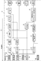
- FIG. 1A is a schematic block diagram showing a configuration of an information information system and a sensor system according to the first embodiment.
- FIG. 1B is a schematic diagram showing the configuration of an image sensor used in the same information processing system.
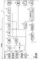
- FIG. 2 is a schematic block diagram showing the configuration of the same information processing system.
- FIG. 3 is a flowchart showing an operation example of the same information processing system.
- FIG. 4 is an explanatory diagram showing an outline of the operation of the same information processing system in the parking space detection mode.
- FIG. 5 is an explanatory diagram schematically showing an information processing result in the parking space detection mode of the same information processing system.
- FIG. 6 is an explanatory diagram showing an outline of the operation of the same information processing system in the object detection mode.
- FIG. 1A is a schematic block diagram showing a configuration of an information information system and a sensor system according to the first embodiment.
- FIG. 1B is a schematic diagram showing the configuration of an image sensor used in the same information processing system.
- FIG. 2 is
- FIG. 7 is an explanatory diagram schematically showing the information processing result in the object detection mode of the same information processing system.
- FIG. 8A is an explanatory diagram showing a situation in which the same information processing system is used.
- FIG. 8B is an explanatory diagram schematically showing how the detection result of the three-dimensional object detection process is corrected by the fusion process of the same information processing system.
- FIG. 9 is a schematic block diagram showing a configuration of an information processing system according to a third modification of the first embodiment.
- FIG. 10 is a schematic block diagram showing a configuration of an information processing system according to a fourth modification of the first embodiment.
- FIG. 11 is a schematic block diagram showing a configuration of an information processing system according to a fifth modification of the first embodiment.
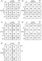
- FIG. 12A to 12E are schematic views showing the configuration of the image sensor according to the modified example of the first embodiment.
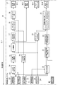
- FIG. 13 is a schematic block diagram showing the configuration of the information processing system according to the second embodiment.
- FIG. 14 is a schematic block diagram showing a configuration of an information processing system according to a modified example of the second embodiment.
- the information processing system 1 is a system used for the image sensor 3.
- the image sensor 3 has a plurality of pixels, forms an image of light from an object through an optical system on a light receiving surface on which the plurality of pixels are arranged, and photoelectrically converts the light and darkness of the light into an amount of electric charge. It is an element that outputs as an electric signal by reading this.
- the image sensor 3 is a solid-state image sensor using a semiconductor element.
- the image sensor 3 has a first pixel 31 and a second pixel 32.
- the first pixel 31 is sensitive to visible light.
- the second pixel 32 is sensitive to infrared light.
- the information processing system 1 executes various processes on the information acquired from such an image sensor 3. As a result, the information processing system 1 can obtain information processing results regarding the status of the monitoring area A1 (see FIG. 4) within the angle of view of the image sensor 3.
- the "information processing result" referred to in the present disclosure is the result of information processing obtained by the information processing system 1, and as an example, is information regarding the presence or absence of an object Ob1 (see FIG. 4) in the monitoring area A1.
- the information processing system 1 includes a first acquisition unit 11, a second acquisition unit 12, and a third acquisition unit 13.
- the first acquisition unit 11 acquires the first luminance information D1 from the first pixel 31.
- the first luminance information D1 is information regarding the pixel value of the first pixel 31.
- the second acquisition unit 12 acquires the second luminance information D2 from the second pixel 32.
- the second luminance information D2 is information regarding the pixel value of the second pixel 32.
- the third acquisition unit 13 acquires the distance information D3 from the second pixel 32.
- the distance information D3 is information related to the distance from the image sensor 3 to the object Ob1 (see FIG. 4) that reflects infrared light.
- first luminance information D1 first
- first luminance information D2 first
- first luminance information D3 first luminance information D2
- distance information D3 are different from each other, but have a correlation with each other because they are obtained from one image sensor 3.
- second luminance information D2 and the distance information D3 are both acquired from the second pixel 32, there is a strong correlation between the second luminance information D2 and the distance information D3.
- the information processing system 1 it is possible to obtain various information regarding the status of the monitoring area A1 within the angle of view of the image sensor 3 with relatively high accuracy from these three types of information. As a result, it is possible to improve the accuracy of information processing in the information processing system 1.
- the information processing system 1 and the sensor system 10 are mounted on a moving body such as an automobile.
- the moving body is a car driven by a person.
- the information processing system 1 and the sensor system 10 are used, for example, in an advanced driver assistance system (ADAS) for a moving body, an automatic driving technology, a driver monitoring technology, and the like.
- ADAS advanced driver assistance system
- the advanced driver assistance system or the automatic driving technology it is possible to detect the existence of the object Ob1 around the moving body by recognizing the monitoring area A1 around the moving body in the information processing system 1. is there.
- a person including a pedestrian, a standing person, a sitting person, a person riding a bicycle, etc.
- a living thing such as a small animal
- There are other moving bodies, walls, guardrails and structures such as traffic lights.
- the information processing system 1 basically obtains information on the status of the monitoring area A1 around the moving body as the information processing result.
- the information processing result includes information on the presence / absence of an object Ob1 in the monitoring area A1 around the moving body, information on the position of the object Ob1 existing in the monitoring area A1 in the monitoring area A1, and information on the attributes of the object Ob1. Contains one or more pieces of information selected from the group consisting of.
- “Visible light” as used in the present disclosure means an electromagnetic wave having a wavelength visible to the human eye, that is, visible light.
- the lower limit of the wavelength of visible light is in the range of approximately 360 nm or more and 400 nm or less.
- the upper limit of the wavelength of visible light is in the range of approximately 760 nm or more and 830 nm or less.
- the first pixel 31 of the image sensor 3 has sensitivity for light (visible light) in such a wavelength range. In the present embodiment, as an example, it is assumed that the first pixel 31 has sensitivity in substantially the entire wavelength range of visible light.
- the "infrared light” referred to in the present disclosure means an electromagnetic wave having a wavelength longer than that of red visible light and a wavelength shorter than that of radio waves, that is, infrared light. Therefore, the lower limit of the wavelength of infrared light is in the range of about 760 nm or more and 830 nm or less.
- the upper limit of the wavelength of infrared light is in the range of approximately 2.5 ⁇ m (near infrared) or more and 4.0 ⁇ m (mid infrared) or less.
- the second pixel 32 of the image sensor 3 has sensitivity for light (infrared light) in such a wavelength range. In the present embodiment, as an example, it is assumed that the second pixel 32 has a sensitivity near the center wavelength of the output light of the light emitting unit 4 described later.
- the "image” referred to in the present disclosure includes a moving image (moving image) and a still image (still image).
- the "moving image” includes an image composed of a plurality of still images obtained by time-lapse photography or the like.
- the image is a still image.
- the information processing system 1 is connected to the control system 2 as shown in FIG. 1A.
- the control system 2 is a system that operates by receiving an output signal from the information processing system 1.
- the output signal from the information processing system 1 includes at least the information processing result obtained by the information processing system 1, that is, the information processing result.
- the control system 2 is a system that operates by receiving an output signal from the information processing system 1. Since the output signal from the information processing system 1 includes the information processing result as described above, the control system 2 can operate according to the information processing result. As an example, the control system 2 presents information to the driver of the moving body as appropriate, such as displaying information for supporting the driving of the moving body on a display device according to the information processing result from the information processing system 1. I do. Further, the control system 2 may support the operation (steering) of the moving body by controlling the steering or braking of the moving body according to the information processing result from the information processing system 1.
- the information processing system 1 constitutes a sensor system 10 together with an image sensor 3, a light emitting unit 4 and a signal processing unit 5.
- the sensor system 10 according to the present embodiment includes an information processing system 1 and an image sensor 3.
- the sensor system 10 further includes a light emitting unit 4 and a signal processing unit 5 in addition to the information processing system 1 and the image sensor 3.
- the information processing system 1, the image sensor 3, the light emitting unit 4, and the signal processing unit 5 constituting the sensor system 10 are all mounted on the moving body.
- the control system 2 connected to the sensor system 10 is also mounted on the moving body as an example.
- control system 2 is not included in the components of the sensor system 10, but the control system 2 may be included in the components of the sensor system 10.
- the light emitting unit 4 and the signal processing unit 5 are included in the components of the sensor system 10, but the sensor system 10 includes at least one of the light emitting unit 4 and the signal processing unit 5 as a component. It does not have to be included.
- the image sensor 3 and the light emitting unit 4 are connected to the information processing system 1 via the signal processing unit 5.
- the image sensor 3 and the light emitting unit 4 are both connected to the signal processing unit 5, and the signal processing unit 5 is connected to the information processing system 1.
- the signal processing unit 5 reads an electric signal from the image sensor 3 and performs various signal processing such as filtering on the read electric signal.
- the signal processing unit 5 has a function of controlling the light emitting unit 4, and causes the light emitting unit 4 to emit light at an arbitrary timing.
- the signal processing unit 5 generates the first luminance information D1, the second luminance information D2, and the distance information D3 based on the electric signal read from the image sensor 3.
- the first luminance information D1 is information regarding the pixel value of the first pixel 31, and is generated from an electric signal read from the first pixel 31.
- the second luminance information D2 is information regarding the pixel value of the second pixel 32, and is generated from the electric signal read from the second pixel 32.
- the distance information D3 is information on the distance from the image sensor 3 to the object Ob1 that reflects infrared light, and is generated from an electric signal read from the second pixel 32.
- the information processing system 1 is connected to the image sensor 3 via the signal processing unit 5, and the signal processing unit also includes the first luminance information D1, the second luminance information D2, and the distance information D3. Obtained from the image sensor 3 via 5.
- the information processing system 1 does not directly acquire the first luminance information D1 from the first pixel 31 of the image sensor 3, but indirectly through the signal processing unit 5 to obtain the first luminance information D1.
- the first luminance information D1 is acquired from the pixel 31.
- the information processing system 1 does not directly acquire the second luminance information D2 from the second pixel 32 of the image sensor 3, but indirectly from the second pixel 32 to the second via the signal processing unit 5. 2 Acquire the brightness information D2.
- the information processing system 1 does not directly acquire the distance information D3 from the second pixel 32 of the image sensor 3, but indirectly from the second pixel 32 via the signal processing unit 5. To get.
- the image sensor 3 has a plurality of pixels including a plurality of first pixels 31 and a plurality of second pixels 32 in the row direction (longitudinal direction) and the column direction (vertical direction) of the light receiving surface. It is arranged two-dimensionally so that it is lined up in both directions (horizontally).
- FIG. 1B is a schematic diagram for showing an arrangement of a plurality of first pixels 31 and a plurality of second pixels 32, and in reality, a large number of first pixels 31 and a large number of second pixels 32 are image sensors. It may be lined up on the light receiving surface of 3.
- FIG. 1B is a schematic diagram for showing an arrangement of a plurality of first pixels 31 and a plurality of second pixels 32, and in reality, a large number of first pixels 31 and a large number of second pixels 32 are image sensors. It may be lined up on the light receiving surface of 3.
- FIG. 1B is a schematic diagram for showing an arrangement of a plurality of first pixels 31 and a plurality of second pixels 32,
- 16 pixels (8 first pixels 31 and 8 second pixels 32) are arranged side by side in the row direction and the column direction of the light receiving surface, respectively.
- the first pixel 31 having sensitivity to visible light is given the letter “W” to mean “white”
- the second pixel 32 having sensitivity to infrared light is given “infrared” to mean “infrared”.
- the letters "IR" are attached.
- the first brightness information D1 acquired by the information processing system 1 from the image sensor 3 via the signal processing unit 5 is obtained from the plurality of first pixels 31. It constitutes an image (brightness image) that is a set of outputs.
- the second brightness information D2 acquired by the information processing system 1 from the image sensor 3 via the signal processing unit 5 is obtained from the plurality of second pixels 32. It constitutes an image (brightness image) that is a set of outputs.
- the distance information D3 acquired by the information processing system 1 from the image sensor 3 via the signal processing unit 5 is a set of outputs of the plurality of second pixels 32.
- An image (distance image) is constructed.
- a plurality of first pixels 31 and a plurality of second pixels 32 are arranged in the column direction of the light receiving surface of the image sensor 3, and the first pixel 31 and the second pixel 32 are arranged in the row direction of the light receiving surface. They are arranged so that they are lined up alternately. That is, the plurality of first pixels 31 form a first pixel row arranged in the row direction of the light receiving surface, and the plurality of second pixels 32 form a second pixel row arranged in the row direction of the light receiving surface. The first pixel row and the second pixel row are alternately arranged in the row direction of the light receiving surface. According to such an arrangement, the plurality of first pixels 31 and the plurality of second pixels 32 can each realize relatively high resolution in the row direction of the light receiving surface.
- the first pixel 31 has sensitivity in substantially the entire wavelength range of such visible light. Therefore, as long as the first pixel 31 is in the wavelength range of visible light, basically, no matter which color of light is input, an output corresponding to the intensity of the light is generated. That is, the first luminance information D1 output from the first pixel 31 is light / dark information representing the intensity of the light input to the first pixel 31.
- the number of first pixels 31 (number of pixels) and the number of second pixels 32 (number of pixels) in the image sensor 3 are the same.
- the number of first pixels 31 (number of pixels) and the number of second pixels 32 (number of pixels) in the image sensor 3 may be different.
- an infrared cut filter that shields infrared light is arranged on the front surface of the first pixel 31.
- the infrared cut filter is not an essential configuration and can be omitted as appropriate.
- the light emitting unit 4 is arranged together with the image sensor 3 toward the monitoring area A1.
- the light emitting unit 4 outputs light toward at least the monitoring area A1.
- the light emitting unit 4 outputs light in a wavelength range in which at least the second pixel 32 of the image sensor 3 has sensitivity, that is, infrared light.
- an element such as a light emitting diode (LED: Light Emitting Diode) or a laser diode, which has a relatively high response speed and is capable of high-speed modulation (high-speed blinking), is used.
- information (distance information D3) regarding the distance to the object Ob1 existing in the monitoring area A1 can be obtained by the ToF (Time-of-Flight) method. Be done. That is, the time from when the light emitting unit 4 emits light until the output light of the light emitting unit 4 is reflected by the object Ob1 and received by the second pixel 32 of the image sensor 3 is the distance from the image sensor 3 to the object Ob1. It changes according to. Utilizing this fact, it is possible to measure the distance to the object Ob1 that reflects the light by measuring the flight time of the light (infrared light in this case).
- the signal processing unit 5 monitors the intensity-modulated light (hereinafter, also referred to as “intensity-modulated light”) from the light emitting unit 4. Output to A1. Then, the signal processing unit 5 measures the time using the phase difference between the phase of the intensity change at the time of light reception by the image sensor 3 and the phase of the intensity change at the time of projecting from the light emitting unit 4. If the frequency of the intensity change in the intensity-modulated light is constant, the phase difference is converted into the distance to the object Ob1 by a relatively simple calculation.
- the intensity-modulated light whose intensity changes is projected from the light emitting unit 4 to the monitoring area A1 and the intensity of the light received by one second pixel 32 of the image sensor 3 changes. Since the time difference of the same phase reflects the distance to the object Ob1, if the speed of light is c [m / s] and the time difference ⁇ t [s] is used, the distance L to the object Ob1 is expressed by the following equation 1. To.
- the light receiving intensity may be obtained for each of the second pixels 32 of the image sensor 3 for a plurality of different phases of the modulated signal.
- the amount of received light in each phase section having a predetermined phase width (time width) is detected, and the received output corresponding to this amount of received light is calculated for the phase difference ⁇ .
- the phase intervals are 90 degree intervals, four phase intervals having the same phase interval for one period of the modulated signal can be obtained periodically.
- the amount of received light for each phase section is C0 to C3
- the phase difference ⁇ is expressed by the following equation 3.
- phase difference ⁇ tan -1 ⁇ (C0-C2) / (C1-C3) ⁇ (Equation 3)
- the sign of the phase difference ⁇ changes depending on which phase of the modulated signal the received light amounts C0 to C3 correspond to, but the phase difference ⁇ may use an absolute value.
- the signal processing unit 5 drives the light emitting unit 4 by giving a modulated signal to the light emitting unit 4 so that the intensity-modulated light as described above is projected.
- a light receiving output corresponding to the received light amounts C0 to C3 for each of the four phase sections is obtained from the image sensor 3, and the light receiving output (electric signal) of the image sensor 3 is input to the signal processing unit 5.
- the signal processing unit 5 performs an operation to obtain the distance to the object Ob1 using the light receiving output. At this time, the signal processing unit 5 gives the image sensor 3 a read signal generated based on the reference signal synchronized with the modulated signal, and reads the received light output.
- the information processing system 1 has various functions in addition to the first acquisition unit 11, the second acquisition unit 12, and the third acquisition unit 13. That is, as shown in FIG. 2, the information processing system 1 further includes a noise processing unit 14, a coordinate conversion unit 15, a separation unit 16, a three-dimensional object detection unit 17, a fusion unit 18, and a tracking unit 19. Further, the information processing system 1 includes a two-dimensional object detection unit 20, a first synthesis unit 21, a second synthesis unit 22, a white line candidate area detection unit 23, a white line candidate area bird's-eye view conversion unit 24, a free space detection unit 25, and a parking frame. It further includes a detection unit 26 and an output unit 27.
- the information processing system 1 mainly includes a computer system (including a server and cloud computing) having one or more processors and one or more memories.
- the processor realizes the function of the information processing system 1 by executing the program recorded in the memory.
- the program may be pre-recorded in memory, provided by being recorded on a non-temporary recording medium such as a memory card, or provided through a telecommunication line.
- the above program is a program for making one or more processors function as the information processing system 1.
- odometry information D4 (denoted as “Odometry” in the figure) and confidence information D5 (denoted as “Conf” in the figure) are further input to the information processing system 1. That is, a total of five types of data (information) of the first brightness information D1, the second brightness information D2, the distance information D3, the odometry information D4, and the confidence information D5 are input to the information processing system 1.
- the odometry information D4 includes, for example, the tilt angle of the moving body, the traveling direction of the moving body, the moving speed of the moving body, the acceleration applied to the moving body, the accelerator pedal depression amount (accelerator opening), the brake pedal depression amount or the steering angle.
- Etc. which includes information that can be detected by a sensor mounted on a moving body.
- the odometry information D4 is information based on the current position of the moving body that can be detected using GPS (Global Positioning System) or the like, and is, for example, the number of lanes on the road at the current position, the distinction between white and yellow lines, and the roadway. Includes width, presence or absence of sidewalks, slope or curve curvature, etc.
- Confidence information D5 is information related to the reliability of data. As an example, the confidence information D5 is used to determine whether or not the distance information D3 corresponds to pseudo-distance information affected by interference, multipath, or the like. Similarly, the confidence information D5 is used to determine whether or not the first luminance information D1 or the second luminance information D2 corresponds to pseudo-luminance information.
- the first acquisition unit 11 is connected to the signal processing unit 5. That is, the first acquisition unit 11 is connected to the first pixel 31 of the image sensor 3 via the signal processing unit 5. As described above, the first acquisition unit 11 acquires the first luminance information D1 regarding the pixel value of the first pixel 31 from the first pixel 31. In the present embodiment, the first acquisition unit 11 indirectly acquires the first luminance information D1 from the first pixel 31 via the signal processing unit 5.
- the second acquisition unit 12 is connected to the signal processing unit 5. That is, the second acquisition unit 12 is connected to the second pixel 32 of the image sensor 3 via the signal processing unit 5. As described above, the second acquisition unit 12 acquires the second luminance information D2 regarding the pixel value of the second pixel 32 from the second pixel 32. In the present embodiment, the second acquisition unit 12 indirectly acquires the second luminance information D2 from the second pixel 32 via the signal processing unit 5.
- the third acquisition unit 13 is connected to the signal processing unit 5. That is, the third acquisition unit 13 is connected to the second pixel 32 of the image sensor 3 via the signal processing unit 5. As described above, the third acquisition unit 13 acquires the distance information D3 regarding the distance from the image sensor 3 to the object Ob1 that reflects infrared light from the second pixel 32. In the present embodiment, the third acquisition unit 13 indirectly acquires the distance information D3 from the second pixel 32 via the signal processing unit 5.
- the noise processing unit 14 corrects the distance information D3 by using the distance information D3 and one or more information selected from the group consisting of the first luminance information D1 and the second luminance information D2.
- One or more information selected from the group consisting of the first luminance information D1 and the second luminance information D2 includes the first luminance information D1, the second luminance information D2, the first luminance information D1 and the second luminance information D2. It is one of the combined luminance information (hereinafter, also referred to as “composite image”).
- the noise processing unit 14 is connected to the third acquisition unit 13. In the present embodiment, the noise processing unit 14 is connected to the second acquisition unit 12 via the first synthesis unit 21.
- the first luminance information D1 or the second luminance information D2 is not directly input to the noise processing unit 14, but is indirectly input via the first combining unit 21. Since the distance information D3 alone has a relatively low SN ratio and a large noise ratio, the noise processing unit 14 reduces the noise of the distance information D3. The operation of the noise processing unit 14 will be described in detail in the column of "(3) Operation".
- the coordinate conversion unit 15 is provided after the noise processing unit 14.
- the coordinate conversion unit 15 performs coordinate conversion processing on the (noise-reduced) distance information D3 in the Cartesian coordinate system of X, Y, and Z. Specifically, the coordinate conversion unit 15 generates a point cloud (point cloud data) having coordinate values of X, Y, and Z based on the distance information D3.
- the separation unit 16 separates the object Ob1 and the peripheral region located around the object Ob1.
- the "peripheral area" referred to in the present disclosure is, for example, a road surface, a ground surface, a floor surface, or the like that is excluded from the detection target when detecting the presence or absence of the object Ob1.
- the separation unit 16 separates a region other than the road surface or the like including the object Ob1 from a peripheral region such as the road surface.
- the separation unit 16 separates the object Ob1 and the peripheral region of the distance information D3 (point cloud) after the coordinate conversion input from the coordinate conversion unit 15.
- the separation unit 16 first extracts a component corresponding to the peripheral region from the distance information D3 after the coordinate conversion input from the coordinate conversion unit 15.
- the separation unit 16 removes the extracted peripheral region from the distance information D3 after the coordinate conversion, and outputs the component corresponding to the object Ob1 in the distance information D3 to the three-dimensional object detection unit 17 in the subsequent stage. ..
- the peripheral region is all regions other than the object Ob1 in the distance information D3, and includes not only the region near the object Ob1 but also the region far away from the object Ob1.
- the separation unit 16 outputs the information regarding the separated peripheral region to the output unit 27 as the road surface information D12.
- odometry information D4 is also input to the separation unit 16. The operation of the separation unit 16 will be described in detail in the column of "(3) Operation".
- the three-dimensional object detection unit 17 detects the object Ob1 based on the distance information D3.
- the distance information D3 in the state where the peripheral region is removed is input to the three-dimensional object detection unit 17 from the separation unit 16.
- the three-dimensional object detection unit 17 detects the object Ob1 in the monitoring area A1 by using the distance information D3 input from the separation unit 16, and when it is determined that the object Ob1 exists, the distance information D3 corresponding to the object Ob1. (Point cloud) is output as a "target".
- the three-dimensional object detection unit 17 detects the object Ob1 based on one or more information selected from the group consisting of the first luminance information D1 and the second luminance information D2 in addition to the distance information D3. I do. That is, there is a noise processing unit 14 in front of the three-dimensional object detection unit 17, and the noise processing unit 14 selects one or more from the group consisting of the first luminance information D1 and the second luminance information D2 as described above.
- the distance information D3 is corrected by indirectly using the information of. Therefore, the three-dimensional object detection unit 17 indirectly uses not only the distance information D3 but also one or more information selected from the group consisting of the first luminance information D1 and the second luminance information D2 to indirectly use the object Ob1. It will be detected.
- the three-dimensional object detection unit 17 may detect the object Ob1 based on the first luminance information D1 corrected according to the timing of the second luminance information D2 in addition to the distance information D3. In this case, the three-dimensional object detection unit 17 does not directly use the second luminance information D2, but uses the first luminance information D1 corrected to match the timing of the second luminance information D2, and uses the object Ob1. Will be detected. The operation of the three-dimensional object detection unit 17 will be described in detail in the column of "(3) Operation".
- the fusion unit 18 synthesizes the detection result of the two-dimensional object detection unit 20 and the detection result of the three-dimensional object detection unit 17.
- the three-dimensional object detection unit 17 and the two-dimensional object detection unit 20 are arranged in front of the fusion unit 18, and the fusion unit 18 contains the detection result of the three-dimensional object detection unit 17 and the two-dimensional object detection unit 17.
- the detection result of the object detection unit 20 is input.
- the detection result of the three-dimensional object detection unit 17 corresponds to at least the detection result of the object Ob1 based on the distance information D3, that is, the three-dimensional detection result of the object Ob1.
- the detection result of the two-dimensional object detection unit 20 is the detection result of the object Ob1 based on one or more information selected from the group consisting of the first luminance information D1 and the second luminance information D2, that is, the two-dimensional detection result of the object Ob1.
- the fusion unit 18 does not directly synthesize one or more information selected from the group consisting of the first luminance information D1 and the second luminance information D2 and the distance information D3, but rather the first luminance information D1 and
- the detection result of the object Ob1 based on each of one or more information selected from the group consisting of the second luminance information D2 and the distance information D3 is synthesized.
- the fusion unit 18 indirectly synthesizes one or more information selected from the group consisting of the first luminance information D1 and the second luminance information D2 and the distance information D3.
- the object Ob1 is detected in the front stage of the fusion unit 18, and the fusion unit 18 includes the first luminance information D1 and the second luminance information D2 based on the detection result of the object Ob1.
- the distance information D3 is combined with one or more pieces of information selected from the group.
- the "detection result of the object Ob1" here means the detection results of both the three-dimensional object detection unit 17 and the two-dimensional object detection unit 20. More specifically, the fusion unit 18 uses the detection result of the object Ob1 based on one or more information selected from the group consisting of the first luminance information D1 and the second luminance information D2, and uses the detection result of the object Ob1 based on the distance information D3. Change the detection result of.
- the fusion unit 18 corrects the detection result (three-dimensional detection result) of the three-dimensional object detection unit 17 by using the detection result (two-dimensional detection result) of the two-dimensional object detection unit 20. As a result, the fusion unit 18 synthesizes the two-dimensional detection result and the three-dimensional detection result.
- the fusion unit 18 corrects the detection result of the three-dimensional object detection unit 17 by synthesizing one or more information selected from the group consisting of the first luminance information D1 and the second luminance information D2 and the distance information D3.
- the corrected detection result of the three-dimensional object detection unit 17 is output to the tracking unit 19.
- the operation of the fusion unit 18 will be described in detail in the column of "(3) Operation".
- the fusion unit 18 outputs the feedback signal Si1 to the sensor system 10 including the image sensor 3.
- the image sensor 3 outputs an electric signal in which one or more parameters selected from the group consisting of the exposure time and the frame rate are changed by the feedback signal Si1. That is, the feedback signal Si1 output by the fusion unit 18 is fed back to the sensor system 10 as shown in FIGS. 1A and 2.
- the feedback signal Si1 includes the detection result of the corrected three-dimensional object detection unit 17, which is the output of the fusion unit 18.
- the image sensor 3 outputs an electric signal in which the exposure time and / or the frame rate is changed according to the feedback signal Si1.
- the tracking unit 19 tracks the object Ob1 existing in the monitoring area A1.
- the tracking unit 19 tracks the object Ob1 by comparing the detection result (target) of the corrected three-dimensional object detection unit 17 input from the fusion unit 18 among a plurality of frames of the output of the image sensor 3, for example. I do.
- the tracking unit 19 can recognize the object Ob1 before the movement and the object Ob1 after the movement as the same object even when the object Ob1 moves in the monitoring area A1.
- the tracking result of the tracking unit 19 is output to the output unit 27 as the target information D11.
- odometry information D4 is also input to the tracking unit 19.
- the two-dimensional object detection unit 20 detects the object Ob1 based on one or more information selected from the group consisting of the first luminance information D1 and the second luminance information D2.
- the two-dimensional object detection unit 20 is connected to the first acquisition unit 11 via the first synthesis unit 21.
- the second acquisition unit 12 is also connected to the first synthesis unit 21
- the two-dimensional object detection unit 20 is also connected to the second acquisition unit 12 via the first synthesis unit 21.
- the first luminance information D1 or the second luminance information D2 is not directly input to the two-dimensional object detection unit 20, but is indirectly input via the first synthesis unit 21.
- the two-dimensional object detection unit 20 Since the output of the first synthesis unit 21 reflects one or more information selected from the group consisting of the first luminance information D1 and the second luminance information D2, the two-dimensional object detection unit 20 has the first luminance information.
- the object Ob1 is detected by indirectly using the D1 or the second luminance information D2.
- the two-dimensional object detection unit 20 uses one or more information selected from the group consisting of the first luminance information D1 and the second luminance information D2 input from the first synthesis unit 21, and the object Ob1 in the monitoring area A1. Is detected and it is determined that the object Ob1 exists, one or more information selected from the group consisting of the first luminance information D1 and the second luminance information D2 with the marker M1 (see FIG. 7) corresponding to the object Ob1. Is output.
- the two-dimensional object detection unit 20 detects the object Ob1 based on one or more information selected from the group consisting of the first luminance information D1 and the second luminance information D2. That is, the first synthesis unit 21 is in front of the two-dimensional object detection unit 20, and the first synthesis unit 21 synthesizes the first luminance information D1 and the second luminance information D2. Therefore, the two-dimensional object detection unit 20 indirectly uses a composite image in which not only the first luminance information D1 or the second luminance information D2 but also the first luminance information D1 and the second luminance information D2 are combined to form the object Ob1. Can be detected.
- the operation of the two-dimensional object detection unit 20 will be described in detail in the column of "(3) Operation".
- the first synthesis unit 21 is connected to the first acquisition unit 11 and the second acquisition unit 12.
- the first combining unit 21 synthesizes the first luminance information D1 and the second luminance information D2.
- a composite image is generated by synthesizing the first luminance information D1 and the second luminance information D2.
- the "composite" referred to in the present disclosure includes weighted compositing. For example, if the weighting coefficients of the first luminance information D1 and the second luminance information D2 are "1: 0", the composite image is the first compositing unit.
- the first luminance information D1 is output as it is from 21.
- the first synthesizer 21 includes a function as a selector that selectively outputs the first luminance information D1 and the second luminance information D2.
- the first luminance information D1 and the second luminance information D2 synthesized by the first combining unit 21 are input to the noise processing unit 14 and the two-dimensional object detecting unit 20.
- the first synthesis unit 21 is appropriately controlled so that the output of the first synthesis unit 21 becomes a composite image suitable for the operation of the noise processing unit 14 and the two-dimensional object detection unit 20. Further, the composite image input from the first composite unit 21 is composited by appropriately changing the weighting coefficient according to the situation of the monitoring area A1 such as daytime / nighttime or weather (rain, fog). Is preferable.
- the second synthesis unit 22 is connected to the first acquisition unit 11 and the second acquisition unit 12.
- the second combining unit 22 synthesizes the first luminance information D1 and the second luminance information D2. Similar to the first synthesis unit 21, the second synthesis unit 22 also includes a function as a selector that selectively outputs the first luminance information D1 and the second luminance information D2.
- the first luminance information D1 and the second luminance information D2 synthesized by the second combining unit 22 are input to the white line candidate region detecting unit 23. Therefore, it is preferable that the second synthesis unit 22 is appropriately controlled so that the output of the second synthesis unit 22 becomes a composite image suitable for the operation of the white line candidate region detection unit 23. Further, the composite image input from the second composite unit 22 is composited by appropriately changing the weighting coefficient according to the situation of the monitoring region A1 such as daytime / nighttime or weather (rain, fog). Is preferable.
- the output of the first synthesis unit 21 is input to the two-dimensional object detection unit 20, and the output of the second synthesis unit 22 is input to the white line candidate region detection unit 23.
- the weight coefficients at the time of synthesis are different between the first synthesis unit 21 and the second synthesis unit 22. ..
- the first synthesis unit 21 and the second synthesis unit 22 both function as a "synthesis unit” that synthesizes the first luminance information D1 and the second luminance information D2.
- the compositing unit (first compositing unit 21 and second compositing unit 22) synthesizes the first luminance information D1 and the second luminance information D2 so as to correct the information regarding the positions of the first pixel 31 and the second pixel 32.
- the synthesizing unit changes the weighting coefficient for synthesizing the first luminance information D1 and the second luminance information D2 according to the input reference information D6. That is, the reference information D6 is information on the situation of the monitoring area A1 such as daytime / nighttime or weather (rain, fog), and includes, for example, information on the illuminance and / or humidity around the object Ob1. There is.
- the white line candidate area detection unit 23 detects a candidate area of the white line 62 (see FIG. 4) drawn on the road surface 61 (see FIG. 4).
- the white line candidate region detection unit 23 detects the candidate region of the white line 62 based on the composite image of the first luminance information D1 and the second luminance information D2 input from the second composite unit 22. Confidence information D5 is also input to the white line candidate region detection unit 23.
- the detection of the white line 62 is, as an example, a portion where the pixel value (brightness) suddenly changes by performing edge extraction or the like using a filter on the composite image of the first luminance information D1 and the second luminance information D2. It is realized by detecting.
- the white line 62 to be detected by the white line candidate region detection unit 23 is not limited to the white line, and may be, for example, a yellow line (yellow line), a picture, a pattern, or the like.
- the white line candidate area bird's-eye view conversion unit 24 is provided after the white line candidate area detection unit 23.
- the bird's-eye view conversion unit 24 of the white line candidate area viewed at least the candidate area of the white line 62 detected by the white line candidate area detection unit 23 and its periphery from directly above the composite image of the first luminance information D1 and the second luminance information D2. Coordinate conversion is performed so that the image becomes a bird's-eye view.
- the free space detection unit 25 detects the free space in the monitoring area A1 based on the distance information D3, that is, the vacant space.
- the distance information D3 separated into the object Ob1 and the peripheral region located around the object Ob1 is input to the free space detection unit 25 from the separation unit 16.
- the free space detection unit 25 detects the free space in the monitoring area A1 by using the distance information D3 input from the separation unit 16.
- the detection result of the free space detection unit 25 is output to the output unit 27 as free space information D13 (denoted as "free space” in the figure).
- odometry information D4 is also input to the free space detection unit 25.
- the parking frame detection unit 26 detects an empty parking frame in the monitoring area A1, that is, an empty parking frame in which another vehicle is not parked.
- an empty parking frame in the monitoring area A1 that is, an empty parking frame in which another vehicle is not parked.
- multiple parking lots are provided, and parking lot users search for vacant parking lots and park vacantly. Park your vehicle (moving object) in the frame.
- the parking frame detection unit 26 in such a case, it is possible to automatically search for an empty parking frame.
- the detection result of the free space detection unit 25 and the output of the bird's-eye view conversion unit 24 of the white line candidate area (candidate area of the white line 62 after coordinate conversion) are input to the parking frame detection unit 26.
- the parking frame detection unit 26 performs pairing with the detection result of the free space detection unit 25 and the output of the bird's-eye view conversion unit 24 of the white line candidate area (candidate area of the white line 62 after coordinate conversion), and determines an empty parking frame. .. For example, the parking frame detection unit 26 determines that a parking frame having a size that allows a moving body to be parked in the monitoring area A1 and that partially overlaps with the fleece case is regarded as an empty parking frame. The detection result of the parking frame detection unit 26 is output to the output unit 27 as vacant parking frame information D14 (denoted as “vacant parking frame” in the figure).
- the output unit 27 outputs the information processing result regarding the status of the monitoring area A1 within the angle of view of the image sensor 3, which is performed based on the first luminance information D1, the second luminance information D2, and the distance information D3. That is, the information processing system 1 according to the present embodiment executes various information processing regarding the status of the monitoring area A1 based on the first luminance information D1, the second luminance information D2, and the distance information D3 acquired from the image sensor 3. Then, the result is output by the output unit 27.
- the output unit 27 obtains target information D11, road surface information D12, free space information D13 and, respectively, from the tracking unit 19, the separation unit 16, the free space detection unit 25, and the parking frame detection unit 26.
- the empty parking frame information D14 is output.
- the output unit 27 outputs this information to the control system 2.
- the information processing results include information on the presence or absence of the object Ob1 in the monitoring area A1 around the moving body, information on the position of the object Ob1 existing in the monitoring area A1 in the monitoring area A1, and the object Ob1. Contains information about the attribute and at least one of them.
- the target information D11 includes information on the presence / absence of the object Ob1 in the monitoring area A1 around the moving body, information on the position of the object Ob1 existing in the monitoring area A1 in the monitoring area A1, and the object Ob1. Includes all information about the attributes of.
- the “attribute” referred to in the present disclosure includes, for example, the type of the object Ob1, that is, whether it is a person or not, whether it is a moving body (person, automobile, bicycle, etc.) or a fixed object, or a roadside tree, a traffic light, a guardrail, etc. .. Further, the “attribute” of the object Ob1 also includes the size, color or movement (change) of the object Ob1. Further, if the object Ob1 is a person, its gender, height, body shape, age group, etc., and if the object Ob1 is a moving body, its moving direction or moving speed, etc. are also included in the "attribute" of the object Ob1.
- the information output by the output unit 27 changes as appropriate according to the request of the output destination.
- the output unit 27 may output meta-meta-information. ..
- the information system 1 has a plurality of operation modes including at least a parking space detection mode and an object detection mode. Each of these plurality of operation modes can be individually enabled / disabled. For example, if the parking space detection mode is enabled and all other operation modes are disabled, the information processing system 1 has the parking space. Works only in detection mode.
- the parking space detection mode is an operation mode for detecting an empty parking frame, and in this operation mode, the above-mentioned empty parking frame information D14 is output from the output unit 27.
- the object detection mode is an operation mode for detecting the object Ob1 in the monitoring area A1, and in this operation mode, the target information D11 described above is output from the output unit 27.
- FIG. 3 is a flowchart showing an operation example of the information processing system 1 according to the present embodiment.
- the information processing system 1 has a first acquisition process (S1) for acquiring the first luminance information D1, a second acquisition process (S2) for acquiring the second luminance information D2, and distance information.
- the third acquisition process (S3) for acquiring D3 is executed.
- the information processing system 1 executes the first acquisition process, the second acquisition process, and the third acquisition process (S1 to S3) at any time in the first acquisition unit 11, the second acquisition unit 12, and the third acquisition unit 13. .
- the noise processing unit 14 uses the distance information D3 and one or more information selected from the group consisting of the first luminance information D1 and the second luminance information D2 to provide the distance information.
- D3 By correcting D3, noise removal processing for reducing the noise of the distance information D3 is executed (S4).
- the noise removal processing will be described in detail in the column of "(3.2) Noise removal processing".
- the information processing system 1 executes a separation process in the separation unit 16 to separate the object Ob1 and the peripheral region located around the object Ob1 with respect to the distance information D3 after the coordinate conversion (S5). ..
- the separation process will be described in detail in the column of "(3.3) Separation process".
- the information processing system 1 determines whether or not the object detection mode is valid (S6). If the object detection mode is enabled (S6: Yes), the information processing system 1 executes a series of processes (S7 to S11) for detecting the object Ob1. That is, the information processing system 1 executes a three-dimensional object detection process in which the three-dimensional object detection unit 17 detects the object Ob1 (S7), and the two-dimensional object detection unit 20 detects the object Ob1.
- the object detection process is executed (S8).
- the three-dimensional object detection process will be explained in detail in the column of "(3.4) Three-dimensional object detection process", and the two-dimensional object detection process will be explained in detail in the column of "(3.5) Two-dimensional object detection process". To do.
- the information processing system 1 determines the presence or absence of the object Ob1 from the result of the fusion process (S10). If the object Ob1 exists (S10: Yes), the information processing system 1 outputs the target information D11 by the output unit 27 (S11), and determines whether or not the parking space detection mode is valid (S12). If the object Ob1 does not exist (S10: Yes), the information processing system 1 shifts to the process S12 without outputting the target information D11.
- the information processing system 1 executes a series of processes (S13 to S16) for detecting an empty parking frame. That is, the information processing system 1 detects the white line 62 (candidate area) by the white line candidate area detection unit 23 (S13), and detects the free space by the free space detection unit 25 (S14). From these results, the information processing system 1 determines whether or not there is an empty parking frame in the monitoring area A1 by the parking frame detection unit 26 (S15).
- the information processing system 1 If there is an empty parking frame (S15: Yes), the information processing system 1 outputs the empty parking frame information D14 to the output unit 27 (S16), and ends the series of processing. If there is no vacant parking frame (S15: Yes), the information processing system 1 ends a series of processes without outputting the vacant parking frame information D14.
- the information processing system 1 skips a series of processes (S7 to S11) for detecting the object Ob1 and shifts to the process S12. If the parking space detection mode is invalid (S12: No), the information processing system 1 skips a series of processes (S13 to S16) for detecting an empty parking frame and ends the process.
- the information information system 1 repeatedly executes a series of processes S1 to S16 as described above.
- the flowchart of FIG. 3 is merely an example of the overall operation of the information processing system 1, and the processing may be omitted or added as appropriate, or the order of the processing may be changed as appropriate.
- the order of the processes S1 to S3 may be changed, and after the second luminance information D2 and the distance information D3 are acquired (S2, S3), the first luminance information D1 may be acquired (S1).
- FIG. 4 and 5 are explanatory views showing an outline of the operation of the information processing system 1 in the parking space detection mode.
- FIG. 4 shows a state in which the monitoring area A1 is photographed by the image sensor 3, and the first luminance information D1, the second luminance information D2, and the distance information D3 obtained from the output of the image sensor 3 are input to the information processing system 1. It is represented schematically.
- FIG. 5 schematically shows the information processing result in the information processing system 1 in the parking space detection mode, that is, the empty parking frame information D14.
- the plurality of parking frames include a parking frame in which another vehicle (object Ob1) is parked and a parking frame (empty parking frame) in which another vehicle (object Ob1) is not parked.
- the information processing system 1 acquires the first luminance information D1, the second luminance information D2, and the distance information D3 from the image sensor 3 (via the signal processing unit 5) as shown in FIG. ..
- the first luminance information D1 is light / dark information representing the intensity of light input to the plurality of first pixels 31, the image is apparently a relatively faithful reproduction of the monitoring region A1 in the real space.
- the second luminance information D2 is light / dark information indicating the intensity of infrared light output from the light emitting unit 4 and input to the plurality of second pixels 32, the object Ob1 having a relatively low reflectance to infrared light is used. The image is not sufficiently reproduced and the contrast is low as compared with the first luminance information D1.
- the distance information D3 is a distance image representing the flight distance of infrared light output from the light emitting unit 4 and input to the plurality of second pixels 32, that is, the distance from the image sensor 3 to the object Ob1, the distance information D3 is relative to the infrared light.
- the object Ob1 having a relatively low reflectance is not sufficiently reproduced.
- the information processing system 1 uses the first luminance information D1, the second luminance information D2, and the distance information D3 to execute a series of processes (S13 to S16) for detecting an empty parking frame as described above. ..
- a parking frame in which another vehicle (object Ob1) is not parked is detected as an empty parking frame, and empty parking frame information D14 is generated.
- the vacant parking frame information D14 includes at least information regarding the position of the vacant parking frame within the monitoring area A1.
- the control system 2 in which the empty parking frame information D14 is input from the information processing system 1 displays an image in which the empty parking frame information D14 is superimposed on the image of the monitoring area A1 as shown in FIG. It may be displayed on a display device. In this case, it is preferable that the image displayed on the display device is provided with a balloon (denoted as "Free Space" in FIG. 5) indicating that the empty parking frame information D14 points to the empty parking frame.
- a ring clasp 63 (see FIG. 4) is installed in the parking frame surrounded by a pair of white lines 62.
- the information processing system 1 recognizes the ring fastening 63 as the object Ob1. That is, in the present embodiment, in the separation process (S5), which is a pre-process of a series of processes (S13 to S16) for detecting an empty parking frame, the distance information D3 after coordinate conversion is the object Ob1 and the periphery. The area and is separated. Therefore, if the parking frame is vacant, the area of the road surface 61 surrounded by the white line 62 and the ring clasp 63 is detected as the vacant parking frame.
- FIG. 6 and 7 are explanatory views showing an outline of the operation of the information processing system 1 in the object detection mode.
- FIG. 6 schematically shows the state of the monitoring area A1.
- FIG. 7 schematically represents the information processing result in the information processing system 1 in the object detection mode, that is, the target information D11.
- a scene in which a moving body is stopped at an intersection is assumed, and a road surface 61 including a roadway 611 and a sidewalk 612, a pedestrian crossing 64, etc., and a pedestrian crossing 64 are provided in the monitoring area A1.
- a road surface 61 including a roadway 611 and a sidewalk 612, a pedestrian crossing 64, etc., and a pedestrian crossing 64 are provided in the monitoring area A1.
- the sidewalk 612 is higher than the roadway 611.
- the information processing system 1 acquires the first luminance information D1, the second luminance information D2, and the distance information D3 from the image sensor 3 (via the signal processing unit 5).
- the information processing system 1 uses the first luminance information D1, the second luminance information D2, and the distance information D3 to execute a series of processes (S7 to S11) for detecting the object Ob1 as described above.
- the target information D11 includes at least information regarding the position of the object Ob1 within the monitoring area A1.
- the target information D11 includes a frame-shaped marker M1 surrounding the object Ob1 and an image of the object Ob1 in the marker M1.
- the control system 2 in which the target information D11 is input from the information processing system 1 displays an image in which the target information D11 is superimposed on the image in the monitoring area A1 as shown in FIG. It may be displayed in.
- the image displayed on the display device is provided with a balloon (denoted as “Human” or “Tree” in FIG. 7) indicating the attribute of the object Ob1 indicated by the target information D11.
- the separation process (S5) which is a pre-process of a series of processes (S7 to S11) for detecting the object Ob1
- the distance information D3 after the coordinate conversion is the object Ob1 and the periphery.
- the information processing system 1 according to the present embodiment can recognize the step between the sidewalk 612, which is higher than the roadway 611, as the object Ob1. Therefore, it is also possible to detect a step on the road surface 61 (a step between the roadway 611 and the sidewalk 612) and separate only the roadway 611 as the road surface.
- the noise processing unit 14 uses one or more information selected from the group consisting of the first luminance information D1 and the second luminance information D2 input from the first combining section 21 to use the distance information D3.
- the distance information D3 is corrected so as to reduce the noise of. More specifically, when the second luminance information D2 or the composite image of the first luminance information D1 and the second luminance information D2 and the distance information D3 are used, the information obtained from the output of the second pixel 32 is obtained. Since it is used, it is possible to remove noise in the distance information D3 between the second luminance information D2 and the distance information D3 without considering the time.
- the pixels to which the information is output are the first pixel 31 and the second pixel 32, respectively, so that a time lag may occur.
- the noise of the distance information D3 is removed after correcting the time difference between the first luminance information D1 and the distance information D3 based on the predetermined offset value. Therefore, by using one or more information selected from the group consisting of the first luminance information D1 and the second luminance information D2, it is possible to correct the distance information D3 so as to reduce noise.
- the noise processing unit 14 is selected from the group consisting of the first luminance information D1 and the second luminance information D2 in order to determine a filter for removing the noise of the distance information D3 having a relatively low SN ratio.
- Use filter information of one or more pieces of information is a portion where the pixel value (brightness) suddenly changes by performing edge extraction using a filter or the like on the composite image input from the first synthesis unit 21. Is detected, and a region that is a candidate for the object Ob1 is extracted.
- the noise processing unit 14 determines a filter to be applied to the distance information D3 with reference to the region extracted from such a composite image.
- the noise processing unit 14 adopts points in which the distance variation is in the range of 1.0 [m] for the area where a person is estimated to exist from the composite image, and the points outside this range are error values. Filtering is performed.
- the accuracy of the filter is likely to be improved and the noise of the distance information D3 can be efficiently removed as compared with the case where the error value range is determined only from the distance information D3 and filtering is performed.
- the separation unit 16 separates the object Ob1 and the peripheral region located around the object Ob1 with respect to the distance information D3 (point cloud) after the coordinate conversion input from the coordinate conversion unit 15. Specifically, the separation unit 16 first determines a point at a predetermined height or less as a road surface 61, which is a peripheral region, based on the absolute height of the points (position of the Z coordinate). Then, the separation unit 16 performs clustering to group a plurality of points higher than a predetermined height and within a predetermined range, and obtains a "plane" including the plurality of points in the same group and its "normal". ..
- the separation unit 16 determines that the obtained "plane" is the road surface 61. ..
- the separation unit 16 can also obtain the inclination and unevenness of the road surface 61 by the inclination of the normal line with respect to the vertical direction (Z axis) for the distance information D3 determined to be the peripheral region.
- the separation unit 16 can output information on the peripheral region as the road surface information D12, including the inclination and unevenness of the road surface 61. That is, the road surface information D12 includes information regarding the inclination and / or unevenness of the road surface 61 included in the peripheral region.
- the three-dimensional object detection unit 17 detects the object Ob1 based on the distance information D3 input from the separation unit 16. In the present embodiment, the three-dimensional object detection unit 17 determines whether or not the distance information D3 (point cloud) in the state where the peripheral region is removed is the object Ob1. Specifically, the three-dimensional object detection unit 17 determines whether or not the object is Ob1 based on, for example, the density of points in the point cloud. That is, if the density of points in the point cloud is equal to or higher than the threshold value, the three-dimensional object detection unit 17 determines that the object Ob1 exists at a position corresponding to these points. On the other hand, if the density of points in the point cloud is less than the threshold value, the three-dimensional object detection unit 17 determines that the object Ob1 does not exist at the position corresponding to these points.
- the three-dimensional object detection unit 17 performs clustering for grouping a plurality of points within a predetermined range, and is based on the size (that is, area) of a "plane" including the plurality of points in the same group. Therefore, it may be determined whether or not the object is Ob1. In this case, if the area is equal to or larger than the threshold value, the three-dimensional object detection unit 17 determines that the object Ob1 exists at a position corresponding to these points. On the other hand, if the area is less than the threshold value, the three-dimensional object detection unit 17 determines that the object Ob1 does not exist at the position corresponding to these points.
- the noise removal processing in the previous stage of the three-dimensional object detection processing one or more information selected from the group consisting of the first luminance information D1 and the second luminance information D2 is used.
- the distance information D3 is corrected. Therefore, in the three-dimensional object detection process, not only the distance information D3 but also one or more information selected from the group consisting of the first luminance information D1 and the second luminance information D2 is indirectly used to detect the object Ob1. Will be done.
- the information regarding the position of the object Ob1 in the monitoring area A1 and the information regarding the attributes of the object Ob1 are also determined. That is, when the object Ob1 exists, its position and attributes are also determined by the three-dimensional object detection process.
- the attribute of the object Ob1 determined by the three-dimensional object detection process is only the size of the object Ob1.
- the two-dimensional object detection unit 20 is based on one or more information selected from the group consisting of the first luminance information D1 and the second luminance information D2 input from the first synthesis unit 21. Detects the object Ob1. Basically, the two-dimensional object detection unit 20 moves the templates of various objects Ob1 on the luminance image, and based on the similarity with the template of the partial image to be compared with the template, whether or not the object Ob1 is present. Make a decision. That is, if the degree of coincidence between the partial image and the template is equal to or greater than the threshold value, the two-dimensional object detection unit 20 determines that the object Ob1 exists at a position corresponding to the partial image. On the other hand, if the degree of coincidence between the partial image and the template is less than the threshold value, the two-dimensional object detection unit 20 determines that the object Ob1 does not exist at the position corresponding to the partial image.
- the two-dimensional object detection unit 20 uses, for example, a HOG (Histograms of Oriented Gradients) feature amount, a convolutional neural network (CNN), or the like from the first luminance information D1 and the second luminance information D2.
- the object Ob1 may be detected based on one or more pieces of information selected from the group.
- the information regarding the position of the object Ob1 in the monitoring area A1 and the information regarding the attributes of the object Ob1 are also determined. That is, when the object Ob1 exists, its position and attributes are also determined by the two-dimensional object detection process.
- the attributes of the object Ob1 determined by the two-dimensional object detection process include the size and type of the object Ob1.
- the object Ob1 is detected by a means different from the three-dimensional object detection process.
- the fusion unit 18 synthesizes the detection result of the two-dimensional object detection unit 20 and the detection result of the three-dimensional object detection unit 17. That is, the detection result of the three-dimensional object detection process is at least the detection result of the object Ob1 performed based on the distance information D3, and the detection result of the two-dimensional object detection process is at least the first luminance information D1 or the second luminance. It is a detection result of the object Ob1 performed based on the information D2.
- the three-dimensional object detection process detects the object Ob1 based on the distance information D3 generated when the infrared light output from the light emitting unit 4 is reflected by the object Ob1 and input to the second pixel 32. There is a possibility that the object Ob1 having a relatively low reflectance to external light cannot be detected. On the other hand, since the two-dimensional object detection process does not use the distance information D3, it is not possible to detect the three-dimensional object Ob1 that reflects the distance from the image sensor 3 to the object Ob1. In the fusion process, by synthesizing the detection results of both the three-dimensional object detection process and the two-dimensional object detection process, it is possible to obtain the detection result of the object Ob1 that compensates for each defect. That is, even if the object Ob1 has a relatively low reflectance to infrared light, it is possible to detect the three-dimensional object Ob1 that reflects the distance from the image sensor 3 to the object Ob1.
- the fusion unit 18 uses the detection result of the two-dimensional object detection process (the detection result of the object Ob1 based on the first luminance information D1 or the second luminance information D2), and the detection result of the three-dimensional object detection process. (Detection result of object Ob1 based on distance information D3) is corrected. For example, for an object Ob1 including a portion having a low reflectance to infrared light, a point corresponding to a part of the object Ob1 may be lost in the detection result (point cloud) of the three-dimensional object detection process. .. Therefore, in the fusion process, the detection result of the three-dimensional object detection process is corrected (complemented) by the detection result of the two-dimensional object detection process so as to complement the missing points.
- FIGS. 8A and 8B are explanatory views schematically showing how the detection result of the three-dimensional object detection process is corrected (complemented) by the fusion process.
- a road surface 61 and a person (object Ob1) exist in the monitoring area A1.
- the reflectance of the jacket worn by a person (object Ob1) to infrared light is relatively low.
- the upper body (torso) of the person (object Ob1) is found in the detection result (point cloud) of the three-dimensional object detection process.
- Corresponding point may be missing.
- the upper body (torso) of the missing person (object Ob1) is represented by an imaginary line (dashed line).
- the data as shown in FIG. 8B can be obtained by superimposing the frame-shaped marker M1 surrounding the object Ob1 in the detection result of the two-dimensional object detection process on the detection result of the three-dimensional object detection process. Then, in the fusion process, the detection result of the three-dimensional object detection process is corrected (complemented) according to the following flow.
- the fusion unit 18 first obtains a representative value (mean value, median value, mode value, etc.) of the distance from a plurality of points existing in the region surrounded by the marker M1 to the object Ob1. Further, the fusion unit 18 adjusts the position of the marker M1 so that the representative value of the obtained distance and the position of the lower end of the marker M1 match. For example, when the representative value of the obtained distance is 5.0 [m], the position of the lower end of the marker M1 on the road surface 61 (corresponding to the feet of a person) is set to the position of 5.0 [m]. The fusion unit 18 adjusts the position of the marker M1.
- a representative value mean value, median value, mode value, etc.
- the fusion unit 18 determines that the point existing in the region surrounded by the marker M1 in the detection result (point cloud) of the three-dimensional object detection process is the target information D11 corresponding to the object Ob1. .. At this time, the fusion portion 18 may complement the missing point, that is, the point corresponding to the upper body (torso) of the person (object Ob1).
- the detection result of the three-dimensional object detection process (distance information D3 corresponding to the object Ob1) by using the detection result of the two-dimensional object detection process.
- the detection result (target information D11) of the object Ob1 with improved accuracy as compared with the three-dimensional object detection process can be obtained.
- the attribute of the object Ob1 includes not only the size of the object Ob1 but also the type.
- the first embodiment is only one of the various embodiments of the present disclosure.
- the first embodiment can be changed in various ways depending on the design and the like as long as the object of the present disclosure can be achieved.
- Each figure described in the present disclosure is a schematic view, and the ratio of the size and the thickness of each component in each figure does not necessarily reflect the actual dimensional ratio.
- the same function as the information processing system 1 according to the first embodiment may be realized by an information processing method, a program, a non-temporary recording medium on which the program is recorded, or the like.
- the information processing method according to one aspect is a method of processing information input from the image sensor 3, and is a first acquisition process (corresponding to “S1” in FIG. 3) and a second acquisition process (“S1” in FIG. 3).
- the image sensor 3 has a first pixel 31 having sensitivity to visible light and a second pixel 32 having sensitivity to infrared light.
- the first acquisition process is a process of acquiring the first luminance information D1 relating to the pixel value of the first pixel 31 from the first pixel 31.
- the second acquisition process is a process of acquiring the second luminance information D2 relating to the pixel value of the second pixel 32 from the second pixel 32.
- the third acquisition process is a process of acquiring the distance information D3 regarding the distance from the image sensor 3 to the object Ob1 that reflects infrared light from the second pixel 32.
- the program according to one aspect is a program for causing one or more processors to execute the above information processing method.
- the fusion unit 18 uses the detection result of the object Ob1 based on the first luminance information D1 and the detection result of the object Ob1 based on the distance information D3. It is not limited to the configuration that changes.
- the fusion unit 18 may change the detection result of the object Ob1 based on the first luminance information D1 by using the detection result of the object Ob1 based on the distance information.
- the fusion unit 18 uses the detection result of the three-dimensional object detection unit 17 (the detection result of the object Ob1 based on the distance information D3) and the detection result of the two-dimensional object detection unit 20 (based on the first luminance information D1). The detection result of the object Ob1) is corrected.
- the fusion unit 18 may "change" the detection result of the object Ob1 based on the first luminance information D1, and the specific embodiment thereof is not limited to correction (including complementation).
- the fusion unit 18 may act on the signal processing unit 5 to change the first luminance information D1 which is the source, thereby "changing" the detection result of the object Ob1 based on the first luminance information D1.
- the fusion unit 18 may change the first luminance information D1 obtained from the image sensor 3 (first pixel 31) by adjusting the exposure time or frame rate of the image sensor 3.
- the first luminance information D1 itself can be changed to a state in which the object Ob1 can be easily detected.
- the detection result of the object Ob1 based on the first luminance information D1 changes.
- the information processing system 1 according to the second modified example of the first embodiment has a function of correcting the time difference between the first luminance information D1 and the second luminance information D2.
- the first luminance information D1 and the second luminance information D2 are information obtained from the outputs of the first pixel 31 and the second pixel 32, respectively, between the first luminance information D1 and the second luminance information D2. There may be a time lag. Therefore, it is preferable to correct the time difference between the first luminance information D1 and the second luminance information D2 so as to reduce the time lag between the first luminance information D1 and the second luminance information D2.
- the function of correcting the time difference between the first luminance information D1 and the second luminance information D2 is provided in each of the first combining unit 21 and the second combining unit 22, or is provided in the preceding stage of each.
- the second luminance information D2 is information that is completely synchronized with the distance information D3 in time, it is preferable to correct the first luminance information D1 so as to match the timing of the second luminance information D2. In this case, since the timing of the second luminance information D2 does not deviate, the relationship between the second luminance information D2 and the distance information D3 is maintained.
- the second luminance information D2 is directly input to the noise processing unit 14 as shown in FIG. In that respect, it differs from the information processing system 1 according to the first embodiment.
- the noise processing unit 14 is connected to the second acquisition unit 12 instead of the first synthesis unit 21. That is, the noise processing unit 14 is connected to the second acquisition unit 12 and the third acquisition unit 13.
- the second luminance information D2 is not directly input to the noise processing unit 14, but is indirectly input via the first synthesis unit 21.
- the second luminance information D2 is directly input to the noise processing unit 14.
- the noise processing unit 14 corrects the distance information D3 by using the distance information D3 and the second luminance information D2.
- the synthesis unit 200 also has two functions of the first synthesis unit 21 and the second synthesis unit 22.
- the first synthesis unit 21 and the second synthesis unit 22 are integrated to form the composition unit 200. According to this modification, the processing in the information processing system 1D can be simplified.
- the information processing system 1E according to the fifth modification of the first embodiment has a second synthesis unit 22, a white line candidate area detection unit 23, and a bird's-eye view conversion of the white line candidate area, as shown in FIG. It differs from the information processing system 1 according to the first embodiment in that the part 24 is omitted.
- the parking frame detection unit 26 does not detect an empty parking frame. Therefore, the empty parking frame information D14 is not output to the output unit 27. According to this modification, the processing in the information processing system 1E can be simplified.
- the information processing system 1 in the present disclosure includes a computer system.
- the main configuration of a computer system is a processor and memory as hardware.
- the processor executes the program recorded in the memory of the computer system, the function as the information processing system 1 in the present disclosure is realized.
- the program may be pre-recorded in the memory of the computer system, may be provided through a telecommunications line, and may be recorded on a non-temporary recording medium such as a memory card, optical disk, hard disk drive, etc. that can be read by the computer system. May be provided.
- a processor in a computer system is composed of one or more electronic circuits including a semiconductor integrated circuit (IC) or a large scale integrated circuit (LSI).
- IC semiconductor integrated circuit
- LSI large scale integrated circuit
- the integrated circuit such as IC or LSI referred to here has a different name depending on the degree of integration, and includes an integrated circuit called a system LSI, VLSI (Very Large Scale Integration), or ULSI (Ultra Large Scale Integration).
- an FPGA Field-Programmable Gate Array
- a plurality of electronic circuits may be integrated on one chip, or may be distributed on a plurality of chips.
- the plurality of chips may be integrated in one device, or may be distributed in a plurality of devices.
- the computer system referred to here includes a microcontroller having one or more processors and one or more memories. Therefore, the microcontroller is also composed of one or more electronic circuits including a semiconductor integrated circuit or a large-scale integrated circuit.
- the information processing system 1 it is not essential for the information processing system 1 that at least a part of the functions of the information processing system 1 are integrated in one housing, and the components of the information processing system 1 are contained in a plurality of housings. It may be provided in a distributed manner.
- the first acquisition unit 11, the second acquisition unit 12, and the third acquisition unit 13 of the information processing system 1 may be provided in a housing different from the output unit 27.
- at least a part of the functions of the information processing system 1 may be realized by a cloud (cloud computing) or the like.
- At least a part of the plurality of functions distributed in the plurality of devices may be integrated in one housing.
- the functions distributed in the information processing system 1 and the signal processing unit 5 may be integrated in one housing.
- the mode of outputting various information in the output unit 27 is not limited to the output to the control system 2.
- the output unit 27 transmits various information such as target information D11 to an information terminal, displays, outputs sound (including voice), records (writes) and prints (prints out) on a non-temporary recording medium. It may be output by such means.
- the moving body on which the information processing system 1 and the sensor system 10 are mounted is not limited to an automobile (four-wheeled vehicle), but may be, for example, a two-wheeled vehicle, a train, an electric cart, a construction machine, a drone, an aircraft, a ship, or the like. Good.
- the information processing system 1 and the sensor system 10 are not limited to the configuration used for a mobile body, and may be installed at a fixed position indoors or outdoors for, for example, surveying, crime prevention, or disaster prevention.
- the arrangement of the plurality of first pixels 31 and the plurality of second pixels 32 in the image sensor 3 is not limited to the example shown in FIG. 1B.
- a plurality of first pixels 31 and a plurality of second pixels 32 are arranged in the row direction (vertical direction) of the light receiving surface, and the first pixel 31 and the second pixel 32 are alternately arranged in the column direction (horizontal direction) of the light receiving surface. It may be arranged so as to line up with.
- a plurality of columns of the first pixel 31 and a plurality of columns of the second pixel 32 that are alternately arranged in the row direction of the light receiving surface are arranged so as to be offset from each other in the column direction.
- the plurality of first pixels 31 arranged in the column direction of the light receiving surface and the plurality of second pixels 32 arranged in the column direction are first in the row direction of the light receiving surface. Pixels 31, the first pixel 31, the second pixel 32, and the first pixel 31 may be arranged in this order.
- the plurality of first pixels 31 arranged in the column direction of the light receiving surface and the plurality of second pixels 32 arranged in the column direction are second in the row direction of the light receiving surface.
- the pixels 32, the second pixel 32, the first pixel 31, and the second pixel 32 may be arranged in this order.
- the first pixel may include pixels of three colors of R, G, and B for forming a color image. That is, in the image sensor 3E, the first pixel includes an R pixel 33 having sensitivity to red light, a G pixel 34 having sensitivity to green light, and a B pixel 35 having sensitivity to blue light.
- the image sensor 3 is not limited to a configuration in which a plurality of first pixels 31 and a plurality of second pixels 32 are two-dimensionally arranged.
- the first pixel 31 and the second pixel 32 are arranged in a row. It may be configured to line up with.
- the method of obtaining the distance information D3 is not limited to the method using intensity-modulated light.
- the second pixel 32 of the image sensor 3 receives the light (infrared light).
- the distance information D3 may be obtained from the time required for the operation.
- the information used by the two-dimensional object detection unit 20 or the three-dimensional object detection unit 17 to detect the object Ob1 is not limited to the first luminance information D1, the second luminance information D2, or the distance information D3.
- odometry information D4 and the like may be appropriately used together with this information.
- the information processing system 1 has at least a plurality of operation modes including a parking space detection mode and an object detection mode, and has, for example, only one of a parking space detection mode and an object detection mode. You may be.
- the information processing system 1 may have an operation mode other than the parking space detection mode or the object detection mode.
- the image sensor 3 and the signal processing unit 5, the signal processing unit 5 and the information processing system 1, and the information processing system 1 and the control system 2 is directly connected. It does not have to be, as long as communication is possible.
- the term "communicable” as used in the present disclosure means that signals can be sent and received directly or indirectly via a network or a repeater by an appropriate communication method of wired communication or wireless communication.
- the information processing system 1B according to the present embodiment is different from the information processing system 1 according to the first embodiment in that the first synthesis unit 21 (see FIG. 2) is omitted.
- the same configurations as those in the first embodiment will be designated by a common reference numeral and description thereof will be omitted as appropriate.
- the noise processing unit 14 receives the second luminance information D2 as in the information processing system 1A (see FIG. 9) according to the third modification of the first embodiment. Is entered directly. That is, in the present embodiment, the noise processing unit 14 is connected to the second acquisition unit 12 and the third acquisition unit 13. Also in this embodiment, the noise processing unit 14 corrects the distance information D3 by using the distance information D3 and the second luminance information D2.
- the two-dimensional object detection unit 20 is connected to the first acquisition unit 11. Therefore, the first luminance information D1 is directly input to the two-dimensional object detecting unit 20, and the two-dimensional object detecting unit 20 directly uses the first luminance information D1 to detect the object Ob1. become.
- the two-dimensional object detection unit 20 detects the object Ob1 in the monitoring area A1 by using only the first luminance information D1 of the first luminance information D1 and the second luminance information D2.
- the detection result of the two-dimensional object detection unit 20 is input to the fusion unit 18 together with the detection result of the three-dimensional object detection unit 17.
- FIG. 14 shows an information processing system 1C according to a modified example of the second embodiment.
- the information processing system 1C is different from the information processing system 1B according to the second embodiment in that the fusion unit 18 is omitted.
- the detection result of the two-dimensional object detection unit 20 and the detection result of the three-dimensional object detection unit 17 are directly input to the tracking unit 19. Therefore, the tracking unit 19 tracks the object Ob1 existing in the monitoring area A1 based on either the detection result of the two-dimensional object detection unit 20 or the detection result of the three-dimensional object detection unit 17.
- the information information system (1,1A to 1C) is used for an image sensor (3,3A to 3E) having a first pixel (31) and a second pixel (32).
- the first acquisition unit (11), the second acquisition unit (12), and the third acquisition unit (13) are provided.
- the first pixel (31) is sensitive to visible light.
- the second pixel (32) is sensitive to infrared light.
- the first acquisition unit (11) acquires the first luminance information (D1) from the first pixel (31).
- the first luminance information (D1) is information regarding the pixel value of the first pixel (31).
- the second acquisition unit (12) acquires the second luminance information (D2) from the second pixel (32).
- the second luminance information (D2) is information regarding the pixel value of the second pixel (32).
- the third acquisition unit (13) acquires the distance information (D3) from the second pixel (32).
- the distance information (D3) is information on the distance from the image sensor (3,3A to 3E) to the object (Ob1) that reflects infrared light.
- first luminance three types of information (first luminance) are obtained from two types of pixels (first pixel (31) and second pixel (32)) provided in one image sensor (3, 3A to 3E).
- Information (D1), second luminance information (D2), and distance information (D3)) can be acquired.
- the first luminance information (D1), the second luminance information (D2), and the distance information (D3) are different from each other, but are obtained from one image sensor (3, 3A to 3E). Correlate with each other.
- the second luminance information (D2) and the distance information (D3) are both acquired from the second pixel (32), there is a strong correlation between the second luminance information (D2) and the distance information (D3). There is.
- various information regarding the status of the monitoring area (A1) within the angle of view of the image sensor (3,3A to 3E) is compared from these three types of information. It is possible to obtain it with high accuracy. As a result, it is possible to improve the accuracy of information processing in the information processing system (1,1A to 1C).
- the first luminance information (D1) is light / dark information representing the intensity of light input to the first pixel (31). Is.
- the information processing system (1,1A to 1C) according to the third aspect further includes a three-dimensional object detection unit (17) in the first or second aspect.
- the three-dimensional object detection unit (17) detects the object (Ob1) based on the distance information (D3).
- the object (Ob1) can be detected three-dimensionally based on the distance information (D3).
- the three-dimensional object detection unit (17) has the first luminance information (D1) in addition to the distance information (D3).
- the object (Ob1) is detected based on one or more information selected from the group consisting of the second luminance information (D2).
- the three-dimensional object detection unit (17) has the second luminance information (D2) in addition to the distance information (D3).
- the object (Ob1) is detected based on the first luminance information (D1) corrected according to the timing of.
- the information processing system (1,1A to 1C) according to the sixth aspect further includes a two-dimensional object detection unit (20) in any one of the first to fifth aspects.
- the two-dimensional object detection unit (20) detects an object (Ob1) based on one or more information selected from the group consisting of the first luminance information (D1) and the second luminance information (D2).
- the object (Ob1) can be detected two-dimensionally based on the first luminance information (D1).
- the distance information (D3) is the information obtained by the ToF method.
- the distance information (D3) can be obtained with a relatively simple configuration.
- the information processing system (1,1A to 1C) further includes a noise processing unit (14) in any one of the first to seventh aspects.
- the noise processing unit (14) uses the distance information (D3) and one or more information selected from the group consisting of the first luminance information (D1) and the second luminance information (D2) to provide the distance information (D3). ) Is corrected.
- the noise of the distance information (D3) can be reduced.
- the information processing system (1,1A to 1C) according to the ninth aspect further includes a fusion unit (18) in any one of the first to eighth aspects.
- the fusion unit (18) includes a two-dimensional detection result of an object (Ob1) using one or more information selected from the group consisting of the first luminance information (D1) and the second luminance information (D2), and at least the distance information (D).
- the object (Ob1) using D3) is combined with the three-dimensional detection result.
- the object (Ob1) based on both one or more information selected from the group consisting of the first luminance information (D1) and the second luminance information (D2) and the distance information (D3). Detection etc. becomes possible.
- the fusion unit (18) corrects the three-dimensional detection result by using the two-dimensional detection result, thereby causing two dimensions.
- the detection result and the three-dimensional detection result are combined.
- the fusion unit (18) can obtain the three-dimensional detection result corrected by using the two-dimensional detection result.
- the fusion unit (18) is attached to the sensor system (10) including the image sensors (3,3A to 3E).
- the feedback signal (Si1) is output.
- the image sensors (3, 3A to 3E) output an electric signal in which one or more parameters selected from the group consisting of the exposure time and the frame rate are changed by the feedback signal (Si1).
- the parameters of the image sensors (3, 3A to 3E) can be changed by using the feedback signal (Si1).
- the target information (D11) regarding the object (Ob1) is used by using the output of the fusion unit (18). ) Is further provided with a tracking unit (19).
- the target information (D11) regarding the object (Ob1) can be obtained.
- the target information (D11) is information on the position of the object (Ob1), information on the moving direction, and information on the moving speed. And one or more pieces of information selected from the group consisting of type information.
- one or more information selected from the group consisting of the position information of the object (Ob1), the moving direction information, the moving speed information, and the type information is obtained as the target information (D11). Can be done.
- the information processing system (1,1A to 1C) according to the fourteenth aspect further includes a separation unit (16) in any one of the first to thirteenth aspects.
- the separation unit (16) separates the object (Ob1) and the peripheral region located around the object (Ob1).
- the information of the object (Ob1) from which the peripheral area is removed and the information of the peripheral area can be handled individually.
- the information processing system (1,1A to 1C) according to the fifteenth aspect further includes a three-dimensional object detection unit (17) in the fourteenth aspect.
- the three-dimensional object detection unit (17) detects the object (Ob1) based on the distance information (D3).
- the three-dimensional object detection unit (17) detects the object (Ob1) based on the information obtained by removing the peripheral region from the distance information (D3).
- the detection accuracy of the object (Ob1) by the three-dimensional object detection unit (17) can be improved by using the distance information (D3) from which the peripheral region is removed.
- the information processing system (1,1A to 1C) corrects the time difference between the first luminance information (D1) and the second luminance information (D2) in any one of the first to fifteenth embodiments. Has a function.
- the information processing system (1,1A to 1C) further includes an output unit (27) in any one of the first to sixteenth aspects.
- the output unit (27) is within the angle of view of the image sensor (3,3A to 3E), which is performed based on the first luminance information (D1), the second luminance information (D2), and the distance information (D3).
- the information processing result regarding the status of the monitoring area (A1) is output.
- the information processing result regarding the status of the monitoring area (A1) within the angle of view of the image sensor (3,3A to 3E) can be used in a system other than the information processing system (1,1A to 1C). Become.
- the information processing result includes one or more information selected from the group consisting of the following three types of information.
- the three types of information include information on the presence or absence of an object (Ob1) in the monitoring area (A1), information on the position of the object (Ob1) existing in the monitoring area (A1) in the monitoring area (A1), and the object (A1). Information about the attributes of Ob1).
- the information about the object (Ob1) in the monitoring area (A1) can be used by a system other than the information processing system (1,1A to 1C).
- the sensor system (10) includes an information processing system (1,1A to 1C) according to any one of the first to eighteenth aspects, and an image sensor (3,3A to 3E).
- first luminance three types of information (first luminance) are obtained from two types of pixels (first pixel (31) and second pixel (32)) provided in one image sensor (3, 3A to 3E).
- Information (D1), second luminance information (D2), and distance information (D3)) can be acquired.
- the first luminance information (D1), the second luminance information (D2), and the distance information (D3) are different from each other, but are obtained from one image sensor (3, 3A to 3E). Correlate with each other.
- the second luminance information (D2) and the distance information (D3) are both acquired from the second pixel (32), there is a strong correlation between the second luminance information (D2) and the distance information (D3). There is.
- various information regarding the status of the monitoring area (A1) within the angle of view of the image sensor (3,3A to 3E) is compared from these three types of information. It is possible to obtain it with high accuracy. As a result, it is possible to improve the accuracy of information processing in the information processing system (1,1A to 1C).
- the information processing method is a method of processing information input from image sensors (3, 3A to 3E) having a first pixel (31) and a second pixel (32), and is a first method. It has an acquisition process, a second acquisition process, and a third acquisition process.
- the first pixel (31) is sensitive to visible light.
- the second pixel (32) is sensitive to infrared light.
- the first acquisition process is a process of acquiring the first luminance information (D1) from the first pixel (31).
- the first luminance information (D1) is information regarding the pixel value of the first pixel (31).
- the second acquisition process is a process of acquiring the second luminance information (D2) from the second pixel (32).
- the second luminance information (D2) is information regarding the pixel value of the second pixel (32).
- the third acquisition process is a process of acquiring the distance information (D3) from the second pixel (32).
- the distance information (D3) is information on the distance from the image sensor (3,3A to 3E) to the object (Ob1) that reflects infrared light.
- first luminance three types of information (first luminance) are obtained from two types of pixels (first pixel (31) and second pixel (32)) provided in one image sensor (3, 3A to 3E).
- Information (D1), second luminance information (D2), and distance information (D3)) can be acquired.
- the first luminance information (D1), the second luminance information (D2), and the distance information (D3) are different from each other, but are obtained from one image sensor (3, 3A to 3E). Correlate with each other.
- the second luminance information (D2) and the distance information (D3) are both acquired from the second pixel (32), there is a strong correlation between the second luminance information (D2) and the distance information (D3). There is.
- various information regarding the status of the monitoring area (A1) within the angle of view of the image sensor (3,3A to 3E) is compared from these three types of information. It is possible to obtain it with high accuracy. As a result, it is possible to improve the accuracy of information processing in the information processing system (1,1A to 1C).
- the program according to the 21st aspect is a program for causing one or more processors to execute the information processing method according to the 20th aspect.
- first luminance three types of information (first luminance) are obtained from two types of pixels (first pixel (31) and second pixel (32)) provided in one image sensor (3, 3A to 3E).
- Information (D1), second luminance information (D2), and distance information (D3)) can be acquired.
- the first luminance information (D1), the second luminance information (D2), and the distance information (D3) are different from each other, but are obtained from one image sensor (3, 3A to 3E). Correlate with each other.
- the second luminance information (D2) and the distance information (D3) are both acquired from the second pixel (32), there is a strong correlation between the second luminance information (D2) and the distance information (D3). There is.
- various information regarding the status of the monitoring area (A1) within the angle of view of the image sensor (3,3A to 3E) is compared from these three types of information. It is possible to obtain it with high accuracy. As a result, it is possible to improve the accuracy of information processing in the information processing system (1,1A to 1C).
- various configurations (including modified examples) of the information processing systems (1,1A to 1C) according to the first and second embodiments can be embodied by an information processing method or a program.
- the configurations according to the second to eighteenth aspects are not essential configurations for the information processing system (1,1A to 1C) and can be omitted as appropriate.
Abstract
This information processing system (1) is used in an image sensor having a first pixel and a second pixel, and comprises a first acquisition unit (11), a second acquisition unit (12), and a third acquisition unit (13). The first pixel is sensitive to visible light. The second pixel is sensitive to infrared light. The first acquisition unit (11) acquires first luminance information (D1) from the first pixel. The first luminance information (D1) is information pertaining to a pixel value of the first pixel. The second acquisition unit (12) acquires second luminance information (D2) from the second pixel. The second luminance information (D2) is information pertaining to a pixel value of the second pixel. The third acquisition unit (13) acquires distance information (D3) from the second pixel. The distance information (D3) is information pertaining to the distance from the image sensor to an object that has reflected infrared light.
Description
本開示は、一般に情報処理システム、センサシステム、情報処理方法及びプログラムに関し、より詳細には、イメージセンサに用いられる情報処理システム、センサシステム、情報処理方法及びプログラムに関する。
The present disclosure generally relates to information processing systems, sensor systems, information processing methods and programs, and more specifically to information processing systems, sensor systems, information processing methods and programs used for image sensors.
特許文献1には、計測システムにおいて、画像対応付け方法を利用することが記載されている。
Patent Document 1 describes that an image mapping method is used in a measurement system.
画像対応付け方法では、レーザースキャナによって計測対象の三次元点群データを得ると共に、計測対象を撮影して二次元カラー画像を取得する。次に、二次元カラー画像上において任意に3点以上を選択し、当該選択した各点に、三次元点群データに基づく三次元位置情報を与える。そして、選択点の三次元位置情報に基づいて、計測対象の撮影時におけるカメラとレーザースキャナとの相対的な位置関係を算出する。そして、算出した相対的な位置関係と、選択した点における三次元位置情報とに基づいて、点群データの各点のデータにカラー画像の画像データを対応させる。計測システムは、このような処理を経て、色情報を付加した三次元点群データを得ることができる。
In the image mapping method, the three-dimensional point cloud data of the measurement target is obtained by a laser scanner, and the measurement target is photographed to acquire a two-dimensional color image. Next, three or more points are arbitrarily selected on the two-dimensional color image, and three-dimensional position information based on the three-dimensional point cloud data is given to each of the selected points. Then, based on the three-dimensional position information of the selected point, the relative positional relationship between the camera and the laser scanner at the time of shooting the measurement target is calculated. Then, the image data of the color image is made to correspond to the data of each point of the point cloud data based on the calculated relative positional relationship and the three-dimensional position information at the selected point. The measurement system can obtain three-dimensional point cloud data to which color information is added through such processing.
しかし、上述したように、カメラの画像(輝度情報)とレーザースキャナのデータ(距離情報)とを対応付ける方法では、これらの情報の間に、時間的及び空間的なずれが生じやすく、これらの情報に基づく情報処理の精度の向上を図りにくい。
However, as described above, in the method of associating the camera image (brightness information) with the laser scanner data (distance information), there is a tendency for temporal and spatial deviations to occur between these information, and these information It is difficult to improve the accuracy of information processing based on.
本開示は上記事由に鑑みてなされており、情報処理の精度の向上を図りやすい、情報処理システム、センサシステム、情報処理方法及びプログラムを提供することを目的とする。
The present disclosure has been made in view of the above reasons, and an object of the present disclosure is to provide an information processing system, a sensor system, an information processing method and a program that can easily improve the accuracy of information processing.
本開示の一態様に係る情報処理システムは、第1画素及び第2画素を有するイメージセンサに用いられ、第1取得部と、第2取得部と、第3取得部と、を備える。前記第1画素は、可視光に感度を持つ。前記第2画素は、赤外光に感度を持つ。前記第1取得部は、第1輝度情報を前記第1画素から取得する。前記第1輝度情報は、前記第1画素の画素値に関する情報である。前記第2取得部は、第2輝度情報を前記第2画素から取得する。前記第2輝度情報は、前記第2画素の画素値に関する情報である。前記第3取得部は、距離情報を前記第2画素から取得する。前記距離情報は、前記イメージセンサから前記赤外光を反射した物体までの距離に関する情報である。
The information processing system according to one aspect of the present disclosure is used for an image sensor having a first pixel and a second pixel, and includes a first acquisition unit, a second acquisition unit, and a third acquisition unit. The first pixel is sensitive to visible light. The second pixel is sensitive to infrared light. The first acquisition unit acquires the first luminance information from the first pixel. The first luminance information is information regarding the pixel value of the first pixel. The second acquisition unit acquires the second luminance information from the second pixel. The second luminance information is information regarding the pixel value of the second pixel. The third acquisition unit acquires distance information from the second pixel. The distance information is information on the distance from the image sensor to the object reflecting the infrared light.
本開示の一態様に係るセンサシステムは、前記情報処理システムと、前記イメージセンサと、を備える。
The sensor system according to one aspect of the present disclosure includes the information processing system and the image sensor.
本開示の一態様に係る情報処理方法は、第1画素及び第2画素を有するイメージセンサから入力される情報を処理する方法であって、第1取得処理と、第2取得処理と、第3取得処理と、を有する。前記第1画素は、可視光に感度を持つ。前記第2画素は、赤外光に感度を持つ。前記第1取得処理は、第1輝度情報を前記第1画素から取得する処理である。前記第1輝度情報は、前記第1画素の画素値に関する情報である。前記第2取得処理は、第2輝度情報を前記第2画素から取得する処理である。前記第2輝度情報は、前記第2画素の画素値に関する情報である。前記第3取得処理は、距離情報を前記第2画素から取得する処理である。前記距離情報は、前記イメージセンサから前記赤外光を反射した物体までの距離に関する情報である。
The information processing method according to one aspect of the present disclosure is a method of processing information input from an image sensor having a first pixel and a second pixel, and is a first acquisition process, a second acquisition process, and a third. It has an acquisition process. The first pixel is sensitive to visible light. The second pixel is sensitive to infrared light. The first acquisition process is a process of acquiring the first luminance information from the first pixel. The first luminance information is information regarding the pixel value of the first pixel. The second acquisition process is a process of acquiring the second luminance information from the second pixel. The second luminance information is information regarding the pixel value of the second pixel. The third acquisition process is a process of acquiring distance information from the second pixel. The distance information is information on the distance from the image sensor to the object reflecting the infrared light.
本開示の一態様に係るプログラムは、前記情報処理方法を、1以上のプロセッサに実行させるためのプログラムである。
The program according to one aspect of the present disclosure is a program for causing one or more processors to execute the information processing method.
(実施形態1)
(1)概要
まず、本実施形態に係る情報処理システム1の概要について、図1A、図1B及び図2を参照して説明する。 (Embodiment 1)
(1) Outline First, an outline of theinformation processing system 1 according to the present embodiment will be described with reference to FIGS. 1A, 1B and 2.
(1)概要
まず、本実施形態に係る情報処理システム1の概要について、図1A、図1B及び図2を参照して説明する。 (Embodiment 1)
(1) Outline First, an outline of the
情報処理システム1は、図1Aに示すように、イメージセンサ3に用いられるシステムである。イメージセンサ3は、複数の画素を有し、これら複数の画素が配置された受光面に、光学系を通して対象物からの光を結像させ、その光による明暗を電荷の量に光電変換し、これを読み出すことで電気信号として出力する素子である。本実施形態では一例として、イメージセンサ3は、半導体素子を用いた固体撮像素子である。
As shown in FIG. 1A, the information processing system 1 is a system used for the image sensor 3. The image sensor 3 has a plurality of pixels, forms an image of light from an object through an optical system on a light receiving surface on which the plurality of pixels are arranged, and photoelectrically converts the light and darkness of the light into an amount of electric charge. It is an element that outputs as an electric signal by reading this. As an example in this embodiment, the image sensor 3 is a solid-state image sensor using a semiconductor element.
イメージセンサ3は、図1Bに示すように、第1画素31及び第2画素32を有している。第1画素31は可視光に感度を持つ。第2画素32は赤外光に感度を持つ。本実施形態に係る情報処理システム1は、このようなイメージセンサ3から取得する情報について、種々の処理を実行する。これにより、情報処理システム1では、イメージセンサ3の画角内の監視領域A1(図4参照)の状況に関する情報処理結果を得ることが可能である。本開示でいう「情報処理結果」は、情報処理システム1で得られる情報処理の結果であって、一例として、監視領域A1における物体Ob1(図4参照)の有無に関する情報等である。
As shown in FIG. 1B, the image sensor 3 has a first pixel 31 and a second pixel 32. The first pixel 31 is sensitive to visible light. The second pixel 32 is sensitive to infrared light. The information processing system 1 according to the present embodiment executes various processes on the information acquired from such an image sensor 3. As a result, the information processing system 1 can obtain information processing results regarding the status of the monitoring area A1 (see FIG. 4) within the angle of view of the image sensor 3. The "information processing result" referred to in the present disclosure is the result of information processing obtained by the information processing system 1, and as an example, is information regarding the presence or absence of an object Ob1 (see FIG. 4) in the monitoring area A1.
本実施形態に係る情報処理システム1は、図2に示すように、第1取得部11と、第2取得部12と、第3取得部13と、を備えている。第1取得部11は、第1輝度情報D1を第1画素31から取得する。第1輝度情報D1は、第1画素31の画素値に関する情報である。第2取得部12は、第2輝度情報D2を第2画素32から取得する。第2輝度情報D2は、第2画素32の画素値に関する情報である。第3取得部13は、距離情報D3を第2画素32から取得する。距離情報D3は、イメージセンサ3から赤外光を反射した物体Ob1(図4参照)までの距離に関する情報である。
As shown in FIG. 2, the information processing system 1 according to the present embodiment includes a first acquisition unit 11, a second acquisition unit 12, and a third acquisition unit 13. The first acquisition unit 11 acquires the first luminance information D1 from the first pixel 31. The first luminance information D1 is information regarding the pixel value of the first pixel 31. The second acquisition unit 12 acquires the second luminance information D2 from the second pixel 32. The second luminance information D2 is information regarding the pixel value of the second pixel 32. The third acquisition unit 13 acquires the distance information D3 from the second pixel 32. The distance information D3 is information related to the distance from the image sensor 3 to the object Ob1 (see FIG. 4) that reflects infrared light.
上記構成によれば、情報処理システム1では、1つのイメージセンサ3に設けられた2種類の画素(第1画素31及び第2画素32)から、3種類の情報(第1輝度情報D1、第2輝度情報D2及び距離情報D3)を取得することが可能である。そして、第1輝度情報D1、第2輝度情報D2及び距離情報D3は、互いに異なる情報でありながらも、1つのイメージセンサ3から得られていることで互いに相関を有する。特に、第2輝度情報D2及び距離情報D3は、いずれも第2画素32から取得されるので、第2輝度情報D2及び距離情報D3の間には強い相関がある。そのため、情報処理システム1では、これら3種類の情報から、例えば、イメージセンサ3の画角内の監視領域A1の状況に関する様々な情報を比較的精度よく求めることが可能である。結果的に、情報処理システム1での情報処理の精度の向上を図ることが可能である。
According to the above configuration, in the information processing system 1, from two types of pixels (first pixel 31 and second pixel 32) provided in one image sensor 3, three types of information (first luminance information D1, first). 2 It is possible to acquire the luminance information D2 and the distance information D3). The first luminance information D1, the second luminance information D2, and the distance information D3 are different from each other, but have a correlation with each other because they are obtained from one image sensor 3. In particular, since the second luminance information D2 and the distance information D3 are both acquired from the second pixel 32, there is a strong correlation between the second luminance information D2 and the distance information D3. Therefore, in the information processing system 1, it is possible to obtain various information regarding the status of the monitoring area A1 within the angle of view of the image sensor 3 with relatively high accuracy from these three types of information. As a result, it is possible to improve the accuracy of information processing in the information processing system 1.
(2)構成
次に、本実施形態に係る情報処理システム1及びセンサシステム10の構成について、図1A、図1B及び図2を参照してより詳細に説明する。 (2) Configuration Next, the configurations of theinformation processing system 1 and the sensor system 10 according to the present embodiment will be described in more detail with reference to FIGS. 1A, 1B, and 2.
次に、本実施形態に係る情報処理システム1及びセンサシステム10の構成について、図1A、図1B及び図2を参照してより詳細に説明する。 (2) Configuration Next, the configurations of the
(2.1)前提
本実施形態では一例として、情報処理システム1及びセンサシステム10が、自動車等の移動体に搭載される場合を想定する。ここでは特に、移動体は、人が運転する自動車であることとする。情報処理システム1及びセンサシステム10は、例えば、移動体の先進運転支援システム(ADAS:Advanced Driver Assistance System)、自動運転技術及びドライバモニタリング技術等に利用される。先進運転支援システム又は自動運転技術においては、情報処理システム1にて、例えば、移動体の周辺の監視領域A1を認識することで、移動体の周辺の物体Ob1の存在を検知することが可能である。この場合において検知可能となる移動体の周辺の物体Ob1の一例として、人(歩行者、立ち止まっている人、座っている人及び自転車に乗っている人等を含む)及び小動物等の生物、並びに、別の移動体、壁、ガードレール及び信号機等の構造物等がある。 (2.1) Premise In the present embodiment, as an example, it is assumed that theinformation processing system 1 and the sensor system 10 are mounted on a moving body such as an automobile. Here, in particular, it is assumed that the moving body is a car driven by a person. The information processing system 1 and the sensor system 10 are used, for example, in an advanced driver assistance system (ADAS) for a moving body, an automatic driving technology, a driver monitoring technology, and the like. In the advanced driver assistance system or the automatic driving technology, it is possible to detect the existence of the object Ob1 around the moving body by recognizing the monitoring area A1 around the moving body in the information processing system 1. is there. In this case, as an example of the object Ob1 around the moving body that can be detected, a person (including a pedestrian, a standing person, a sitting person, a person riding a bicycle, etc.), a living thing such as a small animal, and , There are other moving bodies, walls, guardrails and structures such as traffic lights.
本実施形態では一例として、情報処理システム1及びセンサシステム10が、自動車等の移動体に搭載される場合を想定する。ここでは特に、移動体は、人が運転する自動車であることとする。情報処理システム1及びセンサシステム10は、例えば、移動体の先進運転支援システム(ADAS:Advanced Driver Assistance System)、自動運転技術及びドライバモニタリング技術等に利用される。先進運転支援システム又は自動運転技術においては、情報処理システム1にて、例えば、移動体の周辺の監視領域A1を認識することで、移動体の周辺の物体Ob1の存在を検知することが可能である。この場合において検知可能となる移動体の周辺の物体Ob1の一例として、人(歩行者、立ち止まっている人、座っている人及び自転車に乗っている人等を含む)及び小動物等の生物、並びに、別の移動体、壁、ガードレール及び信号機等の構造物等がある。 (2.1) Premise In the present embodiment, as an example, it is assumed that the
そのため、本実施形態では基本的に、情報処理システム1は、移動体の周辺の監視領域A1の状況に関する情報を、情報処理結果として求める。一例として、情報処理結果は、移動体の周辺の監視領域A1における物体Ob1の有無に関する情報、監視領域A1に存在する物体Ob1の監視領域A1内での位置に関する情報、及び物体Ob1の属性に関する情報からなる群から選択される1以上の情報を含む。
Therefore, in the present embodiment, the information processing system 1 basically obtains information on the status of the monitoring area A1 around the moving body as the information processing result. As an example, the information processing result includes information on the presence / absence of an object Ob1 in the monitoring area A1 around the moving body, information on the position of the object Ob1 existing in the monitoring area A1 in the monitoring area A1, and information on the attributes of the object Ob1. Contains one or more pieces of information selected from the group consisting of.
本開示でいう「可視光」は、人の目で見える波長の電磁波、つまり可視光線を意味する。可視光の波長の下限は略360nm以上400nm以下の範囲である。可視光の波長の上限は略760nm以上830nm以下の範囲である。イメージセンサ3の第1画素31は、このような波長域にある光(可視光)について感度を持つ。本実施形態では一例として、このような可視光の略全波長域において、第1画素31が感度を持つことと仮定する。
"Visible light" as used in the present disclosure means an electromagnetic wave having a wavelength visible to the human eye, that is, visible light. The lower limit of the wavelength of visible light is in the range of approximately 360 nm or more and 400 nm or less. The upper limit of the wavelength of visible light is in the range of approximately 760 nm or more and 830 nm or less. The first pixel 31 of the image sensor 3 has sensitivity for light (visible light) in such a wavelength range. In the present embodiment, as an example, it is assumed that the first pixel 31 has sensitivity in substantially the entire wavelength range of visible light.
本開示でいう「赤外光」は、可視光の赤色よりも波長が長く、電波よりも波長が短い電磁波、つまり赤外線を意味する。そのため、赤外光の波長の下限は略760nm以上830nm以下の範囲である。赤外光の波長の上限は略2.5μm(近赤外)以上4.0μm(中赤外)以下の範囲である。イメージセンサ3の第2画素32は、このような波長域にある光(赤外光)について感度を持つ。本実施形態では一例として、第2画素32は、後述する発光部4の出力光の中心波長付近に感度を持つことと仮定する。
The "infrared light" referred to in the present disclosure means an electromagnetic wave having a wavelength longer than that of red visible light and a wavelength shorter than that of radio waves, that is, infrared light. Therefore, the lower limit of the wavelength of infrared light is in the range of about 760 nm or more and 830 nm or less. The upper limit of the wavelength of infrared light is in the range of approximately 2.5 μm (near infrared) or more and 4.0 μm (mid infrared) or less. The second pixel 32 of the image sensor 3 has sensitivity for light (infrared light) in such a wavelength range. In the present embodiment, as an example, it is assumed that the second pixel 32 has a sensitivity near the center wavelength of the output light of the light emitting unit 4 described later.
また、本開示でいう「画像」は、動画(動画像)及び静止画(静止画像)を含む。さらに、「動画」は、コマ撮り等により得られる複数の静止画にて構成される画像を含む。本実施形態では一例として、画像は静止画である。
Further, the "image" referred to in the present disclosure includes a moving image (moving image) and a still image (still image). Further, the "moving image" includes an image composed of a plurality of still images obtained by time-lapse photography or the like. As an example in this embodiment, the image is a still image.
(2.2)全体構成
本実施形態に係る情報処理システム1は、図1Aに示すように、制御システム2に接続されている。制御システム2は、情報処理システム1からの出力信号を受けて動作するシステムである。情報処理システム1からの出力信号には、少なくとも情報処理システム1で得られる情報処理の結果、つまり情報処理結果が含まれている。 (2.2) Overall Configuration Theinformation processing system 1 according to the present embodiment is connected to the control system 2 as shown in FIG. 1A. The control system 2 is a system that operates by receiving an output signal from the information processing system 1. The output signal from the information processing system 1 includes at least the information processing result obtained by the information processing system 1, that is, the information processing result.
本実施形態に係る情報処理システム1は、図1Aに示すように、制御システム2に接続されている。制御システム2は、情報処理システム1からの出力信号を受けて動作するシステムである。情報処理システム1からの出力信号には、少なくとも情報処理システム1で得られる情報処理の結果、つまり情報処理結果が含まれている。 (2.2) Overall Configuration The
制御システム2は、情報処理システム1からの出力信号を受けて動作するシステムである。情報処理システム1からの出力信号には、上述のように情報処理結果が含まれているため、制御システム2は、情報処理結果に従って動作可能である。制御システム2は、一例として、情報処理システム1からの情報処理結果に従って、移動体の運転を支援するための情報を表示装置に表示させる等、適宜、移動体の運転者に対して情報の提示を行う。さらに、制御システム2は、情報処理システム1からの情報処理結果に従って、移動体の操舵又は制動等を制御することで、移動体の運転(操縦)を支援してもよい。
The control system 2 is a system that operates by receiving an output signal from the information processing system 1. Since the output signal from the information processing system 1 includes the information processing result as described above, the control system 2 can operate according to the information processing result. As an example, the control system 2 presents information to the driver of the moving body as appropriate, such as displaying information for supporting the driving of the moving body on a display device according to the information processing result from the information processing system 1. I do. Further, the control system 2 may support the operation (steering) of the moving body by controlling the steering or braking of the moving body according to the information processing result from the information processing system 1.
情報処理システム1は、イメージセンサ3、更には発光部4及び信号処理部5と共に、センサシステム10を構成する。言い換えれば、本実施形態に係るセンサシステム10は、情報処理システム1と、イメージセンサ3と、を備えている。本実施形態では特に、センサシステム10は、情報処理システム1及びイメージセンサ3に加えて、発光部4及び信号処理部5を更に備えている。一例として、センサシステム10を構成する情報処理システム1、イメージセンサ3、発光部4及び信号処理部5は、いずれも移動体に搭載されている。さらに、センサシステム10に接続される制御システム2についても、一例として、移動体に搭載されている。
The information processing system 1 constitutes a sensor system 10 together with an image sensor 3, a light emitting unit 4 and a signal processing unit 5. In other words, the sensor system 10 according to the present embodiment includes an information processing system 1 and an image sensor 3. In this embodiment, in particular, the sensor system 10 further includes a light emitting unit 4 and a signal processing unit 5 in addition to the information processing system 1 and the image sensor 3. As an example, the information processing system 1, the image sensor 3, the light emitting unit 4, and the signal processing unit 5 constituting the sensor system 10 are all mounted on the moving body. Further, the control system 2 connected to the sensor system 10 is also mounted on the moving body as an example.
本実施形態では、制御システム2は、センサシステム10の構成要素には含まれないこととするが、制御システム2は、センサシステム10の構成要素に含まれてもよい。また、本実施形態では、発光部4及び信号処理部5は、センサシステム10の構成要素に含まれているが、センサシステム10は、発光部4及び信号処理部5の少なくとも一方を構成要素に含まなくてもよい。
In the present embodiment, the control system 2 is not included in the components of the sensor system 10, but the control system 2 may be included in the components of the sensor system 10. Further, in the present embodiment, the light emitting unit 4 and the signal processing unit 5 are included in the components of the sensor system 10, but the sensor system 10 includes at least one of the light emitting unit 4 and the signal processing unit 5 as a component. It does not have to be included.
ここで、図1Aに示すように、情報処理システム1には、イメージセンサ3及び発光部4が、信号処理部5を介して接続されている。具体的には、イメージセンサ3及び発光部4は、いずれも信号処理部5に接続されており、信号処理部5が情報処理システム1に接続されている。信号処理部5は、イメージセンサ3から電気信号を読み出し、読み出した電気信号に対してフィルタリング等の種々の信号処理を行う。また、信号処理部5は、発光部4を制御する機能を有し、任意のタイミングで発光部4を発光させる。
Here, as shown in FIG. 1A, the image sensor 3 and the light emitting unit 4 are connected to the information processing system 1 via the signal processing unit 5. Specifically, the image sensor 3 and the light emitting unit 4 are both connected to the signal processing unit 5, and the signal processing unit 5 is connected to the information processing system 1. The signal processing unit 5 reads an electric signal from the image sensor 3 and performs various signal processing such as filtering on the read electric signal. Further, the signal processing unit 5 has a function of controlling the light emitting unit 4, and causes the light emitting unit 4 to emit light at an arbitrary timing.
本実施形態では、信号処理部5は、イメージセンサ3から読み出した電気信号に基づいて、第1輝度情報D1、第2輝度情報D2及び距離情報D3を生成する。第1輝度情報D1は、第1画素31の画素値に関する情報であって、第1画素31から読み出した電気信号より生成される。第2輝度情報D2は、第2画素32の画素値に関する情報であって、第2画素32から読み出した電気信号より生成される。距離情報D3は、イメージセンサ3から赤外光を反射した物体Ob1までの距離に関する情報であって、第2画素32から読み出した電気信号より生成される。
In the present embodiment, the signal processing unit 5 generates the first luminance information D1, the second luminance information D2, and the distance information D3 based on the electric signal read from the image sensor 3. The first luminance information D1 is information regarding the pixel value of the first pixel 31, and is generated from an electric signal read from the first pixel 31. The second luminance information D2 is information regarding the pixel value of the second pixel 32, and is generated from the electric signal read from the second pixel 32. The distance information D3 is information on the distance from the image sensor 3 to the object Ob1 that reflects infrared light, and is generated from an electric signal read from the second pixel 32.
このように、情報処理システム1は、信号処理部5を介してイメージセンサ3に接続されているのであって、第1輝度情報D1、第2輝度情報D2及び距離情報D3についても、信号処理部5を介してイメージセンサ3から取得する。要するに、本実施形態では、情報処理システム1は、イメージセンサ3の第1画素31から直接的に第1輝度情報D1を取得するのではなく、信号処理部5を介して間接的に、第1画素31から第1輝度情報D1を取得する。同様に、情報処理システム1は、イメージセンサ3の第2画素32から直接的に第2輝度情報D2を取得するのではなく、信号処理部5を介して間接的に、第2画素32から第2輝度情報D2を取得する。同様に、情報処理システム1は、イメージセンサ3の第2画素32から直接的に距離情報D3を取得するのではなく、信号処理部5を介して間接的に、第2画素32から距離情報D3を取得する。
In this way, the information processing system 1 is connected to the image sensor 3 via the signal processing unit 5, and the signal processing unit also includes the first luminance information D1, the second luminance information D2, and the distance information D3. Obtained from the image sensor 3 via 5. In short, in the present embodiment, the information processing system 1 does not directly acquire the first luminance information D1 from the first pixel 31 of the image sensor 3, but indirectly through the signal processing unit 5 to obtain the first luminance information D1. The first luminance information D1 is acquired from the pixel 31. Similarly, the information processing system 1 does not directly acquire the second luminance information D2 from the second pixel 32 of the image sensor 3, but indirectly from the second pixel 32 to the second via the signal processing unit 5. 2 Acquire the brightness information D2. Similarly, the information processing system 1 does not directly acquire the distance information D3 from the second pixel 32 of the image sensor 3, but indirectly from the second pixel 32 via the signal processing unit 5. To get.
本実施形態では、イメージセンサ3は、図1Bに示すように、複数の第1画素31及び複数の第2画素32を含む複数の画素が、受光面の行方向(縦方向)及び列方向(横方向)の両方に並ぶように二次元配置されている。図1Bは、複数の第1画素31及び複数の第2画素32の配列を示すための模式図であって、実際には、多数の第1画素31及び多数の第2画素32が、イメージセンサ3の受光面上に並んでいてもよい。図1Bでは、16個の画素(8つの第1画素31及び8つの第2画素32)が、受光面の行方向及び列方向にそれぞれ4個ずつ並べて配置されている。図1Bでは、可視光に感度を持つ第1画素31に「白色」の意味で「W」の文字を付し、赤外光に感度を持つ第2画素32に「赤外」の意味で「IR」の文字を付している。
In the present embodiment, as shown in FIG. 1B, the image sensor 3 has a plurality of pixels including a plurality of first pixels 31 and a plurality of second pixels 32 in the row direction (longitudinal direction) and the column direction (vertical direction) of the light receiving surface. It is arranged two-dimensionally so that it is lined up in both directions (horizontally). FIG. 1B is a schematic diagram for showing an arrangement of a plurality of first pixels 31 and a plurality of second pixels 32, and in reality, a large number of first pixels 31 and a large number of second pixels 32 are image sensors. It may be lined up on the light receiving surface of 3. In FIG. 1B, 16 pixels (8 first pixels 31 and 8 second pixels 32) are arranged side by side in the row direction and the column direction of the light receiving surface, respectively. In FIG. 1B, the first pixel 31 having sensitivity to visible light is given the letter “W” to mean “white”, and the second pixel 32 having sensitivity to infrared light is given “infrared” to mean “infrared”. The letters "IR" are attached.
このように複数の第1画素31は二次元配置されているので、情報処理システム1がイメージセンサ3から信号処理部5を介して取得する第1輝度情報D1は、複数の第1画素31の出力の集合である画像(輝度画像)を構成する。同様に、複数の第2画素32は二次元配置されているので、情報処理システム1がイメージセンサ3から信号処理部5を介して取得する第2輝度情報D2は、複数の第2画素32の出力の集合である画像(輝度画像)を構成する。さらに、複数の第2画素32は二次元配置されているので、情報処理システム1がイメージセンサ3から信号処理部5を介して取得する距離情報D3は、複数の第2画素32の出力の集合である画像(距離画像)を構成する。
Since the plurality of first pixels 31 are arranged two-dimensionally in this way, the first brightness information D1 acquired by the information processing system 1 from the image sensor 3 via the signal processing unit 5 is obtained from the plurality of first pixels 31. It constitutes an image (brightness image) that is a set of outputs. Similarly, since the plurality of second pixels 32 are arranged two-dimensionally, the second brightness information D2 acquired by the information processing system 1 from the image sensor 3 via the signal processing unit 5 is obtained from the plurality of second pixels 32. It constitutes an image (brightness image) that is a set of outputs. Further, since the plurality of second pixels 32 are arranged in two dimensions, the distance information D3 acquired by the information processing system 1 from the image sensor 3 via the signal processing unit 5 is a set of outputs of the plurality of second pixels 32. An image (distance image) is constructed.
本実施形態では一例として、イメージセンサ3の受光面の列方向に第1画素31及び第2画素32がそれぞれ複数個ずつ並び、かつ受光面の行方向に第1画素31及び第2画素32が交互に並ぶように配置されている。すなわち、複数の第1画素31は受光面の列方向に並ぶ第1画素列を構成し、複数の第2画素32は受光面の列方向に並ぶ第2画素列を構成する。そして、これら第1画素列及び第2画素列は、受光面の行方向に交互に並んでいる。このような配列によれば、複数の第1画素31及び複数の第2画素32は、それぞれ受光面の列方向において、比較的高い分解能を実現できる。
In the present embodiment, as an example, a plurality of first pixels 31 and a plurality of second pixels 32 are arranged in the column direction of the light receiving surface of the image sensor 3, and the first pixel 31 and the second pixel 32 are arranged in the row direction of the light receiving surface. They are arranged so that they are lined up alternately. That is, the plurality of first pixels 31 form a first pixel row arranged in the row direction of the light receiving surface, and the plurality of second pixels 32 form a second pixel row arranged in the row direction of the light receiving surface. The first pixel row and the second pixel row are alternately arranged in the row direction of the light receiving surface. According to such an arrangement, the plurality of first pixels 31 and the plurality of second pixels 32 can each realize relatively high resolution in the row direction of the light receiving surface.
ところで、本実施形態では、上述したように第1画素31は、このような可視光の略全波長域において感度を持つ。そのため、第1画素31は、可視光の波長域であれば、基本的には、いずれの色の光が入力されても、その光の強度に応じた出力を生じる。つまり、第1画素31から出力される第1輝度情報D1は、第1画素31に入力された光の強度を表す明暗情報である。
By the way, in the present embodiment, as described above, the first pixel 31 has sensitivity in substantially the entire wavelength range of such visible light. Therefore, as long as the first pixel 31 is in the wavelength range of visible light, basically, no matter which color of light is input, an output corresponding to the intensity of the light is generated. That is, the first luminance information D1 output from the first pixel 31 is light / dark information representing the intensity of the light input to the first pixel 31.
本実施形態では一例として、イメージセンサ3における第1画素31の個数(画素数)と第2画素32の個数(画素数)とは同数であることと仮定する。ただし、この例に限らず、イメージセンサ3における第1画素31の個数(画素数)と第2画素32の個数(画素数)とは異なっていてもよい。
In this embodiment, as an example, it is assumed that the number of first pixels 31 (number of pixels) and the number of second pixels 32 (number of pixels) in the image sensor 3 are the same. However, not limited to this example, the number of first pixels 31 (number of pixels) and the number of second pixels 32 (number of pixels) in the image sensor 3 may be different.
本実施形態では一例として、第1画素31の前面には、赤外光を遮蔽する赤外カットフィルタが配置されている。ただし、赤外カットフィルタは必須の構成ではなく、適宜省略可能である。
In the present embodiment, as an example, an infrared cut filter that shields infrared light is arranged on the front surface of the first pixel 31. However, the infrared cut filter is not an essential configuration and can be omitted as appropriate.
発光部4は、イメージセンサ3と共に監視領域A1に向けて配置されている。発光部4は、少なくとも監視領域A1に向けて光を出力する。発光部4は、少なくともイメージセンサ3の第2画素32が感度を持つ波長域の光、つまり赤外光を出力する。発光部4には、例えば、発光ダイオード(LED:Light Emitting Diode)又はレーザダイオード等の、比較的応答速度が速く高速変調(高速点滅)が可能な素子が用いられる。
The light emitting unit 4 is arranged together with the image sensor 3 toward the monitoring area A1. The light emitting unit 4 outputs light toward at least the monitoring area A1. The light emitting unit 4 outputs light in a wavelength range in which at least the second pixel 32 of the image sensor 3 has sensitivity, that is, infrared light. For the light emitting unit 4, for example, an element such as a light emitting diode (LED: Light Emitting Diode) or a laser diode, which has a relatively high response speed and is capable of high-speed modulation (high-speed blinking), is used.
このような発光部4が、イメージセンサ3と組み合わせて用いられることにより、ToF(Time-of-Flight)方式により、監視領域A1に存在する物体Ob1までの距離に関する情報(距離情報D3)が得られる。すなわち、発光部4が発光してから、発光部4の出力光が物体Ob1で反射されてイメージセンサ3の第2画素32で受光されるまでの時間は、イメージセンサ3から物体Ob1までの距離に応じて変化する。このことを利用して、光(ここでは赤外光)の飛行時間を計測することで、光を反射した物体Ob1までの距離を測定することが可能である。
By using such a light emitting unit 4 in combination with the image sensor 3, information (distance information D3) regarding the distance to the object Ob1 existing in the monitoring area A1 can be obtained by the ToF (Time-of-Flight) method. Be done. That is, the time from when the light emitting unit 4 emits light until the output light of the light emitting unit 4 is reflected by the object Ob1 and received by the second pixel 32 of the image sensor 3 is the distance from the image sensor 3 to the object Ob1. It changes according to. Utilizing this fact, it is possible to measure the distance to the object Ob1 that reflects the light by measuring the flight time of the light (infrared light in this case).
以下に、距離情報D3を求めるための具体的な処理について、一例を挙げて簡単に説明する。本実施形態では、投光(発光)から受光までの時間を計測するために、信号処理部5は、発光部4から強度を変調した光(以下、「強度変調光」ともいう)を監視領域A1に出力させる。その上で、信号処理部5は、イメージセンサ3による受光時点の強度変化の位相と、発光部4からの投光時点の強度変化の位相との位相差を用いて時間を計測する。強度変調光における強度変化の周波数が一定であれば、位相差は、比較的簡単な演算で、物体Ob1までの距離に換算される。
The specific processing for obtaining the distance information D3 will be briefly described below with an example. In the present embodiment, in order to measure the time from the light emission (light emission) to the light reception, the signal processing unit 5 monitors the intensity-modulated light (hereinafter, also referred to as “intensity-modulated light”) from the light emitting unit 4. Output to A1. Then, the signal processing unit 5 measures the time using the phase difference between the phase of the intensity change at the time of light reception by the image sensor 3 and the phase of the intensity change at the time of projecting from the light emitting unit 4. If the frequency of the intensity change in the intensity-modulated light is constant, the phase difference is converted into the distance to the object Ob1 by a relatively simple calculation.
すなわち、強度が変化する強度変調光を発光部4から監視領域A1に投光し、イメージセンサ3の1つの第2画素32が受光する光の強度が変化しているとする。同位相の時間差は物体Ob1までの距離を反映しているから、光速をc[m/s]として、時間差Δt[s]を用いると、物体Ob1までの距離Lは以下の式1で表される。
That is, it is assumed that the intensity-modulated light whose intensity changes is projected from the light emitting unit 4 to the monitoring area A1 and the intensity of the light received by one second pixel 32 of the image sensor 3 changes. Since the time difference of the same phase reflects the distance to the object Ob1, if the speed of light is c [m / s] and the time difference Δt [s] is used, the distance L to the object Ob1 is expressed by the following equation 1. To.
L=c・Δt/2 (式1)
また、光の強度を変調する変調信号の周波数をf[Hz]とし、位相差をφ[rad]とすれば、時間差Δtは以下の式2で表される。 L = c · Δt / 2 (Equation 1)
Further, if the frequency of the modulated signal that modulates the light intensity is f [Hz] and the phase difference is φ [rad], the time difference Δt is expressed by thefollowing equation 2.
また、光の強度を変調する変調信号の周波数をf[Hz]とし、位相差をφ[rad]とすれば、時間差Δtは以下の式2で表される。 L = c · Δt / 2 (Equation 1)
Further, if the frequency of the modulated signal that modulates the light intensity is f [Hz] and the phase difference is φ [rad], the time difference Δt is expressed by the
Δt=φ/2πf (式2)
よって、位相差φを求めることにより、物体Ob1までの距離Lが求まることになる。 Δt = φ / 2πf (Equation 2)
Therefore, the distance L to the object Ob1 can be obtained by obtaining the phase difference φ.
よって、位相差φを求めることにより、物体Ob1までの距離Lが求まることになる。 Δt = φ / 2πf (Equation 2)
Therefore, the distance L to the object Ob1 can be obtained by obtaining the phase difference φ.
そして、位相差φを求めるには、イメージセンサ3の第2画素32ごとに、変調信号の複数の異なる位相について受光強度を求めればよい。実際には、イメージセンサ3の第2画素32ごとに、所定の位相幅(時間幅)を有する各位相区間の受光光量を検出し、この受光光量に相当する受光出力を位相差φの演算に用いる。一例として、位相区間を90度間隔とすれば、変調信号の1周期について位相間隔が等しい4つの位相区間が周期的に得られる。この場合に、位相区間ごとの受光光量をC0~C3とすれば、位相差φは、以下の式3で表される。
Then, in order to obtain the phase difference φ, the light receiving intensity may be obtained for each of the second pixels 32 of the image sensor 3 for a plurality of different phases of the modulated signal. Actually, for each second pixel 32 of the image sensor 3, the amount of received light in each phase section having a predetermined phase width (time width) is detected, and the received output corresponding to this amount of received light is calculated for the phase difference φ. Use. As an example, if the phase intervals are 90 degree intervals, four phase intervals having the same phase interval for one period of the modulated signal can be obtained periodically. In this case, if the amount of received light for each phase section is C0 to C3, the phase difference φ is expressed by the following equation 3.
φ=tan-1{(C0-C2)/(C1-C3)} (式3)
受光光量C0~C3を変調信号のいずれの位相に対応させるかによって、位相差φの符号は変化するが、位相差φは絶対値を用いればよい。 φ = tan -1 {(C0-C2) / (C1-C3)} (Equation 3)
The sign of the phase difference φ changes depending on which phase of the modulated signal the received light amounts C0 to C3 correspond to, but the phase difference φ may use an absolute value.
このように、発光部4から強度変調光を投光し、イメージセンサ3において特定の位相区間ごとの受光光量を検出する必要があるから、信号処理部5が設けられる。信号処理部5は、上述したような強度変調光が投光されるように発光部4に変調信号を与えて発光部4を駆動する。イメージセンサ3からは4つの位相区間ごとの受光光量C0~C3に対応した受光出力が得られ、イメージセンサ3の受光出力(電気信号)が信号処理部5に入力される。信号処理部5は、受光出力を用いて物体Ob1までの距離を求める演算を行う。このとき、信号処理部5は、変調信号に同期した基準信号に基づいて生成した読出信号をイメージセンサ3に与えて、受光出力を読み出す。
As described above, since it is necessary to project the intensity-modulated light from the light emitting unit 4 and detect the amount of received light for each specific phase section in the image sensor 3, the signal processing unit 5 is provided. The signal processing unit 5 drives the light emitting unit 4 by giving a modulated signal to the light emitting unit 4 so that the intensity-modulated light as described above is projected. A light receiving output corresponding to the received light amounts C0 to C3 for each of the four phase sections is obtained from the image sensor 3, and the light receiving output (electric signal) of the image sensor 3 is input to the signal processing unit 5. The signal processing unit 5 performs an operation to obtain the distance to the object Ob1 using the light receiving output. At this time, the signal processing unit 5 gives the image sensor 3 a read signal generated based on the reference signal synchronized with the modulated signal, and reads the received light output.
(2.3)情報処理システムの構成
次に、本実施形態に係る情報処理システム1の構成について、図2を参照して説明する。 (2.3) Configuration of Information Processing System Next, the configuration of theinformation processing system 1 according to the present embodiment will be described with reference to FIG.
次に、本実施形態に係る情報処理システム1の構成について、図2を参照して説明する。 (2.3) Configuration of Information Processing System Next, the configuration of the
本実施形態では、情報処理システム1は、第1取得部11、第2取得部12及び第3取得部13に加えて、種々の機能を備えている。すなわち、情報処理システム1は、図2に示すように、ノイズ処理部14、座標変換部15、分離部16、三次元物体検知部17、フュージョン部18及びトラッキング部19を更に備えている。また、情報処理システム1は、二次元物体検知部20、第1合成部21、第2合成部22、白線候補領域検出部23、白線候補領域鳥瞰変換部24、フリースペース検知部25及び駐車枠検出部26及び出力部27を更に備えている。
In the present embodiment, the information processing system 1 has various functions in addition to the first acquisition unit 11, the second acquisition unit 12, and the third acquisition unit 13. That is, as shown in FIG. 2, the information processing system 1 further includes a noise processing unit 14, a coordinate conversion unit 15, a separation unit 16, a three-dimensional object detection unit 17, a fusion unit 18, and a tracking unit 19. Further, the information processing system 1 includes a two-dimensional object detection unit 20, a first synthesis unit 21, a second synthesis unit 22, a white line candidate area detection unit 23, a white line candidate area bird's-eye view conversion unit 24, a free space detection unit 25, and a parking frame. It further includes a detection unit 26 and an output unit 27.
図2等においては、例えば、「3D物体検知部」のように、「三次元」を「3D」、「二次元」を「2D」と表記している。また、フュージョン部18について、本実施形態では、三次元物体検知部17の検知結果と、二次元物体検知部20の検知結果とを合成していることから、「2D-3Dフュージョン部」と表記している。さらに、第1輝度情報D1については「明暗輝度」と表記し、第2輝度情報D2は「IR輝度」と表記している。
In FIG. 2 and the like, for example, "3D" is described as "3D" and "2D" is described as "2D" as in the "3D object detection unit". Further, regarding the fusion unit 18, in the present embodiment, since the detection result of the three-dimensional object detection unit 17 and the detection result of the two-dimensional object detection unit 20 are combined, it is described as "2D-3D fusion unit". doing. Further, the first luminance information D1 is described as "brightness and darkness", and the second luminance information D2 is described as "IR luminance".
本実施形態では一例として、情報処理システム1は、1以上のプロセッサ及び1以上のメモリを有するコンピュータシステム(サーバ、クラウドコンピューティングを含む)を主構成とする。プロセッサは、メモリに記録されているプログラムを実行することにより、情報処理システム1の機能を実現する。プログラムは、予めメモリに記録されていてもよいし、メモリカードのような非一時的記録媒体に記録されて提供されたり、電気通信回線を通して提供されたりしてもよい。言い換えれば、上記プログラムは、1以上のプロセッサを、情報処理システム1として機能させるためのプログラムである。
In the present embodiment, as an example, the information processing system 1 mainly includes a computer system (including a server and cloud computing) having one or more processors and one or more memories. The processor realizes the function of the information processing system 1 by executing the program recorded in the memory. The program may be pre-recorded in memory, provided by being recorded on a non-temporary recording medium such as a memory card, or provided through a telecommunication line. In other words, the above program is a program for making one or more processors function as the information processing system 1.
また、情報処理システム1には、オドメトリ情報D4(図中「Odometry」と表記)と、コンフィデンス情報D5(図中「Conf」と表記)と、が更に入力される。つまり、情報処理システム1に対しては、入力データとして、第1輝度情報D1、第2輝度情報D2、距離情報D3、オドメトリ情報D4及びコンフィデンス情報D5の計5種類のデータ(情報)が入力される。オドメトリ情報D4は、例えば、移動体の傾き角度、移動体の進行方向、移動体の移動速度、移動体にかかる加速度、アクセルペダルの踏込量(アクセル開度)、ブレーキペダルの踏込量又は舵角等、移動体に搭載されたセンサにて検出可能な情報を含む。さらに、オドメトリ情報D4は、GPS(Global Positioning System)等を用いて検出可能な移動体の現在位置に基づく情報であって、例えば、現在位置における道路の車線数、白線/黄線の区別、車道幅、歩道の有無、勾配又はカーブの曲率等を含む。
Further, odometry information D4 (denoted as "Odometry" in the figure) and confidence information D5 (denoted as "Conf" in the figure) are further input to the information processing system 1. That is, a total of five types of data (information) of the first brightness information D1, the second brightness information D2, the distance information D3, the odometry information D4, and the confidence information D5 are input to the information processing system 1. To. The odometry information D4 includes, for example, the tilt angle of the moving body, the traveling direction of the moving body, the moving speed of the moving body, the acceleration applied to the moving body, the accelerator pedal depression amount (accelerator opening), the brake pedal depression amount or the steering angle. Etc., which includes information that can be detected by a sensor mounted on a moving body. Further, the odometry information D4 is information based on the current position of the moving body that can be detected using GPS (Global Positioning System) or the like, and is, for example, the number of lanes on the road at the current position, the distinction between white and yellow lines, and the roadway. Includes width, presence or absence of sidewalks, slope or curve curvature, etc.
コンフィデンス情報D5は、データの信頼性に関する情報である。一例として、コンフィデンス情報D5は、距離情報D3について、干渉又はマルチパス等の影響を受けた疑似距離情報に該当するか否かを判断するために用いられる。同様に、コンフィデンス情報D5は、第1輝度情報D1又は第2輝度情報D2について、疑似輝度情報に該当するか否かを判断するために用いられる。
Confidence information D5 is information related to the reliability of data. As an example, the confidence information D5 is used to determine whether or not the distance information D3 corresponds to pseudo-distance information affected by interference, multipath, or the like. Similarly, the confidence information D5 is used to determine whether or not the first luminance information D1 or the second luminance information D2 corresponds to pseudo-luminance information.
第1取得部11は、信号処理部5に接続されている。つまり、第1取得部11は、信号処理部5を介してイメージセンサ3の第1画素31に接続されている。第1取得部11は、上述したように、第1画素31の画素値に関する第1輝度情報D1を第1画素31から取得する。本実施形態では、第1取得部11は、信号処理部5を介して間接的に、第1輝度情報D1を第1画素31から取得する。
The first acquisition unit 11 is connected to the signal processing unit 5. That is, the first acquisition unit 11 is connected to the first pixel 31 of the image sensor 3 via the signal processing unit 5. As described above, the first acquisition unit 11 acquires the first luminance information D1 regarding the pixel value of the first pixel 31 from the first pixel 31. In the present embodiment, the first acquisition unit 11 indirectly acquires the first luminance information D1 from the first pixel 31 via the signal processing unit 5.
第2取得部12は、信号処理部5に接続されている。つまり、第2取得部12は、信号処理部5を介してイメージセンサ3の第2画素32に接続されている。第2取得部12は、上述したように、第2画素32の画素値に関する第2輝度情報D2を第2画素32から取得する。本実施形態では、第2取得部12は、信号処理部5を介して間接的に、第2輝度情報D2を第2画素32から取得する。
The second acquisition unit 12 is connected to the signal processing unit 5. That is, the second acquisition unit 12 is connected to the second pixel 32 of the image sensor 3 via the signal processing unit 5. As described above, the second acquisition unit 12 acquires the second luminance information D2 regarding the pixel value of the second pixel 32 from the second pixel 32. In the present embodiment, the second acquisition unit 12 indirectly acquires the second luminance information D2 from the second pixel 32 via the signal processing unit 5.
第3取得部13は、信号処理部5に接続されている。つまり、第3取得部13は、信号処理部5を介してイメージセンサ3の第2画素32に接続されている。第3取得部13は、上述したように、イメージセンサ3から赤外光を反射した物体Ob1までの距離に関する距離情報D3を第2画素32から取得する。本実施形態では、第3取得部13は、信号処理部5を介して間接的に、距離情報D3を第2画素32から取得する。
The third acquisition unit 13 is connected to the signal processing unit 5. That is, the third acquisition unit 13 is connected to the second pixel 32 of the image sensor 3 via the signal processing unit 5. As described above, the third acquisition unit 13 acquires the distance information D3 regarding the distance from the image sensor 3 to the object Ob1 that reflects infrared light from the second pixel 32. In the present embodiment, the third acquisition unit 13 indirectly acquires the distance information D3 from the second pixel 32 via the signal processing unit 5.
ノイズ処理部14は、距離情報D3と、第1輝度情報D1及び第2輝度情報D2からなる群から選択される1以上の情報と、を用いて、距離情報D3の補正を行う。第1輝度情報D1及び第2輝度情報D2からなる群から選択される1以上の情報は、第1輝度情報D1と、第2輝度情報D2と、第1輝度情報D1及び第2輝度情報D2を合成した輝度情報(以下、「合成画像」ともいう)と、のいずれかである。ノイズ処理部14は、第3取得部13に接続されている。本実施形態では、ノイズ処理部14は、第1合成部21を介して第2取得部12に接続されている。つまり、ノイズ処理部14には、第1輝度情報D1又は第2輝度情報D2が直接的に入力されるのではなく、第1合成部21を介して間接的に入力される。距離情報D3は、それ単体では比較的SN比が低く、ノイズの比率が大きいため、ノイズ処理部14にて、距離情報D3のノイズを低減する。ノイズ処理部14の動作について詳しくは「(3)動作」の欄で説明する。
The noise processing unit 14 corrects the distance information D3 by using the distance information D3 and one or more information selected from the group consisting of the first luminance information D1 and the second luminance information D2. One or more information selected from the group consisting of the first luminance information D1 and the second luminance information D2 includes the first luminance information D1, the second luminance information D2, the first luminance information D1 and the second luminance information D2. It is one of the combined luminance information (hereinafter, also referred to as “composite image”). The noise processing unit 14 is connected to the third acquisition unit 13. In the present embodiment, the noise processing unit 14 is connected to the second acquisition unit 12 via the first synthesis unit 21. That is, the first luminance information D1 or the second luminance information D2 is not directly input to the noise processing unit 14, but is indirectly input via the first combining unit 21. Since the distance information D3 alone has a relatively low SN ratio and a large noise ratio, the noise processing unit 14 reduces the noise of the distance information D3. The operation of the noise processing unit 14 will be described in detail in the column of "(3) Operation".
座標変換部15は、ノイズ処理部14の後段に設けられている。座標変換部15は、(ノイズが低減された)距離情報D3について、X,Y,Zの直交座標系に座標変換処理を行う。具体的には、座標変換部15は、距離情報D3に基づいて、X,Y,Zの座標値を持つポイントクラウド(点群データ)を生成する。
The coordinate conversion unit 15 is provided after the noise processing unit 14. The coordinate conversion unit 15 performs coordinate conversion processing on the (noise-reduced) distance information D3 in the Cartesian coordinate system of X, Y, and Z. Specifically, the coordinate conversion unit 15 generates a point cloud (point cloud data) having coordinate values of X, Y, and Z based on the distance information D3.
分離部16は、物体Ob1と、物体Ob1の周囲に位置する周辺領域と、を分離する。本開示でいう「周辺領域」は、例えば、物体Ob1の有無を検知する際に、検知対象から除外する路面、地面、床面等である。言い換えれば、分離部16は、物体Ob1を含む路面等以外の領域と、路面等の周辺領域と、を分離する。分離部16は、座標変換部15から入力される座標変換後の距離情報D3(ポイントクラウド)について、物体Ob1と、周辺領域と、を分離する。本実施形態では、分離部16は、座標変換部15から入力される座標変換後の距離情報D3から、まず周辺領域に相当する成分を抽出する。そして、分離部16は、抽出した周辺領域を座標変換後の距離情報D3から除去することにより、距離情報D3のうちの物体Ob1に相当する成分を、後段の三次元物体検知部17に出力する。ここで、周辺領域は、距離情報D3における物体Ob1以外の全ての領域であって、物体Ob1の近傍の領域だけでなく、物体Ob1の遠方の領域も含む。さらに、本実施形態では、分離部16は、分離した周辺領域に関する情報を、路面情報D12として出力部27に出力する。また、分離部16には、オドメトリ情報D4も入力されている。分離部16の動作について詳しくは「(3)動作」の欄で説明する。
The separation unit 16 separates the object Ob1 and the peripheral region located around the object Ob1. The "peripheral area" referred to in the present disclosure is, for example, a road surface, a ground surface, a floor surface, or the like that is excluded from the detection target when detecting the presence or absence of the object Ob1. In other words, the separation unit 16 separates a region other than the road surface or the like including the object Ob1 from a peripheral region such as the road surface. The separation unit 16 separates the object Ob1 and the peripheral region of the distance information D3 (point cloud) after the coordinate conversion input from the coordinate conversion unit 15. In the present embodiment, the separation unit 16 first extracts a component corresponding to the peripheral region from the distance information D3 after the coordinate conversion input from the coordinate conversion unit 15. Then, the separation unit 16 removes the extracted peripheral region from the distance information D3 after the coordinate conversion, and outputs the component corresponding to the object Ob1 in the distance information D3 to the three-dimensional object detection unit 17 in the subsequent stage. .. Here, the peripheral region is all regions other than the object Ob1 in the distance information D3, and includes not only the region near the object Ob1 but also the region far away from the object Ob1. Further, in the present embodiment, the separation unit 16 outputs the information regarding the separated peripheral region to the output unit 27 as the road surface information D12. In addition, odometry information D4 is also input to the separation unit 16. The operation of the separation unit 16 will be described in detail in the column of "(3) Operation".
三次元物体検知部17は、距離情報D3に基づいて物体Ob1の検知を行う。本実施形態では、三次元物体検知部17には、周辺領域が除去された状態の距離情報D3が分離部16より入力される。三次元物体検知部17は、分離部16より入力された距離情報D3を用いて、監視領域A1内の物体Ob1を検知し、物体Ob1が存在すると判定した場合、物体Ob1に相当する距離情報D3(ポイントクラウド)を「物標」として出力する。
The three-dimensional object detection unit 17 detects the object Ob1 based on the distance information D3. In the present embodiment, the distance information D3 in the state where the peripheral region is removed is input to the three-dimensional object detection unit 17 from the separation unit 16. The three-dimensional object detection unit 17 detects the object Ob1 in the monitoring area A1 by using the distance information D3 input from the separation unit 16, and when it is determined that the object Ob1 exists, the distance information D3 corresponding to the object Ob1. (Point cloud) is output as a "target".
本実施形態では、三次元物体検知部17は、距離情報D3に加えて、第1輝度情報D1及び第2輝度情報D2からなる群から選択される1以上の情報に基づいて、物体Ob1の検知を行う。つまり、三次元物体検知部17の前段には、ノイズ処理部14があり、ノイズ処理部14では、上述したように第1輝度情報D1及び第2輝度情報D2からなる群から選択される1以上の情報を間接的に用いて、距離情報D3の補正が行われている。したがって、三次元物体検知部17は、距離情報D3だけでなく、第1輝度情報D1及び第2輝度情報D2からなる群から選択される1以上の情報をも間接的に用いて、物体Ob1の検知を行うことになる。
In the present embodiment, the three-dimensional object detection unit 17 detects the object Ob1 based on one or more information selected from the group consisting of the first luminance information D1 and the second luminance information D2 in addition to the distance information D3. I do. That is, there is a noise processing unit 14 in front of the three-dimensional object detection unit 17, and the noise processing unit 14 selects one or more from the group consisting of the first luminance information D1 and the second luminance information D2 as described above. The distance information D3 is corrected by indirectly using the information of. Therefore, the three-dimensional object detection unit 17 indirectly uses not only the distance information D3 but also one or more information selected from the group consisting of the first luminance information D1 and the second luminance information D2 to indirectly use the object Ob1. It will be detected.
言い換えれば、三次元物体検知部17は、距離情報D3に加えて、第2輝度情報D2のタイミングに合わせて補正された第1輝度情報D1に基づいて、物体Ob1の検知を行ってもよい。この場合、三次元物体検知部17は、第2輝度情報D2を直接的に用いるのではなく、第2輝度情報D2のタイミングに合うように補正された第1輝度情報D1を用いて、物体Ob1の検知を行うことになる。三次元物体検知部17の動作について詳しくは「(3)動作」の欄で説明する。
In other words, the three-dimensional object detection unit 17 may detect the object Ob1 based on the first luminance information D1 corrected according to the timing of the second luminance information D2 in addition to the distance information D3. In this case, the three-dimensional object detection unit 17 does not directly use the second luminance information D2, but uses the first luminance information D1 corrected to match the timing of the second luminance information D2, and uses the object Ob1. Will be detected. The operation of the three-dimensional object detection unit 17 will be described in detail in the column of "(3) Operation".
フュージョン部18は、二次元物体検知部20の検知結果と三次元物体検知部17の検知結果との合成を行う。本実施形態では、フュージョン部18の前段には、三次元物体検知部17及び二次元物体検知部20が配置されており、フュージョン部18には、三次元物体検知部17の検知結果及び二次元物体検知部20の検知結果が入力される。ここで、三次元物体検知部17の検知結果は、少なくとも距離情報D3に基づく物体Ob1の検知結果、つまり物体Ob1の三次元検知結果に相当する。二次元物体検知部20の検知結果は、第1輝度情報D1及び第2輝度情報D2からなる群から選択される1以上の情報に基づく物体Ob1の検知結果、つまり物体Ob1の二次元検知結果に相当する。つまり、フュージョン部18は、第1輝度情報D1及び第2輝度情報D2からなる群から選択される1以上の情報と距離情報D3とを直接的に合成するのではなく、第1輝度情報D1及び第2輝度情報D2からなる群から選択される1以上の情報と、距離情報D3との各々に基づく物体Ob1の検知結果を合成する。これにより、フュージョン部18は、第1輝度情報D1及び第2輝度情報D2からなる群から選択される1以上の情報と、距離情報D3と、を間接的に合成する。
The fusion unit 18 synthesizes the detection result of the two-dimensional object detection unit 20 and the detection result of the three-dimensional object detection unit 17. In the present embodiment, the three-dimensional object detection unit 17 and the two-dimensional object detection unit 20 are arranged in front of the fusion unit 18, and the fusion unit 18 contains the detection result of the three-dimensional object detection unit 17 and the two-dimensional object detection unit 17. The detection result of the object detection unit 20 is input. Here, the detection result of the three-dimensional object detection unit 17 corresponds to at least the detection result of the object Ob1 based on the distance information D3, that is, the three-dimensional detection result of the object Ob1. The detection result of the two-dimensional object detection unit 20 is the detection result of the object Ob1 based on one or more information selected from the group consisting of the first luminance information D1 and the second luminance information D2, that is, the two-dimensional detection result of the object Ob1. Equivalent to. That is, the fusion unit 18 does not directly synthesize one or more information selected from the group consisting of the first luminance information D1 and the second luminance information D2 and the distance information D3, but rather the first luminance information D1 and The detection result of the object Ob1 based on each of one or more information selected from the group consisting of the second luminance information D2 and the distance information D3 is synthesized. As a result, the fusion unit 18 indirectly synthesizes one or more information selected from the group consisting of the first luminance information D1 and the second luminance information D2 and the distance information D3.
このように、本実施形態では、フュージョン部18の前段で物体Ob1の検知が行われ、フュージョン部18は、物体Ob1の検知結果に基づいて、第1輝度情報D1及び第2輝度情報D2からなる群から選択される1以上の情報と、距離情報D3との合成を行う。ここでいう「物体Ob1の検知結果」は、三次元物体検知部17及び二次元物体検知部20の両方の検知結果を意味する。より詳細には、フュージョン部18は、第1輝度情報D1及び第2輝度情報D2からなる群から選択される1以上の情報に基づく物体Ob1の検知結果を用いて、距離情報D3に基づく物体Ob1の検知結果を変化させる。言い換えれば、フュージョン部18は、二次元物体検知部20の検知結果(二次元検知結果)を用いて、三次元物体検知部17の検知結果(三次元検知結果)を補正する。これにより、フュージョン部18は、二次元検知結果と三次元検知結果とを合成する。
As described above, in the present embodiment, the object Ob1 is detected in the front stage of the fusion unit 18, and the fusion unit 18 includes the first luminance information D1 and the second luminance information D2 based on the detection result of the object Ob1. The distance information D3 is combined with one or more pieces of information selected from the group. The "detection result of the object Ob1" here means the detection results of both the three-dimensional object detection unit 17 and the two-dimensional object detection unit 20. More specifically, the fusion unit 18 uses the detection result of the object Ob1 based on one or more information selected from the group consisting of the first luminance information D1 and the second luminance information D2, and uses the detection result of the object Ob1 based on the distance information D3. Change the detection result of. In other words, the fusion unit 18 corrects the detection result (three-dimensional detection result) of the three-dimensional object detection unit 17 by using the detection result (two-dimensional detection result) of the two-dimensional object detection unit 20. As a result, the fusion unit 18 synthesizes the two-dimensional detection result and the three-dimensional detection result.
すなわち、フュージョン部18は、第1輝度情報D1及び第2輝度情報D2からなる群から選択される1以上の情報と距離情報D3との合成により、三次元物体検知部17の検知結果を補正し、補正後の三次元物体検知部17の検知結果をトラッキング部19に出力する。フュージョン部18の動作について詳しくは「(3)動作」の欄で説明する。
That is, the fusion unit 18 corrects the detection result of the three-dimensional object detection unit 17 by synthesizing one or more information selected from the group consisting of the first luminance information D1 and the second luminance information D2 and the distance information D3. The corrected detection result of the three-dimensional object detection unit 17 is output to the tracking unit 19. The operation of the fusion unit 18 will be described in detail in the column of "(3) Operation".
また、フュージョン部18は、イメージセンサ3を含むセンサシステム10に帰還信号Si1を出力する。ここで、イメージセンサ3は、帰還信号Si1により、露光時間及びフレームレートからなる群から選択される1以上のパラメータが変化した電気信号を出力する。すなわち、フュージョン部18が出力する帰還信号Si1は、図1A及び図2に示すように、センサシステム10へ帰還されている。帰還信号Si1には、フュージョン部18の出力である補正後の三次元物体検知部17の検知結果が含まれている。イメージセンサ3は、この帰還信号Si1に応じて露光時間及び/又はフレームレートを変更した、電気信号を出力する。
Further, the fusion unit 18 outputs the feedback signal Si1 to the sensor system 10 including the image sensor 3. Here, the image sensor 3 outputs an electric signal in which one or more parameters selected from the group consisting of the exposure time and the frame rate are changed by the feedback signal Si1. That is, the feedback signal Si1 output by the fusion unit 18 is fed back to the sensor system 10 as shown in FIGS. 1A and 2. The feedback signal Si1 includes the detection result of the corrected three-dimensional object detection unit 17, which is the output of the fusion unit 18. The image sensor 3 outputs an electric signal in which the exposure time and / or the frame rate is changed according to the feedback signal Si1.
トラッキング部19は、監視領域A1内に存在する物体Ob1の追跡を行う。トラッキング部19は、フュージョン部18から入力された補正後の三次元物体検知部17の検知結果(物標)について、例えば、イメージセンサ3の出力の複数フレーム間で比較することにより物体Ob1の追跡を行う。これにより、トラッキング部19では、物体Ob1が監視領域A1内を移動する場合であっても、移動前の物体Ob1と移動後の物体Ob1を同一の物体と認識可能である。トラッキング部19の追跡結果は、物標情報D11として出力部27に出力される。また、トラッキング部19には、オドメトリ情報D4も入力されている。
The tracking unit 19 tracks the object Ob1 existing in the monitoring area A1. The tracking unit 19 tracks the object Ob1 by comparing the detection result (target) of the corrected three-dimensional object detection unit 17 input from the fusion unit 18 among a plurality of frames of the output of the image sensor 3, for example. I do. As a result, the tracking unit 19 can recognize the object Ob1 before the movement and the object Ob1 after the movement as the same object even when the object Ob1 moves in the monitoring area A1. The tracking result of the tracking unit 19 is output to the output unit 27 as the target information D11. In addition, odometry information D4 is also input to the tracking unit 19.
二次元物体検知部20は、第1輝度情報D1及び第2輝度情報D2からなる群から選択される1以上の情報に基づいて物体Ob1の検知を行う。本実施形態では、二次元物体検知部20は、第1合成部21を介して第1取得部11に接続されている。また、第1合成部21には、第2取得部12も接続されているため、二次元物体検知部20は、第1合成部21を介して第2取得部12にも接続されることになる。つまり、二次元物体検知部20には、第1輝度情報D1又は第2輝度情報D2が直接的に入力されるのではなく、第1合成部21を介して間接的に入力される。第1合成部21の出力には第1輝度情報D1及び第2輝度情報D2からなる群から選択される1以上の情報が反映されているので、二次元物体検知部20は、第1輝度情報D1又は第2輝度情報D2を間接的に用いて、物体Ob1の検知を行うことになる。二次元物体検知部20は、第1合成部21より入力された第1輝度情報D1及び第2輝度情報D2からなる群から選択される1以上の情報を用いて、監視領域A1内の物体Ob1を検知し、物体Ob1が存在すると判定した場合、物体Ob1に対応するマーカM1(図7参照)を付した第1輝度情報D1及び第2輝度情報D2からなる群から選択される1以上の情報を出力する。
The two-dimensional object detection unit 20 detects the object Ob1 based on one or more information selected from the group consisting of the first luminance information D1 and the second luminance information D2. In the present embodiment, the two-dimensional object detection unit 20 is connected to the first acquisition unit 11 via the first synthesis unit 21. Further, since the second acquisition unit 12 is also connected to the first synthesis unit 21, the two-dimensional object detection unit 20 is also connected to the second acquisition unit 12 via the first synthesis unit 21. Become. That is, the first luminance information D1 or the second luminance information D2 is not directly input to the two-dimensional object detection unit 20, but is indirectly input via the first synthesis unit 21. Since the output of the first synthesis unit 21 reflects one or more information selected from the group consisting of the first luminance information D1 and the second luminance information D2, the two-dimensional object detection unit 20 has the first luminance information. The object Ob1 is detected by indirectly using the D1 or the second luminance information D2. The two-dimensional object detection unit 20 uses one or more information selected from the group consisting of the first luminance information D1 and the second luminance information D2 input from the first synthesis unit 21, and the object Ob1 in the monitoring area A1. Is detected and it is determined that the object Ob1 exists, one or more information selected from the group consisting of the first luminance information D1 and the second luminance information D2 with the marker M1 (see FIG. 7) corresponding to the object Ob1. Is output.
本実施形態では、二次元物体検知部20は、第1輝度情報D1及び第2輝度情報D2からなる群から選択される1以上の情報に基づいて、物体Ob1の検知を行う。つまり、二次元物体検知部20の前段には、第1合成部21があり、第1合成部21では、第1輝度情報D1及び第2輝度情報D2の合成が行われている。したがって、二次元物体検知部20は、第1輝度情報D1又は第2輝度情報D2だけでなく、第1輝度情報D1及び第2輝度情報D2を合成した合成画像を間接的に用いて、物体Ob1の検知を行うことができる。二次元物体検知部20の動作について詳しくは「(3)動作」の欄で説明する。
In the present embodiment, the two-dimensional object detection unit 20 detects the object Ob1 based on one or more information selected from the group consisting of the first luminance information D1 and the second luminance information D2. That is, the first synthesis unit 21 is in front of the two-dimensional object detection unit 20, and the first synthesis unit 21 synthesizes the first luminance information D1 and the second luminance information D2. Therefore, the two-dimensional object detection unit 20 indirectly uses a composite image in which not only the first luminance information D1 or the second luminance information D2 but also the first luminance information D1 and the second luminance information D2 are combined to form the object Ob1. Can be detected. The operation of the two-dimensional object detection unit 20 will be described in detail in the column of "(3) Operation".
第1合成部21は、第1取得部11及び第2取得部12に接続されている。第1合成部21は、第1輝度情報D1及び第2輝度情報D2の合成を行う。本実施形態では第1輝度情報D1及び第2輝度情報D2はいずれも画像であるので、第1輝度情報D1及び第2輝度情報D2を合成することで合成画像が生成される。本開示でいう「合成」は、重み付け合成を含んでおり、例えば、第1輝度情報D1及び第2輝度情報D2の重み係数が「1:0」であれば、合成画像としては第1合成部21から第1輝度情報D1がそのまま出力される。一方、例えば、第1輝度情報D1及び第2輝度情報D2の重み係数が「0:1」であれば、合成画像としては第1合成部21から第2輝度情報D2がそのまま出力される。言い換えれば、第1合成部21は、第1輝度情報D1及び第2輝度情報D2を択一的に出力する選択器としての機能を含んでいる。第1合成部21にて合成された第1輝度情報D1及び第2輝度情報D2は、ノイズ処理部14及び2次元物体検知部20に入力される。そのため、第1合成部21の出力がノイズ処理部14及び2次元物体検知部20の動作に適した合成画像となるように、第1合成部21は適宜、制御されることが好ましい。さらに、第1合成部21から入力される合成画像は、例えば、日中/夜間、又は天候(雨、霧)等の監視領域A1の状況に応じて、適宜、重み係数を変えて合成されることが好ましい。
The first synthesis unit 21 is connected to the first acquisition unit 11 and the second acquisition unit 12. The first combining unit 21 synthesizes the first luminance information D1 and the second luminance information D2. In the present embodiment, since the first luminance information D1 and the second luminance information D2 are both images, a composite image is generated by synthesizing the first luminance information D1 and the second luminance information D2. The "composite" referred to in the present disclosure includes weighted compositing. For example, if the weighting coefficients of the first luminance information D1 and the second luminance information D2 are "1: 0", the composite image is the first compositing unit. The first luminance information D1 is output as it is from 21. On the other hand, for example, if the weighting coefficients of the first luminance information D1 and the second luminance information D2 are "0: 1", the second luminance information D2 is output as it is from the first combining unit 21 as a composite image. In other words, the first synthesizer 21 includes a function as a selector that selectively outputs the first luminance information D1 and the second luminance information D2. The first luminance information D1 and the second luminance information D2 synthesized by the first combining unit 21 are input to the noise processing unit 14 and the two-dimensional object detecting unit 20. Therefore, it is preferable that the first synthesis unit 21 is appropriately controlled so that the output of the first synthesis unit 21 becomes a composite image suitable for the operation of the noise processing unit 14 and the two-dimensional object detection unit 20. Further, the composite image input from the first composite unit 21 is composited by appropriately changing the weighting coefficient according to the situation of the monitoring area A1 such as daytime / nighttime or weather (rain, fog). Is preferable.
第2合成部22は、第1取得部11及び第2取得部12に接続されている。第2合成部22は、第1輝度情報D1及び第2輝度情報D2の合成を行う。第2合成部22についても、第1合成部21と同様、第1輝度情報D1及び第2輝度情報D2を択一的に出力する選択器としての機能を含んでいる。第2合成部22にて合成された第1輝度情報D1及び第2輝度情報D2は、白線候補領域検出部23に入力される。そのため、第2合成部22の出力が白線候補領域検出部23の動作に適した合成画像となるように、第2合成部22は適宜、制御されることが好ましい。さらに、第2合成部22から入力される合成画像は、例えば、日中/夜間、又は天候(雨、霧)等の監視領域A1の状況に応じて、適宜、重み係数を変えて合成されることが好ましい。
The second synthesis unit 22 is connected to the first acquisition unit 11 and the second acquisition unit 12. The second combining unit 22 synthesizes the first luminance information D1 and the second luminance information D2. Similar to the first synthesis unit 21, the second synthesis unit 22 also includes a function as a selector that selectively outputs the first luminance information D1 and the second luminance information D2. The first luminance information D1 and the second luminance information D2 synthesized by the second combining unit 22 are input to the white line candidate region detecting unit 23. Therefore, it is preferable that the second synthesis unit 22 is appropriately controlled so that the output of the second synthesis unit 22 becomes a composite image suitable for the operation of the white line candidate region detection unit 23. Further, the composite image input from the second composite unit 22 is composited by appropriately changing the weighting coefficient according to the situation of the monitoring region A1 such as daytime / nighttime or weather (rain, fog). Is preferable.
本実施形態では、第1合成部21の出力は2次元物体検知部20に入力され、第2合成部22の出力は白線候補領域検出部23に入力される。このように、第1合成部21及び第2合成部22の出力に対応する検知対象が異なるため、第1合成部21と第2合成部22とでは、合成時の重み係数が異なることが好ましい。
In the present embodiment, the output of the first synthesis unit 21 is input to the two-dimensional object detection unit 20, and the output of the second synthesis unit 22 is input to the white line candidate region detection unit 23. As described above, since the detection targets corresponding to the outputs of the first synthesis unit 21 and the second synthesis unit 22 are different, it is preferable that the weight coefficients at the time of synthesis are different between the first synthesis unit 21 and the second synthesis unit 22. ..
ここにおいて、第1合成部21及び第2合成部22は、いずれも第1輝度情報D1と第2輝度情報D2とを合成する「合成部」として機能する。この合成部(第1合成部21及び第2合成部22)は、第1画素31と第2画素32の位置に関する情報を補正するように、第1輝度情報D1及び第2輝度情報D2を合成する機能を有している。合成部(第1合成部21及び第2合成部22)は、入力される参照情報D6によって、第1輝度情報D1と第2輝度情報D2を合成する重み係数を変化させる。つまり、参照情報D6は、日中/夜間、又は天候(雨、霧)等の監視領域A1の状況に関する情報であって、一例として、物体Ob1の周囲の照度及び/又は湿度に関する情報を含んでいる。
Here, the first synthesis unit 21 and the second synthesis unit 22 both function as a "synthesis unit" that synthesizes the first luminance information D1 and the second luminance information D2. The compositing unit (first compositing unit 21 and second compositing unit 22) synthesizes the first luminance information D1 and the second luminance information D2 so as to correct the information regarding the positions of the first pixel 31 and the second pixel 32. Has the function of The synthesizing unit (first synthesizing unit 21 and second synthesizing unit 22) changes the weighting coefficient for synthesizing the first luminance information D1 and the second luminance information D2 according to the input reference information D6. That is, the reference information D6 is information on the situation of the monitoring area A1 such as daytime / nighttime or weather (rain, fog), and includes, for example, information on the illuminance and / or humidity around the object Ob1. There is.
白線候補領域検出部23は、路面61(図4参照)に引かれた白線62(図4参照)の候補となる領域を検出する。白線候補領域検出部23は、第2合成部22から入力される第1輝度情報D1及び第2輝度情報D2の合成画像に基づいて、白線62の候補領域を検出する。また、白線候補領域検出部23には、コンフィデンス情報D5も入力されている。白線62の検知は、一例として、第1輝度情報D1及び第2輝度情報D2の合成画像について、フィルタを用いたエッジ抽出等を行うことで、画素値(明るさ)が急に変化する部位を検知することで実現される。ここで、白線候補領域検出部23の検出対象となる白線62は、白色の線に限らず、例えば、黄線(黄色の線)、絵又は図柄等であってもよい。
The white line candidate area detection unit 23 detects a candidate area of the white line 62 (see FIG. 4) drawn on the road surface 61 (see FIG. 4). The white line candidate region detection unit 23 detects the candidate region of the white line 62 based on the composite image of the first luminance information D1 and the second luminance information D2 input from the second composite unit 22. Confidence information D5 is also input to the white line candidate region detection unit 23. The detection of the white line 62 is, as an example, a portion where the pixel value (brightness) suddenly changes by performing edge extraction or the like using a filter on the composite image of the first luminance information D1 and the second luminance information D2. It is realized by detecting. Here, the white line 62 to be detected by the white line candidate region detection unit 23 is not limited to the white line, and may be, for example, a yellow line (yellow line), a picture, a pattern, or the like.
白線候補領域鳥瞰変換部24は、白線候補領域検出部23の後段に設けられている。白線候補領域鳥瞰変換部24は、第1輝度情報D1及び第2輝度情報D2の合成画像について、少なくとも白線候補領域検出部23で検出された白線62の候補領域及びその周辺を真上から見た鳥瞰画像となるように、座標変換を行う。
The white line candidate area bird's-eye view conversion unit 24 is provided after the white line candidate area detection unit 23. The bird's-eye view conversion unit 24 of the white line candidate area viewed at least the candidate area of the white line 62 detected by the white line candidate area detection unit 23 and its periphery from directly above the composite image of the first luminance information D1 and the second luminance information D2. Coordinate conversion is performed so that the image becomes a bird's-eye view.
フリースペース検知部25は、距離情報D3に基づいて監視領域A1内のフリースペース、つまり空いている空間を検知する。本実施形態では、フリースペース検知部25には、物体Ob1と、物体Ob1の周囲に位置する周辺領域と、に分離された距離情報D3が、分離部16より入力される。フリースペース検知部25は、分離部16より入力された距離情報D3を用いて、監視領域A1内のフリースペースを検知する。フリースペース検知部25の検知結果は、フリースペース情報D13(図中「フリースペース」と表記)として出力部27に出力される。また、フリースペース検知部25には、オドメトリ情報D4も入力されている。
The free space detection unit 25 detects the free space in the monitoring area A1 based on the distance information D3, that is, the vacant space. In the present embodiment, the distance information D3 separated into the object Ob1 and the peripheral region located around the object Ob1 is input to the free space detection unit 25 from the separation unit 16. The free space detection unit 25 detects the free space in the monitoring area A1 by using the distance information D3 input from the separation unit 16. The detection result of the free space detection unit 25 is output to the output unit 27 as free space information D13 (denoted as "free space" in the figure). In addition, odometry information D4 is also input to the free space detection unit 25.
駐車枠検出部26は、監視領域A1内の空き駐車枠、つまり他車両が駐車されておらず空いている駐車枠を検知する。一般的に、商業施設、病院、公園、スタジアム、ホール又は交通機関等の駐車場においては、複数の駐車枠が設けられており、駐車場の利用者は、空き駐車枠を探して、空き駐車枠に自車両(移動体)を駐車する。駐車枠検出部26によれば、このようなケースにおいて、自動的に空き駐車枠の探索が可能となる。本実施形態では、駐車枠検出部26には、フリースペース検知部25の検知結果及び白線候補領域鳥瞰変換部24の出力(座標変換後の白線62の候補領域)が入力される。駐車枠検出部26は、フリースペース検知部25の検知結果と白線候補領域鳥瞰変換部24の出力(座標変換後の白線62の候補領域)とのペアリングを行い、空き駐車枠の判定を行う。例えば、駐車枠検出部26は、監視領域A1内において移動体を駐車可能なサイズの駐車枠のうち、位置的にフリースケースと重複する駐車枠を、空き駐車枠と判定する。駐車枠検出部26の検出結果は、空き駐車枠情報D14(図中「空き駐車枠」と表記)として出力部27に出力される。
The parking frame detection unit 26 detects an empty parking frame in the monitoring area A1, that is, an empty parking frame in which another vehicle is not parked. Generally, in parking lots of commercial facilities, hospitals, parks, stadiums, halls, transportation facilities, etc., multiple parking lots are provided, and parking lot users search for vacant parking lots and park vacantly. Park your vehicle (moving object) in the frame. According to the parking frame detection unit 26, in such a case, it is possible to automatically search for an empty parking frame. In the present embodiment, the detection result of the free space detection unit 25 and the output of the bird's-eye view conversion unit 24 of the white line candidate area (candidate area of the white line 62 after coordinate conversion) are input to the parking frame detection unit 26. The parking frame detection unit 26 performs pairing with the detection result of the free space detection unit 25 and the output of the bird's-eye view conversion unit 24 of the white line candidate area (candidate area of the white line 62 after coordinate conversion), and determines an empty parking frame. .. For example, the parking frame detection unit 26 determines that a parking frame having a size that allows a moving body to be parked in the monitoring area A1 and that partially overlaps with the fleece case is regarded as an empty parking frame. The detection result of the parking frame detection unit 26 is output to the output unit 27 as vacant parking frame information D14 (denoted as “vacant parking frame” in the figure).
出力部27は、第1輝度情報D1と第2輝度情報D2と距離情報D3とに基づいて行われた、イメージセンサ3の画角内の監視領域A1の状況に関する情報処理結果を出力する。すなわち、本実施形態に係る情報処理システム1は、イメージセンサ3から取得した第1輝度情報D1、第2輝度情報D2及び距離情報D3に基づいて、監視領域A1の状況に関する種々の情報処理を実行し、その結果を出力部27にて出力する。本実施形態では一例として、出力部27は、トラッキング部19、分離部16、フリースペース検知部25及び駐車枠検出部26からそれぞれ取得する、物標情報D11、路面情報D12、フリースペース情報D13及び空き駐車枠情報D14を出力する。出力部27は、これらの情報を制御システム2に出力する。
The output unit 27 outputs the information processing result regarding the status of the monitoring area A1 within the angle of view of the image sensor 3, which is performed based on the first luminance information D1, the second luminance information D2, and the distance information D3. That is, the information processing system 1 according to the present embodiment executes various information processing regarding the status of the monitoring area A1 based on the first luminance information D1, the second luminance information D2, and the distance information D3 acquired from the image sensor 3. Then, the result is output by the output unit 27. In the present embodiment, as an example, the output unit 27 obtains target information D11, road surface information D12, free space information D13 and, respectively, from the tracking unit 19, the separation unit 16, the free space detection unit 25, and the parking frame detection unit 26. The empty parking frame information D14 is output. The output unit 27 outputs this information to the control system 2.
本実施形態では、情報処理結果は、移動体の周辺の監視領域A1における物体Ob1の有無に関する情報と、監視領域A1に存在する物体Ob1の監視領域A1内での位置に関する情報と、物体Ob1の属性に関する情報と、の少なくとも1つを含む。具体的には、物標情報D11が、移動体の周辺の監視領域A1における物体Ob1の有無に関する情報と、監視領域A1に存在する物体Ob1の監視領域A1内での位置に関する情報と、物体Ob1の属性に関する情報と、を全て含む。本開示でいう「属性」は、例えば、物体Ob1の種別、つまり、人か否か、移動体(人、自動車若しくは自転車等)か固定物か、又は街路樹、信号機、ガードレール等の区別を含む。また、物体Ob1の「属性」には、物体Ob1の大きさ、色又は動き(変化)等も含む。さらに、物体Ob1が人であれば、その性別、身長、体型又は年齢層等、物体Ob1が移動体であれば、その移動方向又は移動速度等も、物体Ob1の「属性」に含む。
In the present embodiment, the information processing results include information on the presence or absence of the object Ob1 in the monitoring area A1 around the moving body, information on the position of the object Ob1 existing in the monitoring area A1 in the monitoring area A1, and the object Ob1. Contains information about the attribute and at least one of them. Specifically, the target information D11 includes information on the presence / absence of the object Ob1 in the monitoring area A1 around the moving body, information on the position of the object Ob1 existing in the monitoring area A1 in the monitoring area A1, and the object Ob1. Includes all information about the attributes of. The "attribute" referred to in the present disclosure includes, for example, the type of the object Ob1, that is, whether it is a person or not, whether it is a moving body (person, automobile, bicycle, etc.) or a fixed object, or a roadside tree, a traffic light, a guardrail, etc. .. Further, the "attribute" of the object Ob1 also includes the size, color or movement (change) of the object Ob1. Further, if the object Ob1 is a person, its gender, height, body shape, age group, etc., and if the object Ob1 is a moving body, its moving direction or moving speed, etc. are also included in the "attribute" of the object Ob1.
ここで、出力部27が出力する情報は、その出力先の要求に応じて適宜変化する。例えば、クラウド(クラウドコンピューティング)等に対して、複数台の移動体から、出力部27の出力が集約される場合には、出力部27は、メタ化されたメタ情報を出力してもよい。
Here, the information output by the output unit 27 changes as appropriate according to the request of the output destination. For example, when the output of the output unit 27 is aggregated from a plurality of mobile objects for the cloud (cloud computing) or the like, the output unit 27 may output meta-meta-information. ..
(3)動作
次に、本実施形態に係る情報処理システム1の動作について、図3~図8Bを参照して説明する。 (3) Operation Next, the operation of theinformation processing system 1 according to the present embodiment will be described with reference to FIGS. 3 to 8B.
次に、本実施形態に係る情報処理システム1の動作について、図3~図8Bを参照して説明する。 (3) Operation Next, the operation of the
(3.1)全体動作
本実施形態に係る情報処理システム1は、少なくとも駐車スペース検知モード及び物体検知モードを含む複数の動作モードを有している。これら複数の動作モードは、それぞれ個別に有効/無効の切替えが可能であって、例えば、駐車スペース検知モードが有効、それ以外の動作モードが全て無効であれば、情報処理システム1は、駐車スペース検知モードでのみ動作する。駐車スペース検知モードは、空き駐車枠を検知する動作モードであって、この動作モードでは、上述した空き駐車枠情報D14が出力部27から出力される。物体検知モードは、監視領域A1内の物体Ob1を検知する動作モードであって、この動作モードでは、上述した物標情報D11が出力部27から出力される。 (3.1) Overall Operation Theinformation system 1 according to the present embodiment has a plurality of operation modes including at least a parking space detection mode and an object detection mode. Each of these plurality of operation modes can be individually enabled / disabled. For example, if the parking space detection mode is enabled and all other operation modes are disabled, the information processing system 1 has the parking space. Works only in detection mode. The parking space detection mode is an operation mode for detecting an empty parking frame, and in this operation mode, the above-mentioned empty parking frame information D14 is output from the output unit 27. The object detection mode is an operation mode for detecting the object Ob1 in the monitoring area A1, and in this operation mode, the target information D11 described above is output from the output unit 27.
本実施形態に係る情報処理システム1は、少なくとも駐車スペース検知モード及び物体検知モードを含む複数の動作モードを有している。これら複数の動作モードは、それぞれ個別に有効/無効の切替えが可能であって、例えば、駐車スペース検知モードが有効、それ以外の動作モードが全て無効であれば、情報処理システム1は、駐車スペース検知モードでのみ動作する。駐車スペース検知モードは、空き駐車枠を検知する動作モードであって、この動作モードでは、上述した空き駐車枠情報D14が出力部27から出力される。物体検知モードは、監視領域A1内の物体Ob1を検知する動作モードであって、この動作モードでは、上述した物標情報D11が出力部27から出力される。 (3.1) Overall Operation The
図3は、本実施形態に係る情報処理システム1の動作例を示すフローチャートである。
FIG. 3 is a flowchart showing an operation example of the information processing system 1 according to the present embodiment.
すなわち、情報処理システム1は、図3に示すように、第1輝度情報D1を取得する第1取得処理(S1)、第2輝度情報D2を取得する第2取得処理(S2)、及び距離情報D3を取得する第3取得処理(S3)を実行する。情報処理システム1は、第1取得部11、第2取得部12及び第3取得部13にて、随時、第1取得処理、第2取得処理及び第3取得処理(S1~S3)を実行する。
That is, as shown in FIG. 3, the information processing system 1 has a first acquisition process (S1) for acquiring the first luminance information D1, a second acquisition process (S2) for acquiring the second luminance information D2, and distance information. The third acquisition process (S3) for acquiring D3 is executed. The information processing system 1 executes the first acquisition process, the second acquisition process, and the third acquisition process (S1 to S3) at any time in the first acquisition unit 11, the second acquisition unit 12, and the third acquisition unit 13. ..
次に、情報処理システム1は、ノイズ処理部14にて、距離情報D3と、第1輝度情報D1及び第2輝度情報D2からなる群から選択される1以上の情報とを用いて、距離情報D3の補正を行うことで、距離情報D3のノイズを低減するノイズ除去処理を実行する(S4)。ノイズ除去処理について詳しくは「(3.2)ノイズ除去処理」の欄で説明する。
Next, in the information processing system 1, the noise processing unit 14 uses the distance information D3 and one or more information selected from the group consisting of the first luminance information D1 and the second luminance information D2 to provide the distance information. By correcting D3, noise removal processing for reducing the noise of the distance information D3 is executed (S4). The noise removal processing will be described in detail in the column of "(3.2) Noise removal processing".
次に、情報処理システム1は、分離部16にて、座標変換後の距離情報D3について、物体Ob1と、物体Ob1の周囲に位置する周辺領域と、を分離する分離処理を実行する(S5)。分離処理について詳しくは「(3.3)分離処理」の欄で説明する。
Next, the information processing system 1 executes a separation process in the separation unit 16 to separate the object Ob1 and the peripheral region located around the object Ob1 with respect to the distance information D3 after the coordinate conversion (S5). .. The separation process will be described in detail in the column of "(3.3) Separation process".
次に、情報処理システム1は、物体検知モードが有効か否かを判断する(S6)。物体検知モードが有効であれば(S6:Yes)、情報処理システム1は、物体Ob1を検知するための一連の処理(S7~S11)を実行する。すなわち、情報処理システム1は、三次元物体検知部17にて物体Ob1の検知を行う三次元物体検知処理を実行し(S7)、二次元物体検知部20にて物体Ob1の検知を行う二次元物体検知処理を実行する(S8)。三次元物体検知処理について詳しくは「(3.4)三次元物体検知処理」の欄で説明し、二次元物体検知処理について詳しくは「(3.5)二次元物体検知処理」の欄で説明する。
Next, the information processing system 1 determines whether or not the object detection mode is valid (S6). If the object detection mode is enabled (S6: Yes), the information processing system 1 executes a series of processes (S7 to S11) for detecting the object Ob1. That is, the information processing system 1 executes a three-dimensional object detection process in which the three-dimensional object detection unit 17 detects the object Ob1 (S7), and the two-dimensional object detection unit 20 detects the object Ob1. The object detection process is executed (S8). The three-dimensional object detection process will be explained in detail in the column of "(3.4) Three-dimensional object detection process", and the two-dimensional object detection process will be explained in detail in the column of "(3.5) Two-dimensional object detection process". To do.
次に、情報処理システム1は、フュージョン部18にて、第1輝度情報D1及び第2輝度情報D2からなる群から選択される1以上の情報と距離情報D3との合成により、二次元物体検知部20の検知結果を用いて、三次元物体検知部17の検知結果を補正するフュージョン処理を実行する(S9)。フュージョン処理について詳しくは「(3.6)フュージョン処理」の欄で説明する。
Next, the information processing system 1 detects a two-dimensional object by combining the distance information D3 with one or more information selected from the group consisting of the first luminance information D1 and the second luminance information D2 in the fusion unit 18. Using the detection result of the unit 20, a fusion process for correcting the detection result of the three-dimensional object detection unit 17 is executed (S9). The fusion process will be described in detail in the section "(3.6) Fusion process".
次に、情報処理システム1は、フュージョン処理の結果から、物体Ob1の有無を判断する(S10)。物体Ob1が存在すれば(S10:Yes)、情報処理システム1は、出力部27にて物標情報D11を出力し(S11)、駐車スペース検知モードが有効か否かを判断する(S12)。物体Ob1が存在しなければ(S10:Yes)、情報処理システム1は、物標情報D11を出力せずに、処理S12に移行する。
Next, the information processing system 1 determines the presence or absence of the object Ob1 from the result of the fusion process (S10). If the object Ob1 exists (S10: Yes), the information processing system 1 outputs the target information D11 by the output unit 27 (S11), and determines whether or not the parking space detection mode is valid (S12). If the object Ob1 does not exist (S10: Yes), the information processing system 1 shifts to the process S12 without outputting the target information D11.
駐車スペース検知モードが有効であれば(S12:Yes)、情報処理システム1は、空き駐車枠を検知するための一連の処理(S13~S16)を実行する。すなわち、情報処理システム1は、白線候補領域検出部23にて白線62(の候補領域)を検出し(S13)、フリースペース検知部25にてフリースペースを検知する(S14)。これらの結果から、情報処理システム1は、駐車枠検出部26にて、監視領域A1内の空き駐車枠の有無を判断する(S15)。
If the parking space detection mode is enabled (S12: Yes), the information processing system 1 executes a series of processes (S13 to S16) for detecting an empty parking frame. That is, the information processing system 1 detects the white line 62 (candidate area) by the white line candidate area detection unit 23 (S13), and detects the free space by the free space detection unit 25 (S14). From these results, the information processing system 1 determines whether or not there is an empty parking frame in the monitoring area A1 by the parking frame detection unit 26 (S15).
空き駐車枠があれば(S15:Yes)、情報処理システム1は、出力部27にて空き駐車枠情報D14を出力し(S16)、一連の処理を終了する。空き駐車枠がなければ(S15:Yes)、情報処理システム1は、空き駐車枠情報D14を出力せずに、一連の処理を終了する。
If there is an empty parking frame (S15: Yes), the information processing system 1 outputs the empty parking frame information D14 to the output unit 27 (S16), and ends the series of processing. If there is no vacant parking frame (S15: Yes), the information processing system 1 ends a series of processes without outputting the vacant parking frame information D14.
また、物体検知モードが無効であれば(S6:No)、情報処理システム1は、物体Ob1を検知するための一連の処理(S7~S11)をスキップして、処理S12に移行する。駐車スペース検知モードが無効であれば(S12:No)、情報処理システム1は、空き駐車枠を検知するための一連の処理(S13~S16)をスキップして、処理を終了する。
If the object detection mode is invalid (S6: No), the information processing system 1 skips a series of processes (S7 to S11) for detecting the object Ob1 and shifts to the process S12. If the parking space detection mode is invalid (S12: No), the information processing system 1 skips a series of processes (S13 to S16) for detecting an empty parking frame and ends the process.
情報処理システム1は、上述したような一連の処理S1~S16を繰り返し実行する。図3のフローチャートは、情報処理システム1の全体動作の一例に過ぎず、処理を適宜省略又は追加してもよいし、処理の順番が適宜変更されていてもよい。例えば、処理S1~S3の順番が変更され、第2輝度情報D2及び距離情報D3を取得した後(S2,S3)、第1輝度情報D1を取得してもよい(S1)。
The information information system 1 repeatedly executes a series of processes S1 to S16 as described above. The flowchart of FIG. 3 is merely an example of the overall operation of the information processing system 1, and the processing may be omitted or added as appropriate, or the order of the processing may be changed as appropriate. For example, the order of the processes S1 to S3 may be changed, and after the second luminance information D2 and the distance information D3 are acquired (S2, S3), the first luminance information D1 may be acquired (S1).
次に、駐車スペース検知モードにおける情報処理システム1の動作について説明する。
Next, the operation of the information processing system 1 in the parking space detection mode will be described.
図4及び図5は、駐車スペース検知モードにおける情報処理システム1の動作の概要を示す説明図である。図4は、監視領域A1をイメージセンサ3で撮影し、イメージセンサ3の出力から得られる第1輝度情報D1、第2輝度情報D2及び距離情報D3が、情報処理システム1に入力される様子を模式的に表している。図5は、駐車スペース検知モードにおける情報処理システム1での情報処理結果、つまり空き駐車枠情報D14を模式的に表している。
4 and 5 are explanatory views showing an outline of the operation of the information processing system 1 in the parking space detection mode. FIG. 4 shows a state in which the monitoring area A1 is photographed by the image sensor 3, and the first luminance information D1, the second luminance information D2, and the distance information D3 obtained from the output of the image sensor 3 are input to the information processing system 1. It is represented schematically. FIG. 5 schematically shows the information processing result in the information processing system 1 in the parking space detection mode, that is, the empty parking frame information D14.
図4の例では、移動体が駐車場に駐車しようとしているシーンを想定しており、監視領域A1内には、それぞれ白線62にて区切られた複数の駐車枠が存在する。複数の駐車枠は、他車両(物体Ob1)が駐車されている駐車枠と、他車両(物体Ob1)が駐車されていない駐車枠(空き駐車枠)と、を含んでいる。
In the example of FIG. 4, a scene in which a moving body is about to park in a parking lot is assumed, and there are a plurality of parking frames separated by a white line 62 in the monitoring area A1. The plurality of parking frames include a parking frame in which another vehicle (object Ob1) is parked and a parking frame (empty parking frame) in which another vehicle (object Ob1) is not parked.
このようなシーンにおいて、情報処理システム1は、図4に示すような、第1輝度情報D1、第2輝度情報D2及び距離情報D3をイメージセンサ3から(信号処理部5を介して)取得する。第1輝度情報D1は、複数の第1画素31に入力された光の強度を表す明暗情報であるので、見かけ上、実空間の監視領域A1を比較的忠実に再現した画像となる。第2輝度情報D2は、発光部4から出力され複数の第2画素32に入力された赤外光の強度を表す明暗情報であるので、赤外光に対する反射率が比較的低い物体Ob1については十分に再現されず、かつ、第1輝度情報D1に比較してコントラストが低い画像となる。距離情報D3は、発光部4から出力され複数の第2画素32に入力された赤外光の飛行距離、つまりイメージセンサ3から物体Ob1までの距離を表す距離画像であるので、赤外光に対する反射率が比較的低い物体Ob1については十分に再現されない。
In such a scene, the information processing system 1 acquires the first luminance information D1, the second luminance information D2, and the distance information D3 from the image sensor 3 (via the signal processing unit 5) as shown in FIG. .. Since the first luminance information D1 is light / dark information representing the intensity of light input to the plurality of first pixels 31, the image is apparently a relatively faithful reproduction of the monitoring region A1 in the real space. Since the second luminance information D2 is light / dark information indicating the intensity of infrared light output from the light emitting unit 4 and input to the plurality of second pixels 32, the object Ob1 having a relatively low reflectance to infrared light is used. The image is not sufficiently reproduced and the contrast is low as compared with the first luminance information D1. Since the distance information D3 is a distance image representing the flight distance of infrared light output from the light emitting unit 4 and input to the plurality of second pixels 32, that is, the distance from the image sensor 3 to the object Ob1, the distance information D3 is relative to the infrared light. The object Ob1 having a relatively low reflectance is not sufficiently reproduced.
情報処理システム1は、これら第1輝度情報D1、第2輝度情報D2及び距離情報D3を用いて、上述したように、空き駐車枠を検知するための一連の処理(S13~S16)を実行する。
The information processing system 1 uses the first luminance information D1, the second luminance information D2, and the distance information D3 to execute a series of processes (S13 to S16) for detecting an empty parking frame as described above. ..
その結果、図5に示すように、他車両(物体Ob1)が駐車されていない駐車枠が、空き駐車枠として検知され、空き駐車枠情報D14が生成される。空き駐車枠情報D14は、少なくとも監視領域A1内での空き駐車枠の位置に関する情報を含んでいる。一例として、情報処理システム1から空き駐車枠情報D14が入力された制御システム2は、図5に示すように、監視領域A1の画像に空き駐車枠情報D14を重畳させた画像を、移動体の表示装置に表示させてもよい。この場合、表示装置に表示される画像には、空き駐車枠情報D14が空き駐車枠を指し示すことを表す吹き出し(図5では「Free Space」と表記)が付されることが好ましい。
As a result, as shown in FIG. 5, a parking frame in which another vehicle (object Ob1) is not parked is detected as an empty parking frame, and empty parking frame information D14 is generated. The vacant parking frame information D14 includes at least information regarding the position of the vacant parking frame within the monitoring area A1. As an example, the control system 2 in which the empty parking frame information D14 is input from the information processing system 1 displays an image in which the empty parking frame information D14 is superimposed on the image of the monitoring area A1 as shown in FIG. It may be displayed on a display device. In this case, it is preferable that the image displayed on the display device is provided with a balloon (denoted as "Free Space" in FIG. 5) indicating that the empty parking frame information D14 points to the empty parking frame.
ここで、一対の白線62に囲まれた駐車枠内には、輪留め63(図4参照)が設置されている。本実施形態に係る情報処理システム1は、輪留め63については、物体Ob1として認識する。つまり、本実施形態では、空き駐車枠を検知するための一連の処理(S13~S16)の前処理である分離処理(S5)にて、座標変換後の距離情報D3について、物体Ob1と、周辺領域と、が分離されている。そのため、駐車枠が空いていれば、白線62及び輪留め63で囲われる路面61の領域が空き駐車枠として検知されることになる。
Here, a ring clasp 63 (see FIG. 4) is installed in the parking frame surrounded by a pair of white lines 62. The information processing system 1 according to the present embodiment recognizes the ring fastening 63 as the object Ob1. That is, in the present embodiment, in the separation process (S5), which is a pre-process of a series of processes (S13 to S16) for detecting an empty parking frame, the distance information D3 after coordinate conversion is the object Ob1 and the periphery. The area and is separated. Therefore, if the parking frame is vacant, the area of the road surface 61 surrounded by the white line 62 and the ring clasp 63 is detected as the vacant parking frame.
次に、物体検知モードにおける情報処理システム1の動作について説明する。
Next, the operation of the information processing system 1 in the object detection mode will be described.
図6及び図7は、物体検知モードにおける情報処理システム1の動作の概要を示す説明図である。図6は、監視領域A1の様子を模式的に表している。図7は、物体検知モードにおける情報処理システム1での情報処理結果、つまり物標情報D11を模式的に表している。
6 and 7 are explanatory views showing an outline of the operation of the information processing system 1 in the object detection mode. FIG. 6 schematically shows the state of the monitoring area A1. FIG. 7 schematically represents the information processing result in the information processing system 1 in the object detection mode, that is, the target information D11.
図6の例では、移動体が交差点で停車しているシーンを想定しており、監視領域A1内には、車道611及び歩道612を含む路面61、横断歩道64等、さらに、横断歩道64を渡る複数の人(物体Ob1)、及び街路樹(物体Ob1)等が存在する。ここで、歩道612は、車道611に比べて高くなっている。
In the example of FIG. 6, a scene in which a moving body is stopped at an intersection is assumed, and a road surface 61 including a roadway 611 and a sidewalk 612, a pedestrian crossing 64, etc., and a pedestrian crossing 64 are provided in the monitoring area A1. There are a plurality of people (object Ob1) and a roadside tree (object Ob1) that cross. Here, the sidewalk 612 is higher than the roadway 611.
このようなシーンにおいて、情報処理システム1は、第1輝度情報D1、第2輝度情報D2及び距離情報D3をイメージセンサ3から(信号処理部5を介して)取得する。情報処理システム1は、これら第1輝度情報D1、第2輝度情報D2及び距離情報D3を用いて、上述したように、物体Ob1を検知するための一連の処理(S7~S11)を実行する。
In such a scene, the information processing system 1 acquires the first luminance information D1, the second luminance information D2, and the distance information D3 from the image sensor 3 (via the signal processing unit 5). The information processing system 1 uses the first luminance information D1, the second luminance information D2, and the distance information D3 to execute a series of processes (S7 to S11) for detecting the object Ob1 as described above.
その結果、図7に示すように、路面61上に存在する複数の人(歩行者)、及び街路樹が、それぞれ物体Ob1として検知され、物標情報D11が生成される。物標情報D11は、少なくとも監視領域A1内での物体Ob1の位置に関する情報を含んでいる。図7の例では、物標情報D11は、物体Ob1を囲む枠状のマーカM1、及びマーカM1内の物体Ob1の画像を含んでいる。一例として、情報処理システム1から物標情報D11が入力された制御システム2は、図7に示すように、監視領域A1の画像に物標情報D11を重畳させた画像を、移動体の表示装置に表示させてもよい。この場合、表示装置に表示される画像には、物標情報D11が示す物体Ob1の属性を表す吹き出し(図7では「Human」、「Tree」と表記)が付されることが好ましい。
As a result, as shown in FIG. 7, a plurality of people (pedestrians) and roadside trees existing on the road surface 61 are detected as objects Ob1, and target information D11 is generated. The target information D11 includes at least information regarding the position of the object Ob1 within the monitoring area A1. In the example of FIG. 7, the target information D11 includes a frame-shaped marker M1 surrounding the object Ob1 and an image of the object Ob1 in the marker M1. As an example, the control system 2 in which the target information D11 is input from the information processing system 1 displays an image in which the target information D11 is superimposed on the image in the monitoring area A1 as shown in FIG. It may be displayed in. In this case, it is preferable that the image displayed on the display device is provided with a balloon (denoted as “Human” or “Tree” in FIG. 7) indicating the attribute of the object Ob1 indicated by the target information D11.
ここで、本実施形態では、物体Ob1を検知するための一連の処理(S7~S11)の前処理である分離処理(S5)にて、座標変換後の距離情報D3について、物体Ob1と、周辺領域と、が分離されている。本実施形態に係る情報処理システム1は、車道611に比べて高くなっている歩道612との間の段差について、物体Ob1として認識することができる。そのため、路面61上の段差(車道611と歩道612との間の段差)を検知し、車道611のみを路面として分離することも可能である。
Here, in the present embodiment, in the separation process (S5), which is a pre-process of a series of processes (S7 to S11) for detecting the object Ob1, the distance information D3 after the coordinate conversion is the object Ob1 and the periphery. The area and is separated. The information processing system 1 according to the present embodiment can recognize the step between the sidewalk 612, which is higher than the roadway 611, as the object Ob1. Therefore, it is also possible to detect a step on the road surface 61 (a step between the roadway 611 and the sidewalk 612) and separate only the roadway 611 as the road surface.
(3.2)ノイズ除去処理
以下、ノイズ処理部14によるノイズ除去処理(図3の「S4」)について、もう少し詳しく説明する。 (3.2) Noise Removal Processing Hereinafter, the noise removal processing (“S4” in FIG. 3) by thenoise processing unit 14 will be described in a little more detail.
以下、ノイズ処理部14によるノイズ除去処理(図3の「S4」)について、もう少し詳しく説明する。 (3.2) Noise Removal Processing Hereinafter, the noise removal processing (“S4” in FIG. 3) by the
ノイズ除去処理においては、ノイズ処理部14は、第1合成部21から入力される第1輝度情報D1及び第2輝度情報D2からなる群から選択される1以上の情報を用いて、距離情報D3のノイズを低減するように、距離情報D3の補正を行う。より詳細には、第2輝度情報D2、又は第1輝度情報D1及び第2輝度情報D2の合成画像と、距離情報D3とを用いる場合は、いずれも第2画素32の出力から得られる情報を用いるので、第2輝度情報D2と距離情報D3との間に時間的を考慮せずに距離情報D3のノイズ除去が可能である。
In the noise removal processing, the noise processing unit 14 uses one or more information selected from the group consisting of the first luminance information D1 and the second luminance information D2 input from the first combining section 21 to use the distance information D3. The distance information D3 is corrected so as to reduce the noise of. More specifically, when the second luminance information D2 or the composite image of the first luminance information D1 and the second luminance information D2 and the distance information D3 are used, the information obtained from the output of the second pixel 32 is obtained. Since it is used, it is possible to remove noise in the distance information D3 between the second luminance information D2 and the distance information D3 without considering the time.
一方、第1輝度情報D1及び距離情報D3を用いる場合は、情報が出力される画素がそれぞれ第1画素31及び第2画素32であるために、時間的なずれが生じることがある。この場合、所定のオフセット値に基づいて、第1輝度情報D1と距離情報D3との時間差を補正したうえで、距離情報D3のノイズ除去を行う。よって、第1輝度情報D1及び第2輝度情報D2からなる群から選択される1以上の情報を用いることで、距離情報D3についてノイズを低減するような補正が可能である。
On the other hand, when the first luminance information D1 and the distance information D3 are used, the pixels to which the information is output are the first pixel 31 and the second pixel 32, respectively, so that a time lag may occur. In this case, the noise of the distance information D3 is removed after correcting the time difference between the first luminance information D1 and the distance information D3 based on the predetermined offset value. Therefore, by using one or more information selected from the group consisting of the first luminance information D1 and the second luminance information D2, it is possible to correct the distance information D3 so as to reduce noise.
本実施形態では、ノイズ処理部14は、SN比が比較的低い距離情報D3のノイズを除去するフィルタを決定するために、第1輝度情報D1及び第2輝度情報D2からなる群から選択される1以上の情報のフィルタ情報を用いる。具体的には、ノイズ処理部14は、第1合成部21から入力される合成画像について、例えば、フィルタを用いたエッジ抽出等を行うことで、画素値(明るさ)が急に変化する部位を検知し、物体Ob1の候補となる領域を抽出する。ノイズ処理部14は、このような合成画像から抽出された領域を基準として、距離情報D3に適用するフィルタを決定する。一例として、ノイズ処理部14は、合成画像から人が存在すると推定される領域については、距離のばらつきが1.0[m]の範囲にあるポイントを採用し、この範囲外のポイントはエラー値とするようなフィルタリングを行う。
In the present embodiment, the noise processing unit 14 is selected from the group consisting of the first luminance information D1 and the second luminance information D2 in order to determine a filter for removing the noise of the distance information D3 having a relatively low SN ratio. Use filter information of one or more pieces of information. Specifically, the noise processing unit 14 is a portion where the pixel value (brightness) suddenly changes by performing edge extraction using a filter or the like on the composite image input from the first synthesis unit 21. Is detected, and a region that is a candidate for the object Ob1 is extracted. The noise processing unit 14 determines a filter to be applied to the distance information D3 with reference to the region extracted from such a composite image. As an example, the noise processing unit 14 adopts points in which the distance variation is in the range of 1.0 [m] for the area where a person is estimated to exist from the composite image, and the points outside this range are error values. Filtering is performed.
その結果、距離情報D3のみからエラー値の範囲を決定してフィルタリングを行う場合に比べて、フィルタの精度が向上しやすくなり、距離情報D3のノイズを効率的に除去することが可能である。
As a result, the accuracy of the filter is likely to be improved and the noise of the distance information D3 can be efficiently removed as compared with the case where the error value range is determined only from the distance information D3 and filtering is performed.
(3.3)分離処理
以下、分離部16による分離処理(図3の「S5」)について、もう少し詳しく説明する。 (3.3) Separation Process The separation process by the separation unit 16 (“S5” in FIG. 3) will be described in more detail below.
以下、分離部16による分離処理(図3の「S5」)について、もう少し詳しく説明する。 (3.3) Separation Process The separation process by the separation unit 16 (“S5” in FIG. 3) will be described in more detail below.
分離処理においては、分離部16は、座標変換部15から入力される座標変換後の距離情報D3(ポイントクラウド)について、物体Ob1と、物体Ob1の周囲に位置する周辺領域と、を分離する。具体的には、分離部16は、まずポイントの絶対的な高さ(Z座標の位置)に基づいて、所定高さ以下にあるポイントを、周辺領域である路面61と判断する。そして、分離部16は、所定高さより高く、かつ所定範囲内にある複数のポイントをグループ化するクラスタリングを行い、同一グループ内の複数のポイントが含まれる「面」及びその「法線」を求める。ここで、法線の鉛直方向(Z軸)に対する傾きが所定値以下であって、かつ、その面積が所定値以上であれば、分離部16は、求めた「面」を路面61と判断する。
In the separation process, the separation unit 16 separates the object Ob1 and the peripheral region located around the object Ob1 with respect to the distance information D3 (point cloud) after the coordinate conversion input from the coordinate conversion unit 15. Specifically, the separation unit 16 first determines a point at a predetermined height or less as a road surface 61, which is a peripheral region, based on the absolute height of the points (position of the Z coordinate). Then, the separation unit 16 performs clustering to group a plurality of points higher than a predetermined height and within a predetermined range, and obtains a "plane" including the plurality of points in the same group and its "normal". .. Here, if the inclination of the normal line with respect to the vertical direction (Z axis) is equal to or less than a predetermined value and the area thereof is equal to or greater than a predetermined value, the separation unit 16 determines that the obtained "plane" is the road surface 61. ..
また、分離部16は、周辺領域と判断した距離情報D3についても、鉛直方向(Z軸)に対する法線の傾きにより、路面61の傾斜及び凹凸等を求めることが可能である。これにより、分離部16は、路面61の傾斜及び凹凸等を含めて、周辺領域に関する情報を、路面情報D12として出力可能となる。つまり、路面情報D12は、周辺領域に含まれる路面61の傾き及び/又は凹凸等に関する情報を含んでいる。
Further, the separation unit 16 can also obtain the inclination and unevenness of the road surface 61 by the inclination of the normal line with respect to the vertical direction (Z axis) for the distance information D3 determined to be the peripheral region. As a result, the separation unit 16 can output information on the peripheral region as the road surface information D12, including the inclination and unevenness of the road surface 61. That is, the road surface information D12 includes information regarding the inclination and / or unevenness of the road surface 61 included in the peripheral region.
(3.4)三次元物体検知処理
以下、三次元物体検知部17による三次元物体検知処理(図3の「S7」)について、もう少し詳しく説明する。 (3.4) Three-dimensional object detection process Hereinafter, the three-dimensional object detection process (“S7” in FIG. 3) by the three-dimensionalobject detection unit 17 will be described in a little more detail.
以下、三次元物体検知部17による三次元物体検知処理(図3の「S7」)について、もう少し詳しく説明する。 (3.4) Three-dimensional object detection process Hereinafter, the three-dimensional object detection process (“S7” in FIG. 3) by the three-dimensional
三次元物体検知処理においては、三次元物体検知部17は、分離部16から入力される距離情報D3に基づいて物体Ob1の検知を行う。本実施形態では、三次元物体検知部17は、周辺領域が除去された状態の距離情報D3(ポイントクラウド)について、物体Ob1か否かの判断を行う。具体的には、三次元物体検知部17は、例えば、ポイントクラウドにおけるポイントの密度に基づいて、物体Ob1か否かの判断を行う。つまり、ポイントクラウドにおけるポイントの密度が閾値以上であれば、三次元物体検知部17は、これらのポイントに対応する位置に物体Ob1が存在すると判断する。一方、ポイントクラウドにおけるポイントの密度が閾値未満であれば、三次元物体検知部17は、これらのポイントに対応する位置に物体Ob1が存在しないと判断する。
In the three-dimensional object detection process, the three-dimensional object detection unit 17 detects the object Ob1 based on the distance information D3 input from the separation unit 16. In the present embodiment, the three-dimensional object detection unit 17 determines whether or not the distance information D3 (point cloud) in the state where the peripheral region is removed is the object Ob1. Specifically, the three-dimensional object detection unit 17 determines whether or not the object is Ob1 based on, for example, the density of points in the point cloud. That is, if the density of points in the point cloud is equal to or higher than the threshold value, the three-dimensional object detection unit 17 determines that the object Ob1 exists at a position corresponding to these points. On the other hand, if the density of points in the point cloud is less than the threshold value, the three-dimensional object detection unit 17 determines that the object Ob1 does not exist at the position corresponding to these points.
また、三次元物体検知部17は、例えば、所定範囲内にある複数のポイントをグループ化するクラスタリングを行い、同一グループ内の複数のポイントが含まれる「面」の大きさ(つまり面積)に基づいて、物体Ob1か否かの判断を行ってもよい。この場合、面積が閾値以上であれば、三次元物体検知部17は、これらのポイントに対応する位置に物体Ob1が存在すると判断する。一方、面積が閾値未満であれば、三次元物体検知部17は、これらのポイントに対応する位置に物体Ob1が存在しないと判断する。
Further, the three-dimensional object detection unit 17 performs clustering for grouping a plurality of points within a predetermined range, and is based on the size (that is, area) of a "plane" including the plurality of points in the same group. Therefore, it may be determined whether or not the object is Ob1. In this case, if the area is equal to or larger than the threshold value, the three-dimensional object detection unit 17 determines that the object Ob1 exists at a position corresponding to these points. On the other hand, if the area is less than the threshold value, the three-dimensional object detection unit 17 determines that the object Ob1 does not exist at the position corresponding to these points.
そして、本実施形態では、上述したように、三次元物体検知処理の前段のノイズ除去処理において、第1輝度情報D1及び第2輝度情報D2からなる群から選択される1以上の情報を用いて距離情報D3の補正が行われている。そのため、三次元物体検知処理では、距離情報D3だけでなく、第1輝度情報D1及び第2輝度情報D2からなる群から選択される1以上の情報をも間接的に用いて、物体Ob1の検知が行われることになる。
Then, in the present embodiment, as described above, in the noise removal processing in the previous stage of the three-dimensional object detection processing, one or more information selected from the group consisting of the first luminance information D1 and the second luminance information D2 is used. The distance information D3 is corrected. Therefore, in the three-dimensional object detection process, not only the distance information D3 but also one or more information selected from the group consisting of the first luminance information D1 and the second luminance information D2 is indirectly used to detect the object Ob1. Will be done.
三次元物体検知処理では、物体Ob1の有無に加えて、物体Ob1の監視領域A1内での位置に関する情報、及び物体Ob1の属性に関する情報についても、判断される。つまり、物体Ob1が存在する場合には、その位置及び属性についても、三次元物体検知処理にて判断される。本実施形態では一例として、三次元物体検知処理で判断される物体Ob1の属性は、物体Ob1の大きさのみである。
In the three-dimensional object detection process, in addition to the presence / absence of the object Ob1, the information regarding the position of the object Ob1 in the monitoring area A1 and the information regarding the attributes of the object Ob1 are also determined. That is, when the object Ob1 exists, its position and attributes are also determined by the three-dimensional object detection process. In the present embodiment, as an example, the attribute of the object Ob1 determined by the three-dimensional object detection process is only the size of the object Ob1.
(3.5)二次元物体検知処理
以下、二次元物体検知部20による二次元物体検知処理(図3の「S8」)について、もう少し詳しく説明する。 (3.5) Two-dimensional object detection processing Hereinafter, the two-dimensional object detection processing (“S8” in FIG. 3) by the two-dimensionalobject detection unit 20 will be described in a little more detail.
以下、二次元物体検知部20による二次元物体検知処理(図3の「S8」)について、もう少し詳しく説明する。 (3.5) Two-dimensional object detection processing Hereinafter, the two-dimensional object detection processing (“S8” in FIG. 3) by the two-dimensional
二次元物体検知処理においては、二次元物体検知部20は、第1合成部21から入力される第1輝度情報D1及び第2輝度情報D2からなる群から選択される1以上の情報に基づいて物体Ob1の検知を行う。基本的には、二次元物体検知部20は、種々の物体Ob1のテンプレートを輝度画像上で動かしながら、テンプレートと比較される部分画像のテンプレートとの類似度に基づいて、物体Ob1か否かの判断を行う。つまり、部分画像とテンプレートとの一致度が閾値以上であれば、二次元物体検知部20は、この部分画像に対応する位置に物体Ob1が存在すると判断する。一方、部分画像とテンプレートとの一致度が閾値未満であれば、二次元物体検知部20は、この部分画像に対応する位置に物体Ob1が存在しないと判断する。
In the two-dimensional object detection process, the two-dimensional object detection unit 20 is based on one or more information selected from the group consisting of the first luminance information D1 and the second luminance information D2 input from the first synthesis unit 21. Detects the object Ob1. Basically, the two-dimensional object detection unit 20 moves the templates of various objects Ob1 on the luminance image, and based on the similarity with the template of the partial image to be compared with the template, whether or not the object Ob1 is present. Make a decision. That is, if the degree of coincidence between the partial image and the template is equal to or greater than the threshold value, the two-dimensional object detection unit 20 determines that the object Ob1 exists at a position corresponding to the partial image. On the other hand, if the degree of coincidence between the partial image and the template is less than the threshold value, the two-dimensional object detection unit 20 determines that the object Ob1 does not exist at the position corresponding to the partial image.
また、二次元物体検知部20は、例えば、HOG(Histograms of Oriented Gradients)特徴量、又は畳み込みニューラルネットワーク(CNN:Convolutional Neural Network)等を用いて、第1輝度情報D1及び第2輝度情報D2からなる群から選択される1以上の情報に基づく物体Ob1の検知を行ってもよい。
Further, the two-dimensional object detection unit 20 uses, for example, a HOG (Histograms of Oriented Gradients) feature amount, a convolutional neural network (CNN), or the like from the first luminance information D1 and the second luminance information D2. The object Ob1 may be detected based on one or more pieces of information selected from the group.
二次元物体検知処理では、物体Ob1の有無に加えて、物体Ob1の監視領域A1内での位置に関する情報、及び物体Ob1の属性に関する情報についても、判断される。つまり、物体Ob1が存在する場合には、その位置及び属性についても、二次元物体検知処理にて判断される。本実施形態では一例として、二次元物体検知処理で判断される物体Ob1の属性は、物体Ob1の大きさと種別とを含む。
In the two-dimensional object detection process, in addition to the presence / absence of the object Ob1, the information regarding the position of the object Ob1 in the monitoring area A1 and the information regarding the attributes of the object Ob1 are also determined. That is, when the object Ob1 exists, its position and attributes are also determined by the two-dimensional object detection process. In the present embodiment, as an example, the attributes of the object Ob1 determined by the two-dimensional object detection process include the size and type of the object Ob1.
このように、二次元物体検知処理では、三次元物体検知処理とは異なる手段で、物体Ob1の検知が行われる。
As described above, in the two-dimensional object detection process, the object Ob1 is detected by a means different from the three-dimensional object detection process.
(3.6)フュージョン処理
以下、フュージョン部18によるフュージョン処理(図3の「S9」)について、もう少し詳しく説明する。 (3.6) Fusion processing Hereinafter, the fusion processing by the fusion unit 18 (“S9” in FIG. 3) will be described in a little more detail.
以下、フュージョン部18によるフュージョン処理(図3の「S9」)について、もう少し詳しく説明する。 (3.6) Fusion processing Hereinafter, the fusion processing by the fusion unit 18 (“S9” in FIG. 3) will be described in a little more detail.
フュージョン処理においては、フュージョン部18は、二次元物体検知部20の検知結果と三次元物体検知部17の検知結果との合成を行う。すなわち、三次元物体検知処理の検知結果は、少なくとも距離情報D3に基づいて行われる物体Ob1の検知結果であって、二次元物体検知処理の検知結果は、少なくとも第1輝度情報D1又は第2輝度情報D2に基づいて行われる物体Ob1の検知結果である。
In the fusion process, the fusion unit 18 synthesizes the detection result of the two-dimensional object detection unit 20 and the detection result of the three-dimensional object detection unit 17. That is, the detection result of the three-dimensional object detection process is at least the detection result of the object Ob1 performed based on the distance information D3, and the detection result of the two-dimensional object detection process is at least the first luminance information D1 or the second luminance. It is a detection result of the object Ob1 performed based on the information D2.
三次元物体検知処理は、発光部4から出力された赤外光が、物体Ob1で反射されて第2画素32に入力されることで生じる距離情報D3に基づいて物体Ob1を検知するので、赤外光に対する反射率が比較的低い物体Ob1については検知できない可能性がある。一方、二次元物体検知処理は、距離情報D3を用いていないので、イメージセンサ3から物体Ob1までの距離を反映した三次元的な物体Ob1の検知はできない。フュージョン処理では、これら三次元物体検知処理及び二次元物体検知処理の両方の検知結果を合成することで、各々の欠点を補った物体Ob1の検知結果を得ることが可能である。つまり、赤外光に対する反射率が比較的低い物体Ob1であっても、イメージセンサ3から物体Ob1までの距離を反映した三次元的な物体Ob1の検知を可能とする。
The three-dimensional object detection process detects the object Ob1 based on the distance information D3 generated when the infrared light output from the light emitting unit 4 is reflected by the object Ob1 and input to the second pixel 32. There is a possibility that the object Ob1 having a relatively low reflectance to external light cannot be detected. On the other hand, since the two-dimensional object detection process does not use the distance information D3, it is not possible to detect the three-dimensional object Ob1 that reflects the distance from the image sensor 3 to the object Ob1. In the fusion process, by synthesizing the detection results of both the three-dimensional object detection process and the two-dimensional object detection process, it is possible to obtain the detection result of the object Ob1 that compensates for each defect. That is, even if the object Ob1 has a relatively low reflectance to infrared light, it is possible to detect the three-dimensional object Ob1 that reflects the distance from the image sensor 3 to the object Ob1.
具体的には、フュージョン部18は、二次元物体検知処理の検知結果(第1輝度情報D1又は第2輝度情報D2に基づく物体Ob1の検知結果)を用いて、三次元物体検知処理の検知結果(距離情報D3に基づく物体Ob1の検知結果)を補正する。例えば、赤外光に対する反射率が低い部位を含んだ物体Ob1については、三次元物体検知処理の検知結果(ポイントクラウド)においては、物体Ob1の一部に相当するポイントが欠損する可能性がある。そこで、フュージョン処理では、この欠損したポイントを補完するように、二次元物体検知処理の検知結果にて、三次元物体検知処理の検知結果を補正(補完)する。
Specifically, the fusion unit 18 uses the detection result of the two-dimensional object detection process (the detection result of the object Ob1 based on the first luminance information D1 or the second luminance information D2), and the detection result of the three-dimensional object detection process. (Detection result of object Ob1 based on distance information D3) is corrected. For example, for an object Ob1 including a portion having a low reflectance to infrared light, a point corresponding to a part of the object Ob1 may be lost in the detection result (point cloud) of the three-dimensional object detection process. .. Therefore, in the fusion process, the detection result of the three-dimensional object detection process is corrected (complemented) by the detection result of the two-dimensional object detection process so as to complement the missing points.
図8A及び図8Bは、フュージョン処理により、三次元物体検知処理の検知結果を補正(補完)する様子を模式的に示す説明図である。図8A及び図8Bの例では、監視領域A1内には、路面61及び人(物体Ob1)が存在するシーンを想定する。さらに、人(物体Ob1)が着用している上着の赤外光に対する反射率が比較的低いことと仮定する。
8A and 8B are explanatory views schematically showing how the detection result of the three-dimensional object detection process is corrected (complemented) by the fusion process. In the examples of FIGS. 8A and 8B, it is assumed that a road surface 61 and a person (object Ob1) exist in the monitoring area A1. Further, it is assumed that the reflectance of the jacket worn by a person (object Ob1) to infrared light is relatively low.
この場合、図8Aのような監視領域A1をイメージセンサ3で撮影すると、図8Bに示すように、三次元物体検知処理の検知結果(ポイントクラウド)においては、人(物体Ob1)の上半身(胴体)に相当するポイントが欠損する可能性がある。図8Bでは、欠損している人(物体Ob1)の上半身(胴体)を想像線(2点鎖線)で表記している。この場合、二次元物体検知処理の検知結果における、物体Ob1を囲む枠状のマーカM1を、三次元物体検知処理の検知結果に重畳させることで、図8Bに示すようなデータが得られる。そして、フュージョン処理では、以下の流れで、三次元物体検知処理の検知結果の補正(補完)を行う。
In this case, when the monitoring area A1 as shown in FIG. 8A is photographed by the image sensor 3, as shown in FIG. 8B, the upper body (torso) of the person (object Ob1) is found in the detection result (point cloud) of the three-dimensional object detection process. ) Corresponding point may be missing. In FIG. 8B, the upper body (torso) of the missing person (object Ob1) is represented by an imaginary line (dashed line). In this case, the data as shown in FIG. 8B can be obtained by superimposing the frame-shaped marker M1 surrounding the object Ob1 in the detection result of the two-dimensional object detection process on the detection result of the three-dimensional object detection process. Then, in the fusion process, the detection result of the three-dimensional object detection process is corrected (complemented) according to the following flow.
すなわち、フュージョン部18は、まずマーカM1で囲まれている領域に存在する複数のポイントから、物体Ob1までの距離の代表値(平均値、中央値又は最頻値等)を求める。さらに、フュージョン部18は、求めた距離の代表値と、マーカM1の下端の位置とが一致するように、マーカM1の位置を調整する。例えば、求めた距離の代表値が5.0[m]である場合、路面61上のマーカM1の下端の位置(人の足元に相当)が5.0[m]の位置となるように、フュージョン部18は、マーカM1の位置を調整する。そして、フュージョン部18は、三次元物体検知処理の検知結果(ポイントクラウド)のうち、マーカM1で囲まれている領域に存在するポイントが、物体Ob1に相当する物標情報D11であると判断する。このとき、フュージョン部18は、欠損しているポイント、つまり人(物体Ob1)の上半身(胴体)に相当するポイントを補完してもよい。
That is, the fusion unit 18 first obtains a representative value (mean value, median value, mode value, etc.) of the distance from a plurality of points existing in the region surrounded by the marker M1 to the object Ob1. Further, the fusion unit 18 adjusts the position of the marker M1 so that the representative value of the obtained distance and the position of the lower end of the marker M1 match. For example, when the representative value of the obtained distance is 5.0 [m], the position of the lower end of the marker M1 on the road surface 61 (corresponding to the feet of a person) is set to the position of 5.0 [m]. The fusion unit 18 adjusts the position of the marker M1. Then, the fusion unit 18 determines that the point existing in the region surrounded by the marker M1 in the detection result (point cloud) of the three-dimensional object detection process is the target information D11 corresponding to the object Ob1. .. At this time, the fusion portion 18 may complement the missing point, that is, the point corresponding to the upper body (torso) of the person (object Ob1).
上記のように、フュージョン処理では、二次元物体検知処理の検知結果を用いて、三次元物体検知処理の検知結果(物体Ob1に相当する距離情報D3)を補正することが可能である。これにより、三次元物体検知処理に比較して精度の向上した、物体Ob1の検知結果(物標情報D11)が得られることになる。
As described above, in the fusion process, it is possible to correct the detection result of the three-dimensional object detection process (distance information D3 corresponding to the object Ob1) by using the detection result of the two-dimensional object detection process. As a result, the detection result (target information D11) of the object Ob1 with improved accuracy as compared with the three-dimensional object detection process can be obtained.
さらに、本実施形態においては、三次元物体検知処理では、物体Ob1の属性として、物体Ob1の大きさのみを含むのに対して、二次元元物体検知処理では、物体Ob1の属性として、物体Ob1の大きさと種別とを含む。そのため、フュージョン処理で得られる補正後の検知結果においては、物体Ob1の属性として、物体Ob1の大きさだけでなく種別も含むことが好ましい。
Further, in the present embodiment, in the three-dimensional object detection process, only the size of the object Ob1 is included as an attribute of the object Ob1, whereas in the two-dimensional original object detection process, the object Ob1 is included as an attribute of the object Ob1. Includes size and type of. Therefore, in the corrected detection result obtained by the fusion process, it is preferable that the attribute of the object Ob1 includes not only the size of the object Ob1 but also the type.
(4)変形例
実施形態1は、本開示の様々な実施形態の一つに過ぎない。実施形態1は、本開示の目的を達成できれば、設計等に応じて種々の変更が可能である。本開示において説明する各図は、模式的な図であり、各図中の各構成要素の大きさ及び厚さそれぞれの比が、必ずしも実際の寸法比を反映しているとは限らない。また、実施形態1に係る情報処理システム1と同様の機能は、情報処理方法、プログラム又はプログラムを記録した非一時的記録媒体等で具現化されてもよい。一態様に係る情報処理方法は、イメージセンサ3から入力される情報を処理する方法であって、第1取得処理(図3の「S1」に相当)と、第2取得処理(図3の「S2」に相当)と、第3取得処理(図3の「S2」に相当)と、を有する。イメージセンサ3は、可視光に感度を持つ第1画素31、及び赤外光に感度を持つ第2画素32を有する。第1取得処理は、第1画素31の画素値に関する第1輝度情報D1を第1画素31から取得する処理である。第2取得処理は、第2画素32の画素値に関する第2輝度情報D2を第2画素32から取得する処理である。第3取得処理は、イメージセンサ3から赤外光を反射した物体Ob1までの距離に関する距離情報D3を第2画素32から取得する処理である。一態様に係るプログラムは、上記の情報処理方法を、1以上のプロセッサに実行させるためのプログラムである。 (4) Modified Example The first embodiment is only one of the various embodiments of the present disclosure. The first embodiment can be changed in various ways depending on the design and the like as long as the object of the present disclosure can be achieved. Each figure described in the present disclosure is a schematic view, and the ratio of the size and the thickness of each component in each figure does not necessarily reflect the actual dimensional ratio. Further, the same function as theinformation processing system 1 according to the first embodiment may be realized by an information processing method, a program, a non-temporary recording medium on which the program is recorded, or the like. The information processing method according to one aspect is a method of processing information input from the image sensor 3, and is a first acquisition process (corresponding to “S1” in FIG. 3) and a second acquisition process (“S1” in FIG. 3). It has (corresponding to “S2”) and a third acquisition process (corresponding to “S2” in FIG. 3). The image sensor 3 has a first pixel 31 having sensitivity to visible light and a second pixel 32 having sensitivity to infrared light. The first acquisition process is a process of acquiring the first luminance information D1 relating to the pixel value of the first pixel 31 from the first pixel 31. The second acquisition process is a process of acquiring the second luminance information D2 relating to the pixel value of the second pixel 32 from the second pixel 32. The third acquisition process is a process of acquiring the distance information D3 regarding the distance from the image sensor 3 to the object Ob1 that reflects infrared light from the second pixel 32. The program according to one aspect is a program for causing one or more processors to execute the above information processing method.
実施形態1は、本開示の様々な実施形態の一つに過ぎない。実施形態1は、本開示の目的を達成できれば、設計等に応じて種々の変更が可能である。本開示において説明する各図は、模式的な図であり、各図中の各構成要素の大きさ及び厚さそれぞれの比が、必ずしも実際の寸法比を反映しているとは限らない。また、実施形態1に係る情報処理システム1と同様の機能は、情報処理方法、プログラム又はプログラムを記録した非一時的記録媒体等で具現化されてもよい。一態様に係る情報処理方法は、イメージセンサ3から入力される情報を処理する方法であって、第1取得処理(図3の「S1」に相当)と、第2取得処理(図3の「S2」に相当)と、第3取得処理(図3の「S2」に相当)と、を有する。イメージセンサ3は、可視光に感度を持つ第1画素31、及び赤外光に感度を持つ第2画素32を有する。第1取得処理は、第1画素31の画素値に関する第1輝度情報D1を第1画素31から取得する処理である。第2取得処理は、第2画素32の画素値に関する第2輝度情報D2を第2画素32から取得する処理である。第3取得処理は、イメージセンサ3から赤外光を反射した物体Ob1までの距離に関する距離情報D3を第2画素32から取得する処理である。一態様に係るプログラムは、上記の情報処理方法を、1以上のプロセッサに実行させるためのプログラムである。 (4) Modified Example The first embodiment is only one of the various embodiments of the present disclosure. The first embodiment can be changed in various ways depending on the design and the like as long as the object of the present disclosure can be achieved. Each figure described in the present disclosure is a schematic view, and the ratio of the size and the thickness of each component in each figure does not necessarily reflect the actual dimensional ratio. Further, the same function as the
(4.1)第1変形例
実施形態1の第1変形例として、フュージョン部18は、第1輝度情報D1に基づく物体Ob1の検知結果を用いて、距離情報D3に基づく物体Ob1の検知結果を変化させる構成に限らない。例えば、フュージョン部18は、距離情報に基づく物体Ob1の検知結果を用いて、第1輝度情報D1に基づく物体Ob1の検知結果を変化させてもよい。言い換えれば、フュージョン部18は、三次元物体検知部17の検知結果(距離情報D3に基づく物体Ob1の検知結果)を用いて、二次元物体検知部20の検知結果(第1輝度情報D1に基づく物体Ob1の検知結果)を補正する。 (4.1) First Modification Example As a first modification of the first embodiment, thefusion unit 18 uses the detection result of the object Ob1 based on the first luminance information D1 and the detection result of the object Ob1 based on the distance information D3. It is not limited to the configuration that changes. For example, the fusion unit 18 may change the detection result of the object Ob1 based on the first luminance information D1 by using the detection result of the object Ob1 based on the distance information. In other words, the fusion unit 18 uses the detection result of the three-dimensional object detection unit 17 (the detection result of the object Ob1 based on the distance information D3) and the detection result of the two-dimensional object detection unit 20 (based on the first luminance information D1). The detection result of the object Ob1) is corrected.
実施形態1の第1変形例として、フュージョン部18は、第1輝度情報D1に基づく物体Ob1の検知結果を用いて、距離情報D3に基づく物体Ob1の検知結果を変化させる構成に限らない。例えば、フュージョン部18は、距離情報に基づく物体Ob1の検知結果を用いて、第1輝度情報D1に基づく物体Ob1の検知結果を変化させてもよい。言い換えれば、フュージョン部18は、三次元物体検知部17の検知結果(距離情報D3に基づく物体Ob1の検知結果)を用いて、二次元物体検知部20の検知結果(第1輝度情報D1に基づく物体Ob1の検知結果)を補正する。 (4.1) First Modification Example As a first modification of the first embodiment, the
さらに、この場合において、フュージョン部18は、第1輝度情報D1に基づく物体Ob1の検知結果を「変化」させればよく、その具体的な態様は、補正(補完を含む)に限らない。例えば、フュージョン部18は、信号処理部5に働きかけて、大元となる第1輝度情報D1に変化を加えることで、第1輝度情報D1に基づく物体Ob1の検知結果を「変化」させてもよい。一例として、フュージョン部18は、イメージセンサ3の露光時間又はフレームレートを調整することでイメージセンサ3(第1画素31)から得られる第1輝度情報D1を変化させてもよい。これにより、例えば、黒つぶれ又は白とび等によって、第1輝度情報D1から物体Ob1の検知が困難な場合に、第1輝度情報D1自体を、物体Ob1を検知しやすい状態に変化させることができ、結果的に、第1輝度情報D1に基づく物体Ob1の検知結果が変化する。
Further, in this case, the fusion unit 18 may "change" the detection result of the object Ob1 based on the first luminance information D1, and the specific embodiment thereof is not limited to correction (including complementation). For example, the fusion unit 18 may act on the signal processing unit 5 to change the first luminance information D1 which is the source, thereby "changing" the detection result of the object Ob1 based on the first luminance information D1. Good. As an example, the fusion unit 18 may change the first luminance information D1 obtained from the image sensor 3 (first pixel 31) by adjusting the exposure time or frame rate of the image sensor 3. As a result, when it is difficult to detect the object Ob1 from the first luminance information D1 due to, for example, blackout or overexposure, the first luminance information D1 itself can be changed to a state in which the object Ob1 can be easily detected. As a result, the detection result of the object Ob1 based on the first luminance information D1 changes.
(4.2)第2変形例
実施形態1の第2変形例に係る情報処理システム1は、第1輝度情報D1と第2輝度情報D2との時間差を補正する機能を有している。 (4.2) Second Modified Example Theinformation processing system 1 according to the second modified example of the first embodiment has a function of correcting the time difference between the first luminance information D1 and the second luminance information D2.
実施形態1の第2変形例に係る情報処理システム1は、第1輝度情報D1と第2輝度情報D2との時間差を補正する機能を有している。 (4.2) Second Modified Example The
すなわち、第1輝度情報D1及び第2輝度情報D2は、それぞれ第1画素31及び第2画素32の出力から得られる情報であるので、第1輝度情報D1と第2輝度情報D2との間に時間的なずれが生じ得る。そこで、第1輝度情報D1と第2輝度情報D2との間の時間的なずれを小さくするように、第1輝度情報D1と第2輝度情報D2との時間差を補正することが好ましい。
That is, since the first luminance information D1 and the second luminance information D2 are information obtained from the outputs of the first pixel 31 and the second pixel 32, respectively, between the first luminance information D1 and the second luminance information D2. There may be a time lag. Therefore, it is preferable to correct the time difference between the first luminance information D1 and the second luminance information D2 so as to reduce the time lag between the first luminance information D1 and the second luminance information D2.
一例として、第1輝度情報D1と第2輝度情報D2との時間差を補正する機能は、第1合成部21及び第2合成部22の各々に設けられるか、又は各々の前段に設けられる。ここで、第2輝度情報D2は距離情報D3と時間的に完全に同期した情報であるので、第2輝度情報D2のタイミングに合わせるように、第1輝度情報D1を補正することが好ましい。この場合、第2輝度情報D2のタイミングはずれないので、第2輝度情報D2と距離情報D3との関係性は維持される。
As an example, the function of correcting the time difference between the first luminance information D1 and the second luminance information D2 is provided in each of the first combining unit 21 and the second combining unit 22, or is provided in the preceding stage of each. Here, since the second luminance information D2 is information that is completely synchronized with the distance information D3 in time, it is preferable to correct the first luminance information D1 so as to match the timing of the second luminance information D2. In this case, since the timing of the second luminance information D2 does not deviate, the relationship between the second luminance information D2 and the distance information D3 is maintained.
このように、第1輝度情報D1と第2輝度情報D2との時間差を補正することで、第1輝度情報D1及び第2輝度情報D2の両方を用いる処理、例えば、第1合成部21及び第2合成部22での処理の精度が向上する。
In this way, by correcting the time difference between the first luminance information D1 and the second luminance information D2, processing using both the first luminance information D1 and the second luminance information D2, for example, the first combining unit 21 and the first 2 The accuracy of processing in the synthesis unit 22 is improved.
(4.3)第3変形例
実施形態1の第3変形例に係る情報処理システム1Aは、図9に示すように、ノイズ処理部14に第2輝度情報D2が直接的に入力されている点で、実施形態1に係る情報処理システム1と相違する。 (4.3) Third Modified Example In theinformation processing system 1A according to the third modified example of the first embodiment, the second luminance information D2 is directly input to the noise processing unit 14 as shown in FIG. In that respect, it differs from the information processing system 1 according to the first embodiment.
実施形態1の第3変形例に係る情報処理システム1Aは、図9に示すように、ノイズ処理部14に第2輝度情報D2が直接的に入力されている点で、実施形態1に係る情報処理システム1と相違する。 (4.3) Third Modified Example In the
すなわち、本変形例では、ノイズ処理部14は、第1合成部21に代えて第2取得部12に接続される。つまり、ノイズ処理部14は、第2取得部12及び第3取得部13に接続されている。これにより、実施形態1に係る情報処理システム1では、ノイズ処理部14には、第2輝度情報D2が直接的でなく、第1合成部21を介して間接的に入力されるのに対して、本変形例では、ノイズ処理部14に第2輝度情報D2が直接的に入力される。本変形例においても、ノイズ処理部14は、距離情報D3と第2輝度情報D2とを用いて、距離情報D3の補正を行う。
That is, in this modification, the noise processing unit 14 is connected to the second acquisition unit 12 instead of the first synthesis unit 21. That is, the noise processing unit 14 is connected to the second acquisition unit 12 and the third acquisition unit 13. As a result, in the information processing system 1 according to the first embodiment, the second luminance information D2 is not directly input to the noise processing unit 14, but is indirectly input via the first synthesis unit 21. In this modification, the second luminance information D2 is directly input to the noise processing unit 14. Also in this modification, the noise processing unit 14 corrects the distance information D3 by using the distance information D3 and the second luminance information D2.
(4.4)第4変形例
実施形態1の第4変形例に係る情報処理システム1Dは、図10に示すように、第1合成部21及び第2合成部22に代えて合成部200を備えている点で、実施形態1に係る情報処理システム1と相違する。 (4.4) Fourth Modified Example In theinformation processing system 1D according to the fourth modified example of the first embodiment, as shown in FIG. 10, the synthesis unit 200 is used instead of the first synthesis unit 21 and the second synthesis unit 22. It is different from the information processing system 1 according to the first embodiment in that it is provided.
実施形態1の第4変形例に係る情報処理システム1Dは、図10に示すように、第1合成部21及び第2合成部22に代えて合成部200を備えている点で、実施形態1に係る情報処理システム1と相違する。 (4.4) Fourth Modified Example In the
すなわち、本変形例では、合成部200は、第1合成部21及び第2合成部22の2つの機能を兼ねている。言い換えれば、第1合成部21及び第2合成部22が一体化されて、合成部200を構成している。本変形例によれば、情報処理システム1Dでの処理を簡単にすることができる。
That is, in this modification, the synthesis unit 200 also has two functions of the first synthesis unit 21 and the second synthesis unit 22. In other words, the first synthesis unit 21 and the second synthesis unit 22 are integrated to form the composition unit 200. According to this modification, the processing in the information processing system 1D can be simplified.
(4.5)第5変形例
実施形態1の第5変形例に係る情報処理システム1Eは、図11に示すように、第2合成部22、白線候補領域検出部23及び白線候補領域鳥瞰変換部24が省略されている点で、実施形態1に係る情報処理システム1と相違する。 (4.5) Fifth Modification Example Theinformation processing system 1E according to the fifth modification of the first embodiment has a second synthesis unit 22, a white line candidate area detection unit 23, and a bird's-eye view conversion of the white line candidate area, as shown in FIG. It differs from the information processing system 1 according to the first embodiment in that the part 24 is omitted.
実施形態1の第5変形例に係る情報処理システム1Eは、図11に示すように、第2合成部22、白線候補領域検出部23及び白線候補領域鳥瞰変換部24が省略されている点で、実施形態1に係る情報処理システム1と相違する。 (4.5) Fifth Modification Example The
すなわち、本変形例では、駐車枠検出部26による、空き駐車枠の検出が行われない。そのため、出力部27には、空き駐車枠情報D14は出力されない。本変形例によれば、情報処理システム1Eでの処理を簡単にすることができる。
That is, in this modification, the parking frame detection unit 26 does not detect an empty parking frame. Therefore, the empty parking frame information D14 is not output to the output unit 27. According to this modification, the processing in the information processing system 1E can be simplified.
(4.6)その他の変形例
以下、実施形態1の第1変形例、第2変形例及び第3変形例以外の変形例を列挙する。以下に説明する変形例、第1変形例、第2変形例及び第3変形例は、適宜組み合わせて適用可能である。 (4.6) Other Modified Examples The following is a list of modified examples other than the first modified example, the second modified example, and the third modified example of the first embodiment. The modified examples, the first modified example, the second modified example, and the third modified example described below can be applied in appropriate combinations.
以下、実施形態1の第1変形例、第2変形例及び第3変形例以外の変形例を列挙する。以下に説明する変形例、第1変形例、第2変形例及び第3変形例は、適宜組み合わせて適用可能である。 (4.6) Other Modified Examples The following is a list of modified examples other than the first modified example, the second modified example, and the third modified example of the first embodiment. The modified examples, the first modified example, the second modified example, and the third modified example described below can be applied in appropriate combinations.
本開示における情報処理システム1は、コンピュータシステムを含んでいる。コンピュータシステムは、ハードウェアとしてのプロセッサ及びメモリを主構成とする。コンピュータシステムのメモリに記録されたプログラムをプロセッサが実行することによって、本開示における情報処理システム1としての機能が実現される。プログラムは、コンピュータシステムのメモリに予め記録されてもよく、電気通信回線を通じて提供されてもよく、コンピュータシステムで読み取り可能なメモリカード、光学ディスク、ハードディスクドライブ等の非一時的記録媒体に記録されて提供されてもよい。コンピュータシステムのプロセッサは、半導体集積回路(IC)又は大規模集積回路(LSI)を含む1ないし複数の電子回路で構成される。ここでいうIC又はLSI等の集積回路は、集積の度合いによって呼び方が異なっており、システムLSI、VLSI(Very Large Scale Integration)、又はULSI(Ultra Large Scale Integration)と呼ばれる集積回路を含む。さらに、LSIの製造後にプログラムされる、FPGA(Field-Programmable Gate Array)、又はLSI内部の接合関係の再構成若しくはLSI内部の回路区画の再構成が可能な論理デバイスについても、プロセッサとして採用することができる。複数の電子回路は、1つのチップに集約されていてもよいし、複数のチップに分散して設けられていてもよい。複数のチップは、1つの装置に集約されていてもよいし、複数の装置に分散して設けられていてもよい。ここでいうコンピュータシステムは、1以上のプロセッサ及び1以上のメモリを有するマイクロコントローラを含む。したがって、マイクロコントローラについても、半導体集積回路又は大規模集積回路を含む1ないし複数の電子回路で構成される。
The information processing system 1 in the present disclosure includes a computer system. The main configuration of a computer system is a processor and memory as hardware. When the processor executes the program recorded in the memory of the computer system, the function as the information processing system 1 in the present disclosure is realized. The program may be pre-recorded in the memory of the computer system, may be provided through a telecommunications line, and may be recorded on a non-temporary recording medium such as a memory card, optical disk, hard disk drive, etc. that can be read by the computer system. May be provided. A processor in a computer system is composed of one or more electronic circuits including a semiconductor integrated circuit (IC) or a large scale integrated circuit (LSI). The integrated circuit such as IC or LSI referred to here has a different name depending on the degree of integration, and includes an integrated circuit called a system LSI, VLSI (Very Large Scale Integration), or ULSI (Ultra Large Scale Integration). Further, an FPGA (Field-Programmable Gate Array) programmed after the LSI is manufactured, or a logical device capable of reconfiguring the junction relationship inside the LSI or reconfiguring the circuit partition inside the LSI should also be adopted as a processor. Can be done. A plurality of electronic circuits may be integrated on one chip, or may be distributed on a plurality of chips. The plurality of chips may be integrated in one device, or may be distributed in a plurality of devices. The computer system referred to here includes a microcontroller having one or more processors and one or more memories. Therefore, the microcontroller is also composed of one or more electronic circuits including a semiconductor integrated circuit or a large-scale integrated circuit.
また、情報処理システム1の少なくとも一部の機能が、1つの筐体内に集約されていることは情報処理システム1に必須の構成ではなく、情報処理システム1の構成要素は、複数の筐体に分散して設けられていてもよい。例えば、情報処理システム1のうちの第1取得部11、第2取得部12及び第3取得部13が、出力部27とは別の筐体に設けられていてもよい。さらに、情報処理システム1の少なくとも一部の機能がクラウド(クラウドコンピューティング)等によって実現されてもよい。
Further, it is not essential for the information processing system 1 that at least a part of the functions of the information processing system 1 are integrated in one housing, and the components of the information processing system 1 are contained in a plurality of housings. It may be provided in a distributed manner. For example, the first acquisition unit 11, the second acquisition unit 12, and the third acquisition unit 13 of the information processing system 1 may be provided in a housing different from the output unit 27. Further, at least a part of the functions of the information processing system 1 may be realized by a cloud (cloud computing) or the like.
反対に、実施形態1において、複数の装置に分散されている複数の機能の少なくとも一部が、1つの筐体内に集約されていてもよい。例えば、情報処理システム1と信号処理部5とに分散されている機能が、1つの筐体内に集約されていてもよい。
On the contrary, in the first embodiment, at least a part of the plurality of functions distributed in the plurality of devices may be integrated in one housing. For example, the functions distributed in the information processing system 1 and the signal processing unit 5 may be integrated in one housing.
また、出力部27での各種情報の出力の態様は、制御システム2への出力に限らない。例えば、出力部27は、物標情報D11等の各種情報を、情報端末への送信、表示、音(音声を含む)出力、非一時的記録媒体への記録(書き込み)及び印刷(プリントアウト)等により、出力してもよい。
Further, the mode of outputting various information in the output unit 27 is not limited to the output to the control system 2. For example, the output unit 27 transmits various information such as target information D11 to an information terminal, displays, outputs sound (including voice), records (writes) and prints (prints out) on a non-temporary recording medium. It may be output by such means.
また、情報処理システム1及びセンサシステム10が搭載される移動体は、自動車(四輪車)に限らず、例えば、二輪車、電車、電動カート、建設機械、ドローン、航空機又は船舶等であってもよい。
Further, the moving body on which the information processing system 1 and the sensor system 10 are mounted is not limited to an automobile (four-wheeled vehicle), but may be, for example, a two-wheeled vehicle, a train, an electric cart, a construction machine, a drone, an aircraft, a ship, or the like. Good.
また、情報処理システム1及びセンサシステム10は、移動体に用いられる構成に限らず、例えば、測量用途、防犯用途又は防災用途等で、屋内又は屋外の定位置に設置されていてもよい。
Further, the information processing system 1 and the sensor system 10 are not limited to the configuration used for a mobile body, and may be installed at a fixed position indoors or outdoors for, for example, surveying, crime prevention, or disaster prevention.
また、イメージセンサ3における、複数の第1画素31及び複数の第2画素32の配列は図1Bに示す例に限らない。例えば、受光面の行方向(縦方向)に第1画素31及び第2画素32がそれぞれ複数個ずつ並び、かつ受光面の列方向(横方向)に第1画素31及び第2画素32が交互に並ぶように配置されていてもよい。図12Aに示すイメージセンサ3Aのように、受光面の行方向において交互に並ぶ複数個の第1画素31の列と、複数個の第2画素32の列とが、列方向において互いにずれて配置されていてもよい。図12Bに示すイメージセンサ3Bのように、受光面の列方向に並ぶ複数個の第1画素31と、列方向に並ぶ複数個の第2画素32とが、受光面の行方向において、第1画素31、第1画素31、第2画素32、第1画素31の順で並ぶように配置されていてもよい。図12Cに示すイメージセンサ3Cのように、受光面の列方向に並ぶ複数個の第1画素31と、列方向に並ぶ複数個の第2画素32とが、受光面の行方向において、第2画素32、第2画素32、第1画素31、第2画素32の順で並ぶように配置されていてもよい。あるいは、図12Dに示すイメージセンサ3Dのように、受光面の行方向及び列方向の両方において、第1画素31及び第2画素32が交互に並ぶように、複数の第1画素31及び複数の第2画素32がそれぞれ千鳥状に配置されていてもよい。また、図12Eに示すイメージセンサ3Eのように、第1画素がカラー画像を形成するためのR,G,Bの3色の画素を含んでいてもよい。つまり、イメージセンサ3Eでは、第1画素は、赤色光に感度を持つR画素33、緑色光に感度を持つG画素34、及び青色光に感度を持つB画素35を含んでいる。さらに、イメージセンサ3は、複数の第1画素31及び複数の第2画素32が二次元配置された構成に限らず、例えば、ラインセンサのように、第1画素31及び第2画素32が一列に並ぶ構成であってもよい。
Further, the arrangement of the plurality of first pixels 31 and the plurality of second pixels 32 in the image sensor 3 is not limited to the example shown in FIG. 1B. For example, a plurality of first pixels 31 and a plurality of second pixels 32 are arranged in the row direction (vertical direction) of the light receiving surface, and the first pixel 31 and the second pixel 32 are alternately arranged in the column direction (horizontal direction) of the light receiving surface. It may be arranged so as to line up with. Like the image sensor 3A shown in FIG. 12A, a plurality of columns of the first pixel 31 and a plurality of columns of the second pixel 32 that are alternately arranged in the row direction of the light receiving surface are arranged so as to be offset from each other in the column direction. It may have been. Like the image sensor 3B shown in FIG. 12B, the plurality of first pixels 31 arranged in the column direction of the light receiving surface and the plurality of second pixels 32 arranged in the column direction are first in the row direction of the light receiving surface. Pixels 31, the first pixel 31, the second pixel 32, and the first pixel 31 may be arranged in this order. Like the image sensor 3C shown in FIG. 12C, the plurality of first pixels 31 arranged in the column direction of the light receiving surface and the plurality of second pixels 32 arranged in the column direction are second in the row direction of the light receiving surface. The pixels 32, the second pixel 32, the first pixel 31, and the second pixel 32 may be arranged in this order. Alternatively, as in the image sensor 3D shown in FIG. 12D, a plurality of first pixels 31 and a plurality of first pixels 31 and a plurality of pixels so that the first pixel 31 and the second pixel 32 are alternately arranged in both the row direction and the column direction of the light receiving surface. The second pixels 32 may be arranged in a staggered pattern. Further, as in the image sensor 3E shown in FIG. 12E, the first pixel may include pixels of three colors of R, G, and B for forming a color image. That is, in the image sensor 3E, the first pixel includes an R pixel 33 having sensitivity to red light, a G pixel 34 having sensitivity to green light, and a B pixel 35 having sensitivity to blue light. Further, the image sensor 3 is not limited to a configuration in which a plurality of first pixels 31 and a plurality of second pixels 32 are two-dimensionally arranged. For example, like a line sensor, the first pixel 31 and the second pixel 32 are arranged in a row. It may be configured to line up with.
また、距離情報D3の求め方は、強度変調光を用いる方法に限らず、例えば、単純に発光部4が発光してから、イメージセンサ3の第2画素32が光(赤外光)を受光するまでの時間から、距離情報D3が求められてもよい。
Further, the method of obtaining the distance information D3 is not limited to the method using intensity-modulated light. For example, after the light emitting unit 4 simply emits light, the second pixel 32 of the image sensor 3 receives the light (infrared light). The distance information D3 may be obtained from the time required for the operation.
また、二次元物体検知部20又は三次元物体検知部17が物体Ob1の検知に用いる情報は、第1輝度情報D1、第2輝度情報D2又は距離情報D3に限らない。例えば、これらの情報と共に、オドメトリ情報D4等が適宜用いられてもよい。
Further, the information used by the two-dimensional object detection unit 20 or the three-dimensional object detection unit 17 to detect the object Ob1 is not limited to the first luminance information D1, the second luminance information D2, or the distance information D3. For example, odometry information D4 and the like may be appropriately used together with this information.
また、情報処理システム1は、少なくとも駐車スペース検知モード及び物体検知モードを含む複数の動作モードを有することは一例に過ぎず、例えば、駐車スペース検知モード又は物体検知モードのいずれか一方のみを有していてもよい。あるいは、情報処理システム1は、駐車スペース検知モード又は物体検知モード以外の動作モードを有していてもよい。
Further, the information processing system 1 has at least a plurality of operation modes including a parking space detection mode and an object detection mode, and has, for example, only one of a parking space detection mode and an object detection mode. You may be. Alternatively, the information processing system 1 may have an operation mode other than the parking space detection mode or the object detection mode.
また、イメージセンサ3と信号処理部5との間、信号処理部5と情報処理システム1との間、及び情報処理システム1と制御システム2との間の少なくとも1つは、直接的に接続されていなくてもよく、通信可能であればよい。本開示でいう「通信可能」とは、有線通信又は無線通信の適宜の通信方式により、直接的、又はネットワーク若しくは中継器等を介して間接的に、信号を授受できることを意味する。
Further, at least one between the image sensor 3 and the signal processing unit 5, the signal processing unit 5 and the information processing system 1, and the information processing system 1 and the control system 2 is directly connected. It does not have to be, as long as communication is possible. The term "communicable" as used in the present disclosure means that signals can be sent and received directly or indirectly via a network or a repeater by an appropriate communication method of wired communication or wireless communication.
(実施形態2)
本実施形態に係る情報処理システム1Bは、図13に示すように、第1合成部21(図2参照)が省略されている点で、実施形態1に係る情報処理システム1と相違する。以下、実施形態1と同様の構成については、共通の符号を付して適宜説明を省略する。 (Embodiment 2)
As shown in FIG. 13, theinformation processing system 1B according to the present embodiment is different from the information processing system 1 according to the first embodiment in that the first synthesis unit 21 (see FIG. 2) is omitted. Hereinafter, the same configurations as those in the first embodiment will be designated by a common reference numeral and description thereof will be omitted as appropriate.
本実施形態に係る情報処理システム1Bは、図13に示すように、第1合成部21(図2参照)が省略されている点で、実施形態1に係る情報処理システム1と相違する。以下、実施形態1と同様の構成については、共通の符号を付して適宜説明を省略する。 (Embodiment 2)
As shown in FIG. 13, the
本実施形態では、第1合成部21が省略されているため、実施形態1の第3変形例に係る情報処理システム1A(図9参照)と同様に、ノイズ処理部14に第2輝度情報D2が直接的に入力される。つまり、本実施形態では、ノイズ処理部14は、第2取得部12及び第3取得部13に接続されている。本実施形態においても、ノイズ処理部14は、距離情報D3と第2輝度情報D2とを用いて、距離情報D3の補正を行う。
In the present embodiment, since the first synthesis unit 21 is omitted, the noise processing unit 14 receives the second luminance information D2 as in the information processing system 1A (see FIG. 9) according to the third modification of the first embodiment. Is entered directly. That is, in the present embodiment, the noise processing unit 14 is connected to the second acquisition unit 12 and the third acquisition unit 13. Also in this embodiment, the noise processing unit 14 corrects the distance information D3 by using the distance information D3 and the second luminance information D2.
さらに、本実施形態では、二次元物体検知部20は、第1取得部11に接続されている。そのため、二次元物体検知部20には、第1輝度情報D1が直接的に入力され、二次元物体検知部20は、第1輝度情報D1を直接的に用いて、物体Ob1の検知を行うことになる。二次元物体検知部20は、第1輝度情報D1及び第2輝度情報D2のうち第1輝度情報D1のみを用いて、監視領域A1内の物体Ob1を検知する。二次元物体検知部20の検知結果は、三次元物体検知部17の検知結果と共に、フュージョン部18に入力される。
Further, in the present embodiment, the two-dimensional object detection unit 20 is connected to the first acquisition unit 11. Therefore, the first luminance information D1 is directly input to the two-dimensional object detecting unit 20, and the two-dimensional object detecting unit 20 directly uses the first luminance information D1 to detect the object Ob1. become. The two-dimensional object detection unit 20 detects the object Ob1 in the monitoring area A1 by using only the first luminance information D1 of the first luminance information D1 and the second luminance information D2. The detection result of the two-dimensional object detection unit 20 is input to the fusion unit 18 together with the detection result of the three-dimensional object detection unit 17.
図14は、実施形態2の変形例に係る情報処理システム1Cを示している。情報処理システム1Cは、フュージョン部18が省略されている点で、実施形態2に係る情報処理システム1Bと相違する。本変形例においては、二次元物体検知部20の検知結果、及び三次元物体検知部17の検知結果は、トラッキング部19に直接的に入力される。そのため、トラッキング部19では、二次元物体検知部20の検知結果、又は三次元物体検知部17の検知結果のいずれか一方に基づいて、監視領域A1内に存在する物体Ob1の追跡を行う。
FIG. 14 shows an information processing system 1C according to a modified example of the second embodiment. The information processing system 1C is different from the information processing system 1B according to the second embodiment in that the fusion unit 18 is omitted. In this modification, the detection result of the two-dimensional object detection unit 20 and the detection result of the three-dimensional object detection unit 17 are directly input to the tracking unit 19. Therefore, the tracking unit 19 tracks the object Ob1 existing in the monitoring area A1 based on either the detection result of the two-dimensional object detection unit 20 or the detection result of the three-dimensional object detection unit 17.
実施形態2で説明した種々の構成(変形例を含む)は、実施形態1で説明した種々の構成(変形例を含む)と適宜組み合わせて採用可能である。
The various configurations (including the modified examples) described in the second embodiment can be appropriately combined with the various configurations (including the modified examples) described in the first embodiment.
(まとめ)
以上説明したように、第1の態様に係る情報処理システム(1,1A~1C)は、第1画素(31)及び第2画素(32)を有するイメージセンサ(3,3A~3E)に用いられ、第1取得部(11)と、第2取得部(12)と、第3取得部(13)と、を備える。第1画素(31)は、可視光に感度を持つ。第2画素(32)は、赤外光に感度を持つ。第1取得部(11)は、第1輝度情報(D1)を第1画素(31)から取得する。第1輝度情報(D1)は、第1画素(31)の画素値に関する情報である。第2取得部(12)は、第2輝度情報(D2)を第2画素(32)から取得する。第2輝度情報(D2)は、第2画素(32)の画素値に関する情報である。第3取得部(13)は、距離情報(D3)を第2画素(32)から取得する。距離情報(D3)は、イメージセンサ(3,3A~3E)から赤外光を反射した物体(Ob1)までの距離に関する情報である。 (Summary)
As described above, the information information system (1,1A to 1C) according to the first aspect is used for an image sensor (3,3A to 3E) having a first pixel (31) and a second pixel (32). The first acquisition unit (11), the second acquisition unit (12), and the third acquisition unit (13) are provided. The first pixel (31) is sensitive to visible light. The second pixel (32) is sensitive to infrared light. The first acquisition unit (11) acquires the first luminance information (D1) from the first pixel (31). The first luminance information (D1) is information regarding the pixel value of the first pixel (31). The second acquisition unit (12) acquires the second luminance information (D2) from the second pixel (32). The second luminance information (D2) is information regarding the pixel value of the second pixel (32). The third acquisition unit (13) acquires the distance information (D3) from the second pixel (32). The distance information (D3) is information on the distance from the image sensor (3,3A to 3E) to the object (Ob1) that reflects infrared light.
この態様によれば、1つのイメージセンサ(3,3A~3E)に設けられた2種類の画素(第1画素(31)及び第2画素(32))から、3種類の情報(第1輝度情報(D1)、第2輝度情報(D2)及び距離情報(D3))を取得することが可能である。そして、第1輝度情報(D1)、第2輝度情報(D2)及び距離情報(D3)は、互いに異なる情報でありながらも、1つのイメージセンサ(3,3A~3E)から得られていることで互いに相関を有する。特に、第2輝度情報(D2)及び距離情報(D3)は、いずれも第2画素(32)から取得されるので、第2輝度情報(D2)及び距離情報(D3)の間には強い相関がある。そのため、情報処理システム(1,1A~1C)では、これら3種類の情報から、例えば、イメージセンサ(3,3A~3E)の画角内の監視領域(A1)の状況に関する様々な情報を比較的精度よく求めることが可能である。結果的に、情報処理システム(1,1A~1C)での情報処理の精度の向上を図ることが可能である。
According to this aspect, three types of information (first luminance) are obtained from two types of pixels (first pixel (31) and second pixel (32)) provided in one image sensor (3, 3A to 3E). Information (D1), second luminance information (D2), and distance information (D3)) can be acquired. The first luminance information (D1), the second luminance information (D2), and the distance information (D3) are different from each other, but are obtained from one image sensor (3, 3A to 3E). Correlate with each other. In particular, since the second luminance information (D2) and the distance information (D3) are both acquired from the second pixel (32), there is a strong correlation between the second luminance information (D2) and the distance information (D3). There is. Therefore, in the information processing system (1,1A to 1C), for example, various information regarding the status of the monitoring area (A1) within the angle of view of the image sensor (3,3A to 3E) is compared from these three types of information. It is possible to obtain it with high accuracy. As a result, it is possible to improve the accuracy of information processing in the information processing system (1,1A to 1C).
第2の態様に係る情報処理システム(1,1A~1C)では、第1の態様において、第1輝度情報(D1)は、第1画素(31)に入力された光の強度を表す明暗情報である。
In the information processing system (1,1A to 1C) according to the second aspect, in the first aspect, the first luminance information (D1) is light / dark information representing the intensity of light input to the first pixel (31). Is.
この態様によれば、カラー画像を用いなくても、情報処理システム(1,1A~1C)での情報処理の精度の向上を図ることが可能である。
According to this aspect, it is possible to improve the accuracy of information processing in the information processing system (1,1A to 1C) without using a color image.
第3の態様に係る情報処理システム(1,1A~1C)は、第1又は2の態様において、三次元物体検知部(17)を更に備える。三次元物体検知部(17)は、距離情報(D3)に基づいて物体(Ob1)の検知を行う。
The information processing system (1,1A to 1C) according to the third aspect further includes a three-dimensional object detection unit (17) in the first or second aspect. The three-dimensional object detection unit (17) detects the object (Ob1) based on the distance information (D3).
この態様によれば、距離情報(D3)に基づいて物体(Ob1)を三次元的に検知することができる。
According to this aspect, the object (Ob1) can be detected three-dimensionally based on the distance information (D3).
第4の態様に係る情報処理システム(1,1A~1C)では、第3の態様において、三次元物体検知部(17)は、距離情報(D3)に加えて、第1輝度情報(D1)及び第2輝度情報(D2)からなる群から選択される1以上の情報に基づいて、物体(Ob1)の検知を行う。
In the information processing system (1,1A to 1C) according to the fourth aspect, in the third aspect, the three-dimensional object detection unit (17) has the first luminance information (D1) in addition to the distance information (D3). The object (Ob1) is detected based on one or more information selected from the group consisting of the second luminance information (D2).
この態様によれば、物体(Ob1)を三次元的に検知しながらも、距離情報(D3)のみに基づく場合に比べて、検知精度の向上を図ることができる。
According to this aspect, it is possible to improve the detection accuracy as compared with the case where the object (Ob1) is detected three-dimensionally and based only on the distance information (D3).
第5の態様に係る情報処理システム(1,1A~1C)では、第3の態様において、三次元物体検知部(17)は、距離情報(D3)に加えて、第2輝度情報(D2)のタイミングに合わせて補正された第1輝度情報(D1)に基づいて、物体(Ob1)の検知を行う。
In the information processing system (1,1A to 1C) according to the fifth aspect, in the third aspect, the three-dimensional object detection unit (17) has the second luminance information (D2) in addition to the distance information (D3). The object (Ob1) is detected based on the first luminance information (D1) corrected according to the timing of.
この態様によれば、物体(Ob1)を三次元的に検知しながらも、距離情報(D3)のみに基づく場合に比べて、検知精度の向上を図ることができる。
According to this aspect, it is possible to improve the detection accuracy as compared with the case where the object (Ob1) is detected three-dimensionally and based only on the distance information (D3).
第6の態様に係る情報処理システム(1,1A~1C)は、第1~5のいずれかの態様において、二次元物体検知部(20)を更に備える。二次元物体検知部(20)は、第1輝度情報(D1)及び第2輝度情報(D2)からなる群から選択される1以上の情報に基づいて物体(Ob1)の検知を行う。
The information processing system (1,1A to 1C) according to the sixth aspect further includes a two-dimensional object detection unit (20) in any one of the first to fifth aspects. The two-dimensional object detection unit (20) detects an object (Ob1) based on one or more information selected from the group consisting of the first luminance information (D1) and the second luminance information (D2).
この態様によれば、第1輝度情報(D1)に基づいて物体(Ob1)を二次元的に検知することができる。
According to this aspect, the object (Ob1) can be detected two-dimensionally based on the first luminance information (D1).
第7の態様に係る情報処理システム(1,1A~1C)では、第1~6のいずれかの態様において、距離情報(D3)は、ToF方式により得られる情報である。
In the information processing system (1,1A to 1C) according to the seventh aspect, in any one of the first to sixth aspects, the distance information (D3) is the information obtained by the ToF method.
この態様によれば、距離情報(D3)を比較的簡単な構成で得ることができる。
According to this aspect, the distance information (D3) can be obtained with a relatively simple configuration.
第8の態様に係る情報処理システム(1,1A~1C)は、第1~7のいずれかの態様において、ノイズ処理部(14)を更に備える。ノイズ処理部(14)は、距離情報(D3)と、第1輝度情報(D1)及び第2輝度情報(D2)からなる群から選択される1以上の情報とを用いて、距離情報(D3)の補正を行う。
The information processing system (1,1A to 1C) according to the eighth aspect further includes a noise processing unit (14) in any one of the first to seventh aspects. The noise processing unit (14) uses the distance information (D3) and one or more information selected from the group consisting of the first luminance information (D1) and the second luminance information (D2) to provide the distance information (D3). ) Is corrected.
この態様によれば、距離情報(D3)及び第2輝度情報(D2)を用いて、距離情報(D3)が補正されるので、距離情報(D3)のノイズの低減を図ることができる。
According to this aspect, since the distance information (D3) is corrected by using the distance information (D3) and the second luminance information (D2), the noise of the distance information (D3) can be reduced.
第9の態様に係る情報処理システム(1,1A~1C)は、第1~8のいずれかの態様において、フュージョン部(18)を更に備える。フュージョン部(18)は、第1輝度情報(D1)及び第2輝度情報(D2)からなる群から選択される1以上の情報を用いる物体(Ob1)の二次元検知結果と、少なくとも距離情報(D3)を用いる物体(Ob1)の三次元検知結果との合成を行う。
The information processing system (1,1A to 1C) according to the ninth aspect further includes a fusion unit (18) in any one of the first to eighth aspects. The fusion unit (18) includes a two-dimensional detection result of an object (Ob1) using one or more information selected from the group consisting of the first luminance information (D1) and the second luminance information (D2), and at least the distance information (D). The object (Ob1) using D3) is combined with the three-dimensional detection result.
この態様によれば、第1輝度情報(D1)及び第2輝度情報(D2)からなる群から選択される1以上の情報と、距離情報(D3)との両方に基づく、物体(Ob1)の検知等が可能になる。
According to this aspect, of the object (Ob1) based on both one or more information selected from the group consisting of the first luminance information (D1) and the second luminance information (D2) and the distance information (D3). Detection etc. becomes possible.
第10の態様に係る情報処理システム(1,1A~1C)では、第9の態様において、フュージョン部(18)は、二次元検知結果を用いて三次元検知結果を補正させることで、二次元検知結果と三次元検知結果とを合成する。
In the information processing system (1,1A to 1C) according to the tenth aspect, in the ninth aspect, the fusion unit (18) corrects the three-dimensional detection result by using the two-dimensional detection result, thereby causing two dimensions. The detection result and the three-dimensional detection result are combined.
この態様によれば、二次元検知結果を用いて補正された三次元検知結果を、フュージョン部(18)にて得ることができる。
According to this aspect, the fusion unit (18) can obtain the three-dimensional detection result corrected by using the two-dimensional detection result.
第11の態様に係る情報処理システム(1,1A~1C)では、第9又は10の態様において、フュージョン部(18)は、イメージセンサ(3,3A~3E)を含むセンサシステム(10)に帰還信号(Si1)を出力する。イメージセンサ(3,3A~3E)は、帰還信号(Si1)により、露光時間及びフレームレートからなる群から選択される1以上のパラメータが変化した電気信号を出力する。
In the information processing system (1,1A to 1C) according to the eleventh aspect, in the ninth or tenth aspect, the fusion unit (18) is attached to the sensor system (10) including the image sensors (3,3A to 3E). The feedback signal (Si1) is output. The image sensors (3, 3A to 3E) output an electric signal in which one or more parameters selected from the group consisting of the exposure time and the frame rate are changed by the feedback signal (Si1).
この態様によれば、帰還信号(Si1)を用いてイメージセンサ(3,3A~3E)のパラメータを変化させることができる。
According to this aspect, the parameters of the image sensors (3, 3A to 3E) can be changed by using the feedback signal (Si1).
第12の態様に係る情報処理システム(1,1A~1C)では、第9~11のいずれかの態様において、フュージョン部(18)の出力を用いて、物体(Ob1)に関する物標情報(D11)を出力するトラッキング部(19)を更に備える。
In the information processing system (1,1A to 1C) according to the twelfth aspect, in any one of the ninth to eleventh aspects, the target information (D11) regarding the object (Ob1) is used by using the output of the fusion unit (18). ) Is further provided with a tracking unit (19).
この態様によれば、物体(Ob1)に関する物標情報(D11)を得ることができる。
According to this aspect, the target information (D11) regarding the object (Ob1) can be obtained.
第13の態様に係る情報処理システム(1,1A~1C)では、第12の態様において、物標情報(D11)は、物体(Ob1)の位置の情報、移動方向の情報、移動速度の情報及び種別の情報からなる群から選択される1以上の情報を含む。
In the information processing system (1,1A to 1C) according to the thirteenth aspect, in the twelfth aspect, the target information (D11) is information on the position of the object (Ob1), information on the moving direction, and information on the moving speed. And one or more pieces of information selected from the group consisting of type information.
この態様によれば、物体(Ob1)の位置の情報、移動方向の情報、移動速度の情報及び種別の情報からなる群から選択される1以上の情報を、物標情報(D11)として得ることができる。
According to this aspect, one or more information selected from the group consisting of the position information of the object (Ob1), the moving direction information, the moving speed information, and the type information is obtained as the target information (D11). Can be done.
第14の態様に係る情報処理システム(1,1A~1C)は、第1~13のいずれかの態様において、分離部(16)を更に備える。分離部(16)は、物体(Ob1)と物体(Ob1)の周囲に位置する周辺領域とを分離する。
The information processing system (1,1A to 1C) according to the fourteenth aspect further includes a separation unit (16) in any one of the first to thirteenth aspects. The separation unit (16) separates the object (Ob1) and the peripheral region located around the object (Ob1).
この態様によれば、周辺領域を除去した物体(Ob1)の情報、及び周辺領域の情報を個別に取り扱うことができる。
According to this aspect, the information of the object (Ob1) from which the peripheral area is removed and the information of the peripheral area can be handled individually.
第15の態様に係る情報処理システム(1,1A~1C)では、第14の態様において、三次元物体検知部(17)を更に備える。三次元物体検知部(17)は、距離情報(D3)に基づいて物体(Ob1)の検知を行う。三次元物体検知部(17)は、距離情報(D3)から周辺領域を除去した情報に基づいて物体(Ob1)の検知を行う。
The information processing system (1,1A to 1C) according to the fifteenth aspect further includes a three-dimensional object detection unit (17) in the fourteenth aspect. The three-dimensional object detection unit (17) detects the object (Ob1) based on the distance information (D3). The three-dimensional object detection unit (17) detects the object (Ob1) based on the information obtained by removing the peripheral region from the distance information (D3).
この態様によれば、周辺領域を除去した距離情報(D3)を用いることで、三次元物体検知部(17)での物体(Ob1)の検知精度の向上を図ることができる。
According to this aspect, the detection accuracy of the object (Ob1) by the three-dimensional object detection unit (17) can be improved by using the distance information (D3) from which the peripheral region is removed.
第16の態様に係る情報処理システム(1,1A~1C)は、第1~15のいずれかの態様において、第1輝度情報(D1)と第2輝度情報(D2)との時間差を補正する機能を有する。
The information processing system (1,1A to 1C) according to the sixteenth aspect corrects the time difference between the first luminance information (D1) and the second luminance information (D2) in any one of the first to fifteenth embodiments. Has a function.
この態様によれば、情報処理システム(1,1A~1C)での情報処理の精度の更なる向上を図ることが可能である。
According to this aspect, it is possible to further improve the accuracy of information processing in the information processing system (1,1A to 1C).
第17の態様に係る情報処理システム(1,1A~1C)は、第1~16のいずれかの態様において、出力部(27)を更に備える。出力部(27)は、第1輝度情報(D1)と第2輝度情報(D2)と距離情報(D3)とに基づいて行われた、イメージセンサ(3,3A~3E)の画角内の監視領域(A1)の状況に関する情報処理結果を出力する。
The information processing system (1,1A to 1C) according to the seventeenth aspect further includes an output unit (27) in any one of the first to sixteenth aspects. The output unit (27) is within the angle of view of the image sensor (3,3A to 3E), which is performed based on the first luminance information (D1), the second luminance information (D2), and the distance information (D3). The information processing result regarding the status of the monitoring area (A1) is output.
この態様によれば、イメージセンサ(3,3A~3E)の画角内の監視領域(A1)の状況に関する情報処理結果を、情報処理システム(1,1A~1C)以外のシステムで利用可能となる。
According to this aspect, the information processing result regarding the status of the monitoring area (A1) within the angle of view of the image sensor (3,3A to 3E) can be used in a system other than the information processing system (1,1A to 1C). Become.
第18の態様に係る情報処理システム(1,1A~1C)では、第17の態様において、情報処理結果は、下記3種類の情報からなる群から選択される1以上の情報を含む。3種類の情報は、監視領域(A1)における物体(Ob1)の有無に関する情報、監視領域(A1)に存在する物体(Ob1)の監視領域(A1)内での位置に関する情報、及び、物体(Ob1)の属性に関する情報である。
In the information processing system (1,1A to 1C) according to the eighteenth aspect, in the seventeenth aspect, the information processing result includes one or more information selected from the group consisting of the following three types of information. The three types of information include information on the presence or absence of an object (Ob1) in the monitoring area (A1), information on the position of the object (Ob1) existing in the monitoring area (A1) in the monitoring area (A1), and the object (A1). Information about the attributes of Ob1).
この態様によれば、監視領域(A1)における物体(Ob1)に関する情報を、情報処理システム(1,1A~1C)以外のシステムで利用可能となる。
According to this aspect, the information about the object (Ob1) in the monitoring area (A1) can be used by a system other than the information processing system (1,1A to 1C).
第19の態様に係るセンサシステム(10)は、第1~18のいずれかの態様に係る情報処理システム(1,1A~1C)と、イメージセンサ(3,3A~3E)と、を備える。
The sensor system (10) according to the nineteenth aspect includes an information processing system (1,1A to 1C) according to any one of the first to eighteenth aspects, and an image sensor (3,3A to 3E).
この態様によれば、1つのイメージセンサ(3,3A~3E)に設けられた2種類の画素(第1画素(31)及び第2画素(32))から、3種類の情報(第1輝度情報(D1)、第2輝度情報(D2)及び距離情報(D3))を取得することが可能である。そして、第1輝度情報(D1)、第2輝度情報(D2)及び距離情報(D3)は、互いに異なる情報でありながらも、1つのイメージセンサ(3,3A~3E)から得られていることで互いに相関を有する。特に、第2輝度情報(D2)及び距離情報(D3)は、いずれも第2画素(32)から取得されるので、第2輝度情報(D2)及び距離情報(D3)の間には強い相関がある。そのため、情報処理システム(1,1A~1C)では、これら3種類の情報から、例えば、イメージセンサ(3,3A~3E)の画角内の監視領域(A1)の状況に関する様々な情報を比較的精度よく求めることが可能である。結果的に、情報処理システム(1,1A~1C)での情報処理の精度の向上を図ることが可能である。
According to this aspect, three types of information (first luminance) are obtained from two types of pixels (first pixel (31) and second pixel (32)) provided in one image sensor (3, 3A to 3E). Information (D1), second luminance information (D2), and distance information (D3)) can be acquired. The first luminance information (D1), the second luminance information (D2), and the distance information (D3) are different from each other, but are obtained from one image sensor (3, 3A to 3E). Correlate with each other. In particular, since the second luminance information (D2) and the distance information (D3) are both acquired from the second pixel (32), there is a strong correlation between the second luminance information (D2) and the distance information (D3). There is. Therefore, in the information processing system (1,1A to 1C), for example, various information regarding the status of the monitoring area (A1) within the angle of view of the image sensor (3,3A to 3E) is compared from these three types of information. It is possible to obtain it with high accuracy. As a result, it is possible to improve the accuracy of information processing in the information processing system (1,1A to 1C).
第20の態様に係る情報処理方法は、第1画素(31)及び第2画素(32)を有するイメージセンサ(3,3A~3E)から入力される情報を処理する方法であって、第1取得処理と、第2取得処理と、第3取得処理と、を有する。第1画素(31)は、可視光に感度を持つ。第2画素(32)は、赤外光に感度を持つ。第1取得処理は、第1輝度情報(D1)を第1画素(31)から取得する処理である。第1輝度情報(D1)は、第1画素(31)の画素値に関する情報である。第2取得処理は、第2輝度情報(D2)を第2画素(32)から取得する処理である。第2輝度情報(D2)は、第2画素(32)の画素値に関する情報である。第3取得処理は、距離情報(D3)を第2画素(32)から取得する処理である。距離情報(D3)は、イメージセンサ(3,3A~3E)から赤外光を反射した物体(Ob1)までの距離に関する情報である。
The information processing method according to the twentieth aspect is a method of processing information input from image sensors (3, 3A to 3E) having a first pixel (31) and a second pixel (32), and is a first method. It has an acquisition process, a second acquisition process, and a third acquisition process. The first pixel (31) is sensitive to visible light. The second pixel (32) is sensitive to infrared light. The first acquisition process is a process of acquiring the first luminance information (D1) from the first pixel (31). The first luminance information (D1) is information regarding the pixel value of the first pixel (31). The second acquisition process is a process of acquiring the second luminance information (D2) from the second pixel (32). The second luminance information (D2) is information regarding the pixel value of the second pixel (32). The third acquisition process is a process of acquiring the distance information (D3) from the second pixel (32). The distance information (D3) is information on the distance from the image sensor (3,3A to 3E) to the object (Ob1) that reflects infrared light.
この態様によれば、1つのイメージセンサ(3,3A~3E)に設けられた2種類の画素(第1画素(31)及び第2画素(32))から、3種類の情報(第1輝度情報(D1)、第2輝度情報(D2)及び距離情報(D3))を取得することが可能である。そして、第1輝度情報(D1)、第2輝度情報(D2)及び距離情報(D3)は、互いに異なる情報でありながらも、1つのイメージセンサ(3,3A~3E)から得られていることで互いに相関を有する。特に、第2輝度情報(D2)及び距離情報(D3)は、いずれも第2画素(32)から取得されるので、第2輝度情報(D2)及び距離情報(D3)の間には強い相関がある。そのため、情報処理システム(1,1A~1C)では、これら3種類の情報から、例えば、イメージセンサ(3,3A~3E)の画角内の監視領域(A1)の状況に関する様々な情報を比較的精度よく求めることが可能である。結果的に、情報処理システム(1,1A~1C)での情報処理の精度の向上を図ることが可能である。
According to this aspect, three types of information (first luminance) are obtained from two types of pixels (first pixel (31) and second pixel (32)) provided in one image sensor (3, 3A to 3E). Information (D1), second luminance information (D2), and distance information (D3)) can be acquired. The first luminance information (D1), the second luminance information (D2), and the distance information (D3) are different from each other, but are obtained from one image sensor (3, 3A to 3E). Correlate with each other. In particular, since the second luminance information (D2) and the distance information (D3) are both acquired from the second pixel (32), there is a strong correlation between the second luminance information (D2) and the distance information (D3). There is. Therefore, in the information processing system (1,1A to 1C), for example, various information regarding the status of the monitoring area (A1) within the angle of view of the image sensor (3,3A to 3E) is compared from these three types of information. It is possible to obtain it with high accuracy. As a result, it is possible to improve the accuracy of information processing in the information processing system (1,1A to 1C).
第21の態様に係るプログラムは、第20の態様に係る情報処理方法を、1以上のプロセッサに実行させるためのプログラムである。
The program according to the 21st aspect is a program for causing one or more processors to execute the information processing method according to the 20th aspect.
この態様によれば、1つのイメージセンサ(3,3A~3E)に設けられた2種類の画素(第1画素(31)及び第2画素(32))から、3種類の情報(第1輝度情報(D1)、第2輝度情報(D2)及び距離情報(D3))を取得することが可能である。そして、第1輝度情報(D1)、第2輝度情報(D2)及び距離情報(D3)は、互いに異なる情報でありながらも、1つのイメージセンサ(3,3A~3E)から得られていることで互いに相関を有する。特に、第2輝度情報(D2)及び距離情報(D3)は、いずれも第2画素(32)から取得されるので、第2輝度情報(D2)及び距離情報(D3)の間には強い相関がある。そのため、情報処理システム(1,1A~1C)では、これら3種類の情報から、例えば、イメージセンサ(3,3A~3E)の画角内の監視領域(A1)の状況に関する様々な情報を比較的精度よく求めることが可能である。結果的に、情報処理システム(1,1A~1C)での情報処理の精度の向上を図ることが可能である。
According to this aspect, three types of information (first luminance) are obtained from two types of pixels (first pixel (31) and second pixel (32)) provided in one image sensor (3, 3A to 3E). Information (D1), second luminance information (D2), and distance information (D3)) can be acquired. The first luminance information (D1), the second luminance information (D2), and the distance information (D3) are different from each other, but are obtained from one image sensor (3, 3A to 3E). Correlate with each other. In particular, since the second luminance information (D2) and the distance information (D3) are both acquired from the second pixel (32), there is a strong correlation between the second luminance information (D2) and the distance information (D3). There is. Therefore, in the information processing system (1,1A to 1C), for example, various information regarding the status of the monitoring area (A1) within the angle of view of the image sensor (3,3A to 3E) is compared from these three types of information. It is possible to obtain it with high accuracy. As a result, it is possible to improve the accuracy of information processing in the information processing system (1,1A to 1C).
上記態様に限らず、実施形態1及び実施形態2に係る情報処理システム(1,1A~1C)の種々の構成(変形例を含む)は、情報処理方法又はプログラムにて具現化可能である。
Not limited to the above aspects, various configurations (including modified examples) of the information processing systems (1,1A to 1C) according to the first and second embodiments can be embodied by an information processing method or a program.
第2~18の態様に係る構成については、情報処理システム(1,1A~1C)に必須の構成ではなく、適宜省略可能である。
The configurations according to the second to eighteenth aspects are not essential configurations for the information processing system (1,1A to 1C) and can be omitted as appropriate.
1,1A~1C 情報処理システム
3,3A~3E イメージセンサ
10 センサシステム
11 第1取得部
12 第2取得部
13 第3取得部
14 ノイズ処理部
16 分離部
17 三次元物体検知部
18 フュージョン部
19 トラッキング部
20 二次元物体検知部
27 出力部
31 第1画素
32 第2画素
A1 監視領域
D1 第1輝度情報
D2 第2輝度情報
D3 距離情報
D11 物標情報
Ob1 物体
Si1 帰還信号 1,1A ~ 1C Information processing system 3,3A ~ 3E Image sensor 10 Sensor system 11 1st acquisition unit 12 2nd acquisition unit 13 3rd acquisition unit 14 Noise processing unit 16 Separation unit 17 3D object detection unit 18 Fusion unit 19 Tracking unit 20 Two-dimensional object detection unit 27 Output unit 31 First pixel 32 Second pixel A1 Monitoring area D1 First brightness information D2 Second brightness information D3 Distance information D11 Target information Ob1 Object Si1 Return signal
3,3A~3E イメージセンサ
10 センサシステム
11 第1取得部
12 第2取得部
13 第3取得部
14 ノイズ処理部
16 分離部
17 三次元物体検知部
18 フュージョン部
19 トラッキング部
20 二次元物体検知部
27 出力部
31 第1画素
32 第2画素
A1 監視領域
D1 第1輝度情報
D2 第2輝度情報
D3 距離情報
D11 物標情報
Ob1 物体
Si1 帰還信号 1,1A ~ 1C
Claims (21)
- 可視光に感度を持つ第1画素、及び赤外光に感度を持つ第2画素を有するイメージセンサに用いられ、
前記第1画素の画素値に関する第1輝度情報を前記第1画素から取得する第1取得部と、
前記第2画素の画素値に関する第2輝度情報を前記第2画素から取得する第2取得部と、
前記イメージセンサから前記赤外光を反射した物体までの距離に関する距離情報を前記第2画素から取得する第3取得部と、を備える、
情報処理システム。 Used for image sensors that have a first pixel that is sensitive to visible light and a second pixel that is sensitive to infrared light.
A first acquisition unit that acquires first luminance information regarding the pixel value of the first pixel from the first pixel, and
A second acquisition unit that acquires the second luminance information regarding the pixel value of the second pixel from the second pixel, and
It includes a third acquisition unit that acquires distance information regarding the distance from the image sensor to the object that reflects the infrared light from the second pixel.
Information processing system. - 前記第1輝度情報は、前記第1画素に入力された光の強度を表す明暗情報である、
請求項1に記載の情報処理システム。 The first luminance information is light / dark information representing the intensity of light input to the first pixel.
The information processing system according to claim 1. - 前記距離情報に基づいて前記物体の検知を行う三次元物体検知部を更に備える、
請求項1又は2に記載の情報処理システム。 A three-dimensional object detection unit that detects the object based on the distance information is further provided.
The information processing system according to claim 1 or 2. - 前記三次元物体検知部は、前記距離情報に加えて、前記第1輝度情報及び前記第2輝度情報からなる群から選択される1以上の情報に基づいて、前記物体の検知を行う、
請求項3に記載の情報処理システム。 The three-dimensional object detection unit detects the object based on one or more information selected from the group consisting of the first luminance information and the second luminance information in addition to the distance information.
The information processing system according to claim 3. - 前記三次元物体検知部は、前記距離情報に加えて、前記第2輝度情報のタイミングに合わせて補正された前記第1輝度情報に基づいて、前記物体の検知を行う、
請求項3に記載の情報処理システム。 The three-dimensional object detection unit detects the object based on the first luminance information corrected in accordance with the timing of the second luminance information in addition to the distance information.
The information processing system according to claim 3. - 前記第1輝度情報及び前記第2輝度情報からなる群から選択される1以上の情報に基づいて前記物体の検知を行う二次元物体検知部を更に備える、
請求項1~5のいずれか1項に記載の情報処理システム。 A two-dimensional object detection unit that detects the object based on one or more information selected from the group consisting of the first luminance information and the second luminance information is further provided.
The information processing system according to any one of claims 1 to 5. - 前記距離情報は、ToF方式により得られる情報である、
請求項1~6のいずれか1項に記載の情報処理システム。 The distance information is information obtained by the ToF method.
The information processing system according to any one of claims 1 to 6. - 前記距離情報と、前記第1輝度情報及び前記第2輝度情報からなる群から選択される1以上の情報とを用いて、前記距離情報の補正を行うノイズ処理部を更に備える、
請求項1~7のいずれか1項に記載の情報処理システム。 A noise processing unit that corrects the distance information by using the distance information and one or more information selected from the group consisting of the first luminance information and the second luminance information is further provided.
The information processing system according to any one of claims 1 to 7. - 前記第1輝度情報及び前記第2輝度情報からなる群から選択される1以上の情報を用いる前記物体の二次元検知結果と、少なくとも前記距離情報を用いる前記物体の三次元検知結果との合成を行うフュージョン部を更に備える、
請求項1~8のいずれか1項に記載の情報処理システム。 Combining the two-dimensional detection result of the object using one or more information selected from the group consisting of the first luminance information and the second luminance information and the three-dimensional detection result of the object using at least the distance information. Further equipped with a fusion section to perform
The information processing system according to any one of claims 1 to 8. - 前記フュージョン部は、前記二次元検知結果を用いて前記三次元検知結果を補正させることで、前記二次元検知結果と前記三次元検知結果とを合成する、
請求項9に記載の情報処理システム。 The fusion unit synthesizes the two-dimensional detection result and the three-dimensional detection result by correcting the three-dimensional detection result using the two-dimensional detection result.
The information processing system according to claim 9. - 前記フュージョン部は、前記イメージセンサを含むセンサシステムに帰還信号を出力し、
前記イメージセンサは、前記帰還信号により、露光時間及びフレームレートからなる群から選択される1以上のパラメータが変化した電気信号を出力する、
請求項9又は10に記載の情報処理システム。 The fusion unit outputs a feedback signal to a sensor system including the image sensor.
The image sensor outputs an electric signal in which one or more parameters selected from the group consisting of an exposure time and a frame rate are changed by the feedback signal.
The information processing system according to claim 9 or 10. - 前記フュージョン部の出力を用いて、前記物体に関する物標情報を出力するトラッキング部を更に備える、
請求項9~11のいずれか1項に記載の情報処理システム。 A tracking unit that outputs target information about the object by using the output of the fusion unit is further provided.
The information processing system according to any one of claims 9 to 11. - 前記物標情報は、前記物体の位置の情報、移動方向の情報、移動速度の情報及び種別の情報からなる群から選択される1以上の情報を含む、
請求項12に記載の情報処理システム。 The target information includes one or more information selected from a group consisting of position information, movement direction information, movement speed information, and type information of the object.
The information processing system according to claim 12. - 前記物体と前記物体の周囲に位置する周辺領域とを分離する分離部を更に備える、
請求項1~13のいずれか1項に記載の情報処理システム。 Further provided with a separating portion for separating the object and a peripheral region located around the object.
The information processing system according to any one of claims 1 to 13. - 前記距離情報に基づいて前記物体の検知を行う三次元物体検知部を更に備え、
前記三次元物体検知部は、前記距離情報から前記周辺領域を除去した情報に基づいて前記物体の検知を行う、
請求項14に記載の情報処理システム。 A three-dimensional object detection unit that detects the object based on the distance information is further provided.
The three-dimensional object detection unit detects the object based on the information obtained by removing the peripheral region from the distance information.
The information processing system according to claim 14. - 前記第1輝度情報と前記第2輝度情報との時間差を補正する機能を有する、
請求項1~15のいずれか1項に記載の情報処理システム。 It has a function of correcting the time difference between the first luminance information and the second luminance information.
The information processing system according to any one of claims 1 to 15. - 前記第1輝度情報と前記第2輝度情報と前記距離情報とに基づいて行われた、前記イメージセンサの画角内の監視領域の状況に関する情報処理結果を出力する出力部を更に備える、
請求項1~16のいずれか1項に記載の情報処理システム。 Further provided is an output unit that outputs information processing results regarding the status of the monitoring area within the angle of view of the image sensor, which is performed based on the first luminance information, the second luminance information, and the distance information.
The information processing system according to any one of claims 1 to 16. - 前記情報処理結果は、
前記監視領域における前記物体の有無に関する情報、
前記監視領域に存在する前記物体の前記監視領域内での位置に関する情報、及び、
前記物体の属性に関する情報からなる群から選択される1以上の情報を含む、
請求項17に記載の情報処理システム。 The information processing result is
Information about the presence or absence of the object in the monitoring area,
Information about the position of the object in the monitoring area in the monitoring area, and
Contains one or more pieces of information selected from the group consisting of information about the attributes of the object.
The information processing system according to claim 17. - 請求項1~18のいずれか1項に記載の情報処理システムと、
前記イメージセンサと、を備える、
センサシステム。 The information processing system according to any one of claims 1 to 18.
The image sensor is provided.
Sensor system. - 可視光に感度を持つ第1画素、及び赤外光に感度を持つ第2画素を有するイメージセンサから入力される情報を処理する方法であって、
前記第1画素の画素値に関する第1輝度情報を前記第1画素から取得する第1取得処理と、
前記第2画素の画素値に関する第2輝度情報を前記第2画素から取得する第2取得処理と、
前記イメージセンサから前記赤外光を反射した物体までの距離に関する距離情報を前記第2画素から取得する第3取得処理と、を有する、
情報処理方法。 A method of processing information input from an image sensor having a first pixel having sensitivity to visible light and a second pixel having sensitivity to infrared light.
The first acquisition process of acquiring the first luminance information regarding the pixel value of the first pixel from the first pixel, and
A second acquisition process for acquiring the second luminance information regarding the pixel value of the second pixel from the second pixel, and
It has a third acquisition process of acquiring distance information regarding the distance from the image sensor to the object reflecting the infrared light from the second pixel.
Information processing method. - 請求項20に記載の情報処理方法を、1以上のプロセッサに実行させるためのプログラム。 A program for causing one or more processors to execute the information processing method according to claim 20.
Priority Applications (5)
| Application Number | Priority Date | Filing Date | Title |
|---|---|---|---|
| EP19936982.8A EP3995858A4 (en) | 2019-07-05 | 2019-07-05 | Information processing system, sensor system, information processing method, and program |
| PCT/JP2019/026866 WO2021005659A1 (en) | 2019-07-05 | 2019-07-05 | Information processing system, sensor system, information processing method, and program |
| CN201980097933.8A CN114072699A (en) | 2019-07-05 | 2019-07-05 | Information processing system, sensor system, information processing method, and program |
| JP2021530357A JP7372970B2 (en) | 2019-07-05 | 2019-07-05 | Information processing system, sensor system, information processing method and program |
| US17/568,302 US20220120910A1 (en) | 2019-07-05 | 2022-01-04 | Information processing system, sensor system, information processing method, and non-transitory computer readable storage medium |
Applications Claiming Priority (1)
| Application Number | Priority Date | Filing Date | Title |
|---|---|---|---|
| PCT/JP2019/026866 WO2021005659A1 (en) | 2019-07-05 | 2019-07-05 | Information processing system, sensor system, information processing method, and program |
Related Child Applications (1)
| Application Number | Title | Priority Date | Filing Date |
|---|---|---|---|
| US17/568,302 Continuation US20220120910A1 (en) | 2019-07-05 | 2022-01-04 | Information processing system, sensor system, information processing method, and non-transitory computer readable storage medium |
Publications (1)
| Publication Number | Publication Date |
|---|---|
| WO2021005659A1 true WO2021005659A1 (en) | 2021-01-14 |
Family
ID=74113979
Family Applications (1)
| Application Number | Title | Priority Date | Filing Date |
|---|---|---|---|
| PCT/JP2019/026866 WO2021005659A1 (en) | 2019-07-05 | 2019-07-05 | Information processing system, sensor system, information processing method, and program |
Country Status (5)
| Country | Link |
|---|---|
| US (1) | US20220120910A1 (en) |
| EP (1) | EP3995858A4 (en) |
| JP (1) | JP7372970B2 (en) |
| CN (1) | CN114072699A (en) |
| WO (1) | WO2021005659A1 (en) |
Cited By (3)
| Publication number | Priority date | Publication date | Assignee | Title |
|---|---|---|---|---|
| WO2022202536A1 (en) * | 2021-03-23 | 2022-09-29 | Ricoh Company, Ltd. | Information processing apparatus and information processing method |
| WO2023286542A1 (en) * | 2021-07-16 | 2023-01-19 | ヌヴォトンテクノロジージャパン株式会社 | Object detection device and object detection method |
| WO2024014414A1 (en) * | 2022-07-14 | 2024-01-18 | 三菱重工機械システム株式会社 | Data processing algorithm evaluation device |
Citations (8)
| Publication number | Priority date | Publication date | Assignee | Title |
|---|---|---|---|---|
| JP2005077385A (en) | 2003-09-03 | 2005-03-24 | Hitachi Plant Eng & Constr Co Ltd | Image correlation method, survey method and measuring system using them |
| JP2011128024A (en) * | 2009-12-17 | 2011-06-30 | Sharp Corp | Three-dimensional imaging device |
| WO2013035612A1 (en) * | 2011-09-09 | 2013-03-14 | 日本電気株式会社 | Obstacle sensing device, obstacle sensing method, and obstacle sensing program |
| JP2013207415A (en) * | 2012-03-27 | 2013-10-07 | Osaka City Univ | Imaging system and imaging method |
| US20140098192A1 (en) * | 2012-10-10 | 2014-04-10 | Samsung Electronics Co., Ltd. | Imaging optical system and 3d image acquisition apparatus including the imaging optical system |
| JP2015087267A (en) * | 2013-10-31 | 2015-05-07 | 日産自動車株式会社 | Object detection device |
| JP2016156913A (en) * | 2015-02-24 | 2016-09-01 | 日本信号株式会社 | Optical scanning device |
| JP2018036102A (en) * | 2016-08-30 | 2018-03-08 | ソニーセミコンダクタソリューションズ株式会社 | Distance measurement device and method of controlling distance measurement device |
Family Cites Families (5)
| Publication number | Priority date | Publication date | Assignee | Title |
|---|---|---|---|---|
| US8542348B2 (en) * | 2010-11-03 | 2013-09-24 | Rockwell Automation Technologies, Inc. | Color sensor insensitive to distance variations |
| US9608027B2 (en) * | 2015-02-17 | 2017-03-28 | Omnivision Technologies, Inc. | Stacked embedded SPAD image sensor for attached 3D information |
| JP7018022B2 (en) | 2016-11-29 | 2022-02-09 | ヌヴォトンテクノロジージャパン株式会社 | Solid-state image sensor and range-finding image sensor |
| EP3438777B1 (en) * | 2017-08-04 | 2022-05-11 | Bayerische Motoren Werke Aktiengesellschaft | Method, apparatus and computer program for a vehicle |
| EP3438776B1 (en) * | 2017-08-04 | 2022-09-07 | Bayerische Motoren Werke Aktiengesellschaft | Method, apparatus and computer program for a vehicle |
-
2019
- 2019-07-05 CN CN201980097933.8A patent/CN114072699A/en active Pending
- 2019-07-05 WO PCT/JP2019/026866 patent/WO2021005659A1/en unknown
- 2019-07-05 JP JP2021530357A patent/JP7372970B2/en active Active
- 2019-07-05 EP EP19936982.8A patent/EP3995858A4/en active Pending
-
2022
- 2022-01-04 US US17/568,302 patent/US20220120910A1/en active Pending
Patent Citations (8)
| Publication number | Priority date | Publication date | Assignee | Title |
|---|---|---|---|---|
| JP2005077385A (en) | 2003-09-03 | 2005-03-24 | Hitachi Plant Eng & Constr Co Ltd | Image correlation method, survey method and measuring system using them |
| JP2011128024A (en) * | 2009-12-17 | 2011-06-30 | Sharp Corp | Three-dimensional imaging device |
| WO2013035612A1 (en) * | 2011-09-09 | 2013-03-14 | 日本電気株式会社 | Obstacle sensing device, obstacle sensing method, and obstacle sensing program |
| JP2013207415A (en) * | 2012-03-27 | 2013-10-07 | Osaka City Univ | Imaging system and imaging method |
| US20140098192A1 (en) * | 2012-10-10 | 2014-04-10 | Samsung Electronics Co., Ltd. | Imaging optical system and 3d image acquisition apparatus including the imaging optical system |
| JP2015087267A (en) * | 2013-10-31 | 2015-05-07 | 日産自動車株式会社 | Object detection device |
| JP2016156913A (en) * | 2015-02-24 | 2016-09-01 | 日本信号株式会社 | Optical scanning device |
| JP2018036102A (en) * | 2016-08-30 | 2018-03-08 | ソニーセミコンダクタソリューションズ株式会社 | Distance measurement device and method of controlling distance measurement device |
Cited By (4)
| Publication number | Priority date | Publication date | Assignee | Title |
|---|---|---|---|---|
| WO2022202536A1 (en) * | 2021-03-23 | 2022-09-29 | Ricoh Company, Ltd. | Information processing apparatus and information processing method |
| WO2023286542A1 (en) * | 2021-07-16 | 2023-01-19 | ヌヴォトンテクノロジージャパン株式会社 | Object detection device and object detection method |
| JP7220835B1 (en) * | 2021-07-16 | 2023-02-10 | ヌヴォトンテクノロジージャパン株式会社 | Object detection device and object detection method |
| WO2024014414A1 (en) * | 2022-07-14 | 2024-01-18 | 三菱重工機械システム株式会社 | Data processing algorithm evaluation device |
Also Published As
| Publication number | Publication date |
|---|---|
| US20220120910A1 (en) | 2022-04-21 |
| CN114072699A (en) | 2022-02-18 |
| JP7372970B2 (en) | 2023-11-01 |
| JPWO2021005659A1 (en) | 2021-01-14 |
| EP3995858A1 (en) | 2022-05-11 |
| EP3995858A4 (en) | 2023-01-11 |
Similar Documents
| Publication | Publication Date | Title |
|---|---|---|
| JP4970516B2 (en) | Surrounding confirmation support device | |
| US20220120910A1 (en) | Information processing system, sensor system, information processing method, and non-transitory computer readable storage medium | |
| JP5714940B2 (en) | Moving body position measuring device | |
| US11570416B2 (en) | Multichannel, multi-polarization imaging for improved perception | |
| JP5115792B2 (en) | Image processing apparatus and method, and program | |
| US10708557B1 (en) | Multispectrum, multi-polarization (MSMP) filtering for improved perception of difficult to perceive colors | |
| WO2009131210A1 (en) | Object recognizing device and object recognizing method | |
| JP2023159121A (en) | Information processing device, information processing method, program, and mobile body | |
| CN106663193A (en) | Systems and methods for curb detection and pedestrian hazard assessment | |
| WO2005088971A1 (en) | Image generation device, image generation method, and image generation program | |
| US10884127B2 (en) | System and method for stereo triangulation | |
| CN106415312B (en) | Induction system and driving assist system | |
| CN116935281A (en) | Method and equipment for monitoring abnormal behavior of motor vehicle lane on line based on radar and video | |
| US20230057118A1 (en) | Determining object mobility parameters using an object sequence | |
| JPWO2020116205A1 (en) | Information processing equipment, information processing methods, and programs | |
| US20220368873A1 (en) | Image sensor, imaging apparatus, and image processing method | |
| JP7138265B1 (en) | OBJECT DETECTION DEVICE, OBJECT DETECTION METHOD AND PROGRAM | |
| US11392134B1 (en) | System for tuning parameters of a thermal sensor based on a region of interest | |
| US11397439B1 (en) | System for tuning parameters of a thermal sensor to improve object detection | |
| WO2022264894A1 (en) | Object detecting device, object detecting method, and program | |
| JP2022034720A (en) | Information processing device and information processing method, imaging device, mobile device, and computer program | |
| US9177213B2 (en) | Method and apparatus for use in forming an image | |
| US20240129604A1 (en) | Plenoptic sensor devices, systems, and methods | |
| US20230018515A1 (en) | Information processing method, non-transitory storage medium, and information processing system | |
| WO2022215371A1 (en) | Information processing device and information processing method |
Legal Events
| Date | Code | Title | Description |
|---|---|---|---|
| 121 | Ep: the epo has been informed by wipo that ep was designated in this application |
Ref document number: 19936982 Country of ref document: EP Kind code of ref document: A1 |
|
| ENP | Entry into the national phase |
Ref document number: 2021530357 Country of ref document: JP Kind code of ref document: A |
|
| NENP | Non-entry into the national phase |
Ref country code: DE |
|
| ENP | Entry into the national phase |
Ref document number: 2019936982 Country of ref document: EP Effective date: 20220207 |