WO2021002465A1 - 情報処理装置、ロボットシステム、および、情報処理方法 - Google Patents
情報処理装置、ロボットシステム、および、情報処理方法 Download PDFInfo
- Publication number
- WO2021002465A1 WO2021002465A1 PCT/JP2020/026254 JP2020026254W WO2021002465A1 WO 2021002465 A1 WO2021002465 A1 WO 2021002465A1 JP 2020026254 W JP2020026254 W JP 2020026254W WO 2021002465 A1 WO2021002465 A1 WO 2021002465A1
- Authority
- WO
- WIPO (PCT)
- Prior art keywords
- information
- contribution
- information processing
- tactile
- abnormality
- Prior art date
- Legal status (The legal status is an assumption and is not a legal conclusion. Google has not performed a legal analysis and makes no representation as to the accuracy of the status listed.)
- Ceased
Links
Images



Classifications
-
- B—PERFORMING OPERATIONS; TRANSPORTING
- B25—HAND TOOLS; PORTABLE POWER-DRIVEN TOOLS; MANIPULATORS
- B25J—MANIPULATORS; CHAMBERS PROVIDED WITH MANIPULATION DEVICES
- B25J9/00—Program-controlled manipulators
- B25J9/16—Program controls
- B25J9/1656—Program controls characterised by programming, planning systems for manipulators
- B25J9/1661—Program controls characterised by programming, planning systems for manipulators characterised by task planning, object-oriented languages
-
- G—PHYSICS
- G05—CONTROLLING; REGULATING
- G05D—SYSTEMS FOR CONTROLLING OR REGULATING NON-ELECTRIC VARIABLES
- G05D1/00—Control of position, course, altitude or attitude of land, water, air or space vehicles, e.g. using automatic pilots
- G05D1/0088—Control of position, course, altitude or attitude of land, water, air or space vehicles, e.g. using automatic pilots characterized by the autonomous decision making process, e.g. artificial intelligence, predefined behaviours
-
- G—PHYSICS
- G06—COMPUTING OR CALCULATING; COUNTING
- G06T—IMAGE DATA PROCESSING OR GENERATION, IN GENERAL
- G06T7/00—Image analysis
- G06T7/70—Determining position or orientation of objects or cameras
- G06T7/73—Determining position or orientation of objects or cameras using feature-based methods
- G06T7/74—Determining position or orientation of objects or cameras using feature-based methods involving reference images or patches
-
- B—PERFORMING OPERATIONS; TRANSPORTING
- B25—HAND TOOLS; PORTABLE POWER-DRIVEN TOOLS; MANIPULATORS
- B25J—MANIPULATORS; CHAMBERS PROVIDED WITH MANIPULATION DEVICES
- B25J13/00—Controls for manipulators
- B25J13/08—Controls for manipulators by means of sensing devices, e.g. viewing or touching devices
-
- B—PERFORMING OPERATIONS; TRANSPORTING
- B25—HAND TOOLS; PORTABLE POWER-DRIVEN TOOLS; MANIPULATORS
- B25J—MANIPULATORS; CHAMBERS PROVIDED WITH MANIPULATION DEVICES
- B25J19/00—Accessories fitted to manipulators, e.g. for monitoring, for viewing; Safety devices combined with or specially adapted for use in connection with manipulators
- B25J19/02—Sensing devices
-
- B—PERFORMING OPERATIONS; TRANSPORTING
- B25—HAND TOOLS; PORTABLE POWER-DRIVEN TOOLS; MANIPULATORS
- B25J—MANIPULATORS; CHAMBERS PROVIDED WITH MANIPULATION DEVICES
- B25J9/00—Program-controlled manipulators
- B25J9/16—Program controls
- B25J9/1602—Program controls characterised by the control system, structure, architecture
- B25J9/161—Hardware, e.g. neural networks, fuzzy logic, interfaces, processor
-
- G—PHYSICS
- G01—MEASURING; TESTING
- G01B—MEASURING LENGTH, THICKNESS OR SIMILAR LINEAR DIMENSIONS; MEASURING ANGLES; MEASURING AREAS; MEASURING IRREGULARITIES OF SURFACES OR CONTOURS
- G01B21/00—Measuring arrangements or details thereof, where the measuring technique is not covered by the other groups of this subclass, unspecified or not relevant
-
- G—PHYSICS
- G06—COMPUTING OR CALCULATING; COUNTING
- G06N—COMPUTING ARRANGEMENTS BASED ON SPECIFIC COMPUTATIONAL MODELS
- G06N3/00—Computing arrangements based on biological models
- G06N3/02—Neural networks
- G06N3/04—Architecture, e.g. interconnection topology
- G06N3/045—Combinations of networks
-
- G—PHYSICS
- G06—COMPUTING OR CALCULATING; COUNTING
- G06N—COMPUTING ARRANGEMENTS BASED ON SPECIFIC COMPUTATIONAL MODELS
- G06N3/00—Computing arrangements based on biological models
- G06N3/02—Neural networks
- G06N3/04—Architecture, e.g. interconnection topology
- G06N3/0464—Convolutional networks [CNN, ConvNet]
-
- G—PHYSICS
- G06—COMPUTING OR CALCULATING; COUNTING
- G06N—COMPUTING ARRANGEMENTS BASED ON SPECIFIC COMPUTATIONAL MODELS
- G06N3/00—Computing arrangements based on biological models
- G06N3/02—Neural networks
- G06N3/08—Learning methods
- G06N3/084—Backpropagation, e.g. using gradient descent
-
- G—PHYSICS
- G06—COMPUTING OR CALCULATING; COUNTING
- G06N—COMPUTING ARRANGEMENTS BASED ON SPECIFIC COMPUTATIONAL MODELS
- G06N3/00—Computing arrangements based on biological models
- G06N3/02—Neural networks
- G06N3/08—Learning methods
- G06N3/09—Supervised learning
-
- G—PHYSICS
- G06—COMPUTING OR CALCULATING; COUNTING
- G06T—IMAGE DATA PROCESSING OR GENERATION, IN GENERAL
- G06T7/00—Image analysis
- G06T7/70—Determining position or orientation of objects or cameras
-
- G—PHYSICS
- G06—COMPUTING OR CALCULATING; COUNTING
- G06V—IMAGE OR VIDEO RECOGNITION OR UNDERSTANDING
- G06V10/00—Arrangements for image or video recognition or understanding
- G06V10/70—Arrangements for image or video recognition or understanding using pattern recognition or machine learning
- G06V10/82—Arrangements for image or video recognition or understanding using pattern recognition or machine learning using neural networks
-
- G—PHYSICS
- G06—COMPUTING OR CALCULATING; COUNTING
- G06V—IMAGE OR VIDEO RECOGNITION OR UNDERSTANDING
- G06V20/00—Scenes; Scene-specific elements
- G06V20/50—Context or environment of the image
- G06V20/56—Context or environment of the image exterior to a vehicle by using sensors mounted on the vehicle
-
- G—PHYSICS
- G06—COMPUTING OR CALCULATING; COUNTING
- G06T—IMAGE DATA PROCESSING OR GENERATION, IN GENERAL
- G06T2207/00—Indexing scheme for image analysis or image enhancement
- G06T2207/20—Special algorithmic details
- G06T2207/20081—Training; Learning
-
- G—PHYSICS
- G06—COMPUTING OR CALCULATING; COUNTING
- G06T—IMAGE DATA PROCESSING OR GENERATION, IN GENERAL
- G06T2207/00—Indexing scheme for image analysis or image enhancement
- G06T2207/20—Special algorithmic details
- G06T2207/20084—Artificial neural networks [ANN]
-
- G—PHYSICS
- G06—COMPUTING OR CALCULATING; COUNTING
- G06T—IMAGE DATA PROCESSING OR GENERATION, IN GENERAL
- G06T2207/00—Indexing scheme for image analysis or image enhancement
- G06T2207/30—Subject of image; Context of image processing
- G06T2207/30248—Vehicle exterior or interior
- G06T2207/30252—Vehicle exterior; Vicinity of vehicle
Definitions
- An embodiment of the present invention relates to an information processing device, a robot system, and an information processing method.
- a robot system that grips and transports an object by a grip (hand part, etc.) is known.
- Such a robot system estimates, for example, the position and posture of an object from image information obtained by capturing an image of the object, and controls the gripping of the object based on the estimated information.
- the problem to be solved by the invention is to make it possible to estimate at least one of the position and the posture of the object with higher accuracy.
- the information processing device includes an acquisition unit and an inference unit.
- the acquisition unit acquires image information of the object and tactile information indicating a contact state between the gripping unit that grips the object and the object.
- the inference unit obtains output data indicating at least one of the position and orientation of the object based on at least one of the first contribution of the image information and the second contribution of the tactile information.
- FIG. 1 is a diagram showing a hardware configuration example of a robot system including the information processing device of the embodiment.
- FIG. 2 is a diagram showing a configuration example of the robot.
- FIG. 3 is a hardware block diagram of the information processing device.
- FIG. 4 is a functional block diagram showing an example of the functional configuration of the information processing device.
- FIG. 5 is a diagram showing a configuration example of a neural network.
- FIG. 6 is a flowchart showing an example of the learning process in the embodiment.
- FIG. 7 is a flowchart showing an example of the control process in the embodiment.
- FIG. 8 is a flowchart showing an example of the abnormality detection process in the modified example.
- FIG. 1 is a diagram showing a hardware configuration example of the robot system 1 including the information processing device 100 of the present embodiment.
- the robot system 1 includes an information processing device 100, a controller 200, a robot 300, and a sensor 400.
- the robot 300 is an example of a moving body that moves by controlling at least one of its position and posture (orbit) by the information processing device 100.
- the robot 300 includes, for example, a grip portion (grip device) for gripping an object, a plurality of links, a plurality of joints, and a plurality of drive devices (motors and the like) for driving each of the joints.
- a robot 300 having at least a gripping portion for gripping an object and moving the gripped object will be described as an example.
- FIG. 2 is a diagram showing a configuration example of the robot 300 configured in this way.
- the robot 300 includes a grip portion 311, an imaging unit (imaging device) 301, and a tactile sensor 302.
- the grip portion 311 grips the moving object 500.
- the imaging unit 301 is an imaging device that images an object 500 and outputs image information.
- the imaging unit 301 does not need to be provided in the robot 300, and may be installed outside the robot 300.
- the tactile sensor 302 is a sensor that acquires tactile information indicating a contact state between the grip portion 311 and the object 500.
- the tactile sensor 302 is, for example, a sensor that brings a gel-like material into contact with an object 500 and outputs image information captured as tactile information by an imaging device different from the imaging unit 301 for the displacement of the gel-like material caused by the contact. Is.
- the tactile information may be information representing the contact state in an image format.
- the tactile sensor 302 is not limited to this, and may be any sensor.
- the tactile sensor 302 may be a sensor that detects tactile information using at least one of the pressure, resistance value, and capacitance generated by the contact between the grip portion 311 and the object 500.
- the applicable robot is not limited to this, and any robot (moving body) may be used.
- it may be a robot having one joint and a link, a mobile manipulator, and a mobile trolley.
- the robot may be provided with a drive device for moving the entire robot in parallel in an arbitrary direction in the real space.
- the moving body may be an object whose overall position changes in this way, or an object in which a part of the position is fixed and at least one of the position and the posture of the other part changes.
- the sensor 400 detects information to be used for controlling the operation of the robot 300.
- the sensor 400 is, for example, a depth sensor (depth sensor) that detects depth information up to an object 500.
- the sensor 400 is not limited to the depth sensor. Further, the sensor 400 may not be provided.
- the sensor 400 may be an imaging unit 301 installed outside the robot 300 as described above.
- the robot 300 may be configured to also include a sensor 400 such as a depth sensor.
- the controller 200 controls the drive of the robot 300 in response to an instruction from the information processing device 100.
- the controller 200 controls the grip portion 311 of the robot 300 and a driving device (motor or the like) for driving joints or the like so as to rotate in the rotation direction and rotation speed specified by the information processing device 100.
- the information processing device 100 is connected to the controller 200, the robot 300, and the sensor 400, and controls the entire robot system 1.
- the information processing device 100 controls the operation of the robot 300.
- the control of the operation of the robot 300 includes a process of operating (moving) the robot 300 based on at least one of the position and the posture of the object 500.
- the information processing device 100 outputs an operation command for operating the robot 300 to the controller 200.
- the information processing device 100 may have a function of learning a neural network for estimating (inferring) at least one of the position and the posture of the object 500. In this case, the information processing device 100 also functions as a learning device for learning the neural network.
- FIG. 3 is a hardware block diagram of the information processing device 100.
- the information processing device 100 is realized by a hardware configuration similar to that of a general computer (information processing device) as shown in FIG.
- the information processing device 100 may be realized by one computer as shown in FIG. 3, or may be realized by a plurality of computers that operate in cooperation with each other.
- the information processing device 100 includes a memory 204, one or more hardware processors 206, a storage device 208, an operating device 210, a display device 212, and a communication device 214. Each part is connected by a bus.
- the hardware processor 206 may be included in a plurality of computers operating in cooperation with each other.
- Memory 204 includes, for example, ROM 222 and RAM 224.
- the ROM 222 stores the program used for controlling the information processing apparatus 100, various setting information, and the like in a non-rewritable manner.
- the RAM 224 is a volatile storage medium such as SDRAM (Synchronous Dynamic Random Access Memory).
- SDRAM Serial Dynamic Random Access Memory
- the RAM 224 serves as a work area for one or more hardware processors 206.
- One or more hardware processors 206 are connected to memory 204 (ROM 222 and RAM 224) via a bus.
- the one or more hardware processors 206 may be, for example, one or a plurality of CPUs (Central Processing Units) or one or a plurality of GPUs (Graphics Processing Units). Further, the one or more hardware processors 206 may be a semiconductor device or the like including a dedicated processing circuit for realizing a neural network.
- One or a plurality of hardware processors 206 execute various processes in cooperation with various programs stored in ROM 222 or the storage device 208 in advance using a predetermined area of the RAM 224 as a work area, and perform various processes in each part constituting the information processing device 100. Control the operation comprehensively. Further, one or more hardware processors 206 control the operation device 210, the display device 212, the communication device 214, and the like in cooperation with the program stored in the ROM 222 or the storage device 208 in advance.
- the storage device 208 is a rewritable recording medium such as a semiconductor storage medium such as a flash memory or a magnetically or optically recordable storage medium.
- the storage device 208 stores a program used for controlling the information processing device 100, various setting information, and the like.
- the operation device 210 is an input device such as a mouse and a keyboard.
- the operation device 210 receives the information input from the user and outputs the received information to one or more hardware processors 206.
- the display device 212 displays information to the user.
- the display device 212 receives information or the like from one or more hardware processors 206, and displays the received information.
- the information processing device 100 does not have to include the display device 212.
- the communication device 214 communicates with an external device and transmits / receives information via a network or the like.
- the program executed by the information processing apparatus 100 of the present embodiment is a file in an installable format or an executable format, and is a computer such as a CD-ROM, a flexible disk (FD), a CD-R, or a DVD (Digital Versatile Disk). It is recorded on a readable recording medium and provided as a computer program product.
- the program executed by the information processing apparatus 100 of the present embodiment may be stored on a computer connected to a network such as the Internet and provided by downloading via the network. Further, the program executed by the information processing apparatus 100 of the present embodiment may be configured to be provided or distributed via a network such as the Internet. Further, the program executed by the information processing apparatus 100 of the present embodiment may be configured to be provided by incorporating it into a ROM or the like in advance.
- the program executed by the information processing device 100 can make the computer function as each part of the information processing device 100 described later.
- the computer can read and execute a program on the main memory from a computer-readable storage medium by the hardware processor 206.
- the hardware configuration shown in FIG. 1 is an example, and is not limited to this.
- One device may be configured to include a part or all of the information processing device 100, the controller 200, the robot 300, and the sensor 400.
- the robot 300 may be configured to also include the functions of the information processing device 100, the controller 200, and the sensor 400.
- the information processing apparatus 100 may be configured to have one or both functions of the controller 200 and the sensor 400.
- the information processing device 100 can also function as a learning device, the information processing device 100 and the learning device may be realized by physically different devices.
- FIG. 4 is a functional block diagram showing an example of the functional configuration of the information processing apparatus 100.
- the information processing apparatus 100 includes an acquisition unit 101, a learning unit 102, an inference unit 103, a detection unit 104, an operation control unit 105, an output control unit 106, and a storage unit 121. It has.
- the acquisition unit 101 acquires various information used in various processes executed by the information processing device 100.
- the acquisition unit 101 acquires learning data for learning a neural network.
- the learning data can be acquired by any method, but the acquisition unit 101 acquires, for example, the learning data created in advance from an external device via a network or the like, or from a storage medium.
- the learning unit 102 learns the neural network using the learning data.
- the neural network inputs, for example, the image information of the object 500 imaged by the imaging unit 301 and the tactile information obtained by the tactile sensor 302, and outputs output data which is at least one of the position and orientation of the object 500. ..
- the learning data is, for example, data in which image information, tactile information, and at least one of the position and posture of the object 500 (correct answer data) are associated with each other.
- a neural network that outputs output data indicating at least one of the position and orientation of the object 500 can be obtained with respect to the input image information and tactile information.
- the output data indicating at least one of the position and the posture includes the output data indicating the position, the output data indicating the posture, and the output data indicating both the position and the posture.
- the inference unit 103 executes inference using the learned neural network. For example, the inference unit 103 inputs image information and tactile information to the neural network, and obtains output data indicating at least one of the position and orientation of the object 500 output by the neural network.
- the detection unit 104 detects information used for controlling the operation of the robot 300. For example, the detection unit 104 detects a change in at least one of the position and the posture of the object 500 by using the plurality of output data obtained by the inference unit 103. The detection unit 104 may detect a relative change in at least one of the position and posture of the object 500 obtained thereafter with respect to at least one of the position and posture of the object 500 at the time when the gripping of the object 500 is started. .. Relative changes include changes caused by the rotation or translation of the object 500 with respect to the grip 311. Information on such relative changes can be used for in-hand manipulation or the like that controls at least one of the position and orientation of the object while holding the object 500.
- the imaging unit 301 When the imaging unit 301 is installed outside the robot 300, it may be configured to obtain the position information of the robot 300 with respect to the imaging unit 301. As a result, the position and orientation of the object 500 in absolute coordinates can be obtained more easily.
- the motion control unit 105 controls the motion of the robot 300.
- the motion control unit 105 refers to at least one change in the position and posture of the object 500 detected by the detection unit 104, and positions the grip unit 311 and the robot 300 so that the object 500 is in the target position and posture. And so on. More specifically, the motion control unit 105 generates an motion command for operating the robot 300 so that the object 500 has a target position and posture, and transmits the motion command to the controller 200 to cause the robot 300. To operate.
- the output control unit 106 controls the output of various information. For example, the output control unit 106 controls a process of displaying information on the display device 212 and a process of transmitting and receiving information via a network using the communication device 214.
- the storage unit 121 stores various information used in the information processing device 100.
- the storage unit 121 stores the parameters of the neural network (weighting coefficient, bias, etc.) and the learning data for learning the neural network.
- the storage unit 121 is realized by, for example, the storage device 208 of FIG.
- Each of the above units is realized by, for example, one or more hardware processors 206.
- each of the above parts may be realized by having one or a plurality of CPUs execute a program, that is, by software.
- Each of the above parts may be realized by a hardware processor such as a dedicated IC (Integrated Circuit), that is, hardware.
- Each of the above parts may be realized by using software and hardware in combination. When a plurality of processors are used, each processor may realize one of each part, or may realize two or more of each part.
- FIG. 5 is a diagram showing a configuration example of a neural network.
- a configuration of a neural network including CNN Convolutional Neural Network
- a neural network other than CNN may be used.
- the neural network shown in FIG. 5 is an example, and is not limited to this.
- the neural network includes CNN501, CNN502, coupler 503, multiplier 504, multiplier 505, and coupler 506.
- CNN 501 and 502 are CNNs for inputting image information and tactile information, respectively.
- the combiner 503 concatenates the output of CNN501 and the output of CNN502.
- the coupler 503 may be configured as a neural network.
- the coupler 503 can be, but is not limited to, a fully coupled neural network.
- the coupler 503 is, for example, a neural network that inputs the output of CNN501 and the output of CNN502 and outputs ⁇ and ⁇ (two-dimensional information).
- the combiner 503 may control the output range by using, for example, a ReLu function, a sigmoid function, a softmax function, and the like.
- the coupler 503 inputs the output of the CNN corresponding to each sensor, and outputs N-dimensional or (N-1) -dimensional information ( ⁇ , ⁇ , ⁇ , ..., Etc.). It may be configured.
- the multiplier 504 multiplies the output of the CNN 501 by ⁇ .
- the multiplier 505 multiplies the output of the CNN 502 by ⁇ .
- ⁇ and ⁇ are values (for example, vectors) calculated based on the output of the coupler 503.
- ⁇ and ⁇ are the contribution of image information (first contribution) and the contribution of tactile information (second contribution) to the final output data (at least one of position and orientation) of the neural network, respectively. It is a value corresponding to.
- ⁇ and ⁇ can be calculated by including an intermediate layer in the neural network that inputs the output of the coupler 503 and outputs ⁇ and ⁇ .
- ⁇ and ⁇ are values (usage ratios) indicating how much image information and tactile information are used for calculating output data, weights of image information and tactile information, and reliability of image information and tactile information. It can also be interpreted as degree, etc.
- attention for example, a value indicating which part of the image to pay attention to is calculated.
- a technique for example, even in a situation where the reliability (or data correlation) of input information (image information, etc.) is low, there may be a problem of paying attention to a part of data to which attention is applied.
- the degree of contribution (usage ratio, weight, or reliability) of the image information and the tactile information to the output data is calculated. For example, when the reliability of image information is low, ⁇ approaches 0.
- the multiplication result of the value of ⁇ and the output from CNN501 is used when calculating the final output data. This means that if the image information is unreliable, the usage rate of the image information when calculating the final output data decreases. With such a function, the position and posture of the object can be estimated with higher accuracy.
- the output of the CNN 501 for the coupler 503 and the output of the CNN 501 for the multiplier 504 may be the same or different.
- the number of dimensions of each output from CNN501 may be different from each other.
- the output of the CNN 502 to the coupler 503 and the output of the CNN 502 to the multiplier 505 may be the same or different.
- the number of dimensions of each output from CNN502 may be different from each other.
- the combiner 506 combines the output of the multiplier 504 and the output of the multiplier 505, and outputs the combined result as output data indicating at least one of the position and the posture of the object 500.
- the coupler 506 may be configured as a neural network.
- the coupler 503 can be a fully coupled neural network and an LSTM (Long short term memory) neural network, but is not limited thereto.
- the coupler 503 When the coupler 503 outputs only ⁇ or only ⁇ as described above, it can be interpreted that output data can be obtained using only ⁇ or only ⁇ . That is, the inference unit 103 can obtain output data based on at least one of the contribution ⁇ of the image information and the contribution ⁇ of the tactile information.
- FIG. 6 is a flowchart showing an example of the learning process in the present embodiment.
- the acquisition unit 101 acquires learning data including image information and tactile information (step S101).
- the acquisition unit 101 acquires the learning data acquired from, for example, an external device via a network or the like and stored in the storage unit 121.
- the learning process is repeatedly executed a plurality of times.
- the acquisition unit 101 may acquire a part of the plurality of learning data as learning data (batch) used for each learning.
- the learning unit 102 inputs the image information and the tactile information included in the acquired learning data into the neural network, and obtains the output data output by the neural network (step S102).
- the learning unit 102 updates the parameters of the neural network using the output data (step S103). For example, the learning unit 102 updates the parameters of the neural network so as to minimize the error (E1) between the output data and the correct answer data (correct answer data indicating at least one of the position and the posture of the object 500) included in the learning data. To do.
- the learning unit 102 may use any algorithm for learning, and for example, the learning unit 102 can perform learning by using an error backpropagation method.
- the learning unit 102 determines whether or not to end learning (step S104). For example, the learning unit 102 determines the end of learning depending on whether all the learning data has been processed, the magnitude of the error improvement is smaller than the threshold value, or the number of learnings has reached the upper limit. judge.
- step S104: No If the learning is not completed (step S104: No), the process returns to step S101 and the process is repeated for the new learning data. When it is determined that the learning is completed (step S104: Yes), the learning process is terminated.
- a neural network that outputs output data indicating at least one of the position and orientation of the object 500 can be obtained with respect to the input data including the image information and the tactile information.
- This neural network can be used not only to output output data but also to obtain contributions ⁇ and ⁇ from the intermediate layer.
- the present embodiment it is possible to change the type of learning data that contributes to learning according to the progress of learning. For example, in the initial stage of learning, the contribution of image information increases, and the contribution of tactile information increases in the middle, so that learning is performed from a part that is easy to learn, and learning can proceed more efficiently. As a result, learning can be performed in a shorter time than general neural network learning (multimodal learning that does not use attention) in which a plurality of input information is input.
- general neural network learning multimodal learning that does not use attention
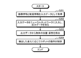
- FIG. 7 is a flowchart showing an example of the control process in the present embodiment.
- the acquisition unit 101 acquires the image information captured by the image pickup unit 301 and the tactile information detected by the tactile sensor 302 as input data (step S201).
- the inference unit 103 inputs the acquired input data to the neural network, and obtains the output data output by the neural network (step S202).
- the detection unit 104 uses the obtained output data to detect a change in at least one of the position and posture of the object 500 (step S203). For example, the detection unit 104 detects changes in output data with respect to a plurality of input data obtained at a plurality of times.
- the motion control unit 105 controls the motion of the robot 300 according to the detected change (step S204).
- the reliability of the image information becomes low due to, for example, an abnormality in the imaging unit 301 or deterioration of the imaging environment (lighting, etc.)
- the contribution of the image information is low due to the processing of the inference unit 103.
- the output data is output.
- the reliability of the tactile information becomes low due to, for example, an abnormality of the tactile sensor 302
- the contribution of the tactile information is reduced by the processing of the inference unit 103, and the output data is output. This makes it possible to estimate the output data indicating at least one of the position and the posture of the object with higher accuracy.
- the detection unit 104 may further include a function of detecting an abnormality in the image pickup unit 301 and the tactile sensor 302 based on at least one of the contribution ⁇ of the image information and the contribution ⁇ of the tactile information.
- a function of detecting an abnormality in the image pickup unit 301 and the tactile sensor 302 based on at least one of the contribution ⁇ of the image information and the contribution ⁇ of the tactile information.
- Any method may be used for detecting (determining) an abnormality based on the degree of contribution, and for example, the following method can be applied.
- the detection unit 104 can obtain one of ⁇ and ⁇ and the other. That is, the detection unit 104 can detect an abnormality of at least one of the image pickup unit 301 and the tactile sensor 302 based on at least one of ⁇ and ⁇ .
- the average value of changes in a plurality of contributions obtained within a predetermined period may be used.
- the motion control unit 105 may stop the operation of the sensor (imaging unit 301, tactile sensor 302) in which the abnormality has occurred. For example, the motion control unit 105 may stop the operation of the image pickup unit 301 when an abnormality of the image pickup unit 301 is detected, and stop the operation of the tactile sensor 302 when an abnormality of the tactile sensor 302 is detected.
- the inference unit 103 may input, for example, information for an abnormality (for example, image information and tactile information in which all pixel values are 0) into the neural network.
- the learning unit 102 may learn the neural network using the learning data for abnormal times. This makes it possible to handle both the case where only some sensors are operated and the case where all the sensors are operated by one neural network.
- the motion control unit 105 may be able to stop the operation of the sensor regardless of the presence or absence of an abnormality. For example, the operation control unit 105 may stop the operation of the specified sensor when the reduction of the calculation cost is specified or when the low power mode is specified. The motion control unit 105 may stop the operation of the image pickup unit 301 and the tactile sensor 302, whichever has the smaller contribution.
- the output control unit 106 may output information (abnormality information) indicating that the abnormality has been detected. Any method may be used to output the abnormality information. For example, a method of displaying the abnormality information on the display device 212 or the like, a method of outputting the abnormality information by emitting light (blinking) of the lighting device, a speaker, or the like. A method of outputting abnormality information by sound using a sound output device and a method of transmitting abnormality information to an external device (administrator terminal, server device, etc.) using a communication device 214 or the like via a network are applied. can do. By outputting the abnormality information, for example, even if the detailed cause of the abnormality is unknown, it is possible to notify that the abnormality has occurred (the state is different from the normal state).
- FIG. 8 is a flowchart showing an example of abnormality detection processing in this modified example.
- the abnormality detection process for example, the degree of contribution obtained when inference using a neural network (step S202) is performed in the control process shown in FIG. 7 is used. Therefore, the control process and the abnormality detection process may be executed in parallel.
- the detection unit 104 acquires the contribution ⁇ of the image information and the contribution ⁇ of the tactile information obtained at the time of inference (step S301). The detection unit 104 determines whether or not there is an abnormality in the image pickup unit 301 and the tactile sensor 302 by using the contributions ⁇ and ⁇ , respectively (step S302).
- the output control unit 106 determines whether or not an abnormality has been detected by the detection unit 104 (step S303). When an abnormality is detected (step S303: Yes), the output control unit 106 outputs abnormality information indicating that the abnormality has occurred (step S304). If no abnormality is detected (step S303: No), the abnormality detection process ends.
- the configuration of the neural network is not limited to this, and may be a neural network that inputs two or more other input information.
- a neural network that further inputs one or more input information other than image information and tactile information, and a neural network that inputs a plurality of input information different from the image information and tactile information may be used. Even when the number of input information is three or more, the degree of contribution may be determined for each input information such as ⁇ , ⁇ , ⁇ , and so on. Further, the abnormality detection process as shown in the modification 1 may be executed using such a neural network.
- the moving body to be operated is not limited to the robot, and may be a vehicle such as an automobile. That is, the present embodiment is applied to, for example, an automatic driving system using a neural network in which image information around the vehicle by the imaging unit 301 and distance information by a LIDAR (Laser Imaging Detection And Ringing) sensor are input information. be able to.
- a neural network in which image information around the vehicle by the imaging unit 301 and distance information by a LIDAR (Laser Imaging Detection And Ringing) sensor are input information. be able to.
- LIDAR Laser Imaging Detection And Ringing
- the input information is not limited to the information input from the sensors such as the image pickup unit 301 and the tactile sensor 302, and may be any information.
- the information input by the user may be used as the input information to the neural network. In this case, if the above modification 1 is applied, for example, it is possible to detect that an invalid input information has been input by the user.
- the designer of the neural network does not need to consider which of the plurality of input information should be used, and for example, the neural network may be constructed so as to input all the plurality of input information. This is because an appropriately learned neural network can output output data by increasing the contribution of necessary input information and decreasing the contribution of unnecessary input information.
- a neural network is constructed so as to input image information of all the imaging units, and the neural network is learned according to the above embodiment. The contribution obtained by learning is verified, and the system is designed so as not to use the imaging unit corresponding to the image information having a low contribution.
- the present embodiment can also improve the efficiency of system integration of a system including a neural network using a plurality of input information.
- the present embodiment includes, for example, the following aspects.
- An inference unit that inputs a plurality of input information about an object gripped by the gripping unit into a neural network and obtains output data indicating at least one of the position and orientation of the object.
- a detection unit that detects an abnormality of each of the plurality of input information based on a plurality of contributions indicating the degree of contribution of each of the plurality of input information to the output data.
- Information processing device equipped with When the change in the contribution degree becomes equal to or greater than the threshold value, the detection unit determines that an abnormality has occurred in the corresponding input information.
- the information processing device according to aspect 1.
- the expression "at least one of a, b and c (one)” or "at least one of a, b or c (one)” is a, b, c, ab, a-. Includes any combination of c, bc, abc. It also covers combinations with a plurality of instances of any of the elements such as aa, abb, aa-b-bc-c. Furthermore, it covers the addition of other elements other than a, b and / or c, such as having abcd.
- Robot system 100 Information processing device 101 Acquisition unit 102 Learning unit 103 Inference unit 104 Detection unit 105 Operation control unit 106 Output control unit 121 Storage unit 200 Controller 204 Memory 206 Hardware processor 208 Storage device 210 Operation device 212 Display device 214 Communication device 222 ROM 224 RAM 300 Robot 301 Imaging unit 302 Tactile sensor 311 Grip unit 400 Sensor 500 Object
Landscapes
- Engineering & Computer Science (AREA)
- Physics & Mathematics (AREA)
- Theoretical Computer Science (AREA)
- General Physics & Mathematics (AREA)
- Evolutionary Computation (AREA)
- Artificial Intelligence (AREA)
- Health & Medical Sciences (AREA)
- Software Systems (AREA)
- Computing Systems (AREA)
- General Health & Medical Sciences (AREA)
- Mathematical Physics (AREA)
- Data Mining & Analysis (AREA)
- General Engineering & Computer Science (AREA)
- Computational Linguistics (AREA)
- Biophysics (AREA)
- Biomedical Technology (AREA)
- Life Sciences & Earth Sciences (AREA)
- Molecular Biology (AREA)
- Computer Vision & Pattern Recognition (AREA)
- Multimedia (AREA)
- Mechanical Engineering (AREA)
- Robotics (AREA)
- Medical Informatics (AREA)
- Automation & Control Theory (AREA)
- Databases & Information Systems (AREA)
- Remote Sensing (AREA)
- Radar, Positioning & Navigation (AREA)
- Aviation & Aerospace Engineering (AREA)
- Game Theory and Decision Science (AREA)
- Business, Economics & Management (AREA)
- Fuzzy Systems (AREA)
- Human Computer Interaction (AREA)
- Manipulator (AREA)
Priority Applications (3)
| Application Number | Priority Date | Filing Date | Title |
|---|---|---|---|
| JP2021529202A JPWO2021002465A1 (https=) | 2019-07-03 | 2020-07-03 | |
| CN202080046345.4A CN114051443A (zh) | 2019-07-03 | 2020-07-03 | 信息处理装置、机器人系统以及信息处理方法 |
| US17/561,440 US20220113724A1 (en) | 2019-07-03 | 2021-12-23 | Information processing device, robot system, and information processing method |
Applications Claiming Priority (2)
| Application Number | Priority Date | Filing Date | Title |
|---|---|---|---|
| JP2019124549 | 2019-07-03 | ||
| JP2019-124549 | 2019-07-03 |
Related Child Applications (1)
| Application Number | Title | Priority Date | Filing Date |
|---|---|---|---|
| US17/561,440 Continuation US20220113724A1 (en) | 2019-07-03 | 2021-12-23 | Information processing device, robot system, and information processing method |
Publications (1)
| Publication Number | Publication Date |
|---|---|
| WO2021002465A1 true WO2021002465A1 (ja) | 2021-01-07 |
Family
ID=74101356
Family Applications (1)
| Application Number | Title | Priority Date | Filing Date |
|---|---|---|---|
| PCT/JP2020/026254 Ceased WO2021002465A1 (ja) | 2019-07-03 | 2020-07-03 | 情報処理装置、ロボットシステム、および、情報処理方法 |
Country Status (4)
| Country | Link |
|---|---|
| US (1) | US20220113724A1 (https=) |
| JP (1) | JPWO2021002465A1 (https=) |
| CN (1) | CN114051443A (https=) |
| WO (1) | WO2021002465A1 (https=) |
Families Citing this family (1)
| Publication number | Priority date | Publication date | Assignee | Title |
|---|---|---|---|---|
| US20210347047A1 (en) * | 2020-05-05 | 2021-11-11 | X Development Llc | Generating robot trajectories using neural networks |
Citations (4)
| Publication number | Priority date | Publication date | Assignee | Title |
|---|---|---|---|---|
| JP2008197078A (ja) * | 2007-02-08 | 2008-08-28 | Nara Institute Of Science & Technology | 触覚センサ及び触覚情報検出方法 |
| JP2016109630A (ja) * | 2014-12-09 | 2016-06-20 | キヤノン株式会社 | 情報処理装置、情報処理方法、プログラム |
| JP2016528483A (ja) * | 2013-06-11 | 2016-09-15 | ソマティス センサー ソリューションズ エルエルシー | 物体を検知するシステム及び方法 |
| JP2018081442A (ja) * | 2016-11-15 | 2018-05-24 | 株式会社Preferred Networks | 学習済モデル生成方法及び信号データ判別装置 |
Family Cites Families (20)
| Publication number | Priority date | Publication date | Assignee | Title |
|---|---|---|---|---|
| JP6287598B2 (ja) * | 2014-06-05 | 2018-03-07 | 株式会社安川電機 | アーク溶接システム、アーク溶接方法および溶接品の製造方法 |
| JP6562619B2 (ja) * | 2014-11-21 | 2019-08-21 | キヤノン株式会社 | 情報処理装置、情報処理方法、プログラム |
| DE102015003696A1 (de) * | 2015-03-20 | 2016-09-22 | Kuka Roboter Gmbh | Freigeben eines Betriebs einer Maschine |
| JP2017126980A (ja) * | 2016-01-08 | 2017-07-20 | オリンパス株式会社 | 情報処理装置、撮像装置、表示装置、情報処理方法、撮像装置の制御方法、表示装置の制御方法、情報処理プログラム、撮像装置の制御プログラム、および表示装置の制御プログラム |
| KR102805829B1 (ko) * | 2016-04-15 | 2025-05-12 | 삼성전자주식회사 | 인터페이스 뉴럴 네트워크 |
| KR101980603B1 (ko) * | 2016-05-20 | 2019-05-22 | 구글 엘엘씨 | 오브젝트(들)를 캡처하는 이미지(들)에 기초하는 그리고 환경에서의 미래 로봇 움직임에 대한 파라미터(들)에 기초하여 로봇 환경에서의 오브젝트(들)의 모션(들)을 예측하는 것과 관련된 머신 학습 방법들 및 장치 |
| US11468290B2 (en) * | 2016-06-30 | 2022-10-11 | Canon Kabushiki Kaisha | Information processing apparatus, information processing method, and non-transitory computer-readable storage medium |
| CN106874914B (zh) * | 2017-01-12 | 2019-05-14 | 华南理工大学 | 一种基于深度卷积神经网络的工业机械臂视觉控制方法 |
| US10796204B2 (en) * | 2017-02-27 | 2020-10-06 | Huawei Technologies Co., Ltd. | Planning system and method for controlling operation of an autonomous vehicle to navigate a planned path |
| JP6546618B2 (ja) * | 2017-05-31 | 2019-07-17 | 株式会社Preferred Networks | 学習装置、学習方法、学習モデル、検出装置及び把持システム |
| CN107139177A (zh) * | 2017-07-03 | 2017-09-08 | 北京康力优蓝机器人科技有限公司 | 一种具备抓取功能的机器人智能末端执行器及控制系统 |
| US10354139B1 (en) * | 2017-09-07 | 2019-07-16 | X Development Llc | Generating and utilizing spatial affordances for an object in robotics applications |
| US11941719B2 (en) * | 2018-01-23 | 2024-03-26 | Nvidia Corporation | Learning robotic tasks using one or more neural networks |
| US11007642B2 (en) * | 2018-10-23 | 2021-05-18 | X Development Llc | Machine learning methods and apparatus for automated robotic placement of secured object in appropriate location |
| US10853670B2 (en) * | 2018-11-21 | 2020-12-01 | Ford Global Technologies, Llc | Road surface characterization using pose observations of adjacent vehicles |
| KR102715879B1 (ko) * | 2019-03-07 | 2024-10-14 | 삼성전자주식회사 | 전자 장치 및 그 제어 방법 |
| WO2020262721A1 (ko) * | 2019-06-25 | 2020-12-30 | 엘지전자 주식회사 | 인공 지능을 이용하여, 복수의 로봇들을 제어하는 관제 시스템 |
| US11195064B2 (en) * | 2019-07-11 | 2021-12-07 | Waymo Llc | Cross-modal sensor data alignment |
| KR20190106944A (ko) * | 2019-08-30 | 2019-09-18 | 엘지전자 주식회사 | 지능형 냉장고 및 그 제어 방법 |
| JP7273692B2 (ja) * | 2019-11-01 | 2023-05-15 | 株式会社東芝 | 制御装置、制御方法およびプログラム |
-
2020
- 2020-07-03 JP JP2021529202A patent/JPWO2021002465A1/ja active Pending
- 2020-07-03 CN CN202080046345.4A patent/CN114051443A/zh not_active Withdrawn
- 2020-07-03 WO PCT/JP2020/026254 patent/WO2021002465A1/ja not_active Ceased
-
2021
- 2021-12-23 US US17/561,440 patent/US20220113724A1/en not_active Abandoned
Patent Citations (4)
| Publication number | Priority date | Publication date | Assignee | Title |
|---|---|---|---|---|
| JP2008197078A (ja) * | 2007-02-08 | 2008-08-28 | Nara Institute Of Science & Technology | 触覚センサ及び触覚情報検出方法 |
| JP2016528483A (ja) * | 2013-06-11 | 2016-09-15 | ソマティス センサー ソリューションズ エルエルシー | 物体を検知するシステム及び方法 |
| JP2016109630A (ja) * | 2014-12-09 | 2016-06-20 | キヤノン株式会社 | 情報処理装置、情報処理方法、プログラム |
| JP2018081442A (ja) * | 2016-11-15 | 2018-05-24 | 株式会社Preferred Networks | 学習済モデル生成方法及び信号データ判別装置 |
Non-Patent Citations (1)
| Title |
|---|
| SHUTOU, KOUJI: "Human Activity Recognition Based on Camera Selection by Boosting", IEICE TECHNICAL REPORT, vol. 108, no. 363, 15 January 2009 (2009-01-15), pages 61 - 66 * |
Also Published As
| Publication number | Publication date |
|---|---|
| CN114051443A (zh) | 2022-02-15 |
| US20220113724A1 (en) | 2022-04-14 |
| JPWO2021002465A1 (https=) | 2021-01-07 |
Similar Documents
| Publication | Publication Date | Title |
|---|---|---|
| JP6946831B2 (ja) | 人物の視線方向を推定するための情報処理装置及び推定方法、並びに学習装置及び学習方法 | |
| US12246456B2 (en) | Image generation device, robot training system, image generation method, and non-transitory computer readable storage medium | |
| US11478926B2 (en) | Operation control device for robot, robot control system, operation control method, control device, processing device and recording medium | |
| TWI802820B (zh) | 機器人控制裝置、方法和儲存媒體 | |
| JP6939111B2 (ja) | 画像認識装置および画像認識方法 | |
| US11679496B2 (en) | Robot controller that controls robot, learned model, method of controlling robot, and storage medium | |
| WO2018102717A1 (en) | Determining structure and motion in images using neural networks | |
| JP2019048365A (ja) | 機械学習装置、ロボットシステム及び機械学習方法 | |
| US12114942B2 (en) | Information processing apparatus, information processing system, and information processing method | |
| CN118661208A (zh) | 处理多模态任务的方法及其装置 | |
| US12541962B2 (en) | Training autoencoders for generating latent representations | |
| KR102436906B1 (ko) | 대상자의 보행 패턴을 식별하는 방법 및 이를 수행하는 전자 장치 | |
| US20220366221A1 (en) | Inference system, inference device, and inference method | |
| US20210241105A1 (en) | Inference apparatus, inference method, and storage medium | |
| WO2021002465A1 (ja) | 情報処理装置、ロボットシステム、および、情報処理方法 | |
| US12350847B2 (en) | Method for controlling a robot for manipulating, in particular picking up, an object | |
| US20190188571A1 (en) | Training neural networks using evolution based strategies and novelty search | |
| JP2010236893A (ja) | 複数の物体間の相対移動を検出する方法 | |
| JP7635823B2 (ja) | 関節点検出装置、学習モデル生成装置、関節点検出方法、学習モデル生成方法、及びプログラム | |
| JP5120024B2 (ja) | 自律移動ロボット及びその障害物識別方法 | |
| US12617083B2 (en) | Manipulation method learning apparatus, manipulation method learning system, manipulation method learning method, and program | |
| WO2022181252A1 (ja) | 関節点検出装置、学習モデル生成装置、関節点検出方法、学習モデル生成方法、及びコンピュータ読み取り可能な記録媒体 | |
| US20240286275A1 (en) | Manipulation method learning apparatus, manipulation method learning system, manipulation method learning method, and program | |
| CN114571450A (zh) | 机器人控制方法、装置及存储介质 | |
| WO2024013895A1 (ja) | 遠隔制御システム、遠隔制御方法、および遠隔制御プログラム |
Legal Events
| Date | Code | Title | Description |
|---|---|---|---|
| 121 | Ep: the epo has been informed by wipo that ep was designated in this application |
Ref document number: 20835069 Country of ref document: EP Kind code of ref document: A1 |
|
| ENP | Entry into the national phase |
Ref document number: 2021529202 Country of ref document: JP Kind code of ref document: A |
|
| NENP | Non-entry into the national phase |
Ref country code: DE |
|
| 122 | Ep: pct application non-entry in european phase |
Ref document number: 20835069 Country of ref document: EP Kind code of ref document: A1 |