WO2021002465A1 - 情報処理装置、ロボットシステム、および、情報処理方法 - Google Patents
情報処理装置、ロボットシステム、および、情報処理方法 Download PDFInfo
- Publication number
- WO2021002465A1 WO2021002465A1 PCT/JP2020/026254 JP2020026254W WO2021002465A1 WO 2021002465 A1 WO2021002465 A1 WO 2021002465A1 JP 2020026254 W JP2020026254 W JP 2020026254W WO 2021002465 A1 WO2021002465 A1 WO 2021002465A1
- Authority
- WO
- WIPO (PCT)
- Prior art keywords
- information
- contribution
- information processing
- tactile
- abnormality
- Prior art date
Links
- 230000010365 information processing Effects 0.000 title claims abstract description 71
- 238000003672 processing method Methods 0.000 title claims description 11
- 238000013528 artificial neural network Methods 0.000 claims description 61
- 230000005856 abnormality Effects 0.000 claims description 53
- 238000001514 detection method Methods 0.000 claims description 38
- 238000003384 imaging method Methods 0.000 claims description 27
- 230000008859 change Effects 0.000 claims description 19
- 230000002159 abnormal effect Effects 0.000 claims description 3
- 230000004044 response Effects 0.000 claims description 2
- 230000013016 learning Effects 0.000 description 68
- 238000000034 method Methods 0.000 description 35
- 230000008569 process Effects 0.000 description 24
- 238000013527 convolutional neural network Methods 0.000 description 12
- 230000006870 function Effects 0.000 description 11
- 238000010586 diagram Methods 0.000 description 10
- 238000004891 communication Methods 0.000 description 7
- 230000015654 memory Effects 0.000 description 6
- 230000004048 modification Effects 0.000 description 6
- 238000012986 modification Methods 0.000 description 6
- 238000012545 processing Methods 0.000 description 6
- 238000013459 approach Methods 0.000 description 2
- 238000004364 calculation method Methods 0.000 description 2
- 230000004927 fusion Effects 0.000 description 2
- 239000000463 material Substances 0.000 description 2
- 239000004065 semiconductor Substances 0.000 description 2
- 230000004397 blinking Effects 0.000 description 1
- 238000004422 calculation algorithm Methods 0.000 description 1
- 238000004590 computer program Methods 0.000 description 1
- 238000007796 conventional method Methods 0.000 description 1
- 230000007423 decrease Effects 0.000 description 1
- 230000003247 decreasing effect Effects 0.000 description 1
- 230000006866 deterioration Effects 0.000 description 1
- 238000006073 displacement reaction Methods 0.000 description 1
- 230000006872 improvement Effects 0.000 description 1
- 230000010354 integration Effects 0.000 description 1
- 230000009467 reduction Effects 0.000 description 1
- 230000006403 short-term memory Effects 0.000 description 1
- 230000001360 synchronised effect Effects 0.000 description 1
- 238000013519 translation Methods 0.000 description 1
- 230000032258 transport Effects 0.000 description 1
- 239000013598 vector Substances 0.000 description 1
Images


Classifications
-
- B—PERFORMING OPERATIONS; TRANSPORTING
- B25—HAND TOOLS; PORTABLE POWER-DRIVEN TOOLS; MANIPULATORS
- B25J—MANIPULATORS; CHAMBERS PROVIDED WITH MANIPULATION DEVICES
- B25J9/00—Programme-controlled manipulators
- B25J9/16—Programme controls
- B25J9/1656—Programme controls characterised by programming, planning systems for manipulators
- B25J9/1661—Programme controls characterised by programming, planning systems for manipulators characterised by task planning, object-oriented languages
-
- G—PHYSICS
- G05—CONTROLLING; REGULATING
- G05D—SYSTEMS FOR CONTROLLING OR REGULATING NON-ELECTRIC VARIABLES
- G05D1/00—Control of position, course, altitude or attitude of land, water, air or space vehicles, e.g. using automatic pilots
- G05D1/0088—Control of position, course, altitude or attitude of land, water, air or space vehicles, e.g. using automatic pilots characterized by the autonomous decision making process, e.g. artificial intelligence, predefined behaviours
-
- G—PHYSICS
- G06—COMPUTING; CALCULATING OR COUNTING
- G06T—IMAGE DATA PROCESSING OR GENERATION, IN GENERAL
- G06T7/00—Image analysis
- G06T7/70—Determining position or orientation of objects or cameras
- G06T7/73—Determining position or orientation of objects or cameras using feature-based methods
- G06T7/74—Determining position or orientation of objects or cameras using feature-based methods involving reference images or patches
-
- B—PERFORMING OPERATIONS; TRANSPORTING
- B25—HAND TOOLS; PORTABLE POWER-DRIVEN TOOLS; MANIPULATORS
- B25J—MANIPULATORS; CHAMBERS PROVIDED WITH MANIPULATION DEVICES
- B25J13/00—Controls for manipulators
- B25J13/08—Controls for manipulators by means of sensing devices, e.g. viewing or touching devices
-
- B—PERFORMING OPERATIONS; TRANSPORTING
- B25—HAND TOOLS; PORTABLE POWER-DRIVEN TOOLS; MANIPULATORS
- B25J—MANIPULATORS; CHAMBERS PROVIDED WITH MANIPULATION DEVICES
- B25J19/00—Accessories fitted to manipulators, e.g. for monitoring, for viewing; Safety devices combined with or specially adapted for use in connection with manipulators
- B25J19/02—Sensing devices
-
- B—PERFORMING OPERATIONS; TRANSPORTING
- B25—HAND TOOLS; PORTABLE POWER-DRIVEN TOOLS; MANIPULATORS
- B25J—MANIPULATORS; CHAMBERS PROVIDED WITH MANIPULATION DEVICES
- B25J9/00—Programme-controlled manipulators
- B25J9/16—Programme controls
- B25J9/1602—Programme controls characterised by the control system, structure, architecture
- B25J9/161—Hardware, e.g. neural networks, fuzzy logic, interfaces, processor
-
- G—PHYSICS
- G01—MEASURING; TESTING
- G01B—MEASURING LENGTH, THICKNESS OR SIMILAR LINEAR DIMENSIONS; MEASURING ANGLES; MEASURING AREAS; MEASURING IRREGULARITIES OF SURFACES OR CONTOURS
- G01B21/00—Measuring arrangements or details thereof, where the measuring technique is not covered by the other groups of this subclass, unspecified or not relevant
-
- G—PHYSICS
- G06—COMPUTING; CALCULATING OR COUNTING
- G06N—COMPUTING ARRANGEMENTS BASED ON SPECIFIC COMPUTATIONAL MODELS
- G06N3/00—Computing arrangements based on biological models
- G06N3/02—Neural networks
- G06N3/04—Architecture, e.g. interconnection topology
- G06N3/045—Combinations of networks
-
- G—PHYSICS
- G06—COMPUTING; CALCULATING OR COUNTING
- G06N—COMPUTING ARRANGEMENTS BASED ON SPECIFIC COMPUTATIONAL MODELS
- G06N3/00—Computing arrangements based on biological models
- G06N3/02—Neural networks
- G06N3/08—Learning methods
- G06N3/084—Backpropagation, e.g. using gradient descent
-
- G—PHYSICS
- G06—COMPUTING; CALCULATING OR COUNTING
- G06T—IMAGE DATA PROCESSING OR GENERATION, IN GENERAL
- G06T7/00—Image analysis
- G06T7/70—Determining position or orientation of objects or cameras
-
- G—PHYSICS
- G06—COMPUTING; CALCULATING OR COUNTING
- G06V—IMAGE OR VIDEO RECOGNITION OR UNDERSTANDING
- G06V10/00—Arrangements for image or video recognition or understanding
- G06V10/70—Arrangements for image or video recognition or understanding using pattern recognition or machine learning
- G06V10/82—Arrangements for image or video recognition or understanding using pattern recognition or machine learning using neural networks
-
- G—PHYSICS
- G06—COMPUTING; CALCULATING OR COUNTING
- G06V—IMAGE OR VIDEO RECOGNITION OR UNDERSTANDING
- G06V20/00—Scenes; Scene-specific elements
- G06V20/50—Context or environment of the image
- G06V20/56—Context or environment of the image exterior to a vehicle by using sensors mounted on the vehicle
-
- G—PHYSICS
- G06—COMPUTING; CALCULATING OR COUNTING
- G06T—IMAGE DATA PROCESSING OR GENERATION, IN GENERAL
- G06T2207/00—Indexing scheme for image analysis or image enhancement
- G06T2207/20—Special algorithmic details
- G06T2207/20081—Training; Learning
-
- G—PHYSICS
- G06—COMPUTING; CALCULATING OR COUNTING
- G06T—IMAGE DATA PROCESSING OR GENERATION, IN GENERAL
- G06T2207/00—Indexing scheme for image analysis or image enhancement
- G06T2207/20—Special algorithmic details
- G06T2207/20084—Artificial neural networks [ANN]
-
- G—PHYSICS
- G06—COMPUTING; CALCULATING OR COUNTING
- G06T—IMAGE DATA PROCESSING OR GENERATION, IN GENERAL
- G06T2207/00—Indexing scheme for image analysis or image enhancement
- G06T2207/30—Subject of image; Context of image processing
- G06T2207/30248—Vehicle exterior or interior
- G06T2207/30252—Vehicle exterior; Vicinity of vehicle
Definitions
- An embodiment of the present invention relates to an information processing device, a robot system, and an information processing method.
- a robot system that grips and transports an object by a grip (hand part, etc.) is known.
- Such a robot system estimates, for example, the position and posture of an object from image information obtained by capturing an image of the object, and controls the gripping of the object based on the estimated information.
- the problem to be solved by the invention is to make it possible to estimate at least one of the position and the posture of the object with higher accuracy.
- the information processing device includes an acquisition unit and an inference unit.
- the acquisition unit acquires image information of the object and tactile information indicating a contact state between the gripping unit that grips the object and the object.
- the inference unit obtains output data indicating at least one of the position and orientation of the object based on at least one of the first contribution of the image information and the second contribution of the tactile information.
- FIG. 1 is a diagram showing a hardware configuration example of a robot system including the information processing device of the embodiment.
- FIG. 2 is a diagram showing a configuration example of the robot.
- FIG. 3 is a hardware block diagram of the information processing device.
- FIG. 4 is a functional block diagram showing an example of the functional configuration of the information processing device.
- FIG. 5 is a diagram showing a configuration example of a neural network.
- FIG. 6 is a flowchart showing an example of the learning process in the embodiment.
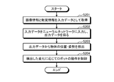
- FIG. 7 is a flowchart showing an example of the control process in the embodiment.
- FIG. 8 is a flowchart showing an example of the abnormality detection process in the modified example.
- FIG. 1 is a diagram showing a hardware configuration example of the robot system 1 including the information processing device 100 of the present embodiment.
- the robot system 1 includes an information processing device 100, a controller 200, a robot 300, and a sensor 400.
- the robot 300 is an example of a moving body that moves by controlling at least one of its position and posture (orbit) by the information processing device 100.
- the robot 300 includes, for example, a grip portion (grip device) for gripping an object, a plurality of links, a plurality of joints, and a plurality of drive devices (motors and the like) for driving each of the joints.
- a robot 300 having at least a gripping portion for gripping an object and moving the gripped object will be described as an example.
- FIG. 2 is a diagram showing a configuration example of the robot 300 configured in this way.
- the robot 300 includes a grip portion 311, an imaging unit (imaging device) 301, and a tactile sensor 302.
- the grip portion 311 grips the moving object 500.
- the imaging unit 301 is an imaging device that images an object 500 and outputs image information.
- the imaging unit 301 does not need to be provided in the robot 300, and may be installed outside the robot 300.
- the tactile sensor 302 is a sensor that acquires tactile information indicating a contact state between the grip portion 311 and the object 500.
- the tactile sensor 302 is, for example, a sensor that brings a gel-like material into contact with an object 500 and outputs image information captured as tactile information by an imaging device different from the imaging unit 301 for the displacement of the gel-like material caused by the contact. Is.
- the tactile information may be information representing the contact state in an image format.
- the tactile sensor 302 is not limited to this, and may be any sensor.
- the tactile sensor 302 may be a sensor that detects tactile information using at least one of the pressure, resistance value, and capacitance generated by the contact between the grip portion 311 and the object 500.
- the applicable robot is not limited to this, and any robot (moving body) may be used.
- it may be a robot having one joint and a link, a mobile manipulator, and a mobile trolley.
- the robot may be provided with a drive device for moving the entire robot in parallel in an arbitrary direction in the real space.
- the moving body may be an object whose overall position changes in this way, or an object in which a part of the position is fixed and at least one of the position and the posture of the other part changes.
- the sensor 400 detects information to be used for controlling the operation of the robot 300.
- the sensor 400 is, for example, a depth sensor (depth sensor) that detects depth information up to an object 500.
- the sensor 400 is not limited to the depth sensor. Further, the sensor 400 may not be provided.
- the sensor 400 may be an imaging unit 301 installed outside the robot 300 as described above.
- the robot 300 may be configured to also include a sensor 400 such as a depth sensor.
- the controller 200 controls the drive of the robot 300 in response to an instruction from the information processing device 100.
- the controller 200 controls the grip portion 311 of the robot 300 and a driving device (motor or the like) for driving joints or the like so as to rotate in the rotation direction and rotation speed specified by the information processing device 100.
- the information processing device 100 is connected to the controller 200, the robot 300, and the sensor 400, and controls the entire robot system 1.
- the information processing device 100 controls the operation of the robot 300.
- the control of the operation of the robot 300 includes a process of operating (moving) the robot 300 based on at least one of the position and the posture of the object 500.
- the information processing device 100 outputs an operation command for operating the robot 300 to the controller 200.
- the information processing device 100 may have a function of learning a neural network for estimating (inferring) at least one of the position and the posture of the object 500. In this case, the information processing device 100 also functions as a learning device for learning the neural network.
- FIG. 3 is a hardware block diagram of the information processing device 100.
- the information processing device 100 is realized by a hardware configuration similar to that of a general computer (information processing device) as shown in FIG.
- the information processing device 100 may be realized by one computer as shown in FIG. 3, or may be realized by a plurality of computers that operate in cooperation with each other.
- the information processing device 100 includes a memory 204, one or more hardware processors 206, a storage device 208, an operating device 210, a display device 212, and a communication device 214. Each part is connected by a bus.
- the hardware processor 206 may be included in a plurality of computers operating in cooperation with each other.
- Memory 204 includes, for example, ROM 222 and RAM 224.
- the ROM 222 stores the program used for controlling the information processing apparatus 100, various setting information, and the like in a non-rewritable manner.
- the RAM 224 is a volatile storage medium such as SDRAM (Synchronous Dynamic Random Access Memory).
- SDRAM Serial Dynamic Random Access Memory
- the RAM 224 serves as a work area for one or more hardware processors 206.
- One or more hardware processors 206 are connected to memory 204 (ROM 222 and RAM 224) via a bus.
- the one or more hardware processors 206 may be, for example, one or a plurality of CPUs (Central Processing Units) or one or a plurality of GPUs (Graphics Processing Units). Further, the one or more hardware processors 206 may be a semiconductor device or the like including a dedicated processing circuit for realizing a neural network.
- One or a plurality of hardware processors 206 execute various processes in cooperation with various programs stored in ROM 222 or the storage device 208 in advance using a predetermined area of the RAM 224 as a work area, and perform various processes in each part constituting the information processing device 100. Control the operation comprehensively. Further, one or more hardware processors 206 control the operation device 210, the display device 212, the communication device 214, and the like in cooperation with the program stored in the ROM 222 or the storage device 208 in advance.
- the storage device 208 is a rewritable recording medium such as a semiconductor storage medium such as a flash memory or a magnetically or optically recordable storage medium.
- the storage device 208 stores a program used for controlling the information processing device 100, various setting information, and the like.
- the operation device 210 is an input device such as a mouse and a keyboard.
- the operation device 210 receives the information input from the user and outputs the received information to one or more hardware processors 206.
- the display device 212 displays information to the user.
- the display device 212 receives information or the like from one or more hardware processors 206, and displays the received information.
- the information processing device 100 does not have to include the display device 212.
- the communication device 214 communicates with an external device and transmits / receives information via a network or the like.
- the program executed by the information processing apparatus 100 of the present embodiment is a file in an installable format or an executable format, and is a computer such as a CD-ROM, a flexible disk (FD), a CD-R, or a DVD (Digital Versatile Disk). It is recorded on a readable recording medium and provided as a computer program product.
- the program executed by the information processing apparatus 100 of the present embodiment may be stored on a computer connected to a network such as the Internet and provided by downloading via the network. Further, the program executed by the information processing apparatus 100 of the present embodiment may be configured to be provided or distributed via a network such as the Internet. Further, the program executed by the information processing apparatus 100 of the present embodiment may be configured to be provided by incorporating it into a ROM or the like in advance.
- the program executed by the information processing device 100 can make the computer function as each part of the information processing device 100 described later.
- the computer can read and execute a program on the main memory from a computer-readable storage medium by the hardware processor 206.
- the hardware configuration shown in FIG. 1 is an example, and is not limited to this.
- One device may be configured to include a part or all of the information processing device 100, the controller 200, the robot 300, and the sensor 400.
- the robot 300 may be configured to also include the functions of the information processing device 100, the controller 200, and the sensor 400.
- the information processing apparatus 100 may be configured to have one or both functions of the controller 200 and the sensor 400.
- the information processing device 100 can also function as a learning device, the information processing device 100 and the learning device may be realized by physically different devices.
- FIG. 4 is a functional block diagram showing an example of the functional configuration of the information processing apparatus 100.
- the information processing apparatus 100 includes an acquisition unit 101, a learning unit 102, an inference unit 103, a detection unit 104, an operation control unit 105, an output control unit 106, and a storage unit 121. It has.
- the acquisition unit 101 acquires various information used in various processes executed by the information processing device 100.
- the acquisition unit 101 acquires learning data for learning a neural network.
- the learning data can be acquired by any method, but the acquisition unit 101 acquires, for example, the learning data created in advance from an external device via a network or the like, or from a storage medium.
- the learning unit 102 learns the neural network using the learning data.
- the neural network inputs, for example, the image information of the object 500 imaged by the imaging unit 301 and the tactile information obtained by the tactile sensor 302, and outputs output data which is at least one of the position and orientation of the object 500. ..
- the learning data is, for example, data in which image information, tactile information, and at least one of the position and posture of the object 500 (correct answer data) are associated with each other.
- a neural network that outputs output data indicating at least one of the position and orientation of the object 500 can be obtained with respect to the input image information and tactile information.
- the output data indicating at least one of the position and the posture includes the output data indicating the position, the output data indicating the posture, and the output data indicating both the position and the posture.
- the inference unit 103 executes inference using the learned neural network. For example, the inference unit 103 inputs image information and tactile information to the neural network, and obtains output data indicating at least one of the position and orientation of the object 500 output by the neural network.
- the detection unit 104 detects information used for controlling the operation of the robot 300. For example, the detection unit 104 detects a change in at least one of the position and the posture of the object 500 by using the plurality of output data obtained by the inference unit 103. The detection unit 104 may detect a relative change in at least one of the position and posture of the object 500 obtained thereafter with respect to at least one of the position and posture of the object 500 at the time when the gripping of the object 500 is started. .. Relative changes include changes caused by the rotation or translation of the object 500 with respect to the grip 311. Information on such relative changes can be used for in-hand manipulation or the like that controls at least one of the position and orientation of the object while holding the object 500.
- the imaging unit 301 When the imaging unit 301 is installed outside the robot 300, it may be configured to obtain the position information of the robot 300 with respect to the imaging unit 301. As a result, the position and orientation of the object 500 in absolute coordinates can be obtained more easily.
- the motion control unit 105 controls the motion of the robot 300.
- the motion control unit 105 refers to at least one change in the position and posture of the object 500 detected by the detection unit 104, and positions the grip unit 311 and the robot 300 so that the object 500 is in the target position and posture. And so on. More specifically, the motion control unit 105 generates an motion command for operating the robot 300 so that the object 500 has a target position and posture, and transmits the motion command to the controller 200 to cause the robot 300. To operate.
- the output control unit 106 controls the output of various information. For example, the output control unit 106 controls a process of displaying information on the display device 212 and a process of transmitting and receiving information via a network using the communication device 214.
- the storage unit 121 stores various information used in the information processing device 100.
- the storage unit 121 stores the parameters of the neural network (weighting coefficient, bias, etc.) and the learning data for learning the neural network.
- the storage unit 121 is realized by, for example, the storage device 208 of FIG.
- Each of the above units is realized by, for example, one or more hardware processors 206.
- each of the above parts may be realized by having one or a plurality of CPUs execute a program, that is, by software.
- Each of the above parts may be realized by a hardware processor such as a dedicated IC (Integrated Circuit), that is, hardware.
- Each of the above parts may be realized by using software and hardware in combination. When a plurality of processors are used, each processor may realize one of each part, or may realize two or more of each part.
- FIG. 5 is a diagram showing a configuration example of a neural network.
- a configuration of a neural network including CNN Convolutional Neural Network
- a neural network other than CNN may be used.
- the neural network shown in FIG. 5 is an example, and is not limited to this.
- the neural network includes CNN501, CNN502, coupler 503, multiplier 504, multiplier 505, and coupler 506.
- CNN 501 and 502 are CNNs for inputting image information and tactile information, respectively.
- the combiner 503 concatenates the output of CNN501 and the output of CNN502.
- the coupler 503 may be configured as a neural network.
- the coupler 503 can be, but is not limited to, a fully coupled neural network.
- the coupler 503 is, for example, a neural network that inputs the output of CNN501 and the output of CNN502 and outputs ⁇ and ⁇ (two-dimensional information).
- the combiner 503 may control the output range by using, for example, a ReLu function, a sigmoid function, a softmax function, and the like.
- the coupler 503 inputs the output of the CNN corresponding to each sensor, and outputs N-dimensional or (N-1) -dimensional information ( ⁇ , ⁇ , ⁇ , ..., Etc.). It may be configured.
- the multiplier 504 multiplies the output of the CNN 501 by ⁇ .
- the multiplier 505 multiplies the output of the CNN 502 by ⁇ .
- ⁇ and ⁇ are values (for example, vectors) calculated based on the output of the coupler 503.
- ⁇ and ⁇ are the contribution of image information (first contribution) and the contribution of tactile information (second contribution) to the final output data (at least one of position and orientation) of the neural network, respectively. It is a value corresponding to.
- ⁇ and ⁇ can be calculated by including an intermediate layer in the neural network that inputs the output of the coupler 503 and outputs ⁇ and ⁇ .
- ⁇ and ⁇ are values (usage ratios) indicating how much image information and tactile information are used for calculating output data, weights of image information and tactile information, and reliability of image information and tactile information. It can also be interpreted as degree, etc.
- attention for example, a value indicating which part of the image to pay attention to is calculated.
- a technique for example, even in a situation where the reliability (or data correlation) of input information (image information, etc.) is low, there may be a problem of paying attention to a part of data to which attention is applied.
- the degree of contribution (usage ratio, weight, or reliability) of the image information and the tactile information to the output data is calculated. For example, when the reliability of image information is low, ⁇ approaches 0.
- the multiplication result of the value of ⁇ and the output from CNN501 is used when calculating the final output data. This means that if the image information is unreliable, the usage rate of the image information when calculating the final output data decreases. With such a function, the position and posture of the object can be estimated with higher accuracy.
- the output of the CNN 501 for the coupler 503 and the output of the CNN 501 for the multiplier 504 may be the same or different.
- the number of dimensions of each output from CNN501 may be different from each other.
- the output of the CNN 502 to the coupler 503 and the output of the CNN 502 to the multiplier 505 may be the same or different.
- the number of dimensions of each output from CNN502 may be different from each other.
- the combiner 506 combines the output of the multiplier 504 and the output of the multiplier 505, and outputs the combined result as output data indicating at least one of the position and the posture of the object 500.
- the coupler 506 may be configured as a neural network.
- the coupler 503 can be a fully coupled neural network and an LSTM (Long short term memory) neural network, but is not limited thereto.
- the coupler 503 When the coupler 503 outputs only ⁇ or only ⁇ as described above, it can be interpreted that output data can be obtained using only ⁇ or only ⁇ . That is, the inference unit 103 can obtain output data based on at least one of the contribution ⁇ of the image information and the contribution ⁇ of the tactile information.
- FIG. 6 is a flowchart showing an example of the learning process in the present embodiment.
- the acquisition unit 101 acquires learning data including image information and tactile information (step S101).
- the acquisition unit 101 acquires the learning data acquired from, for example, an external device via a network or the like and stored in the storage unit 121.
- the learning process is repeatedly executed a plurality of times.
- the acquisition unit 101 may acquire a part of the plurality of learning data as learning data (batch) used for each learning.
- the learning unit 102 inputs the image information and the tactile information included in the acquired learning data into the neural network, and obtains the output data output by the neural network (step S102).
- the learning unit 102 updates the parameters of the neural network using the output data (step S103). For example, the learning unit 102 updates the parameters of the neural network so as to minimize the error (E1) between the output data and the correct answer data (correct answer data indicating at least one of the position and the posture of the object 500) included in the learning data. To do.
- the learning unit 102 may use any algorithm for learning, and for example, the learning unit 102 can perform learning by using an error backpropagation method.
- the learning unit 102 determines whether or not to end learning (step S104). For example, the learning unit 102 determines the end of learning depending on whether all the learning data has been processed, the magnitude of the error improvement is smaller than the threshold value, or the number of learnings has reached the upper limit. judge.
- step S104: No If the learning is not completed (step S104: No), the process returns to step S101 and the process is repeated for the new learning data. When it is determined that the learning is completed (step S104: Yes), the learning process is terminated.
- a neural network that outputs output data indicating at least one of the position and orientation of the object 500 can be obtained with respect to the input data including the image information and the tactile information.
- This neural network can be used not only to output output data but also to obtain contributions ⁇ and ⁇ from the intermediate layer.
- the present embodiment it is possible to change the type of learning data that contributes to learning according to the progress of learning. For example, in the initial stage of learning, the contribution of image information increases, and the contribution of tactile information increases in the middle, so that learning is performed from a part that is easy to learn, and learning can proceed more efficiently. As a result, learning can be performed in a shorter time than general neural network learning (multimodal learning that does not use attention) in which a plurality of input information is input.
- general neural network learning multimodal learning that does not use attention
- FIG. 7 is a flowchart showing an example of the control process in the present embodiment.
- the acquisition unit 101 acquires the image information captured by the image pickup unit 301 and the tactile information detected by the tactile sensor 302 as input data (step S201).
- the inference unit 103 inputs the acquired input data to the neural network, and obtains the output data output by the neural network (step S202).
- the detection unit 104 uses the obtained output data to detect a change in at least one of the position and posture of the object 500 (step S203). For example, the detection unit 104 detects changes in output data with respect to a plurality of input data obtained at a plurality of times.
- the motion control unit 105 controls the motion of the robot 300 according to the detected change (step S204).
- the reliability of the image information becomes low due to, for example, an abnormality in the imaging unit 301 or deterioration of the imaging environment (lighting, etc.)
- the contribution of the image information is low due to the processing of the inference unit 103.
- the output data is output.
- the reliability of the tactile information becomes low due to, for example, an abnormality of the tactile sensor 302
- the contribution of the tactile information is reduced by the processing of the inference unit 103, and the output data is output. This makes it possible to estimate the output data indicating at least one of the position and the posture of the object with higher accuracy.
- the detection unit 104 may further include a function of detecting an abnormality in the image pickup unit 301 and the tactile sensor 302 based on at least one of the contribution ⁇ of the image information and the contribution ⁇ of the tactile information.
- a function of detecting an abnormality in the image pickup unit 301 and the tactile sensor 302 based on at least one of the contribution ⁇ of the image information and the contribution ⁇ of the tactile information.
- Any method may be used for detecting (determining) an abnormality based on the degree of contribution, and for example, the following method can be applied.
- the detection unit 104 can obtain one of ⁇ and ⁇ and the other. That is, the detection unit 104 can detect an abnormality of at least one of the image pickup unit 301 and the tactile sensor 302 based on at least one of ⁇ and ⁇ .
- the average value of changes in a plurality of contributions obtained within a predetermined period may be used.
- the motion control unit 105 may stop the operation of the sensor (imaging unit 301, tactile sensor 302) in which the abnormality has occurred. For example, the motion control unit 105 may stop the operation of the image pickup unit 301 when an abnormality of the image pickup unit 301 is detected, and stop the operation of the tactile sensor 302 when an abnormality of the tactile sensor 302 is detected.
- the inference unit 103 may input, for example, information for an abnormality (for example, image information and tactile information in which all pixel values are 0) into the neural network.
- the learning unit 102 may learn the neural network using the learning data for abnormal times. This makes it possible to handle both the case where only some sensors are operated and the case where all the sensors are operated by one neural network.
- the motion control unit 105 may be able to stop the operation of the sensor regardless of the presence or absence of an abnormality. For example, the operation control unit 105 may stop the operation of the specified sensor when the reduction of the calculation cost is specified or when the low power mode is specified. The motion control unit 105 may stop the operation of the image pickup unit 301 and the tactile sensor 302, whichever has the smaller contribution.
- the output control unit 106 may output information (abnormality information) indicating that the abnormality has been detected. Any method may be used to output the abnormality information. For example, a method of displaying the abnormality information on the display device 212 or the like, a method of outputting the abnormality information by emitting light (blinking) of the lighting device, a speaker, or the like. A method of outputting abnormality information by sound using a sound output device and a method of transmitting abnormality information to an external device (administrator terminal, server device, etc.) using a communication device 214 or the like via a network are applied. can do. By outputting the abnormality information, for example, even if the detailed cause of the abnormality is unknown, it is possible to notify that the abnormality has occurred (the state is different from the normal state).
- FIG. 8 is a flowchart showing an example of abnormality detection processing in this modified example.
- the abnormality detection process for example, the degree of contribution obtained when inference using a neural network (step S202) is performed in the control process shown in FIG. 7 is used. Therefore, the control process and the abnormality detection process may be executed in parallel.
- the detection unit 104 acquires the contribution ⁇ of the image information and the contribution ⁇ of the tactile information obtained at the time of inference (step S301). The detection unit 104 determines whether or not there is an abnormality in the image pickup unit 301 and the tactile sensor 302 by using the contributions ⁇ and ⁇ , respectively (step S302).
- the output control unit 106 determines whether or not an abnormality has been detected by the detection unit 104 (step S303). When an abnormality is detected (step S303: Yes), the output control unit 106 outputs abnormality information indicating that the abnormality has occurred (step S304). If no abnormality is detected (step S303: No), the abnormality detection process ends.
- the configuration of the neural network is not limited to this, and may be a neural network that inputs two or more other input information.
- a neural network that further inputs one or more input information other than image information and tactile information, and a neural network that inputs a plurality of input information different from the image information and tactile information may be used. Even when the number of input information is three or more, the degree of contribution may be determined for each input information such as ⁇ , ⁇ , ⁇ , and so on. Further, the abnormality detection process as shown in the modification 1 may be executed using such a neural network.
- the moving body to be operated is not limited to the robot, and may be a vehicle such as an automobile. That is, the present embodiment is applied to, for example, an automatic driving system using a neural network in which image information around the vehicle by the imaging unit 301 and distance information by a LIDAR (Laser Imaging Detection And Ringing) sensor are input information. be able to.
- a neural network in which image information around the vehicle by the imaging unit 301 and distance information by a LIDAR (Laser Imaging Detection And Ringing) sensor are input information. be able to.
- LIDAR Laser Imaging Detection And Ringing
- the input information is not limited to the information input from the sensors such as the image pickup unit 301 and the tactile sensor 302, and may be any information.
- the information input by the user may be used as the input information to the neural network. In this case, if the above modification 1 is applied, for example, it is possible to detect that an invalid input information has been input by the user.
- the designer of the neural network does not need to consider which of the plurality of input information should be used, and for example, the neural network may be constructed so as to input all the plurality of input information. This is because an appropriately learned neural network can output output data by increasing the contribution of necessary input information and decreasing the contribution of unnecessary input information.
- a neural network is constructed so as to input image information of all the imaging units, and the neural network is learned according to the above embodiment. The contribution obtained by learning is verified, and the system is designed so as not to use the imaging unit corresponding to the image information having a low contribution.
- the present embodiment can also improve the efficiency of system integration of a system including a neural network using a plurality of input information.
- the present embodiment includes, for example, the following aspects.
- An inference unit that inputs a plurality of input information about an object gripped by the gripping unit into a neural network and obtains output data indicating at least one of the position and orientation of the object.
- a detection unit that detects an abnormality of each of the plurality of input information based on a plurality of contributions indicating the degree of contribution of each of the plurality of input information to the output data.
- Information processing device equipped with When the change in the contribution degree becomes equal to or greater than the threshold value, the detection unit determines that an abnormality has occurred in the corresponding input information.
- the information processing device according to aspect 1.
- the expression "at least one of a, b and c (one)” or "at least one of a, b or c (one)” is a, b, c, ab, a-. Includes any combination of c, bc, abc. It also covers combinations with a plurality of instances of any of the elements such as aa, abb, aa-b-bc-c. Furthermore, it covers the addition of other elements other than a, b and / or c, such as having abcd.
- Robot system 100 Information processing device 101 Acquisition unit 102 Learning unit 103 Inference unit 104 Detection unit 105 Operation control unit 106 Output control unit 121 Storage unit 200 Controller 204 Memory 206 Hardware processor 208 Storage device 210 Operation device 212 Display device 214 Communication device 222 ROM 224 RAM 300 Robot 301 Imaging unit 302 Tactile sensor 311 Grip unit 400 Sensor 500 Object
Landscapes
- Engineering & Computer Science (AREA)
- Physics & Mathematics (AREA)
- Theoretical Computer Science (AREA)
- General Physics & Mathematics (AREA)
- Evolutionary Computation (AREA)
- Artificial Intelligence (AREA)
- Health & Medical Sciences (AREA)
- Software Systems (AREA)
- Computing Systems (AREA)
- General Health & Medical Sciences (AREA)
- Computer Vision & Pattern Recognition (AREA)
- Multimedia (AREA)
- Robotics (AREA)
- Mechanical Engineering (AREA)
- Mathematical Physics (AREA)
- Medical Informatics (AREA)
- Automation & Control Theory (AREA)
- General Engineering & Computer Science (AREA)
- Molecular Biology (AREA)
- Data Mining & Analysis (AREA)
- Computational Linguistics (AREA)
- Biophysics (AREA)
- Biomedical Technology (AREA)
- Life Sciences & Earth Sciences (AREA)
- Databases & Information Systems (AREA)
- Radar, Positioning & Navigation (AREA)
- Business, Economics & Management (AREA)
- Game Theory and Decision Science (AREA)
- Aviation & Aerospace Engineering (AREA)
- Remote Sensing (AREA)
- Fuzzy Systems (AREA)
- Human Computer Interaction (AREA)
- Manipulator (AREA)
Abstract
実施形態にかかる情報処理装置は、取得部と、推論部と、を備える。取得部は、物体の画像情報、および、物体を把持する把持部と物体との接触状態を表す触覚情報を取得する。推論部は、画像情報の第1寄与度および触覚情報の第2寄与度の少なくとも一方に基づいて、物体の位置および姿勢の少なくとも一方を示す出力データを得る。
Description
本発明の実施形態は、情報処理装置、ロボットシステム、および、情報処理方法に関する。
把持部(ハンド部など)により物体を把持して運搬するロボットシステムが知られている。このようなロボットシステムは、例えば、物体を撮像した画像情報などから物体の位置および姿勢などを推定し、推定した情報に基づいて物体の把持を制御する。
Jaekyum Kim, et al., "Robust Deep Multi-modal Learning Based on Gated Information Fusion Network", arXiv: 1807.06233, 2 Nov 2018.
Arevalo, John, et al., "GATED MULTIMODAL UNITS FOR INFORMATION FUSION",[online]、 retrieved from the Internet: <URL:https://openreview.net/pdf?id=Hy-2G6ile>
発明が解決しようとする課題は、物体の位置および姿勢の少なくとも一方をより高精度に推定可能とすることにある。
実施形態にかかる情報処理装置は、取得部と、推論部と、を備える。取得部は、物体の画像情報、および、物体を把持する把持部と物体との接触状態を表す触覚情報を取得する。推論部は、画像情報の第1寄与度および触覚情報の第2寄与度の少なくとも一方に基づいて、物体の位置および姿勢の少なくとも一方を示す出力データを得る。
以下、図面を参照しながら実施形態について詳細に説明する。
図1は、本実施形態の情報処理装置100を含むロボットシステム1のハードウェア構成例を示す図である。図1に示すように、ロボットシステム1は、情報処理装置100と、コントローラ200と、ロボット300と、センサ400と、を備えている。
ロボット300は、情報処理装置100によって位置および姿勢の少なくとも一方(軌道)が制御されて移動する移動体の例である。ロボット300は、例えば、物体を把持する把持部(把持装置)、複数のリンク、複数の関節、および、関節それぞれを駆動する複数の駆動装置(モータなど)を備える。以下では、物体を把持する把持部を少なくとも備え、把持した物体を移動させるロボット300を例に説明する。
図2は、このように構成されるロボット300の構成例を示す図である。図2に示すように、ロボット300は、把持部311と、撮像部(撮像装置)301と、触覚センサ302と、を備えている。把持部311は、移動させる物体500を把持する。撮像部301は、物体500を撮像して画像情報を出力する撮像装置である。撮像部301は、ロボット300に備えられる必要はなく、ロボット300の外部に設置されてもよい。
触覚センサ302は、把持部311と物体500との接触状態を表す触覚情報を取得するセンサである。触覚センサ302は、例えば、ゲル状の素材を物体500に接触させ、接触により生じたゲル状の素材の変位を、撮像部301とは異なる撮像装置によって撮像した画像情報を触覚情報として出力するセンサである。このように、触覚情報は、接触状態を画像形式で表した情報であってもよい。触覚センサ302はこれに限られず、どのようなセンサであってもよい。例えば、触覚センサ302は、把持部311と物体500との接触により生じる圧力、抵抗値、および、静電容量の少なくとも1つを用いて触覚情報を検知するセンサであってもよい。
適用可能なロボット(移動体)はこれに限られず、どのようなロボット(移動体)であってもよい。例えば、1つの関節およびリンクを備えるロボット、モバイルマニピュレータ、および、移動台車であってもよい。また、ロボット全体を実空間内の任意の方向に平行移動させるための駆動装置を備えるロボットであってもよい。移動体は、このように全体の位置が変化する物体でもよいし、一部の位置が固定され、他の部分の位置および姿勢の少なくとも一方が変化する物体でもよい。
図1に戻り、センサ400は、ロボット300の動作の制御に用いるための情報を検知する。センサ400は、例えば、物体500までの深度情報を検知する深度センサ(デプスセンサ)である。センサ400は、深度センサに限られるものではない。またセンサ400は備えられなくてもよい。センサ400は、上記のようにロボット300の外部に設置される撮像部301であってもよい。ロボット300が深度センサなどのセンサ400も備えるように構成してもよい。
コントローラ200は、情報処理装置100からの指示に応じて、ロボット300の駆動を制御する。例えばコントローラ200は、情報処理装置100から指定された回転方向および回転速度で回転するように、ロボット300の把持部311、および、関節などを駆動する駆動装置(モータなど)を制御する。
情報処理装置100は、コントローラ200、ロボット300、および、センサ400に接続され、ロボットシステム1の全体を制御する。例えば情報処理装置100は、ロボット300の動作を制御する。ロボット300の動作の制御には、物体500の位置および姿勢の少なくとも一方に基づいてロボット300を動作(移動)させる処理が含まれる。情報処理装置100は、ロボット300を動作させるための動作指令を、コントローラ200に出力する。情報処理装置100は、物体500の位置および姿勢の少なくとも一方を推定(推論)するためのニューラルネットワークを学習する機能を備えてもよい。この場合、情報処理装置100は、ニューラルネットワークを学習する学習装置としても機能する。
図3は、情報処理装置100のハードウェアブロック図である。情報処理装置100は、一例として、図3に示すような一般のコンピュータ(情報処理装置)と同様のハードウェア構成により実現される。情報処理装置100は、図3に示すような1つのコンピュータにより実現されてもよいし、協働して動作する複数のコンピュータにより実現されてもよい。
情報処理装置100は、メモリ204と、1または複数のハードウェアプロセッサ206と、記憶装置208と、操作装置210と、表示装置212と、通信装置214とを備える。各部は、バスにより接続される。1または複数のハードウェアプロセッサ206は、協働して動作する複数のコンピュータに含まれてもよい。
メモリ204は、例えば、ROM222と、RAM224とを含む。ROM222は、情報処理装置100の制御に用いられるプログラムおよび各種設定情報等を書き換え不可能に記憶する。RAM224は、SDRAM(Synchronous Dynamic Random Access Memory)等の揮発性の記憶媒体である。RAM224は、1または複数のハードウェアプロセッサ206の作業領域として機能する。
1または複数のハードウェアプロセッサ206は、メモリ204(ROM222およびRAM224)にバスを介して接続される。1または複数のハードウェアプロセッサ206は、例えば、1または複数のCPU(Central Processing Unit)であってもよいし、1または複数のGPU(Graphics Processing Unit)であってもよい。また、1または複数のハードウェアプロセッサ206は、ニューラルネットワークを実現するための専用の処理回路を含む半導体装置等であってもよい。
1または複数のハードウェアプロセッサ206は、RAM224の所定領域を作業領域としてROM222または記憶装置208に予め記憶された各種プログラムとの協働により各種処理を実行し、情報処理装置100を構成する各部の動作を統括的に制御する。また、1または複数のハードウェアプロセッサ206は、ROM222または記憶装置208に予め記憶されたプログラムとの協働により、操作装置210、表示装置212、および、通信装置214等を制御する。
記憶装置208は、フラッシュメモリ等の半導体による記憶媒体、あるいは、磁気的または光学的に記録可能な記憶媒体等の書き換え可能な記録装置である。記憶装置208は、情報処理装置100の制御に用いられるプログラムおよび各種設定情報等を記憶する。
操作装置210は、マウスおよびキーボード等の入力デバイスである。操作装置210は、ユーザから操作入力された情報を受け付け、受け付けた情報を1または複数のハードウェアプロセッサ206に出力する。
表示装置212は、情報をユーザに表示する。表示装置212は、1または複数のハードウェアプロセッサ206から情報等を受け取り、受け取った情報を表示する。なお、通信装置214または記憶装置208等に情報を出力する場合、情報処理装置100は、表示装置212を備えなくてもよい。
通信装置214は、外部の機器と通信して、ネットワーク等を介して情報を送受信する。
本実施形態の情報処理装置100で実行されるプログラムは、インストール可能な形式または実行可能な形式のファイルでCD-ROM、フレキシブルディスク(FD)、CD-R、DVD(Digital Versatile Disk)等のコンピュータで読み取り可能な記録媒体に記録されてコンピュータプログラムプロダクトとして提供される。
また、本実施形態の情報処理装置100で実行されるプログラムを、インターネット等のネットワークに接続されたコンピュータ上に格納し、ネットワーク経由でダウンロードさせることにより提供するように構成してもよい。また、本実施形態の情報処理装置100で実行されるプログラムをインターネット等のネットワーク経由で提供または配布するように構成してもよい。また、本実施形態の情報処理装置100で実行されるプログラムを、ROM等に予め組み込んで提供するように構成してもよい。
本実施形態にかかる情報処理装置100で実行されるプログラムは、コンピュータを後述する情報処理装置100の各部として機能させうる。このコンピュータは、ハードウェアプロセッサ206がコンピュータ読取可能な記憶媒体からプログラムを主記憶装置上に読み出して実行することができる。
図1に示すハードウェア構成は一例であり、これに限られるものではない。情報処理装置100、コントローラ200、ロボット300、および、センサ400のうち一部または全部を、1つの装置が備えるように構成してもよい。例えば、ロボット300が、情報処理装置100、コントローラ200、および、センサ400の機能も備えるように構成してもよい。また、情報処理装置100が、コントローラ200およびセンサ400の一方または両方の機能も備えるように構成してもよい。また、図1では情報処理装置100が学習装置としても機能しうることを記載しているが、情報処理装置100と学習装置とを物理的に異なる装置により実現してもよい。
次に、情報処理装置100の機能構成について説明する。図4は、情報処理装置100の機能構成の一例を示す機能ブロック図である。図4に示すように、情報処理装置100は、取得部101と、学習部102と、推論部103と、検出部104と、動作制御部105と、出力制御部106と、記憶部121と、を備えている。
取得部101は、情報処理装置100が実行する各種処理で用いられる各種情報を取得する。例えば取得部101は、ニューラルネットワークを学習するための学習データを取得する。学習データの取得方法はどのような方法であってもよいが、取得部101は、例えば予め作成された学習データを、外部の装置からネットワークなどを介して、または、記憶媒体から取得する。
学習部102は、学習データを用いてニューラルネットワークを学習する。ニューラルネットワークは、例えば、撮像部301により撮像された物体500の画像情報、および、触覚センサ302により得られた触覚情報を入力し、物体500の位置および姿勢の少なくとも一方である出力データを出力する。
学習データは、例えば、画像情報と、触覚情報と、物体500の位置および姿勢の少なくとも一方(正解データ)と、を対応づけたデータである。このような学習データを用いて学習することにより、入力された画像情報および触覚情報に対して、物体500の位置および姿勢の少なくとも一方を示す出力データを出力するニューラルネットワークが得られる。なお、位置および姿勢の少なくとも一方を示す出力データは、位置を示す出力データ、姿勢を示す出力データ、および、位置および姿勢の両方を示す出力データ、を含む。ニューラルネットワークの構成例、および、学習方法の詳細は後述する。
推論部103は、学習されたニューラルネットワークを用いた推論を実行する。例えば推論部103は、ニューラルネットワークに対して、画像情報および触覚情報を入力し、ニューラルネットワークが出力する、物体500の位置および姿勢の少なくとも一方を示す出力データを得る。
検出部104は、ロボット300の動作の制御に用いる情報を検出する。例えば検出部104は、推論部103により得られた複数の出力データを用いて、物体500の位置および姿勢の少なくとも一方の変化を検出する。検出部104は、物体500の把持を開始した時点の物体500の位置および姿勢の少なくとも一方に対する、その後に得られた物体500の位置および姿勢の少なくとも一方の相対的な変化を検出してもよい。相対的な変化は、把持部311に対して、物体500が回転または平行移動(並進)することにより生じる変化を含む。このような相対的な変化の情報は、物体500を把持した状態で物体の位置および姿勢の少なくとも一方を制御するインハンドマニピュレーションなどに用いることができる。
物体500の把持を開始した時点での、絶対座標での物体500の位置および姿勢が得られていれば、検出した相対的な変化の情報から、絶対座標での物体500の位置および姿勢の変化も求めることができる。撮像部301がロボット300の外部に設置される場合、撮像部301に対するロボット300の位置情報を求めるように構成してもよい。これにより、絶対座標での物体500の位置および姿勢をより容易に求めることができる。
動作制御部105は、ロボット300の動作を制御する。例えば動作制御部105は、検出部104により検出された物体500の位置および姿勢の少なくとも一方の変化を参照し、物体500を目的の位置および姿勢とするように、把持部311およびロボット300の位置などを制御する。より具体的には、動作制御部105は、物体500を目的の位置および姿勢とするようにロボット300を動作させるための動作指令を生成し、動作指令をコントローラ200に送信することにより、ロボット300を動作させる。
出力制御部106は、各種情報の出力を制御する。例えば出力制御部106は、表示装置212に情報を表示する処理、および、通信装置214を用いてネットワークを介して情報を送受信する処理を制御する。
記憶部121は、情報処理装置100で用いられる各種情報を記憶する。例えば記憶部121は、ニューラルネットワークのパラメータ(重み係数、バイアスなど)、および、ニューラルネットワークを学習するための学習データを記憶する。記憶部121は、例えば図3の記憶装置208により実現される。
上記各部(取得部101、学習部102、推論部103、検出部104、動作制御部105、および、出力制御部106)は、例えば、1または複数のハードウェアプロセッサ206により実現される。例えば上記各部は、1または複数のCPUにプログラムを実行させること、すなわちソフトウェアにより実現してもよい。上記各部は、専用のIC(Integrated Circuit)などのハードウェアプロセッサ、すなわちハードウェアにより実現してもよい。上記各部は、ソフトウェアおよびハードウェアを併用して実現してもよい。複数のプロセッサを用いる場合、各プロセッサは、各部のうち1つを実現してもよいし、各部のうち2以上を実現してもよい。
次に、ニューラルネットワークの構成例について説明する。以下では、画像情報および触覚情報の2つの情報を入力して物体500の位置および姿勢を出力するニューラルネットワークを例に説明する。図5は、ニューラルネットワークの構成例を示す図である。なお、以下ではCNN(Convolutional Neural Network)を含むニューラルネットワークの構成を例に説明するが、CNN以外のニューラルネットワークを用いてもよい。また、図5に示すニューラルネットワークは一例であり、これに限られるものではない。
図5に示すように、ニューラルネットワークは、CNN501、CNN502、結合器503、乗算器504、乗算器505、および、結合器506を含む。CNN501および502は、それぞれ画像情報および触覚情報を入力するCNNである。
結合器503は、CNN501の出力、および、CNN502の出力を結合(concatenate)する。結合器503は、ニューラルネットワークとして構成されてもよい。例えば、結合器503は、全結合のニューラルネットワークとすることができるが、これに限られるものではない。結合器503は、例えば、CNN501の出力およびCNN502の出力を入力し、αおよびβ(2次元の情報)を出力するニューラルネットワークである。結合器503は、αのみ、または、βのみ(1次元の情報)を出力するニューラルネットワークであってもよい。前者の場合、βは、例えばβ=1-αにより算出することができる。後者の場合、αは、例えばα=1-βにより算出することができる。結合器503は、例えばReLu関数、シグモイド(sigmoid)関数、および、ソフトマックス(softmax)関数などを用いて、出力の範囲を制御してもよい。例えば結合器503は、α+β=1を満たすようなαおよびβを出力するように構成してもよい。
結合器503へ入力する情報の個数、言い換えると、センサの個数は2個に限られず、N個(Nは2以上の整数)であってもよい。この場合、結合器503は、各センサに対応するCNNの出力を入力し、N次元、または、(N-1)次元の情報(α、β、γ、・・・等)を出力するように構成すればよい。
乗算器504は、CNN501の出力にαを乗算する。乗算器505は、CNN502の出力にβを乗算する。αおよびβは、結合器503の出力に基づき算出される値(例えばベクトル)である。αおよびβは、それぞれ、ニューラルネットワークの最終的な出力データ(位置および姿勢の少なくとも一方)に対する、画像情報の寄与度(第1寄与度)、および、触覚情報の寄与度(第2寄与度)に相当する値である。例えば、結合器503の出力を入力し、αおよびβを出力する中間層をニューラルネットワークに含めることにより、αおよびβを算出することができる。
αおよびβは、画像情報および触覚情報それぞれを出力データの算出のためにどの程度用いるかを示す値(使用割合)、画像情報および触覚情報それぞれの重み、および、画像情報および触覚情報それぞれの信頼度、などと解釈することもできる。
従来のアテンション(attention)と呼ばれる技術では、例えば画像上のいずれの部分に注目するかを示す値が算出される。このような技術では、例えば入力情報(画像情報など)の信頼性(または、データの相関関係)が低い状況でも、アテンションを適用した一部のデータに注目するという問題が生じうる。
これに対して本実施形態では、画像情報と触覚情報の出力データに対する寄与度(使用割合、重み、または、信頼度)が算出される。例えば、画像情報の信頼度が低い場合、αは0に近づく。このαの値とCNN501からの出力との乗算結果が、最終的な出力データの算出時に使用される。これは、画像情報が信頼できない場合は、最終的な出力データの算出時の画像情報の使用割合が低下することを意味する。このような機能により、物体の位置および姿勢などをより高精度に推定可能となる。
なお、結合器503に対するCNN501の出力と、乗算器504に対するCNN501の出力とは、同じであってもよいし、異なっていてもよい。CNN501からの各出力の次元数が相互に異なっていてもよい。同様に、結合器503に対するCNN502の出力と、乗算器505に対するCNN502の出力とは、同じであってもよいし、異なっていてもよい。CNN502からの各出力の次元数が相互に異なっていてもよい。
結合器506は、乗算器504の出力、および、乗算器505の出力を結合し、結合結果を、物体500の位置および姿勢の少なくとも一方を示す出力データとして出力する。結合器506は、ニューラルネットワークとして構成されてもよい。例えば、結合器503は、全結合のニューラルネットワーク、および、LSTM(Long short term memory)ニューラルネットワークとすることができるが、これに限られるものではない。
上記のように結合器503がαのみまたはβのみを出力する場合は、αのみまたはβのみを用いて出力データが得られると解釈することもできる。すなわち、推論部103は、画像情報の寄与度αおよび触覚情報の寄与度βの少なくとも一方に基づいて出力データを得ることができる。
次に、このように構成された本実施形態にかかる情報処理装置100による学習処理について説明する。図6は、本実施形態における学習処理の一例を示すフローチャートである。
まず、取得部101は、画像情報および触覚情報を含む学習データを取得する(ステップS101)。取得部101は、例えば外部の装置からネットワークなどを介して取得され、記憶部121に記憶された学習データを取得する。通常、学習処理は、複数回繰り返し実行される。取得部101は、複数の学習データのうち一部を、各回の学習に用いる学習データ(バッチ)として取得してもよい。
次に学習部102は、取得された学習データに含まれる画像情報および触覚情報をニューラルネットワークに入力し、ニューラルネットワークが出力する出力データを得る(ステップS102)。
学習部102は、出力データを用いて、ニューラルネットワークのパラメータを更新する(ステップS103)。例えば学習部102は、出力データと、学習データに含まれる正解データ(物体500の位置および姿勢の少なくとも一方を示す正解データ)との誤差(E1)を最小化するようにニューラルネットワークのパラメータを更新する。学習部102は、どのようなアルゴリズムを学習に用いてもよいが、例えば誤差逆伝播法を用いて学習を行うことができる。
上記のように、αおよびβは、出力データに対する画像情報および触覚情報の寄与度を表す。そこで学習部102は、αおよびβが、α+β=1を満たすように学習を行ってもよい。例えば学習部102は、α+β=1の場合に最小となるように定めた誤差E2を誤差E1に加えた誤差E(E=E1+E2)を最小とするように、学習を行ってもよい。
学習部102は、学習を終了するか否かを判定する(ステップS104)。例えば学習部102は、すべての学習データを処理したか、誤差の改善の大きさが閾値より小さくなったか、または、学習の回数が上限値に達したか否か、などにより、学習の終了を判定する。
学習が終了していない場合(ステップS104:No)、ステップS101に戻り、新たな学習データに対して処理が繰り返される。学習が終了したと判定された場合(ステップS104:Yes)、学習処理を終了する。
以上のような学習処理により、画像情報および触覚情報を含む入力データに対して、物体500の位置および姿勢の少なくとも一方を示す出力データを出力するニューラルネットワークが得られる。このニューラルネットワークは、出力データを出力するだけでなく、中間層から寄与度αおよびβを得るために用いることができる。
また本実施形態によれば、学習の進度に応じて学習に寄与する学習データの種類を変更することが可能となる。例えば、学習の初期の段階では、画像情報の寄与度が上がり、途中から触覚情報の寄与度が上がることで学習しやすい部分から学習され、学習をより効率的に進めることが可能となる。これにより、複数の入力情報を入力する一般的なニューラルネットワークの学習(アテンションを用いないマルチモーダル学習など)よりも短時間で学習を行うことができる。
次に、本実施形態にかかる情報処理装置100によるロボット300の制御処理について説明する。図7は、本実施形態における制御処理の一例を示すフローチャートである。
取得部101は、撮像部301により撮像された画像情報、および、触覚センサ302により検出された触覚情報を入力データとして取得する(ステップS201)。推論部103は、取得された入力データをニューラルネットワーク入力し、ニューラルネットワークが出力する出力データを得る(ステップS202)。
検出部104は、得られた出力データを用いて、物体500の位置および姿勢の少なくとも一方の変化を検出する(ステップS203)。例えば検出部104は、複数の時刻に得られた複数の入力データに対する出力データの変化を検出する。動作制御部105は、検出された変化に応じてロボット300の動作を制御する(ステップS204)。
本実施形態によれば、例えば撮像部301の異常および撮像環境(照明など)の悪化などにより画像情報の信頼度が低くなった場合には、推論部103の処理により画像情報の寄与度が低くされて出力データが出力される。また、例えば触覚センサ302の異常などにより触覚情報の信頼度が低くなった場合には、推論部103の処理により触覚情報の寄与度が低くされて出力データが出力される。これにより、物体の位置および姿勢の少なくとも一方を示す出力データをより高精度に推定可能となる。
(変形例1)
学習時と極端に異なる寄与度が頻繁に、または、継続的に出力される場合は、センサ(撮像部301、触覚センサ302)に故障または異常が発生したと判定することができる。例えば、故障によりセンサから出力される情報(画像情報、触覚情報)がノイズのみになる場合、または、値がゼロになる場合は、この情報の寄与度の値は0に近づくことになる。
学習時と極端に異なる寄与度が頻繁に、または、継続的に出力される場合は、センサ(撮像部301、触覚センサ302)に故障または異常が発生したと判定することができる。例えば、故障によりセンサから出力される情報(画像情報、触覚情報)がノイズのみになる場合、または、値がゼロになる場合は、この情報の寄与度の値は0に近づくことになる。
そこで、検出部104は、検出部104は、画像情報の寄与度αおよび触覚情報の寄与度βの少なくとも一方に基づいて、撮像部301および触覚センサ302の異常を検出する機能をさらに備えてもよい。寄与度に基づく異常の検出(判定)方法はどのような方法であってもよいが、例えば、以下のような方法を適用できる。
・寄与度αの変化が閾値(第1閾値)以上となった場合に撮像部301に異常が生じたと判定する。
・寄与度βの変化が閾値(第2閾値)以上となった場合に触覚センサ302に異常が生じたと判定する。
・寄与度αが閾値(第1閾値)以下となった場合に撮像部301に異常が生じたと判定する。
・寄与度βが閾値(第2閾値)以下となった場合に触覚センサ302に異常が生じたと判定する。
・寄与度αの変化が閾値(第1閾値)以上となった場合に撮像部301に異常が生じたと判定する。
・寄与度βの変化が閾値(第2閾値)以上となった場合に触覚センサ302に異常が生じたと判定する。
・寄与度αが閾値(第1閾値)以下となった場合に撮像部301に異常が生じたと判定する。
・寄与度βが閾値(第2閾値)以下となった場合に触覚センサ302に異常が生じたと判定する。
例えばα+β=1の関係が満たされる場合は、検出部104は、αおよびβのうち一方が得られれば、他方も得ることができる。すなわち、検出部104は、αおよびβの少なくとも一方に基づいて、撮像部301および触覚センサ302の少なくとも一方の異常を検出することが可能である。
寄与度の変化は、予め定められた期間内に得られる複数の寄与度の変化の平均値を用いてもよい。また、1回の推論で得られる寄与度の変化を用いてもよい。すなわち検出部104は、一度でも寄与度が異常な値を示す場合に、対応するセンサに異常が生じたと判定してもよい。
動作制御部105は、異常が発生したセンサ(撮像部301、触覚センサ302)の動作を停止してもよい。例えば動作制御部105は、撮像部301の異常が検出された場合、撮像部301の動作を停止し、触覚センサ302の異常が検出された場合、触覚センサ302の動作を停止してもよい。
動作を停止した場合、対応する情報(画像情報または触覚情報)が出力されなくなる場合がある。このような場合、推論部103は、例えば、異常時用の情報(例えばすべての画素値が0の画像情報および触覚情報)をニューラルネットワークに入力してもよい。動作を停止する場合を考慮し、学習部102は、異常時用の学習データを用いてニューラルネットワークを学習してもよい。これにより、1つのニューラルネットワークで、一部のセンサのみを動作させる場合、および、すべてのセンサを動作させる場合、の両方に対応可能となる。
異常が発生したセンサ(撮像部301、触覚センサ302)の動作を停止することにより、計算コストの低減、および、消費電力の低減などが可能となる。動作制御部105は、異常の有無にかかわらず、センサの動作を停止可能としてもよい。例えば動作制御部105は、計算コストの低減が指定された場合、および、低電力モードが指定された場合などに、指定されたセンサの動作を停止してもよい。動作制御部105は、撮像部301および触覚センサ302のうち、寄与度が小さい方の動作を停止させてもよい。
出力制御部106は、検出部104により異常が検出された場合、異常が検出されたことを示す情報(異常情報)を出力してもよい。異常情報の出力方法はどのような方法であってもよいが、例えば、表示装置212などに異常情報を表示する方法、照明装置の発光(点滅)などにより異常情報を出力する方法、スピーカなどの音出力装置を用いて異常情報を音により出力する方法、および、通信装置214などを用いて外部装置(管理者用端末、サーバ装置など)にネットワークを介して異常情報を送信する方法などを適用することができる。異常情報を出力することにより、例えば異常の詳細な原因は不明であっても、異常が生じたこと(通常状態とは異なる状態であること)を通知することができる。
図8は、本変形例における異常検出処理の一例を示すフローチャートである。なお、異常検出処理では、例えば、図7に示す制御処理でニューラルネットワークを用いた推論(ステップS202)を行うときに得られる寄与度が用いられる。従って、制御処理と異常検出処理とは並列に実行されてもよい。
検出部104は、推論時に得られる、画像情報の寄与度αおよび触覚情報の寄与度βを取得する(ステップS301)。検出部104は、寄与度α、βを用いて、撮像部301および触覚センサ302の異常の有無をそれぞれ判定する(ステップS302)。
出力制御部106は、検出部104により異常が検出されたか否かを判定する(ステップS303)。異常が検出された場合(ステップS303:Yes)、出力制御部106は、異常が生じたことを示す異常情報を出力する(ステップS304)。異常が検出されなかった場合(ステップS303:No)、異常検出処理が終了する。
(変形例2)
上記実施形態および変形例では、主に画像情報と触覚情報の2種類の情報を入力するニューラルネットワークを説明した。ニューラルネットワークの構成はこれに限られるものではなく、他の2以上の入力情報を入力するニューラルネットワークであってもよい。例えば、画像情報および触覚情報以外の1以上の入力情報をさらに入力するニューラルネットワーク、および、画像情報および触覚情報とは種類が異なる複数の入力情報を入力するニューラルネットワークを用いてもよい。入力情報が3つ以上になった場合も、α、β、γ・・・のように入力情報ごとに寄与度を定めればよい。また、このようなニューラルネットワークを用いて変形例1に示すような異常検出処理を実行してもよい。
上記実施形態および変形例では、主に画像情報と触覚情報の2種類の情報を入力するニューラルネットワークを説明した。ニューラルネットワークの構成はこれに限られるものではなく、他の2以上の入力情報を入力するニューラルネットワークであってもよい。例えば、画像情報および触覚情報以外の1以上の入力情報をさらに入力するニューラルネットワーク、および、画像情報および触覚情報とは種類が異なる複数の入力情報を入力するニューラルネットワークを用いてもよい。入力情報が3つ以上になった場合も、α、β、γ・・・のように入力情報ごとに寄与度を定めればよい。また、このようなニューラルネットワークを用いて変形例1に示すような異常検出処理を実行してもよい。
動作させる移動体はロボットに限られず、例えば自動車などの車両であってもよい。すなわち、本実施形態は、例えば、撮像部301による車両の周囲の画像情報、および、LIDAR(Laser Imaging Detection And Ranging)センサによる距離情報を入力情報とするニューラルネットワークを用いた自動運転システムに適用することができる。
入力情報は、撮像部301および触覚センサ302などのセンサから入力される情報に限られず、どのような情報であってもよい。例えば、ユーザにより入力される情報がニューラルネットワークへの入力情報として用いられてもよい。この場合、上記変形例1を適用すれば、例えば、ユーザにより不正な入力情報が入力されたことを検出することが可能となる。
ニューラルネットワークの設計者は、複数の入力情報のいずれを用いるべきかなどを考慮する必要がなく、例えば複数の入力情報をすべて入力するようにニューラルネットワークを構築すればよい。適切に学習されたニューラルネットワークであれば、必要な入力情報の寄与度を大きくし、不要な入力情報の寄与度を小さくして、出力データを出力することができるためである。
また、学習後に得られる寄与度を用いて、複数の入力情報のうち不要な入力情報を発見するという用途に用いることもできる。これにより、例えば、寄与度の低い入力情報を用いないようにシステムを構築(修正)することが可能となる。
例えば複数の撮像部による画像情報を入力するニューラルネットワークを含むシステムを設計する場合を考える。まず、すべての撮像部の画像情報を入力するようにニューラルネットワークを構築し、上記実施形態に従いニューラルネットワークを学習する。学習により得られる寄与度を検証し、寄与度が低い画像情報に対応する撮像部を用いないようにシステムを設計する。このように、本実施形態は、複数の入力情報を用いたニューラルネットワークを含むシステムのシステムインテグレーションの効率化も可能となる。
本実施形態は、例えば以下の態様を含む。
(態様1)
把持部により把持される物体に関する複数の入力情報をニューラルネットワークに入力し、前記物体の位置および姿勢の少なくとも一方を示す出力データを得る推論部と、
複数の前記入力情報それぞれの前記出力データに対する寄与の度合いを表す複数の寄与度に基づいて、複数の前記入力情報それぞれの異常を検出する検出部と、
を備える情報処理装置。
(態様2)
前記検出部は、前記寄与度の変化が閾値以上となった場合に、対応する前記入力情報に異常が生じたと判定する、
態様1に記載の情報処理装置。
(態様3)
前記検出部は、前記寄与度が閾値以下となった場合に、対応する前記入力情報に異常が生じたと判定する、
態様1に記載の情報処理装置。
(態様4)
前記入力情報の異常が検出された場合、前記入力情報を生成する検知部の動作を停止する動作制御部をさらに備える、
態様1に記載の情報処理装置。
本明細書において、“a,bおよびcの少なくとも1つ(一方)”または“a,bまたはcの少なくとも1つ(一方)”の表現は、a,b,c,a-b,a-c,b-c,a-b-cのいずれかの組み合わせを含む。また、a-a,a-b-b,a-a-b-b-c-cなどのいずれかの要素の複数のインスタンスとの組み合わせをカバーする。さらに、a-b-c-dを有するなどa,bおよび/またはc以外の他の要素を加えることをカバーする。
本発明のいくつかの実施形態を説明したが、これらの実施形態は、例として提示したものであり、発明の範囲を限定することは意図していない。これら新規な実施形態は、その他の様々な形態で実施されることが可能であり、発明の要旨を逸脱しない範囲で、種々の省略、置き換え、変更を行うことができる。これら実施形態やその変形は、発明の範囲や要旨に含まれるとともに、請求の範囲に記載された発明とその均等の範囲に含まれる。
1 ロボットシステム
100 情報処理装置
101 取得部
102 学習部
103 推論部
104 検出部
105 動作制御部
106 出力制御部
121 記憶部
200 コントローラ
204 メモリ
206 ハードウェアプロセッサ
208 記憶装置
210 操作装置
212 表示装置
214 通信装置
222 ROM
224 RAM
300 ロボット
301 撮像部
302 触覚センサ
311 把持部
400 センサ
500 物体
100 情報処理装置
101 取得部
102 学習部
103 推論部
104 検出部
105 動作制御部
106 出力制御部
121 記憶部
200 コントローラ
204 メモリ
206 ハードウェアプロセッサ
208 記憶装置
210 操作装置
212 表示装置
214 通信装置
222 ROM
224 RAM
300 ロボット
301 撮像部
302 触覚センサ
311 把持部
400 センサ
500 物体
Claims (20)
- 物体の画像情報、および、前記物体を把持する把持装置と前記物体との接触状態を表す触覚情報を取得する取得部と、
前記画像情報の第1寄与度および前記触覚情報の第2寄与度の少なくとも一方に基づいて、前記物体の位置および姿勢の少なくとも一方を示す出力データを得る推論部と、
を備える情報処理装置。 - 前記触覚情報は、前記接触状態を画像形式で表した情報である、
請求項1に記載の情報処理装置。 - 複数の前記画像情報および複数の前記触覚情報をニューラルネットワークに入力して得られる複数の前記出力データに基づいて、前記物体の位置および姿勢の少なくとも一方の変化を検出する検出部をさらに備える、
請求項1または2に記載の情報処理装置。 - 前記第1寄与度は、前記画像情報および前記触覚情報に基づいて決定される、
請求項1乃至3のいずれか1項に記載の情報処理装置。 - 前記第2寄与度は、前記画像情報および前記触覚情報に基づいて決定される、
請求項1乃至4のいずれか1項に記載の情報処理装置。 - 前記第1寄与度および前記第2寄与度の少なくとも一方に基づいて、前記画像情報を検出する撮像装置および前記触覚情報を検出する触覚センサの少なくとも一方の異常を検出する検出部をさらに備える、
請求項1乃至5のいずれか1項に記載の情報処理装置。 - 前記検出部は、前記第1寄与度の変化が第1閾値以上となった場合、または、前記第2寄与度の変化が第2閾値以上となった場合に、前記撮像装置および前記触覚センサの少なくとも一方に異常が生じたと判定する、
請求項6に記載の情報処理装置。 - 前記検出部は、前記第1寄与度が第1閾値以下となった場合、または、前記第2寄与度が第2閾値以下となった場合に、前記撮像装置および前記触覚センサの少なくとも一方に異常が生じたと判定する、
請求項6に記載の情報処理装置。 - 前記撮像装置の異常が検出された場合、前記撮像装置の動作を停止し、前記触覚センサの異常が検出された場合、前記触覚センサの動作を停止する動作制御部をさらに備える、
請求項6乃至8のいずれか一項に記載の情報処理装置。 - 請求項1乃至9のいずれか一項に記載の情報処理装置と、
コントローラと、
前記把持装置を含むロボットと、を備えるロボットシステムであって、
前記コントローラは、前記情報処理装置からの指示に応じて、前記ロボットの駆動を制御する、
ロボットシステム。 - 撮像装置と触覚センサとを更に備える、
請求項10に記載のロボットシステム。 - 物体の画像情報、および、前記物体を把持する把持装置と前記物体との接触状態を表す触覚情報を取得する取得ステップと、
前記画像情報の第1寄与度および前記触覚情報の第2寄与度の少なくとも一方に基づいて、前記物体の位置および姿勢の少なくとも一方を示す出力データを得る推論ステップと、
を含む情報処理方法。 - 前記触覚情報は、前記接触状態を画像形式で表した情報である、
請求項12に記載の情報処理方法。 - 複数の前記画像情報および複数の前記触覚情報をニューラルネットワークに入力して得られる複数の前記出力データに基づいて、前記物体の位置および姿勢の少なくとも一方の変化を検出する検出ステップをさらに含む、
請求項12または13に記載の情報処理方法。 - 前記第1寄与度は、前記画像情報および前記触覚情報に基づいて決定される、
請求項12乃至14のいずれか1項に記載の情報処理方法。 - 前記第2寄与度は、前記画像情報および前記触覚情報に基づいて決定される、
請求項12乃至15のいずれか1項に記載の情報処理方法。 - 前記第1寄与度および前記第2寄与度の少なくとも一方に基づいて、前記画像情報を検出する撮像装置および前記触覚情報を検出する触覚センサの少なくとも一方の異常を検出する検出ステップをさらに含む、
請求項12乃至16のいずれか1項に記載の情報処理方法。 - 前記検出ステップは、前記第1寄与度の変化が第1閾値以上となった場合、または、前記第2寄与度の変化が第2閾値以上となった場合に、前記撮像装置および前記触覚センサの少なくとも一方に異常が生じたと判定する、
請求項17に記載の情報処理方法。 - 前記検出ステップは、前記第1寄与度が第1閾値以下となった場合、または、前記第2寄与度が第2閾値以下となった場合に、前記撮像装置および前記触覚センサの少なくとも一方に異常が生じたと判定する、
請求項17に記載の情報処理方法。 - 前記撮像装置の異常が検出された場合、前記撮像装置の動作を停止し、前記触覚センサの異常が検出された場合、前記触覚センサの動作を停止する動作制御ステップをさらに含む、
請求項17乃至19のいずれか1項に記載の情報処理方法。
Priority Applications (3)
| Application Number | Priority Date | Filing Date | Title |
|---|---|---|---|
| CN202080046345.4A CN114051443A (zh) | 2019-07-03 | 2020-07-03 | 信息处理装置、机器人系统以及信息处理方法 |
| JP2021529202A JPWO2021002465A1 (ja) | 2019-07-03 | 2020-07-03 | |
| US17/561,440 US20220113724A1 (en) | 2019-07-03 | 2021-12-23 | Information processing device, robot system, and information processing method |
Applications Claiming Priority (2)
| Application Number | Priority Date | Filing Date | Title |
|---|---|---|---|
| JP2019-124549 | 2019-07-03 | ||
| JP2019124549 | 2019-07-03 |
Related Child Applications (1)
| Application Number | Title | Priority Date | Filing Date |
|---|---|---|---|
| US17/561,440 Continuation US20220113724A1 (en) | 2019-07-03 | 2021-12-23 | Information processing device, robot system, and information processing method |
Publications (1)
| Publication Number | Publication Date |
|---|---|
| WO2021002465A1 true WO2021002465A1 (ja) | 2021-01-07 |
Family
ID=74101356
Family Applications (1)
| Application Number | Title | Priority Date | Filing Date |
|---|---|---|---|
| PCT/JP2020/026254 WO2021002465A1 (ja) | 2019-07-03 | 2020-07-03 | 情報処理装置、ロボットシステム、および、情報処理方法 |
Country Status (4)
| Country | Link |
|---|---|
| US (1) | US20220113724A1 (ja) |
| JP (1) | JPWO2021002465A1 (ja) |
| CN (1) | CN114051443A (ja) |
| WO (1) | WO2021002465A1 (ja) |
Families Citing this family (1)
| Publication number | Priority date | Publication date | Assignee | Title |
|---|---|---|---|---|
| US20210347047A1 (en) * | 2020-05-05 | 2021-11-11 | X Development Llc | Generating robot trajectories using neural networks |
Citations (4)
| Publication number | Priority date | Publication date | Assignee | Title |
|---|---|---|---|---|
| JP2008197078A (ja) * | 2007-02-08 | 2008-08-28 | Nara Institute Of Science & Technology | 触覚センサ及び触覚情報検出方法 |
| JP2016109630A (ja) * | 2014-12-09 | 2016-06-20 | キヤノン株式会社 | 情報処理装置、情報処理方法、プログラム |
| JP2016528483A (ja) * | 2013-06-11 | 2016-09-15 | ソマティス センサー ソリューションズ エルエルシー | 物体を検知するシステム及び方法 |
| JP2018081442A (ja) * | 2016-11-15 | 2018-05-24 | 株式会社Preferred Networks | 学習済モデル生成方法及び信号データ判別装置 |
Family Cites Families (5)
| Publication number | Priority date | Publication date | Assignee | Title |
|---|---|---|---|---|
| JP6562619B2 (ja) * | 2014-11-21 | 2019-08-21 | キヤノン株式会社 | 情報処理装置、情報処理方法、プログラム |
| DE102015003696A1 (de) * | 2015-03-20 | 2016-09-22 | Kuka Roboter Gmbh | Freigeben eines Betriebs einer Maschine |
| JP2017126980A (ja) * | 2016-01-08 | 2017-07-20 | オリンパス株式会社 | 情報処理装置、撮像装置、表示装置、情報処理方法、撮像装置の制御方法、表示装置の制御方法、情報処理プログラム、撮像装置の制御プログラム、および表示装置の制御プログラム |
| CN106874914B (zh) * | 2017-01-12 | 2019-05-14 | 华南理工大学 | 一种基于深度卷积神经网络的工业机械臂视觉控制方法 |
| CN107139177A (zh) * | 2017-07-03 | 2017-09-08 | 北京康力优蓝机器人科技有限公司 | 一种具备抓取功能的机器人智能末端执行器及控制系统 |
-
2020
- 2020-07-03 CN CN202080046345.4A patent/CN114051443A/zh not_active Withdrawn
- 2020-07-03 WO PCT/JP2020/026254 patent/WO2021002465A1/ja active Application Filing
- 2020-07-03 JP JP2021529202A patent/JPWO2021002465A1/ja active Pending
-
2021
- 2021-12-23 US US17/561,440 patent/US20220113724A1/en active Pending
Patent Citations (4)
| Publication number | Priority date | Publication date | Assignee | Title |
|---|---|---|---|---|
| JP2008197078A (ja) * | 2007-02-08 | 2008-08-28 | Nara Institute Of Science & Technology | 触覚センサ及び触覚情報検出方法 |
| JP2016528483A (ja) * | 2013-06-11 | 2016-09-15 | ソマティス センサー ソリューションズ エルエルシー | 物体を検知するシステム及び方法 |
| JP2016109630A (ja) * | 2014-12-09 | 2016-06-20 | キヤノン株式会社 | 情報処理装置、情報処理方法、プログラム |
| JP2018081442A (ja) * | 2016-11-15 | 2018-05-24 | 株式会社Preferred Networks | 学習済モデル生成方法及び信号データ判別装置 |
Non-Patent Citations (1)
| Title |
|---|
| SHUTOU, KOUJI: "Human Activity Recognition Based on Camera Selection by Boosting", IEICE TECHNICAL REPORT, vol. 108, no. 363, 15 January 2009 (2009-01-15), pages 61 - 66 * |
Also Published As
| Publication number | Publication date |
|---|---|
| US20220113724A1 (en) | 2022-04-14 |
| JPWO2021002465A1 (ja) | 2021-01-07 |
| CN114051443A (zh) | 2022-02-15 |
Similar Documents
| Publication | Publication Date | Title |
|---|---|---|
| JP2019048365A (ja) | 機械学習装置、ロボットシステム及び機械学習方法 | |
| EP3549102A1 (en) | Determining structure and motion in images using neural networks | |
| JP6939111B2 (ja) | 画像認識装置および画像認識方法 | |
| US11478926B2 (en) | Operation control device for robot, robot control system, operation control method, control device, processing device and recording medium | |
| US20210114209A1 (en) | Robot control device, and method and non-transitory computer-readable storage medium for controlling the same | |
| WO2020110505A1 (ja) | 画像生成装置、ロボット訓練システム、画像生成方法、及び画像生成プログラム | |
| WO2020246482A1 (ja) | 制御装置、システム、学習装置および制御方法 | |
| WO2021002465A1 (ja) | 情報処理装置、ロボットシステム、および、情報処理方法 | |
| JP2002024795A (ja) | 情報処理装置および方法、並びに記録媒体 | |
| KR20220063847A (ko) | 대상자의 보행 패턴을 식별하는 방법 및 이를 수행하는 전자 장치 | |
| US11203116B2 (en) | System and method for predicting robotic tasks with deep learning | |
| US20210170579A1 (en) | Robot controller that controls robot, learned model, method of controlling robot, and storage medium | |
| US20220378525A1 (en) | Information processing apparatus, information processing system, and information processing method | |
| KR20230107886A (ko) | 기계 학습 모델에 기초한 향상된 비디오 안정화 | |
| US20220148119A1 (en) | Computer-readable recording medium storing operation control program, operation control method, and operation control apparatus | |
| JP2010236893A (ja) | 複数の物体間の相対移動を検出する方法 | |
| JP5120024B2 (ja) | 自律移動ロボット及びその障害物識別方法 | |
| WO2024013895A1 (ja) | 遠隔制御システム、遠隔制御方法、および遠隔制御プログラム | |
| JP6248694B2 (ja) | ロボット、ロボットシステム、及び制御装置 | |
| WO2022181252A1 (ja) | 関節点検出装置、学習モデル生成装置、関節点検出方法、学習モデル生成方法、及びコンピュータ読み取り可能な記録媒体 | |
| US20230415349A1 (en) | Method for controlling a robot for manipulating, in particular picking up, an object | |
| US20220143824A1 (en) | Computer-readable recording medium having stored therein apparatus control program, apparatus control method, and apparatus control device | |
| WO2021095680A1 (ja) | 推定システム、推定装置および推定方法 | |
| US20220300818A1 (en) | Structure optimization apparatus, structure optimization method, and computer-readable recording medium | |
| WO2021153646A1 (ja) | モデル生成方法、モデル生成装置、異常検知方法、異常検知装置及びプログラム |
Legal Events
| Date | Code | Title | Description |
|---|---|---|---|
| 121 | Ep: the epo has been informed by wipo that ep was designated in this application |
Ref document number: 20835069 Country of ref document: EP Kind code of ref document: A1 |
|
| ENP | Entry into the national phase |
Ref document number: 2021529202 Country of ref document: JP Kind code of ref document: A |
|
| NENP | Non-entry into the national phase |
Ref country code: DE |
|
| 122 | Ep: pct application non-entry in european phase |
Ref document number: 20835069 Country of ref document: EP Kind code of ref document: A1 |