WO2021001910A1 - 加熱アセンブリおよび香味吸引器 - Google Patents
加熱アセンブリおよび香味吸引器 Download PDFInfo
- Publication number
- WO2021001910A1 WO2021001910A1 PCT/JP2019/026178 JP2019026178W WO2021001910A1 WO 2021001910 A1 WO2021001910 A1 WO 2021001910A1 JP 2019026178 W JP2019026178 W JP 2019026178W WO 2021001910 A1 WO2021001910 A1 WO 2021001910A1
- Authority
- WO
- WIPO (PCT)
- Prior art keywords
- heating
- heating assembly
- flavor
- heat
- generating article
- Prior art date
Links
Images


Classifications
-
- A—HUMAN NECESSITIES
- A24—TOBACCO; CIGARS; CIGARETTES; SIMULATED SMOKING DEVICES; SMOKERS' REQUISITES
- A24F—SMOKERS' REQUISITES; MATCH BOXES; SIMULATED SMOKING DEVICES
- A24F40/00—Electrically operated smoking devices; Component parts thereof; Manufacture thereof; Maintenance or testing thereof; Charging means specially adapted therefor
- A24F40/40—Constructional details, e.g. connection of cartridges and battery parts
- A24F40/46—Shape or structure of electric heating means
-
- A—HUMAN NECESSITIES
- A24—TOBACCO; CIGARS; CIGARETTES; SIMULATED SMOKING DEVICES; SMOKERS' REQUISITES
- A24D—CIGARS; CIGARETTES; TOBACCO SMOKE FILTERS; MOUTHPIECES FOR CIGARS OR CIGARETTES; MANUFACTURE OF TOBACCO SMOKE FILTERS OR MOUTHPIECES
- A24D1/00—Cigars; Cigarettes
- A24D1/20—Cigarettes specially adapted for simulated smoking devices
Definitions
- the present invention relates to a heating assembly and a flavor aspirator.
- a flavor aspirator for sucking a flavor without burning a base material containing a flavor source has been known.
- an electric smoking system including a heating element that slidably receives a cigarette inserted in a cigarette receiver is known (see, for example, Patent Document 1).
- An object of the present invention is to provide a heating assembly and a flavor aspirator having a new structure.
- a heating assembly includes a heating member configured to heat the flavor-generating article and a heat-conducting member that transfers the heat generated by the heating member to the flavor-generating article.
- the heating member has a heating element that generates heat and an insulating substrate that supports the heating element, and the heating element and the substrate are adjacent to the heat generating region in which the heating element is arranged and the heat generating region.
- a non-heating area is formed in which a heating element is not arranged.
- the heat conductive member has a first surface on which the heating member is arranged, a second surface configured to face the flavor generating article when the flavor generating article is attached to the heating member, and a second surface of the second surface. It has a protrusion provided in a region corresponding to a non-heating region of the heating member arranged on one surface and pressing and holding the attached flavor generating article.
- a flavor aspirator with the heating assembly is provided.
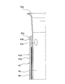
- FIG. 1A is an overall perspective view of the flavor aspirator according to the embodiment.
- FIG. 1B is an overall perspective view of a flavor aspirator according to an embodiment in which a flavor generating article is held.
- the flavor aspirator 10 according to the present embodiment is configured to generate an aerosol containing an aerosol by heating, for example, a flavor generating article 110 having a flavor source containing an aerosol source.
- the flavor aspirator 10 includes a top housing 11A, a bottom housing 11B, a cover 12, a switch 13, a lid 14, a first vent 15, a cap 16, and the like.
- the top housing 11A and the bottom housing 11B are connected to each other to form the outermost outer housing 11 of the flavor aspirator 10.
- the outer housing 11 is sized to fit in the user's hand. When the user uses the flavor aspirator 10, the flavor aspirator 10 can be held by hand to suck the flavor.
- the top housing 11A has an opening (not shown), and the cover 12 is coupled to the top housing 11A so as to close the opening.
- the cover 12 has an opening 12a into which the flavor generating article 110 can be inserted.
- the lid portion 14 is configured to open and close the opening 12a of the cover 12.
- the lid portion 14 is attached to the cover 12 and is configured to be movable along the surface of the cover 12 between the first position for closing the opening 12a and the second position for opening the opening 12a.
- the cover Thereby, the lid portion 14 can allow or restrict the access of the flavor generating article 110 to the inside of the flavor aspirator 10 (the opening 60b of the insertion guide member 60 shown in FIG. 4).
- the switch 13 is used to switch the operation of the flavor aspirator 10 on and off. For example, by operating the switch 13 with the flavor generating article 110 inserted in the opening 12a as shown in FIG. 1B, power is supplied to a heating member (not shown) from a power source (not shown), and the flavor generating article 110 is supplied. Can be heated without burning. When the flavor generating article 110 is heated, the aerosol evaporates from the aerosol source contained in the flavor generating article 110, and the flavor of the flavor source is incorporated into the aerosol. The user can suck the aerosol containing the flavor by sucking the portion (the portion shown in FIG. 1B) protruding from the flavor suction device 10 of the flavor generating article 110.
- the first vent 15 is a vent for introducing air into the heating assembly 41 (see FIG. 3) housed in the internal space of the outer housing 11.
- the cap 16 is detachably configured on the bottom housing 11B. By attaching the cap 16 to the bottom housing 11B, a first vent 15 is formed between the bottom housing 11B and the cap 16.
- the cap 16 may have, for example, a through hole or notch (not shown).
- the longitudinal direction of the flavor aspirator 10 means the direction in which the flavor generating article 110 is inserted into the opening 12a.
- the side where a fluid such as air flows in is the upstream side
- the side where the fluid flows out is the downstream side.
- FIG. 2 is a cross-sectional view of the flavor generating article 110.
- the flavor generating article 110 has a base material portion 110A including a filling material 111 and a first wrapping paper 112 for winding the filling material 111, and a side opposite to the base material portion 110A. It has a mouthpiece 110B, which forms an end portion of the.
- the base material portion 110A and the mouthpiece portion 110B are connected by a second wrapping paper 113 different from the first wrapping paper 112. However, the second wrapping paper 113 may be omitted, and the base material portion 110A and the mouthpiece portion 110B may be connected by using the first wrapping paper 112.
- the mouthpiece 110B in FIG. 2 has a paper tube portion 114, a filter portion 115, and a hollow segment portion 116 arranged between the paper tube portion 114 and the filter portion 115.
- the hollow segment portion 116 is composed of, for example, a packing layer having one or a plurality of hollow channels and a plug wrapper covering the filling layer. Since the packed bed has a high fiber filling density, air and aerosols flow only through the hollow channels during suction, and hardly flow inside the packed bed. In the flavor generating article 110, when it is desired to reduce the decrease due to the filtration of the aerosol component in the filter portion 115, shortening the length of the filter portion 115 and replacing it with the hollow segment portion 116 increases the delivery amount of the aerosol. It is effective for.
- the mouthpiece 110B in FIG. 2 is composed of three segments, but in the present embodiment, the mouthpiece 110B may be composed of one or two segments, or four or more. It may be composed of segments.
- the hollow segment portion 116 may be omitted, and the paper tube portion 114 and the filter portion 115 may be arranged adjacent to each other to form the mouthpiece portion 110B.
- the length of the flavor generating article 110 in the longitudinal direction is preferably 40 mm to 90 mm, more preferably 50 mm to 75 mm, and even more preferably 50 mm to 60 mm.
- the circumference of the flavor generating article 110 is preferably 15 mm to 25 mm, more preferably 17 mm to 24 mm, and even more preferably 20 mm to 23 mm.
- the length of the base material portion 110A in the flavor generating article 110 may be 20 mm
- the length of the first wrapping paper 112 may be 20 mm
- the length of the hollow segment portion 116 may be 8 mm
- the length of the filter portion 115 may be 7 mm.
- the length of these individual segments can be appropriately changed according to manufacturing suitability, required quality, and the like.
- the filler 111 of the flavor generating article 110 may contain an aerosol source that is heated at a predetermined temperature to generate an aerosol.
- the type of aerosol source is not particularly limited, and extracts from various natural products and / or their constituents can be selected depending on the application. Aerosol sources include, for example, glycerin, propylene glycol, triacetin, 1,3-butanediol, and mixtures thereof.
- the content of the aerosol source in the filler 111 is not particularly limited, and is usually 5% by weight or more, preferably 10% by weight or more, from the viewpoint of sufficiently generating an aerosol and imparting a good flavor and taste. Yes, and usually 50% by weight or less, preferably 20% by weight or less.
- the filling 111 of the flavor generating article 110 in the present embodiment may contain tobacco chopped as a flavor source.
- the material for chopping tobacco is not particularly limited, and known materials such as lamina and middle bone can be used.
- the range of the content of the filling material 111 in the flavor generating article 110 is, for example, 200 mg to 400 mg, preferably 250 mg to 320 mg in the case of a circumference of 22 mm and a length of 20 mm.
- the water content of the packing 111 is, for example, 8% by weight to 18% by weight, preferably 10% by weight to 16% by weight. With such a water content, the occurrence of winding stains is suppressed, and the hoisting suitability of the base material portion 110A during production is improved.
- the size of the tobacco chopped used as the filling material 111 or the preparation method thereof there are no particular restrictions on the size of the tobacco chopped used as the filling material 111 or the preparation method thereof.
- dried tobacco leaves may be chopped to a width of 0.8 mm to 1.2 mm.
- dried tobacco leaves may be crushed and homogenized so that the average particle size is about 20 ⁇ m to 200 ⁇ m, processed into a sheet, and chopped into a width of 0.8 mm to 1.2 mm. ..
- the sheet processed product which has been gathered without being carved may be used as the filling material 111.
- the filling material 111 may contain one kind or two or more kinds of fragrances.
- the type of the flavor is not particularly limited, but menthol is preferable from the viewpoint of imparting a good taste.
- the first wrapping paper 112 and the second wrapping paper 113 of the flavor generating article 110 can be made from a base paper having a basis weight of, for example, 20 gsm to 65 gsm, preferably 25 gsm to 45 gsm.
- the thickness of the first wrapping paper 112 and the second wrapping paper 113 is not particularly limited, but is 10 ⁇ m to 100 ⁇ m, preferably 20 ⁇ m to 75 ⁇ m from the viewpoint of rigidity, breathability, and ease of adjustment during papermaking. , More preferably 30 ⁇ m to 50 ⁇ m.
- the first wrapping paper 112 and the second wrapping paper 113 of the flavor generating article 110 may contain a filler.
- the content of the filler may be 10% by weight to 60% by weight, preferably 15% by weight to 45% by weight, based on the total weight of the first rolling paper 112 and the second rolling paper 113.
- the filler is preferably 15% by weight to 45% by weight with respect to a preferable range of basis weight (25 gsm to 45 gsm).
- the filler for example, calcium carbonate, titanium dioxide, kaolin and the like can be used.
- the paper containing such a filler exhibits a preferable white-based bright color from the viewpoint of appearance used as a rolling paper for the flavor-generating article 110, and can permanently maintain whiteness.
- the ISO whiteness of the wrapping paper can be increased to 83% or more.
- the first wrapping paper 112 and the second wrapping paper 113 preferably have a tensile strength of 8N / 15 mm or more.
- This tensile strength can be increased by reducing the content of the filler.
- the tensile strength can be increased by reducing the content of the filler from the upper limit of the content of the filler shown in the range of each basis weight illustrated above.
- FIG. 3 is a cross-sectional view taken along the line 3-3 shown in FIG. 1A.
- the flavor aspirator 10 has a power supply unit 20, a circuit unit 30, and a heating unit 40 in the internal spaces of the outer housing 11 and the inner housing 17.
- the top housing 11A and the bottom housing 11B constituting the outer housing 11 surround the inner housing 17 and store the inner housing 17 in the internal space.
- the circuit unit 30 includes a first circuit board 31, a second circuit board 32, and a third circuit board 33, which are electrically connected to each other.
- the first circuit board 31 is arranged so as to extend in the longitudinal direction adjacent to one surface of the rectangular power supply 21 as shown in the figure, for example.
- a partition wall 34 is provided between the first circuit board 31 and the heating unit 40, whereby at least a part of the area accommodating the power supply unit 20 and the first circuit board 31 is partitioned.
- the partition wall 34 may be provided with a notch, a through hole, or the like for fluid communication between the space on the power supply unit 20 side and the space on the heating unit 40 side.
- the second circuit board 32 is arranged inside the top housing 11A between the cover 12 and the power supply unit 20, and extends in a direction orthogonal to the extending direction of the first circuit board 31.
- the switch 13 is arranged adjacent to the second circuit board 32. When the user presses the switch 13, a part of the switch 13 may come into contact with the second circuit board 32.
- the third circuit board 33 is arranged so as to extend in the longitudinal direction in a space formed on the opposite side of the opening 12a (see FIG. 1B) with respect to the heating portion 40.
- the third circuit board 33 has a main surface on which various electronic components are mounted.
- the third circuit board 33 may be arranged in the bottom housing 11B so that its main surface is inclined with respect to the longitudinal direction. As a result, the main surface of the third circuit board 33 can be enlarged, and the space inside the bottom housing 11B can be effectively utilized.
- the first circuit board 31, the second circuit board 32, and the third circuit board 33 include, for example, a microprocessor and the like, and can control the supply of electric power from the power supply unit 20 to the heating unit 40.
- the first circuit board 31, the second circuit board 32, and the third circuit board 33 can control the heating of the flavor-generating article 110 by the heating unit 40.
- the power supply unit 20 has a power supply 21 that is electrically connected to the first circuit board 31, the second circuit board 32, and the third circuit board 33.
- the power source 21 can be, for example, a rechargeable battery or a non-rechargeable battery.
- the power supply 21 is electrically connected to the heating unit 40 via at least one of the first circuit board 31, the second circuit board 32, and the third circuit board 33.
- the power source 21 can supply electric power to the heating unit 40 so as to appropriately heat the flavor generating article 110.
- the power supply 21 is arranged in parallel with the heating unit 40. As a result, even if the size of the power supply 21 is increased, it is possible to prevent the length of the flavor aspirator 10 from becoming longer in the longitudinal direction.
- the flavor aspirator 10 has a terminal 22 that can be connected to an external power source.
- the terminal 22 can be connected to a cable such as a micro USB.
- the power supply 21 is a rechargeable battery
- a current can flow from the external power supply to the power supply 21 to charge the power supply 21.
- a data transmission cable such as a micro USB
- the heating unit 40 has a heating assembly 41 extending in the longitudinal direction, an inlet tube 50 having an L-shaped cross section, and an insertion guide member 60 having a substantially tubular shape.
- the heating assembly 41 includes a plurality of tubular members, and forms a tubular body as a whole.
- the heating assembly 41 is configured to accommodate a part of the flavor generating article 110 inside, and has a function of defining a flow path of air supplied to the flavor generating article 110 and a function of heating the flavor generating article 110 from the outer circumference. Have.
- the bottom housing 11B is formed with a first vent 15 and a second vent 18 for introducing air into the heating assembly 41.
- the first vent 15 communicates fluid with the upstream end of the flow path that penetrates the inlet pipe 50 and reaches the heating assembly 41. That is, the first vent 15 communicates fluidly with the upstream end of the heating assembly 41 via the through flow path of the inlet pipe 50.
- the second vent 18 communicates fluidly with the upstream end of the air flow path 18A formed between the outer housing 11 and the inner housing 17. Further, since the downstream end of the air flow path 18A is in fluid communication with the upstream end of the flow path penetrating the inlet pipe 50, the second vent 18 is finally connected to the heating assembly 41 as well as the first vent 15. Fluid communication.
- the downstream end of the heating assembly 41 penetrates the insertion guide member 60 and communicates fluidly with the upstream end of the flow path leading to the opening 12a shown in FIG. 1B.
- the flavor generating article 110 When the flavor generating article 110 is inserted into the inside of the flavor aspirator 10 through the opening 12a of the cover 12 as shown in FIG. 1B, the flavor generating article 110 passes through the insertion guide member 60, and a part of the flavor generating article 110 is part of the heating assembly 41. Placed inside. Therefore, it is preferable that the insertion guide member 60 is formed so that the inner diameter on the cover 12 side is gradually larger than the inner diameter on the downstream side of the heating assembly 41. As a result, the flavor generating article 110 can be easily inserted into the insertion guide member 60 through the opening 12a.
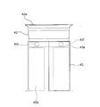
- FIG. 4 is a cross-sectional view of the heating unit 40.
- the heating unit 40 includes a heating assembly 41, an inlet tube 50, and an insertion guide member 60.
- the heating assembly 41 includes a cup-shaped container (heat conductive member) 42 forming a chamber capable of accommodating the flavor generating article 110, a heating member 43 configured to heat the flavor generating article 110, and a heat shrink tube (heat shrink tube). It has a fixing member) 44 and a heat insulating portion 45.
- the container 42 has a first opening 42a for inserting the flavor generating article 110 at one end and a second opening 42b at the other end capable of supplying air toward the flavor generating article 110 to generate the flavor. It is configured to accommodate the article 110.
- the container 42 has a second surface configured to face the flavor generating article 110 when the flavor generating article 110 is attached to the heating member 43.
- the container 42 surrounds the outer peripheral surface of the flavor generating article 110 inserted from the first opening 42a, and is configured to come into contact with at least a part of the outer peripheral surface of the flavor generating article 110 (the first inner peripheral surface). It has two sides).
- the inner diameter of the container 42 gradually increases from the second opening 42b side toward the first opening 42a, that is, from the opposite side of the first opening 42a toward the first opening 42a. It is getting bigger. This makes it easier to insert the flavor generating article 110 into the container 42 through the first opening 42a.
- the container 42 has a bottom wall 42d against which the tip of the flavor generating article 110 inserted from the first opening 42a is abutted.
- the second opening 42b is a through hole formed in the bottom wall 42d of the container 42.
- the second opening 42b is located on the upstream side of the air flow, and the first opening 42a is located on the downstream side.
- a boss (projection) 42c configured to press and hold the outer peripheral surface of the inserted flavor generating article 110 inward in the radial direction is formed on the inner peripheral surface of the container 42.
- the heating member 43 may be a flexible polyimide heater composed of, for example, two films (bases) such as PI (polyimide) sandwiching a heating element (heating element) such as stainless steel.
- the heating member 43 is arranged so as to come into contact with the container 42.
- the heating member 43 is arranged on the outer peripheral surface (first surface) of the container 42, and the inner surface of the heating member 43 is in close contact with the outer surface of the container 42. Since the heating member 43 is arranged along the outer peripheral surface of the container 42, it is deformed into a substantially tubular shape as a whole.
- the heating member 43 generates heat applied to the flavor generating article 110.
- the container 42 is formed of a metal material having high thermal conductivity such as SUS. Therefore, the heat generated by the heating member 43 is transferred to the entire container 42, and as a result, the flavor-generating article 110 inserted in the container 42 is heated.
- the heat-shrinkable tube 44 has a tubular shape, and the heating member 43 maintains a state of being in close contact with the container 42. Specifically, the heat-shrinkable tube 44 is heat-shrinked by applying heat while being arranged on the outer peripheral side of the heating member 43, whereby the heating member 43 is pressed against the container 42. Stress 43.
- the heat-shrinkable tube 44 covers a part of the downstream side of the inlet pipe 50 and is heat-shrinked, so that the container 42 and the inlet pipe 50 can be brought into close contact with each other.
- the heat insulating portion 45 is a tubular member having a double-tube structure, and is arranged at a predetermined interval outward in the radial direction (direction orthogonal to the longitudinal direction) from the heat-shrinkable tube 44. Further, the heat insulating portion 45 is formed of a metal material such as SUS like the container 42.
- the heat insulating portion 45 has an inner tubular member 45a, an outer tubular member 45b, a first annular member 45c, and a second annular member 45d.
- the inner tubular member 45a and the outer tubular member 45b are arranged side by side in the radial direction of the inserted flavor generating article 110.
- the first annular member 45c is arranged on the downstream side of the inner tubular member 45a and the outer tubular member 45b
- the second annular member 45d is arranged on the upstream side of the inner tubular member 45a and the outer tubular member 45b
- the heat insulating portion 45 may be a vacuum heat insulating material having decompressed air or vacuum inside the double tube structure. Specifically, by depressurizing the space formed by the inner tubular member 45a and the outer tubular member 45b and the first annular member 45c and the second annular member 45d, the heat generated from the heating member 43 is generated by the heating assembly. It becomes difficult to be transmitted to the outside of 41.
- the inlet pipe 50 is formed of, for example, a resin material, and fluid communicates with the container 42 through the second opening 42b to introduce air into the container 42.
- the inlet pipe 50 is a member forming a pipe having a downstream end 50a that engages with the upstream end (end on the second opening 42b side) of the container 42 and an upstream end 50b on the opposite side of the downstream end 50a. ..
- the inlet pipe 50 forms an internal flow path for introducing air toward the second opening 42b of the container 42.
- the inlet tube 50 shown in FIG. 4 forms an internal flow path curved in an L shape. Further, the upstream end 50b of the inlet pipe 50 is arranged close to or adjacent to the first vent 15 and the air flow path 18A shown in FIG.
- the insertion guide member 60 is formed of, for example, a resin material, and fluidly communicates with the container 42 through the first opening 42a.
- the insertion guide member 60 is provided between the cover 12 having the opening 12a (see FIG. 1B) and the downstream end of the heating assembly 41 to guide the insertion of the flavor generating article 110 into the container 42.
- the insertion guide member 60 is a member having an upstream end 60a that engages with the downstream end (end on the first opening 42a side) of the container 42 and an opening 60b on the opposite side of the upstream end 60a.
- the upstream end 60a (end on the first opening 42a side) of the insertion guide member 60 surrounds the outer circumference of the downstream end of the container 42, and a predetermined gap is provided between the insertion guide member 60 and the container 42. There is. That is, the upstream end of the insertion guide member 60 has an inner diameter larger than the outer diameter of the downstream end of the container 42, which can accommodate the downstream end of the container 42.
- the opening 60b communicates with the opening 12a of the cover 12 (see FIG. 1B) so that the flavor generating article 110 can be inserted.
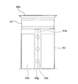
- FIG. 5 is a developed view of the heating member 43 arranged along the outer peripheral surface of the container 42.
- the heating member 43 includes a heat generating resistor 43a that generates heat, an insulating polyimide film 43b that supports the heat generating resistor 43a by sandwiching it between two films, and a power supply 21 (FIG. 5). It has a wiring portion 43c that is electrically connected to (see 3).
- three systems of heat generating resistors 43a are provided.
- the heat generation resistor 43a and the polyimide film 43b form a heat generation region 43d in which the heat generation resistor 43a is arranged and a non-heat generation region 43e adjacent to the heat generation region 43d in which the heat generation resistor 43a is not arranged.
- FIG. 6 is an enlarged cross-sectional view of the container 42, the heating member 43, and the heat shrink tube 44.
- the heating member 43 is arranged on the outer peripheral surface of the container 42.
- a non-heating region 43e in which the heat generating resistor 43a is not arranged extends from the heat generating region 43d in which the heat generating resistor 43a is arranged toward the first opening 42a side.
- the heat shrink tube 44 is arranged so as to surround the outer circumference of the heating member 43.
- the boss 42c is provided on the inner peripheral surface of the container 42 in a region corresponding to the non-heating region 43e of the heating member 43 arranged on the outer peripheral surface of the container 42. That is, the boss 42c is provided at a position separated from the heat generating region 43d of the heating member 43. Further, the boss 42c may be formed by embossing or may be formed by a convex member attached to the inner peripheral surface of the container 42 as long as it has a spherical surface. Further, the boss 42c may be made of metal or non-metal.
- the end portion of the heat-shrinkable tube 44 on the first opening 42a side is arranged so as to extend toward the first opening 42a side from the boss 42c.
- the end portion of the heat insulating portion 45 (see FIG. 4) on the first opening 42a side is arranged so as to extend toward the first opening 42a side from the boss 42c in the longitudinal direction.
- the flavor generating article 110 can be uniformly heated. ..
- a boss is formed on the inner peripheral surface of the container 42 corresponding to the heat generation region 43d of the heating member 43 by embossing, a gap is formed on the back surface of the boss, so that the heat is not transferred to the flavor generating article 110. Become uniform.
- the container 42 becomes thicker by the amount of the boss, and the inner peripheral surface of the container 42 becomes thicker. Is far from the heating member 43, so that the heat is transferred to the flavor generating article 110 in a non-uniform manner. Therefore, by forming the boss 42c while avoiding the heat generating region 43d, the flavor generating article 110 can be uniformly heated.
- the boss 42c on the inner peripheral surface of the container 42 in a region corresponding to the non-heat generating region 43e of the heating member 43 arranged on the outer peripheral surface of the container 42, damage to the flavor generating article 110 is suppressed.
- the flavor generating article 110 inserted in the container 42 can be grasped.
- a boss is formed in the vicinity of the first opening 42a of the flavor generating article 110, a wide range in the longitudinal direction of the flavor generating article 110 comes into frictional contact with the boss during the insertion operation of the flavor generating article 110, so that the flavor generating article 110 The outer surface is easily damaged.
- the boss 42c in the region corresponding to the non-heat generating region 43e, the range in which the flavor generating article 110 is in frictional contact with the boss 42c is narrowed, and damage to the flavor generating article 110 is suppressed while being placed in the container 42.
- the inserted flavor generating article 110 can be grasped.
- the boss 42c is made of metal, the metal is resistant to friction, so that the ability to grip the flavor-generating article 110 is reduced even when the flavor-generating article 110 is repeatedly inserted and removed. Can be prevented.
- FIG. 7 is an enlarged view of the container 42 and the heating member 43.
- the heating member 43 is a sheet wound over the entire circumference of the outer circumference of the container 42, and the side ends of the sheet in the circumferential direction are butted against each other (in FIG. 7, the center of the heating member 43). See the vertical line in).
- a first band-shaped region 43f extending along the circumferential direction of the outer peripheral surface of the container 42 is formed.
- the first band-shaped region 43f is formed at the end of the heating member 43 on the side of the first opening 42a of the container 42.
- the boss 42c is provided on the inner peripheral surface of the container 42 in a region corresponding to the first band-shaped region 43f of the heating member 43 arranged on the outer peripheral surface of the container 42.
- a plurality of bosses 42c may be provided along the extending direction of the first band-shaped region 43f.
- the flavor generating article 110 inserted in the container 42 is provided. It can be gripped stably.
- a boss is formed on the side of the second opening 42b (see FIG. 4) of the container 42, the portion near the tip of the flavor generating article 110 is gripped, and the flavor generating article 110 swings with the boss as a fulcrum. is there. Therefore, by forming the boss 42c in the region corresponding to the first band-shaped region 43f, the flavor generating article 110 can be stably gripped. Further, by providing a plurality of bosses 42c, the flavor generating article 110 can be gripped more stably.
- FIG. 8 is another enlarged view of the container and the heating member.
- the heating member 43 is a sheet wound over the entire circumference of the outer circumference of the container 42, and the side ends of the sheet in the circumferential direction are butted against each other (in FIG. 8, the center of the heating member 43). See the vertical line in).
- the side ends of the sheet in the circumferential direction may at least partially overlap each other.
- a second band-shaped region 43g extending along the longitudinal direction of the container 42 is formed in the non-heating region 43e of the heating member 43. That is, the second band-shaped region 43g is formed at both end portions of the sheet in the radial direction. Further, the second band-shaped region 43g may be formed in a region where the side ends of the sheet overlap at least partially.
- the boss 42c is provided on the inner peripheral surface of the container 42 in a region corresponding to the second band-shaped region 43g of the heating member 43 arranged on the outer peripheral surface of the container 42. The boss 42c may be provided within the range of the heat generating region 43d with respect to the extending direction of the second band-shaped region 43g.
- bosses 42c may be provided along the extending direction of the second band-shaped region 43g. Further, the boss 42c may be provided in the region corresponding to the first belt-shaped region 43f shown in FIG. 7 in addition to the region corresponding to the second belt-shaped region 43g.
- the boss 42c is a region corresponding to the second band-shaped region 43g of the heating member 43 arranged on the outer peripheral surface of the container 42 on the inner peripheral surface of the container 42, and the extending direction of the second band-shaped region 43g.
- the heating member includes a heating member which is a heating assembly and is configured to heat the flavor-generating article, and a heat conductive member which transfers the heat generated by the heating member to the flavor-generating article.
- a heating element that generates heat and an insulating substrate that supports the heating element, and the heating element and the substrate are adjacent to a heating element in which the heating element is arranged and a heating element.
- a non-heating region is formed in which the heating member is not arranged, and the heat conductive member faces the first surface on which the heating member is arranged and the flavor generating article when the flavor generating article is attached to the heating member.
- the configured second surface and the protrusions on the second surface which are provided in the area corresponding to the non-heating area of the heating member arranged on the first surface and which press and hold the attached flavor generating article. Have.
- the heat conductive member forms a chamber capable of accommodating the flavor generating article, and the outer peripheral surface and the inner peripheral surface of the chamber are the first surface and the heat conductive member. Each second surface is formed.
- the non-heating region has a first band-shaped region extending along the circumferential direction of the outer peripheral surface, and the protrusion is the first band-shaped region of the inner peripheral surface. It is provided in the area corresponding to the area.
- a plurality of protrusions are provided along the extending direction of the first band-shaped region.
- the chamber has a first opening for inserting a flavor generating article, and the first band-shaped region is a heat conductive member in the heating member. It is formed at the end on the first opening side of the.
- a fixing member for fixing the heating member to the heat conductive member is further provided so as to surround the outer periphery of the heating member and fixed in the longitudinal direction of the attached flavor generating article.
- the end portion of the member on the first opening side of the heat conductive member is arranged on the first opening side of the heat conductive member rather than the protrusion.
- the heat insulating portion arranged apart from the heating member in the direction orthogonal to the longitudinal direction of the attached flavor generating article is further provided, and the longitudinal direction is provided.
- the end portion of the heat insulating portion on the first opening side of the heat conductive member is arranged on the first opening side of the heat conductive member rather than the protrusion.
- the inner diameter of the heat conductive member gradually increases from the opposite side of the first opening toward the first opening. Has a part.
- the heat conductive member is an insertion guide that guides the insertion of the flavor generating article into the heat conductive member through the first opening. Fluid communication with the member.
- the inner diameter of the insertion guide member gradually increases as the distance from the first opening increases.
- the chamber has a second opening capable of supplying air towards the flavoring article.
- the non-heating region has a second band-shaped region extending along the longitudinal direction of the attached flavor-generating article.
- the protrusions are provided on the second surface in a region corresponding to the second band-shaped region.
- the protrusion is provided within the range of the heat generating region in the extending direction of the second band-shaped region.
- a plurality of protrusions are provided along the extending direction of the second band-shaped region.
- the heating member is a sheet wound around the outer periphery of the heat conductive member, and the second band-shaped region is the attached flavor. It is formed at both end portions of the sheet in a direction orthogonal to the longitudinal direction of the generated article.
- the second band-shaped region is a region where the side ends of the sheet overlap at least partially.
- the heating element is sandwiched between a pair of substrates.
- a flavor aspirator including any heating assembly from the first form to the seventeenth form is provided.
Landscapes
- Packages (AREA)
- Disinfection, Sterilisation Or Deodorisation Of Air (AREA)
- Cookers (AREA)
Abstract
新たな構造を有する香味吸引器および挿入ガイド部材を提供する。加熱アセンブリが提供される。この加熱アセンブリは、香味発生物品を加熱するように構成された加熱部材(43)と、加熱部材で発生した熱を香味発生物品に伝える熱伝導部材(42)と、を備える。加熱部材は、熱を発生する発熱体(43a)と、発熱体を支持する絶縁性の基体(43b)と、を有し、発熱体と基体とにより、発熱体が配置された発熱領域(43d)と、発熱領域に隣接し、発熱体が配置されていない非発熱領域(43e)とが形成される。熱伝導部材は、加熱部材が配置される第1面と、香味発生物品が前記加熱部材に装着されたときに、前記香味発生物品に対向するように構成された第2面と、第2面の、第1面に配置された加熱部材の非発熱領域に対応する領域に設けられ、装着された香味発生物品を押圧して保持する突起と、を有する。
Description
本発明は、加熱アセンブリおよび香味吸引器に関する。
従来、香味源を含有する基材の燃焼をすることなく香味を吸引するための香味吸引器が知られている。このような香味吸引器として、たばこレシーバ中に挿入されたたばこを摺動的に受ける加熱要素を備えた電気喫煙システムが知られている(例えば、特許文献1参照)。
本発明の目的は、新たな構造を有する加熱アセンブリおよび香味吸引器を提供することである。
本発明の一実施形態によれば、加熱アセンブリが提供される。この加熱アセンブリは、香味発生物品を加熱するように構成された加熱部材と、加熱部材で発生した熱を香味発生物品に伝える熱伝導部材と、を備える。加熱部材は、熱を発生する発熱体と、発熱体を支持する絶縁性の基体と、を有し、発熱体と基体とにより、発熱体が配置された発熱領域と、発熱領域に隣接し、発熱体が配置されていない非発熱領域とが形成される。熱伝導部材は、加熱部材が配置される第1面と、香味発生物品が加熱部材に装着されたときに香味発生物品に対向するように構成された第2面と、第2面の、第1面に配置された加熱部材の非発熱領域に対応する領域に設けられ、装着された香味発生物品を押圧して保持する突起と、を有する。
本発明の他の一実施形態によれば、上記加熱アセンブリを備えた香味吸引器が提供される。
以下、本発明の実施形態について図面を参照して説明する。以下で説明する図面において、同一のまたは相当する構成要素には、同一の符号を付して重複した説明を省略する。
図1Aは、一実施形態に係る香味吸引器の全体斜視図である。図1Bは、香味発生物品を保持した状態の一実施形態に係る香味吸引器の全体斜視図である。本実施形態に係る香味吸引器10は、例えば、エアロゾル源を含んだ香味源を有する香味発生物品110を加熱することで、香味を含むエアロゾルを生成するように構成される。
図1Aおよび図1Bに示すように、香味吸引器10は、トップハウジング11Aと、ボトムハウジング11Bと、カバー12と、スイッチ13と、蓋部14と、第1通気口15と、キャップ16と、を有する。トップハウジング11Aとボトムハウジング11Bとは、互いに接続されることで、香味吸引器10の最外のアウタハウジング11を構成する。アウタハウジング11は、使用者の手に収まるようなサイズである。使用者が香味吸引器10を使用する際は、香味吸引器10を手で保持して、香味を吸引することができる。
トップハウジング11Aは、図示しない開口を有し、カバー12は、当該開口を閉じるようにトップハウジング11Aに結合される。図1Bに示すように、カバー12は、香味発生物品110を挿入可能な開口12aを有する。蓋部14は、カバー12の開口12aを開閉するように構成される。具体的には、蓋部14は、カバー12に取り付けられ、開口12aを閉鎖する第1位置と開口12aを開放する第2位置との間を、カバー12の表面に沿って移動可能に構成される。これにより、蓋部14は、香味吸引器10の内部(図4に示す挿入ガイド部材60の開口60b)への香味発生物品110のアクセスを許可または制限することができる。
スイッチ13は、香味吸引器10の作動のオンとオフとを切り替えるために使用される。例えば、使用者は、図1Bに示すように香味発生物品110を開口12aに挿入した状態でスイッチ13を操作することで、図示しない加熱部材に図示しない電源から電力が供給され、香味発生物品110を燃焼させずに加熱することができる。香味発生物品110が加熱されると、香味発生物品110に含まれるエアロゾル源からエアロゾルが蒸発し、エアロゾルに香味源の香味が取り込まれる。使用者は、香味発生物品110の香味吸引器10から突出した部分(図1Bにおいて図示された部分)を吸引することで、香味を含んだエアロゾルを吸引することができる。
第1通気口15は、アウタハウジング11の内部空間に格納される加熱アセンブリ41(図3参照)の内部に空気を導入するための通気口である。キャップ16は、ボトムハウジング11Bに着脱自在に構成されている。キャップ16がボトムハウジング11Bに取り付けられることで、ボトムハウジング11Bとキャップ16との間に第1通気口15が形成される。キャップ16は、例えば図示しない貫通孔または切欠き等を有し得る。なお、本明細書において、香味吸引器10の長手方向とは、香味発生物品110が開口12aに挿入される方向をいう。また、本明細書の香味吸引器10において、空気等の流体が流入する側(例えば、第1通気口15側)を上流側とし、流体が流出する側(例えば開口12a側)を下流側とする。
次に、本実施形態に係る香味吸引器10に使用される香味発生物品110の構成について説明する。図2は、香味発生物品110の断面図である。図2に示す実施形態においては、香味発生物品110は、充填物111と、充填物111を巻装する第1の巻紙112と、を含む基材部110Aと、基材部110Aとは反対側の端部を形成する吸口部110Bと、を有する。基材部110Aと吸口部110Bとは、第1の巻紙112とは異なる第2の巻紙113によって連結されている。ただし、第2の巻紙113を省略し、第1の巻紙112を用いて基材部110Aと吸口部110Bとを連結することもできる。
図2中の吸口部110Bは、紙管部114と、フィルタ部115と、紙管部114とフィルタ部115との間に配置された中空セグメント部116と、を有する。中空セグメント部116は、例えば、1つまたは複数の中空チャネルを有する充填層と、充填層を覆うプラグラッパーとで構成される。充填層は、繊維の充填密度が高いため、吸引時、空気やエアロゾルは、中空チャンネルのみを流れることになり、充填層内はほとんど流れない。香味発生物品110において、フィルタ部115でのエアロゾル成分の濾過による減少を少なくしたいときに、フィルタ部115の長さを短くして中空セグメント部116で置き換えることは、エアロゾルのデリバリ量を増大させるために有効である。
図2中の吸口部110Bは、3つのセグメントから構成されているが、本実施形態において、吸口部110Bは、1つまたは2つのセグメントから構成されていてもよいし、4つまたはそれ以上のセグメントから構成されていてもよい。例えば、中空セグメント部116を省略し、紙管部114とフィルタ部115とを互いに隣接配置して吸口部110Bを形成することもできる。
図2に示す実施形態において、香味発生物品110の長手方向の長さは、40mm~90mmであることが好ましく、50mm~75mmであることがより好ましく、50mm~60mmであることがさらに好ましい。香味発生物品110の円周は、15mm~25mmであることが好ましく、17mm~24mmであることがより好ましく、20mm~23mmであることがさらに好ましい。また、香味発生物品110における基材部110Aの長さは20mm、第1の巻紙112の長さは20mm、中空セグメント部116の長さは8mm、フィルタ部115の長さは7mmであってよいが、これら個々のセグメントの長さは、製造適性、要求品質等に応じて、適宜変更できる。
本実施形態において、香味発生物品110の充填物111は、所定温度で加熱されてエアロゾルを発生するエアロゾル源を含有し得る。エアロゾル源の種類は、特に限定されず、用途に応じて種々の天然物からの抽出物質および/またはそれらの構成成分を選択することができる。エアロゾル源として、例えば、グリセリン、プロピレングリコール、トリアセチン、1,3-ブタンジオール、およびこれらの混合物を挙げることができる。充填物111中のエアロゾル源の含有量は、特に限定されず、十分にエアロゾルを発生するとともに、良好な香喫味の付与の観点から、通常5重量%以上であり、好ましくは10重量%以上であり、また、通常50重量%以下であり、好ましくは20重量%以下である。
本実施形態における香味発生物品110の充填物111は、香味源としてたばこ刻みを含有し得る。たばこ刻みの材料は特に限定されず、ラミナや中骨等の公知のものを用いることができる。香味発生物品110における充填物111の含有量の範囲は、円周22mm、長さ20mmの場合、例えば、200mg~400mgであり、250mg~320mgであることが好ましい。充填物111の水分含有量は、例えば、8重量%~18重量%であり、10重量%~16重量%であることが好ましい。このような水分含有量であると、巻染みの発生を抑制し、基材部110Aの製造時の巻上適性を良好にする。
充填物111として用いるたばこ刻みの大きさやその調製法については特に制限はない。例えば、乾燥したたばこ葉を、幅0.8mm~1.2mmに刻んだものを用いてもよい。また、乾燥したたばこ葉を平均粒径が20μm~200μm程度になるように粉砕して均一化したものをシート加工し、それを幅0.8mm~1.2mmに刻んだものを用いてもよい。さらに、上記のシート加工したものについて刻まずにギャザー加工したものを充填物111として用いてもよい。また、充填物111は、1種または2種以上の香料を含んでいてもよい。当該香料の種類は特に限定されないが、良好な喫味の付与の観点から、好ましくはメンソールである。
本実施形態において、香味発生物品110の第1の巻紙112および第2の巻紙113は、坪量が例えば20gsm~65gsmであり、好ましくは25gsm~45gsmである原紙から作られることができる。第1の巻紙112および第2の巻紙113の厚みは、特に限定されないが、剛性、通気性、および製紙時の調整の容易性の観点から、10μm~100μmであり、好ましくは20μm~75μmであり、より好ましくは30μm~50μmである。
本実施形態において、香味発生物品110の第1の巻紙112および第2の巻紙113には、填料が含まれ得る。填料の含有量は、第1の巻紙112および第2の巻紙113の全重量に対して10重量%~60重量%を挙げることができ、15重量%~45重量%であることが好ましい。本実施形態において、好ましい坪量の範囲(25gsm~45gsm)に対して、填料が15重量%~45重量%であることが好ましい。填料としては、例えば、炭酸カルシウム、二酸化チタン、カオリン等を使用することができる。このような填料を含む紙は、香味発生物品110の巻紙として利用する外観上の観点から好ましい白色系の明るい色を呈し、恒久的に白さを保つことができる。そのような填料を多く含有させることで、例えば、巻紙のISO白色度を83%以上にすることができる。
また、香味発生物品110の巻紙として利用する実用上の観点から、第1の巻紙112および第2の巻紙113は、8N/15mm以上の引張強度を有することが好ましい。この引張強度は、填料の含有量を少なくすることで高めることができる。具体的には、上記で例示した各坪量の範囲において示した填料の含有量の上限よりも填料の含有量を少なくすることで、引張強度を高めることができる。
次に、図1Aおよび図1Bに示した香味吸引器10の内部構造について説明する。図3は、図1Aに示した矢視3-3における断面図である。図3に示すように、香味吸引器10は、アウタハウジング11およびインナハウジング17の内部空間に、電源部20と、回路部30と、加熱部40と、を有する。アウタハウジング11を構成するトップハウジング11Aおよびボトムハウジング11Bは、インナハウジング17を取り囲んで、インナハウジング17を内部空間に格納する。
回路部30は、互いに電気的に接続された第1回路基板31と、第2回路基板32と、第3回路基板33と、を有する。第1回路基板31は、例えば、図示のように矩形状の電源21の一面に隣接して長手方向に延びて配置される。第1回路基板31と加熱部40との間には、隔壁34が設けられており、これにより、電源部20と第1回路基板31とを収容する領域の少なくとも一部が区画される。隔壁34には、電源部20側の空間と加熱部40側の空間とを流体連通する切欠きや貫通孔等が設けられてもよい。
第2回路基板32は、トップハウジング11Aの内側でカバー12と電源部20との間に配置され、第1回路基板31の延在方向と直交する方向に延びる。スイッチ13は、第2回路基板32と隣接して配置される。使用者がスイッチ13を押下したとき、スイッチ13の一部が、第2回路基板32と接触し得る。第3回路基板33は、加熱部40に対して、開口12a(図1B参照)の反対側に形成された空間において、長手方向に延びて配置される。
第3回路基板33は、種々の電子部品が取り付けられた主面を有する。例えば、第3回路基板33は、その主面が長手方向に対して傾斜するように、ボトムハウジング11B内に配置されてもよい。これにより、第3回路基板33の主面を大きくすることができ、ボトムハウジング11B内の空間を有効活用することができる。
第1回路基板31、第2回路基板32および第3回路基板33は、例えばマイクロプロセッサ等を含み、電源部20から加熱部40への電力の供給を制御することができる。これにより、第1回路基板31、第2回路基板32および第3回路基板33は、加熱部40による香味発生物品110の加熱を制御することができる。
電源部20は、第1回路基板31、第2回路基板32および第3回路基板33に電気的に接続される電源21を有する。電源21は、例えば、充電式バッテリまたは非充電式のバッテリであり得る。電源21は、第1回路基板31、第2回路基板32および第3回路基板33の少なくとも1つを介して、加熱部40と電気的に接続される。これにより、電源21は、香味発生物品110を適切に加熱するように、加熱部40に電力を供給することができる。また、図示のように、電源21は、加熱部40と並列に配置される。これにより、電源21の大きさを大きくしても、香味吸引器10の長手方向の長さが長くなることを抑制することができる。
また、香味吸引器10は、外部電源と接続可能な端子22を有する。端子22は、例えばマイクロUSB等のケーブルと接続することができる。電源21が充電式バッテリである場合は、端子22に外部電源を接続することで、外部電源から電源21に電流を流し、電源21を充電することができる。また、端子22にマイクロUSB等のデータ送信ケーブルを接続することにより、香味吸引器10の作動に関連するデータを外部装置に送信できるようにしてもよい。
加熱部40は、図示のように、長手方向に延びる加熱アセンブリ41と、断面L字状のインレット管50と、略筒状の挿入ガイド部材60と、を有する。加熱アセンブリ41は、複数の筒状の部材を含み、全体として筒状体をなしている。加熱アセンブリ41は、その内部に香味発生物品110の一部を収納可能に構成され、香味発生物品110へ供給する空気の流路を画定する機能、および香味発生物品110を外周から加熱する機能を有する。
ボトムハウジング11Bには、加熱アセンブリ41の内部に空気を導入するための第1通気口15および第2通気口18が形成される。具体的には、第1通気口15は、インレット管50を貫通して加熱アセンブリ41に至る流路の上流端と流体連通する。つまり、第1通気口15は、インレット管50の貫通流路を介して加熱アセンブリ41の上流端と流体連通する。また、第2通気口18は、アウタハウジング11とインナハウジング17との間に形成される空気流路18Aの上流端と流体連通する。さらに、空気流路18Aの下流端は、インレット管50を貫通する流路の上流端と流体連通するので、第1通気口15と同じく、第2通気口18も最終的には加熱アセンブリ41と流体連通する。
加熱アセンブリ41の下流端は、挿入ガイド部材60を貫通して図1Bに示した開口12aに至る流路の上流端と流体連通する。香味発生物品110は、図1Bに示すようにカバー12の開口12aから香味吸引器10の内部に挿入されると、挿入ガイド部材60を通過し、香味発生物品110の一部が加熱アセンブリ41の内部に配置される。このため、挿入ガイド部材60は、加熱アセンブリ41の下流側の内径の大きさよりも、カバー12側の内径の方が徐々に大きくなるように形成されることが好ましい。これにより、香味発生物品110を開口12aから挿入ガイド部材60の内部に挿入し易くなる。
図1Bに示すように、香味発生物品110が開口12aから香味吸引器10内に挿入された状態で、使用者が、香味発生物品110の香味吸引器10から突出した部分、すなわち図2に示したフィルタ部115から吸引すると、第1通気口15および第2通気口18から加熱アセンブリ41の内部に空気が流入する。流入した空気は、加熱アセンブリ41の内部を通過して、香味発生物品110から生じるエアロゾルと共に、使用者の口内に到達する。したがって、加熱アセンブリ41の第1通気口15および第2通気口18に近い側(インレット管50に近い側)は上流側であり、加熱アセンブリ41の開口12aに近い側(挿入ガイド部材60に近い側)は下流側である。
次に、図3に示した加熱部40の構成について説明する。図4は、加熱部40の断面図である。図4に示すように、加熱部40は、加熱アセンブリ41と、インレット管50と、挿入ガイド部材60と、を有する。加熱アセンブリ41は、香味発生物品110を収容可能なチャンバを形成するカップ状の容器(熱伝導部材)42と、香味発生物品110を加熱するように構成された加熱部材43と、熱収縮チューブ(固定部材)44と、断熱部45と、を有する。
容器42は、香味発生物品110を挿入するための第1開口42aを一端に有し、かつ香味発生物品110に向けて空気を供給可能な第2開口42bを他端に有して、香味発生物品110を収容可能に構成される。容器42は、香味発生物品110が加熱部材43に装着されたときに、香味発生物品110に対向するように構成された第2面を有する。本実施形態では、容器42は、第1開口42aから挿入された香味発生物品110の外周を取り囲み、香味発生物品110の外周面の少なくとも一部と接触するように構成された内周面(第2面)を有する。また、容器42は、第1開口42aの近傍において、第2開口42b側から第1開口42a側に向けて、すなわち第1開口42aの反対側から前記第1開口42aに向けて、内径が徐々に大きくなっている。これにより、香味発生物品110を第1開口42aから容器42の内部に挿入し易くなる。
さらに、容器42は、第1開口42aから挿入された香味発生物品110の先端が突き当てられるに底壁42dを有する。第2開口42bは、容器42の底壁42dに形成された貫通孔である。第2開口42bは、空気流の上流側に位置し、第1開口42aは、下流側に位置する。また、容器42の内周面には、挿入された香味発生物品110の外周面を径方向内向きに押圧して保持するように構成されたボス(突起)42cが形成されている。
加熱部材43は、例えば2枚のPI(ポリイミド)等のフィルム(基体)で、ステンレス等の発熱抵抗体(発熱体)を挟み込んで構成される、可撓性のポリイミドヒータであり得る。加熱部材43は、容器42に接触するように配置される。具体的には、図示の例では、加熱部材43が容器42の外周面(第1面)に配置され、加熱部材43の内部表面が容器42の外部表面に密着している。加熱部材43は、容器42の外周面に沿って配置されるので、全体として略筒状に変形される。
加熱部材43は、香味発生物品110に加えられる熱を発生する。容器42は、例えばSUS等の熱伝導性の高い金属材料により形成される。そのため、加熱部材43で発生した熱が容器42全体に伝達され、その結果、容器42に挿入された香味発生物品110が加熱される。
熱収縮チューブ44は、筒状であり、加熱部材43が容器42に密着した状態を維持する。具体的には、熱収縮チューブ44は、加熱部材43の外周側に配置された状態で熱が加えられることにより熱収縮しており、これにより、加熱部材43を容器42に押し付けるように加熱部材43に応力を与える。ここで、熱収縮チューブ44は、インレット管50の下流側の一部を覆って熱収縮しており、これにより、容器42とインレット管50とを密着させることができる。
断熱部45は、二重管構造を有する筒状の部材であり、熱収縮チューブ44から径方向(長手方向と直交する方向)外向きに所定の間隔を隔てて配置されている。また、断熱部45は、容器42と同様にSUS等の金属材料により形成される。断熱部45は、内側管状部材45a、外側管状部材45b、第1環状部材45cおよび第2環状部材45dを有している。内側管状部材45aおよび外側管状部材45bは、挿入された香味発生物品110の径方向に並んで配置されている。
第1環状部材45cは、内側管状部材45aおよび外側管状部材45bの下流側に配置され、第2環状部材45dは、内側管状部材45aおよび外側管状部材45bの上流側に配置されている。例えば、断熱部45は、二重管構造の内側に減圧空気または真空を有する真空断熱材であり得る。具体的には、内側管状部材45aおよび外側管状部材45bと、第1環状部材45cおよび第2環状部材45dとで形成された空間を減圧することにより、加熱部材43から発生する熱が、加熱アセンブリ41の外側に伝わりにくくなる。
インレット管50は、例えば樹脂材料により形成され、第2開口42bを介して容器42と流体連通し、容器42内に空気を導入する。インレット管50は、容器42の上流端(第2開口42b側の端部)と係合する下流端50aと、下流端50aの反対側の上流端50bと、を有する配管を形成する部材である。インレット管50は、容器42の第2開口42bに向けて空気を導入する内部流路を形成する。図4に示したインレット管50は、L字状に曲がった内部流路を形成する。また、インレット管50の上流端50bは、図3に示した第1通気口15および空気流路18Aと近接または隣接して配置される。
挿入ガイド部材60は、例えば樹脂材料により形成され、第1開口42aを介して容器42と流体連通する。挿入ガイド部材60は、開口12a(図1B参照)を有するカバー12と加熱アセンブリ41の下流端との間に設けられて、容器42への香味発生物品110の挿入を案内する。
挿入ガイド部材60は、容器42の下流端(第1開口42a側の端部)と係合する上流端60aと、上流端60aの反対側の開口60bと、を有する部材である。挿入ガイド部材60の上流端60a(第1開口42a側の端部)は、容器42の下流端の外周を取り囲み、挿入ガイド部材60と容器42との間には、所定の空隙が設けられている。すなわち、挿入ガイド部材60の上流端は、容器42の下流端を収容可能な、容器42の下流端の外径よりも大きい内径を備える。開口60bは、カバー12の開口12a(図1B参照)と流体連通し、香味発生物品110を挿入可能に構成される。
次に、図4に示した加熱部材43の構成について説明する。図5は、容器42の外周面に沿って配置された加熱部材43の展開図である。図5に示すように、加熱部材43は、熱を発生する発熱抵抗体43aと、発熱抵抗体43aを2枚のフィルムの間に挟み込んで支持する絶縁性のポリイミドフィルム43bと、電源21(図3参照)と電気的に接続される配線部43cと、を有している。本実施形態では、発熱抵抗体43aは、3系統設けられている。発熱抵抗体43aとポリイミドフィルム43bとにより、発熱抵抗体43aが配置された発熱領域43dと、発熱領域43dに隣接し、発熱抵抗体43aが配置されていない非発熱領域43eとが形成される。
次に、容器42の内周面に形成されたボス42cと加熱部材43との位置関係について詳細に説明する。図6は、容器42、加熱部材43および熱収縮チューブ44を抜粋した拡大断面図である。図6に示すように、加熱部材43は、容器42の外周面に配置されている。加熱部材43において、発熱抵抗体43aが配置された発熱領域43dから、第1開口42a側に向けて、発熱抵抗体43aが配置されていない非発熱領域43eが延在している。また、熱収縮チューブ44は、加熱部材43の外周を取り囲んで配置されている。
ここで、ボス42cは、容器42の内周面において、容器42の外周面に配置された加熱部材43の非発熱領域43eに対応する領域に設けられている。すなわち、ボス42cは、加熱部材43の発熱領域43dから離間した位置に設けられている。また、ボス42cは、球面状の表面を有していれば、エンボス加工によって形成されてもよいし、容器42の内周面に取り付けられた凸状部材によって形成されてもよい。また、ボス42cは、金属製であってもよいし、非金属製であってもよい。
また、図6に示すように、長手方向について、熱収縮チューブ44の第1開口42a側の端部は、ボス42cよりも第1開口42a側に延びて配置されている。さらに、図示しないが、長手方向について、断熱部45(図4参照)の第1開口42a側の端部は、ボス42cよりも第1開口42a側に延びて配置されている。
ボス42cを、容器42の内周面において、容器42の外周面に配置された加熱部材43の非発熱領域43eに対応する領域に設けることにより、香味発生物品110を均一に加熱することができる。加熱部材43の発熱領域43dに対応する容器42の内周面に、エンボス加工によってボスを形成した場合、ボスの裏面に空隙が形成されるので、香味発生物品110への熱の伝わり方が不均一になる。また、加熱部材43の発熱領域43dに対応する容器42の内周面に、凸状部材を取り付けてボスを形成した場合、ボスの分だけ容器42が肉厚になり、容器42の内周面が加熱部材43から遠くなるので、香味発生物品110への熱の伝わり方が不均一になる。そこで、発熱領域43dを避けてボス42cを形成することで、香味発生物品110を均一に加熱することができる。
また、ボス42cを、容器42の内周面において、容器42の外周面に配置された加熱部材43の非発熱領域43eに対応する領域に設けることにより、香味発生物品110の損傷を抑制しつつ、容器42に挿入された香味発生物品110を把持することができる。香味発生物品110を第1開口42aの近傍にボスを形成した場合、香味発生物品110の挿入動作中、香味発生物品110の長手方向の広い範囲がボスと摩擦接触するので、香味発生物品110の外面が損傷しやすくなる。そこで、非発熱領域43eに対応する領域にボス42cを形成することで、香味発生物品110がボス42cと摩擦接触する範囲を狭くして、香味発生物品110の損傷を抑制しつつ、容器42に挿入された香味発生物品110を把持することができる。
また、ボス42cを金属で形成した場合には、金属は摩擦に強いため、香味発生物品110の挿入および抜去を繰り返した場合であっても、香味発生物品110を把持する能力が低下することを防止することができる。
次に、ボス42cが設けられる具体的な位置について説明する。図7は、容器42および加熱部材43を抜粋した拡大図である。図7に示すように、加熱部材43は、容器42の外周の全周にわたって巻かれたシートであり、シートの周方向の側端部同士が突き合わされている(図7中、加熱部材43中央の縦線参照)。
加熱部材43の非発熱領域43eには、容器42の外周面の周方向に沿って延在する第1帯状領域43fが形成される。第1帯状領域43fは、加熱部材43において、容器42の第1開口42a側の端部に形成されている。ボス42cは、容器42の内周面において、容器42の外周面に配置された加熱部材43の第1帯状領域43fに対応する領域に設けられている。なお、ボス42cは、第1帯状領域43fの延在方向に沿って複数設けられてもよい。
ボス42cを、容器42の内周面において、容器42の外周面に配置された加熱部材43の第1帯状領域43fに対応する領域に設けることにより、容器42に挿入された香味発生物品110を安定して把持することができる。容器42の第2開口42b(図4参照)側にボスを形成した場合、香味発生物品110の先端に近い部分が把持されることとなり、香味発生物品110がボスを支点として揺動することがある。そこで、第1帯状領域43fに対応する領域にボス42cを形成することで、香味発生物品110を安定して把持することができる。また、ボス42cを複数設けることで、香味発生物品110をより安定して把持することができる。
図8は、容器および加熱部材を抜粋した別の拡大図である。図8に示すように、加熱部材43は、容器42の外周の全周にわたって巻かれたシートであり、シートの周方向の側端部同士が突き合わされている(図8中、加熱部材43中央の縦線参照)。なお、シートの周方向の側端部同士は、少なくとも部分的に重なり合っていてもよい。
加熱部材43の非発熱領域43eには、容器42の長手方向に沿って延在する第2帯状領域43gが形成される。すなわち、第2帯状領域43gは、径方向について、シートの両側端部に形成されている。また、第2帯状領域43gは、シートの側端部同士が少なくとも部分的に重なり合う領域に形成されてもよい。ボス42cは、容器42の内周面において、容器42の外周面に配置された加熱部材43の第2帯状領域43gに対応する領域に設けられている。なお、ボス42cは、第2帯状領域43gの延在方向について、発熱領域43dの範囲内に設けられてもよい。また、ボス42cは、第2帯状領域43gの延在方向に沿って複数設けられてもよい。また、ボス42cは、第2帯状領域43gに対応する領域に加えて、図7に示した第1帯状領域43fに対応する領域に設けられてもよい。
ボス42cを、容器42の内周面において、容器42の外周面に配置された加熱部材43の第2帯状領域43gに対応する領域であって、かつ第2帯状領域43gの延在方向について、発熱領域43dの範囲内に設けることにより、香味発生物品110の損傷を低減しつつ、容器42に挿入された香味発生物品110を把持することができる。すなわち、第1帯状領域43fに対応する領域にボス42cを形成する場合よりも、香味発生物品110がボス42cと摩擦接触する範囲を狭くすることができるので、香味発生物品110の損傷を低減することができる。また、ボス42cを複数設けることで、香味発生物品110をより安定して把持することができる。
以上に本発明の実施形態を説明したが、本発明は上記実施形態に限定されるものではなく、特許請求の範囲、および明細書と図面に記載された技術的思想の範囲内において種々の変形が可能である。なお直接明細書および図面に記載のない何れの形状や材質であっても、本願発明の作用・効果を奏する以上、本願発明の技術的思想の範囲内である。
以下に本明細書が開示する形態のいくつかを記載しておく。
第1形態によれば、加熱アセンブリであって、香味発生物品を加熱するように構成された加熱部材と、加熱部材で発生した熱を香味発生物品に伝える熱伝導部材と、を備え、加熱部材は、熱を発生する発熱体と、発熱体を支持する絶縁性の基体と、を有し、発熱体と基体とにより、発熱体が配置された発熱領域と、発熱領域に隣接し、発熱体が配置されていない非発熱領域とが形成され、熱伝導部材は、加熱部材が配置される第1面と、香味発生物品が加熱部材に装着されたときに、香味発生物品に対向するように構成された第2面と、第2面の、第1面に配置された加熱部材の非発熱領域に対応する領域に設けられ、装着された香味発生物品を押圧して保持する突起と、を有する。
第2形態によれば、第1形態の加熱アセンブリにおいて、熱伝導部材は、香味発生物品を収容可能なチャンバを形成し、チャンバの外周面および内周面は、熱伝導部材の第1面および第2面をそれぞれ形成する。
第3形態によれば、第2形態の加熱アセンブリにおいて、非発熱領域は、外周面の周方向に沿って延在する第1帯状領域を有し、突起は、内周面の、第1帯状領域に対応する領域に設けられている。
第4形態によれば、第3形態の加熱アセンブリにおいて、突起は、第1帯状領域の延在方向に沿って複数設けられている。
第5形態によれば、第3形態または第4形態の加熱アセンブリにおいて、チャンバは、香味発生物品を挿入するための第1開口を有し、第1帯状領域は、加熱部材において、熱伝導部材の第1開口側の端部に形成されている。
第6形態によれば、第5形態の加熱アセンブリにおいて、加熱部材の外周を取り囲んで、加熱部材を熱伝導部材に固定する固定部材をさらに備え、装着された香味発生物品の長手方向について、固定部材における熱伝導部材の第1開口側の端部は、突起よりも熱伝導部材の第1開口側に配置されている。
第7形態によれば、第5形態または第6形態の加熱アセンブリにおいて、装着された香味発生物品の長手方向と直交する方向について加熱部材から離間して配置された断熱部をさらに備え、長手方向について、断熱部における熱伝導部材の第1開口側の端部は、突起よりも熱伝導部材の第1開口側に配置されている。
第8形態によれば、第5形態から第7形態までのいずれかの加熱アセンブリにおいて、熱伝導部材は、第1開口の反対側から第1開口に向けて、内径が徐々に大きくなっている部分を有する。
第9形態によれば、第5形態から第8形態までのいずれかの加熱アセンブリにおいて、熱伝導部材は、第1開口を介して、熱伝導部材への香味発生物品の挿入を案内する挿入ガイド部材と流体連通している。
第10形態によれば、第9形態の加熱アセンブリにおいて、挿入ガイド部材は、第1開口から離間するにつれて、内径が徐々に大きくなっている。
第11形態によれば、第2形態から第10形態までのいずれかの加熱アセンブリにおいて、チャンバは、香味発生物品に向けて空気を供給可能な第2開口を有する。
第12形態によれば、第1形態から第11形態までのいずれかの加熱アセンブリにおいて、非発熱領域は、装着された香味発生物品の長手方向に沿って延在する第2帯状領域を有し、突起は、第2面の、第2帯状領域に対応する領域に設けられている。
第13形態によれば、第12形態の加熱アセンブリにおいて、突起は、第2帯状領域の延在方向について、発熱領域の範囲内に設けられる。
第14形態によれば、第12形態または第13形態の加熱アセンブリにおいて、突起は、第2帯状領域の延在方向に沿って複数設けられている。
第15形態によれば、第12形態から第14形態までのいずれかの加熱アセンブリにおいて、加熱部材は、熱伝導部材の外周に巻かれたシートであり、第2帯状領域は、装着された香味発生物品の長手方向と直交する方向について、シートの両側端部に形成されている。
第16形態によれば、第15形態の加熱アセンブリにおいて、第2帯状領域は、シートの側端部同士が少なくとも部分的に重なり合う領域である。
第17形態によれば、第1形態から第16形態までのいずれかの加熱アセンブリにおいて、発熱体は、一対の基体に挟まれている。
第18形態によれば、第1形態から第17形態までのいずれかの加熱アセンブリを備えた香味吸引器が提供される。
10…香味吸引器
41…加熱アセンブリ
42…容器
42a…第1開口
42b…第2開口
42c…ボス
42d…底壁
43…加熱部材
43a…発熱抵抗体
43b…ポリイミドフィルム
43c…配線部
43d…発熱領域
43e…非発熱領域
43f…第1帯状領域
43g…第2帯状領域
44…熱収縮チューブ
45…断熱部
45a…内側管状部材
45b…外側管状部材
45c…第1環状部材
45d…第2環状部材
50…インレット管
60…挿入ガイド部材
110…香味発生物品
41…加熱アセンブリ
42…容器
42a…第1開口
42b…第2開口
42c…ボス
42d…底壁
43…加熱部材
43a…発熱抵抗体
43b…ポリイミドフィルム
43c…配線部
43d…発熱領域
43e…非発熱領域
43f…第1帯状領域
43g…第2帯状領域
44…熱収縮チューブ
45…断熱部
45a…内側管状部材
45b…外側管状部材
45c…第1環状部材
45d…第2環状部材
50…インレット管
60…挿入ガイド部材
110…香味発生物品
Claims (18)
- 加熱アセンブリであって、
香味発生物品を加熱するように構成された加熱部材と、
前記加熱部材で発生した熱を前記香味発生物品に伝える熱伝導部材と、を備え、
前記加熱部材は、
熱を発生する発熱体と、
前記発熱体を支持する絶縁性の基体と、を有し、
前記発熱体と前記基体とにより、前記発熱体が配置された発熱領域と、前記発熱領域に隣接し、前記発熱体が配置されていない非発熱領域とが形成され、
前記熱伝導部材は、
前記加熱部材が配置される第1面と、
前記香味発生物品が前記加熱部材に装着されたときに、前記香味発生物品に対向するように構成された第2面と、
前記第2面の、前記第1面に配置された前記加熱部材の前記非発熱領域に対応する領域に設けられ、装着された前記香味発生物品を押圧して保持する突起と、を有する
加熱アセンブリ。 - 請求項1に記載の加熱アセンブリであって、
前記熱伝導部材は、前記香味発生物品を収容可能なチャンバを形成し、
前記チャンバの外周面および内周面は、前記熱伝導部材の前記第1面および前記第2面をそれぞれ形成する
加熱アセンブリ。 - 請求項2に記載の加熱アセンブリであって、
前記非発熱領域は、前記外周面の周方向に沿って延在する第1帯状領域を有し、
前記突起は、前記内周面の、前記第1帯状領域に対応する領域に設けられている
加熱アセンブリ。 - 請求項3に記載の加熱アセンブリであって、
前記突起は、前記第1帯状領域の延在方向に沿って複数設けられている
加熱アセンブリ。 - 請求項3または請求項4に記載の加熱アセンブリであって、
前記チャンバは、前記香味発生物品を挿入するための第1開口を有し、
前記第1帯状領域は、前記加熱部材において、前記熱伝導部材の前記第1開口側の端部に形成されている
加熱アセンブリ。 - 請求項5に記載の加熱アセンブリであって、
前記加熱部材の外周を取り囲んで、前記加熱部材を前記熱伝導部材に固定する固定部材をさらに備え、
装着された前記香味発生物品の長手方向について、前記固定部材における前記熱伝導部材の前記第1開口側の端部は、前記突起よりも前記熱伝導部材の前記第1開口側に配置されている
加熱アセンブリ。 - 請求項5または請求項6に記載の加熱アセンブリであって、
装着された前記香味発生物品の長手方向と直交する方向について前記加熱部材から離間して配置された断熱部をさらに備え、
前記長手方向について、前記断熱部における前記熱伝導部材の前記第1開口側の端部は、前記突起よりも前記熱伝導部材の前記第1開口側に配置されている
加熱アセンブリ。 - 請求項5から請求項7までのいずれか1項に記載の加熱アセンブリであって、
前記熱伝導部材は、前記第1開口の反対側から前記第1開口に向けて、内径が徐々に大きくなっている部分を有する
加熱アセンブリ。 - 請求項5から請求項8までのいずれか1項に記載の加熱アセンブリであって、
前記熱伝導部材は、前記第1開口を介して、前記熱伝導部材への前記香味発生物品の挿入を案内する挿入ガイド部材と流体連通している
加熱アセンブリ。 - 請求項9に記載の加熱アセンブリであって、
前記挿入ガイド部材は、前記第1開口から離間するにつれて、内径が徐々に大きくなっている
加熱アセンブリ。 - 請求項2から請求項10までのいずれか1項に記載の加熱アセンブリであって、
前記チャンバは、前記香味発生物品に向けて空気を供給可能な第2開口を有する
加熱アセンブリ。 - 請求項1から請求項11までのいずれか1項に記載の加熱アセンブリであって、
前記非発熱領域は、装着された前記香味発生物品の長手方向に沿って延在する第2帯状領域を有し、
前記突起は、前記第2面の、前記第2帯状領域に対応する領域に設けられている
加熱アセンブリ。 - 請求項12に記載の加熱アセンブリであって、
前記突起は、前記第2帯状領域の延在方向について、前記発熱領域の範囲内に設けられる
加熱アセンブリ。 - 請求項12または請求項13に記載の加熱アセンブリであって、
前記突起は、前記第2帯状領域の延在方向に沿って複数設けられている
加熱アセンブリ。 - 請求項12から請求項14までのいずれか1項に記載の加熱アセンブリであって、
前記加熱部材は、前記熱伝導部材の外周に巻かれたシートであり、
前記第2帯状領域は、装着された前記香味発生物品の長手方向と直交する方向について、前記シートの両側端部に形成されている
加熱アセンブリ。 - 請求項15に記載の加熱アセンブリであって、
前記第2帯状領域は、前記シートの側端部同士が少なくとも部分的に重なり合う領域である
加熱アセンブリ。 - 請求項1から請求項16までのいずれか1項に記載の加熱アセンブリであって、
前記発熱体は、一対の前記基体に挟まれている
加熱アセンブリ。 - 請求項1から請求項17までのいずれか1項に記載の加熱アセンブリを備えた香味吸引器。
Priority Applications (5)
| Application Number | Priority Date | Filing Date | Title |
|---|---|---|---|
| JP2021529585A JP7204918B2 (ja) | 2019-07-01 | 2019-07-01 | 加熱アセンブリおよび香味吸引器 |
| EP19936279.9A EP3995015B1 (en) | 2019-07-01 | 2019-07-01 | Heating assembly and flavor inhaler |
| PCT/JP2019/026178 WO2021001910A1 (ja) | 2019-07-01 | 2019-07-01 | 加熱アセンブリおよび香味吸引器 |
| PL19936279.9T PL3995015T3 (pl) | 2019-07-01 | 2019-07-01 | Zespół grzewczy i inhalator smakowy |
| TW108128304A TW202102143A (zh) | 2019-07-01 | 2019-08-08 | 加熱總成及香味吸嚐器 |
Applications Claiming Priority (1)
| Application Number | Priority Date | Filing Date | Title |
|---|---|---|---|
| PCT/JP2019/026178 WO2021001910A1 (ja) | 2019-07-01 | 2019-07-01 | 加熱アセンブリおよび香味吸引器 |
Publications (1)
| Publication Number | Publication Date |
|---|---|
| WO2021001910A1 true WO2021001910A1 (ja) | 2021-01-07 |
Family
ID=74100971
Family Applications (1)
| Application Number | Title | Priority Date | Filing Date |
|---|---|---|---|
| PCT/JP2019/026178 WO2021001910A1 (ja) | 2019-07-01 | 2019-07-01 | 加熱アセンブリおよび香味吸引器 |
Country Status (5)
| Country | Link |
|---|---|
| EP (1) | EP3995015B1 (ja) |
| JP (1) | JP7204918B2 (ja) |
| PL (1) | PL3995015T3 (ja) |
| TW (1) | TW202102143A (ja) |
| WO (1) | WO2021001910A1 (ja) |
Cited By (1)
| Publication number | Priority date | Publication date | Assignee | Title |
|---|---|---|---|---|
| WO2022264312A1 (ja) * | 2021-06-16 | 2022-12-22 | 日本たばこ産業株式会社 | エアロゾル生成システム |
Citations (4)
| Publication number | Priority date | Publication date | Assignee | Title |
|---|---|---|---|---|
| JP2001521123A (ja) | 1997-10-16 | 2001-11-06 | フィリップ・モーリス・プロダクツ・インコーポレイテッド | 電気喫煙システムのヒータ取付具 |
| WO2017186455A1 (en) * | 2016-04-27 | 2017-11-02 | Philip Morris Products S.A. | Aerosol-generating device with securing means |
| WO2017194769A1 (en) * | 2016-05-13 | 2017-11-16 | British American Tobacco (Investments) Limited | Apparatus and method for heating smokable material |
| JP2018529322A (ja) * | 2015-08-31 | 2018-10-11 | ブリティッシュ アメリカン タバコ (インヴェストメンツ) リミテッドBritish American Tobacco (Investments) Limited | 喫煙材を加熱するための装置 |
Family Cites Families (1)
| Publication number | Priority date | Publication date | Assignee | Title |
|---|---|---|---|---|
| CN206776746U (zh) * | 2017-06-07 | 2017-12-22 | 常州市派腾电子技术服务有限公司 | 雾化装置及其电子烟 |
-
2019
- 2019-07-01 JP JP2021529585A patent/JP7204918B2/ja active Active
- 2019-07-01 PL PL19936279.9T patent/PL3995015T3/pl unknown
- 2019-07-01 WO PCT/JP2019/026178 patent/WO2021001910A1/ja unknown
- 2019-07-01 EP EP19936279.9A patent/EP3995015B1/en active Active
- 2019-08-08 TW TW108128304A patent/TW202102143A/zh unknown
Patent Citations (4)
| Publication number | Priority date | Publication date | Assignee | Title |
|---|---|---|---|---|
| JP2001521123A (ja) | 1997-10-16 | 2001-11-06 | フィリップ・モーリス・プロダクツ・インコーポレイテッド | 電気喫煙システムのヒータ取付具 |
| JP2018529322A (ja) * | 2015-08-31 | 2018-10-11 | ブリティッシュ アメリカン タバコ (インヴェストメンツ) リミテッドBritish American Tobacco (Investments) Limited | 喫煙材を加熱するための装置 |
| WO2017186455A1 (en) * | 2016-04-27 | 2017-11-02 | Philip Morris Products S.A. | Aerosol-generating device with securing means |
| WO2017194769A1 (en) * | 2016-05-13 | 2017-11-16 | British American Tobacco (Investments) Limited | Apparatus and method for heating smokable material |
Cited By (1)
| Publication number | Priority date | Publication date | Assignee | Title |
|---|---|---|---|---|
| WO2022264312A1 (ja) * | 2021-06-16 | 2022-12-22 | 日本たばこ産業株式会社 | エアロゾル生成システム |
Also Published As
| Publication number | Publication date |
|---|---|
| JPWO2021001910A1 (ja) | 2021-01-07 |
| JP7204918B2 (ja) | 2023-01-16 |
| TW202102143A (zh) | 2021-01-16 |
| EP3995015B1 (en) | 2023-11-08 |
| PL3995015T3 (pl) | 2024-03-04 |
| EP3995015A1 (en) | 2022-05-11 |
| EP3995015A4 (en) | 2023-03-15 |
Similar Documents
| Publication | Publication Date | Title |
|---|---|---|
| WO2021171459A1 (ja) | 喫煙システム、デバイス、及び消耗品 | |
| JP7258908B2 (ja) | 筐体およびこれを備えた香味吸引器 | |
| WO2021001910A1 (ja) | 加熱アセンブリおよび香味吸引器 | |
| WO2020084761A1 (ja) | 吸引装置 | |
| WO2021001909A1 (ja) | 加熱アセンブリおよび香味吸引器 | |
| WO2020084760A1 (ja) | 加熱アセンブリ及びこれを備えた香味吸引器 | |
| JP7296021B2 (ja) | 筐体およびこれを備えた香味吸引器 | |
| WO2021001908A1 (ja) | 香味吸引器および挿入ガイド部材 | |
| JP2023113897A (ja) | 筐体およびこれを備えた香味吸引器 | |
| JP7493024B2 (ja) | デバイス | |
| RU2783808C9 (ru) | Ингаляционное устройство | |
| JP7493023B2 (ja) | デバイス及び喫煙システム | |
| WO2021220421A1 (ja) | 吸引装置 |
Legal Events
| Date | Code | Title | Description |
|---|---|---|---|
| 121 | Ep: the epo has been informed by wipo that ep was designated in this application |
Ref document number: 19936279 Country of ref document: EP Kind code of ref document: A1 |
|
| ENP | Entry into the national phase |
Ref document number: 2021529585 Country of ref document: JP Kind code of ref document: A |
|
| NENP | Non-entry into the national phase |
Ref country code: DE |
|
| ENP | Entry into the national phase |
Ref document number: 2019936279 Country of ref document: EP Effective date: 20220201 |