WO2020262235A1 - ガスタービン発電システムの制御方法および制御装置 - Google Patents
ガスタービン発電システムの制御方法および制御装置 Download PDFInfo
- Publication number
- WO2020262235A1 WO2020262235A1 PCT/JP2020/024146 JP2020024146W WO2020262235A1 WO 2020262235 A1 WO2020262235 A1 WO 2020262235A1 JP 2020024146 W JP2020024146 W JP 2020024146W WO 2020262235 A1 WO2020262235 A1 WO 2020262235A1
- Authority
- WO
- WIPO (PCT)
- Prior art keywords
- gas turbine
- generator
- power
- output
- value
- Prior art date
- Legal status (The legal status is an assumption and is not a legal conclusion. Google has not performed a legal analysis and makes no representation as to the accuracy of the status listed.)
- Ceased
Links
Images
Classifications
-
- H—ELECTRICITY
- H02—GENERATION; CONVERSION OR DISTRIBUTION OF ELECTRIC POWER
- H02P—CONTROL OR REGULATION OF ELECTRIC MOTORS, ELECTRIC GENERATORS OR DYNAMO-ELECTRIC CONVERTERS; CONTROLLING TRANSFORMERS, REACTORS OR CHOKE COILS
- H02P9/00—Arrangements for controlling electric generators for the purpose of obtaining a desired output
- H02P9/04—Control effected upon non-electric prime mover and dependent upon electric output value of the generator
-
- F—MECHANICAL ENGINEERING; LIGHTING; HEATING; WEAPONS; BLASTING
- F02—COMBUSTION ENGINES; HOT-GAS OR COMBUSTION-PRODUCT ENGINE PLANTS
- F02C—GAS-TURBINE PLANTS; AIR INTAKES FOR JET-PROPULSION PLANTS; CONTROLLING FUEL SUPPLY IN AIR-BREATHING JET-PROPULSION PLANTS
- F02C6/00—Plural gas-turbine plants; Combinations of gas-turbine plants with other apparatus; Adaptations of gas-turbine plants for special use
-
- Y—GENERAL TAGGING OF NEW TECHNOLOGICAL DEVELOPMENTS; GENERAL TAGGING OF CROSS-SECTIONAL TECHNOLOGIES SPANNING OVER SEVERAL SECTIONS OF THE IPC; TECHNICAL SUBJECTS COVERED BY FORMER USPC CROSS-REFERENCE ART COLLECTIONS [XRACs] AND DIGESTS
- Y02—TECHNOLOGIES OR APPLICATIONS FOR MITIGATION OR ADAPTATION AGAINST CLIMATE CHANGE
- Y02E—REDUCTION OF GREENHOUSE GAS [GHG] EMISSIONS, RELATED TO ENERGY GENERATION, TRANSMISSION OR DISTRIBUTION
- Y02E40/00—Technologies for an efficient electrical power generation, transmission or distribution
- Y02E40/30—Reactive power compensation
Definitions
- the present invention relates to a method and an apparatus for controlling a power generation system (hereinafter referred to as "gas turbine power generation system") using a gas turbine engine as a prime mover.
- gas turbine power generation system a power generation system
- gas turbine engine a gas turbine engine
- a gas turbine power generation system that combines a gas turbine engine that is a prime mover and a synchronous generator driven by the gas turbine engine is widely used (see, for example, Patent Documents 1 and 2).
- the reactive power output is controlled so that the power factor becomes constant.
- the active power output of a gas turbine engine can fluctuate by several tens of percent due to the influence of factors such as changes in intake air temperature.
- the rated output of the generator combined with this gas turbine engine will match the maximum active power output of the gas turbine engine, so the generator will operate during the period when the gas turbine engine operates in the output region lower than the maximum output. Performance (apparent power output capacity) cannot be fully utilized.
- an object of the present invention is a control method of a gas turbine power generation system capable of fully utilizing the power generation capacity of the generator even when the output of the gas turbine engine fluctuates.
- the purpose is to provide a control device.
- the control method of the gas turbine power generation system controls a gas turbine power generation system including a gas turbine engine and a synchronous generator driven by the gas turbine engine.
- the reactive power output from the generator is the ratio of the current value of the active power output of the gas turbine engine to the rated apparent power of the generator.
- R P n / S 100 is a predetermined value Rs ⁇ R ⁇ 1.
- Q A S 100 ⁇ ⁇ 1- (P n / S 100 ) 2 ⁇ 1/2 (1) (However, P n is the current value [kW] of the active power output output from the gas turbine engine, and S 100 is the rated apparent power [kVA] of the generator). It includes setting the value Q A obtained in.
- control device for the gas turbine power generation system is A device that controls a gas turbine power generation system including a gas turbine engine and a synchronous generator driven by the gas turbine engine.
- An active power detector that detects the active power output of the gas turbine engine, The reactive power output from the generator is the ratio of the current value of the active power output of the gas turbine engine to the rated apparent power of the generator.
- R P n / S 100 is a predetermined value Rs ⁇ R ⁇ 1.
- Q A S 100 ⁇ ⁇ 1- (P n / S 100 ) 2 ⁇ 1/2 (1) (However, P n is the current value [kW] of the active power output output from the gas turbine engine, and S 100 is the rated apparent power [kVA] of the generator). It comprises a reactive power control unit that sets the obtained value Q A by.
- the output of the generator is controlled so that the apparent power becomes constant in the region where the active power output, which is the normal operating region of the gas turbine engine, is close to the maximum value (rated value).
- the maximum apparent power output (rated apparent power output) of the generator when the power factor of the generator is 1 is set to that of the gas turbine. It can be the same value as the maximum value of the active power output. That is, the rated output and physique of the generator to be adopted can be made smaller than the rated output of the gas turbine power generation system as compared with the conventional one.
- the present invention includes any combination of claims and / or at least two configurations disclosed in the specification and / or drawings. In particular, any combination of two or more of each claim is included in the present invention.
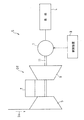
- FIG. 1 shows a gas turbine power generation system S to which the control method and control device according to the first embodiment of the present invention are applied.
- This gas turbine power generation system S is a system that generates power by driving a generator using a gas turbine engine as a prime mover.
- the gas turbine power generation system S includes a gas turbine engine (hereinafter, simply referred to as “gas turbine”) GT, a synchronous generator (hereinafter, simply referred to as “generator”) 1 driven by the gas turbine GT, and It includes a control device 3 that controls the generator 1.
- the generator 1 in this embodiment is, for example, a three-phase alternator.
- the working gas (air in this example) introduced from the outside is compressed by the compressor 5 and guided to the combustor 7 as compressed air, and the fuel is injected into the combustor 7 and burned together with the compressed air.
- the turbine 9 is driven by the obtained high-temperature and high-pressure combustion gas.
- the rotation of the turbine 9 drives the generator 1 connected to the rotor 11.
- the electric power generated by the generator 1 in this way is supplied to the load L.
- the gas turbine power generation system S is, for example, a power generation system used as an emergency power source for equipment.
- the gas turbine power generation system S supplies power to the load L by the system S alone without being connected to the system power supply.
- control method by the control device 3 according to the present embodiment will be described in detail.
- the ratio of the current value of the active power output of the gas turbine GT to the rated apparent power of the generator 1 R P n / S 100 (hereinafter, this ratio is referred to as “gas turbine output ratio”. ”)
- Exceeds the predetermined value RS (hereinafter, this predetermined value is referred to as the“ control boundary value ”) and the region below the control boundary value RS according to different rules.
- the generator 1 is set so that the apparent power is constant. Control and set the reactive power value.
- the control device 3 calculates the reactive power output from the generator 1 in the first region A1 by the following equation (1):
- Q A S 100 ⁇ ⁇ 1- (P n / S 100 ) 2 ⁇ 1/2 (1)
- P n is the current value [kW] of the active power output output from the gas turbine engine
- S 100 is the rated apparent power [kVA] of the generator 1). It is set to a value Q A obtained in.
- the control boundary value RS is set to 0.85 in advance.
- the set value of the control boundary value RS is not particularly limited, but when reactive power is supplied from other equipment, it is preferably 0.95 or less in consideration of the margin. Further, it is preferable that the set value of the control boundary value RS matches the power factor of the load L fed by the gas turbine power generation system S. From this viewpoint, it is more preferable that the control boundary value RS is set in the range of 0.8 or more and 0.9 or less, which is generally adopted as the power factor of the load L.
- the entire range of the effective power output of the gas turbine it has been performed a power factor constant control by the lagging power factor on the generator output.
- the rated power factor of the generator is required to be the delay power factor.
- the generator whose rated apparent power (rated output point S r0 ) is the value obtained by dividing the rated output of the gas turbine by the above rated power factor is selected.
- the rated output required for the generator must be a value having a margin with respect to the rated output of the gas turbine, and the physique of the generator must be increased accordingly.
- the rated output of the generator is about 18% higher than the rated output of the gas turbine. ..
- the power factor is 1, and the rated output of the generator 1 is such that the rated apparent power of the generator 1 matches the rated output of the gas turbine GT.
- the control is performed so that the apparent power of the generator 1 is not constant, but the power factor is constant. That is, the output point S 1 of the generator 1, to set the value of the reactive power Q A to move over the possible output curve L 1 of the generator 1.
- the power factor of the system power supply is not restricted.
- the control device 3 has a constant reactive power in a region (hereinafter, referred to as “second region”) A2 in which the gas turbine output ratio R is equal to or less than the control boundary value RS .
- second region A region in which the gas turbine output ratio R is equal to or less than the control boundary value RS .
- a value obtained by constant reactive power control along the line L 2 value corresponding to the output point S 2
- a value obtained by constant power factor control along the constant power factor line L 3 (corresponding to the output point S 3) .
- the value of reactive power is set by selecting the lower value from). That is, the control device 3 converts the reactive power output from the generator 1 in the second region A2 into the following equations (2) and (3).
- Q B2 (1-COS 2 ⁇ p ) 1/2 ⁇ P n / COS ⁇ p (3) (However, COS ⁇ p is a predetermined value of the power factor in the generator 1) Set to the smaller of the two values Q B1 and Q B2 obtained in.
- the active power output of the gas turbine GT is significantly increased due to some factor.
- the control method can be switched from the apparent power constant control to secure the required power factor.
- a value directly detected from the output of the generator 1 is used as the current value of the active power output (hereinafter, referred to as “current active power value”).
- current active power value P n a value detected based on the temperature of the working gas (air in this example) sucked by the gas turbine GT may be used.
- the active power value output by the gas turbine GT fluctuates. Specifically, as the intake air temperature rises, the active power output value of the gas turbine GT decreases. The fluctuation range of the active power value due to such fluctuation of the intake air temperature may reach about 30%.
- a command value of active power corresponding to a fluctuation of the intake air temperature is set in advance, and feedback control is performed based on this command value. Therefore, the active power command value corresponding to the intake air temperature fluctuation may be used as the above-mentioned active power current value P n .
- the gas turbine output value corresponding to the intake air temperature is measured by a preliminary test, and a correlation map or correlation formula between the intake air temperature and the gas turbine output is created to correspond to the measured intake air temperature.
- the current active power value P n is used.
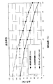
- FIG. 3 shows, as an example, the output characteristics from the gas turbine power generation system S when the generator 1 is controlled based on the intake air temperature by the method according to the present embodiment described above.
- the figure also shows, as a comparative example, the output characteristics when constant power factor control is performed over the entire conventional range.
- the vertical axis represents the gas turbine output (kW) when the maximum value of the active power output (kW) of the gas turbine GT (rated output when the intake temperature is 0 ° C.) is 100, Examples.
- the ratio of the apparent power output (kVA) of each generator 1 according to the comparative example is shown.
- the horizontal axis in the figure shows the intake air temperature.
- the gas turbine output is the output (active power output) from the gas turbine power generation system S.
- the power factor of the generator 1 is constantly controlled over the entire range of 0 ° C to 40 ° C.
- the apparent power constant control of the generator 1 is performed in the range from 0 ° C. to about 20 ° C. (first region A1 described above), and the range from about 20 ° C. to 40 ° C. (second described above).
- the reactive power constant control and the power factor constant control are controlled by low-level selection (in this example, the power factor constant control by low-level selection is performed over the entire second region A2).
- the maximum apparent power output (rated apparent power output) of the generator 1 is about 11% larger than the maximum value of the active power output of the gas turbine GT.
- the maximum apparent power output (rated apparent power output) of the generator 1 can be set to the same value as the maximum value of the active power output of the gas turbine GT.
- the rated output of the generator 1 to be adopted can be reduced by about 11% in order to obtain the same active power output from the gas turbine power generation system S.
- the ratio of the gas turbine GT output to the apparent power output of the generator 1 is higher in the example than in the comparative example. large. Therefore, the gas turbine power generation system S can be operated with higher efficiency by the method of the embodiment.
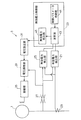
- the control device 3 includes an active power detection unit 21 and a reactive power control unit 23.
- the active power detection unit 21 detects the current value of the active power output of the gas turbine GT.
- the reactive power control unit 23 determines the value of the reactive power output from the generator 1 based on the active power output value detected by the active power detection unit 21.
- the control device 3 also includes a reactive power detection unit 25, a voltage detection unit 27, a current detection unit 29, a voltage setting unit 31, a voltage adjustment unit 33, and an excitation unit 35.
- the voltage detection unit 27 detects the output voltage of the generator 1.
- the voltage detection unit 27 is configured as a voltage transformer in this example.
- the current detection unit 29 detects the output current of the generator 1.
- the current detection unit 29 is configured as an instrument transformer.
- the reactive power detection unit 25 is connected to the voltage detection unit 27 and the current detection unit 29, and the output voltage value of the generator 1 input from the voltage detection unit 27 and the output of the generator 1 input from the current detection unit 29.
- the output value of reactive power is detected from the current value.
- the active power detection unit 21 is connected to the voltage detection unit 27 and the current detection unit 29, and the output voltage value of the generator 1 input from the voltage detection unit 27 and the output of the generator 1 input from the current detection unit 29. The output value of active power is detected from the current value.
- the reactive power control unit 23 includes a control parameter storage unit 41, a calculation unit 43, and a reactive power indicator unit 45.
- the control parameter storage unit 41 has a rated apparent power value S 100 of the generator 1, a maximum reactive power value Q max , and a control boundary value RS , which are constant parameters necessary for executing the control method described above by the control device 3. , A predetermined value COS ⁇ p of the power factor when the power factor is constantly controlled in the second region A2 is stored. The control parameter storage unit 41 outputs these stored parameters to the calculation unit 43 as needed. When the control is performed based on the intake air temperature described above, the correlation map between the intake air temperature and the active power output can also be stored in the control parameter storage unit 41.
- the calculation unit 43 uses any of the above equations (1) to (3) from the current value of the active power input from the active power detection unit 21 and the control parameters stored in the control parameter storage unit 41. Calculate the target values Q A , Q B1 and Q B 2 of reactive power. Calculator 43, further, the reactive power target value Q A, and Q B1, Q B2, and calculates the difference between the current value of the input reactive power from the reactive power detector 25.
- the reactive power indicator 45 sends a control command value based on the deviation of the reactive power calculated by the calculation unit 43 to the voltage setting unit 31.
- the voltage setting unit 31 sets the output voltage of the generator 1 based on the command from the reactive power indicator unit 45.
- the voltage adjusting unit 33 adjusts the output voltage of the generator 1 based on the output voltage of the generator 1 set by the voltage setting unit 31.
- the exciting unit 35 excites the generator 1 in accordance with a command from the voltage adjusting unit 33.
- the apparent power of the generator 1 is constant in the region where the active power output of the gas turbine GT is close to the maximum value.
- the reduced amount can be output as the ineffective power of the generator 1, so that the performance of the generator 1 can be fully utilized. can do.
- this control method is not the conventional control for keeping the delay power factor constant, the maximum apparent power output (rated apparent power output) of the generator 1 when the power factor of the generator 1 is 1 is set to gas. It can be the same value as the maximum value of the active power output of the turbine GT. That is, since the rated output and physique of the generator 1 to be adopted can be made smaller than the rated output of the gas turbine power generation system S as compared with the conventional one, the control method and the control device 3 are applied. The efficiency and miniaturization of the gas turbine power generation system S can be improved.
- the current value Pn of the active power output may be detected based on the temperature of the working gas sucked by the gas turbine GT.
- the output of the gas turbine GT during rated operation may fluctuate by several tens of percent depending on the temperature of the working gas to be sucked.
- the output of the gas turbine GT is an active power command corresponding to the fluctuation of the working gas temperature set in advance. It is controlled based on the value. Therefore, by using this command value as the current value of the active power output, the process of controlling the apparent power constant of the reactive power is simplified, and the amount of decrease in the active power value due to the fluctuation of the working gas temperature is output as the reactive power. Will be possible.
- the reactive power output from the generator 1 is subjected to the following equations (2) and (3) in the range where the ratio R is 0 ⁇ R ⁇ Rs.
- Q B2 (1-COS 2 ⁇ p ) 1/2 ⁇ P n / COS ⁇ p (3) (However, COS ⁇ p is a predetermined value of the power factor in the generator 1) You may set it to the smaller of the two values Q B1 and Q B2 obtained in. According to this configuration, when the active power output of the gas turbine GT is significantly reduced due to some factor, the control method is switched from the apparent power constant control to the reactive power constant control or the power factor constant control, and the required power factor is obtained. Can be secured.
- the predetermined value Rs of the ratio R may be set in advance in the range of 0.8 or more and 0.95 or less. According to this configuration, the required power factor can be surely secured by adjusting the lower limit of the region where the apparent power constant control is performed to the power factor of a general load.
- the gas turbine power generation system S includes a gas turbine GT, a synchronous generator 1 driven by the gas turbine GT, and the control device 3 for controlling the generator 1. According to this configuration, by adopting the control method and the control device having the above-mentioned effects, it is possible to improve the efficiency and miniaturize the gas turbine power generation system S.
- Control device 21 Active power detection unit 23 Reactive power control unit GT Gas turbine engine S Gas turbine power generation system
Landscapes
- Engineering & Computer Science (AREA)
- Power Engineering (AREA)
- Chemical & Material Sciences (AREA)
- Combustion & Propulsion (AREA)
- Mechanical Engineering (AREA)
- General Engineering & Computer Science (AREA)
- Control Of Eletrric Generators (AREA)
Abstract
ガスタービンエンジン(GT)と、前記ガスタービンエンジンによって駆動される同期型の発電機(1)とを備えるガスタービン発電システム(S)を制御する方法において、前記発電機から出力される無効電力を、前記発電機の定格皮相電力に対する前記ガスタービンエンジンの有効電力出力の現在値の比率R=Pn/S100が所定値Rs<R≦1である範囲において、下記の式(1) QA=S100×{1-(Pn/S100)2}1/2 (1) (ただし、Pnは前記ガスタービンエンジンから出力された有効電力出力の現在値[kW],S100は前記発電機の定格皮相電力[kVA])で得られる値QAに設定する。
Description
本出願は、2019年6月25日出願の特願2019-117709の優先権を主張するものであり、その全体を参照により本願の一部をなすものとして引用する。
本発明は、ガスタービンエンジンを原動機とする発電システム(以下、「ガスタービン発電システム」という。)を制御する方法および装置に関する。
発電設備として、原動機であるガスタービンエンジンと、これによって駆動される同期型発電機とを組み合わせたガスタービン発電システムが広く使用されている(例えば、特許文献1,2参照)。従来、ガスタービン発電システムでは、力率が一定になるように無効電力出力が制御されている。
しかし、通常、ガスタービンエンジンの有効電力出力は、例えば吸気温度の変化といった要因の影響によって数十%程度変動し得る。その場合、このガスタービンエンジンと組み合わせる発電機の定格出力は、ガスタービンエンジンの最大の有効電力出力に合わせることになるので、ガスタービンエンジンが最大出力より低い出力領域で作動する期間は、発電機の性能(皮相電力出力能力)を十分に活用できない。
そこで、本発明の目的は、上記の課題を解決するために、ガスタービンエンジンに出力変動が生じる場合にも、発電機の発電能力を十分に活用することができるガスタービン発電システムの制御方法および制御装置を提供することにある。
前記した目的を達成するために、本発明に係るガスタービン発電システムの制御方法は、ガスタービンエンジンと、前記ガスタービンエンジンによって駆動される同期型の発電機とを備えるガスタービン発電システムを制御する方法であって、
前記発電機から出力される無効電力を、前記発電機の定格皮相電力に対する前記ガスタービンエンジンの有効電力出力の現在値の比率R=Pn/S100が所定値Rs<R≦1である範囲において、下記の式(1)
QA=S100×{1-(Pn/S100)2}1/2 (1)
(ただし、Pnは前記ガスタービンエンジンから出力された有効電力出力の現在値[kW],S100は前記発電機の定格皮相電力[kVA])
で得られる値QAに設定することを含む。
前記発電機から出力される無効電力を、前記発電機の定格皮相電力に対する前記ガスタービンエンジンの有効電力出力の現在値の比率R=Pn/S100が所定値Rs<R≦1である範囲において、下記の式(1)
QA=S100×{1-(Pn/S100)2}1/2 (1)
(ただし、Pnは前記ガスタービンエンジンから出力された有効電力出力の現在値[kW],S100は前記発電機の定格皮相電力[kVA])
で得られる値QAに設定することを含む。
また、本発明に係るガスタービン発電システムの制御装置は、
ガスタービンエンジンと、前記ガスタービンエンジンによって駆動される同期型の発電機とを備えるガスタービン発電システムを制御する装置であって、
前記ガスタービンエンジンの有効電力出力を検出する有効電力検出部と、
前記発電機から出力される無効電力を、前記発電機の定格皮相電力に対する前記ガスタービンエンジンの有効電力出力の現在値の比率R=Pn/S100が所定値Rs<R≦1である範囲において、下記の式(1)
QA=S100×{1-(Pn/S100)2}1/2 (1)
(ただし、Pnは前記ガスタービンエンジンから出力された有効電力出力の現在値[kW],S100は前記発電機の定格皮相電力[kVA])
で得られる値QAに設定する無効電力制御部を備える。
この構成によれば、ガスタービンエンジンの通常の作動領域である有効電力出力が最大値(定格値)に近い領域において、発電機の出力を皮相電力が一定となるように制御する。これにより、ガスタービンエンジンの有効電力出力が最大値から低下した場合、その低下分を発電機の無効電力として出力することができるので、発電機の性能を十分に活用することができる。さらに、この制御方法は、従来の遅れ力率を一定にする制御ではないので、発電機の力率が1である場合の発電機の最大皮相電力出力(定格皮相電力出力)を、ガスタービンの有効電力出力の最大値と同じ値とすることができる。すなわち、当該ガスタービン発電システムの定格出力に対して、採用する発電機の定格出力、体格を従来に比べて小さいものとすることができる。
請求の範囲および/または明細書および/または図面に開示された少なくとも2つの構成のどのような組合せも、本発明に含まれる。特に、請求の範囲の各請求項の2つ以上のどのような組合せも、本発明に含まれる。
この発明は、添付の図面を参考にした以下の好適な実施形態の説明から、より明瞭に理解されるであろう。しかしながら、実施形態および図面は単なる図示および説明のためのものであり、この発明の範囲を定めるために利用されるべきものではない。この発明の範囲は添付の請求の範囲によって定まる。添付図面において、複数の図面における同一の符号は、同一または相当する部分を示す。
本発明の一実施形態に係る制御方法および制御装置が適用されるガスタービン発電システムの概略構成を示すブロック図である。
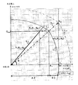
本発明の一実施形態に係る制御方法の原理を従来技術と比較して示す発電機出力可能曲線図である。
本発明の一実施形態に係る制御方法の効果を説明するグラフである。
本発明の一実施形態に係る制御装置の概略構成を示すブロック図である。
以下、本発明に係る実施形態を図面に従って説明する。図1に、本発明の第1実施形態に係る制御方法および制御装置が適用されるガスタービン発電システムSを示す。このガスタービン発電システムSは、ガスタービンエンジンを原動機として発電機を駆動することによって発電するシステムである。ガスタービン発電システムSは、ガスタービンエンジン(以下、単に「ガスタービン」という。)GTと、ガスタービンGTによって駆動される同期型の発電機(以下、単に「発電機」という。)1と、発電機1を制御する制御装置3とを備えている。本実施形態における発電機1は、例えば三相交流発電機である。
ガスタービンGTは、外部から導入された作動ガス(この例では空気)を圧縮機5で圧縮して圧縮空気として燃焼器7に導き、燃料を燃焼器7内に噴射して圧縮空気とともに燃焼させ、得られた高温高圧の燃焼ガスによりタービン9を駆動する。タービン9の回転によって、ロータ11に連結された発電機1が駆動される。このようにして発電機1で生成された電力が負荷Lに供給される。ガスタービン発電システムSは、例えば設備の非常用電源として使用される発電システムである。ガスタービン発電システムSは、系統電源と連系することなく、当該システムS単独で負荷Lに給電する。
以下、本実施形態に係る制御装置3による制御方法について詳細に説明する。
図2に示すように、制御装置3は、発電機1の定格皮相電力に対するガスタービンGTの有効電力出力の現在値の比率R=Pn/S100(以下、この比率を「ガスタービン出力比率」と呼ぶ。)が所定値RS(以下、この所定値を「制御境界値」と呼ぶ。)を超える領域と、制御境界値RS以下の領域とで、異なる規則によって、無効電力制御を行う。具体的には、ガスタービン出力比率Rが制御境界値RSより大かつ1以下の領域(以下、「第1領域」と呼ぶ。)A1では、皮相電力が一定となるように発電機1を制御して無効電力の値を設定する。すなわち、制御装置3は、第1領域A1において、発電機1から出力される無効電力を、下記式(1):
QA=S100×{1-(Pn/S100)2}1/2 (1)
(ただし、Pnは前記ガスタービンエンジンから出力された有効電力出力の現在値[kW],S100は前記発電機1の定格皮相電力[kVA])
で得られる値QAに設定する。
QA=S100×{1-(Pn/S100)2}1/2 (1)
(ただし、Pnは前記ガスタービンエンジンから出力された有効電力出力の現在値[kW],S100は前記発電機1の定格皮相電力[kVA])
で得られる値QAに設定する。
本実施形態では、制御境界値RSを予め0.85に設定している。なお、制御境界値RSの設定値は特に限定されないが、他の設備から無効電力が供給される場合においては、裕度を考慮して0.95以下とすることが好ましい。さらに、制御境界値RSの設定値は、当該ガスタービン発電システムSによって給電される負荷Lの力率に一致させることが好ましい。この観点から、制御境界値RSは、負荷Lの力率として一般的に採用されている0.8以上0.9以下の範囲で設定することがより好ましい。
従来は、一般的に、図2において一点鎖線L0で示すように、ガスタービンの有効電力出力の全範囲において、発電機出力について遅れ力率による力率一定制御を行っていた。典型的には、発電機から系統電源へ電力供給する場合には、その発電機の定格力率を遅れ力率とすることが要求される。その場合、発電機の定格皮相電力(定格出力点Sr0)が、ガスタービンの定格出力を上記定格力率で除した値となる発電機を選択することになる。したがって、ガスタービンの有効電力出力が何らかの要因(例えば、後述するように吸気温度の変化)によって低下したときは、発電機を出力可能曲線(二点鎖線で示す線LX)よりも内側で作動させることになり、発電機の発電能力(定格皮相電力)を十分に活用できない。また、発電機に要求される定格出力は、ガスタービンの定格出力に対してマージンを有する値にせざるを得ず、これに応じて発電機の体格も大きなものとならざるを得ない。例えば、定格力率を、上述の制御境界値RSとした0.85とする力率一定制御の場合、発電機の定格出力は、ガスタービンの定格出力に対して約18%上回ることになる。
これに対して、本実施形態では、第1領域A1においては、力率が1であり、かつ発電機1の定格皮相電力がガスタービンGTの定格出力に一致するように発電機1の定格出力点Sr1を設定したうえで、力率を一定とするのではなく、発電機1の皮相電力を一定とする制御を行う。すなわち、発電機1の出力点S1が、発電機1の出力可能曲線L1上を動くように無効電力QAの値を設定する。本実施形態に係るガスタービン発電システムSのように、系統電源に電力供給を行わない場合には、系統電源の力率の制約を受けないので、このような制御が可能になる。発電機1をこのように制御することにより、発電機1が有する発電能力(定格皮相電力)を十分に活用して、ガスタービンGTの有効電力出力が低下した場合には、その分を無効電力として出力することが可能になる。
本実施形態では、同図に示すように、制御装置3は、ガスタービン出力比率Rが制御境界値RS以下である領域(以下、「第2領域」と呼ぶ。)A2において、無効電力一定線L2に沿った無効電力一定制御によって得られる値(出力点S2に対応する値)と、力率一定線L3に沿った力率一定制御によって得られる値(出力点S3に対応する値)とからの低位選択によって無効電力の値を設定する。すなわち、制御装置3は、第2領域A2において、発電機1から出力される無効電力を、下記の式(2)および式(3)
QB1=Qmax (2)
(ただし、Qmaxは式(1)において前記ガスタービン出力比率R=Rsの場合の無効電力の値)
QB2=(1-COS2θp)1/2×Pn/COSθp (3)
(ただし、COSθpは前記発電機1における力率の所定値)
で得られる2つの値QB1,QB2のうち小さい方の値に設定する。
QB1=Qmax (2)
(ただし、Qmaxは式(1)において前記ガスタービン出力比率R=Rsの場合の無効電力の値)
QB2=(1-COS2θp)1/2×Pn/COSθp (3)
(ただし、COSθpは前記発電機1における力率の所定値)
で得られる2つの値QB1,QB2のうち小さい方の値に設定する。
通常想定される作動領域である第1領域A1において上記の皮相電力一定制御を行いながら、第2領域A2においてこのような制御を行うことにより、ガスタービンGTの有効電力出力が何らかの要因により大幅に低下した場合には、制御方式を皮相電力一定制御から切り替えて、必要な力率を確保することができる。
なお、本実施形態においては、後に詳述するように、有効電力出力の現在値(以下、「有効電力現在値」という。)として、発電機1の出力から直接検出した値を用いているが、有効電力現在値Pnとして、ガスタービンGTが吸入する作動ガス(この例では空気)の温度に基づいて検出した値を用いてもよい。
一般的に、年間を通じてガスタービンGTの吸気温度が変化することにより、ガスタービンGTが出力する有効電力値が変動する。具体的には、吸気温度が上昇するにしたがって、ガスタービンGTの有効電力出力値が低下する。このような吸気温度の変動による有効電力値の変動幅は、30%程度に至る場合もある。通常、ガスタービンGTの運転においては、吸気温度の変動に応じた有効電力の指令値を予め設定し、この指令値に基づいたフィードバック制御を行っている。そこで、この吸気温度変動に対応した有効電力指令値を、上記の有効電力現在値Pnとして用いてもよい。このように制御することにより、無効電力の皮相電力一定制御のプロセスを簡易化しながら、吸気温度の変動によって有効電力値が低下した分を無効電力として出力することが可能になる。
具体的には、例えば、事前の試験によって吸気温度に対応するガスタービン出力値を測定しておき、吸気温度とガスタービン出力との相関マップまたは相関式を作成して、測定した吸気温度に対応する有効電力現在値Pnを使用する。
なお、ガスタービンGTの有効電力出力を低下させる要因が吸気温度以外にない場合には、有効電力現在値として発電機1の出力から直接検出した値と、吸気温度に対応する設定指令値とはほぼ一致するから、制御結果もほぼ同一となる。吸気温度変動以外の他の要因の影響により有効電力出力が変動することが予め想定される場合には、当該他の要因に基づく変動も考慮に入れた相関マップ等を用意してもよい。
図3に、実施例として、上述した本実施形態に係る方法によって吸気温度に基づいて発電機1を制御した場合のガスタービン発電システムSからの出力特性を示す。同図には、比較例として、従来の全範囲に渡って力率一定制御を行った場合の出力特性も示している。同図において、縦軸は、ガスタービンGTの有効電力出力(kW)の最大値(吸気温度が0℃のときの定格出力)を100としたときの、ガスタービン出力(kW)、実施例、比較例に係る各発電機1の皮相電力出力(kVA)の割合を示す。また、同図の横軸は吸気温度を示す。なお、ガスタービン出力は当該ガスタービン発電システムSからの出力(有効電力出力)となる。
上述のように、比較例においては、0℃~40℃の全範囲に渡って発電機1を力率一定制御している。他方、実施例においては、0℃~約20℃までの範囲(上述の第1領域A1)において発電機1の皮相電力一定制御がなされ、約20℃~40℃までの範囲(上述の第2領域A2)において無効電力一定制御と力率一定制御との低位選択による制御(この例では、第2領域A2全体に渡って低位選択による力率一定制御)がなされている。
同図からわかるように、比較例においては、発電機1の最大皮相電力出力(定格皮相電力出力)が、ガスタービンGTの有効電力出力の最大値に対して約11%大きいのに対して、実施例においては、発電機1の最大皮相電力出力(定格皮相電力出力)を、ガスタービンGTの有効電力出力の最大値と同じ値とすることができる。換言すれば、本実施形態に係る制御方法を採用することにより、ガスタービン発電システムSから同等の有効電力出力を得るために、採用する発電機1の定格出力を約11%下げることができる。また、同図から明らかなように、吸気温度0℃~約20℃までの範囲においては、比較例に比べて実施例の方が、発電機1の皮相電力出力に対するガスタービンGT出力の比率が大きい。したがって、実施例の方法によってガスタービン発電システムSをより高効率で運転することができる。
次に、上記で説明した制御方法を実行するための制御装置3の構成例について説明する。
図4に示すように、制御装置3は、有効電力検出部21と、無効電力制御部23とを備えている。有効電力検出部21は、ガスタービンGTの有効電力出力の現在値を検出する。無効電力制御部23は、有効電力検出部21によって検出した有効電力出力値に基づいて、発電機1から出力される無効電力の値を決定する。本実施形態において、制御装置3は、そのほかに、無効電力検出部25、電圧検出部27、電流検出部29、電圧設定部31、電圧調整部33、および励磁部35を備えている。
電圧検出部27は、発電機1の出力電圧を検出する。電圧検出部27は、この例では計器用変圧器として構成されている。電流検出部29は、発電機1の出力電流を検出する。電流検出部29は、この例では、計器用変流器として構成されている。
無効電力検出部25は、電圧検出部27および電流検出部29に接続されて、電圧検出部27から入力された発電機1の出力電圧値および電流検出部29から入力された発電機1の出力電流値から、無効電力の出力値を検出する。有効電力検出部21は、電圧検出部27および電流検出部29に接続されて、電圧検出部27から入力された発電機1の出力電圧値および電流検出部29から入力された発電機1の出力電流値から、有効電力の出力値を検出する。
無効電力制御部23は、制御パラメータ格納部41と、演算部43と、無効電力指示部45とを備えている。
制御パラメータ格納部41は、制御装置3による上述した制御方法を実行するために必要な定数パラメータである、発電機1の定格皮相電力値S100、最大無効電力値Qmax、制御境界値RS、第2領域A2において力率一定制御をする場合の力率の所定値COSθp等を格納する。制御パラメータ格納部41は、格納したこれらのパラメータを、必要に応じて演算部43に出力する。上述した吸気温度に基づくよる制御を行う場合には、吸気温度と有効電力出力の相関マップも制御パラメータ格納部41に格納しておくことができる。
演算部43は、有効電力検出部21から入力された有効電力の現在値と、制御パラメータ格納部41に格納された制御パラメータとから、上記式(1)~(3)のいずれかを用いて無効電力の目標値QA,QB1,QB2を算出する。演算部43は、さらに、この無効電力目標値QA,QB1,QB2と、無効電力検出部25から入力された無効電力の現在値との偏差を算出する。無効電力指示部45は、演算部43で算出された無効電力の偏差に基づく制御指令値を電圧設定部31に送る。
電圧設定部31は、無効電力指示部45からの指令に基づいて発電機1の出力電圧を設定する。電圧調整部33は、電圧設定部31によって設定された発電機1の出力電圧に基づいて、発電機1の出力電圧を調整する。励磁部35は、電圧調整部33からの指令に従って発電機1を励磁する。
以上説明した本実施形態に係るガスタービン発電システムSの制御方法および制御装置3によれば、ガスタービンGTの有効電力出力が最大値に近い領域において、発電機1の出力を皮相電力が一定となるように制御することにより、ガスタービンエンジンの有効電力出力が最大値から低下した場合、その低下分を発電機1の無効電力として出力することができるので、発電機1の性能を十分に活用することができる。
さらに、この制御方法は、従来の遅れ力率を一定にする制御ではないので、発電機1の力率が1である場合の発電機1の最大皮相電力出力(定格皮相電力出力)を、ガスタービンGTの有効電力出力の最大値と同じ値とすることができる。すなわち、当該ガスタービン発電システムSの定格出力に対して、採用する発電機1の定格出力、体格を従来に比べて小さいものとすることができるので、当該制御方法および制御装置3が適用されるガスタービン発電システムSの高効率化および小型化を図ることができる。
また、上述したように、本発明の一実施形態において、前記有効電力出力の現在値Pnを、前記ガスタービンGTが吸入する作動ガスの温度に基づいて検出してもよい。ガスタービンGTの定格運転時の出力は、吸入する作動ガスの温度によって数十%変動する場合があり、通常、ガスタービンGTの出力は、予め設定した作動ガス温度の変動に対応する有効電力指令値に基づいて制御されている。そこで、この指令値を有効電力出力の現在値として用いることにより、無効電力の皮相電力一定制御のプロセスを簡易化しながら、作動ガス温度の変動によって有効電力値が低下した分を無効電力として出力することが可能になる。
本発明の一実施形態において、前記発電機1から出力される無効電力を、前記比率Rが0≦R≦Rsの範囲において、下記の式(2)および式(3)
QB1=Qmax (2)
(ただし、Qmaxは式(1)において前記比率R=Rsの場合の無効電力の値)
QB2=(1-COS2θp)1/2×Pn/COSθp (3)
(ただし、COSθpは前記発電機1における力率の所定値)
で得られる2つの値QB1,QB2のうち小さい方の値に設定してもよい。この構成によれば、ガスタービンGTの有効電力出力が何らかの要因により大幅に低下した場合には、制御方式を皮相電力一定制御から無効電力一定制御または力率一定制御に切り替えて、必要な力率を確保することができる。
QB1=Qmax (2)
(ただし、Qmaxは式(1)において前記比率R=Rsの場合の無効電力の値)
QB2=(1-COS2θp)1/2×Pn/COSθp (3)
(ただし、COSθpは前記発電機1における力率の所定値)
で得られる2つの値QB1,QB2のうち小さい方の値に設定してもよい。この構成によれば、ガスタービンGTの有効電力出力が何らかの要因により大幅に低下した場合には、制御方式を皮相電力一定制御から無効電力一定制御または力率一定制御に切り替えて、必要な力率を確保することができる。
本発明の一実施形態において、前記比率Rの所定値Rsを予め0.8以上0.95以下の範囲で設定してもよい。この構成によれば、皮相電力一定制御を行う領域の下限を一般的な負荷の力率に合わせることによって、確実に必要な力率を確保することができる。
本発明に係るガスタービン発電システムSは、ガスタービンGTと、前記ガスタービンGTによって駆動される同期型の発電機1と、前記発電機1を制御する前記制御装置3とを備えている。この構成によれば、上述の効果を有する制御方法、制御装置を採用することにより、ガスタービン発電システムSの高効率化、小型化を図ることができる。
以上のとおり、図面を参照しながら本発明の好適な実施形態を説明したが、本発明の趣旨を逸脱しない範囲内で、種々の追加、変更または削除が可能である。したがって、そのようなものも本発明の範囲内に含まれる。
1 発電機
3 制御装置
21 有効電力検出部
23 無効電力制御部
GT ガスタービンエンジン
S ガスタービン発電システム
3 制御装置
21 有効電力検出部
23 無効電力制御部
GT ガスタービンエンジン
S ガスタービン発電システム
Claims (9)
- ガスタービンエンジンと、前記ガスタービンエンジンによって駆動される同期型の発電機とを備えるガスタービン発電システムを制御する方法であって、
前記発電機から出力される無効電力を、前記発電機の定格皮相電力に対する前記ガスタービンエンジンの有効電力出力の現在値の比率R=Pn/S100が所定値Rs<R≦1である範囲において、下記の式(1)
QA=S100×{1-(Pn/S100)2}1/2 (1)
(ただし、Pnは前記ガスタービンエンジンから出力された有効電力出力の現在値[kW],S100は前記発電機の定格皮相電力[kVA])
で得られる値QAに設定することを含む、
ガスタービン発電システムの制御方法。 - 請求項1に記載の制御方法において、
前記有効電力出力の現在値Pnを、前記ガスタービンエンジンが吸入する作動ガスの温度に基づいて検出することを含む制御方法。 - 請求項1または2に記載の制御方法において、
前記発電機から出力される無効電力を、前記比率Rが0≦R≦Rsの範囲において、下記の式(2)および式(3)
QB1=Qmax (2)
(ただし、Qmaxは式(1)において前記比率R=Rsの場合の無効電力の値)
QB2=(1-COS2θp)1/2×Pn/COSθp (3)
(ただし、COSθpは前記発電機における力率の所定値)
で得られる2つの値QB1,QB2のうち小さい方の値に設定することを含む、
制御方法。 - 請求項1から3のいずれか一項に記載の制御方法において、前記比率Rの所定値Rsを予め0.8以上0.95以下の範囲で設定することを含む制御方法。
- ガスタービンエンジンと、前記ガスタービンエンジンによって駆動される同期型の発電機とを備えるガスタービン発電システムを制御する装置であって、
前記ガスタービンエンジンの有効電力出力を検出する有効電力検出部と、
前記発電機から出力される無効電力を、前記発電機の定格皮相電力に対する前記ガスタービンエンジンの有効電力出力の現在値の比率R=Pn/S100が所定値Rs<R≦1である範囲において、下記の式(1)
QA=S100×{1-(Pn/S100)2}1/2 (1)
(ただし、Pnは前記ガスタービンエンジンから出力された有効電力出力の現在値[kW],S100は前記発電機の定格皮相電力[kVA])
で得られる値QAに設定する無効電力制御部を備える、
ガスタービン発電システムの制御装置。 - 請求項5に記載の制御装置において、
前記有効電力検出部が、前記現在値Pnを、前記ガスタービンエンジンが吸入する作動ガスの温度に基づいて検出するように構成されている
制御装置。 - 請求項5または6に記載の制御装置において、
前記無効電力制御部は、
前記発電機から出力される無効電力を、前記比率Rが0≦R≦Rsの範囲において、下記の式(2)および式(3)
QB1=Qmax (2)
(ただし、Qmaxは式(1)において前記比率R=Rsの場合の無効電力の値)
QB2=(1-COS2θp)1/2×Pn/COSθp (3)
(ただし、COSθpは前記発電機における力率の所定値)
で得られる2つの値QB1,QB2のうち小さい方の値に設定する
制御装置。 - 請求項5から7のいずれか一項に記載の制御装置において、
前記比率Rの所定値Rsが予め0.8以上0.95以下の範囲で設定されている
制御装置。 - ガスタービンエンジンと、
前記ガスタービンエンジンによって駆動される同期型の発電機と、
前記発電機を制御する、請求項5から8のいずれか一項に記載の制御装置と、
を備えるガスタービン発電システム。
Priority Applications (1)
| Application Number | Priority Date | Filing Date | Title |
|---|---|---|---|
| CN202080046644.8A CN114402522B (zh) | 2019-06-25 | 2020-06-19 | 燃气轮机发电系统的控制方法及控制装置 |
Applications Claiming Priority (2)
| Application Number | Priority Date | Filing Date | Title |
|---|---|---|---|
| JP2019117709A JP7353823B2 (ja) | 2019-06-25 | 2019-06-25 | ガスタービン発電システムの制御方法および制御装置 |
| JP2019-117709 | 2019-06-25 |
Publications (1)
| Publication Number | Publication Date |
|---|---|
| WO2020262235A1 true WO2020262235A1 (ja) | 2020-12-30 |
Family
ID=74061614
Family Applications (1)
| Application Number | Title | Priority Date | Filing Date |
|---|---|---|---|
| PCT/JP2020/024146 Ceased WO2020262235A1 (ja) | 2019-06-25 | 2020-06-19 | ガスタービン発電システムの制御方法および制御装置 |
Country Status (3)
| Country | Link |
|---|---|
| JP (1) | JP7353823B2 (ja) |
| CN (1) | CN114402522B (ja) |
| WO (1) | WO2020262235A1 (ja) |
Citations (3)
| Publication number | Priority date | Publication date | Assignee | Title |
|---|---|---|---|---|
| JPS6416300A (en) * | 1987-07-10 | 1989-01-19 | Hitachi Ltd | Controller for gas turbine generator |
| JPH1028399A (ja) * | 1996-07-08 | 1998-01-27 | Mitsubishi Electric Corp | 発電機制御方式 |
| US20180198394A1 (en) * | 2017-01-11 | 2018-07-12 | General Electric Company | Generator stabilization |
Family Cites Families (3)
| Publication number | Priority date | Publication date | Assignee | Title |
|---|---|---|---|---|
| JPH0621399U (ja) * | 1992-08-17 | 1994-03-18 | 東芝エンジニアリング株式会社 | 発電機容量制限装置 |
| US20040085046A1 (en) * | 2002-11-01 | 2004-05-06 | General Electric Company | Power conditioning system for turbine motor/generator |
| KR100886194B1 (ko) * | 2007-06-08 | 2009-02-27 | 한국전기연구원 | 계통 연계형 고압 권선형 유도 발전기 제어 장치 |
-
2019
- 2019-06-25 JP JP2019117709A patent/JP7353823B2/ja active Active
-
2020
- 2020-06-19 WO PCT/JP2020/024146 patent/WO2020262235A1/ja not_active Ceased
- 2020-06-19 CN CN202080046644.8A patent/CN114402522B/zh active Active
Patent Citations (3)
| Publication number | Priority date | Publication date | Assignee | Title |
|---|---|---|---|---|
| JPS6416300A (en) * | 1987-07-10 | 1989-01-19 | Hitachi Ltd | Controller for gas turbine generator |
| JPH1028399A (ja) * | 1996-07-08 | 1998-01-27 | Mitsubishi Electric Corp | 発電機制御方式 |
| US20180198394A1 (en) * | 2017-01-11 | 2018-07-12 | General Electric Company | Generator stabilization |
Also Published As
| Publication number | Publication date |
|---|---|
| JP2021005923A (ja) | 2021-01-14 |
| JP7353823B2 (ja) | 2023-10-02 |
| CN114402522A (zh) | 2022-04-26 |
| CN114402522B (zh) | 2024-02-13 |
Similar Documents
| Publication | Publication Date | Title |
|---|---|---|
| US7915868B1 (en) | Method of synchronizing a turbomachine generator to an electric grid | |
| JP5167106B2 (ja) | 風力発電所とその発電制御方法 | |
| US9444391B2 (en) | Protective module and method against torque peaks between a motor and an electric machine | |
| US8111048B2 (en) | Double fed synchronous generator motor | |
| US20070031238A1 (en) | Inlet guide vane control device of gas turbine | |
| JP2018505635A (ja) | ガスタービン発電システムおよびそれに用いる制御システム | |
| JP3677536B2 (ja) | ガスタービン発電制御装置 | |
| US6163078A (en) | Adjustable speed gas turbine power generation apparatus and its operation method | |
| US20130145772A1 (en) | Method of operating a combined cycle power plant | |
| JP2008199848A (ja) | 同期発電機の励磁制御装置 | |
| US8692521B2 (en) | Method and apparatus for controlling torque on the shaft of a generator | |
| JP7353823B2 (ja) | ガスタービン発電システムの制御方法および制御装置 | |
| CN111684150B (zh) | 燃气轮机的控制装置、燃气轮机及燃气轮机的控制方法 | |
| JP4685715B2 (ja) | 電源系統安定化方法及びその方法を用いた電源系統安定化システム | |
| US10344680B2 (en) | Method for regulating a gas turbine power supply | |
| EP3913766A1 (en) | Electric power control device and electric power control method | |
| US10900416B2 (en) | Gas turbine system and control apparatus and method thereof | |
| JP2010156308A (ja) | ガスタービン・エンジンの制御装置 | |
| JP2002218657A (ja) | 電力発電システム | |
| JP3155897B2 (ja) | ガスタービン発電機の制御装置 | |
| JP3790512B2 (ja) | ガスタービン発電プラント及びその制御方法,並びにガスタービン制御装置 | |
| JP7016599B1 (ja) | 発電装置の制御方法 | |
| JP2012191715A (ja) | ディーゼル動車駆動装置の制御システム | |
| RU2729584C1 (ru) | Способ управления турбогенератором | |
| JP2020193566A (ja) | ガスタービンの制御装置、ガスタービン、発電設備、ガスタービンの制御方法及びプログラム |
Legal Events
| Date | Code | Title | Description |
|---|---|---|---|
| 121 | Ep: the epo has been informed by wipo that ep was designated in this application |
Ref document number: 20832559 Country of ref document: EP Kind code of ref document: A1 |
|
| NENP | Non-entry into the national phase |
Ref country code: DE |
|
| 122 | Ep: pct application non-entry in european phase |
Ref document number: 20832559 Country of ref document: EP Kind code of ref document: A1 |