WO2020262128A1 - コネクタ装置 - Google Patents
コネクタ装置 Download PDFInfo
- Publication number
- WO2020262128A1 WO2020262128A1 PCT/JP2020/023690 JP2020023690W WO2020262128A1 WO 2020262128 A1 WO2020262128 A1 WO 2020262128A1 JP 2020023690 W JP2020023690 W JP 2020023690W WO 2020262128 A1 WO2020262128 A1 WO 2020262128A1
- Authority
- WO
- WIPO (PCT)
- Prior art keywords
- connector
- terminal
- terminals
- electrode terminal
- positive electrode
- Prior art date
- Legal status (The legal status is an assumption and is not a legal conclusion. Google has not performed a legal analysis and makes no representation as to the accuracy of the status listed.)
- Ceased
Links
Images






Classifications
-
- H—ELECTRICITY
- H01—ELECTRIC ELEMENTS
- H01R—ELECTRICALLY-CONDUCTIVE CONNECTIONS; STRUCTURAL ASSOCIATIONS OF A PLURALITY OF MUTUALLY-INSULATED ELECTRICAL CONNECTING ELEMENTS; COUPLING DEVICES; CURRENT COLLECTORS
- H01R13/00—Details of coupling devices of the kinds covered by groups H01R12/70 or H01R24/00 - H01R33/00
- H01R13/02—Contact members
- H01R13/22—Contacts for co-operating by abutting
- H01R13/24—Contacts for co-operating by abutting resilient; resiliently-mounted
-
- H—ELECTRICITY
- H01—ELECTRIC ELEMENTS
- H01R—ELECTRICALLY-CONDUCTIVE CONNECTIONS; STRUCTURAL ASSOCIATIONS OF A PLURALITY OF MUTUALLY-INSULATED ELECTRICAL CONNECTING ELEMENTS; COUPLING DEVICES; CURRENT COLLECTORS
- H01R24/00—Two-part coupling devices, or either of their cooperating parts, characterised by their overall structure
- H01R24/38—Two-part coupling devices, or either of their cooperating parts, characterised by their overall structure having concentrically or coaxially arranged contacts
Definitions
- the present invention relates to a connector device.
- the connector device used for connecting a battery and an inverter in an automobile, an electric motorcycle, or the like includes a first connector having a plurality of first terminals and a plurality of second terminals electrically connected to the plurality of first terminals. It is provided with a second connector having a (see, for example, Patent Document 1). One of the first connector and the second connector is electrically connected to the inverter, and the other connector is electrically connected to the battery. Then, by connecting the first connector and the second connector, the first terminal and the second terminal are electrically connected, and the battery and the inverter are electrically connected via the connector device. become.
- the positive electrode terminal and the negative electrode terminal forming the first terminal and the positive electrode terminal and the negative electrode terminal forming the second terminal are both provided in parallel in a direction orthogonal to the connection direction of the first connector and the second connector. Therefore, there is room for improvement in terms of convenience because the direction of connection between the first connector and the second connector is restricted.
- the present invention has been made to solve the above problems, and an object of the present invention is to provide a connector device capable of improving convenience.
- the connector device of the present disclosure is a connector device having a first connector and a second connector connected to the first connector, and the first connector includes a first positive electrode terminal and the first positive electrode terminal. It has a first negative electrode terminal arranged concentrically, and the second connector is arranged concentrically with a second positive electrode terminal connected to the first positive electrode terminal and the second positive electrode terminal. It has a second negative electrode terminal connected to the first negative electrode terminal, and an urging force is applied to at least one of the first connector and the second connector toward the other side of the first connector and the second connector. It is provided with an urging member to be applied.
- FIG. 1 is a plan view of the connector device according to the embodiment.
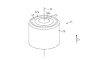
- FIG. 2 is a perspective view of the male connector in the same embodiment.
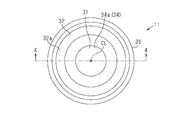
- FIG. 3 is a plan view of the male connector in the same embodiment.
- FIG. 4 is a sectional view taken along line 4-4 in FIG.
- FIG. 5 is an exploded perspective view of the female connector in the same embodiment.
- FIG. 6 is a plan view of the female connector in the same embodiment.
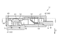
- FIG. 7 is a sectional view taken along line 7-7 in FIG.
- FIG. 8 is a sectional view taken along line 8-8 in FIG.
- FIG. 9 is a cross-sectional view taken along the line 9-9 in FIG.
- FIG. 10 is a cross-sectional view taken along the line 10-10 in FIG.
- FIG. 11 is a cross-sectional view taken along the line 11-11 in FIG.
- FIG. 12 is a cross-sectional view taken along the line 12-12 in FIG.
- FIG. 13 is a cross-sectional view taken along the line 13-13 in FIG.
- FIG. 14 is a cross-sectional view taken along the line 14-14 in FIG.
- FIG. 15 is a cross-sectional view taken along the line 15-15 in FIG.
- FIG. 16 is a cross-sectional view taken along the line 16-16 in FIG.
- FIG. 17 is a cross-sectional view taken along the line 17-17 in FIG.
- the connectors of this disclosure are [1] A connector device having a first connector and a second connector connected to the first connector, wherein the first connector is arranged concentrically with a first positive electrode terminal and the first positive electrode terminal.
- the second negative electrode terminal is arranged concentrically with the second positive electrode terminal connected to the first positive electrode terminal and the second positive electrode terminal, and the first negative electrode terminal is formed. It has a second negative electrode terminal connected to the first connector, and at least one of the first connector and the second connector is urged to give an urging force toward the other side of the first connector and the second connector. It is equipped with a member.
- the first connector and the second connector It is possible to relax the restriction on the orientation of each connector at the time of connection, which can contribute to the improvement of convenience.
- the urging member is elastically deformed in a direction opposite to the urging force by the action of a force resisting the urging force, and the first positive electrode terminal is elastically deformed with the elastic deformation of the urging member.
- Both positive electrode terminals are relatively rotated so that the contact portion between the first negative electrode terminal and the second positive electrode terminal is slid, and the first negative electrode terminal and the second negative electrode terminal are subjected to elastic deformation of the urging member. It is preferable to have a rotation mechanism that relatively rotates both negative electrode terminals so that the abutting portion of the above is slid.
- the contact portion between the first positive electrode terminal and the second positive electrode terminal is rotated by the rotation mechanism so as to slide, and the contact portion between the first negative electrode terminal and the second negative electrode terminal slides. Since it is rotated in this way, rust, dirt, etc. adhering to each terminal can be removed. As a result, it is possible to suppress an increase in electrical resistance at the contact portion between the corresponding terminals.
- the urging member transmits the urging force via a holding portion that holds the positive electrode terminal and the negative electrode terminal to which the urging force is applied together.
- the urging force of the urging member is transmitted through the holding portion that holds the positive electrode terminal and the negative electrode terminal to which the urging force is applied together, one urging member can be used as the positive electrode terminal. It is possible to apply urging force to both the negative electrode terminal and the negative electrode terminal.
- the connector device 10 of the present embodiment electrically connects, for example, an electric vehicle and a battery that can be attached to and detached from the electric vehicle.
- the electric vehicle is, for example, an electric two-wheeled vehicle such as an electric motorcycle or an electric bicycle.
- the connector device 10 has a male connector 11 that is electrically connected to the battery and a female connector 12 that is electrically connected to the electric vehicle.
- the male connector 11 is held by the first housing 20 having the central axis CL extending in the connection direction Z1 between the male connector 11 and the female connector 12, and the first housing 20. It has a plurality of terminals 31 and 32.
- connection direction Z1 is a direction in which the male connector 11 is relatively moved with respect to the female connector 12 when the male connector 11 and the female connector 12 are connected.
- the connection direction Z1 is the same as the direction in which the central axis CL extends.
- the male connector 11 can be arranged in any direction with respect to the vehicle body of the electric vehicle, but in the present embodiment, the male connector 11 is positioned when the male connector 11 and the female connector 12 are connected. This side will be described as an upper side, and the side on which the female connector 12 is located will be described as a lower side.
- the first housing 20 is composed of an insulating resin member.
- the first housing 20 has a cylindrical inner housing 21, a cylindrical intermediate housing 22 located outside the inner housing 21, and a cylindrical outer housing 23 located outside the intermediate housing 22. Further, the first housing 20 accommodates a housing hole 24 for accommodating the first terminal 31 between the inner housing 21 and the intermediate housing 22, and accommodating the first terminal 32 between the intermediate housing 22 and the outer housing 23. It has a hole 25. That is, the accommodating hole 24 is located inside the accommodating hole 25.
- the first terminals 31 and 32 include a first inner terminal 31 and a first outer terminal 32 located on the outer peripheral side of the first inner terminal 31.
- the first terminals 31 and 32 have conductivity and can be made of, for example, metal.
- the first inner terminal 31 has a cylindrical portion 33 and a connection bottom portion 34 that connects one end of the cylindrical portion 33. That is, the first inner terminal 31 has a bottomed cylindrical shape with a cylindrical portion 33 and a connecting bottom portion 34.
- the first inner terminal 31 may be a single metal component that integrally includes a cylindrical portion 33 and a connection bottom portion 34.
- the cylindrical portion 33 is accommodated in the accommodating hole 24 of the first housing 20. At this time, the cylindrical portion 33 covers the outside of the inner housing 21 with its inner peripheral surface in contact with the outer peripheral surface of the inner housing 21. Further, the outer peripheral surface of the cylindrical portion 33 is in contact with the outer peripheral surface of the intermediate housing 22.
- the cylindrical portion 33 is configured such that the central axis of the cylindrical portion 33 passes on the central axis CL in a state of being accommodated in the accommodating hole 24.
- the connection bottom 34 is exposed to the outside from the accommodating hole 24 of the first housing 20.
- the connection bottom 34 has a contact surface 34a that comes into contact with the second terminal 51, which will be described later.
- the contact surface 34a of the connection bottom 34 faces one side in the direction along the central axis CL.
- the first outer terminal 32 is configured to form a cylindrical shape with both ends open.
- the first outer terminal 32 is housed in a housing hole 25 of the first housing 20.
- the first outer terminal 32 covers the outer side of the intermediate housing 22 with its inner peripheral surface in contact with the outer peripheral surface of the intermediate housing 22.
- the outer peripheral surface of the first outer terminal 32 is in contact with the outer peripheral surface of the outer housing 23.
- the first outer terminal 32 is configured such that the central axis of the first outer terminal 32 passes over the central axis CL in a state of being accommodated in the accommodating hole 25. That is, the first outer terminal 32 is opened so as to coincide with the opening direction of the cylindrical portion 33 of the first inner terminal 31 in a state of being accommodated in the accommodating hole 25.
- the first outer terminal 32 has a contact end surface 32a that comes into contact with the second terminal 52, which will be described later, on one side in the direction along the central axis CL.
- the contact end surface 32a of the first outer terminal 32 faces in the direction along the central axis CL in the same direction as the connection bottom 34 of the first inner terminal 31 faces.
- the first inner terminal 31 and the first outer terminal 32 configured as described above are electrically connected to, for example, a battery (not shown).
- One of the first inner terminal 31 and the first outer terminal 32 is the first positive electrode terminal, and the other is the first negative electrode terminal. More specifically, when the positive electrode side of the battery and the first inner terminal 31 are connected, and the negative electrode side of the battery and the first outer terminal 32 are connected, the first inner terminal 31 is the first. It corresponds to the positive electrode terminal, and the first outer terminal 32 corresponds to the first negative electrode terminal. Further, when the positive electrode side of the battery and the first outer terminal 32 are connected and the negative electrode side of the battery and the first inner terminal 31 are connected, the first outer terminal 32 corresponds to the first positive electrode terminal and the first inner terminal. 31 corresponds to the first negative electrode terminal.
- the female connector 12 holds the second housing 40, the second terminals 51 and 52 housed in the second housing 40, and the holding portion 61 for holding the second terminals 51 and 52. It has an urging member 71 that urges the second terminals 51 and 52 via the portion 61.
- the second housing 40 has a housing body 41 and a cover portion 42.
- the housing body 41 has a bottom portion 43 and a peripheral wall portion 44 erected from the peripheral edge portion of the bottom portion 43.
- the housing body 41 is configured such that the bottom portion 43 and the peripheral wall portion 44 form a bottomed tubular shape.
- the second housing 40 has a partition wall portion 45 formed so as to extend from the bottom portion 43 in the same direction as the peripheral wall portion 44.
- the second housing 40 includes a first accommodating portion 46 accommodating the second terminals 51 and 52 by a partition wall portion 45, connecting portions S1 and S2 connecting the electric wires W and the second terminals 51 and 52, and a pair of electric wires. It is partitioned into a second housing section 47 that houses a part of W.
- the second accommodating portion 47 has a partition wall portion 48 that separately accommodates the pair of electric wires W and the connecting portions S1 and S2.
- the first accommodating portion 46 and the second accommodating portion 47 are communicated with each other by communication holes 45a and 45b formed in the partition wall portion 45.
- the cover portion 42 closes a part of the opening 41a opened upward of the housing main body 41.
- the cover portion 42 has a through hole 49 penetrating in the connection direction Z1 (vertical direction), which is a connection path with the first terminals 31 and 32, with the second terminals 51 and 52 housed in the housing body 41.
- the through hole 49 is a circular hole through which the male connector 11 can be inserted.
- the second terminals 51 and 52 have a second inner terminal 51 and a second outer terminal 52. Both the second terminals 51 and 52 are housed in the first housing portion 46 of the housing body 41.
- the second inner terminal 51 has a disc-shaped main body portion 53 and a pull-out portion 54 drawn out from the main body portion 53.
- connection portion S1 is connected to the tip portion of the drawer portion 54.
- the connecting portion S1 has flexibility and conductivity.
- a braided wire can be adopted. Even when the relative position between the second inner terminal 51 and the electric wire W changes, the flexible connecting portion S1 makes it possible to follow the change according to the change.
- the core wire W1 of the electric wire W is connected to the end of the connecting portion S1 on the opposite side of the lead-out portion 54 via the relay terminal 55.
- the second outer terminal 52 has an arc plate-shaped main body portion 57 and a pull-out portion 58 drawn out from an end portion of the main body portion 57.
- connection portion S2 is connected to the tip portion of the drawer portion 58.
- the connecting portion S2 has flexibility and conductivity.
- a braided wire can be adopted. Even when the relative position between the second outer terminal 52 and the electric wire W changes, the flexible connecting portion S2 makes it possible to follow the change according to the change.
- the core wire W1 of the electric wire W is connected to the end of the connecting portion S2 on the opposite side of the lead-out portion 58 via the relay terminal 59.
- One of the second inner terminal 51 and the second outer terminal 52 configured as described above is the second positive electrode terminal, and the other is the second negative electrode terminal.
- the second inner terminal 51 is the second. It is a positive electrode terminal
- the second outer terminal 52 is a second negative electrode terminal.
- the second outer terminal 52 is the second. It is a positive electrode terminal
- the second inner terminal 51 is a second negative electrode terminal.
- the holding portion 61 has a disc-shaped holding main body portion 62 and a supporting portion 63 that movably supports the holding main body portion 62 with respect to the housing main body 41.
- the holding body portion 62 has an inner holding groove portion 64 for holding the second inner terminal 51 and an outer holding groove portion 65 for holding the second outer terminal 52. Since the holding main body portion 62 is larger than the through hole 49 of the cover portion 42, it is prevented from falling out of the through hole 49.
- the inner holding groove portion 64 has a groove shape for accommodating the second inner terminal 51. That is, the inner holding groove portion 64 has a groove shape that follows the shape of the disc-shaped main body portion 53 and the drawer portion 54 of the second inner terminal 51.
- the outer holding groove portion 65 has a groove shape for accommodating the second outer terminal 52. That is, the outer holding groove portion 65 has a groove shape that follows the shape of the arc plate-shaped main body portion 57 and the drawer portion 58 of the second outer terminal 52.
- the support portion 63 is configured to extend outward from the end surface on the outer peripheral side of the holding main body portion 62.
- a total of two support portions 63 are provided at equal intervals of about 180 ° in the circumferential direction with respect to the holding main body portion 62.
- the support portion 63 is fitted into the support groove portion 44a formed in the peripheral wall portion 44 of the housing main body 41 in a state where the holding portion 61 is housed in the housing main body 41, and is movable along the support groove portion 44a. ..
- the support groove portion 44a is formed along the connection direction Z1 (vertical direction). That is, the holding portion 61 can be moved up and down along the connection direction Z1 by the support portion 63 and the support groove portion 44a.
- the urging member 71 is interposed between the bottom portion 43 of the housing body 41 and the holding portion 61.
- a compression coil spring can be adopted for the urging member 71.
- the urging member 71 urges the second terminals 51 and 52, which are the objects to which the urging force is applied, via the holding portion 61. Therefore, when the male connector 11 and the female connector 12 are not connected, the holding portion 61 and the second terminals 51 and 52 are located in the vicinity of the through hole 49 of the cover portion 42 by the urging member 71.
- the female connector 12 has a rotation mechanism 80 that relatively rotates the second inner terminal 51 and the second outer terminal 52 when connected to the male connector 11.
- the rotation mechanism 80 the contact portion between the first inner terminal 31 and the second inner terminal 51 is slid with the elastic deformation of the urging member 71, and the first outer terminal is slid with the elastic deformation of the urging member 71.
- the corresponding terminals are relatively rotated so that the contact portion between the 32 and the second outer terminal 52 is slid.
- the rotation mechanism 80 has communication holes 45a and 45b of the partition wall portion 45 and a holding portion 61.
- the communication holes 45a and 45b are inclined with respect to the connection direction Z1. More specifically, the connection direction Z1 so that the lower end side of the communication hole 45a and the lower end side of the communication hole 45b are relatively close to each other, and the upper end side of the communication hole 45a and the upper end side of the communication hole 45b are relatively separated. It is inclined with respect to. Therefore, if the second inner terminal 51 is moved up and down with the drawer portion 54 of the second inner terminal 51 fitted into the communication hole 45a, the second inner terminal 51 is moved along the communication hole 45a. As a result, the second inner terminal 51 rotates.
- the rotation mechanism 80 converts linear motion into rotary motion.
- the rotation directions of the second inner terminal 51 and the second outer terminal 52 are opposite to each other.
- the urging member is formed by the first terminals 31 and 32 of the male connector 11.
- a force that opposes the urging force of 71 acts to deform the urging member 71 in the compression direction.
- the holding portion 61 moves in the compression direction (the same direction as the connection direction Z1) of the urging member 71.
- the second terminals 51 and 52 held by the holding portion 61 also move in the compression direction of the urging member 71.
- the second inner terminal 51 and the second outer terminal 52 move along the inclined communication holes 45a and 45b, respectively, and the second inner terminal 51 And the second outer terminal 52 are close to the bottom 43 of the housing body 41. That is, although the holding portion 61 is a simple vertical movement, the second inner terminal 51 and the second outer terminal 52 held by the holding portion 61 are in a direction in which at least the drawing portions 54 and 58 are inclined with respect to the connection direction Z1. Will move to.
- the second inner terminal 51 and the second outer terminal 52 held by the holding portion 61 rotate in the inner holding groove portion 64 and the outer holding groove portion 65 of the holding portion 61.
- the contact end surface 32a of the first outer terminal 32 and the main body 57 of the second outer terminal 52 are in contact with each other, and the contact surface 34a of the connection bottom 34 of the first inner terminal 31 and the second inner side are in contact with each other.
- the terminal 51 is in contact with the main body 53, and the contact portion is rotated so as to slide.
- the first inner terminal 31 and the first outer terminal 32 of the male connector 11 are arranged concentrically with the second inner terminal 51 and the second outer terminal 52 of the female connector 12. Are arranged concentrically.
- the rotation mechanism 80 rotates the contact portion between the first inner terminal 31 and the second inner terminal 51 so as to slide, and the contact portion between the first outer terminal 32 and the second outer terminal 52 slides. Since it is rotated so as to move, rust, dirt, and the like adhering to the terminals 31, 32, 51, and 52 can be removed. As a result, it is possible to suppress an increase in electrical resistance between the contact portions of the terminals 31 and 32 and the contact portions of the negative electrode terminals 51 and 52. Further, since the rotation directions of the second inner terminal 51 and the second outer terminal 52 are opposite to each other, the torque associated with the rotation can be offset.
- the urging force of the urging member 71 is transmitted through the holding portion 61 that holds the second inner terminal 51 and the second outer terminal 52 to be urged together, one urging force is applied.
- the member 71 can apply an urging force to both the second inner terminal 51 and the second outer terminal 52.
- the urging force of the urging member 71 is applied to the second inner terminal 51 and the second outer terminal 52 via one holding portion 61, but the present invention is not limited to this.
- a configuration may be adopted in which a holding portion for holding the second inner terminal 51 and a holding portion for holding the second outer terminal 52 are provided, and urging force is applied to each holding portion from one urging member.
- a structure is adopted in which a holding portion for holding the second inner terminal 51 and a holding portion for holding the second outer terminal 52 are provided, and an urging force is applied to each holding portion from an individually corresponding urging member. You may.
- the configuration having the holding portion 61 is adopted, but a configuration in which the holding portion is omitted may be adopted.
- the urging member 71 is provided on the female connector 12 side, but the present invention is not limited to this.
- a configuration may be adopted in which an urging member is further provided on the male connector 11 side.
- a configuration in which the urging member is provided only on the male connector 11 side may be adopted.
- the female connector 12 is provided with the rotation mechanism 80, but an omitted configuration may be adopted.
- the communication holes 45a and 45b can be formed along the vertical direction so that the rotation mechanism can be substantially omitted.
- the compression coil spring is used as the urging member 71, but the present invention is not limited to this, and other urging members such as a tension coil spring and a leaf spring may be adopted.
- the present invention is not limited to this.
- a configuration may be adopted in which the terminals 51 and 52 of the female connector 12 are connected to the electric motor without using an inverter. In this case, it does not matter whether the vehicle is equipped with an inverter.
- the female connector 12 is on the vehicle side and the male connector 11 is on the battery side, but these relationships may be reversed. That is, the female connector may be on the battery side and the male connector may be on the vehicle side.
- the female connector 12 is fixed to the vehicle body.
- the female connector 12 is indirectly fixed to the vehicle body via the device by being fixed to or mounted on a device such as an inverter. May be good.
- the connector device 10 is used for electrically connecting an electric vehicle, which is an electric motorcycle, and a battery, for example.
- the electric vehicle that is electrically connected to the battery by the connector device 10 is not limited to this.
- the electric vehicle may be, for example, an electric tricycle, an electric four-wheeled vehicle, or the like.
- an agricultural vehicle represented by an electric cultivator driven by a replaceable battery can be adopted.
- connection portions S1, S2, the second inner terminal 51 and the second outer terminal 52 may be on the same plane orthogonal to the connection direction Z1. According to this, the height of the accommodation space of the second housing 40 in the connection direction Z1 can be reduced.
- connection direction Z1 When the first connector and the second connector are linearly connected in the connection direction Z1, the plurality of terminals of the first connector and the plurality of terminals having the corresponding polaritys of the second connector are in surface contact in the connection direction Z1. , And may be configured to slide contact in a plane intersecting or orthogonal to the connection direction Z1.
- the central axis CL of the male connector 11 may pass through the centers of the first terminals 31 and 32 arranged concentrically. And / or may pass through the center of the second terminals 51, 52 arranged concentrically and / or coincide with the coil shaft of the coil spring as the urging member 71.
- the urging member 71 may be a coil spring having a coil axis that coincides with the connection direction Z1 or the central axis CL.
- the holding portion 61 and the housing body 41 may be configured to support or position both ends of the coil spring as the urging member 71 so that both ends of the coil spring do not shift in the radial direction of the coil spring.
- the holding portion 61 may have a first coil end positioning step that supports or positions the moving end or the tip winding portion of the coil spring that can move in the connection direction Z1, and the housing body 41 may have a connection direction Z1.
- the first coil end positioning step of the holding portion 61 may be configured as a first convex portion that may be a downward convex portion that supports the tip winding portion of the coil spring from the inside in the radial direction.
- the second coil end positioning step of the housing body 41 is a second convex portion that can be an upward convex portion facing the first convex portion that supports the base end winding portion of the coil spring from the inside in the radial direction. And / or may be configured as an annular groove that sandwiches the base end winding portion of the coil spring from the inside in the radial direction and the outside in the radial direction.
- the tip of the first convex portion of the holding portion 61 (the lower end of the downward convex portion) and the tip of the second convex portion of the housing body 41 (the upper end of the upward convex portion). May be in contact.
- the tip of the first convex portion of the holding portion 61 and the tip of the second convex portion of the housing body 41 may be a flat surface.
- the first and second coil end positioning steps (first and second convex portions) of the holding portion 61 and the housing body 41 support the coil spring as the biasing member 71 from the inside in the radial direction, so that the coil spring is connected.
- a connector device (10) may include a first connector (11) and a second connector (12).
- the first connector (11) can be configured to be electrically and mechanically connected to the second connector (12) by moving relative to the second connector (12) in the linear connection direction (Z1).
- the first connector (11) can include a plurality of first connector terminals (31, 32).
- the second connector (12) can include a plurality of second connector terminals (51, 52).
- the plurality of first connector terminals (31, 32) have a first connector end face that intersects or is orthogonal to the linear connection direction (Z1) and a first polarity that is one of a positive electrode and a negative electrode, and the first connector.
- It can include a first electrode surface (34a) provided on the end face and a second electrode surface (32a) having a second polarity which is the other of the positive electrode and the negative electrode and provided on the end face of the first connector.
- the plurality of second connector terminals (51, 52) have a second connector end face that intersects or is orthogonal to the linear connection direction (Z1), and a first that has the first polarity and is provided on the second connector end face.
- An electrode surface (53) and a second electrode surface (57) having the second polarity and provided on the end surface of the second connector can be included.
- the first electrode surface (34a) and the second electrode surface (32a) of the plurality of first connector terminals (31, 32) can be arranged concentrically on the end surface of the first connector.
- the first electrode surface (53) and the second electrode surface (57) of the plurality of second connector terminals (51, 52) can be arranged concentrically on the end surface of the second connector.
- the second electrode surface (57) can be configured to be linearly displaced by a predetermined distance in the linear connection direction (Z1).
- the second connector (12) is Insulation that accommodates the elastic element (71) that elastically supports the plurality of second connector terminals (51, 52), and the plurality of second connector terminals (51, 52) and the elastic element (71).
- the elastic element (71) has the first electrode surface (53) and the second electrode surface (57) of the plurality of second connector terminals (51, 52) in the insulating housing (40). It can be configured to allow linear elastic displacement by the predetermined distance in the linear connection direction (Z1).
- the second connector (12) has the second connector end faces of the plurality of second connector terminals (51, 52) and the plurality of first connector terminals (31, 32).
- a rotation mechanism (80) for rotating the first connector end face by a predetermined rotation angle around the linear connection direction (Z1) can be included.
- the rotation mechanism (80) is When connecting and disconnecting the first connector (11) and the second connector (12), the second connector end faces of the plurality of second connector terminals (51, 52) are insulated. Circumferential direction around the linear connection direction (Z1) in the insulating housing (40) so as to be linearly displaced by the predetermined distance in the linear connection direction (Z1) in the property housing (40). It can be configured to guide the displacement of the plurality of second connector terminals (51, 52) so as to rotate by the predetermined rotation angle.
- the plurality of first connector terminals (31, 32) when connecting and disconnecting the first connector (11) and the second connector (12), the plurality of first connector terminals (31, 32) are connected.
- the plurality of first connector terminals (31, 32) in a state where the first electrode surface (34a) and the first electrode surface (53) of the plurality of second connector terminals (51, 52) are in direct contact with each other.
- the first electrode surface (34a) of the above and the first electrode surface (53) of the plurality of second connector terminals (51, 52) are relative to each other by a predetermined rotation angle around the linear connection direction (Z1). It can be configured to rotate.
- the plurality of first connector terminals (31, 32) when connecting and disconnecting the first connector (11) and the second connector (12), the plurality of first connector terminals (31, 32) are connected.
- the plurality of first connector terminals (31, 32) in a state where the second electrode surface (32a) and the second electrode surface (57) of the plurality of second connector terminals (51, 52) are in direct contact with each other.
- the second electrode surface (32a) of the above and the second electrode surface (57) of the plurality of second connector terminals (51, 52) are relative to each other by a predetermined rotation angle around the linear connection direction (Z1). It can be configured to rotate.
- the first electrode surface (34a) and the second electrode surface (32a) of the plurality of first connector terminals (31, 32) are radial inner electrode surfaces (34a). And can be arranged on the first connector end face as the radial outer electrode surface (32a), respectively.
- the first electrode surface (53) and the second electrode surface (57) of the plurality of second connector terminals (51, 52) are designated as a radial inner electrode surface (53) and a radial outer electrode surface (57). It can be arranged on each of the end faces of the second connector.
- the first electrode surface (34a) and the second electrode surface (32a) of the plurality of first connector terminals (31, 32) are formed as a circular surface and an annular surface, respectively.
- the first electrode surface (53) and the second electrode surface (57) of the plurality of second connector terminals (51, 52) can be configured as a circular surface and an annular surface, respectively.
- the first electrode surface (34a) of the plurality of first connector terminals (31, 32) and the first electrode surface of the plurality of second connector terminals (51, 52). (53) can have a common central axis (CL) and a common first outer diameter.
- the second electrode surface (32a) of the plurality of first connector terminals (31, 32) and the second electrode surface (57) of the plurality of second connector terminals (51, 52) have a common central axis. (CL) and a common second outer diameter can be provided.
- the plurality of first connector terminals (31, 32) are concentric with the first cylindrical electrode (31) having two open ends and the first cylindrical electrode (31).
- the first connector (11) is arranged between the outer peripheral surface of the first cylindrical electrode (31) and the inner peripheral surface of the second cylindrical electrode (32).
- a tubular insulating synthetic resin layer (22) that insulates the first cylindrical electrode (31) and the second cylindrical electrode (32) can be included.
- the first connector (11) is a circle in which the first cylindrical electrode (31), the second cylindrical electrode (32), and the tubular insulating synthetic resin layer (22) are integrally or non-movably provided. It may be configured as a columnar monolithic block.
- the plurality of first connector terminals (31, 32) may be non-spring-like metal terminals.
- the first electrode surface (53) and the second electrode surface (57) of the plurality of second connector terminals (51, 52) may be flat surfaces.
- each of the plurality of second connector terminals (51, 52) may be a metal plate.
- the connector device (10) can be configured to connect an electric wire (W) having a positive electrode and a negative electrode to a DC electric device.
- Connector device 11 Male connector (first connector) 12 Female connector (second connector) 20 1st housing 21 Inner housing 22 Intermediate housing 23 Outer housing 24 Housing hole 25 Housing hole 31 1st inner terminal 32 1st outer terminal 32a Contact end face 33 Cylindrical part 34 Connection bottom 34a Contact surface 40 Second housing 41 Housing body 41a Opening 42 Cover 43 Bottom 44 Peripheral wall 44a Support groove 45 Partition wall 45a Communication hole 45b Communication hole 46 1st housing 47 2nd housing 48 Partition 49 Through hole 51 2nd inner terminal 52 2nd outer terminal 53 Main body 54 Drawer 55 Relay terminal 57 Main body 58 Drawer 59 Relay terminal 61 Holding 62 Holding main body 63 Support 64 Inner holding groove 65 Outer holding groove 71 Biasing member 80 Rotation mechanism CL Center axis S1 Connection S2 Connection part W Electric wire W1 Core wire Z1 Connection direction
Landscapes
- Details Of Connecting Devices For Male And Female Coupling (AREA)
- Coupling Device And Connection With Printed Circuit (AREA)
Abstract
利便性を向上できるコネクタ装置を提供する。 オスコネクタ(11)は、第1内側端子(31)と、第1内側端子(31)と同心円状に配置される第1外側端子(32)とを有する。メスコネクタ'(12)は、第1内側端子(31)と接続される第2内側端子(51)と、第2内側端子(51)と同心円状に配置されるとともに第1外側端子(32)と接続される第2外側端子(52)とを有する。オスコネクタ(11)とメスコネクタ(12)の少なくとも一方には、オスコネクタ(11)とメスコネクタ(12)の他方側に向けて付勢力を付与する付勢部材(71)を備える。
Description
本発明は、コネクタ装置に関する。
自動車や電動バイク等においてバッテリとインバータとを接続するために用いられるコネクタ装置は、複数の第1端子を有する第1コネクタと、複数の第1端子に電気的に接続される複数の第2端子を有する第2コネクタとを備えている(例えば、特許文献1参照)。第1コネクタ及び第2コネクタの何れか一方のコネクタがインバータと電気的に接続されるとともに、何れか他方のコネクタがバッテリと電気的に接続される。そして、第1コネクタと第2コネクタとが接続されることにより、第1端子と第2端子とが電気的に接続されて、コネクタ装置を介してバッテリとインバータとが電気的に接続されることになる。
ところで、電動車両(インバータ)とバッテリとを電気的に接続する場合、第1コネクタの端子と第2コネクタの端子とを接続する必要がある。このとき、第1端子を構成する正極端子及び負極端子と、第2端子を構成する正極端子及び負極端子とは、どちらも第1コネクタと第2コネクタの接続方向と直交する方向に並列に設けられているため、第1コネクタと第2コネクタとの接続の向きに制限が生じるため、利便性の面で向上の余地がある。
本発明は、上記課題を解決するためになされたものであって、その目的は、利便性を向上できるコネクタ装置を提供することにある。
本開示のコネクタ装置は、第1コネクタと、該第1コネクタと接続される第2コネクタとを有するコネクタ装置であって、前記第1コネクタは、第1正極端子と、該第1正極端子と同心円状に配置される第1負極端子とを有し、前記第2コネクタは、前記第1正極端子と接続される第2正極端子と、該第2正極端子と同心円状に配置されるとともに前記第1負極端子と接続される第2負極端子とを有し、前記第1コネクタと前記第2コネクタの少なくとも一方には、前記第1コネクタと前記第2コネクタの他方側に向けて付勢力を付与する付勢部材を備える。
本発明のコネクタ装置によれば、利便性を向上できる。
[本開示の実施形態の説明]
最初に本開示の実施形態を列記して説明する。
最初に本開示の実施形態を列記して説明する。
本開示のコネクタは、
[1]第1コネクタと、該第1コネクタと接続される第2コネクタとを有するコネクタ装置であって、前記第1コネクタは、第1正極端子と、該第1正極端子と同心円状に配置される第1負極端子とを有し、前記第2コネクタは、前記第1正極端子と接続される第2正極端子と、該第2正極端子と同心円状に配置されるとともに前記第1負極端子と接続される第2負極端子とを有し、前記第1コネクタと前記第2コネクタの少なくとも一方には、前記第1コネクタと前記第2コネクタの他方側に向けて付勢力を付与する付勢部材を備える。
[1]第1コネクタと、該第1コネクタと接続される第2コネクタとを有するコネクタ装置であって、前記第1コネクタは、第1正極端子と、該第1正極端子と同心円状に配置される第1負極端子とを有し、前記第2コネクタは、前記第1正極端子と接続される第2正極端子と、該第2正極端子と同心円状に配置されるとともに前記第1負極端子と接続される第2負極端子とを有し、前記第1コネクタと前記第2コネクタの少なくとも一方には、前記第1コネクタと前記第2コネクタの他方側に向けて付勢力を付与する付勢部材を備える。
上記態様によれば、第1正極端子と第1負極端子とが同心円状に配置され、第2正極端子と第2負極端子とが同心円状に配置されるため、第1コネクタと第2コネクタとの接続時における各コネクタの向きの制限を緩和することができ、利便性向上に寄与できる。
[2]前記付勢部材は、付勢力に抗する力が作用することで前記付勢力と反対方向に弾性変形するものであって、前記付勢部材の弾性変形に伴って前記第1正極端子と前記第2正極端子との当接部分が摺動されるように両正極端子を相対的に回転させ、前記付勢部材の弾性変形に伴って前記第1負極端子と前記第2負極端子との当接部分が摺動されるように両負極端子を相対的に回転させる回転機構を有することが好ましい。
この態様によれば、回転機構により第1正極端子と第2正極端子との当接部分が摺動するように回転され、第1負極端子と第2負極端子との当接部分が摺動するように回転されるため、各端子に付着した錆や汚れ等を除去することができる。これにより、対応する端子同士の当接部分の電気抵の増大を抑えることができる。
[3]前記付勢部材は、付勢力を付与する対象の前記正極端子と前記負極端子とを合わせて保持する保持部を介して前記付勢力を伝達することが好ましい。
この態様によれば、付勢力を付与する対象の正極端子と負極端子とを合わせて保持する保持部を介して付勢部材の付勢力が伝達されるため、1つの付勢部材によって正極端子と負極端子との両方に付勢力を付与することができる。
[本開示の実施形態の詳細]
以下、コネクタの具体例を、以下に図面を参照しつつ説明する。なお、本発明はこれらの例示に限定されるものではなく、特許請求の範囲によって示され、特許請求の範囲と均等の意味及び範囲内でのすべての変更が含まれることが意図される。
以下、コネクタの具体例を、以下に図面を参照しつつ説明する。なお、本発明はこれらの例示に限定されるものではなく、特許請求の範囲によって示され、特許請求の範囲と均等の意味及び範囲内でのすべての変更が含まれることが意図される。
図1に示すように、本実施形態のコネクタ装置10は、例えば、電動車両と同電動車両に着脱可能なバッテリとを電気的に接続するものである。電動車両は、例えば、電動バイクや電動自転車等の電動二輪車である。コネクタ装置10は、バッテリに電気的に接続されるオスコネクタ11と、電動車両に電気的に接続されるメスコネクタ12とを有する。
図2、図3及び図4に示すようにオスコネクタ11は、オスコネクタ11とメスコネクタ12との接続方向Z1に伸びる中心軸線CLを有する第1ハウジング20と、第1ハウジング20に保持された複数の端子31,32とを有する。
ここで、接続方向Z1は、オスコネクタ11とメスコネクタ12とを接続する際に、メスコネクタ12に対してオスコネクタ11が相対的に移動される方向である。接続方向Z1は中心軸線CLの延びる方向と同じである。オスコネクタ11は、電動車両の車両ボディに対して任意の向きで配置することが可能であるが、本実施形態ではオスコネクタ11とメスコネクタ12とが接続された状態において、オスコネクタ11が位置する側を上方、メスコネクタ12が位置する側を下方として説明する。
図4に示すように、第1ハウジング20は、絶縁樹脂部材で構成される。第1ハウジング20は、円柱状の内側ハウジング21と、内側ハウジング21の外側に位置する円筒状の中間ハウジング22と、中間ハウジング22の外側に位置する円筒状の外側ハウジング23とを有する。また、第1ハウジング20は、内側ハウジング21と中間ハウジング22との間に第1端子31を収容する収容孔24と、中間ハウジング22と外側ハウジング23との間に第1端子32を収容する収容孔25とを有する。すなわち、収容孔24は、収容孔25よりも内側に位置する。
図4に示すように、第1端子31,32は、第1内側端子31と、第1内側端子31の外周側に位置する第1外側端子32とを含む。第1端子31,32は導電性を有し、例えば金属で構成することができる。
第1内側端子31は、円筒部33と円筒部33の一方の端部を接続する接続底部34とを有する。すなわち、第1内側端子31は円筒部33と接続底部34とで有底筒状をなしている。例えば、第1内側端子31は、円筒部33と接続底部34とを一体に含む金属単一部品であってよい。円筒部33は、第1ハウジング20の収容孔24に収容されている。このとき円筒部33は、自身の内周面が内側ハウジング21の外周面と当接した状態で内側ハウジング21の外側を覆っている。また、円筒部33は、自身の外周面が中間ハウジング22の外周面と当接している。円筒部33は、収容孔24に収容された状態で中心軸線CL上を円筒部33の中心軸線が通るように構成される。接続底部34は、第1ハウジング20の収容孔24から外部に露出している。接続底部34は、後述する第2端子51と当接する当接面34aを有する。接続底部34の当接面34aは、中心軸線CLに沿った方向における一方側に面している。
第1外側端子32は、両端が開口された円筒状をなすように構成される。第1外側端子32は、第1ハウジング20の収容孔25に収容されている。このとき第1外側端子32は、自身の内周面が中間ハウジング22の外周面と当接した状態で中間ハウジング22の外側を覆っている。また、第1外側端子32は、自身の外周面が外側ハウジング23の外周面と当接している。第1外側端子32は、収容孔25に収容された状態で前記中心軸線CL上を第1外側端子32の中心軸線が通るように構成される。すなわち、第1外側端子32は、収容孔25に収容された状態で第1内側端子31の円筒部33の開口方向と一致するように開口している。第1外側端子32は、中心軸線CLに沿った方向における一方側に後述する第2端子52と当接する当接端面32aを有する。第1外側端子32の当接端面32aは、中心軸線CLに沿った方向において第1内側端子31の接続底部34が面する方向と同方向に面している。
上記のように構成された第1内側端子31及び第1外側端子32は、例えば図示しないバッテリに電気的に接続される。第1内側端子31及び第1外側端子32は、いずれか一方が第1正極端子であり、いずれか他方が第1負極端子である。より具体的には、より具体的には、バッテリの正極側と第1内側端子31が接続され、バッテリの負極側と第1外側端子32が接続された場合、第1内側端子31が第1正極端子に相当し、第1外側端子32が第1負極端子に相当する。また、バッテリの正極側と第1外側端子32が接続され、バッテリの負極側と第1内側端子31が接続された場合、第1外側端子32が第1正極端子に相当し、第1内側端子31が第1負極端子に相当する。
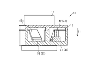
図5に示すように、メスコネクタ12は、第2ハウジング40と、第2ハウジング40内に収容される第2端子51,52と、第2端子51,52を保持する保持部61と、保持部61を介して第2端子51,52を付勢する付勢部材71とを有する。
第2ハウジング40は、ハウジング本体41と、カバー部42とを有する。
ハウジング本体41は、底部43と底部43の周縁部から立設された周壁部44とを有する。ハウジング本体41は、底部43と周壁部44とで有底筒状をなすように構成される。第2ハウジング40は、底部43から周壁部44と同方向に延びる態様で形成された仕切り壁部45を有する。第2ハウジング40は、仕切り壁部45により、第2端子51,52を収容する第1収容部46と、電線Wと第2端子51,52とを接続する接続部S1,S2及び一対の電線Wの一部を収容する第2収容部47とに仕切られる。第2収容部47は、一対の電線W及び接続部S1,S2をそれぞれ個別に収容可能に隔てる隔壁部48を有する。第1収容部46と第2収容部47とは、仕切り壁部45に形成された連通孔45a,45bにより連通される。
カバー部42は、ハウジング本体41の上方向に向けて開口された開口部41aの一部を閉塞するものである。カバー部42は、第2端子51,52をハウジング本体41に収容した状態で第1端子31,32との接続経路である接続方向Z1(上下方向)に貫通する貫通孔49を有する。貫通孔49は、円形状の孔であってオスコネクタ11を挿通可能となっている。
第2端子51,52は、第2内側端子51と第2外側端子52とを有する。第2端子51,52は、いずれもハウジング本体41の第1収容部46に収容される。
第2内側端子51は、円板状の本体部53と、本体部53から引き出された引き出し部54とを有する。
引き出し部54の先端部には、接続部S1が接続される。接続部S1は、可撓性及び導電性を有する。接続部S1の一例として、例えば編組線を採用することができる。第2内側端子51と電線Wとの相対位置が変化した場合であっても、可撓性を有する接続部S1によってその変化に応じて追従することが可能となる。接続部S1の前記引き出し部54とは反対側の端部には、中継端子55を介して電線Wの芯線W1が接続されている。
第2外側端子52は、円弧板状の本体部57と、本体部57の端部から引き出された引き出し部58とを有する。
引き出し部58の先端部には、接続部S2が接続される。接続部S2は、可撓性及び導電性を有する。接続部S2の一例として、例えば編組線を採用することができる。第2外側端子52と電線Wとの相対位置が変化した場合であっても、可撓性を有する接続部S2によってその変化に応じて追従することが可能となる。接続部S2の前記引き出し部58とは反対側の端部には、中継端子59を介して電線Wの芯線W1が接続されている。
上記のように構成された第2内側端子51及び第2外側端子52は、いずれか一方が第2正極端子であり、いずれか他方が第2負極端子である。例えば、インバータの正極側と電線Wを介して第2内側端子51が接続され、インバータの負極側と電線Wを介して第2外側端子52が接続された場合、第2内側端子51は第2正極端子であり、第2外側端子52は第2負極端子である。また、インバータの正極側と電線Wを介して第2外側端子52が接続され、インバータの負極側と電線Wを介して第2内側端子51が接続された場合、第2外側端子52は第2正極端子であり、第2内側端子51が第2負極端子である。
図5に示すように、保持部61は、円板状の保持本体部62と、保持本体部62をハウジング本体41に対して移動可能に支持する支持部63とを有する。
保持本体部62は、第2内側端子51を保持する内側保持溝部64と、第2外側端子52を保持する外側保持溝部65とを有する。保持本体部62は、カバー部42の貫通孔49よりも大きいため、貫通孔49からの脱落することが抑えられている。
内側保持溝部64は、第2内側端子51を収容する溝形状である。すなわち、内側保持溝部64は、第2内側端子51の円板状の本体部53と引き出し部54との形状に倣った溝形状となっている。
外側保持溝部65は、第2外側端子52を収容する溝形状である。すなわち、外側保持溝部65は、第2外側端子52の円弧板状の本体部57と引き出し部58との形状に倣った溝形状となっている。
支持部63は、保持本体部62の外周側の端面から外側に延出するように構成される。支持部63は、保持本体部62に対して周方向略180°等間隔で計2つ設けられる。支持部63は、保持部61をハウジング本体41に対して収容した状態で、ハウジング本体41の周壁部44に形成された支持溝部44aに嵌入され、同支持溝部44aに沿って移動可能とされる。このとき、支持溝部44aは、接続方向Z1(上下方向)に沿って形成される。すなわち、保持部61は、支持部63並びに支持溝部44aによって接続方向Z1に沿って上下動可能となっている。
図5に示すように、付勢部材71は、ハウジング本体41の底部43と、保持部61との間に介在されている。付勢部材71は、例えば圧縮コイルバネを採用することができる。
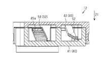
図6~図8に示すように、付勢部材71は、保持部61を介して付勢力を付与する対象である第2端子51,52を上方側に付勢している。このため、オスコネクタ11とメスコネクタ12とが接続されていない場合に、付勢部材71により保持部61並びに第2端子51,52がカバー部42の貫通孔49近傍に位置している。
図9~図11に示すように、メスコネクタ12は、第2内側端子51及び第2外側端子52をオスコネクタ11との接続時において相対的に回転させる回転機構80を有する。回転機構80は、付勢部材71の弾性変形に伴って第1内側端子31と第2内側端子51との当接部分が摺動され、付勢部材71の弾性変形に伴って第1外側端子32と第2外側端子52との当接部分が摺動されるように対応する端子同士を相対的に回転させるものである。
図9~図11に示すように、回転機構80は、仕切り壁部45の連通孔45a,45bと、保持部61とを有する。
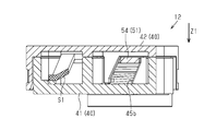
図10及び図11に示すように、連通孔45a,45bは、接続方向Z1に対して傾斜している。より具体的には、連通孔45aの下端側と連通孔45bの下端側とは相対的に近づき、連通孔45aの上端側と連通孔45bの上端側とは相対的に離れるように接続方向Z1に対して傾斜している。このため、連通孔45aに対して第2内側端子51の引き出し部54が嵌入された状態で、第2内側端子51が上下動されると、連通孔45aに沿って移動されることとなる。その結果、第2内側端子51が回転する。また、連通孔45bに対して第2外側端子52の引き出し部58が嵌入された状態で、第2外側端子52が上下動されると、連通孔45bに沿って移動されることとなる。その結果、第2外側端子52の本体部57が外側保持溝部65に沿って回転する。すなわち、回転機構80は、直線運動を回転運動に変換するものである。本実施形態の回転機構80では、連通孔45a,45bに沿った回転となるため、第2内側端子51と第2外側端子52との回転方向は逆向きとなっている。
本実施形態の作用を説明する。
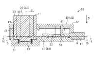
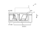
図12及び図13に示すように、上記のように構成されたオスコネクタ11をメスコネクタ12に対して接続方向Z1に移動させることで、オスコネクタ11の第1端子31,32により付勢部材71の付勢力に抗する力が作用して、付勢部材71が圧縮方向に変形する。付勢部材71が圧縮方向に変形すると、保持部61が付勢部材71の圧縮方向(接続方向Z1と同方向)に移動する。これに伴い、保持部61によって保持されている第2端子51,52も付勢部材71の圧縮方向に移動する。
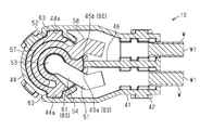
図16及び図17に示すように、第2内側端子51と第2外側端子52とは、それぞれの引き出し部54,58が傾斜した連通孔45a,45bに沿って移動し、第2内側端子51と第2外側端子52とがハウジング本体41の底部43と近接する。つまり、保持部61は単純な上下動であるが、保持部61に保持された第2内側端子51と第2外側端子52とは少なくとも引き出し部54,58が接続方向Z1に対して傾斜した方向に移動することとなる。
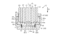
図14及び図15に示すように、保持部61に保持された第2内側端子51と第2外側端子52とは、保持部61の内側保持溝部64と外側保持溝部65内で回転することとなる。このとき、第1外側端子32の当接端面32aと第2外側端子52の本体部57とが当接した状態であり、第1内側端子31の接続底部34の当接面34aと第2内側端子51の本体部53とが当接した状態であり、当接部分が摺動するように回転されることとなる。
また、本実施形態のコネクタ装置10は、オスコネクタ11の第1内側端子31と第1外側端子32とが同心円状に配置され、メスコネクタ12の第2内側端子51と第2外側端子52とが同心円状に配置される。
本実施形態の効果を記載する。
(1)オスコネクタ11とメスコネクタ12との接続時における各コネクタ11,12の向きの制限を緩和することができ、利便性向上に寄与できる。また、メスコネクタ12の第2端子51,52は付勢部材71によりオスコネクタ11の第1端子31,32側に付勢されているため、接続信頼性を確保でき、確実な接続状態を維持することが可能となる。
(2)回転機構80により第1内側端子31と第2内側端子51との当接部分が摺動するように回転され、第1外側端子32と第2外側端子52との当接部分が摺動するように回転されるため、各端子31,32,51,52に付着した錆や汚れ等を除去することができる。これにより、端子31,32の当接部分及び負極の端子51,52の当接部分の電気抵抗の増大を抑えることができる。また、第2内側端子51と第2外側端子52との回転方向が逆向きであるため、回転に伴うトルクを相殺することができる。
(3)付勢力を付与する対象の第2内側端子51と第2外側端子52とを合わせて保持する保持部61を介して付勢部材71の付勢力が伝達されるため、1つの付勢部材71によって第2内側端子51と第2外側端子52との両方に付勢力を付与することができる。
なお、上記実施形態は、以下のように変更して実施することができる。上記実施形態及び以下の変更例は、技術的に矛盾しない範囲で互いに組み合わせて実施することができる。
上記実施形態では、1つの保持部61を介して付勢部材71の付勢力を第2内側端子51と第2外側端子52に対して付与する構成を採用したが、これに限らない。第2内側端子51を保持する保持部と第2外側端子52を保持する保持部を有し、各保持部を1つの付勢部材から付勢力が付与される構成を採用してもよい。また、第2内側端子51を保持する保持部と第2外側端子52を保持する保持部とを有し、各保持部に個別に対応する付勢部材から付勢力が付与される構成を採用してもよい。
・上記実施形態では、保持部61を有する構成を採用したが、保持部を省略した構成を採用してもよい。
・上記実施形態では、メスコネクタ12側に付勢部材71を備える構成としたが、これに限らない。例えば、オスコネクタ11側に付勢部材を更に備える構成を採用してもよい。また、オスコネクタ11側のみに付勢部材を備える構成を採用してもよい。
・上記実施形態では、メスコネクタ12に回転機構80を備える構成を採用したが、省略した構成を採用してもよい。回転機構80を省略する一例として連通孔45a,45bを上下方向に沿って形成することで実質的に回転機構を省略した構成とすることができる。
・上記実施形態では、付勢部材71として圧縮コイルバネを用いる構成としたが、これに限らず、引っ張りコイルバネや板バネ等の他の付勢部材を採用してもよい。
・上記実施形態では、メスコネクタ12の端子51,52をインバータと電気的に接続する構成を採用したが、これに限らない。例えば、メスコネクタ12の端子51,52をインバータを介さずに電動モータに接続する構成を採用してもよい。この場合、車両がインバータを搭載しているか否かは問わない。
・上記実施形態では、メスコネクタ12を車両側とし、オスコネクタ11をバッテリ側としたが、これらの関係は逆となってもよい。すなわちメスコネクタをバッテリ側とし、オスコネクタを車両側としてもよい。
・上記実施形態では、メスコネクタ12は、車両ボディに固定されている。しかしながら、メスコネクタ12は、車両ボディに直接固定される以外に、車両ボディに固定もしくは搭載されたインバータ等の機器に固定されることにより、当該機器を介して車両ボディに間接的に固定されてもよい。
・上記実施形態では、コネクタ装置10は、例えば電動二輪車である電動車両とバッテリとを電気的に接続するために用いられている。コネクタ装置10によってバッテリと電気的に接続される電動車両はこれに限らない。電動車両は、例えば、電動の三輪車や電動の四輪車等であってもよい。電動車両の他の例として、例えば交換式バッテリで駆動する電動耕耘機に代表される農業用車両を採用することができる。
接続部S1,S2,第2内側端子51及び第2外側端子52とは、接続方向Z1と直交する同一平面上にあってよい。これによれば、第2ハウジング40の収容空間の接続方向Z1における高さを小さくできる。
第1コネクタと第2コネクタとを接続方向Z1に直線的に接続するとき、第1コネクタの複数の端子と第2コネクタの対応する極性を有する複数の端子とは、接続方向Z1において面接触し、かつ、接続方向Z1に交差または直交する面内でスライドコンタクトするように構成されてよい。
図示した実施形態のように、オスコネクタ11とメスコネクタ12とを接続したとき、オスコネクタ11の中心軸線CLは、同心円状に配置される第1端子31,32の中心を通過してよく、および/または、同心円状に配置される第2端子51,52の中心を通過してよく、および/または、付勢部材71としてのコイルバネのコイル軸と一致してよい。
図7、8、12、13に示すように、付勢部材71は、接続方向Z1または中心軸線CLと一致するコイル軸線を有するコイルバネであってよい。保持部61及びハウジング本体41は、付勢部材71としてのコイルバネの両端が当該コイルバネの径方向に位置ずれしないように当該コイルバネの両端をそれぞれ支持または位置決めするように構成されてよい。例えば、保持部61は、接続方向Z1に移動可能な当該コイルバネの移動端または先端巻き線部分を支持または位置決めする第1のコイル端位置決め段差を有してよく、ハウジング本体41は、接続方向Z1に移動不能な当該コイルバネの不動端または基端巻き線部分を支持または位置決めする第2のコイル端位置決め段差を有してよい。保持部61の当該第1のコイル端位置決め段差は、当該コイルバネの先端巻き線部分を径方向内側から支持する下向き凸部であり得る第1の凸部として構成されてよい。ハウジング本体41の当該第2のコイル端位置決め段差は、当該コイルバネの基端巻き線部分を径方向内側から支持する、前記第1の凸部と対向する上向き凸部であり得る第2の凸部として構成されてよく、および/または、当該コイルバネの基端巻き線部分を径方向内側及び径方向外側から挟持する環状溝として構成されてよい。当該コイルバネが接続方向Z1に圧縮されたとき、保持部61の第1の凸部の先端(下向き凸部の下端)はハウジング本体41の第2の凸部の先端(上向き凸部の上端)と当接してよい。保持部61の第1の凸部の先端とハウジング本体41の第2の凸部の先端は、平坦面であってよい。保持部61及びハウジング本体41の第1及び第2のコイル端位置決め段差(第1及び第2の凸部)は付勢部材71としてのコイルバネを径方向内側から支持することで、当該コイルバネが接続方向Z1に圧縮されたときの当該コイルバネの座屈を防止でき、それによって、接続方向Z1への保持部61の移動及びオスコネクタ11の第1端子31,32とメスコネクタ12の第2端子51,52との接続を安定化できる。
本開示は、以下の実装例を包含する。限定のためでなく、理解の補助として例示的な実施形態のいくつかの構成要素の参照符号を付した。以下の実装例において記述した事項のうちの一部を省略してもよく、実装例において記述した事項のうちのいくつかを選択または抽出して組合せてもよい。
本開示のいくつかの実装例に従うコネクタ装置(10)は、第1コネクタ(11)と第2コネクタ(12)とを備えることができ、
前記第1コネクタ(11)は、前記第2コネクタ(12)と、直線状接続方向(Z1)に相対移動することによって電気的および機械的に接続されるように構成されることができ、
前記第1コネクタ(11)は、複数の第1コネクタ端子(31、32)を含むことができ、
前記第2コネクタ(12)は、複数の第2コネクタ端子(51、52)を含むことができ、
前記複数の第1コネクタ端子(31、32)は、前記直線状接続方向(Z1)に交差または直交する第1コネクタ端面と、正極及び負極の一方である第1極性を有し前記第1コネクタ端面に設けられる第1電極面(34a)と、正極及び負極の他方である第2極性を有し前記第1コネクタ端面に設けられる第2電極面(32a)とを含むことができ、
前記複数の第2コネクタ端子(51、52)は、前記直線状接続方向(Z1)に交差または直交する第2コネクタ端面と、前記第1極性を有し前記第2コネクタ端面に設けられる第1電極面(53)と、前記第2極性を有し前記第2コネクタ端面に設けられる第2電極面(57)とを含むことができ、
前記複数の第1コネクタ端子(31、32)の前記第1電極面(34a)及び前記第2電極面(32a)は、前記第1コネクタ端面において同心円状に配置されることができ、
前記複数の第2コネクタ端子(51、52)の前記第1電極面(53)及び前記第2電極面(57)は、前記第2コネクタ端面において同心円状に配置されることができ、
前記第1コネクタ(11)と前記第2コネクタ(12)とが接続された状態で、前記第1コネクタ端面は前記第2コネクタ端面と当接し、前記複数の第1コネクタ端子(31、32)の前記第1電極面(34a)及び前記第2電極面(32a)は、前記複数の第2コネクタ端子(51、52)の前記第1電極面(53)及び前記第2電極面(57)とそれぞれ直接接触されるように構成されることができ、
前記第1コネクタ(11)と前記第2コネクタ(12)とを接続するとき及び接続を解除するとき、前記複数の第1コネクタ端子(31、32)の前記第1電極面(34a)及び前記第2電極面(32a)が前記複数の第2コネクタ端子(51、52)の前記第1電極面(53)及び前記第2電極面(57)とそれぞれ直接接触した状態で、前記複数の第1コネクタ端子(31、32)の前記第1電極面(34a)及び前記第2電極面(32a)と前記複数の第2コネクタ端子(51、52)の前記第1電極面(53)及び前記第2電極面(57)とは、前記直線状接続方向(Z1)に所定距離だけ直線的に変位するように構成されることができる。
前記第1コネクタ(11)は、前記第2コネクタ(12)と、直線状接続方向(Z1)に相対移動することによって電気的および機械的に接続されるように構成されることができ、
前記第1コネクタ(11)は、複数の第1コネクタ端子(31、32)を含むことができ、
前記第2コネクタ(12)は、複数の第2コネクタ端子(51、52)を含むことができ、
前記複数の第1コネクタ端子(31、32)は、前記直線状接続方向(Z1)に交差または直交する第1コネクタ端面と、正極及び負極の一方である第1極性を有し前記第1コネクタ端面に設けられる第1電極面(34a)と、正極及び負極の他方である第2極性を有し前記第1コネクタ端面に設けられる第2電極面(32a)とを含むことができ、
前記複数の第2コネクタ端子(51、52)は、前記直線状接続方向(Z1)に交差または直交する第2コネクタ端面と、前記第1極性を有し前記第2コネクタ端面に設けられる第1電極面(53)と、前記第2極性を有し前記第2コネクタ端面に設けられる第2電極面(57)とを含むことができ、
前記複数の第1コネクタ端子(31、32)の前記第1電極面(34a)及び前記第2電極面(32a)は、前記第1コネクタ端面において同心円状に配置されることができ、
前記複数の第2コネクタ端子(51、52)の前記第1電極面(53)及び前記第2電極面(57)は、前記第2コネクタ端面において同心円状に配置されることができ、
前記第1コネクタ(11)と前記第2コネクタ(12)とが接続された状態で、前記第1コネクタ端面は前記第2コネクタ端面と当接し、前記複数の第1コネクタ端子(31、32)の前記第1電極面(34a)及び前記第2電極面(32a)は、前記複数の第2コネクタ端子(51、52)の前記第1電極面(53)及び前記第2電極面(57)とそれぞれ直接接触されるように構成されることができ、
前記第1コネクタ(11)と前記第2コネクタ(12)とを接続するとき及び接続を解除するとき、前記複数の第1コネクタ端子(31、32)の前記第1電極面(34a)及び前記第2電極面(32a)が前記複数の第2コネクタ端子(51、52)の前記第1電極面(53)及び前記第2電極面(57)とそれぞれ直接接触した状態で、前記複数の第1コネクタ端子(31、32)の前記第1電極面(34a)及び前記第2電極面(32a)と前記複数の第2コネクタ端子(51、52)の前記第1電極面(53)及び前記第2電極面(57)とは、前記直線状接続方向(Z1)に所定距離だけ直線的に変位するように構成されることができる。
本開示のいくつかの実装例では、前記第2コネクタ(12)は、
前記複数の第2コネクタ端子(51、52)を弾性的に支持する弾性要素(71)と、前記複数の第2コネクタ端子(51、52)と前記弾性要素(71)とを収容する絶縁性ハウジング(40)とを含むことができ、
前記弾性要素(71)は、前記複数の第2コネクタ端子(51、52)の前記第1電極面(53)及び前記第2電極面(57)が、前記絶縁性ハウジング(40)内で前記直線状接続方向(Z1)に前記所定距離だけ直線的に弾性変位するのを許容するように構成されることができる。
前記複数の第2コネクタ端子(51、52)を弾性的に支持する弾性要素(71)と、前記複数の第2コネクタ端子(51、52)と前記弾性要素(71)とを収容する絶縁性ハウジング(40)とを含むことができ、
前記弾性要素(71)は、前記複数の第2コネクタ端子(51、52)の前記第1電極面(53)及び前記第2電極面(57)が、前記絶縁性ハウジング(40)内で前記直線状接続方向(Z1)に前記所定距離だけ直線的に弾性変位するのを許容するように構成されることができる。
本開示のいくつかの実装例では、前記第2コネクタ(12)は、前記複数の第2コネクタ端子(51、52)の前記第2コネクタ端面を、前記複数の第1コネクタ端子(31、32)の前記第1コネクタ端面に対して、前記直線状接続方向(Z1)の周りで所定回転角度だけ回転させる回転機構(80)を含むことができる。
本開示のいくつかの実装例では、前記回転機構(80)は、
前記第1コネクタ(11)と前記第2コネクタ(12)とを接続するとき及び接続を解除するときに、前記複数の第2コネクタ端子(51、52)の前記第2コネクタ端面が、前記絶縁性ハウジング(40)内で前記直線状接続方向(Z1)へ直線的に前記所定距離だけ変位するようにかつ前記絶縁性ハウジング(40)内で前記直線状接続方向(Z1)の周りで周方向に前記所定回転角度だけ回転するように、前記複数の第2コネクタ端子(51、52)の変位を案内するように構成されることができる。
前記第1コネクタ(11)と前記第2コネクタ(12)とを接続するとき及び接続を解除するときに、前記複数の第2コネクタ端子(51、52)の前記第2コネクタ端面が、前記絶縁性ハウジング(40)内で前記直線状接続方向(Z1)へ直線的に前記所定距離だけ変位するようにかつ前記絶縁性ハウジング(40)内で前記直線状接続方向(Z1)の周りで周方向に前記所定回転角度だけ回転するように、前記複数の第2コネクタ端子(51、52)の変位を案内するように構成されることができる。
本開示のいくつかの実装例では、前記第1コネクタ(11)と前記第2コネクタ(12)とを接続するとき及び接続を解除するとき、前記複数の第1コネクタ端子(31、32)の前記第1電極面(34a)と前記複数の第2コネクタ端子(51、52)の前記第1電極面(53)とが直接接触した状態で、前記複数の第1コネクタ端子(31、32)の前記第1電極面(34a)と前記複数の第2コネクタ端子(51、52)の前記第1電極面(53)とは、前記直線状接続方向(Z1)の周りで所定回転角度だけ相対回転するように構成されることができる。
本開示のいくつかの実装例では、前記第1コネクタ(11)と前記第2コネクタ(12)とを接続するとき及び接続を解除するとき、前記複数の第1コネクタ端子(31、32)の前記第2電極面(32a)と前記複数の第2コネクタ端子(51、52)の前記第2電極面(57)とが直接接触した状態で、前記複数の第1コネクタ端子(31、32)の前記第2電極面(32a)と前記複数の第2コネクタ端子(51、52)の前記第2電極面(57)とは、前記直線状接続方向(Z1)の周りで所定回転角度だけ相対回転するように構成されることができる。
本開示のいくつかの実装例では、前記複数の第1コネクタ端子(31、32)の前記第1電極面(34a)及び前記第2電極面(32a)は、径方向内側電極面(34a)及び径方向外側電極面(32a)として前記第1コネクタ端面にそれぞれ配置されることができ、
前記複数の第2コネクタ端子(51、52)の前記第1電極面(53)及び前記第2電極面(57)は、径方向内側電極面(53)及び径方向外側電極面(57)として前記第2コネクタ端面にそれぞれ配置されることができる。
前記複数の第2コネクタ端子(51、52)の前記第1電極面(53)及び前記第2電極面(57)は、径方向内側電極面(53)及び径方向外側電極面(57)として前記第2コネクタ端面にそれぞれ配置されることができる。
本開示のいくつかの実装例では、前記複数の第1コネクタ端子(31、32)の前記第1電極面(34a)及び前記第2電極面(32a)は、それぞれ円形面及び円環面として構成されることができ、
前記複数の第2コネクタ端子(51、52)の前記第1電極面(53)及び前記第2電極面(57)は、それぞれ、円形面及び円環面として構成されることができる。
前記複数の第2コネクタ端子(51、52)の前記第1電極面(53)及び前記第2電極面(57)は、それぞれ、円形面及び円環面として構成されることができる。
本開示のいくつかの実装例では、前記複数の第1コネクタ端子(31、32)の前記第1電極面(34a)及び前記複数の第2コネクタ端子(51、52)の前記第1電極面(53)は、共通の中心軸線(CL)と、共通の第1の外径とを有することができ、
前記複数の第1コネクタ端子(31、32)の前記第2電極面(32a)及び前記複数の第2コネクタ端子(51、52)の前記第2電極面(57)は、前記共通の中心軸線(CL)と、共通の第2の外径とを有することができる。
前記複数の第1コネクタ端子(31、32)の前記第2電極面(32a)及び前記複数の第2コネクタ端子(51、52)の前記第2電極面(57)は、前記共通の中心軸線(CL)と、共通の第2の外径とを有することができる。
本開示のいくつかの実装例では、前記複数の第1コネクタ端子(31、32)は、2つの開口端を有する第1円筒電極(31)と、前記第1円筒電極(31)を同心的に囲む第2円筒電極(32)とを含むことができ、
前記第1円筒電極(31)の前記2つの開口端のうちの一つは、金属円板によって閉じられた円形端面(34a)であり、前記円形端面(34a)が前記複数の第1コネクタ端子(31、32)の前記第1電極面(34a)であってよい。
前記第1円筒電極(31)の前記2つの開口端のうちの一つは、金属円板によって閉じられた円形端面(34a)であり、前記円形端面(34a)が前記複数の第1コネクタ端子(31、32)の前記第1電極面(34a)であってよい。
本開示のいくつかの実装例では、前記第1コネクタ(11)は、前記第1円筒電極(31)の外周面と前記第2円筒電極(32)の内周面との間に配置されて前記第1円筒電極(31)と前記第2円筒電極(32)とを絶縁する筒状の絶縁性合成樹脂層(22)を含むことができ、
前記第1コネクタ(11)は、前記第1円筒電極(31)、前記第2円筒電極(32)、及び前記筒状の絶縁性合成樹脂層(22)を一体にまたは相対移動不能に備える円柱状モノリシックブロックとして構成されてよい。
前記第1コネクタ(11)は、前記第1円筒電極(31)、前記第2円筒電極(32)、及び前記筒状の絶縁性合成樹脂層(22)を一体にまたは相対移動不能に備える円柱状モノリシックブロックとして構成されてよい。
本開示のいくつかの実装例では、前記複数の第1コネクタ端子(31、32)は、非バネ状金属端子であってよい。
本開示のいくつかの実装例では、前記複数の第2コネクタ端子(51、52)の前記第1電極面(53)及び前記第2電極面(57)は、平坦面であってよい。
本開示のいくつかの実装例では、前記複数の第2コネクタ端子(51、52)の各々は、金属板であってよい。
本開示のいくつかの実装例では、コネクタ装置(10)は、正極及び負極を有する電線(W)と直流電気機器とを接続するように構成されることができる。
10 コネクタ装置
11 オスコネクタ(第1コネクタ)
12 メスコネクタ(第2コネクタ)
20 第1ハウジング
21 内側ハウジング
22 中間ハウジング
23 外側ハウジング
24 収容孔
25 収容孔
31 第1内側端子
32 第1外側端子
32a 当接端面
33 円筒部
34 接続底部
34a 当接面
40 第2ハウジング
41 ハウジング本体
41a 開口部
42 カバー部
43 底部
44 周壁部
44a 支持溝部
45 仕切り壁部
45a 連通孔
45b 連通孔
46 第1収容部
47 第2収容部
48 隔壁部
49 貫通孔
51 第2内側端子
52 第2外側端子
53 本体部
54 引き出し部
55 中継端子
57 本体部
58 引き出し部
59 中継端子
61 保持部
62 保持本体部
63 支持部
64 内側保持溝部
65 外側保持溝部
71 付勢部材
80 回転機構
CL 中心軸線
S1 接続部
S2 接続部
W 電線
W1 芯線
Z1 接続方向
11 オスコネクタ(第1コネクタ)
12 メスコネクタ(第2コネクタ)
20 第1ハウジング
21 内側ハウジング
22 中間ハウジング
23 外側ハウジング
24 収容孔
25 収容孔
31 第1内側端子
32 第1外側端子
32a 当接端面
33 円筒部
34 接続底部
34a 当接面
40 第2ハウジング
41 ハウジング本体
41a 開口部
42 カバー部
43 底部
44 周壁部
44a 支持溝部
45 仕切り壁部
45a 連通孔
45b 連通孔
46 第1収容部
47 第2収容部
48 隔壁部
49 貫通孔
51 第2内側端子
52 第2外側端子
53 本体部
54 引き出し部
55 中継端子
57 本体部
58 引き出し部
59 中継端子
61 保持部
62 保持本体部
63 支持部
64 内側保持溝部
65 外側保持溝部
71 付勢部材
80 回転機構
CL 中心軸線
S1 接続部
S2 接続部
W 電線
W1 芯線
Z1 接続方向
Claims (3)
- 第1コネクタと、該第1コネクタと接続される第2コネクタとを有するコネクタ装置であって、
前記第1コネクタは、第1正極端子と、該第1正極端子と同心円状に配置される第1負極端子とを有し、
前記第2コネクタは、前記第1正極端子と接続される第2正極端子と、該第2正極端子と同心円状に配置されるとともに前記第1負極端子と接続される第2負極端子とを有し、
前記第1コネクタと前記第2コネクタの少なくとも一方には、前記第1コネクタと前記第2コネクタの他方側に向けて付勢力を付与する付勢部材を備える、コネクタ装置。 - 前記付勢部材は、付勢力に抗する力が作用することで前記付勢力と反対方向に弾性変形するものであって、
前記付勢部材の弾性変形に伴って前記第1正極端子と前記第2正極端子との当接部分が摺動されるように両正極端子を相対的に回転させ、前記付勢部材の弾性変形に伴って前記第1負極端子と前記第2負極端子との当接部分が摺動されるように両負極端子を相対的に回転させる回転機構を有する、請求項1に記載のコネクタ装置。 - 前記付勢部材は、付勢力を付与する対象の前記正極端子と前記負極端子とを合わせて保持する保持部を介して前記付勢力を伝達する、請求項1又は請求項2に記載のコネクタ装置。
Applications Claiming Priority (2)
| Application Number | Priority Date | Filing Date | Title |
|---|---|---|---|
| JP2019121526A JP2021009757A (ja) | 2019-06-28 | 2019-06-28 | コネクタ装置 |
| JP2019-121526 | 2019-06-28 |
Publications (1)
| Publication Number | Publication Date |
|---|---|
| WO2020262128A1 true WO2020262128A1 (ja) | 2020-12-30 |
Family
ID=74061992
Family Applications (1)
| Application Number | Title | Priority Date | Filing Date |
|---|---|---|---|
| PCT/JP2020/023690 Ceased WO2020262128A1 (ja) | 2019-06-28 | 2020-06-17 | コネクタ装置 |
Country Status (2)
| Country | Link |
|---|---|
| JP (1) | JP2021009757A (ja) |
| WO (1) | WO2020262128A1 (ja) |
Citations (5)
| Publication number | Priority date | Publication date | Assignee | Title |
|---|---|---|---|---|
| JPH09147998A (ja) * | 1995-11-28 | 1997-06-06 | Smk Corp | 切換スイッチ付コネクター |
| JP2000182685A (ja) * | 1998-12-15 | 2000-06-30 | Funai Electric Co Ltd | 電気機器の端子構造 |
| JP2002075554A (ja) * | 2000-08-31 | 2002-03-15 | Hirose Electric Co Ltd | スイッチ付き同軸コネクタ |
| JP2005158535A (ja) * | 2003-11-26 | 2005-06-16 | Yamaichi Electronics Co Ltd | 同軸コネクタのレセプタクルおよび同軸コネクタ |
| JP2013008628A (ja) * | 2011-06-27 | 2013-01-10 | Renesas Electronics Corp | 半導体装置の検査用ソケット |
-
2019
- 2019-06-28 JP JP2019121526A patent/JP2021009757A/ja not_active Withdrawn
-
2020
- 2020-06-17 WO PCT/JP2020/023690 patent/WO2020262128A1/ja not_active Ceased
Patent Citations (5)
| Publication number | Priority date | Publication date | Assignee | Title |
|---|---|---|---|---|
| JPH09147998A (ja) * | 1995-11-28 | 1997-06-06 | Smk Corp | 切換スイッチ付コネクター |
| JP2000182685A (ja) * | 1998-12-15 | 2000-06-30 | Funai Electric Co Ltd | 電気機器の端子構造 |
| JP2002075554A (ja) * | 2000-08-31 | 2002-03-15 | Hirose Electric Co Ltd | スイッチ付き同軸コネクタ |
| JP2005158535A (ja) * | 2003-11-26 | 2005-06-16 | Yamaichi Electronics Co Ltd | 同軸コネクタのレセプタクルおよび同軸コネクタ |
| JP2013008628A (ja) * | 2011-06-27 | 2013-01-10 | Renesas Electronics Corp | 半導体装置の検査用ソケット |
Also Published As
| Publication number | Publication date |
|---|---|
| JP2021009757A (ja) | 2021-01-28 |
Similar Documents
| Publication | Publication Date | Title |
|---|---|---|
| US9583995B2 (en) | Motor | |
| US8642906B2 (en) | Relay for electric vehicle | |
| CN100540240C (zh) | 旋转式电动剃须刀 | |
| CN101409406A (zh) | 连接器的连接结构 | |
| US10265147B2 (en) | Housing interlock design | |
| JPWO2014042135A1 (ja) | 蓄電装置 | |
| US11095185B2 (en) | Motor assembly | |
| JP2018048657A (ja) | 液圧制御装置およびブレーキ制御装置 | |
| CN104025232A (zh) | 限位开关及其制造方法 | |
| JP6683170B2 (ja) | モータ装置 | |
| EP0607032B1 (en) | Miniature motor | |
| WO2020262128A1 (ja) | コネクタ装置 | |
| JP2012190750A (ja) | スイッチ装置 | |
| JP2010228565A (ja) | ロータリセンサ | |
| WO2010041103A1 (en) | Electrical connector assembly | |
| US6798100B2 (en) | Motor and attachment structure | |
| KR20100130143A (ko) | 복합 스위치 | |
| JPH031864Y2 (ja) | ||
| CN111164722A (zh) | 触点装置和搭载有该触点装置的电磁继电器 | |
| JP2008084615A (ja) | ロータリスイッチ | |
| WO2019026947A1 (ja) | 電磁継電器 | |
| JP6720901B2 (ja) | トリガースイッチ | |
| KR20070070089A (ko) | 회전형 전기 부품 | |
| JP5909718B2 (ja) | ロータリスイッチ | |
| JP5877607B2 (ja) | スイッチ装置 |
Legal Events
| Date | Code | Title | Description |
|---|---|---|---|
| 121 | Ep: the epo has been informed by wipo that ep was designated in this application |
Ref document number: 20828945 Country of ref document: EP Kind code of ref document: A1 |
|
| NENP | Non-entry into the national phase |
Ref country code: DE |
|
| 122 | Ep: pct application non-entry in european phase |
Ref document number: 20828945 Country of ref document: EP Kind code of ref document: A1 |