WO2020262033A1 - 物理量検出装置 - Google Patents
物理量検出装置 Download PDFInfo
- Publication number
- WO2020262033A1 WO2020262033A1 PCT/JP2020/023150 JP2020023150W WO2020262033A1 WO 2020262033 A1 WO2020262033 A1 WO 2020262033A1 JP 2020023150 W JP2020023150 W JP 2020023150W WO 2020262033 A1 WO2020262033 A1 WO 2020262033A1
- Authority
- WO
- WIPO (PCT)
- Prior art keywords
- passage
- support member
- physical quantity
- width direction
- sub
- Prior art date
- Legal status (The legal status is an assumption and is not a legal conclusion. Google has not performed a legal analysis and makes no representation as to the accuracy of the status listed.)
- Ceased
Links
Images





Classifications
-
- G—PHYSICS
- G01—MEASURING; TESTING
- G01F—MEASURING VOLUME, VOLUME FLOW, MASS FLOW OR LIQUID LEVEL; METERING BY VOLUME
- G01F1/00—Measuring the volume flow or mass flow of fluid or fluent solid material wherein the fluid passes through a meter in a continuous flow
- G01F1/05—Measuring the volume flow or mass flow of fluid or fluent solid material wherein the fluid passes through a meter in a continuous flow by using mechanical effects
- G01F1/34—Measuring the volume flow or mass flow of fluid or fluent solid material wherein the fluid passes through a meter in a continuous flow by using mechanical effects by measuring pressure or differential pressure
- G01F1/36—Measuring the volume flow or mass flow of fluid or fluent solid material wherein the fluid passes through a meter in a continuous flow by using mechanical effects by measuring pressure or differential pressure the pressure or differential pressure being created by the use of flow constriction
- G01F1/40—Details of construction of the flow constriction devices
-
- G—PHYSICS
- G01—MEASURING; TESTING
- G01M—TESTING STATIC OR DYNAMIC BALANCE OF MACHINES OR STRUCTURES; TESTING OF STRUCTURES OR APPARATUS, NOT OTHERWISE PROVIDED FOR
- G01M15/00—Testing of engines
- G01M15/04—Testing internal-combustion engines
- G01M15/05—Testing internal-combustion engines by combined monitoring of two or more different engine parameters
-
- G—PHYSICS
- G01—MEASURING; TESTING
- G01F—MEASURING VOLUME, VOLUME FLOW, MASS FLOW OR LIQUID LEVEL; METERING BY VOLUME
- G01F1/00—Measuring the volume flow or mass flow of fluid or fluent solid material wherein the fluid passes through a meter in a continuous flow
- G01F1/68—Measuring the volume flow or mass flow of fluid or fluent solid material wherein the fluid passes through a meter in a continuous flow by using thermal effects
- G01F1/684—Structural arrangements; Mounting of elements, e.g. in relation to fluid flow
- G01F1/6842—Structural arrangements; Mounting of elements, e.g. in relation to fluid flow with means for influencing the fluid flow
-
- G—PHYSICS
- G01—MEASURING; TESTING
- G01F—MEASURING VOLUME, VOLUME FLOW, MASS FLOW OR LIQUID LEVEL; METERING BY VOLUME
- G01F5/00—Measuring a proportion of the volume flow
Definitions
- the present invention relates to, for example, a physical quantity detecting device that detects a physical quantity of intake air of an internal combustion engine.
- a measuring unit projects from the inner wall of the intake passage toward the center of the passage, and a sub-passage for taking in a flow is arranged in the measuring unit, and a flow rate detecting element straddles the bent sub-passage.
- the configuration of the physical quantity detection device in which is arranged is shown.
- a plate-shaped member for protecting the detecting element is installed on the upstream side of the detecting element, and the detecting element is protected from contaminants flowing into the sub-passage.
- a physical quantity detection device that increases the flow velocity by installing a resistance member in the passage divided by the support portion of the detection element has been proposed.
- a resistance member is installed in the sub-passage in order to increase the flow velocity in the vicinity of the detection element.
- the resistance member has a structure in which the resistance member is symmetrically installed, and a simple speed increase is performed in the vicinity of the detection element. Only the effect is obtained, and the flow velocity distribution in the entire passage is not considered. Therefore, in some cases, the pressure loss in the passage may increase, the flow velocity in the passage may decrease, and the flow rate of the gas to be measured may decrease, the error may change depending on the pulsation condition, and the detection accuracy may decrease. Is a concern.
- the present invention has been made in view of the above points, and an object of the present invention is to optimize a flow velocity distribution in a sub-passage and to detect a physical quantity capable of preventing error variation under a plurality of pulsation conditions. To provide the device.
- the physical quantity detecting device of the present invention that solves the above problems is a physical quantity detecting device that detects the physical quantity of the gas to be measured flowing through the main passage, and is provided in the measuring unit arranged in the main passage and the measuring unit.
- the sub-passage that takes in the gas to be measured from the main passage extends in the middle of the sub-passage in the passage width direction of the sub-passage, and a part of the sub-passage intersects in the passage width direction.
- the sub-passage includes a straight portion extending in a straight line on which the support member is arranged, and a downstream curved portion that is continuous with the downstream side of the straight portion and bends to one side in the passage width direction of the straight portion.
- the straight portion is provided with a dividing wall that divides the flow path on the other side of the support member into two flow paths on one side and the other side in the passage width direction, and is divided by the dividing wall.
- the cross-sectional area of the flow path on one side in the passage width direction is smaller than the cross-sectional area of the flow path on the other side in the passage width direction.
- FIG. 2 is a sectional view taken along line QQ of FIG.
- FIG. 6 is a schematic view of the flow velocity distribution on the intersection of the PP line cross section of FIG. 2 and the SS line cross section of FIG. 3 when the dividing wall is not provided.
- FIG. 3 is a diagram illustrating a pressure state when a gas to be measured having a flow velocity distribution shown in FIG. 4A flows into a downstream curved portion.
- FIG. 5 is a diagram illustrating a pressure state when a gas to be measured having a flow velocity distribution shown in FIG. 5A flows into a downstream curved portion.
- the front view which shows typically the structure of the physical quantity detection apparatus in 2nd Embodiment.
- FIG. 6 is a cross-sectional view taken along the line RR of FIG.
- the front view which shows typically the structure of the physical quantity detection apparatus in 3rd Embodiment.
- the front view which shows typically the structure of the physical quantity detection apparatus in 4th Embodiment.
- the embodiment for carrying out the invention solves various problems requested as an actual product, and particularly as a detection device for detecting a physical quantity of intake air of a vehicle. It solves various problems that are desirable for use and has various effects.
- One of the various problems solved by the following embodiments is the content described in the column of the problems to be solved by the invention described above, and one of the various effects exerted by the following embodiments is. It is the effect described in the column of effect of the invention.
- the various problems solved by the following embodiments and the various effects produced by the following embodiments will be described in the description of the following embodiments. Therefore, the problems and effects described in the following embodiments are also described in the contents other than the contents of the problem column to be solved by the invention and the effect column of the invention.
- FIG. 1 is a system diagram showing an embodiment in which a physical quantity detection device according to the present invention is used in an electronic fuel injection type internal combustion engine control system.
- the intake air is sucked from the air cleaner 122 as the gas to be measured IA, and is passed through the main passage 124, for example, the intake body, the throttle body 126, and the intake manifold 128. Is guided to the combustion chamber of the engine cylinder 112.
- the physical quantity of the gas to be measured IA which is the intake air guided to the combustion chamber, is detected by the physical quantity detection device 30 according to the present invention, fuel is supplied from the fuel injection valve 152 based on the detected physical quantity, and the gas to be measured is supplied. It is led to the combustion chamber in the state of an air-fuel mixture together with IA.
- the fuel injection valve 152 is provided in the intake port of the internal combustion engine, and the fuel injected into the intake port forms an air-fuel mixture together with the gas to be measured IA and is guided to the combustion chamber via the intake valve 116. It burns to generate mechanical energy.
- the fuel and air guided to the combustion chamber are in a mixed state of fuel and air, and are explosively burned by spark ignition of the spark plug 154 to generate mechanical energy.
- the gas after combustion is guided from the exhaust valve 118 to the exhaust pipe, and is discharged from the exhaust pipe to the outside of the vehicle as exhaust gas EA.
- the flow rate of the gas to be measured IA which is the intake air guided to the combustion chamber, is controlled by the throttle valve 132 whose opening degree changes based on the operation of the accelerator pedal.
- the fuel supply amount is controlled based on the flow rate of the intake air guided to the combustion chamber, and the driver controls the opening degree of the throttle valve 132 to control the flow rate of the intake air guided to the combustion chamber.
- the mechanical energy generated by the engine can be controlled.
- Physical quantities such as flow rate, temperature, humidity, and pressure of the gas to be measured IA which is intake air taken in from the air cleaner 122 and flow through the main passage 124, are detected by the physical quantity detection device 30, and the physical quantity of the intake air is represented by the physical quantity detection device 30.
- An electric signal is input to the control device 200.
- the output of the throttle angle sensor 144 that measures the opening degree of the throttle valve 132 is input to the control device 200, and the positions and states of the engine piston 114, the intake valve 116, and the exhaust valve 118 of the internal combustion engine, and the rotation of the internal combustion engine.
- the output of the rotation angle sensor 146 is input to the control device 200.
- the output of the oxygen sensor 148 is input to the control device 200 in order to measure the state of the mixing ratio of the combustion amount and the air amount from the state of the exhaust gas EA.
- the control device 200 calculates the fuel injection amount and the ignition timing based on the physical quantity of the intake air which is the output of the physical quantity detection device 30 and the rotation speed of the internal combustion engine measured based on the output of the rotation angle sensor 146. Based on these calculation results, the amount of fuel supplied from the fuel injection valve 152 and the ignition timing ignited by the spark plug 154 are controlled. The fuel supply amount and ignition timing are actually based on the state of change in temperature and throttle angle detected by the physical quantity detection device 30, the state of change in engine speed, and the state of air-fuel ratio measured by the oxygen sensor 148. It is finely controlled. Further, the control device 200 controls the amount of air bypassing the throttle valve 132 by the idle air control valve 156 in the idle operation state of the internal combustion engine, and controls the rotation speed of the internal combustion engine in the idle operation state.
- the fuel supply amount and ignition timing which are the main control amounts of the internal combustion engine, are both calculated using the output of the physical quantity detection device 30 as the main parameter. Therefore, it is important to improve the detection accuracy of the physical quantity detecting device 30, suppress the change with time, and improve the reliability in order to improve the control accuracy and the reliability of the vehicle.
- Vehicles equipped with the physical quantity detection device 30 are used in an environment where changes in temperature and humidity are large. It is desirable that the physical quantity detecting device 30 also considers the response to changes in temperature and humidity in the usage environment and the response to dust, pollutants, and the like.
- the physical quantity detecting device 30 is mounted on the intake pipe which is affected by the heat generated from the internal combustion engine. Therefore, the heat generated by the internal combustion engine is transmitted to the physical quantity detecting device 30 via the intake pipe which is the main passage 124. Since the physical quantity detecting device 30 detects the flow rate of the gas to be measured IA by transferring heat to the gas to be measured IA, it is important to suppress the influence of heat from the outside as much as possible.
- the physical quantity detecting device 30 mounted on the vehicle simply solves the problem described in the problem column to be solved by the invention and exerts the effect described in the effect column of the invention. Instead, as explained below, the various problems described above are fully considered, the various problems required for the product are solved, and various effects are achieved. Specific problems to be solved by the physical quantity detecting device 30 and specific effects to be achieved will be described in the description of the following embodiments.
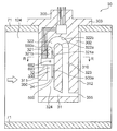
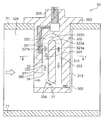
- FIG. 2 is a front view schematically showing the structure of the physical quantity detecting device 30.
- the physical quantity detecting device 30 includes a housing 302.
- the housing 302 has an external connection portion (connector portion) having a flange 303 for fixing the physical quantity detection device 30 to the intake body 71 constituting the main passage 124 and an external terminal for making an electrical connection with an external device. ) 305 and a measuring unit 310 for measuring the flow rate and the like.
- the measuring unit 310 is arranged in the main passage 124 and supported in a cantilever shape by fixing the flange 303 to the intake body (intake pipe) 71.
- the measuring unit 310 arranged in the main passage 124 is provided with a sub-passage 330 that takes in the gas to be measured IA from the main passage 124.
- a support member 603 is arranged in the middle of the sub-passage 330.
- the support member 603 has a flat plate shape, extends over the passage width direction W of the sub-passage in the middle of the sub-passage, and intersects a part of the sub-passage in the passage width direction. It is divided into two flow paths, one on the side (one side) and the other on the back surface 603b side (the other side).
- a flow rate detecting element 602 for measuring the flow rate of the gas to be measured IA flowing through the main passage 124 is provided.
- the support member include a circuit package and a printed circuit board.
- the sub-passage 330 has a first sub-passage 31 and a second sub-passage 32.
- the first sub-passage 31 is a passage formed from the main intake port 350 for taking in the measured gas IA flowing through the main passage 124 to the main outlet 355 for discharging the taken-in measured gas IA.
- the second sub-passage 32 is a flow rate measuring passage formed from the sub-intake port 34 for taking in the gas to be measured IA flowing through the first sub-passage 31 toward the flow rate detecting element 602.
- the sub-passage 330 allows foreign matter such as dust and water to flow mainly into the first sub-passage 31, and clean air containing no such foreign matter can be taken into the second sub-passage 32.
- the gas to be measured IA taken into the sub-passage 330 from the main intake port 350 is divided into the first sub-passage 31 and the second sub-passage 32.
- the gas to be measured IA that has flowed through the second sub-passage 32 flows into the first sub-passage 31 after passing through the flow rate detection element 602, merges with the gas to be measured IA that has flowed through the first sub-passage 31, and is the main outlet. It is discharged from 355.
- the first sub-passage 31 is provided in the measuring unit 310 so as to extend in parallel along the flow direction of the gas to be measured IA flowing through the intake body 71 while being attached to the intake body 71.
- the main intake port 350 and the main outlet 355 are provided on the tip side of the measuring unit 310, respectively, and the main intake port 350 is located on the upstream side of the measuring unit 310 arranged toward the upstream side in the main passage 124. It opens to the end portion 311 and the main outlet 355 opens to the downstream end portion 312 of the measuring unit 310 arranged toward the downstream side in the main passage 124.
- the second sub-passage 32 branches from the first sub-passage 31 at the sub-intake port 34 that opens at an intermediate position of the first sub-passage 31, and extends from the tip end portion of the measurement unit 310 toward the base end portion. Then, it curves in the direction of approaching the downstream end portion 312 of the measurement unit 310 near the base end portion, extends again from the base end portion of the measurement unit 310 toward the tip end portion, and joins the first sub-passage 31. It has a shape to be used.
- the second sub-passage 32 extends linearly from the sub-intake port 34 toward the base end portion of the measuring unit 310, and the support member 603 is arranged at an intermediate position thereof.
- a downstream bent portion 322 that bends to one side in the passage width direction of the first straight portion 321 continuously on the downstream side of the first straight portion 321 and a downstream bent portion 322 that continuously bends from the base end to the tip of the measuring unit 310. It has a second straight line portion 323 that extends linearly toward the portion and connects to the first sub-passage 31.
- the downstream curved portion 322 curves with a constant curvature toward the downstream end portion 312 side, which is one side in the passage width direction of the first straight portion 321 from the upstream side end portion 311 side of the measuring unit 310, and makes a U-turn. It has an arc shape.
- the downstream curved portion 322 has an inner peripheral side curved wall surface 322a having a large curvature on one side in the passage width direction, and an outer peripheral side curved wall surface 322b having a small curvature on the other side in the passage width direction.
- the inner peripheral curved wall surface 322a having a large curvature of the downstream curved portion 322 is continuous with the side wall surface 321a on one side in the passage width direction of the first straight portion 321, and the outer peripheral curved wall surface 322b having a small curvature of the downstream curved portion 322 is the first.
- the straight portion 321 is provided so as to be continuous with the side wall surface 321b on the other side in the passage width direction.
- an upstream curved portion 324 is continuously provided on the upstream side of the first straight portion 321.
- the upstream curved portion 324 is provided between the sub intake port 34 and the first straight portion 321 and is the other side of the first straight portion 321 to the first straight portion 321 in the passage width direction, that is, the measuring unit in the present embodiment. It has a shape that bends toward the upstream end 311 side of 310.
- the upstream bending portion 324 determines the direction of the gas to be measured IA, which is taken into the sub-passage 330 from the main intake port 350 and flows from the upstream end portion 311 of the measuring unit 310 toward the downstream end portion 312, of the measuring unit 310. Change the direction from the tip to the base.
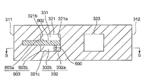
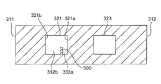
- FIG. 3 is a cross-sectional view taken along the line QQ of FIG.
- the first straight line portion 321 of the second sub-passage 32 is divided into a surface flow path 331 on the surface 603a side of the support member 603 and a back flow path 332 on the back surface 603b side thereof.
- the back flow path 332 is divided into an inner peripheral side passage 332a which is a flow path on one side in the passage width direction and an outer peripheral side passage 332b which is a flow path on the other side in the passage width direction by the dividing wall 500. ..
- the back flow path 332 is divided so that the cross-sectional area of the inner peripheral side passage 332a is smaller than the cross-sectional area of the outer peripheral side passage 332b.
- the dividing wall 500 projects from the bottom surface 321c of the first straight line portion 321 which is the bottom surface of the sub-passage 330 facing the back surface (the other surface) 603b of the support member 603 toward the support member 603 and is supported. It has a height that abuts on the other surface 603b of the member 603.
- the dividing wall 500 is integrally formed with the measuring unit 310, and also functions as a member for positioning and supporting the position of the support member 603 in the sub-passage 330.
- the dividing wall 500 is arranged at a position deviated toward the downstream end portion 312 side of the measuring unit 310, which is one side in the passage width direction from the central position in the passage width direction of the back flow path 332, and is arranged in a position of the inner peripheral side passage 332a.
- the back flow path 332 is divided so that the cross-sectional area is smaller than the cross-sectional area of the outer peripheral side passage 332b.
- the split wall 500 may be the same as or slightly shorter than the length in the flow direction of the fluid flowing through the sub-passage 330 of the support member 603, and as shown in FIG. 2, when the physical quantity detecting device 30 is viewed from the front side. , Has a size hidden on the back surface 603b side of the support member 603.
- the split wall 500 extends along the first straight line portion 321 and has a length extending from the upstream end to the downstream end of the support member 603. ..
- the upstream end of the dividing wall 500 arranged on the upstream side of the first straight portion 321 is arranged at the same position as the upstream end of the support member 603, and the first straight portion 321
- the downstream end of the split wall 500 arranged on the downstream side is arranged at the same position as the downstream end of the support member 603.
- the length of the dividing wall 500 may be shorter than the length extending from the upstream end to the downstream end of the support member 603.
- the upstream end of the split wall 500 may be arranged at a position downstream of the first straight line portion 321 with respect to the upstream end of the support member 603, or the downstream end of the split wall 500.
- the end portion of the first straight line portion 321 may be arranged at a position on the upstream side of the end portion on the downstream side of the support member 603.
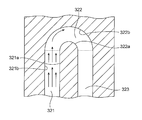
- FIG. 4A is a schematic view of the flow velocity distribution on the intersection of the PP line cross section of FIG. 2 and the SS line cross section of FIG. 3 when the dividing wall is not provided
- FIG. 4B is the flow velocity distribution shown in FIG. 4A. It is a figure explaining the pressure state at the time of flowing into the downstream bending part of the gas to be measured which has.
- the flow velocity distribution of the gas to be measured IA is not optimized in the first straight line portion 321 of the second sub-passage 32. Therefore, for example, as shown in FIG. 4A, the peak of the flow velocity distribution is on the side wall surface 321a on one side of the first straight line portion 321 in the passage width direction rather than on the side wall surface 321b side on the other side in the passage width direction of the first straight portion 321. Was sometimes biased.
- the upstream curved portion 324 is continuously provided on the upstream side of the first straight portion, the gas to be measured IA taken in from the main intake port 350 changes its direction from the first sub-passage 31 and is the first.
- the flow velocity is faster on one side in the passage width direction than on the other side in the passage width direction, and the flow velocity distribution is the passage width of the first straight line portion 321. It was easy to be biased toward the side wall surface 321a, which is one side in the direction.
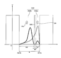
- FIG. 5A is a schematic diagram of the flow velocity distribution on the intersection of the PP line cross section of FIG. 2 and the SS line cross section of FIG. 3 when the dividing wall is provided
- FIG. 5B is the flow velocity distribution shown in FIG. 5A. It is a figure explaining the pressure state at the time of flowing into the downstream bending part of the gas to be measured which has.
- the back flow path 332 is provided with the dividing wall 500, and the dividing wall 500 is a side wall surface on one side in the passage width direction with respect to the central position in the passage width direction of the first straight line portion 321. It is arranged at a position biased toward the 321a side.
- the back flow path 332 is divided into an inner peripheral side passage 332a and an outer peripheral side passage 332b by the dividing wall 500, and the cross-sectional area of the inner peripheral side passage 332a is smaller than that of the outer peripheral side passage 332b.
- the passage width wi of the inner peripheral side passage 332a of the back flow path 332 is narrower than the passage width w of the outer peripheral side passage 332b.
- the passage width w of the outer peripheral side passage 332b is wider than the width wt of the dividing wall 500.
- the gas to be measured IA passing through the back flow path 332 is less likely to flow in the inner peripheral side passage 332a than the outer peripheral side passage 332b, and the gas to be measured IA passing through the back flow path 332 is the first straight line.
- a part of the gas to be measured IA passing through the side wall surface 321a side on one side in the passage width direction of the portion 321 is deflected toward the side wall surface 321b side on the other side in the passage width direction of the first straight line portion 321. Therefore, the flow rate IAo flowing through the outer peripheral side passage 332b is larger than the flow rate IAi flowing through the inner peripheral side passage 332a.
- the resistance of the gas to be measured is reduced, and the gas to be measured IA can easily flow in the sub-passage 32. Therefore, the occurrence of measurement error is reduced by increasing the flow rate of the gas to be measured IA in the passage of the second sub-passage 32 and increasing the detected flow rate of the flow rate detecting element 602.
- the physical quantity detecting device 30 of the present embodiment it is possible to reduce the pressure rise in the downstream bending portion 322 and the pressure loss associated therewith. Therefore, when the flow rate of the measured gas IA in the main passage 124 is low and the inflow amount of the measured gas IA into the sub-passage 330 is small, or when the flow rate of the measured gas IA in the main passage 124 is large, the conventional shape Even when the inflow amount of the gas to be measured IA into the sub-passage 330 becomes small due to the pressure loss in the downstream curved portion 322 in the sub-passage 330 as described above, the flow rate can be detected stably.
- the inner peripheral side passage 332a of the back flow path 332 is not completely closed, and the fluid having a large flow velocity on the side wall surface 321a side which is one side in the passage width direction of the first straight line portion 321 is directly used as the back surface. It can be passed through the flow path 332.
- a simple throttle-shaped resistance member is provided to reduce the cross-sectional area of the entire back flow path 332, a portion of the flow velocity of the gas to be measured IA passing through one side of the back flow path 332 in the passage width direction becomes large. All of them are deflected and decelerated, and the pressure rise in the back flow path 332 becomes large, which in turn increases the resistance in the passage.
- the divided passage divided by the divided wall 500 as in the present embodiment, it is possible to prevent the pressure increase of the back flow path 332 and reduce the resistance in the passage.
- the sub-passage 330 extends in a straight line and is continuous with the first straight line portion 321 on which the support member 603 is arranged and the downstream side of the first straight line portion 321.
- the straight portion 321 has a downstream bent portion 322 that bends on one side in the passage width direction, and the first straight portion 321 has a back flow path 332 of the support member 603 and an inner peripheral side passage 332a on one side in the passage width direction.
- a dividing wall 500 is provided to divide into two flow paths of the outer peripheral side passage 332b on the other side, and of the inner peripheral side passage 332a and the outer peripheral side passage 332b divided by the dividing wall 500, the inner peripheral side passage 332a
- the cross-sectional area is smaller than the cross-sectional area of the outer peripheral side passage 332b.
- the split wall 500 is provided in the back flow path 332, and the cross-sectional area of the inner peripheral side passage 332a of the back flow path 332 is smaller than the cross-sectional area of the outer peripheral side passage 332b.
- the bias of the flow in the straight portion 321 is suppressed, the flow rate distribution is optimized, and the resistance in the passage in the downstream curved portion 322 is reduced.
- the flow rate in the sub-passage increases, the flow rate detected by the flow rate detecting element 602 increases, and the occurrence of measurement error is reduced. Therefore, it is possible to prevent variations in error under a plurality of pulsating conditions.
- the dividing wall 500 is provided only on the back flow path 332, not on the front flow path 331 side. More specifically, the split wall 500 has a height that protrudes from the bottom surface 321c of the sub-passage facing the back surface 603b of the support member 603 toward the support member 603 and abuts on the back surface 603b of the support member 603. The straight portion 321 does not project toward the surface 603a of the support member 603.
- the dividing wall 500 does not cause disturbance such as a vortex to the gas to be measured IA flowing through the surface flow path 331 of the support member 603, and the flow rate detecting element 602 arranged on the surface 603a of the support member 603. It is possible to prevent the detection accuracy of the gas from being affected. Further, the split wall 500 can position the position of the support member 603 in the sub-passage 330 by abutting the back surface 603b of the support member 603, and the flow path areas of the front flow path 331 and the back flow path 332. Individual differences can be eliminated.
- the physical quantity detecting device 30 of the present embodiment increases the flow rate to the flow rate detecting element 602 side in the sub-passage 330, and optimizes the bias of the flow velocity distribution existing on the upstream side of the downstream curved portion 322. It is possible to reduce the flow velocity component that collides with the outer peripheral side curved wall surface 322b of the downstream curved portion 322. Therefore, by suppressing the generation of the high-pressure region Sa in the downstream bending portion 322, reducing the pressure loss in the sub-passage 330, increasing the flow rate flowing into the sub-passage 330, and increasing the detection amount of the flow rate detection element 602. , The detection performance can be improved.
- FIG. 6 is a front view schematically showing the structure of the physical quantity detecting device according to the second embodiment
- FIG. 7 is a schematic view of an RR cross section of FIG.
- the dividing wall 500 that divides the back passage of the flow rate detecting element 602 is extended to the upstream side and the downstream side along the extending direction of the first straight line portion 321 to support it.
- the shape is longer than the length of the member 603 in the flow direction.
- the height of the dividing wall 500 is constant from the upstream end to the downstream end, and as shown in FIG. 7, the flow rate detection of the support member 603 is performed even at a position not on the back surface side of the support member.
- the height in the element 602 direction does not change.
- the split wall 500 includes an upstream extension wall 500a extending toward the upstream side of the support member 603 along the first straight line portion 321 and a first straight line portion of the support member 603 along the first straight line portion 321. It has a downstream extension wall 500b that extends toward the downstream side of 321.
- the upstream extension wall 500a and the downstream extension wall 500b have the same height as the portion of the dividing wall 500 that divides the back flow path 332.
- the height of the dividing wall 500 does not reach the surface flow path 331 which is the passage on the surface 603a side of the support member 603, the flow of the gas to be measured IA passing through the flow rate detecting element 602 is disturbed. None.
- the length of the dividing wall 500 is longer than that of the first embodiment, the bias of the flow in the first straight line portion 321 can be further suppressed as compared with the first embodiment. Therefore, as compared with the first embodiment, the flow rate distribution of the gas to be measured IA in the second sub-passage 32 is optimized, the resistance in the passage in the downstream curved portion 322 is reduced, and the gas to be measured IA passes through the sub-passage 32. It becomes easier to flow. Therefore, the occurrence of measurement error is reduced by increasing the flow rate of the gas to be measured IA in the passage of the second sub-passage 32 and increasing the detected flow rate of the flow rate detecting element 602. Therefore, it is possible to prevent the detection accuracy from being lowered due to the change in the error according to the pulsation condition.
- FIG. 8 is a front view schematically showing the structure of the physical quantity detecting device according to the third embodiment.
- FIG. 8 is a schematic view of the physical quantity detecting device 30 viewed from the same direction as in FIGS. 2 and 6, but the cross section of the passage is a view on the SS cross section shown in FIG. The cross section of 332 is shown. Therefore, the flow rate detection element 602 and the support member 603 are shown by broken lines.
- the back flow path 332 is divided into an inner peripheral side passage 332a and an outer peripheral side passage 332b by the dividing wall 501.
- the dividing wall 501 is provided at an angle with respect to the first straight line portion 321. Unlike the dividing wall 500 of the first embodiment, the dividing wall 501 is not provided parallel to the flow direction of the first straight line portion 321. The dividing wall 501 is inclined obliquely with respect to the first straight line portion 321 so that the cross-sectional area of the inner peripheral side passage 332a gradually expands or narrows as the first straight line portion 321 moves from the upstream side to the downstream side. It is provided.
- the minimum cross-sectional area of the inner peripheral side passage 332a is smaller than the minimum cross-sectional area of the outer peripheral side passage 332b. ..
- the passage cross-sectional area on the upstream side of the inner peripheral side passage 332a is narrow and the passage cross-sectional area on the downstream side is wide with respect to the flow direction of the gas to be measured IA in the first straight line portion 321. ..
- the shape may be such that the passage cross-sectional area on the upstream side of the inner peripheral side passage 332a is wide and the passage cross-sectional area on the downstream side is narrow with respect to the flow direction.
- the gas to be measured IA flowing in the vicinity of the inner peripheral side passage 332a is deflected to the outer peripheral side, and the component in which the gas to be measured IA collides with the downstream bending portion 322 becomes small. .. Therefore, the resistance in the passage is reduced and the detected flow rate of the flow rate detecting element 602 is increased, so that the occurrence of measurement error is reduced.
- FIG. 9 is a front view schematically showing the structure of the physical quantity detecting device according to the fourth embodiment.
- FIG. 9 is a schematic view of the physical quantity detecting device 30 viewed from the same direction as in FIG. 8, but the cross section of the passage is a view on the SS cross section shown in FIG. 3, and is a cross section of the back flow path 332. Is shown. Therefore, the flow rate detection element 602 and the support member 603 are shown by broken lines.
- an obstacle 502 is arranged in the back flow path 332 instead of the dividing walls 500 and 501 in each of the above-described embodiments, and the back flow path 332 is set to the inner peripheral side by the obstacle 502. It is configured to be divided into a passage 332a and an outer peripheral side passage 332b.
- the obstacle 502 is composed of three rod-shaped members, and is a position where the back flow path 332 is divided into the inner peripheral side passage 332a and the outer peripheral side passage 332b, similar to the dividing wall 500 in FIG.
- the cross-sectional area of the inner peripheral side passage 332a is smaller than the cross-sectional area of the outer peripheral side passage 332b, and the passages are arranged side by side at predetermined intervals.
- the number of obstacles is not limited to the three of the present embodiment, and may be less than or greater than three.
- the obstacle 502 is installed in a range smaller than the length of the support member 603 of the flow rate detecting element 602 in the flow direction, and is hidden by the support member 603 when viewed from the front side.
- the obstacle 502 may be installed in a range larger than the length of the support member 603 in the flow direction.
- the height of the obstacle 502 is lower than the surface 603a of the support member 603 and does not reach the surface flow path 331.
- a plurality of obstacles 502 are arranged side by side in parallel with the flow direction of the first sub-passage 31, but the plurality of obstacles do not have to be parallel to the flow direction. ..
- the gas to be measured IA flowing through the back flow path 332 is deflected from the inner peripheral side passage 332a to the outer peripheral side passage 332b, and is gently deflected when the flow reaches the downstream curved portion 322. Therefore, the pressure increase in the downstream bending portion 322 is reduced, the resistance in the passage is reduced, the detection amount of the flow rate detecting element 602 is increased, and the occurrence of measurement error is reduced.
- the present invention is not limited to the above-described embodiments, and various designs are designed without departing from the spirit of the present invention described in the claims. You can make changes.
- the above-described embodiment has been described in detail in order to explain the present invention in an easy-to-understand manner, and is not necessarily limited to the one including all the described configurations.
- it is possible to replace a part of the configuration of one embodiment with the configuration of another embodiment and it is also possible to add the configuration of another embodiment to the configuration of one embodiment.
Landscapes
- Physics & Mathematics (AREA)
- General Physics & Mathematics (AREA)
- Fluid Mechanics (AREA)
- Chemical & Material Sciences (AREA)
- Engineering & Computer Science (AREA)
- Combustion & Propulsion (AREA)
- Measuring Volume Flow (AREA)
Abstract
物理量検出装置において、副通路内の流れの偏りを抑制し、通路内抵抗を低減することで、計測誤差の発生を低減する。 本発明の物理量検出装置30は、主通路内に配置される計測部310と、主通路から被計測気体を取り込む副通路330と、副通路の一部を通路幅方向に交差する方向一方面側と他方面側の2つの流路に分割する支持部材603と、支持部材の一方面に配置される流量検出素子602とを備えている。そして、副通路は、支持部材が配置される直線部321と、直線部の通路幅方向一方側に曲がる下流曲がり部322を有しており、直線部には、支持部材の他方面側の流路を通路幅方向一方側と他方側の2つの流路に分割する分割壁500が設けられ、通路幅方向一方側の流路の断面積が前記通路幅方向他方側の流路の断面積よりも小さいことを特徴とする。
Description
本発明は、例えば内燃機関の吸入空気の物理量を検出する物理量検出装置に関する。
例えば特許文献1には、吸気通路の内壁から通路中心に向かって計測部が突出し、その計測部内に、流れを取り込むための副通路が配置され、前記屈曲した副通路を跨ぐように流量検出素子が配置された物理量検出装置の構成が示されている。上記した物理量検出装置では検出素子の上流側に検出素子を保護する板状部材が設置されており、副通路に流れこむ汚損物から検出素子が保護される。この時、検出素子を通過する流れの速度が低下するため、検出素子の支持部により分割された通路内に抵抗部材を設置することで、流速を増加させる物理量検出装置が提案されている。
特許文献1の構成では、検出素子近傍の流速を増加させるために副通路内に抵抗部材を設置しているが、抵抗部材は対称に設置された構造であり、検出素子近傍に単純な増速効果を得るのみであり、通路内全体の流速分布を考慮していない。したがって、場合によっては、通路内の圧力損失が増大し、通路内の流速が低下して被計測気体の流量が減少するおそれがあり、脈動条件に応じて誤差が変化し、検出精度が低下することが懸念される。
本発明は、上記の点に鑑みてなされたものであり、その目的とするところは、副通路内の流速分布の適正化を図り、複数の脈動条件において誤差のばらつきを防ぐことができる物理量検出装置を提供することである。
上記課題を解決する本発明の物理量検出装置は、主通路を流れる被計測気体の物理量を検出する物理量検出装置であって、前記主通路内に配置される計測部と、該計測部に設けられて前記主通路から前記被計測気体を取り込む副通路と、該副通路の通路途中で前記副通路の通路幅方向に亘って延在して前記副通路の一部を前記通路幅方向に交差する方向一方面側と他方面側の2つの流路に分割する支持部材と、該支持部材の一方面に配置されて前記副通路内で前記被計測気体の流量を検出する流量検出素子と、を備え、前記副通路は、直線状に延在して前記支持部材が配置される直線部と、該直線部の下流側に連続して前記直線部の通路幅方向一方側に曲がる下流曲がり部を有し、前記直線部には、前記支持部材の他方面側の流路を通路幅方向一方側と他方側の2つの流路に分割する分割壁が設けられており、該分割壁によって分割された前記通路幅方向一方側と他方側の2つの流路のうち、前記通路幅方向一方側の流路の断面積が前記通路幅方向他方側の流路の断面積よりも小さいことを特徴とする。
本発明によれば、副通路内の流速分布の適正化を図り、複数の脈動条件において誤差のばらつきを防ぐことができる。本発明に関連する更なる特徴は、本明細書の記述、添付図面から明らかになるものである。また、上記した以外の、課題、構成及び効果は、以下の実施形態の説明により明らかにされる。
以下に説明する、発明を実施するための形態(以下、実施形態)は、実際の製品として要望されている種々の課題を解決しており、特に車両の吸入空気の物理量を検出する検出装置として使用するために望ましい色々な課題を解決し、種々の効果を奏している。下記実施形態が解決している色々な課題の内の一つが、上述した発明が解決しようとする課題の欄に記載した内容であり、また下記実施形態が奏する種々の効果のうちの一つが、発明の効果の欄に記載された効果である。下記実施形態が解決している色々な課題について、さらに下記実施形態により奏される種々の効果について、下記実施形態の説明の中で述べる。従って、下記実施形態の中で述べる、実施形態が解決している課題や効果は、発明が解決しようとする課題の欄や発明の効果の欄の内容以外の内容についても記載されている。
以下の実施形態で、同一の参照符号は、図番が異なっていても同一の構成を示しており、同じ作用効果を成す。既に説明済みの構成について、図に参照符号のみを付し、説明を省略する場合がある。
図1は、電子燃料噴射方式の内燃機関制御システムに本発明に係る物理量検出装置を使用した一実施形態を示すシステム図である。
エンジンシリンダ112とエンジンピストン114を備える内燃機関110の動作に基づき、吸入空気が被計測気体IAとしてエアクリーナ122から吸入され、主通路124である例えば吸気ボディと、スロットルボディ126と吸気マニホールド128を介してエンジンシリンダ112の燃焼室に導かれる。燃焼室に導かれる吸入空気である被計測気体IAの物理量は、本発明に係る物理量検出装置30で検出され、その検出された物理量に基づいて燃料噴射弁152より燃料が供給され、被計測気体IAと共に混合気の状態で燃焼室に導かれる。なお、本実施形態では、燃料噴射弁152は内燃機関の吸気ポートに設けられ、吸気ポートに噴射された燃料が被計測気体IAと共に混合気を形成し、吸気弁116を介して燃焼室に導かれ、燃焼して機械エネルギを発生する。
燃焼室に導かれた燃料および空気は、燃料と空気の混合状態を成しており、点火プラグ154の火花着火により、爆発的に燃焼し、機械エネルギを発生する。燃焼後の気体は排気弁118から排気管に導かれ、排気ガスEAとして排気管から車外へ排出される。前記燃焼室に導かれる吸入空気である被計測気体IAの流量は、アクセルペダルの操作に基づいてその開度が変化するスロットルバルブ132により制御される。前記燃焼室に導かれる吸入空気の流量に基づいて燃料供給量が制御され、運転者はスロットルバルブ132の開度を制御して前記燃焼室に導かれる吸入空気の流量を制御することにより、内燃機関が発生する機械エネルギを制御することができる。
エアクリーナ122から取り込まれ、主通路124を流れる吸入空気である被計測気体IAの流量、温度、湿度、圧力などの物理量が物理量検出装置30により検出され、物理量検出装置30から吸入空気の物理量を表す電気信号が制御装置200に入力される。また、スロットルバルブ132の開度を計測するスロットル角度センサ144の出力が制御装置200に入力され、さらに内燃機関のエンジンピストン114や吸気弁116や排気弁118の位置や状態、さらに内燃機関の回転速度を計測するために、回転角度センサ146の出力が、制御装置200に入力される。排気ガスEAの状態から燃焼量と空気量の混合比の状態を計測するために、酸素センサ148の出力が制御装置200に入力される。
制御装置200は、物理量検出装置30の出力である吸入空気の物理量と、回転角度センサ146の出力に基づき計測された内燃機関の回転速度とに基づいて、燃料噴射量や点火時期を演算する。これらの演算結果に基づいて、燃料噴射弁152から供給される燃料量、また点火プラグ154により点火される点火時期が制御される。燃料供給量や点火時期は、実際にはさらに物理量検出装置30で検出される温度やスロットル角度の変化状態、エンジン回転速度の変化状態、酸素センサ148で計測された空燃比の状態に基づいて、きめ細かく制御される。制御装置200は、さらに内燃機関のアイドル運転状態において、スロットルバルブ132をバイパスする空気量をアイドルエアコントロールバルブ156により制御し、アイドル運転状態での内燃機関の回転速度を制御する。
内燃機関の主要な制御量である燃料供給量や点火時期はいずれも物理量検出装置30の出力を主パラメータとして演算される。したがって、物理量検出装置30の検出精度の向上や、経時変化の抑制、信頼性の向上が、車両の制御精度の向上や信頼性の確保に関して重要である。
特に近年、車両の省燃費に関する要望が非常に高く、また排気ガス浄化に関する要望が非常に高い。これらの要望に応えるには、物理量検出装置30により検出される吸入空気(被計測気体IA)の物理量の検出精度の向上が極めて重要である。また、物理量検出装置30が高い信頼性を維持していることも大切である。
物理量検出装置30が搭載される車両は、温度や湿度の変化が大きい環境で使用される。物理量検出装置30は、その使用環境における温度や湿度の変化への対応や、塵埃や汚染物質などへの対応も、考慮されていることが望ましい。
また、物理量検出装置30は、内燃機関からの発熱の影響を受ける吸気管に装着される。このため、内燃機関の発熱が主通路124である吸気管を介して物理量検出装置30に伝わる。物理量検出装置30は、被計測気体IAと熱伝達を行うことにより被計測気体IAの流量を検出するので、外部からの熱の影響をできるだけ抑制することが重要である。
車に搭載される物理量検出装置30は、以下で説明するように、単に発明が解決しようとする課題の欄に記載された課題を解決し、発明の効果の欄に記載された効果を奏するのみでなく、以下で説明するように、上述した色々な課題を十分に考慮し、製品として求められている色々な課題を解決し、色々な効果を奏している。物理量検出装置30が解決する具体的な課題や奏する具体的な効果は、以下の実施形態の記載の中で説明する。
<第1実施形態>
以下、本発明の第1実施形態について図に基づいて説明する。
以下、本発明の第1実施形態について図に基づいて説明する。
図2は、物理量検出装置30の構造を模式的に示す正面図である。
物理量検出装置30は、ハウジング302を備えている。ハウジング302は、物理量検出装置30を、主通路124を構成する吸気ボディ71に固定するためのフランジ303と、外部機器との電気的な接続を行うための外部端子を有する外部接続部(コネクタ部)305と、流量等を計測するための計測部310を有している。物理量検出装置30は、フランジ303を吸気ボディ(吸気管)71に固定することにより、計測部310が主通路124内に配置されて片持ち状に支持される。
物理量検出装置30は、ハウジング302を備えている。ハウジング302は、物理量検出装置30を、主通路124を構成する吸気ボディ71に固定するためのフランジ303と、外部機器との電気的な接続を行うための外部端子を有する外部接続部(コネクタ部)305と、流量等を計測するための計測部310を有している。物理量検出装置30は、フランジ303を吸気ボディ(吸気管)71に固定することにより、計測部310が主通路124内に配置されて片持ち状に支持される。
主通路124内に配置される計測部310には、主通路124から被計測気体IAを取り込む副通路330が設けられている。そして、副通路330の通路途中には、支持部材603が配置されている。支持部材603は、平板形状を有しており、副通路の通路途中で副通路の通路幅方向Wに亘って延在して副通路の一部を通路幅方向に交差する方向である表面603a側(一方面側)とその背面603b側(他方面側)の2つの流路に分割している。支持部材603の表面には、主通路124を流れる被計測気体IAの流量を計測するための流量検出素子602が設けられている。支持部材としては、回路パッケージやプリント基板が挙げられる。
副通路330は、第1副通路31と第2副通路32を有する。第1副通路31は、主通路124を流れる被計測気体IAを取り込む主取り込み口350から、取り込んだ被計測気体IAを排出する主出口355まで形成された通路である。ここでは、被計測気体IAが順流の場合を示す。第2副通路32は、第1副通路31に流れる被計測気体IAを取り込む副取込口34から、流量検出素子602に向かって形成された流量計測用通路である。副通路330は、ダストや水等の異物を主に第1副通路31に流し、これらの異物を含まないきれいな空気を第2副通路32に取り込むことができる。
主取込口350から副通路330に取り込まれた被計測気体IAは、第1副通路31と第2副通路32に分流される。第2副通路32を流れた被計測気体IAは、流量検出素子602を通過した後、第1副通路31に流入し、第1副通路31を流れた被計測気体IAと合流して主出口355から排出される。
第1副通路31は、吸気ボディ71に取り付けられた状態で吸気ボディ71を流れる被計測気体IAの流れ方向に沿って平行に延在するように計測部310に設けられている。
主取込口350と主出口355は、計測部310の先端側にそれぞれ設けられており、主取込口350は、主通路124内で上流側に向かって配置される計測部310の上流側端部311に開口し、主出口355は、主通路124内で下流側に向かって配置される計測部310の下流側端部312に開口している。
主取込口350と主出口355は、計測部310の先端側にそれぞれ設けられており、主取込口350は、主通路124内で上流側に向かって配置される計測部310の上流側端部311に開口し、主出口355は、主通路124内で下流側に向かって配置される計測部310の下流側端部312に開口している。
第2副通路32は、第1副通路31の途中位置に開口する副取込口34において第1副通路31から分岐し、計測部310の先端部から基端部に向かって延在する。そして、基端部近傍で計測部310の下流側端部312に接近する方向にカーブして、再び計測部310の基端部から先端部に向かって延在し、第1副通路31に合流する形状を有している。
第2副通路32は、副取込口34から計測部310の基端部に向かって直線状に延在してその途中位置に支持部材603が配置される第1直線部(直線部)321と、第1直線部321の下流側に連続して第1直線部321の通路幅方向一方側に曲がる下流曲がり部322と、下流曲がり部322に連続して計測部310の基端部から先端部に向かって直線状に延在して第1副通路31につながる第2直線部323を有している。
下流曲がり部322は、計測部310の上流側端部311側から第1直線部321の通路幅方向一方側である下流側端部312側に向かって一定の曲率でカーブしてUターンする半円弧形状を有している。下流曲がり部322は、通路幅方向一方側に曲率の大きな内周側曲がり壁面322aを有し、通路幅方向他方側に曲率の小さな外周側曲がり壁面322bを有している。下流曲がり部322の曲率の大きな内周側曲がり壁面322aは第1直線部321の通路幅方向一方側の側壁面321aに連続し、下流曲がり部322の曲率の小さな外周側曲がり壁面322bは第1直線部321の通路幅方向他方側の側壁面321bに連続するように設けられている。
そして、第1直線部321の上流側には上流曲がり部324が連続して設けられている。上流曲がり部324は、副取込口34と第1直線部321との間に設けられており、第1直線部321から第1直線部321の通路幅方向他方側、本実施形態では計測部310の上流側端部311側に曲がる形状を有している。上流曲がり部324は、主取込口350から副通路330に取り込まれて計測部310の上流側端部311から下流側端部312に向かって流れる被計測気体IAの向きを、計測部310の先端部から基端部に向かう方向に変更させる。
次に、本実施形態により通路内の流れの偏りが抑制され、圧力損失が抑制されることで、計測誤差の発生が低減される構成について説明する。
図3は、図2のQ-Q断面図である。
第2副通路32の第1直線部321は、支持部材603の表面603a側の表面流路331と、その背面603b側の背面流路332とに分割されている。そして、背面流路332は、分割壁500によって、通路幅方向一方側の流路となる内周側通路332aと、通路幅方向他方側の流路となる外周側通路332bとに分割されている。背面流路332は、内周側通路332aの断面積の方が、外周側通路332bの断面積よりも小さくなるように分割されている。
第2副通路32の第1直線部321は、支持部材603の表面603a側の表面流路331と、その背面603b側の背面流路332とに分割されている。そして、背面流路332は、分割壁500によって、通路幅方向一方側の流路となる内周側通路332aと、通路幅方向他方側の流路となる外周側通路332bとに分割されている。背面流路332は、内周側通路332aの断面積の方が、外周側通路332bの断面積よりも小さくなるように分割されている。
分割壁500は、図3に示すように、支持部材603の背面(他方面)603bに対向する副通路330の底面である第1直線部321の底面321cから支持部材603に向かって突出して支持部材603の他方面603bに当接する高さを有している。分割壁500は、計測部310と一体に形成されており、副通路330内における支持部材603の位置を位置決め支持する部材としても機能する。分割壁500は、背面流路332の通路幅方向中央位置よりも通路幅方向一方側である計測部310の下流側端部312側に偏倚した位置に配置されており、内周側通路332aの断面積の方が、外周側通路332bの断面積よりも小さくなるように背面流路332を分割している。
分割壁500は、支持部材603の副通路330を流れる流体の流れ方向の長さと同じ、あるいは、若干短くてもよく、図2に示すように、正面側から物理量検出装置30を見た場合に、支持部材603の背面603b側に隠れる大きさを有している。分割壁500は、本実施形態では、第1直線部321に沿って延在して、支持部材603の上流側の端部から下流側の端部までの間に亘る長さを有している。つまり、第1直線部321の上流側に配置される分割壁500の上流側の端部は、支持部材603の上流側の端部と同一の位置に配置されており、第1直線部321の下流側に配置される分割壁500の下流側の端部は、支持部材603の下流側の端部と同一の位置に配置されている。
分割壁500の長さは、支持部材603の上流側の端部から下流側の端部までの間に亘る長さよりも短くてもよい。例えば、分割壁500の上流側の端部は、支持部材603の上流側の端部よりも第1直線部321の下流側の位置に配置されていてもよく、また、分割壁500の下流側の端部は、支持部材603の下流側の端部よりも第1直線部321の上流側の位置に配置されていてもよい。
図4Aは、分割壁が設けられていない場合における図2のP-P線断面と図3のS-S線断面の交線上の流速分布の概略図、図4Bは、図4Aに示す流速分布を有する被計測気体が下流曲がり部に流入した場合の圧力状態を説明する図である。
背面流路332に分割壁500が設けられていない従来の場合は、第2副通路32の第1直線部321において被計測気体IAの流速分布が適正化されていなかった。したがって、例えば、図4Aに示すように、第1直線部321の通路幅方向他方側の側壁面321b側よりも第1直線部321の通路幅方向一方側の側壁面321a側に流速分布のピークが偏る場合があった。特に、第1直線部の上流側に上流曲がり部324が連続して設けられている場合には、主取込口350から取り込んだ被計測気体IAが第1副通路31から方向を変えつつ第2副通路32に流れ込むので、被計測気体IAに遠心力が作用し、通路幅方向他方側よりも通路幅方向一方側の方が流速が速くなり、流速分布が第1直線部321の通路幅方向一方側である側壁面321a側に偏りやすかった。
このように流速分布が第1直線部321の通路幅方向一方側の側壁面321a側に偏った被計測気体IAが、そのまま下流曲がり部322に流入すると、下流曲がり部322の曲率の小さな外周側曲がり壁面322bに対して衝突する流速成分が大きく、図4Bに示すように、衝突により下流曲がり部322において局所的に圧力が増加して高圧化する高圧領域Saが発生するおそれがある。このような高圧領域Saの発生は、通路内の流量抵抗を増加させ、被計測気体IAを流れにくくし、第2副通路32の通路内の流量を低下させ、流量検出素子602の検出流量の低下により、計測誤差の発生が増大される。したがって、脈動条件に応じて誤差が変化し、検出精度が低下するおそれがある。
図5Aは、分割壁が設けられている場合における図2のP-P線断面と図3のS-S線断面の交線上の流速分布の概略図、図5Bは、図5Aに示す流速分布を有する被計測気体が下流曲がり部に流入した場合の圧力状態を説明する図である。
これに対し、本実施形態では、背面流路332に分割壁500が設けられており、分割壁500は、第1直線部321の通路幅方向中央位置よりも通路幅方向一方側である側壁面321a側に偏倚した位置に配置されている。背面流路332は、分割壁500によって内周側通路332aと外周側通路332bとに分割されており、外周側通路332bよりも内周側通路332aの方が断面積が小さくなっている。本実施形態では、背面流路332の内周側通路332aの通路幅wiは、外周側通路332bの通路幅woよりも狭くなっている。そして、外周側通路332bの通路幅woは、分割壁500の幅wtよりも広くなっている。
かかる構成により、背面流路332を通過する被計測気体IAは、外周側通路332bよりも内周側通路332aの方が流れにくく、背面流路332を通過する被計測気体IAは、第1直線部321の通路幅方向一方側である側壁面321a側を通過する被計測気体IAの一部が、第1直線部321の通路幅方向他方側である側壁面321b側へ偏向される。したがって、外周側通路332bを流れる流量IAoの方が内周側通路332aを流れる流量IAiよりも多くなる。これにより、例えば、図4Aに示すように第1直線部321に流入する被計測気体IAの流速分布が第1直線部321の通路幅方向一方側である側壁面321a側に偏っていた場合には、図5Aに示すように流速分布のピークを背面流路332の通路幅方向中央位置に移動させることができる。
流速分布が第1直線部321の通路幅方向他方側である側壁面321b側に移動された被計測気体IAは、下流曲がり部322に流入すると、図5Bに示すように、下流曲がり部322の曲率の小さな外周側曲がり壁面322bに沿って緩やかに偏向される。したがって、背面流路332に分割壁500が設けられていない従来構造と比較して、下流曲がり部322の外周側曲がり壁面322bに衝突する流速成分が減少し、圧力上昇を低減するとともに、曲がり部の抵抗が低減され、被計測気体IAが副通路32内を流れやすくなる。したがって、第2副通路32の通路内における被計測気体IAの流量を増加させ、流量検出素子602の検出流量の増加により、計測誤差の発生が低減される。
本実施形態の物理量検出装置30によれば、下流曲がり部322における圧力上昇およびそれに伴う圧力損失を低減することができる。したがって、主通路124内における被計測気体IAの流量が低く、被計測気体IAの副通路330への流入量が小さくなる場合や、主通路124内における被計測気体IAの流量が大きく、従来形状のように副通路330内の下流曲がり部322における圧力損失により副通路330への被計測気体IAの流入量が小さくなってしまう場合でも、安定して流量を検出することができる。
本実施形態では、背面流路332の内周側通路332aを完全に閉塞するものではなく、第1直線部321の通路幅方向一方側である側壁面321a側の流速が大きな流体を、そのまま背面流路332に通過させることができる。例えば単純な絞り形状の抵抗部材を設けて、背面流路332全体の断面積を小さくしてしまうと、背面流路332の通路幅方向一方側を通過する被計測気体IAの流速の大きな部分が全て偏向および減速されてしまい、背面流路332の圧力上昇が大きくなり、かえって通路内抵抗を増大させてしまう。
これに対し、本実施形態のように、分割壁500により分割した分割通路であれば、背面流路332の圧力上昇も防ぐことができ、通路内の抵抗が低減される。
これに対し、本実施形態のように、分割壁500により分割した分割通路であれば、背面流路332の圧力上昇も防ぐことができ、通路内の抵抗が低減される。
本実施形態の物理量検出装置30では、副通路330は、直線状に延在して支持部材603が配置される第1直線部321と、第1直線部321の下流側に連続して第1直線部321の通路幅方向一方側に曲がる下流曲がり部322を有しており、第1直線部321には、支持部材603の背面流路332を通路幅方向一方側の内周側通路332aと他方側の外周側通路332bの2つの流路に分割する分割壁500が設けられており、分割壁500によって分割された内周側通路332aと外周側通路332bのうち、内周側通路332aの断面積が外周側通路332bの断面積よりも小さい構成を有している。
本実施形態によれば、背面流路332に分割壁500が設けられ、背面流路332の内周側通路332aの断面積が外周側通路332bの断面積よりも小さくなっているので、第1直線部321における流れの偏りが抑制され、流量分布が適正化され、下流曲がり部322における通路内の抵抗が低減される。その結果、副通路内の流量が増加し、流量検出素子602が検出する流量が増加して、計測誤差の発生が低減される。したがって、複数の脈動条件において誤差のばらつきを防ぐことができる。
本実施形態の物理量検出装置30では、分割壁500は、背面流路332のみに設けられており、表面流路331側には設けられていない。より詳しくは、分割壁500は、支持部材603の背面603bに対向する副通路の底面321cから支持部材603に向かって突出して支持部材603の背面603bに当接する高さを有しており、第1直線部321において支持部材603の表面603a側には突出していない。
したがって、分割壁500が、支持部材603の表面流路331を流れる被計測気体IAに対して渦流などの外乱を生じさせることはなく、支持部材603の表面603aに配置されている流量検出素子602の検出精度に影響を与えるのを防ぐことができる。また、分割壁500は、支持部材603の背面603bに当接させることによって、副通路330内における支持部材603の位置を位置決めすることができ、表面流路331と背面流路332の流路面積の個体差をなくすことができる。
本実施形態の物理量検出装置30は、副通路330内において流量検出素子602側への流量を増加させると共に、下流曲がり部322に対して、その上流側に存在する流速分布の偏りを適性化し、下流曲がり部322の外周側曲がり壁面322bに衝突する流速成分を減少させることができる。したがって、下流曲がり部322における高圧領域Saの発生を抑制し、副通路330における圧力損失を減少させ、副通路330内に流入する流量を増加させ、流量検出素子602の検出量を増加させることで、検出性能を向上させることができる。
<第2実施形態>
次に、図6及び図7を用いて、本発明に係る第2実施形態について説明する。なお、第1実施形態と同様の構成については同一の符号を付することで詳細な説明を省略する。図6は、第2実施形態における物理量検出装置の構造を模式的に示す正面図、図7は、図6のR-R断面の概略図である。
次に、図6及び図7を用いて、本発明に係る第2実施形態について説明する。なお、第1実施形態と同様の構成については同一の符号を付することで詳細な説明を省略する。図6は、第2実施形態における物理量検出装置の構造を模式的に示す正面図、図7は、図6のR-R断面の概略図である。
本実施形態において特徴的なことは、流量検出素子602の背面側通路を分割する分割壁500が、第1直線部321の延在方向に沿って上流側と下流側にそれぞれ延長されて、支持部材603の流れ方向の長さよりも長い形状となっていることである。
分割壁500は、上流側の端部から下流側の端部まで高さが一定であり、図7に示すように、支持部材の背面側にない位置であっても、支持部材603の流量検出素子602方向の高さは変化しない。分割壁500は、第1直線部321に沿って支持部材603よりも上流側に向かって延長された上流側延長壁500aと、第1直線部321に沿って支持部材603よりも第1直線部321の下流側に向かって延長された下流側延長壁500bとを有する。上流側延長壁500aと下流側延長壁500bは、分割壁500の背面流路332を分割している部分と同じ高さを有している。
本実施形態によれば、分割壁500の高さが支持部材603の表面603a側の通路である表面流路331まで達していないので、流量検出素子602を通過する被計測気体IAの流れを乱すことがない。
そして、第1実施形態よりも分割壁500の長さが延長されているので、第1直線部321における流れの偏りを第1実施形態よりも更に抑制することができる。したがって、第1実施形態よりも、第2副通路32における被計測気体IAの流量分布が適正化され、下流曲がり部322における通路内の抵抗が低減され、被計測気体IAが副通路32内を流れやすくなる。したがって、第2副通路32の通路内における被計測気体IAの流量を増加させ、流量検出素子602の検出流量の増加により、計測誤差の発生が低減される。
したがって、脈動条件に応じた誤差の変化により検出精度が低下するのを防ぐことができる。
したがって、脈動条件に応じた誤差の変化により検出精度が低下するのを防ぐことができる。
<第3実施形態>
次に、図8を用いて、本発明に係る第3実施形態について説明する。なお、上述の各実施形態と同様の構成については同一の符号を付することで詳細な説明を省略する。
次に、図8を用いて、本発明に係る第3実施形態について説明する。なお、上述の各実施形態と同様の構成については同一の符号を付することで詳細な説明を省略する。
図8は、第3実施形態における物理量検出装置の構造を模式的に示す正面図である。図8は、図2や図6と同様の方向から物理量検出装置30を見た概略図であるが、通路の断面としては図3に示したS-S断面上の図であり、背面流路332の断面を示している。
そのため、流量検出素子602と支持部材603は破線で示した。この図において、背面流路332は、分割壁501により内周側通路332aと外周側通路332bに分割される。
そのため、流量検出素子602と支持部材603は破線で示した。この図において、背面流路332は、分割壁501により内周側通路332aと外周側通路332bに分割される。
本実施形態において特徴的なことは、第1直線部321に対して分割壁501を傾けて設けたことである。分割壁501は、第1実施形態の分割壁500とは異なり、第1直線部321の流れ方向に対して平行に設けられていない。分割壁501は、第1直線部321の上流側から下流側に移行するにしたがって内周側通路332aの断面積が漸次広がる或いは狭くなるように、第1直線部321に対して斜めに傾いて設けられている。
そして、図8中のT-T断面から下流側を見た際に、内周側通路332aの断面積の最小部が、外周側通路332bの断面積の最小部よりも小さい形状となっている。本実施形態では、第1直線部321における被計測気体IAの流れ方向に対して内周側通路332aの上流側の通路断面積が狭く、下流側の通路断面積が広くなる形状となっている。なお、流れ方向に対して内周側通路332aの上流側の通路断面積が広く、下流側の通路断面積が狭い形状であっても良い。
本実施形態によれば、第1実施形態と同様に、内周側通路332a近傍を流れる被計測気体IAは外周側へ偏向され、被計測気体IAが下流曲がり部322に衝突する成分が小さくなる。したがって、通路内の抵抗が低減し、流量検出素子602の検出流量が増加することで、計測誤差の発生が低減される。
<第4実施形態>
次に、図9を用いて、本発明に係る第4実施形態を説明する。なお、上述の各実施形態と同様の構成については同一の符号を付することで詳細な説明を省略する。
次に、図9を用いて、本発明に係る第4実施形態を説明する。なお、上述の各実施形態と同様の構成については同一の符号を付することで詳細な説明を省略する。
図9は、第4実施形態における物理量検出装置の構造を模式的に示す正面図である。図9は、図8と同様の方向から物理量検出装置30を見た概略図であるが、通路の断面としては図3に示したS-S断面上の図であり、背面流路332の断面を示している。そのため、流量検出素子602と支持部材603は破線で示した。本実施形態において特徴的なことは、上述の各実施形態における分割壁500、501の代わりに、背面流路332に障害物502を配置して、障害物502によって背面流路332を内周側通路332aと外周側通路332bに分割する構成としたことである。
障害物502は、3つの棒状部材からなり、図3の分割壁500と同様に、背面流路332を内周側通路332aと外周側通路332bとに分割する位置であって、背面流路332の内周側通路332aの断面積が外周側通路332bの断面積よりも小さくなる位置に所定間隔をおいて並んで配置される。障害物の数は、本実施形態の3つに限定されるものではなく、3つよりも少なくても良く、多くても良い。
また、図9に示す例では、流量検出素子602の支持部材603の流れ方向の長さよりも小さい範囲に障害物502が設置されており、正面側からみた場合に支持部材603に隠れているが、この障害物502は支持部材603の流れ方向の長さよりも大きな範囲に設置されていても良い。ただし、図7の分割壁500と同様に、障害物502の高さは、支持部材603の表面603aよりも低く、表面流路331には達していない。加えて、図9に示す例では、複数の障害物502が、第1副通路31の流れ方向と平行に並んで配置されているが、複数の障害物は流れ方向と平行でなくても良い。
この障害物502により、背面流路332を流れる被計測気体IAは、内周側通路332aから外周側通路332bへ偏向され、流れが下流曲がり部322に到達した際に、緩やかに偏向される。そのため下流曲がり部322における圧力上昇は低減され、通路内抵抗が低減され、流量検出素子602の検出量が増加し、計測誤差の発生が低減される。
以上、本発明の実施形態について詳述したが、本発明は、前記の実施形態に限定されるものではなく、特許請求の範囲に記載された本発明の趣旨を逸脱しない範囲で、種々の設計変更を行うことができるものである。例えば、前記した実施の形態は本発明を分かりやすく説明するために詳細に説明したものであり、必ずしも説明した全ての構成を備えるものに限定されるものではない。また、ある実施形態の構成の一部を他の実施形態の構成に置き換えることが可能であり、また、ある実施形態の構成に他の実施形態の構成を加えることも可能である。さらに、各実施形態の構成の一部について、他の構成の追加・削除・置換をすることが可能である。
30・・・物理量検出装置
31・・・第1副通路
32・・・第2副通路
34・・・副取込口
302・・・ハウジング
321・・・第1直線部
322・・・下流曲がり部
330・・・副通路
332a・・・内周側通路
332b・・・外周側通路
350・・・主取込口
355・・・主出口
500、501・・・分割壁
502・・・障害物(棒状部材)
602・・・流量検出素子
603・・・支持部材
31・・・第1副通路
32・・・第2副通路
34・・・副取込口
302・・・ハウジング
321・・・第1直線部
322・・・下流曲がり部
330・・・副通路
332a・・・内周側通路
332b・・・外周側通路
350・・・主取込口
355・・・主出口
500、501・・・分割壁
502・・・障害物(棒状部材)
602・・・流量検出素子
603・・・支持部材
Claims (8)
- 主通路を流れる被計測気体の物理量を検出する物理量検出装置であって、
前記主通路内に配置される計測部と、
該計測部に設けられて前記主通路から前記被計測気体を取り込む副通路と、
該副通路の通路途中で前記副通路の通路幅方向に亘って延在して前記副通路の一部を前記通路幅方向に交差する方向一方面側と他方面側の2つの流路に分割する支持部材と、
該支持部材の一方面に配置されて前記副通路内で前記被計測気体の流量を検出する流量検出素子と、を備え、
前記副通路は、直線状に延在して前記支持部材が配置される直線部と、該直線部の下流側に連続して前記直線部の通路幅方向一方側に曲がる下流曲がり部を有し、
前記直線部には、前記支持部材の他方面側の流路を通路幅方向一方側と他方側の2つの流路に分割する分割壁が設けられており、
該分割壁によって分割された前記通路幅方向一方側と他方側の2つの流路のうち、前記通路幅方向一方側の流路の断面積が前記通路幅方向他方側の流路の断面積よりも小さいことを特徴とする物理量検出装置。 - 前記分割壁は、前記支持部材の他方面に対向する前記副通路の底面から前記支持部材に向かって突出して前記支持部材の他方面に当接する高さを有することを特徴とする請求項1に記載の物理量検出装置。
- 前記分割壁は、前記直線部に沿って延在し、
前記直線部の上流側に配置される前記分割壁の上流側の端部が、前記支持部材の上流側の端部と同一の位置であるかまたは前記支持部材の上流側の端部よりも前記直線部の下流側の位置に配置され、
前記直線部の下流側に配置される前記分割壁の下流側の端部が、前記支持部材の下流側の端部と同一の位置であるかまたは前記支持部材の下流側の端部よりも前記直線部の上流側の位置に配置されていることを特徴とする請求項2に記載の物理量検出装置。 - 前記分割壁は、前記直線部に沿って前記支持部材よりも前記直線部の上流側に向かって延長された上流側延長壁と、前記直線部に沿って前記支持部材よりも前記直線部の下流側に向かって延長された下流側延長壁とを有することを特徴とする請求項2に記載の物理量検出装置。
- 前記分割壁は、前記副通路の通路幅方向中央位置よりも前記通路幅方向一方側に偏倚した位置に配置されていることを特徴とする請求項1に記載の物理量検出装置。
- 前記分割壁は、前記通路幅方向一方側の流路の断面積の最小部が、前記通路幅方向他方側の流路の断面積の最小部よりも小さいことを特徴とする請求項1に記載の物理量検出装置。
- 前記分割壁は、前記直線部の延在方向に互いに所定間隔をおいて並んで配置された複数の棒状部材により構成されていることを特徴とする請求項1に記載の物理量検出装置。
- 前記副通路は、前記直線部の上流側に連続して前記直線部の通路幅方向他方側に曲がる上流曲がり部を有していることを特徴とする請求項1に記載の物理量検出装置。
Priority Applications (3)
| Application Number | Priority Date | Filing Date | Title |
|---|---|---|---|
| DE112020002134.3T DE112020002134B4 (de) | 2019-06-25 | 2020-06-12 | Vorrichtung für die Detektion einer physikalischen Größe |
| US17/595,251 US20220307876A1 (en) | 2019-06-25 | 2020-06-12 | Physical Quantity Detection Device |
| CN202080033556.4A CN113924467B (zh) | 2019-06-25 | 2020-06-12 | 物理量检测装置 |
Applications Claiming Priority (2)
| Application Number | Priority Date | Filing Date | Title |
|---|---|---|---|
| JP2019-117082 | 2019-06-25 | ||
| JP2019117082A JP7097333B2 (ja) | 2019-06-25 | 2019-06-25 | 物理量検出装置 |
Publications (1)
| Publication Number | Publication Date |
|---|---|
| WO2020262033A1 true WO2020262033A1 (ja) | 2020-12-30 |
Family
ID=74061906
Family Applications (1)
| Application Number | Title | Priority Date | Filing Date |
|---|---|---|---|
| PCT/JP2020/023150 Ceased WO2020262033A1 (ja) | 2019-06-25 | 2020-06-12 | 物理量検出装置 |
Country Status (5)
| Country | Link |
|---|---|
| US (1) | US20220307876A1 (ja) |
| JP (1) | JP7097333B2 (ja) |
| CN (1) | CN113924467B (ja) |
| DE (1) | DE112020002134B4 (ja) |
| WO (1) | WO2020262033A1 (ja) |
Families Citing this family (2)
| Publication number | Priority date | Publication date | Assignee | Title |
|---|---|---|---|---|
| CN116534954B (zh) * | 2023-05-30 | 2025-12-12 | 佛山市佁宝电器有限公司 | 一种净水设备的集成水路板 |
| CN119746555B (zh) * | 2024-12-30 | 2025-07-22 | 南京长三角绿色发展研究院有限公司 | 一种高温废气催化装置 |
Citations (4)
| Publication number | Priority date | Publication date | Assignee | Title |
|---|---|---|---|---|
| JP2011122962A (ja) * | 2009-12-11 | 2011-06-23 | Denso Corp | 空気流量測定装置 |
| WO2016047243A1 (ja) * | 2014-09-26 | 2016-03-31 | 日立オートモティブシステムズ株式会社 | 熱式流量計 |
| JP2018205071A (ja) * | 2017-06-01 | 2018-12-27 | 日立オートモティブシステムズ株式会社 | 熱式流量計 |
| JP2020003294A (ja) * | 2018-06-27 | 2020-01-09 | 日立オートモティブシステムズ株式会社 | 物理量検出装置 |
Family Cites Families (11)
| Publication number | Priority date | Publication date | Assignee | Title |
|---|---|---|---|---|
| US5804718A (en) * | 1996-04-24 | 1998-09-08 | Denso Corporation | Airflow meter having an inverted u-shape bypass passage |
| DE19815654A1 (de) * | 1998-04-08 | 1999-10-14 | Bosch Gmbh Robert | Meßvorrichtung zum Messen der Masse eines in einer Leitung strömenden Mediums |
| JP3681627B2 (ja) * | 1999-10-06 | 2005-08-10 | 日本特殊陶業株式会社 | 流量及び流速測定装置 |
| JP2003315116A (ja) | 2002-04-18 | 2003-11-06 | Denso Corp | 流量測定装置 |
| DE10262337B4 (de) * | 2001-11-19 | 2015-04-02 | Denso Corporation | Gerät zum Messen der Durchflussmenge |
| JP3870969B2 (ja) * | 2005-05-02 | 2007-01-24 | オムロン株式会社 | 流量測定装置 |
| DE112012005695B4 (de) | 2012-01-18 | 2021-10-07 | Hitachi Automotive Systems, Ltd. | Thermischer Durchflussmesser |
| JP6099094B2 (ja) * | 2013-06-21 | 2017-03-22 | 日立オートモティブシステムズ株式会社 | ガスセンサ装置およびガスセンサ装置の取付け構造 |
| JP6394453B2 (ja) * | 2015-03-23 | 2018-09-26 | 株式会社デンソー | 流量測定装置 |
| JP6463245B2 (ja) * | 2015-09-30 | 2019-01-30 | 日立オートモティブシステムズ株式会社 | 熱式流量計 |
| WO2018100854A1 (ja) * | 2016-11-30 | 2018-06-07 | 日立オートモティブシステムズ株式会社 | 空気流量測定装置 |
-
2019
- 2019-06-25 JP JP2019117082A patent/JP7097333B2/ja active Active
-
2020
- 2020-06-12 US US17/595,251 patent/US20220307876A1/en not_active Abandoned
- 2020-06-12 DE DE112020002134.3T patent/DE112020002134B4/de active Active
- 2020-06-12 CN CN202080033556.4A patent/CN113924467B/zh active Active
- 2020-06-12 WO PCT/JP2020/023150 patent/WO2020262033A1/ja not_active Ceased
Patent Citations (4)
| Publication number | Priority date | Publication date | Assignee | Title |
|---|---|---|---|---|
| JP2011122962A (ja) * | 2009-12-11 | 2011-06-23 | Denso Corp | 空気流量測定装置 |
| WO2016047243A1 (ja) * | 2014-09-26 | 2016-03-31 | 日立オートモティブシステムズ株式会社 | 熱式流量計 |
| JP2018205071A (ja) * | 2017-06-01 | 2018-12-27 | 日立オートモティブシステムズ株式会社 | 熱式流量計 |
| JP2020003294A (ja) * | 2018-06-27 | 2020-01-09 | 日立オートモティブシステムズ株式会社 | 物理量検出装置 |
Also Published As
| Publication number | Publication date |
|---|---|
| DE112020002134T5 (de) | 2022-01-13 |
| CN113924467B (zh) | 2024-07-16 |
| JP7097333B2 (ja) | 2022-07-07 |
| DE112020002134B4 (de) | 2026-05-13 |
| JP2021004735A (ja) | 2021-01-14 |
| CN113924467A (zh) | 2022-01-11 |
| US20220307876A1 (en) | 2022-09-29 |
Similar Documents
| Publication | Publication Date | Title |
|---|---|---|
| EP2107349B1 (en) | Air flow measuring device | |
| EP2060879B1 (en) | Air flow measuring instrument | |
| US7661877B2 (en) | Thermal flow detecting apparatus and method for detecting flow using the same | |
| EP1764588B1 (en) | Airflow meter having an inverted u-shape bypass passage | |
| WO2015045435A1 (ja) | 熱式流量計 | |
| JP7097333B2 (ja) | 物理量検出装置 | |
| JP6995020B2 (ja) | 物理量検出装置 | |
| JP6838249B2 (ja) | 熱式流量計 | |
| JP6114674B2 (ja) | 熱式流量計 | |
| JP6355609B2 (ja) | 熱式流量計 | |
| CN109196311B (zh) | 热式流量计 | |
| JP7122462B2 (ja) | 物理量検出装置 | |
| JP7629112B2 (ja) | 物理量検出装置 | |
| JP6876018B2 (ja) | 物理量検出装置 | |
| JP6438707B2 (ja) | 熱式流量計 | |
| JP7213767B2 (ja) | 物理量検出装置 | |
| JP7115446B2 (ja) | 空気流量測定装置 | |
| CN109196312B (zh) | 热式流量计 |
Legal Events
| Date | Code | Title | Description |
|---|---|---|---|
| 121 | Ep: the epo has been informed by wipo that ep was designated in this application |
Ref document number: 20830578 Country of ref document: EP Kind code of ref document: A1 |
|
| WWE | Wipo information: entry into national phase |
Ref document number: 112020002134 Country of ref document: DE |
|
| 122 | Ep: pct application non-entry in european phase |
Ref document number: 20830578 Country of ref document: EP Kind code of ref document: A1 |
|
| WWG | Wipo information: grant in national office |
Ref document number: 112020002134 Country of ref document: DE |