WO2020261964A1 - 吸収性物品、不織布シート、及び不織布シートの製造方法 - Google Patents
吸収性物品、不織布シート、及び不織布シートの製造方法 Download PDFInfo
- Publication number
- WO2020261964A1 WO2020261964A1 PCT/JP2020/022542 JP2020022542W WO2020261964A1 WO 2020261964 A1 WO2020261964 A1 WO 2020261964A1 JP 2020022542 W JP2020022542 W JP 2020022542W WO 2020261964 A1 WO2020261964 A1 WO 2020261964A1
- Authority
- WO
- WIPO (PCT)
- Prior art keywords
- ink
- woven fabric
- fabric sheet
- sheet
- region
- Prior art date
- Legal status (The legal status is an assumption and is not a legal conclusion. Google has not performed a legal analysis and makes no representation as to the accuracy of the status listed.)
- Ceased
Links
Images



Classifications
-
- A—HUMAN NECESSITIES
- A61—MEDICAL OR VETERINARY SCIENCE; HYGIENE
- A61F—FILTERS IMPLANTABLE INTO BLOOD VESSELS; PROSTHESES; DEVICES PROVIDING PATENCY TO, OR PREVENTING COLLAPSING OF, TUBULAR STRUCTURES OF THE BODY, e.g. STENTS; ORTHOPAEDIC, NURSING OR CONTRACEPTIVE DEVICES; FOMENTATION; TREATMENT OR PROTECTION OF EYES OR EARS; BANDAGES, DRESSINGS OR ABSORBENT PADS; FIRST-AID KITS
- A61F13/00—Bandages or dressings; Absorbent pads
- A61F13/15—Absorbent pads, e.g. sanitary towels, swabs or tampons for external or internal application to the body; Supporting or fastening means therefor; Tampon applicators
- A61F13/45—Absorbent pads, e.g. sanitary towels, swabs or tampons for external or internal application to the body; Supporting or fastening means therefor; Tampon applicators characterised by the shape
- A61F13/49—Absorbent pads, e.g. sanitary towels, swabs or tampons for external or internal application to the body; Supporting or fastening means therefor; Tampon applicators characterised by the shape specially adapted to be worn around the waist, e.g. diapers or nappies
-
- A—HUMAN NECESSITIES
- A61—MEDICAL OR VETERINARY SCIENCE; HYGIENE
- A61F—FILTERS IMPLANTABLE INTO BLOOD VESSELS; PROSTHESES; DEVICES PROVIDING PATENCY TO, OR PREVENTING COLLAPSING OF, TUBULAR STRUCTURES OF THE BODY, e.g. STENTS; ORTHOPAEDIC, NURSING OR CONTRACEPTIVE DEVICES; FOMENTATION; TREATMENT OR PROTECTION OF EYES OR EARS; BANDAGES, DRESSINGS OR ABSORBENT PADS; FIRST-AID KITS
- A61F13/00—Bandages or dressings; Absorbent pads
- A61F13/15—Absorbent pads, e.g. sanitary towels, swabs or tampons for external or internal application to the body; Supporting or fastening means therefor; Tampon applicators
- A61F13/51—Absorbent pads, e.g. sanitary towels, swabs or tampons for external or internal application to the body; Supporting or fastening means therefor; Tampon applicators characterised by the outer layers of the pads
- A61F13/511—Topsheet, i.e. the permeable cover or layer facing the skin
Definitions
- the present invention relates to an absorbent article, a non-woven fabric sheet, and a method for manufacturing a non-woven fabric sheet.
- an absorbent article provided with a non-woven fabric sheet having an ink composed of a pigment or a dye is widely known.
- the non-woven fabric sheet is colored cold with ink in order to conceal excrement.
- the gap between the fibers constituting the non-woven fabric sheet may be narrowed or the gap may be closed by the hydrophobic ink.
- the air permeability of the portion where the hydrophobic ink is arranged deteriorates, stuffiness may easily occur when an absorbent article provided with the non-woven fabric sheet is worn.
- an object of the present invention is to provide an absorbent article, a non-woven fabric sheet, and a method for producing a non-woven fabric sheet, which can suppress deterioration of air permeability.
- the absorbent article according to one aspect is an absorbent article provided with a non-woven fabric sheet having a hydrophobic ink, and in a plan view of the non-woven fabric sheet, the ink in which the hydrophobic ink is arranged on the non-woven fabric sheet.
- a region and a non-ink region in which the hydrophobic ink is not arranged are provided, and the thickness of the non-woven fabric sheet in the ink region is thinner than the thickness of the non-woven fabric sheet in the non-ink region.
- the nonwoven fabric sheet according to one aspect is a nonwoven fabric sheet having hydrophobic ink and used for an absorbent article, and the hydrophobic ink is arranged on the nonwoven fabric sheet in a plan view of the nonwoven fabric sheet.
- An ink region and a non-ink region in which the hydrophobic ink is not arranged are provided, and the thickness of the non-woven fabric sheet in the ink region is thinner than the thickness of the non-woven fabric sheet in the non-ink region.
- the method for producing a nonwoven fabric sheet according to one aspect is a method for producing a nonwoven fabric sheet used for an absorbent article, in which a step of arranging a hydrophobic ink cured by ultraviolet rays on the nonwoven fabric and at least the hydrophobic ink are arranged. It has a step of irradiating the ink region with ultraviolet rays.
- the air between the device that irradiates the ultraviolet rays and the non-woven fabric is warmed by irradiating the ink with ultraviolet rays.
- the warmed air warms the air between the fibers of the non-woven fabric, which increases the bulk of the non-woven fabric.
- the hydrophobic ink is cured and dried by irradiating with ultraviolet rays.
- the fibers of the non-woven fabric are bonded to each other by the hydrophobic ink, and the fibers of the non-woven fabric are difficult to separate from each other.
- the bulk of the non-woven fabric sheet is unlikely to increase.
- the energy generated by the ultraviolet rays applied to the ink region is used for curing the hydrophobic ink, it is difficult to warm the air between the fibers of the non-woven fabric in the ink region.
- the thickness of the non-woven fabric sheet in the ink region can be made thinner than the thickness of the non-woven fabric sheet in the non-ink region. This makes it possible to manufacture a non-woven fabric sheet capable of suppressing deterioration of the air permeability of the absorbent article.
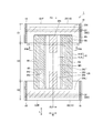
- FIG. 1 is a schematic front view of the absorbent article 1 according to the first embodiment.
- FIG. 2 is a schematic plan view of the absorbent article 1 according to the first embodiment.
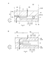
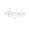
- FIG. 3 is a schematic cross-sectional view of the absorbent article according to the first embodiment.
- FIG. 4 is a schematic cross-sectional view of the absorbent article according to the first embodiment.
- FIG. 5 is a schematic cross-sectional view of the absorbent article according to the first embodiment.
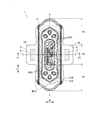
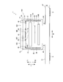
- FIG. 6 is a schematic plan view of the absorbent article 1 according to the second embodiment as viewed from the skin surface side.
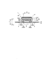
- FIG. 7 is a schematic cross-sectional view of the absorbent article 1 in the F7-F7 cross section in FIG. FIG.
- FIG. 8 is a schematic cross-sectional view of the absorbent article 1 in the F7-F7 cross section in FIG.
- FIG. 9 is a schematic cross-sectional view of the absorbent article according to the modified example.
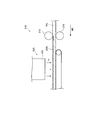
- FIG. 10 is a diagram for explaining a method for manufacturing a nonwoven fabric sheet.
- the absorbent article according to one aspect is an absorbent article provided with a non-woven fabric sheet having a hydrophobic ink, and in a plan view of the non-woven fabric sheet, the ink in which the hydrophobic ink is arranged on the non-woven fabric sheet.
- a region and a non-ink region in which the hydrophobic ink is not arranged are provided, and the thickness of the non-woven fabric sheet in the ink region is thinner than the thickness of the non-woven fabric sheet in the non-ink region.
- the non-woven fabric sheet in the ink region (hereinafter, the ink portion) is recessed from the non-woven fabric sheet in the non-ink region due to the difference in thickness, and a recess, that is, a space is formed in the non-woven fabric sheet.
- Air is easier to pass through space than a non-woven fabric sheet in which fibers are entwined. Therefore, by improving the air permeability around the ink portion by the concave portion, it is possible to supplement the air permeability that tends to be lowered by the hydrophobic ink. As a result, deterioration of the air permeability of the absorbent article can be suppressed.
- the hydrophobic ink is disposed on one side of the non-woven fabric sheet in the thickness direction, and is recessed in the thickness direction on one side of the non-woven fabric sheet with respect to the periphery of the ink region.
- a recess is provided. Since the recess is provided on one side where the hydrophobic ink is arranged, air that is difficult to pass through in the thickness direction due to the hydrophobic ink can pass through the recess in the plane direction.
- the side wall portion of the recess is around the ink region, air in the recess easily passes through the non-woven fabric sheet around the ink region through the side wall portion. As a result, deterioration of the air permeability of the absorbent article can be suppressed.
- the fiber density of the non-woven fabric sheet in the non-ink region is smaller than the fiber density of the non-woven fabric sheet in the ink region.
- the hydrophobic ink is arranged on one side of the non-woven fabric sheet in the thickness direction, and the thickness of the fiber on the one side of the non-woven fabric sheet is the other side of the non-woven fabric sheet. It is thicker than the thickness of the fiber.
- the hydrophobic ink is arranged on one side of the non-woven fabric sheet in the thickness direction, and the non-woven fabric sheet is pressed from the other side of the non-woven fabric sheet in the thickness direction. It has a squeezing part. On the other side where the non-woven fabric sheet is squeezed, the squeezing reduces the gaps between the fibers. For this reason, by arranging the hydrophobic ink on one side of the non-woven fabric sheet, which is less likely to reduce the gap between the fibers by pressing than on the other side, it is possible to easily pass air through the portion close to the hydrophobic ink, and the air permeability is deteriorated. Can be suppressed.
- the non-woven fabric sheet has an abutting sheet that contacts one side of the non-woven fabric sheet in the thickness direction, and the hydrophobic ink is arranged on the one side of the non-woven fabric sheet. Since the non-woven fabric sheet in the ink region is thinner than the thickness of the non-woven fabric sheet around the ink region, a gap (space) is likely to be formed between the non-woven fabric sheet and the contact sheet in the ink region. As a result, in the ink region, air can easily pass through the gap between the non-woven fabric sheet and the contact sheet, and deterioration of the air permeability of the absorbent article can be suppressed.
- the hydrophobic ink is arranged on one side of the non-woven fabric sheet that comes into contact with the contact sheet, the hydrophobic ink does not come into direct contact with the wearer's skin, and the hydrophobic ink adheres to the wearer's skin. Can be suppressed.
- a composite sheet including a contact sheet that comes into contact with one side of the nonwoven fabric sheet in the thickness direction and the nonwoven fabric sheet, and the composite sheet comes into contact with the nonwoven fabric sheet.
- the sheet has a shrinking region in which the sheet shrinks, at least a part of the ink region overlaps the shrinking region in the thickness direction, and in at least a part of the ink region, the nonwoven fabric sheet and the contact sheet Is non-woven.
- the non-woven fabric sheet and the contact sheet are easily separated from each other, and the space between the non-woven fabric sheet and the contact sheet can be widened. As a result, air can more easily pass through the gap between the non-woven fabric sheet and the contact sheet, and deterioration of the air permeability of the absorbent article can be suppressed. Further, since the ink region has higher rigidity than the non-ink region, wrinkles are relatively difficult to form in the ink region, and it is easy to maintain a state in which the non-woven fabric sheet and the contact sheet are in contact with each other. Even when the non-woven fabric sheet and the abutting sheet are in contact with each other, the breathability can be supplemented by the recesses formed in the non-woven fabric sheet.
- the non-woven fabric sheet has a folded-back portion in which the non-woven fabric sheet is folded back, and an opposed portion facing the folded-back portion and in contact with the folded-back portion, and the folded-back portion of the non-woven fabric sheet.
- At least a part of the hydrophobic ink is arranged at a position where it overlaps with the hydrophobic ink on the facing portion in the thickness direction.
- a larger space is likely to be formed in the region where at least a part of the hydrophobic ink in the folded portion overlaps with the hydrophobic ink in the facing portion in the thickness direction.
- air can more easily pass through the space between the folded-back portion and the facing portion, and deterioration of the air permeability of the absorbent article can be suppressed.
- the absorbent article is arranged on the non-skin surface side of the non-woven fabric sheet, and has an absorber that overlaps the ink region and the non-ink region in the thickness direction.
- the hydrophobic ink is arranged on the non-skin surface side of the non-woven fabric sheet, and the fiber density of the non-woven fabric sheet in the non-ink region is smaller than the fiber density of the non-woven fabric in the ink region. Since the hydrophobic ink is arranged on the non-skin surface side, the hydrophobic ink does not come into direct contact with the wearer's skin, and it is possible to prevent the hydrophobic ink from adhering to the wearer's skin.
- the excrement can easily come into contact with the non-woven fabric sheet in the non-ink region, and the start of drawing in the excrement can be accelerated.
- the fiber density of the ink region is high and the hydrophobic ink is arranged on the non-skin surface side of the non-woven fabric sheet, excrement can be drawn in the entire surface of the non-woven fabric sheet on the skin surface side. Therefore, it is possible to prevent a decrease in absorption speed.
- the excrement can move to the non-skin surface side of the non-woven fabric sheet via the non-ink region. , It is possible to suppress the deterioration of absorption performance.
- the absorbent article is arranged on the non-skin surface side of the non-woven fabric sheet, and has an absorber that overlaps the ink region and the non-ink region in the thickness direction.
- the hydrophobic ink is arranged on the skin surface side of the non-woven fabric sheet, and the fiber density of the non-woven fabric sheet in the non-ink region is smaller than the fiber density of the non-woven fabric sheet in the ink region. Since the non-woven fabric sheet is thick in the non-ink region, the excrement can easily come into contact with the non-woven fabric sheet in the non-ink region, and the start of drawing in the excrement can be accelerated.
- the excrement that has begun to be drawn in the non-ink region can be drawn by the capillary phenomenon in the portion on the non-skin surface side of the ink region having a high fiber density, it is possible to suppress a decrease in the speed of drawing the excrement. Since the hydrophobic ink is arranged on the skin surface side of the non-woven fabric sheet, it becomes difficult for excrement to return from the non-woven fabric sheet to the skin surface side in the ink region, and rewetback can be reduced.
- an absorber that is arranged on the non-skin surface side of the non-woven fabric sheet and that overlaps the ink region and the non-ink region in the thickness direction and abuts the wearer's skin. It has a skin surface sheet having a contact surface, and the non-woven fabric sheet is arranged between the skin surface sheet and the absorber in the thickness direction. Since the excrement can be quickly absorbed by the skin surface sheet, the excrement does not continue to remain on the contact surface of the skin surface sheet, so that the excrement can be prevented from leaking through the wearer's body. Further, since the skin surface sheet is present on the skin surface side of the non-woven fabric sheet having the hydrophobic ink, it is possible to prevent the hydrophobic ink from adhering to the wearer's skin.
- the thickness of the non-woven fabric sheet in the ink region is smaller than the thickness of the non-woven fabric sheet in the non-ink region with the boundary between the ink region and the non-ink region as a boundary. ..
- the side wall portion of the recess can be provided from the place where the hydrophobic ink is no longer arranged.
- the air permeability around the ink portion can be improved, so that the air permeability that tends to be lowered by the hydrophobic ink can be supplemented.
- deterioration of the air permeability of the absorbent article can be suppressed.
- the nonwoven fabric sheet according to one aspect is a nonwoven fabric sheet having hydrophobic ink and used for an absorbent article, and the hydrophobic ink is arranged on the nonwoven fabric sheet in a plan view of the nonwoven fabric sheet.
- An ink region and a non-ink region in which the hydrophobic ink is not arranged are provided, and the thickness of the non-woven fabric sheet in the ink region is thinner than the thickness of the non-woven fabric sheet in the non-ink region.
- the method for producing a nonwoven fabric sheet is a method for producing a nonwoven fabric sheet used for an absorbent article, in which a step of arranging a hydrophobic ink cured by ultraviolet rays on the nonwoven fabric and at least the hydrophobic ink are arranged. It has a step of irradiating the ink region with ultraviolet rays. In the ink region where the hydrophobic ink is arranged, the air between the device that irradiates the ultraviolet rays and the non-woven fabric is warmed by irradiating the ink with ultraviolet rays. The warmed air warms the air between the fibers of the non-woven fabric, which increases the bulk of the non-woven fabric.
- the hydrophobic ink is cured and dried by irradiating with ultraviolet rays.
- the fibers of the non-woven fabric are bonded to each other by the hydrophobic ink, and the fibers of the non-woven fabric are difficult to separate from each other.
- the bulk of the non-woven fabric sheet is unlikely to increase.
- the energy generated by the ultraviolet rays applied to the ink region is used for curing the hydrophobic ink, it is difficult to warm the air between the fibers of the non-woven fabric in the ink region.
- the thickness of the non-woven fabric sheet in the ink region can be made thinner than the thickness of the non-woven fabric sheet in the non-ink region. This makes it possible to manufacture a non-woven fabric sheet capable of suppressing deterioration of the air permeability of the absorbent article.
- the absorbent article is, for example, a pants-type disposable diaper, a tape-type disposable diaper, or a shorts-type sanitary napkin.
- the absorbent article of the embodiment is a pants-type disposable diaper.
- FIG. 1 is a schematic front view of the absorbent article 1 according to the present embodiment.
- FIG. 2 is a schematic plan view of the absorbent article 1 according to the present embodiment. The schematic plan view shown in FIG. 2 shows an stretched state in which the absorbent article 1 is stretched to a state in which wrinkles are not formed in a state where the side joint portion 18 described later is unfolded.
- FIG. 2 is a schematic plan view of the absorbent article 1 as viewed from the skin surface side T1.
- 3 to 5 are schematic cross-sectional views of the absorbent article according to the present embodiment.
- FIG. 3 is a schematic cross-sectional view taken along the F3-F3 cross section shown in FIG.
- FIG. 4A is a schematic cross-sectional view taken along the cross section of F4A-F4A shown in FIG. 4B and 4C are enlarged schematic cross-sectional views of the center sheet 41A and the absorber 50.
- FIG. 5A is an enlarged schematic cross-sectional view of the front exterior body 20.
- FIG. 5B is an enlarged schematic cross-sectional view of the side sheet 41B.
- the members are separated in the thickness direction, they are in contact with each other in the thickness direction in the actual product.
- the absorbent article 1 has a front-rear direction L, a width direction W, and a thickness direction.
- the anteroposterior direction L is defined by the direction extending to the anterior side and the posterior side of the body.
- the anteroposterior direction L is a direction extending anterior-posteriorly in the deployed absorbent article 1.
- the width direction W is a direction orthogonal to the front-rear direction L.
- the thickness direction T is orthogonal to both the front-rear direction L and the width direction W.
- the thickness direction T extends to the skin surface side T1 facing the wearer side and the non-skin surface side T2 on the side opposite to the skin surface side.
- the plane direction P indicates the direction of the plane along the front-rear direction L and the width direction W.
- the absorbent article 1 has a front side region S1, a rear side region S2, and an inseam region S3.
- the front side region S1 is a region facing the wearer's front waist circumference (abdomen).
- the rear side region S2 is an region facing the back waist (back) of the wearer, and includes an region on which the body (buttocks) is placed when worn.
- the inseam area S3 is located in the inseam of the wearer and is a region sandwiched between the front side area S1 and the rear side area S2.
- a side joint portion 18 may be provided in which the end portion of the front side region S1 in the width direction W and the end portion of the rear side region S2 in the width direction W are joined.
- the side joint portion 18 is defined by a portion in which the outer portion of the front side region S1 and the outer portion of the rear side region S2 are locked to each other.
- the absorbent article 1 in the state where the side joint 18 is formed, has a waist opening 16 through which the wearer's body is passed and a pair of legs into which the wearer's legs are inserted.
- the leg circumference opening 17 is formed.
- the waist opening 16 may be defined by the front edge S1F of the front region S1 and the trailing edge S2R of the rear region S2.
- FIG. 2 shows a state in which the joint at the side joint portion 18 is released and the absorbent article 1 is unfolded.
- the side joint portion 18 may extend along the front-rear direction L in each of the front exterior body 20 and the rear exterior body 30.
- the boundary between the front side region S1 and the inseam region S3 may be defined by the rear end edge of the side joint 18 provided on the front exterior body 20.
- the boundary between the rear side region S2 and the inseam region S3 may be defined by the front end edge of the side joint portion 18 provided on the rear exterior body 30.
- the inseam area S3 may be an area provided with the leg circumference opening 17.
- the outer portion in the present invention is a portion that occupies a certain range in the width direction W including the outer edge in the width direction W, and the outer edge is an outer edge in the width direction W.
- the inner portion in the present invention is a portion that occupies a certain range in the width direction W including the inner edge in the width direction W, and the inner edge is an inner edge in the width direction W.
- the front end portion and the rear end portion in the present invention are portions that occupy a certain range in the front-rear direction L including the edge in the front-rear direction L, and the front end edge and the rear end edge are edges in the front-rear direction L.
- the outer edge includes a front edge and a trailing edge, and the outer edge includes a front edge and a trailing edge.
- the absorbent article 1 may have an exterior body 15 and an absorbent main body 40.
- the exterior body 15 overlaps the absorbent body 40 in the thickness direction T.
- the exterior body 15 is arranged at least in the waist circumference area that covers the waist circumference of the wearer.
- the exterior body 15 may have at least a front exterior body 20 arranged in the front side region S1 and a rear exterior body 30 arranged at least in the rear side region S2.
- the front exterior body 20 may be arranged in the inseam area S3 in addition to the front side area S1, and the rear exterior body 30 may be arranged in the inseam area S3 in addition to the rear side area S2.
- the exterior body 15 may be a combination of the front exterior body 20 and the rear exterior body 30.
- the front exterior body 20 may be arranged on the non-skin surface side T2 of the absorbent body 40 in the front side region S1.
- the rear exterior body 30 may be separated from the front exterior body 20 in the front-rear direction L, and may be arranged on the non-skin surface side T2 of the absorbent main body 40 in the rear side region S2.
- the front exterior body 20 includes a first front seat 25 located on the non-skin surface side T2 of the absorbent body 40 and a second front seat 26 located on the non-skin surface side T2 of the first front seat 25. May have.
- the first front sheet 25 and the second front sheet 26 may be made of a non-woven fabric sheet.
- the rear exterior body 30 includes a first rear seat 35 located on the non-skin surface side T2 of the absorbent body 40 and a second rear seat 36 located on the non-skin surface side T2 of the first rear seat 35. And may have.
- the first rear sheet 35 and the second rear sheet 36 may be made of a non-woven fabric sheet.
- the exterior body 15 may have a waist elastic member WE having elasticity.
- the waist elastic member WE may be arranged so as to extend in the width direction W and may have elasticity in the width direction W.
- a plurality of waist elastic members WE may be arranged in the front-rear direction L.
- the waist elastic member WE may have a front waist elastic member 22 arranged on the front exterior body 20 and a rear waist elastic member 32 arranged on the rear exterior body 30.
- the front waist elastic member 22 may be arranged between the first front seat 25 and the second front seat 26 in the thickness direction T.
- the rear waist elastic member 32 may be arranged between the first rear seat 35 and the second rear seat 36 in the thickness direction T.
- the waist elastic member WE may be composed of, for example, a thread rubber that can be expanded and contracted in the width direction W, or an elastic sheet that can be expanded and contracted in the width direction W.
- the waist elastic member WE may be composed of, for example, the exterior body 15 itself made of a stretchable sheet.
- the waist elastic member WE of the present embodiment is made of thread rubber.
- the absorbent body 40 is arranged at least in the inseam area S3.
- the absorbent body 40 may be arranged over the anterior region S1, the posterior region S2 and the inseam region S3.
- the absorbent main body 40 is configured as a separate body from the front exterior body 20 and the rear exterior body 30, and may be joined to the front exterior body 20 and the rear exterior body 30 in the front side region S1 and the rear side region S2, respectively.
- the absorbent body 40 (absorbent article 1) has an absorber 50.
- the absorber 50 has at least an absorption core.
- the absorbent core contains an absorbent material that absorbs the liquid.
- the absorption core may include, for example, ground pulp or a highly absorbent polymer (SAP), or a mixture thereof.
- SAP highly absorbent polymer
- the absorption core is located at least in the inseam area S3.
- the absorption core may be arranged in the front side region S1 and may be arranged in the rear side region S2.
- the absorption core may extend from the front side region S1 to the rear side region S2 in the front-rear direction L.
- the absorber 50 may have a core wrap covering the absorption core.
- the core wrap may sandwich the absorbing core in the thickness direction T.
- the core wrap may be composed of, for example, a tissue or a non-woven fabric.
- the absorbent body 40 is composed of a skin surface sheet 41 located on the skin surface side T1 of the absorber 50, a liquid impermeable sheet 42 located on the non-skin surface side T2 of the absorber 50, and a liquid impermeable sheet 42. May also have a main body sheet 43 arranged on the non-skin surface side T2.
- the skin surface sheet 41 has a contact surface that comes into contact with the wearer's skin.
- the skin surface sheet 41 has a center sheet 41A that covers the center of the absorber 50 in the width direction W, and a pair of side sheets 41B that cover the outer portion of the center sheet 41A on the skin surface side T1 of the center sheet 41A. You can.
- the skin surface sheet 41 may have liquid permeability, and may be made of, for example, a non-woven fabric.
- the liquid opaque sheet 42 may have permeable and opaque properties, and may be made of, for example, a film.
- the main body sheet 43 may have hydrophobicity, and may be composed of, for example, a non-woven fabric having hydrophobicity.
- the absorbent article 1 includes a non-woven fabric sheet 10 made of a non-woven fabric.
- the non-woven fabric may be, for example, any of air-through non-woven fabric, spunbond non-woven fabric, spunlace non-woven fabric and the like.
- the non-woven fabric sheet 10 may be at least one of a first front sheet 25, a second front sheet 26, a first rear sheet 35, a second rear sheet 36, a center sheet 41A, a side sheet 41B, and a main body sheet 43. ..
- the non-woven fabric sheet 10 has the hydrophobic ink 2.
- the non-woven fabric sheet 10 is provided with an ink region IR in which the hydrophobic ink 2 is arranged and a non-ink region NR in which the hydrophobic ink 2 is not arranged.
- the hydrophobic ink 2 may be arranged (coated) by printing, for example.
- the method for printing the hydrophobic ink 2 may be flexographic printing or gravure printing.
- the hydrophobic ink 2 may contain a material that is cured by ultraviolet rays (UV). Examples of the material that is cured by ultraviolet rays include urethane acrylate, acrylic resin acrylate, and epoxy acrylate. Whether or not the hydrophobic ink 2 contains a material that is cured by ultraviolet rays can be measured by the following method.
- the hydrophobic ink 2 is collected from the non-woven fabric sheet 10 (ink portion 11) of the ink region IR using tweezers.
- the collected hydrophobic ink 2 is irradiated with infrared light using a Fourier transform infrared spectrophotometer (FT-IR), and the peak of the functional group is measured.
- FT-IR Fourier transform infrared spectrophotometer
- the ink region IR may have a first ink region IR1, a second ink region IR2, a third ink region IR3, and a fourth ink region IR4.
- the first ink region IR1 is provided on the non-woven fabric sheet 10 constituting the center sheet 41A.
- the second ink region IR2 and the third ink region IR3 are provided on the non-woven fabric sheet 10 constituting the side sheet 41B.
- the second ink region IR2 is provided in a portion where the three-dimensional gathers are arranged.
- the third ink region IR3 is provided in a portion where leg gathers are arranged.
- the fourth ink region IR4 is provided on the second front sheet 26 and the second rear sheet 36.
- the three-dimensional gather can stand on the skin side T1.
- the three-dimensional gather includes an upright portion that can stand up by contraction of the first elastic member 65 that has elasticity in the front-rear direction L, and a component member that is arranged on the side sheet 41B and the non-skin surface side T2 of the side sheet 41B. It may have a joint portion to be joined.
- the three-dimensional gather becomes a wall by standing up and prevents excrement from moving to the outside in the width direction W.
- the leg gathers are arranged outside the three-dimensional gathers in the width direction W, and contract due to the contraction of the second elastic member 66 having elasticity in the front-rear direction L. The leg gathers fit around the wearer's legs to prevent excrement from leaking out of the absorbent material.
- the non-woven fabric sheet 10 has an ink portion 11 composed of the non-woven fabric sheet 10 in the ink region IR and a non-ink portion 12 composed of the non-woven fabric sheet 10 in the non-ink region NR.
- the ink portion 11 may have an ink layer 11A in which the hydrophobic ink 2 is present and a non-ink layer 11B in which the hydrophobic ink 2 is not present.
- the ink layer 11A may be composed of a portion in which the non-woven fabric sheet 10 is impregnated with the hydrophobic ink and the hydrophobic ink 2 itself.
- hydroophobicity means a property that is difficult to be compatible with water or to retain water, and means, for example, a contact angle with ion-exchanged water of 80 ° or more.
- the contact angle with ion-exchanged water can be measured by the method described in "Measurement of initial contact angle" in JP-A-2005-324010.
- the hydrophobic ink 2 may be arranged on one side of the non-woven fabric sheet 10 in the thickness direction T. Therefore, the hydrophobic ink 2, that is, the ink layer 11A may be arranged on the non-skin surface side T2 of the non-woven fabric sheet 10 in the thickness direction T, or may be arranged on the skin surface side T1 of the non-woven fabric sheet 10 in the thickness direction T. It may be arranged. As shown in FIGS. 4B, 4C, and 5, a recess S recessed in the thickness direction T from the periphery of the ink region IR may be provided on one side of the non-woven fabric sheet 10.
- a recess S recessed in the thickness direction T from the side where the hydrophobic ink 2 is arranged may be provided.
- the recess S is recessed from the non-skin surface side T2 to the skin surface side T1.
- the recess S is recessed from the skin surface side T1 to the non-skin surface side T2.
- the recess S is recessed from the non-skin surface side T2 to the skin surface side T1 in the non-woven fabric sheet 10 on the skin surface side T1, and is not from the skin surface side T1 in the non-woven fabric sheet 10 on the non-skin surface side T2. It is dented to T2 on the skin side.
- the thickness Ti of the non-woven fabric sheet 10 (that is, the ink portion 11) in the ink region IR is thinner than the thickness Tn of the non-woven fabric sheet 10 (that is, the non-ink portion 12) in the non-ink region NR. ..
- the ratio (Tn / Ti) of the thickness Tn of the non-ink portion 12 to the thickness Ti of the ink portion 11 may be 0.85 or less. In this case, since the space formed by the recess S can be increased, the air permeability of the absorbent article can be improved.
- the thickness ratio (Tn / Ti) may be 0.2 or more.
- the thickness Ti of the ink portion 11 is 1.1 to 1.3 ⁇ m
- the thickness Tn of the non-ink portion 12 may be 1.6 to 1.8 ⁇ m. It should be noted that the total thickness of the ink portion 11 does not have to be larger than the total thickness of the non-ink portion 12.
- the thickness Ti of the non-woven fabric sheet 10 of the ink region IR is the non-woven fabric sheet of the non-ink region NR with the boundary between the ink region IR and the non-ink region NR (hereinafter referred to as an ink boundary) as a boundary. It may be thinner than the thickness Tn of 10.
- the side wall portion of the recess S has a portion not covered with the hydrophobic ink 2. It is preferable that the side wall portion of the recess S is not completely covered with the hydrophobic ink 2.
- the bottom of the recess S is composed of the ink layer 11A and does not have to be composed of the non-ink layer 11B. That is, only the ink layer 11A may form the bottom of the recess S.
- FIG. 3 and FIG. 4A the arrangement location of the hydrophobic ink 2 (ink layer 11A) is shown in an easy-to-understand manner, and the thickness of the hydrophobic ink 2 and the thickness of the non-woven fabric sheet 10 are not shown. It should be noted that there is no such thing.
- the thickness of the non-woven fabric sheet 10 can be measured by, for example, the following method. Using a digital microscope (for example, a digital microscope VHX-100 manufactured by KEYENCE CORPORATION), a magnified image is taken from a direction perpendicular to the cut surface of the non-woven fabric sheet 10. The enlarged image is an image enlarged to such that the entire thickness direction T of the non-woven fabric sheet 10 can be photographed, and the enlarged magnification is, for example, 20 to 50 times. The thickness of the non-woven fabric sheet 10 is measured based on the obtained enlarged image. The enlarged image may be image-processed so that the thickness can be easily measured. The average value of the thickness measured at three separate cut surfaces in each of the smooth portion with the non-ink region NR (that is, the portion not affected by pressing and printing, etc.) and the ink region IR. The thickness of the non-woven fabric sheet 10 is set.
- a digital microscope for example, a digital microscope VHX-100 manufactured by KEYENCE CO
- the fiber density of the non-woven fabric sheet 10 in the non-ink region NR may be smaller than the fiber density of the non-woven fabric sheet 10 in the ink region IR. Therefore, the fiber density of the non-ink layer 11B of the ink portion 11 may be smaller than the fiber density of the non-ink portion 12.
- the fiber density of the non-woven fabric sheet 10 can be measured by, for example, the following method. Specifically, when measuring the fiber densities of the respective non-woven fabric sheets 10 in the ink region IR and the non-ink region NR, the following methods can be used.
- the ink portion 11 and the non-ink portion 12 are cut out to a size of 10 mm ⁇ 10 mm and used as a sample.
- the cut surface parallel to the thickness direction T of the sample is magnified and observed using a scanning electron microscope (manufactured by JEOL Ltd .: JCM-5100). The magnification is such that the cross section of 30 to 60 fibers can be measured in one screen (example: 150 to 500 times).
- the number of cross sections of the fibers is measured in each of the ink portion 11 and the non-ink portion 12. Specifically, the number of cross sections of the cut fiber is counted on the cut surface having a predetermined area.
- the ink layer 11A and the non-ink layer 11B are separated in the thickness direction T, and then the cross section of the fibers in the non-ink layer 11B. Measure the number of.
- the non-woven fabric sheet 10 is formed by laminating a plurality of fiber layers, the number of cross sections of the cut fibers in the same fiber layer in the ink portion 11 and the non-ink portion 12 is counted.
- the number of cross sections of the obtained fibers is converted into the number of cross sections of the fibers around 1 mm 2 and this is defined as the fiber density (book / mm 2 ). The measurement is performed at three places, and the average value of the measured values is taken as the fiber density of the sample.
- the number of fibers per unit area in the cross section parallel to the thickness direction T is used as the fiber density
- the number of fibers per unit volume may be used as the fiber density.
- the number of fibers per unit volume can be obtained by, for example, analysis by X-ray CT. Although the numerical values are different between the fiber density per unit area and the fiber density per unit volume, they are the same in the relative comparison of fiber densities (example: comparison of size).
- the fiber density of the non-woven fabric sheet 10 on one side on which the hydrophobic ink 2 is arranged may be smaller than the fiber density on the surface of the non-woven fabric sheet 10 on the other side on which the hydrophobic ink 2 is not arranged.
- the gap between the fibers on the side where the hydrophobic ink 2 is arranged can be increased, air can easily pass through on the side where the hydrophobic ink 2 is arranged, and deterioration of air permeability can be suppressed.
- the fiber density in this case can be measured by the following method.
- One side of the non-woven fabric sheet 10 on which the hydrophobic ink 2 is arranged (for example, the surface of the non-skin surface side T2 of the skin surface sheet 41 in FIG. 4) and the other side on which the hydrophobic ink 2 is not arranged.
- Photographed with an electron microscope or a microscope for example, (VHX-2000 manufactured by KEYENCE) for each of the surfaces of the non-woven fabric sheet 10 (for example, the surface of the skin surface sheet 41 on the skin surface side T1 in FIG.
- a magnified image of the fiber is obtained.
- the area of the fiber per unit area in the image is measured. From this, the area ratio of the fiber is calculated.
- the area ratio of the fibers can be regarded as the fiber density, and the fiber density of the non-woven fabric sheet 10 on one side and the fiber density of the non-woven fabric sheet 10 on the other side can be compared.
- the fiber thickness of the non-woven fabric sheet 10 on one side on which the hydrophobic ink 2 is arranged may be thicker than the fiber thickness on the non-woven fabric sheet 10 on the other side on which the hydrophobic ink 2 is not arranged. Therefore, the thickness of the fibers of the non-ink layer 11B close to the ink layer 11A or the ink layer 11A may be thicker than the thickness of the fibers of the non-ink layer 11B far from the ink layer 11A.
- the thickness of the fiber can be measured by, for example, the following method.
- One side of the non-woven fabric sheet 10 on which the hydrophobic ink 2 is arranged (for example, the surface of the non-skin surface side T2 of the skin surface sheet 41 in FIG. 4) and the other side on which the hydrophobic ink 2 is not arranged.
- Each of the surface of the non-woven fabric sheet 10 (for example, the surface of the skin surface sheet 41 on the skin surface side T1 in FIG. 4) is measured a plurality of times (the number is about 100).
- the average value of the measured fiber diameters is taken as the fiber thickness. Therefore, it can be determined that the larger the average value of the fiber diameters, the thicker the fibers.
- the fiber thickness of the skin surface side T1 may be thicker than the fiber thickness of the non-skin surface side T2 in the non-ink portion 12.
- the non-woven fabric sheet 10 may have a pressed portion (not shown) pressed in the thickness direction T.
- the ink region IR does not have to be provided with a pressing portion. Therefore, the non-woven fabric sheet 10 may be provided with a squeezed portion only in the non-ink region NR.
- a pressing portion may be provided in the ink region IR.
- the non-woven fabric sheet 10 may have a squeezed portion squeezed from the other side on which the hydrophobic ink 2 is not arranged.
- the non-woven fabric sheet 10 may have a squeezed portion pressed from the side on which the hydrophobic ink 2 is arranged.
- the absorbent article 1 may have a composite sheet 13.
- the composite sheet 13 may include a non-woven fabric sheet 10 on which the hydrophobic ink 2 is arranged and a contact sheet that abuts on one side of the non-woven fabric sheet 10 in the thickness direction T.
- the hydrophobic ink 2 is arranged on the first sheet 13A.
- the non-woven fabric sheet 10 is made, and the second sheet 13B may be a contact sheet that comes into contact with one side of the non-woven fabric sheet 10 in the thickness direction T.
- the first sheet 13A and the second sheet 13B may be joined by the joint portion B.
- the composite sheet 13 may have a shrinkage region CR in which the first sheet 13A (nonwoven fabric sheet 10) and the second sheet 13B (contact sheet) contract.
- the first sheet 13A and the second sheet 13B may be contracted by the elastic members (for example, waist elastic member WE, first elastic member 65, second elastic member 66, etc.) included in the composite sheet 13.
- the elastic members for example, waist elastic member WE, first elastic member 65, second elastic member 66, etc.
- the first sheet 13A and the second sheet 13B may shrink.
- the ink region IR may overlap with the shrinkage region CR in the thickness direction T.
- the first sheet 13A and the second sheet 13B may be non-bonded to at least a part of the ink region IR. Therefore, the joint portion B for joining the sheets does not have to overlap with the ink region IR in the thickness direction T. All of the ink region IRs may be unbonded.
- the non-woven fabric sheet 10 may have a folded-back portion 10f in which the non-woven fabric sheet 10 is folded back, and an opposed portion 10c facing the folded-back portion 10f and in contact with the folded-back portion 10f.
- the facing portion 10c may be a portion where the non-woven fabric sheet 10 is not folded back.
- at least a part of the hydrophobic ink 2 of the folded-back portion 10f may be arranged at a position overlapping the hydrophobic ink 2 of the facing portion 10c in the thickness direction T.
- the absorber 50 may be arranged on the non-skin surface side T2 of the non-woven fabric sheet 10.
- the absorber 50 may overlap the ink region IR and the non-ink region NR in the thickness direction T.
- the hydrophobic ink 2 may be arranged on the non-skin surface side T2 of the non-woven fabric sheet 10. Therefore, the ink layer 11A may be arranged on the non-skin surface side T2 of the non-woven fabric sheet 10.
- the fiber density of the non-woven fabric sheet 10 in the non-ink region NR may be smaller than the fiber density of the non-woven fabric sheet 10 in the ink region IR.
- the fiber density of the non-woven fabric sheet 10 in the non-ink region NR near the ink boundary between the ink region IR and the non-ink region NR (for example, within a range of 5 mm from the ink boundary) and the non-ink region separated from the ink boundary by a predetermined distance.
- the difference from the fiber density of the non-woven fabric sheet 10 of NR may be within 5%.
- the fiber density of the non-woven fabric sheet 10 in the non-ink region NR does not change significantly in a predetermined range from the vicinity of the ink boundary, so that the air permeability and the absorption performance can be stabilized in the non-ink region NR.
- the fiber density of the non-woven fabric sheet 10 in the ink region IR near the ink boundary (for example, within a range of 5 mm from the ink boundary) and the ink region IR (for example, in the range of 10 mm to 15 mm from the ink boundary) separated from the ink boundary by a predetermined distance. ) May be within 5% of the fiber density of the non-woven fabric sheet 10.
- the fiber density of the non-woven fabric sheet 10 in the ink region IR does not change significantly in a predetermined range from the vicinity of the ink boundary, it is possible to prevent the air permeability and absorption performance from being significantly deteriorated in the ink region IR.
- the non-woven fabric sheet 10 in the ink region IR is recessed from the non-woven fabric sheet 10 in the non-ink region NR due to the difference in thickness between the ink portion 11 and the non-ink portion 12. is there. Due to this difference in thickness, a recess S, that is, a space is formed in the non-woven fabric sheet 10.
- the gap between the fibers becomes small or easily closed by the hydrophobic ink 2. Therefore, as shown in FIG. 4B, the amount of air passing from the ink portion 11 to the recess S is reduced.
- the gap between the fibers in the non-ink region NR becomes large.
- air can easily pass through in the non-ink region NR around the ink region IR, and by improving the air permeability around the ink portion 11, it is possible to supplement the air permeability that is easily reduced by the hydrophobic ink 2.
- the fiber thickness of the non-woven fabric sheet 10 on one side (ink layer 11A side) on which the hydrophobic ink 2 is arranged is the non-woven fabric on the other side (non-ink layer 11B side) on which the hydrophobic ink 2 is not arranged.
- the gap between the fibers on one side can be increased.
- air can easily pass through the portion close to the hydrophobic ink 2, and deterioration of air permeability can be suppressed.
- the non-woven fabric sheet 10 has a squeezed portion squeezed from the other side (non-ink layer 11B side) on which the hydrophobic ink 2 is not arranged, the gap between the fibers is reduced by squeezing on the other side. .. Therefore, by arranging the hydrophobic ink 2 on one side of the non-woven fabric sheet 10 in which the gap between the fibers is less likely to be reduced by pressing than on the other side, air can easily pass through the portion close to the hydrophobic ink 2 and air is ventilated. It can suppress the deterioration of sexuality.
- the thickness Ti of the non-woven fabric sheet 10 in the ink region IR is thinner than the thickness Tn of the non-woven fabric sheet 10 in the non-ink region NR with the ink boundary as a boundary, the thickness of the non-woven fabric sheet 10 is near the ink boundary. You can change the ink. As a result, the side wall portion of the recess S can be provided from the place where the hydrophobic ink 2 is no longer arranged, so that the air permeability that is easily lowered by the hydrophobic ink 2 can be supplemented. As a result, deterioration of the air permeability of the absorbent article can be suppressed.
- the recess S causes the first sheet 13A and the second sheet 13B to be connected to each other. Gap (space) is likely to be formed between them.
- air can easily pass through the space between the first sheet 13A and the second sheet 13B, and deterioration of the air permeability of the absorbent article 1 can be suppressed.
- the hydrophobic ink 2 since the hydrophobic ink 2 is not exposed, the hydrophobic ink 2 does not come into direct contact with the wearer's skin, and the hydrophobic ink 2 can be prevented from adhering to the wearer's skin.
- the first sheet 13A and the second sheet 13B are not joined in at least a part of the ink region IR.
- the first sheet 13A and the second sheet 13B can be separated from each other in the thickness direction T. is there.
- the first sheet 13A and the second sheet 13B are easily separated from each other, and the first sheet 13A and the second sheet 13B are separated from each other. You can expand the space.
- the ink region IR has higher rigidity than the non-ink region NR, wrinkles are relatively difficult to form in the ink region IR, and the first sheet 13A and the second sheet 13B are in contact with each other. Easy to maintain. Even when the first sheet 13A and the second sheet 13B are in contact with each other, the recess S formed in the first sheet 13A can supplement the air permeability.
- At least a part of the hydrophobic ink 2 of the folded-back portion 10f is arranged at a position where it overlaps with the hydrophobic ink 2 of the facing portion 10c in the thickness direction T, so that the ink portions 11 overlap each other.
- a larger space is likely to be formed.
- air can more easily pass through the space between the folded-back portion 10f and the facing portion 10c, and deterioration of the air permeability of the absorbent article 1 can be suppressed.
- the excrement E drawn into the non-ink portion 11B is easily drawn into the non-ink portion 12 due to the capillary phenomenon, so that the absorption speed Can be prevented from decreasing.
- the excrement E absorbed by the absorber 50 is less likely to return to the skin surface side T1 due to the ink layer 11A, so that rewetback can be reduced.
- FIG. 6 is a schematic plan view of the absorbent article 1 as viewed from the skin surface side.
- 7 and 8 are schematic cross-sectional views of the absorbent article 1 in the F7-F7 cross section in FIG.
- FIG. 8 is a diagram for explaining the arrangement relationship of each member, and each member is shown in a simplified manner.
- the embodiment will be described by taking a sanitary napkin as an example as an absorbent article according to the second embodiment.
- the absorbent article 1 is not limited to a sanitary napkin, but may be a panty liner, a pad for light incontinence, or the like.
- the absorbent article 1 may be used by being fixed to an article worn by the user. The description of the same part as that of the first embodiment will be omitted.
- the absorbent article 1 has a pair of wings 1W.
- the pair of wings 1W extend outward in the width direction from the outer edge of the absorber 50 (absorption core) in the width direction W. Therefore, it extends from the central portion in the front-rear direction L to both outer sides in the width direction W. Further, the pair of wings 1W can be folded back when the absorbent article 1 is used.
- the absorbent article 1 has a skin surface sheet 41, a second sheet 45, an absorbent body 50, a liquid permeable sheet 42, and a backside sheet 47.
- the skin surface sheet 41, the second sheet 45, the absorber 50, the backside sheet 47, and the liquid impermeable sheet 42 are laminated.
- the skin surface sheet 41, the second sheet 45, the absorber 50, the liquid permeable sheet 42 and the back side sheet 47 are joined and fixed by a joint portion.
- an adhesive HMA such as a hot melt adhesive can be used.
- the second sheet 45 may be arranged between the skin surface sheet 41 and the absorber 50.
- the second sheet 45 is a non-woven fabric sheet, and examples thereof include an air-through non-woven fabric, a spunbonded non-woven fabric, and a spunlaced non-woven fabric.
- the skin surface sheet 41 and the second sheet 45 are wound together so as to wrap the end portion in the width direction W in an integrated state of being bonded by the adhesive HMA.
- the skin surface sheet 41 is joined and fixed at the joint portion 84 on the non-skin surface side of the absorber 50 by the adhesive HMA.
- the main body 80 in which the skin surface sheet 41, the second sheet 45, and the absorber 50 are integrated is configured.
- the adhesive HMA that joins and fixes each member it is not necessary to apply the adhesive to the entire area.
- the pair of main body joints 85 described later in the main body 80 can be used. The flexibility of the outside of the width direction W can be ensured, and the touch can be improved.
- the main body joint portion 85 joins the main body portion 80 and the non-skin side sheet.
- the non-skin surface side surface of the main body 80 and the skin surface side surface of the back side sheet 47 are joined at the main body joint 85 using an adhesive such as hot melt.
- the main body joint 85 has a continuous shape along the front-rear direction L.
- the main body joint 85 is arranged at both ends in the width direction W.
- the non-skin side sheet may be only the liquid permeable sheet 42, or may be a combination of the liquid permeable sheet 42 and the back side sheet 47.
- the skin surface sheet 41 may have a pair of first folded portions 2h whose side ends on both sides in the width direction W are folded back to the non-skin surface side T2.
- the pair of first folded portions 2h are joined to the back side sheet 47 by the main body joining portion 85.
- the widthwise tips of the pair of first folded portions 2h may be located inside the widthwise direction W with respect to the outer edge of the main body joint 85. As a result, the tip (edge) of the skin surface sheet 41 (first folded portion 2h) is not exposed. Therefore, since the tip of the skin surface sheet 41 does not hit the wearer's skin, deterioration of the touch can be suppressed.
- the second sheet 45 may have a pair of second folded portions 3h whose side ends on both sides in the width direction W are folded back to the non-skin surface side T2.
- the backside sheet 47 is a hydrophobic sheet member, and examples thereof include an air-through non-woven fabric, a spunbonded non-woven fabric, and a spunlaced non-woven fabric.
- a central adhesive portion 8 to which an adhesive is applied may be provided on the non-skin side surface of the absorbent article 1 (that is, the non-skin side surface of the liquid impermeable sheet 42).
- the absorbent article 1 is fixed to the underwear or the like by being attached to the skin side surface of the worn article such as underwear.
- a wing adhesive portion 9 is provided on the non-skin side surface (non-skin surface side T2 of the liquid impermeable sheet 42) in the thickness direction T of each wing 1W.
- the absorber 50 is a member that absorbs excrement and holds it inside.
- the absorber 50 may have a first absorption core 51A, a second absorption core 51B, and a cover sheet 52.
- the first absorption core 51A may have the same configuration as the absorption core of the first embodiment.
- the second absorbent core 51B may be a sheet-like member in which a highly absorbent polymer (so-called SAP) or the like, which is a liquid absorbent granular material, is sandwiched between a liquid permeable sheet such as a tissue from the skin side surface and the non-skin side surface, respectively. ..
- SAP highly absorbent polymer
- the cover sheet 52 is a liquid-permeable sheet member, and examples thereof include an air-through non-woven fabric, a spunbonded non-woven fabric, and a spunlaced non-woven fabric.
- the cover sheet 52 may be sandwiched between the first absorption core 51A and the second absorption core 51B.
- the second sheet 45 may have the hydrophobic ink 2.
- the excrement can be quickly absorbed by the skin sheet 41, so that the excrement does not continue to remain on the contact surface of the skin sheet 41. Therefore, it is possible to prevent excrement from leaking through the wearer's body.
- the skin surface sheet 41 is present on the skin surface side T1 of the second sheet 45 having the hydrophobic ink 2, it is possible to prevent the hydrophobic ink 2 from adhering to the wearer's skin.
- the absorbent article 1 may be designed by the hydrophobic ink 2.
- the hydrophobic ink 2 may be arranged on the skin surface side T1 of the second sheet 45.
- the design can be made easier to see as compared with the case where the hydrophobic ink 2 is arranged on the non-skin surface side T2 of the second sheet 45.
- FIG. 9 is a schematic cross-sectional view of the absorbent article according to the modified example.
- FIG. 9 is an enlarged schematic cross-sectional view of the center sheet 41A and the absorber 50, similarly to FIGS. 4B and 4C. In the following, the same description as already described will be omitted.
- the hydrophobic ink 2 may be arranged on the skin surface side T1 of the non-woven fabric sheet 10.
- the excrement E can easily come into contact with the non-woven fabric sheet 10 in the non-ink region NR, and the start of drawing in the excrement E can be accelerated. Further, the excrement E excreted in the ink region IR easily touches the non-ink portion 12 which is the side wall of the recess S, and can reach the absorber 50 via the non-ink portion 12.
- the excrement E that has begun to be drawn in the non-ink region NR is collected in the ink portion 11 having a high fiber density. Since it can be pulled in by the capillary phenomenon, it is possible to suppress a decrease in the speed at which the excrement E is drawn. Further, since the hydrophobic ink 2 is arranged on the skin surface side T1 of the non-woven fabric sheet 10, it becomes difficult for excrement to return from the non-woven fabric sheet to the skin surface side in the ink region IR, and rewetback can be reduced.
- the hydrophobic ink 2 is arranged on the bottom surface of the recess S, so that the hydrophobic ink does not easily adhere to the wearer's skin. Can be done.
- FIG. 10 is a diagram for explaining a method for manufacturing a nonwoven fabric sheet.
- the direction in which the component parts are conveyed in the manufacturing process is shown as the transfer direction MD.
- the non-woven fabric 10C is transported in the transport direction MD.
- the non-woven fabric 10C may be a continuous sheet in which any of the constituent members composed of the above-mentioned non-woven fabric is continuous.
- the hydrophobic ink 2 is placed on the non-woven fabric 10C.
- the hydrophobic ink may be arranged by applying the hydrophobic ink 2 to the non-woven fabric 10C using the coating device 210.
- the method of applying the hydrophobic ink 2 may be flexographic printing or gravure printing.
- the coating device 210 may be composed of a pair of upper and lower rolls. By passing the non-woven fabric 10C through the gap between the rolls, the hydrophobic ink 2 on at least one roll may be applied to the non-woven fabric 10C.
- the hydrophobic ink 2 is an ink that is cured by ultraviolet rays (UV). Therefore, the hydrophobic ink 2 may contain a material that is cured by ultraviolet rays.
- UV ultraviolet rays
- Step S20 is a step of irradiating at least the ink region IR in which the hydrophobic ink 2 is arranged with ultraviolet rays.
- the irradiation device 220 can be used to irradiate the ink region IR with ultraviolet rays.
- the air between the irradiation device 220 and the non-woven fabric 10C is warmed by irradiating with ultraviolet rays. Since the air between the fibers of the non-woven fabric is warmed by the warmed air, the bulk of the non-woven fabric 10C increases.
- the hydrophobic ink is cured and dried by irradiating with ultraviolet rays.
- the hydrophobic ink 2 joins the fibers of the non-woven fabric 10C to each other, making it difficult for the fibers of the non-woven fabric 10C to separate from each other.
- the bulk of the non-woven fabric sheet 10 is unlikely to increase.
- the energy generated by the ultraviolet rays applied to the ink region IR is used for curing the hydrophobic ink, it is difficult to warm the air between the fibers of the non-woven fabric 10C in the ink region IR.
- the thickness of the non-woven fabric 10C in the ink region IR can be made thinner than the thickness of the non-woven fabric 10C in the non-ink region NR.
- the non-ink region NR around the ink region IR may be irradiated with ultraviolet rays.
- the ultraviolet energy may be converted into heat energy to further warm the air between the fibers of the non-woven fabric.
- the bulk of the non-woven fabric 10C is further increased in the non-ink region NR.
- the irradiation device 220 may irradiate not only ultraviolet rays but also infrared rays. As a result, the non-woven fabric 10C can be heated, so that the air between the fibers can be further heated. Further, not only the irradiation device 220 but also the heating device may be used to heat the air between the fibers of the non-woven fabric 10C. As a result, the bulk of the non-woven fabric 10C in the non-ink region NR can be further increased.
- the hydrophobic ink 2 may be arranged on the surface on the side where the fiber thickness is thick.
- the thickness of the fiber on the side where the hydrophobic ink 2 is arranged may be thicker than the thickness of the fiber on the side where the hydrophobic ink 2 is not arranged.
- the thicker the fiber when ultraviolet rays are irradiated from the surface side on which the hydrophobic ink 2 is arranged, the thicker the fiber, the larger the volume, so that the depth of the recess S can be increased. it can.
- by improving the air permeability around the ink portion 11 by the recess S it is possible to supplement the air permeability that tends to be lowered by the hydrophobic ink 2.
- step S10 the bulk of the non-woven fabric 10C may be reduced by being sandwiched between the pair of rolls by being applied by the pair of rolls.
- step S20 the bulk of the non-woven fabric sheet 10 may be restored in the non-ink region NR.
- the bulk of the non-woven fabric sheet 10 does not have to recover up to the stage prior to step S10.
- the hydrophobic ink 2 is an ink that is cured by ultraviolet rays
- the hydrophobic ink can be dried by irradiating with ultraviolet rays.
- the drying time can be shortened as compared with the case of drying without irradiating with ultraviolet rays.
- it is not necessary to lengthen the transport path for drying the size of the manufacturing apparatus can be suppressed, and the manufacturing time can be shortened.
- the absorbent article 1 can be produced by using the produced nonwoven fabric sheet 10.
- the hydrophobic ink 2 is arranged on the skin surface side T1 of the second sheet 45, but the present invention is not limited to this.
- the hydrophobic ink 2 may be arranged on the non-skin surface side T2 of the second sheet 45.
- a recess S space
- the absorber 50 is likely to bend in a convex shape along the wearer's body in accordance with the movement of the wearer. can do.
- the absorber 50 becomes difficult to separate from the wearer's body, and leakage of excrement can be reduced.
- each modification, and the configuration of the absorbent article according to the other embodiment can be combined as appropriate.
- a napkin such as the second embodiment
- a non-woven fabric sheet having the hydrophobic ink 2 can be used as in the first embodiment.
Landscapes
- Health & Medical Sciences (AREA)
- Epidemiology (AREA)
- Engineering & Computer Science (AREA)
- Biomedical Technology (AREA)
- Heart & Thoracic Surgery (AREA)
- Vascular Medicine (AREA)
- Life Sciences & Earth Sciences (AREA)
- Animal Behavior & Ethology (AREA)
- General Health & Medical Sciences (AREA)
- Public Health (AREA)
- Veterinary Medicine (AREA)
- Absorbent Articles And Supports Therefor (AREA)
Abstract
【課題】通気性の悪化を抑制できる吸収性物品、不織布シート、及び不織布シートの製造方法を提供する。 【解決手段】 吸収性物品1は、疎水性インク2を有する不織布シート10を備える。不織布シート10の平面視において、不織布シート10には、疎水性インク2が配置されているインク領域IRと、疎水性インク2が配置されていない非インク領域NRと、が設けられている。インク領域IRの不織布シート10の厚さTiは、非インク領域NRの不織布シート10の厚さTnよりも薄い。
Description
本発明は、吸収性物品、不織布シート、及び不織布シートの製造方法に関する。
従来、顔料又は染料により構成されるインクを有する不織布シートを備えた吸収性物品が広く知られている。例えば、特許文献1では、排泄物を隠蔽するために、インクによって不織布シートを寒色系に着色している。
ここで、疎水性インクを不織布シートに配置するケースでは、疎水性インクによって不織布シートを構成する繊維間の隙間が狭くなったり、当該隙間が塞がれたりすることがある。この場合、疎水性インクが配置されている部分の通気性が悪化するため、当該不織布シートを備えた吸収性物品を着用した場合、ムレが生じ易くなる虞がある。
そこで、本発明は、上述した課題を解決するためになされたものであり、通気性の悪化を抑制できる吸収性物品、不織布シート、及び不織布シートの製造方法を提供することを目的とする。
一態様に係る吸収性物品は、疎水性インクを有する不織布シートを備えた吸収性物品であって、前記不織布シートの平面視において、前記不織布シートには、前記疎水性インクが配置されているインク領域と、前記疎水性インクが配置されていない非インク領域と、が設けられており、前記インク領域の前記不織布シートの厚さは、前記非インク領域の前記不織布シートの厚さよりも薄い。
一態様に係る不織布シートは、疎水性インクを有し、かつ吸収性物品に用いられる不織布シートであって、前記不織布シートの平面視において、前記不織布シートには前記疎水性インクが配置されているインク領域と、前記疎水性インクが配置されていない非インク領域と、が設けられており、前記インク領域の前記不織布シートの厚さは、前記非インク領域の前記不織布シートの厚さよりも薄い。
一態様に係る不織布シートの製造方法は、吸収性物品に用いられる不織布シートの製造方法であって、紫外線により硬化する疎水性インクを不織布に配置する工程と、少なくとも前記疎水性インクが配置されたインク領域に対して、紫外線を照射する工程と、を有する。
疎水性インクが配置されているインク領域では、紫外線を照射することにより、紫外線を照射する装置から不織布までの間の空気が温められる。温められた空気によって不織布の繊維間の空気が温められるため、不織布の嵩が増加する。しかしながら、インク領域では、紫外線を照射することにより疎水性インクが硬化し、乾燥する。これにより、疎水性インクによって不織布の繊維どうしが接合されて不織布の繊維どうしが離れ難くなる。これにより、インク領域の不織布の繊維間の空気が暖められたとしても、不織布シートの嵩が増加し難い。加えて、インク領域に照射された紫外線によるエネルギーは、疎水性インクの硬化にエネルギーが用いられるため、インク領域の不織布の繊維間の空気が暖められ難い。その結果、インク領域の不織布シートの厚さを非インク領域の不織布シートの厚さよりも薄くすることができる。これにより、吸収性物品の通気性の悪化を抑制できる不織布シートを製造することができる。
(1)実施形態の概要
本明細書及び添付図面の記載により、少なくとも以下の事項が明らかとなる。
本明細書及び添付図面の記載により、少なくとも以下の事項が明らかとなる。
一態様に係る吸収性物品は、疎水性インクを有する不織布シートを備えた吸収性物品であって、前記不織布シートの平面視において、前記不織布シートには、前記疎水性インクが配置されているインク領域と、前記疎水性インクが配置されていない非インク領域と、が設けられており、前記インク領域の前記不織布シートの厚さは、前記非インク領域の前記不織布シートの厚さよりも薄い。
これにより、厚さの違いによって、インク領域の不織布シート(以下、インク部)は、非インク領域の不織布シートよりも凹んだ状態であり、不織布シートに凹部、すなわち空間が形成される。空気は、繊維が絡み合った不織布シートよりも空間を通り抜け易い。従って、凹部によってインク部の周辺の通気性を向上させることで、疎水性インクによって低下し易い通気性を補うことができる。その結果、吸収性物品の通気性の悪化を抑制できる。
好ましい一態様によれば、前記疎水性インクは、厚さ方向における前記不織布シートの一方側に配置されており、前記不織布シートの一方側において、前記インク領域の周囲よりも前記厚さ方向に凹んでいる凹部が設けられている。疎水性インクが配置されている一方側において凹部が設けられているため、疎水性インクによって厚さ方向に通り抜け難い空気が、凹部内を平面方向に通り抜けることができる。加えて、凹部の側壁部分は、インク領域の周囲であるため、凹部内の空気が、側壁部分を通じてインク領域の周囲の不織布シート内を通り抜け易くなる。その結果、吸収性物品の通気性の悪化を抑制できる。
好ましい一態様によれば、前記非インク領域の前記不織布シートの繊維密度は、前記インク領域の前記不織布シートの繊維密度よりも小さい。これにより、非インク領域の繊維間の隙間が大きいため、インク領域の周囲の非インク領域において空気が通り抜け易くなり、インク部の周辺の通気性を向上させることで、疎水性インクによって低下し易い通気性を補うことができる。
好ましい一態様によれば、前記疎水性インクは、前記厚さ方向における前記不織布シートの一方側に配置されており、前記不織布シートの前記一方側の繊維の太さは、前記不織布シートの他方側の繊維の太さよりも太い。不織布シートの一方側(すなわち、疎水性インクが配置されている側)の繊維の太さを太くすることで、当該一方側の繊維間の隙間を大きくすることができる。これにより、疎水性インクに近い部分で空気を通り抜け易くでき、通気性の悪化を抑制できる。
好ましい一態様によれば、前記疎水性インクは、前記厚さ方向における前記不織布シートの一方側に配置されており、前記不織布シートは、前記不織布シートの他方側から前記厚さ方向に圧搾された圧搾部を有する。不織布シートが圧搾された他方側では、圧搾によって繊維間の隙間が小さくなってしまう。このため、他方側よりも、圧搾によって繊維間の隙間が小さくなり難い不織布シートの一方側に疎水性インクを配置することで、疎水性インクに近い部分で空気を通り抜け易くでき、通気性の悪化を抑制できる。
好ましい一態様によれば、前記厚さ方向における前記不織布シートの一方側と当接する当接シートを有し、前記疎水性インクは、前記不織布シートの前記一方側に配置されている。インク領域の不織布シートは、インク領域の周囲の不織布シートの厚さよりも薄いため、インク領域において不織布シートと当接シートとの間に隙間(空間)が形成され易い。その結果、インク領域では、不織布シートと当接シートと間の隙間を空気が通り抜け易くなり、吸収性物品の通気性の悪化を抑制できる。また、疎水性インクが、当接シートと当接する不織布シートの一方側に配置されているため、疎水性インクが着用者の肌に直接接触せず、着用者の肌に疎水性インクが付着することを抑制できる。
好ましい一態様によれば、前記厚さ方向における前記不織布シートの一方側と当接する当接シートと、前記不織布シートとを含む複合シートを有し、前記複合シートは、前記不織布シートと前記当接シートとが収縮する収縮領域を有し、前記インク領域の少なくとも一部は、前記収縮領域と前記厚さ方向において重なっており、前記インク領域の少なくとも一部では、前記不織布シートと前記当接シートとが非接合である。これにより、インク領域の少なくとも一部では、不織布シートと当接シートとが接合されていないため、不織布シートと当接シートとが厚さ方向に離れることが可能である。インク領域の少なくとも一部では、収縮領域における収縮によって皺が形成された場合、不織布シートと当接シートとが離れやすくなり、不織布シートと当接シートとの間の空間を広げることができる。その結果、不織布シートと当接シートと間の隙間を空気がさらに通り抜け易くなり、吸収性物品の通気性の悪化を抑制できる。また、インク領域は、非インク領域と比較して剛性が高いため、インク領域では、皺が、比較的形成され難く、不織布シートと当接シートとが当接した状態を維持し易い。不織布シートと当接シートとが当接した状態であっても、不織布シートに形成された凹部によって、通気性を補うことができる。
好ましい一態様によれば、前記不織布シートは、前記不織布シートが折り返されている折り返し部と、前記折り返し部に対向しかつ前記折り返し部と当接する対向部と、を有し、前記折り返し部の前記疎水性インクの少なくとも一部は、前記対向部の前記疎水性インクと前記厚さ方向に重なる位置に配置されている。これにより、折り返し部の疎水性インクの少なくとも一部は、対向部の疎水性インクと厚さ方向に重なる領域では、より大きな空間が形成され易くなる。その結果、折り返し部と対向部との間の空間を空気がさらに通り抜け易くなり、吸収性物品の通気性の悪化を抑制できる。
好ましい一態様によれば、前記吸収性物品は、前記不織布シートよりも非肌面側に配置されており、かつ前記インク領域と非インク領域とに厚さ方向に重なる吸収体を有し、前記疎水性インクは、前記不織布シートの非肌面側に配置されており、前記非インク領域の前記不織布シートの繊維密度は、前記インク領域の前記不織布の繊維密度よりも小さい。疎水性インクが非肌面側に配置されているため、疎水性インクが着用者の肌に直接接触せず、着用者の肌に疎水性インクが付着することを抑制できる。非インク領域では、不織布シートの厚さが厚いため、非インク領域の不織布シートに排泄物が触れ易く、排泄物の引き込み開始を早くすることができる。加えて、インク領域の繊維密度が大きく、かつ疎水性インクが不織布シートの非肌面側に配置されているため、不織布シートの肌面側の表面全体で排泄物を引き込むことができる。このため、吸収スピードの低下を防ぐことができる。また、インク領域において、疎水性インクによって排泄物が、不織布シートの非肌面側に通り抜け難くても、非インク領域を経由して排泄物が不織布シートの非肌面側に移動可能であるため、吸収性能の低下を抑制できる。
好ましい一態様によれば、前記吸収性物品は、前記不織布シートよりも非肌面側に配置されており、かつ前記インク領域と非インク領域とに厚さ方向に重なる吸収体を有し、前記疎水性インクは、前記不織布シートの肌面側に配置されており、前記非インク領域の前記不織布シートの繊維密度は、前記インク領域の前記不織布シートの繊維密度よりも小さい。非インク領域では、不織布シートの厚さが厚いため、非インク領域の不織布シートに排泄物が触れ易く、排泄物の引き込み開始を早くすることができる。また、非インク領域にて引き込み始めた排泄物を、繊維密度が高いインク領域の非肌面側の部分において毛細管現象により引き込むことができるため、排泄物を引き込むスピードが低下することを抑制できる。疎水性インクは不織布シートの肌面側に配置されているため、インク領域では、不織布シートから肌面側へ排泄物が液戻りし難くなり、リウェットバックを低減できる。
好ましい一態様によれば、前記不織布シートよりも非肌面側に配置されており、かつ前記インク領域と非インク領域とに厚さ方向に重なる吸収体と、前記着用者の肌に当接する当接面を有する肌面シートと、を有し、前記不織布シートは、前記厚さ方向において、前記肌面シートと前記吸収体との間に配置されている。肌面シートで排泄物を迅速に吸収することができるため、肌面シートの当接面に排泄物が残り続けないため、排泄物が着用者の身体を伝って漏れることを抑制できる。また、疎水性インクを有する不織布シートよりも肌面側に、肌面シートが存在するため、着用者の肌に疎水性インクが付着することを抑制できる。
好ましい一態様によれば、前記インク領域と前記非インク領域との境界を境として、前記インク領域の前記不織布シートの厚さは、前記非インク領域の前記不織布シートの厚さよりも薄くなっている。インク領域と非インク領域との境界付近で不織布シートの厚さを変えることで、疎水性インクが配置されなくなったところから凹部の側壁部分を設けることができる。これにより、インク部の周辺の通気性を向上させることができるため、疎水性インクによって低下し易い通気性を補うことができる。その結果、吸収性物品の通気性の悪化を抑制できる。
一態様に係る不織布シートは、疎水性インクを有し、かつ吸収性物品に用いられる不織布シートであって、前記不織布シートの平面視において、前記不織布シートには前記疎水性インクが配置されているインク領域と、前記疎水性インクが配置されていない非インク領域と、が設けられており、前記インク領域の前記不織布シートの厚さは、前記非インク領域の前記不織布シートの厚さよりも薄い。
一態様に係る不織布シートの製造方法は、吸収性物品に用いられる不織布シートの製造方法であって、紫外線により硬化する疎水性インクを不織布に配置する工程と、少なくとも前記疎水性インクが配置されたインク領域に対して、紫外線を照射する工程と、を有する。疎水性インクが配置されているインク領域では、紫外線を照射することにより、紫外線を照射する装置から不織布までの間の空気が温められる。温められた空気によって不織布の繊維間の空気が温められるため、不織布の嵩が増加する。しかしながら、インク領域では、紫外線を照射することにより疎水性インクが硬化し、乾燥する。これにより、疎水性インクによって不織布の繊維どうしが接合されて不織布の繊維どうしが離れ難くなる。これにより、インク領域の不織布の繊維間の空気が暖められたとしても、不織布シートの嵩が増加し難い。加えて、インク領域に照射された紫外線によるエネルギーは、疎水性インクの硬化にエネルギーが用いられるため、インク領域の不織布の繊維間の空気が暖められ難い。その結果、インク領域の不織布シートの厚さを非インク領域の不織布シートの厚さよりも薄くすることができる。これにより、吸収性物品の通気性の悪化を抑制できる不織布シートを製造することができる。
(2)吸収性物品の全体概略構成
以下、図面を参照して、実施形態に係る吸収性物品について説明する。なお、以下の図面の記載において、同一又は類似の部分には、同一又は類似の符号を付している。ただし、図面は模式的なものであり、各寸法の比率等は現実のものとは異なることに留意すべきである。したがって、具体的な寸法等は、以下の説明を参酌して判断すべきである。また、図面相互間においても互いの寸法の関係や比率が異なる部分が含まれ得る。
以下、図面を参照して、実施形態に係る吸収性物品について説明する。なお、以下の図面の記載において、同一又は類似の部分には、同一又は類似の符号を付している。ただし、図面は模式的なものであり、各寸法の比率等は現実のものとは異なることに留意すべきである。したがって、具体的な寸法等は、以下の説明を参酌して判断すべきである。また、図面相互間においても互いの寸法の関係や比率が異なる部分が含まれ得る。
吸収性物品は、例えば、パンツ型の使い捨ておむつ、テープ型の使い捨ておむつ、又はショーツ型の生理用ナプキンなどである。実施形態の吸収性物品は、パンツ型の使い捨ておむつである。図1は、本実施形態に係る吸収性物品1の模式正面図である。図2は、本実施形態に係る吸収性物品1の模式平面図である。図2に示す模式平面図は、後述するサイド接合部18を展開した状態において吸収性物品1を皺が形成されない状態まで伸長させた伸長状態を示している。図2は、吸収性物品1を肌面側T1から見た模式平面図である。図3から図5は、本実施形態に係る吸収性物品の模式断面図である。図3は、図2に示すF3-F3断面に沿った模式断面図である。図4Aは、図2に示すF4A-F4A断面に沿った模式断面図である。図4B及び図4Cは、センターシート41A及び吸収体50の拡大模式断面図である。図5Aは、前外装体20の拡大模式断面図である。図5Bは、サイドシート41Bの拡大模式断面図である。なお、説明の便宜上、各部材が厚さ方向において離間していたとしても、実際の製品では厚さ方向に接していることに留意すべきである。
吸収性物品1は、前後方向L、幅方向W、及び厚さ方向を有する。前後方向Lは、身体前側と身体後側とに延びる方向によって規定される。言い換えると、前後方向Lは、展開された吸収性物品1において前後に延びる方向である。幅方向Wは、前後方向Lに直交する方向である。また、厚さ方向Tは、前後方向Lと幅方向Wの両方に直交する。厚さ方向Tは、着用者側に向かう肌面側T1と、肌面側と反対側の非肌面側T2と、に延びる。なお、平面方向Pは、前後方向L及び幅方向Wに沿った平面の方向を示す。
吸収性物品1は、前側域S1と、後側域S2と、股下域S3と、を有する。前側域S1は、着用者の前胴回り(腹部)に対向する領域である。後側域S2は、着用者の後胴回り(背部)に対向する領域であり、装着時に身体(臀部)が載せられる領域を含む。股下域S3は、着用者の股下に位置し、前側域S1と後側域S2との間に挟まれた領域である。
図1に示すように、幅方向Wにおける前側域S1の端部と、幅方向Wにおける後側域S2の端部と、を接合したサイド接合部18が設けられていてよい。サイド接合部18は、前側域S1の外側部と、後側域S2の外側部とを互いに係止した部分によって規定される。図1に示すように、サイド接合部18が形成された状態で、吸収性物品1には、着用者の胴が通されるウエスト開口部16と、着用者の脚がそれぞれ挿入される一対の脚回り開口部17と、が形成される。ウエスト開口部16は、前側域S1の前端縁S1Fと、後側域S2の後端縁S2Rとによって規定されていてよい。
ここで、図2は、サイド接合部18における接合を解除し、吸収性物品1を展開した状態を示している。サイド接合部18は、前外装体20及び後外装体30のそれぞれにおいて、前後方向Lに沿って延びていてよい。パンツ型の吸収性物品においては、前側域S1と股下域S3との境界は、前外装体20に設けられたサイド接合部18の後端縁によって規定されていてよい。同様に、後側域S2と股下域S3との境界は、後外装体30に設けられたサイド接合部18の前端縁によって規定されていてよい。なお、股下域S3は、脚回り開口部17が設けられた領域であってもよい。
なお、本発明における外側部とは、幅方向Wにおける外縁を含む幅方向Wに一定の範囲を占める部分であり、外側縁とは、幅方向Wにおける外縁である。本発明における内側部とは、幅方向Wにおける内縁を含む幅方向Wに一定の範囲を占める部分であり、内側縁とは、幅方向Wにおける内縁である。また、本発明における前端部及び後端部は、前後方向Lにおける縁を含む前後方向Lに一定の範囲を占める部分であり、前端縁及び後端縁は、前後方向Lにおける縁である。外端部は、前端部及び後端部を含んでおり、外端縁は、前端縁及び後端縁を含んでいる。
本実施形態では、吸収性物品1は、外装体15と吸収性本体40とを有していてよい。外装体15は、吸収性本体40と厚さ方向Tに重なっている。外装体15は、着用者の胴回りを覆う胴回り域に少なくとも配置される。外装体15は、少なくとも前側域S1に配置された前外装体20と、少なくとも後側域S2に配置された後外装体30と、を有してよい。前外装体20は、前側域S1に加えて、股下域S3に配置されよく、後外装体30は、後側域S2に加えて、股下域S3に配置されよい。外装体15は、前外装体20と後外装体30とが一体となったものであってよい。
前外装体20は、前側域S1において吸収性本体40よりも非肌面側T2に配置されてよい。後外装体30は、前外装体20と前後方向Lに離間し、かつ後側域S2において吸収性本体40よりも非肌面側T2に配置されてよい。
前外装体20は、吸収性本体40よりも非肌面側T2に位置する第1前側シート25と、第1前側シート25よりも非肌面側T2に位置する第2前側シート26と、を有してよい。第1前側シート25及び第2前側シート26は、不織布シートにより構成されてよい。後外装体30は、吸収性本体40よりも非肌面側T2に位置する第1後側シート35と、第1後側シート35よりも非肌面側T2に位置する第2後側シート36と、を有してよい。第1後側シート35及び第2後側シート36は、不織布シートにより構成されてよい。
外装体15は、伸縮性を有するウエスト弾性部材WEを有してよい。ウエスト弾性部材WEは、幅方向Wに延びるように配置され、幅方向Wに伸縮性を有してよい。ウエスト弾性部材WEは、前後方向Lに複数配置されてよい。ウエスト弾性部材WEは、前外装体20に配置される前ウエスト弾性部材22と、後外装体30に配置される後ウエスト弾性部材32とを有してよい。前ウエスト弾性部材22は、厚さ方向Tにおいて第1前側シート25と第2前側シート26との間に配置されてよい。後ウエスト弾性部材32は、厚さ方向Tにおいて第1後側シート35と第2後側シート36との間に配置されてよい。ウエスト弾性部材WEは、例えば、幅方向Wに伸縮可能な糸ゴム、又は幅方向Wに伸縮可能な弾性シートによって構成されていてよい。ウエスト弾性部材WEは、例えば、伸縮可能なシートにより構成された外装体15自体によって構成されていてもよい。本実施の形態のウエスト弾性部材WEは、糸ゴムによって構成されている。
吸収性本体40は、少なくとも股下域S3に配置されている。吸収性本体40は、前側域S1、後側域S2及び股下域S3にわたって配置されてよい。吸収性本体40は、前外装体20及び後外装体30とは別体として構成され、前側域S1及び後側域S2において、それぞれ前外装体20及び後外装体30と接合されていてよい。
吸収性本体40(吸収性物品1)は、吸収体50を有する。吸収体50は、少なくとも吸収コアを有する。吸収コアは、液体を吸収する吸収材料を含む。吸収コアは、例えば粉砕パルプもしくは高吸収性ポリマー(SAP)、又はこれらの混合物を含んでいてよい。吸収コアは、少なくとも股下域S3に配置されている。吸収コアは、前側域S1に配置されてよく、後側域S2に配置されてよい。吸収コアは、前後方向Lにおいて、前側域S1から後側域S2にわたって延びていてよい。吸収体50は、吸収コアを覆うコアラップを有してよい。コアラップは、厚さ方向Tにおいて、吸収コアを挟んでよい。コアラップは、例えばティッシュや不織布によって構成されていてよい。
吸収性本体40は、吸収体50の肌面側T1に位置する肌面シート41と、吸収体50の非肌面側T2に位置する液不透過性シート42と、液不透過性シート42よりも非肌面側T2に配置された本体シート43と、を有していてよい。肌面シート41は、着用者の肌に当接する当接面を有する。肌面シート41は、吸収体50の幅方向Wの中央を覆うセンターシート41Aと、センターシート41Aよりも肌面側T1においてセンターシート41Aの外側部を覆う一対のサイドシート41Bと、を有してよい。肌面シート41は、液透過性を有していればよく、例えば不織布によって構成されていてよい。液不透過性シート42は、透不透過性を有していればよく、例えば、フィルムによって構成されてよい。本体シート43は、疎水性を有してよく、例えば、疎水性を有する不織布によって構成されてよい。
(3)不織布シート
次に、不織布シート10について、図2から図5を用いて説明する。吸収性物品1は、不織布により構成される不織布シート10を備えている。不織布は、例えば、エアスルー不織布、スパンボンド不織布、スパンレース不織布などのいずれかであってよい。不織布シート10は、第1前側シート25、第2前側シート26、第1後側シート35、第2後側シート36、センターシート41A、サイドシート41B、本体シート43の少なくともいずれかであってよい。
次に、不織布シート10について、図2から図5を用いて説明する。吸収性物品1は、不織布により構成される不織布シート10を備えている。不織布は、例えば、エアスルー不織布、スパンボンド不織布、スパンレース不織布などのいずれかであってよい。不織布シート10は、第1前側シート25、第2前側シート26、第1後側シート35、第2後側シート36、センターシート41A、サイドシート41B、本体シート43の少なくともいずれかであってよい。
不織布シート10は、疎水性インク2を有する。不織布シート10の平面視において、不織布シート10には、疎水性インク2が配置されているインク領域IRと、疎水性インク2が配置されていない非インク領域NRとが設けられている。疎水性インク2は、例えば、印刷によって配置(塗布)されてもよい。疎水性インク2を印刷する方法は、フレキソ印刷であってもよいし、グラビア印刷であってもよい。疎水性インク2は、紫外線(UV)により硬化する材料を含んでいてもよい。紫外線により硬化する材料として、例えば、ウレタンアクリレート、アクリル樹脂アクリレート、エポキシアクリレートなどが挙げられる。疎水性インク2が、紫外線によって硬化する材料を含むか否かは、以下の方法により測定できる。
第1に、インク領域IRの不織布シート10(インク部11)から、ピンセットを用いて疎水性インク2を採取する。第2に、フーリエ変換赤外分光光度計(FT-IR)を用いて、採取した疎水性インク2に対して赤外光を照射して、官能基のピークを測定する。第3に、測定されたピークが、紫外線により硬化する既知の材料のピークに一致するか否かを判定する。測定されたピークが一致した場合には、疎水性インクが紫外線により硬化すると判定できる。
図2に示すように、インク領域IRは、第1インク領域IR1と、第2インク領域IR2と、第3インク領域IR3と、第4インク領域IR4と、を有してよい。第1インク領域IR1は、センターシート41Aを構成する不織布シート10に設けられている。第2インク領域IR2及び第3インク領域IR3は、サイドシート41Bを構成する不織布シート10に設けられている。第2インク領域IR2は、立体ギャザーが配置される部分に設けられている。第3インク領域IR3は、レッグギャザーが配置される部分に設けられている。第4インク領域IR4は、第2前側シート26及び第2後側シート36に設けられている。
なお、立体ギャザーは、肌面側T1に起立可能である。立体ギャザーは、前後方向Lに伸縮性を有する第1弾性部材65の収縮により起立可能である起立部と、サイドシート41Bとサイドシート41Bよりも非肌面側T2に配置される構成部材とを接合する接合部と、を有してよい。立体ギャザーは、起立によって壁となり、排泄物が幅方向Wの外側へ移動することを防ぐ。また、レッグギャザーは、立体ギャザーよりも幅方向Wの外側に配置されており、かつ前後方向Lに伸縮性を有する第2弾性部材66の収縮により収縮する。レッグギャザーは、着用者の脚回りにフィットして、排泄物が吸収性物品から漏れることを防ぐ。
不織布シート10は、インク領域IRの不織布シート10により構成されるインク部11と、非インク領域NRの不織布シート10により構成される非インク部12と、を有する。インク部11は、疎水性インク2が存在するインク層11Aと、疎水性インク2が存在しない非インク層11Bとを有してよい。インク層11Aは、不織布シート10に疎水性インクが染み込んだ部分及び疎水性インク2そのものにより構成されてよい。
本明細書において、「疎水性」とは、水となじみ難い或いは水分を保持し難い性質を意味し、例えば、イオン交換水との接触角が80°以上となるものをいう。なお、イオン交換水との接触角は、特開2005-324010号公報における「初期接触角の測定」に記載された方法により測定することができる。
疎水性インク2は、厚さ方向Tにおける不織布シート10の一方側に配置されてよい。従って、疎水性インク2、すなわち、インク層11Aは、厚さ方向Tにおける不織布シート10の非肌面側T2に配置されてもよいし、厚さ方向Tにおける不織布シート10の肌面側T1に配置されてもよい。図4B、図4C及び図5に示すように、不織布シート10の一方側において、インク領域IRの周囲よりも厚さ方向Tに凹んでいる凹部Sが設けられてよい。すなわち、疎水性インク2が配置されている側から厚さ方向Tに凹む凹部Sが設けられてよい。図4B及び図4Cでは、凹部Sは、非肌面側T2から肌面側T1へ凹んでいる。図5Aでは、凹部Sは、肌面側T1から非肌面側T2へ凹んでいる。図5Bでは、凹部Sは、肌面側T1の不織布シート10では、非肌面側T2から肌面側T1へ凹んでおり、非肌面側T2の不織布シート10では、肌面側T1から非肌面側T2へ凹んでいる。
図4Bに示すように、インク領域IRの不織布シート10(すなわち、インク部11)の厚さTiは、非インク領域NRの不織布シート10(すなわち、非インク部12)の厚さTnよりも薄い。例えば、インク部11の厚さTiに対する非インク部12の厚さTnの比(Tn/Ti)は、0.85以下であってよい。この場合、凹部Sにより形成される空間を大きくすることができるため、吸収性物品の通気性を向上することができる。また、厚さの比(Tn/Ti)は、0.2以上であってよい。この場合、インク領域IRと非インク領域NRとの境界における段差を着用者が感じ難くなる。従って、着用者に違和感を与え難くなり、吸収性物品1の着心地の悪化を抑制できる。例えば、インク部11の厚さTiが、1.1~1.3μmである場合、非インク部12の厚さTnは、1.6~1.8μmであってよい。なお、インク部11の全ての厚さが、非インク部12の全ての厚さよりも大きくなくてもよい。
不織布シート10の平面視においてインク領域IRと非インク領域NRとの境界(以下、インク境界と称する)を境として、インク領域IRの不織布シート10の厚さTiは、非インク領域NRの不織布シート10の厚さTnよりも薄くなってよい。凹部Sの側壁部分は、疎水性インク2で覆われていない部分が存在する。凹部Sの側壁部分は、疎水性インク2で全て覆われていないことが好ましい。凹部Sの底部は、インク層11Aにより構成されて、非インク層11Bにより構成されなくてよい。すなわち、インク層11Aのみが凹部Sの底部を構成してよい。
なお、図3及び図4Aでは、疎水性インク2(インク層11A)の配置場所を分かり易く示しており、疎水性インク2の厚さ、ひいては、不織布シート10の厚さを示しているわけではないことに留意すべきである。
不織布シート10の厚さは、例えば、以下の方法により測定できる。デジタル顕微鏡(例えば、株式会社キーエンス製のデジタルマイクロスコープVHX-100)を使用して、不織布シート10の切断面に対して垂直の方向からの拡大画像を撮影する。拡大画像は、不織布シート10の厚さ方向Tの全体が撮影可能となるような倍率に拡大された画像であり、拡大倍率は、例えば20~50倍である。得られた拡大画像に基づいて不織布シート10の厚さを測定する。拡大画像は、厚さを測定し易いように画像処理されてよい。非インク領域NRとの平滑な部分(すなわち、圧搾及び印刷等の影響を受けない部分)と、インク領域IRとのそれぞれにおいて、別々の3か所の切断面で測定した厚さの平均値を不織布シート10の厚さとする。
非インク領域NRの不織布シート10の繊維密度は、インク領域IRの不織布シート10の繊維密度よりも小さくてよい。従って、インク部11の非インク層11Bの繊維密度は、非インク部12の繊維密度よりも小さくてよい。不織布シート10の繊維密度は、例えば、以下の方法により測定できる。具体的には、インク領域IRと非インク領域NRとのそれぞれの不織布シート10の繊維密度を測定する場合、以下の方法を用いることができる。
第1に、インク部11と非インク部12とを10mm×10mmの大きさに切り出して試料とする。第2に、試料の厚さ方向Tに平行な切断面を、走査電子顕微鏡(日本電子株式会社製:JCM-5100)を用いて、拡大観察する。倍率は、30~60本の繊維の断面が一画面内に計測できる倍率(例示:150~500倍)とする。第3に、インク部11と非インク部12とのそれぞれにおいて、繊維の断面の数を測定する。具体的には、所定面積の切断面において、切断されている繊維の断面の数を数える。インク部11では、繊維が疎水性インク2を吸収することによる影響を避けるために、厚さ方向Tにインク層11Aと非インク層11Bとを分けた上で、非インク層11Bにおける繊維の断面の数を測定する。不織布シート10が、複数の繊維層が積層されることにより構成されている場合、インク部11と非インク部12とで同一の繊維層において、切断されている繊維の断面の数を数える。第4に、得られた繊維の断面の数を1mm2辺りの繊維の断面の数に換算し、これを繊維密度(本/mm2)とする。測定は、3ヶ所で行って、測定値の平均値をその試料の繊維密度とする。
なお、繊維密度として、厚さ方向Tに平行な断面における単位面積当たりの繊維の本数を用いているが、繊維密度として、単位体積当たりの繊維の本数を用いてもよい。単位体積当たりの繊維の本数は、例えばX線CTによる解析で求めることができる。単位面積当たりの繊維密度と、単位体積当たりの繊維密度とでは、数値は異なるが、繊維密度の相対的な比較(例示:大小の比較)では同じになる。
また、疎水性インク2が配置されている一方側の不織布シート10の繊維密度は、疎水性インク2が配置されていない他方側の不織布シート10の面の繊維密度よりも小さくてよい。これにより、疎水性インク2が配置さている側の繊維間の隙間を大きくすることができ、疎水性インク2が配置されている側で空気を通り抜け易くでき、通気性の悪化を抑制できる。なお、この場合の繊維密度は、以下の方法により測定できる。
疎水性インク2が配置されている一方側の不織布シート10の面(例えば、図4の肌面シート41の非肌面側T2の面)と、疎水性インク2が配置されていない他方側の不織布シート10の面(例えば、図4の肌面シート41の肌面側T1の面)とのそれぞれに対して、電子顕微鏡又はマイクロスコープ(例えば(KEYENCE製 VHX-2000等))を用いて撮影することにより、繊維の拡大画像を得る。画像中の単位面積当たりの繊維の面積を測定する。これにより繊維の面積率を算出する。繊維の面積率を、繊維密度とみなして、一方側の不織布シート10の繊維密度と他方側の不織布シート10の繊維密度とを比較することができる。
また、疎水性インク2が配置されている一方側の不織布シート10の繊維の太さは、疎水性インク2が配置されていない他方側の不織布シート10の繊維の太さよりも太くてよい。従って、インク層11A又はインク層11Aに近い非インク層11Bの繊維の太さは、インク層11Aから遠い非インク層11Bの繊維の太さよりも太くてよい。繊維の太さは、例えば、以下の方法により測定できる。
電子顕微鏡又はマイクロスコープ(例えば(KEYENCE製 VHX-2000等))により繊維の拡大画像を得て、画像中に映る繊維の直径に相当する2点間の距離を測定することにより行う。疎水性インク2が配置されている一方側の不織布シート10の面(例えば、図4の肌面シート41の非肌面側T2の面)と、疎水性インク2が配置されていない他方側の不織布シート10の面(例えば、図4の肌面シート41の肌面側T1の面)とのそれぞれで、複数回(数は、100を目安)の測定を行う。測定した繊維の直径の平均値を繊維の太さとする。従って、繊維の直径の平均値が大きい方が、繊維の太さが太いと判定できる。
また、疎水性インク2が肌面側T1に配置されている場合、非インク部12において、肌面側T1の繊維の太さは、非肌面側T2の繊維の太さよりも太くてよい。また、不織布シート10は、厚さ方向Tに圧搾された圧搾部(不図示)を有してよい。インク領域IRには、圧搾部が設けられなくてよい。従って、不織布シート10には、非インク領域NRにのみ、圧搾部が設けられてよい。インク領域IRには、圧搾部が設けられてもよい。不織布シート10は、疎水性インク2が配置されていない他方側から圧搾された圧搾部を有してよい。なお、不織布シート10は、疎水性インク2が配置されている側から圧搾された圧搾部を有してもよい。
また、吸収性物品1は、複合シート13を有してよい。複合シート13は、疎水性インク2が配置されている不織布シート10と、厚さ方向Tにおける不織布シート10の一方側と当接する当接シートとを含んでよい。例えば、図5Aに示すように、複合シート13が第1シート13A及び第2シート13Bが厚さ方向Tに積層されることにより構成される場合、第1シート13Aは、疎水性インク2が配置されている不織布シート10であり、第2シート13Bは、厚さ方向Tにおける不織布シート10の一方側と当接する当接シートであってよい。第1シート13Aと第2シート13Bとは、接合部Bにより接合されてよい。
図5Aに示すように、複合シート13は、第1シート13A(不織布シート10)と第2シート13B(当接シート)とが収縮する収縮領域CRを有してよい。収縮領域CRでは、複合シート13に含まれる弾性部材(例えば、ウエスト弾性部材WE、第1弾性部材65、第2弾性部材66など)により第1シート13A及び第2シート13Bが収縮してもよいし、第1シート13A及び第2シート13Bの少なくとも一方が、シート状の弾性部材であることにより、第1シート13A及び第2シート13Bが収縮してもよい。
図5Aに示すように、インク領域IRの少なくとも一部は、収縮領域CRと厚さ方向Tにおいて重なってよい。インク領域IRの少なくとも一部は、第1シート13Aと第2シート13Bとが非接合であってよい。従って、シートどうしを接合する接合部Bは、厚さ方向Tにおいてインク領域IRと重ならなくてよい。インク領域IRの全てが非接合であってよい。
図4Aに示すように、不織布シート10は、不織布シート10が折り返されている折り返し部10fと、折り返し部10fに対向しかつ折り返し部10fと当接する対向部10cと、を有してよい。対向部10cは、不織布シート10が折り返されていない部分であってよい。図5Bに示すように、折り返し部10fの疎水性インク2の少なくとも一部は、対向部10cの疎水性インク2と厚さ方向Tに重なる位置に配置されてよい。
また、図4に示すように、吸収体50は、不織布シート10よりも非肌面側T2に配置されてよい。吸収体50は、インク領域IRと非インク領域NRとに厚さ方向Tに重なってよい。疎水性インク2は、不織布シート10の非肌面側T2に配置されてよい。従って、インク層11Aは、不織布シート10の非肌面側T2に配置されてよい。上述したように、非インク領域NRの不織布シート10の繊維密度は、インク領域IRの不織布シート10の繊維密度よりも小さくてよい。
また、インク領域IRと非インク領域NRとのインク境界近傍の非インク領域NR(例えば、インク境界から5mmの範囲内)の不織布シート10の繊維密度と、インク境界から所定距離離れた非インク領域NR(例えば、インク境界から10mm~15mmの範囲)の不織布シート10の繊維密度との差が5%以内であってよい。これにより、インク境界の近傍から所定の範囲において非インク領域NRの不織布シート10の繊維密度が大きく変化しないため、非インク領域NRにおいて通気性、及び吸収性能を安定させることができる。
また、インク境界近傍のインク領域IR(例えば、インク境界から5mmの範囲内)の不織布シート10の繊維密度と、インク境界から所定距離離れたインク領域IR(例えば、インク境界から10mm~15mmの範囲)の不織布シート10の繊維密度との差が5%以内であってよい。これにより、インク境界の近傍から所定の範囲においてインク領域IRの不織布シート10の繊維密度が大きく変化しないため、インク領域IRにおいて通気性、及び吸収性能が大幅に悪化することを抑制できる。
以上のように、吸収性物品1では、インク部11と非インク部12との厚さの違いによって、インク領域IRの不織布シート10は、非インク領域NRの不織布シート10よりも凹んだ状態である。この厚さの違いによって、不織布シート10に凹部S、すなわち空間が形成される。ここで、インク層11Aでは、疎水性インク2によって繊維間の隙間が小さくなったり、塞がれやすくなったりする。このため、図4Bに示すように、インク部11から凹部Sへ通り抜ける空気の量は減少する。一方で、空気は、繊維が絡み合った不織布シート10よりも空間を通り抜け易いため、疎水性インク2によって厚さ方向に通り抜け難い空気が、凹部S内を平面方向Pに通り抜けることができる。加えて、凹部Sの側壁部分は、インク領域IRの周囲であるため、凹部S内の空気が、側壁部分を通じて非インク部12の不織布シート10内を通り抜け易くなる。その結果、凹部S内の空気が非インク部12を通じて外部と交換されやすくなる。従って、凹部Sによってインク部11の周辺の通気性を向上させることで、疎水性インク2によって低下し易い通気性を補うことができる。その結果、吸収性物品1の通気性の悪化を抑制できる。
また、非インク領域NRの不織布シート10の繊維密度は、インク領域IRの不織布シート10の繊維密度よりも小さい場合、非インク領域NRの繊維間の隙間が大きくなる。これにより、インク領域IRの周囲の非インク領域NRにおいて空気が通り抜け易くなり、インク部11の周辺の通気性を向上させることで、疎水性インク2によって低下し易い通気性を補うことができる。
また、疎水性インク2が配置されている一方側(インク層11A側)の不織布シート10の繊維の太さは、疎水性インク2が配置されていない他方側(非インク層11B側)の不織布シート10の繊維の太さよりも太くい場合、一方側の繊維間の隙間を大きくすることができる。これにより、疎水性インク2に近い部分で空気を通り抜け易くでき、通気性の悪化を抑制できる。
また、不織布シート10が、疎水性インク2が配置されていない他方側(非インク層11B側)から圧搾された圧搾部を有する場合、他方側では、圧搾によって繊維間の隙間が小さくなってしまう。このため、他方側よりも、圧搾によって繊維間の隙間が小さくなり難い不織布シート10の一方側に疎水性インク2を配置することで、疎水性インク2に近い部分で空気を通り抜け易くでき、通気性の悪化を抑制できる。
また、インク境界を境として、インク領域IRの不織布シート10の厚さTiは、非インク領域NRの不織布シート10の厚さTnよりも薄くなっているため、インク境界付近で不織布シート10の厚さを変えることができる。これにより、疎水性インク2が配置されなくなったところから凹部Sの側壁部分を設けることができるため、疎水性インク2によって低下し易い通気性を補うことができる。その結果、吸収性物品の通気性の悪化を抑制できる。
また、図5Aに示すように、疎水性インク2が、当接シートである第2シート13Bが配置される側に配置されている場合、凹部Sによって第1シート13Aと第2シート13Bとの間に隙間(空間)が形成され易い。その結果、インク領域IRでは、第1シート13Aと第2シート13Bとの間の空間を空気が通り抜け易くなり、吸収性物品1の通気性の悪化を抑制できる。加えて、疎水性インク2が露出していないため、疎水性インク2が着用者の肌に直接接触せず、着用者の肌に疎水性インク2が付着することを抑制できる。
また、図5Aに示すように、インク領域IRの少なくとも一部では、第1シート13Aと第2シート13Bとが非接合である。これにより、インク領域IRの少なくとも一部では、第1シート13Aと第2シート13Bとが接合されていないため、第1シート13Aと第2シート13Bとが厚さ方向Tに離れることが可能である。インク領域IRの少なくとも一部では、収縮領域CRにおける収縮によって皺が形成された場合、第1シート13Aと第2シート13Bとが離れやすくなり、第1シート13Aと第2シート13Bとの間の空間を広げることができる。その結果、第1シート13Aと第2シート13Bと間の隙間を空気がさらに通り抜け易くなり、吸収性物品の通気性の悪化を抑制できる。加えて、インク領域IRは、非インク領域NRと比較して剛性が高いため、インク領域IRでは、皺が、比較的形成され難く、第1シート13Aと第2シート13Bとが当接した状態を維持し易い。第1シート13Aと第2シート13Bとが当接した状態であっても、第1シート13Aに形成された凹部Sによって、通気性を補うことができる。
また、図5Bに示すように、折り返し部10fの疎水性インク2の少なくとも一部は、対向部10cの疎水性インク2と厚さ方向Tに重なる位置に配置されているため、インク部11どうしが重なる領域では、より大きな空間が形成され易くなる。その結果、折り返し部10fと対向部10cとの間の空間を空気がさらに通り抜け易くなり、吸収性物品1の通気性の悪化を抑制できる。
また、図4Cに示すように、疎水性インク2が不織布シート10の非肌面側T2に配置されている場合、不織布シート10の肌面側T1の表面全体で排泄物を引き込むことができる。加えて、インク領域IRにおいて、インク層11A(疎水性インク2)によって排泄物Eが、不織布シート10の非肌面側T2に通り抜け難くても、非インク部12を経由して排泄物Eが不織布シートの非肌面側T2に移動可能であるため、吸収性能の低下を抑制できる。特に、インク部11の繊維密度が、非インク部12の繊維密度よりも小さい場合、非インク層11Bに引き込まれた排泄物Eを、細管現象により非インク部12に引き込み易くなるため、吸収スピードの低下を防ぐことができる。
さらに、凹部Sを通じて、吸収体50の表面上を拡散することができるため、吸収スピードの低下を防ぐことができる。また、吸収体50に吸収された排泄物Eは、インク層11Aによって肌面側T1へ戻り難くなるため、リウェットバックを低減できる。
(4)第2実施形態
次に、第2実施形態について、図6から図8を用いて説明する。図6は、吸収性物品1を肌面側から見た模式平面図である。図7及び図8は、図6中のF7-F7断面における吸収性物品1の模式断面図である。図8は、各部材の配置関係を説明する図であり、各部材が簡略化して示されている。
次に、第2実施形態について、図6から図8を用いて説明する。図6は、吸収性物品1を肌面側から見た模式平面図である。図7及び図8は、図6中のF7-F7断面における吸収性物品1の模式断面図である。図8は、各部材の配置関係を説明する図であり、各部材が簡略化して示されている。
第2実施形態に係る吸収性物品として生理用ナプキンを例に挙げて実施形態を説明する。吸収性物品1は、生理用ナプキンに限らず、パンティーライナー、又は軽失禁用パッド等であってよい。吸収性物品1は、使用者の着用物品に固定して使用するものであってよい。なお、第1実施形態と同様の部分は説明を省略する。
吸収性物品1は、一対のウイング1Wを有している。一対のウイング1Wは、幅方向Wにおける吸収体50(吸収コア)の外側縁よりも幅方向の外側に延出している。従って、前後方向Lの中央部から幅方向Wの両外側に延出している。また、一対のウイング1Wは、吸収性物品1が使用される際に折り返し可能である。
吸収性物品1は、肌面シート41、セカンドシート45、吸収体50、液不透過性シート42、及びバックサイドシート47を有している。図3に示すように、厚さ方向Tにおいて、肌面シート41、セカンドシート45、吸収体50、バックサイドシート47及び液不透過性シート42が積層されている。肌面シート41、セカンドシート45、吸収体50、液不透過性シート42及びバックサイドシート47は、接合部によって接合固定されている。接合部として、例えば、ホットメルト接着剤等の接着剤HMAを用いることができる。セカンドシート45は、肌面シート41と吸収体50との間に配置されてよい。セカンドシート45は、不織布シートであり、エアスルー不織布、スパンボンド不織布、スパンレース不織布等を例示できる。
本実施形態では、肌面シート41とセカンドシート45は、接着剤HMAによって接着された一体の状態で、吸収体50を幅方向Wの端部を包むように巻き込んでいる。肌面シート41は、吸収体50の非肌面側において、接合部84で接着剤HMAによって接合固定されている。肌面シート41、セカンドシート45及び吸収体50が一体となった本体部80が構成されている。
なお、各部材同士を接合固定する接着剤HMAにおいて、全領域に接着剤を塗布する必要はない。特に、肌面シート41とセカンドシート45との間の接着剤HMAとして塗布する接着剤の量や領域、塗布パターンを調整することで、本体部80のうち、後述の一対の本体接合部85より幅方向Wの外側の柔軟性を確保することができ、肌触りを向上させることができる。
本体接合部85は、本体部80と非肌側シートとを接合する。本実施形態では、本体部80の非肌面側の面と、バックサイドシート47の肌面側の面とを本体接合部85でホットメルト等の接着剤を用いて接合している。図1に示すように、本体接合部85は、前後方向Lに沿った連続形状である。本体接合部85は、幅方向Wの両側の端部に配置されている。非肌側シートは、液不透過性シート42のみであってもよいし、液不透過性シート42とバックサイドシート47とを合わせたものであってもよい。
肌面シート41は、幅方向Wの両側の側端部が非肌面側T2に折り返された一対の第1折り返し部2hを有してよい。一対の第1折り返し部2hは、本体接合部85によってバックサイドシート47と接合されている。一対の第1折り返し部2hの幅方向の先端は、本体接合部85の外側縁よりも幅方向Wの内側に位置してよい。これにより、肌面シート41(第1折り返し部2h)の先端(エッジ)が、露出していない。従って、肌面シート41の先端が、着用者の肌に当たらないため、肌触りの悪化を抑制できる。セカンドシート45は、幅方向Wの両側の側端部が非肌面側T2に折り返された一対の第2折り返し部3hを有してよい。バックサイドシート47は、疎水性のシート部材であり、エアスルー不織布、スパンボンド不織布、スパンレース不織布等を例示できる。
吸収性物品1の非肌側面(つまり、液不透過性シート42の非肌側面)には、接着剤が塗布される等した中央粘着部8が設けられてよい。中央粘着部8が吸収性物品1の使用時に下着等の着用物品の肌側面に貼り付けられることで、吸収性物品1は下着等に固定される。同様に、各ウイング1Wの厚さ方向Tの非肌側面(液不透過性シート42の非肌面側T2)には、ウイング粘着部9が設けられている。
吸収体50は、排泄物を吸収して内部に保持する部材である。本実施形態では、図3、図4、図6に示すように、吸収体50は、第1吸収コア51Aと、第2吸収コア51Bと、カバーシート52と、を有してよい。第1吸収コア51Aは、第1実施形態の吸収コアと同様の構成であってよい。第2吸収コア51Bは、液体吸収性粒状物である高吸収性ポリマー(所謂SAP)等を肌側面及び非肌側面からそれぞれティッシュ等の液体透過性シートで挟んだシート状の部材であってよい。カバーシート52は、液透過性のシート部材であり、エアスルー不織布、スパンボンド不織布、スパンレース不織布等を例示できる。カバーシート52は、第1吸収コア51Aと、第2吸収コア51Bとの間に挟まれてよい。
図8に示すように、セカンドシート45は、疎水性インク2を有してよい。これにより、肌面シート41で排泄物を迅速に吸収することができるため、肌面シート41の当接面に排泄物が残り続けない。従って、排泄物が着用者の身体を伝って漏れることを抑制できる。また、疎水性インク2を有するセカンドシート45よりも肌面側T1に肌面シート41が存在するため、着用者の肌に疎水性インク2が付着することを抑制できる。
図6に示されるように、疎水性インク2によって吸収性物品1には、デザインが施されてもよい。セカンドシート45の肌面側T1に疎水性インク2が配置されてよい。これにより、セカンドシート45の非肌面側T2に疎水性インク2が配置される場合と比較して、デザインを視認し易くすることができる。
(5)変更例
次に、変更例について、図9を用いて説明する。図9は、変更例に係る吸収性物品の模式断面図である。図9は、図4B及び図4Cと同様に、センターシート41A及び吸収体50の拡大模式断面図である。なお、以下において、既に説明した内容と同様の説明は省略する。
次に、変更例について、図9を用いて説明する。図9は、変更例に係る吸収性物品の模式断面図である。図9は、図4B及び図4Cと同様に、センターシート41A及び吸収体50の拡大模式断面図である。なお、以下において、既に説明した内容と同様の説明は省略する。
図9に示すように、疎水性インク2は、不織布シート10の肌面側T1に配置されてよい。非インク領域NRでは、不織布シート10の厚さが厚いため、非インク領域NRの不織布シート10に排泄物Eが触れ易く、排泄物Eの引き込み開始を早くすることができる。また、インク領域IRに排泄された排泄物Eは、凹部Sの側壁である非インク部12に触れ易く、非インク部12を経由して吸収体50へ到達することができる。
非インク部12の繊維密度は、インク部11(非インク層11B)の繊維密度よりも小さい場合には、非インク領域NRにて引き込み始めた排泄物Eを、繊維密度が高いインク部11において毛細管現象により引き込むことができるため、排泄物Eを引き込むスピードが低下することを抑制できる。さらに、疎水性インク2は不織布シート10の肌面側T1に配置されているため、インク領域IRでは、不織布シートから肌面側へ排泄物が液戻りし難くなり、リウェットバックを低減できる。また、不織布シート10が、着用者の肌に当接する当接面を有する場合、疎水性インク2が凹部Sの底面に配置されているため、着用者の肌に疎水性インクが付き難くすることができる。
(6)不織布シートの製造方法
次に、不織布シート10の製造方法について、図10を用いて説明する。図10は、不織布シートの製造方法を説明するための図である。製造過程における構成部品を搬送する方向を搬送方向MDとして示す。図10に示すように、不織布10Cを搬送方向MDに搬送する。不織布10Cは、上述の不織布により構成される構成部材のいずれかが連続する連続シートであってよい。
次に、不織布シート10の製造方法について、図10を用いて説明する。図10は、不織布シートの製造方法を説明するための図である。製造過程における構成部品を搬送する方向を搬送方向MDとして示す。図10に示すように、不織布10Cを搬送方向MDに搬送する。不織布10Cは、上述の不織布により構成される構成部材のいずれかが連続する連続シートであってよい。
工程S10では、疎水性インク2を不織布10Cに配置する。塗布装置210を用いて、疎水性インク2を不織布10Cに塗布することにより、疎水性インクが配置されてよい。疎水性インク2を塗布する方法は、フレキソ印刷であってもよいし、グラビア印刷であってもよい。塗布装置210は、上下一対のロールにより構成されてよい。ロール間の隙間を不織布10Cが通ることにより、少なくとも一方のロール上にある疎水性インク2が、不織布10Cに塗布されてよい。疎水性インク2は、紫外線(UV)により硬化するインクである。従って、疎水性インク2は、紫外線により硬化する材料を含んでいてよい。
工程S20では、少なくとも疎水性インク2が配置されたインク領域IRに対して、紫外線を照射する工程である。図10に示すように、照射装置220を用いて、インク領域IRに対して紫外線を照射できる。疎水性インク2が配置されているインク領域IRでは、紫外線を照射することにより、照射装置220から不織布10Cまでの間の空気が温められる。温められた空気によって不織布の繊維間の空気が温められるため、不織布10Cの嵩が増加する。しかしながら、インク領域IRでは、紫外線を照射することにより疎水性インクが硬化し、乾燥する。これにより、疎水性インク2によって不織布10Cの繊維どうしが接合されて不織布10Cの繊維どうしが離れ難くなる。これにより、インク領域IRの不織布10Cの繊維間の空気が温められたとしても、不織布シート10の嵩が増加し難い。加えて、インク領域IRに照射された紫外線によるエネルギーは、疎水性インクの硬化にエネルギーが用いられるため、インク領域IRの不織布10Cの繊維間の空気が暖められ難い。その結果、インク領域IRの不織布10Cの厚さを非インク領域NRの不織布10Cの厚さよりも薄くすることができる。
また、工程S20において、インク領域IRの周囲の非インク領域NRに紫外線を照射してもよい。これにより、非インク領域NRでは、紫外線エネルギーが熱エネルギーに変換されて、不織布の繊維間の空気がさらに温められてよい。これにより、非インク領域NRでは、不織布10Cの嵩がさらに増加する。
なお、照射装置220は、紫外線だけでなく、赤外線を照射してもよい。これにより、不織布10Cを温めることができるため、繊維間の空気をさらに温めることができる。また、照射装置220だけでなく、加熱装置によって、不織布10Cの繊維間の空気を温めてもよい。その結果、非インク領域NRにおける不織布10Cの嵩をさらに増加させることができる。
工程S20では、繊維の太さが太い側の面に対して、疎水性インク2を配置してもよい。疎水性インク2が配置される側の繊維の太さが、疎水性インク2が配置されない側の繊維の太さよりも太くてもよい。これにより、図10に示すように、疎水性インク2が配置された面側から紫外線を照射した際に、繊維の太い方がより嵩が増加するため、凹部Sの深さを大きくすることができる。その結果、凹部Sによってインク部11の周辺の通気性を向上させることで、疎水性インク2によって低下し易い通気性を補うことができる。
なお、工程S10では、一対のロールにより塗布されることにより、不織布10Cの嵩が、一対のロールに挟まれることで減少していてもよい。工程S20によって、非インク領域NRでは、不織布シート10の嵩が回復してもよい。一方で、インク領域IRでは、不織布シート10の嵩が、工程S10よりも前段階までは回復しなくてよい。
疎水性インク2は、紫外線により硬化するインクであるため、紫外線を照射することにより、疎水性インクを乾燥させることができる。これにより、紫外線を照射せずに乾燥させる場合と比較して、乾燥時間を短縮することができる。その結果、乾燥用に搬送路を長くせずにすみ、製造装置の大型化を抑制できるとともに、製造時間の短縮を図ることができる。
その後、不織布10Cを切断することにより、吸収性物品1の通気性の悪化を抑制できる不織布シート10を製造することができる。製造された不織布シート10を用いて、吸収性物品1を製造することができる。
(7)その他実施形態
以上、上述の実施形態を用いて本発明について詳細に説明したが、当業者にとっては、本発明が本明細書中に説明した実施形態に限定されるものではないということは明らかである。本発明は、特許請求の範囲の記載により定まる本発明の趣旨及び範囲を逸脱することなく修正及び変更態様として実施することができる。したがって、本明細書の記載は、例示説明を目的とするものであり、本発明に対して何ら制限的な意味を有するものではない。
以上、上述の実施形態を用いて本発明について詳細に説明したが、当業者にとっては、本発明が本明細書中に説明した実施形態に限定されるものではないということは明らかである。本発明は、特許請求の範囲の記載により定まる本発明の趣旨及び範囲を逸脱することなく修正及び変更態様として実施することができる。したがって、本明細書の記載は、例示説明を目的とするものであり、本発明に対して何ら制限的な意味を有するものではない。
例えば、上述の第2実施形態では、セカンドシート45の肌面側T1に疎水性インク2が配置されていたが、これに限られない。セカンドシート45の非肌面側T2に疎水性インク2が配置されてよい。これにより、吸収体50とセカンドシート45との間に凹部S(空間)が形成され易くなり、着用者の動きに合わせて、吸収体50が、着用者の身体に沿って凸形状に折れ曲がり易くすることができる。その結果、吸収体50が着用者の身体から離れ難くなり、排泄物の漏れを低減することができる。
上述の実施形態、各変更例及びその他実施形態に係る吸収性物品に係る構成は、適宜組み合わせることが可能である。例えば、第2実施形態のようなナプキンに対して、第1実施形態と同様に疎水性インク2を有する不織布シートを用いることができる。
1 :吸収性物品
2 :疎水性インク
10 :不織布シート
11A :インク層
13 :複合シート
41 :肌面シート
50 :吸収体
CR :収縮領域
IR :インク領域
NR :非インク領域
S :凹部
2 :疎水性インク
10 :不織布シート
11A :インク層
13 :複合シート
41 :肌面シート
50 :吸収体
CR :収縮領域
IR :インク領域
NR :非インク領域
S :凹部
Claims (14)
- 疎水性インクを有する不織布シートを備えた吸収性物品であって、
前記不織布シートの平面視において、前記不織布シートには、前記疎水性インクが配置されているインク領域と、前記疎水性インクが配置されていない非インク領域と、が設けられており、
前記インク領域の前記不織布シートの厚さは、前記非インク領域の前記不織布シートの厚さよりも薄い、吸収性物品。 - 前記疎水性インクは、厚さ方向における前記不織布シートの一方側に配置されており、
前記不織布シートの一方側において、前記インク領域の周囲よりも前記厚さ方向に凹んでいる凹部が設けられている請求項1に記載の吸収性物品。 - 前記非インク領域の前記不織布シートの繊維密度は、前記インク領域の前記不織布シートの繊維密度よりも小さい請求項1又は2に記載の吸収性物品。
- 前記疎水性インクは、厚さ方向における前記不織布シートの一方側に配置されており、
前記不織布シートの前記一方側の繊維の太さは、前記不織布シートの他方側の繊維の太さよりも太い請求項1から3のいずれか1項に記載の吸収性物品。 - 前記疎水性インクは、厚さ方向における前記不織布シートの一方側に配置されており、
前記不織布シートは、前記不織布シートの他方側から前記厚さ方向に圧搾された圧搾部を有する請求項1から4のいずれか1項に記載の吸収性物品。 - 厚さ方向における前記不織布シートの一方側と当接する当接シートを有し、
前記疎水性インクは、前記不織布シートの前記一方側に配置されている請求項1から5のいずれか1項に記載の吸収性物品。 - 厚さ方向における前記不織布シートの一方側と当接する当接シートと、前記不織布シートとを含む複合シートを有し、
前記複合シートは、前記不織布シートと前記当接シートとが収縮する収縮領域を有し、
前記インク領域の少なくとも一部は、前記収縮領域と前記厚さ方向において重なっており、
前記インク領域の少なくとも一部では、前記不織布シートと前記当接シートとが非接合である請求項1から6のいずれか1項に記載の吸収性物品。 - 前記不織布シートは、
前記不織布シートが折り返されている折り返し部と、
前記折り返し部に対向しかつ前記折り返し部と当接する対向部と、を有し、
前記折り返し部の前記疎水性インクの少なくとも一部は、前記対向部の前記疎水性インクと厚さ方向に重なる位置に配置されている請求項1から7のいずれか1項に記載の吸収性物品。 - 前記不織布シートよりも非肌面側に配置されており、かつ前記インク領域と非インク領域とに厚さ方向に重なる吸収体を有し、
前記疎水性インクは、前記不織布シートの非肌面側に配置されており、
前記非インク領域の前記不織布シートの繊維密度は、前記インク領域の前記不織布シートの繊維密度よりも小さい請求項1から8のいずれか1項に記載の吸収性物品。 - 前記不織布シートよりも非肌面側に配置されており、かつ前記インク領域と非インク領域とに厚さ方向に重なる吸収体を有し、
前記疎水性インクは、前記不織布シートの肌面側に配置されており、
前記非インク領域の前記不織布シートの繊維密度は、前記インク領域の前記不織布シートの繊維密度よりも小さい請求項1から8のいずれか1項に記載の吸収性物品。 - 前記不織布シートよりも非肌面側に配置されており、かつ前記インク領域と非インク領域とに厚さ方向に重なる吸収体と、
前記着用者の肌に当接する当接面を有する肌面シートと、を有し、
前記不織布シートは、前記厚さ方向において、前記肌面シートと前記吸収体との間に配置されている請求項1から10のいずれか1項に記載の吸収性物品。 - 前記インク領域と前記非インク領域との境界を境として、前記インク領域の前記不織布シートの厚さは、前記非インク領域の前記不織布シートの厚さよりも薄くなっている請求項1から11のいずれか1項に記載の吸収性物品。
- 疎水性インクを有し、かつ吸収性物品に用いられる不織布シートであって、
前記不織布シートの平面視において、前記不織布シートには前記疎水性インクが配置されているインク領域と、前記疎水性インクが配置されていない非インク領域と、が設けられており、
前記インク領域の前記不織布シートの厚さは、前記非インク領域の前記不織布シートの厚さよりも薄い、不織布シート。 - 吸収性物品に用いられる不織布シートの製造方法であって、
紫外線により硬化する疎水性インクを不織布に配置する工程と、
少なくとも前記疎水性インクが配置されたインク領域に対して、前記紫外線を照射する工程と、を有する、不織布シートの製造方法。
Priority Applications (1)
| Application Number | Priority Date | Filing Date | Title |
|---|---|---|---|
| TW109121591A TW202106272A (zh) | 2019-06-25 | 2020-06-24 | 吸收性物品、不織布薄片及不織布薄片的製造方法 |
Applications Claiming Priority (2)
| Application Number | Priority Date | Filing Date | Title |
|---|---|---|---|
| JP2019-117463 | 2019-06-25 | ||
| JP2019117463A JP7153611B2 (ja) | 2019-06-25 | 2019-06-25 | 吸収性物品、不織布シート、及び不織布シートの製造方法 |
Publications (1)
| Publication Number | Publication Date |
|---|---|
| WO2020261964A1 true WO2020261964A1 (ja) | 2020-12-30 |
Family
ID=74060855
Family Applications (1)
| Application Number | Title | Priority Date | Filing Date |
|---|---|---|---|
| PCT/JP2020/022542 Ceased WO2020261964A1 (ja) | 2019-06-25 | 2020-06-08 | 吸収性物品、不織布シート、及び不織布シートの製造方法 |
Country Status (3)
| Country | Link |
|---|---|
| JP (1) | JP7153611B2 (ja) |
| TW (1) | TW202106272A (ja) |
| WO (1) | WO2020261964A1 (ja) |
Citations (9)
| Publication number | Priority date | Publication date | Assignee | Title |
|---|---|---|---|---|
| JPH03222948A (ja) * | 1990-01-30 | 1991-10-01 | Oji Paper Co Ltd | 使いすておむつ |
| JP2005103933A (ja) * | 2003-09-30 | 2005-04-21 | Daio Paper Corp | 印刷模様を有する不織布及び使い捨ておむつ |
| JP2010505579A (ja) * | 2006-10-16 | 2010-02-25 | ザ プロクター アンド ギャンブル カンパニー | 三次元印刷された物品 |
| JP2010517709A (ja) * | 2007-02-23 | 2010-05-27 | ザ プロクター アンド ギャンブル カンパニー | 印刷されたウェブ及び製造方法 |
| JP2010131393A (ja) * | 2008-12-06 | 2010-06-17 | Nordenia Technologies Gmbh | 複合材料 |
| JP2011110379A (ja) * | 2009-11-30 | 2011-06-09 | Unicharm Corp | 体液処理用品 |
| JP2012110540A (ja) * | 2010-11-25 | 2012-06-14 | Kao Corp | 吸収性物品 |
| JP2012110537A (ja) * | 2010-11-25 | 2012-06-14 | Kao Corp | 吸収性物品 |
| JP2017035412A (ja) * | 2015-08-14 | 2017-02-16 | ユニ・チャーム株式会社 | 使い捨ての着用物品 |
-
2019
- 2019-06-25 JP JP2019117463A patent/JP7153611B2/ja active Active
-
2020
- 2020-06-08 WO PCT/JP2020/022542 patent/WO2020261964A1/ja not_active Ceased
- 2020-06-24 TW TW109121591A patent/TW202106272A/zh unknown
Patent Citations (9)
| Publication number | Priority date | Publication date | Assignee | Title |
|---|---|---|---|---|
| JPH03222948A (ja) * | 1990-01-30 | 1991-10-01 | Oji Paper Co Ltd | 使いすておむつ |
| JP2005103933A (ja) * | 2003-09-30 | 2005-04-21 | Daio Paper Corp | 印刷模様を有する不織布及び使い捨ておむつ |
| JP2010505579A (ja) * | 2006-10-16 | 2010-02-25 | ザ プロクター アンド ギャンブル カンパニー | 三次元印刷された物品 |
| JP2010517709A (ja) * | 2007-02-23 | 2010-05-27 | ザ プロクター アンド ギャンブル カンパニー | 印刷されたウェブ及び製造方法 |
| JP2010131393A (ja) * | 2008-12-06 | 2010-06-17 | Nordenia Technologies Gmbh | 複合材料 |
| JP2011110379A (ja) * | 2009-11-30 | 2011-06-09 | Unicharm Corp | 体液処理用品 |
| JP2012110540A (ja) * | 2010-11-25 | 2012-06-14 | Kao Corp | 吸収性物品 |
| JP2012110537A (ja) * | 2010-11-25 | 2012-06-14 | Kao Corp | 吸収性物品 |
| JP2017035412A (ja) * | 2015-08-14 | 2017-02-16 | ユニ・チャーム株式会社 | 使い捨ての着用物品 |
Also Published As
| Publication number | Publication date |
|---|---|
| JP7153611B2 (ja) | 2022-10-14 |
| TW202106272A (zh) | 2021-02-16 |
| JP2021003210A (ja) | 2021-01-14 |
Similar Documents
| Publication | Publication Date | Title |
|---|---|---|
| CN100493480C (zh) | 套穿型一次性穿着用品 | |
| JP4076744B2 (ja) | パンツ型の使い捨て着用物品 | |
| JP5791260B2 (ja) | 吸収性物品 | |
| JP6840242B2 (ja) | 吸収性物品 | |
| CN109982674B (zh) | 吸收性物品 | |
| JP6124282B2 (ja) | 吸収性物品及びフィット用伸縮部の形成方法 | |
| CN111850819A (zh) | 无纺布、包含该无纺布的层叠体及吸收性物品 | |
| TWI568428B (zh) | An absorbent structure, and an absorbent wearing article using the absorbent structure | |
| CN113518604A (zh) | 短裤型一次性穿着物品 | |
| JP6753701B2 (ja) | 吸収性物品 | |
| JP2006167141A (ja) | 吸収性物品 | |
| CN110891536B (zh) | 带有液体侧阻挡件的一次性卫生物品 | |
| JP6132638B2 (ja) | パンツ型着用物品 | |
| CN102958477B (zh) | 一次性尿布 | |
| JP7213789B2 (ja) | 吸収性物品用の吸収体、及び吸収性物品 | |
| JP7153611B2 (ja) | 吸収性物品、不織布シート、及び不織布シートの製造方法 | |
| JP5655479B2 (ja) | 吸収性物品の製造方法 | |
| JP5946120B2 (ja) | パンツタイプ使い捨ておむつ | |
| JP3153770U (ja) | 着用物品 | |
| TW201709881A (zh) | 短褲型用後即棄式紙尿布 | |
| JP7618382B2 (ja) | 吸収性物品用の吸収体、及び吸収性物品 | |
| CN111031980A (zh) | 一次性卫生物品 | |
| JP2011224245A (ja) | 使い捨ておむつおよび使い捨ておむつの製造方法 | |
| JP2010284280A (ja) | 使い捨て吸収性物品の製造方法 | |
| JP2017176220A (ja) | 吸収性物品 |
Legal Events
| Date | Code | Title | Description |
|---|---|---|---|
| 121 | Ep: the epo has been informed by wipo that ep was designated in this application |
Ref document number: 20832865 Country of ref document: EP Kind code of ref document: A1 |
|
| NENP | Non-entry into the national phase |
Ref country code: DE |
|
| 122 | Ep: pct application non-entry in european phase |
Ref document number: 20832865 Country of ref document: EP Kind code of ref document: A1 |