WO2020261567A1 - 路面検査装置、路面検査方法、およびプログラム - Google Patents
路面検査装置、路面検査方法、およびプログラム Download PDFInfo
- Publication number
- WO2020261567A1 WO2020261567A1 PCT/JP2019/025949 JP2019025949W WO2020261567A1 WO 2020261567 A1 WO2020261567 A1 WO 2020261567A1 JP 2019025949 W JP2019025949 W JP 2019025949W WO 2020261567 A1 WO2020261567 A1 WO 2020261567A1
- Authority
- WO
- WIPO (PCT)
- Prior art keywords
- road
- image
- damage
- road surface
- surface inspection
- Prior art date
- Legal status (The legal status is an assumption and is not a legal conclusion. Google has not performed a legal analysis and makes no representation as to the accuracy of the status listed.)
- Ceased
Links
Images








Classifications
-
- G—PHYSICS
- G06—COMPUTING OR CALCULATING; COUNTING
- G06V—IMAGE OR VIDEO RECOGNITION OR UNDERSTANDING
- G06V20/00—Scenes; Scene-specific elements
- G06V20/10—Terrestrial scenes
- G06V20/182—Network patterns, e.g. roads or rivers
-
- G—PHYSICS
- G06—COMPUTING OR CALCULATING; COUNTING
- G06T—IMAGE DATA PROCESSING OR GENERATION, IN GENERAL
- G06T7/00—Image analysis
- G06T7/0002—Inspection of images, e.g. flaw detection
- G06T7/0004—Industrial image inspection
-
- E—FIXED CONSTRUCTIONS
- E01—CONSTRUCTION OF ROADS, RAILWAYS, OR BRIDGES
- E01C—CONSTRUCTION OF, OR SURFACES FOR, ROADS, SPORTS GROUNDS, OR THE LIKE; MACHINES OR AUXILIARY TOOLS FOR CONSTRUCTION OR REPAIR
- E01C23/00—Auxiliary devices or arrangements for constructing, repairing, reconditioning, or taking-up road or like surfaces
- E01C23/01—Devices or auxiliary means for setting-out or checking the configuration of new surfacing, e.g. templates, screed or reference line supports; Applications of apparatus for measuring, indicating, or recording the surface configuration of existing surfacing, e.g. profilographs
-
- G—PHYSICS
- G06—COMPUTING OR CALCULATING; COUNTING
- G06V—IMAGE OR VIDEO RECOGNITION OR UNDERSTANDING
- G06V10/00—Arrangements for image or video recognition or understanding
- G06V10/20—Image preprocessing
- G06V10/25—Determination of region of interest [ROI] or a volume of interest [VOI]
-
- G—PHYSICS
- G06—COMPUTING OR CALCULATING; COUNTING
- G06V—IMAGE OR VIDEO RECOGNITION OR UNDERSTANDING
- G06V10/00—Arrangements for image or video recognition or understanding
- G06V10/20—Image preprocessing
- G06V10/26—Segmentation of patterns in the image field; Cutting or merging of image elements to establish the pattern region, e.g. clustering-based techniques; Detection of occlusion
-
- G—PHYSICS
- G06—COMPUTING OR CALCULATING; COUNTING
- G06V—IMAGE OR VIDEO RECOGNITION OR UNDERSTANDING
- G06V10/00—Arrangements for image or video recognition or understanding
- G06V10/40—Extraction of image or video features
- G06V10/50—Extraction of image or video features by performing operations within image blocks; by using histograms, e.g. histogram of oriented gradients [HoG]; by summing image-intensity values; Projection analysis
-
- G—PHYSICS
- G06—COMPUTING OR CALCULATING; COUNTING
- G06V—IMAGE OR VIDEO RECOGNITION OR UNDERSTANDING
- G06V20/00—Scenes; Scene-specific elements
- G06V20/50—Context or environment of the image
- G06V20/56—Context or environment of the image exterior to a vehicle by using sensors mounted on the vehicle
- G06V20/588—Recognition of the road, e.g. of lane markings; Recognition of the vehicle driving pattern in relation to the road
-
- G—PHYSICS
- G06—COMPUTING OR CALCULATING; COUNTING
- G06T—IMAGE DATA PROCESSING OR GENERATION, IN GENERAL
- G06T2207/00—Indexing scheme for image analysis or image enhancement
- G06T2207/30—Subject of image; Context of image processing
- G06T2207/30108—Industrial image inspection
- G06T2207/30132—Masonry; Concrete
-
- G—PHYSICS
- G06—COMPUTING OR CALCULATING; COUNTING
- G06T—IMAGE DATA PROCESSING OR GENERATION, IN GENERAL
- G06T2207/00—Indexing scheme for image analysis or image enhancement
- G06T2207/30—Subject of image; Context of image processing
- G06T2207/30181—Earth observation
- G06T2207/30184—Infrastructure
-
- G—PHYSICS
- G06—COMPUTING OR CALCULATING; COUNTING
- G06T—IMAGE DATA PROCESSING OR GENERATION, IN GENERAL
- G06T2207/00—Indexing scheme for image analysis or image enhancement
- G06T2207/30—Subject of image; Context of image processing
- G06T2207/30236—Traffic on road, railway or crossing
Definitions
- the present invention relates to a technique for supporting the management work of the laid road surface.
- Patent Document 1 An example of a technique for efficiently inspecting a road is disclosed in Patent Document 1 below.
- Patent Document 1 below discloses an example of a technique for detecting damage (cracks, ruts, etc.) on the road surface of a road using an image of the road.
- the load on the computer due to image processing is large.
- the computer processes a large amount of the image of the road.
- the processing time on the computer becomes long, and the efficiency of business may decrease.
- a technology for speeding up processing on a computer is desired.
- the present invention has been made in view of the above problems.
- One of an object of the present invention is to provide a technique for improving the processing speed of an image by a computer when inspecting a road using an image of the road.
- the road surface inspection device of the present invention Image acquisition means to acquire an image of the road, A damage detection means that sets a target area in the image of the image processing for detecting damage to the road based on the attributes of the road reflected in the image, and performs the image processing on the set target area.
- An information output means for outputting position identification information capable of identifying the position of the road where damage was detected by the image processing, and To be equipped.
- the road surface inspection method of the present invention The computer Get an image of the road and The target area in the image of the image processing for detecting the damage of the road is set based on the attribute of the road reflected in the image. The image processing is performed on the set target area, and the image processing is performed. Outputs location identification information that can identify the position of the road where damage was detected by the image processing. Including that.
- the program of the present invention causes a computer to execute the above-mentioned road surface inspection method.
- each block diagram represents a configuration of a functional unit, not a configuration of a hardware unit.
- the direction of the arrow in the figure is for making the flow of information easy to understand, and does not limit the direction of communication (one-way communication / two-way communication) unless otherwise specified.
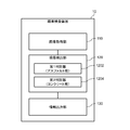
- FIG. 1 is a diagram illustrating a functional configuration of the road surface inspection device 10 according to the first embodiment.
- the road surface inspection device 10 according to the present embodiment includes an image acquisition unit 110, a damage detection unit 120, and an information output unit 130.
- the image acquisition unit 110 acquires an image showing the road surface to be inspected. As illustrated in FIG. 1, the image of the road surface is generated by the image pickup device 22 provided in the vehicle 20. Specifically, while the vehicle 20 is traveling on the road in the inspection target section, the image pickup device 22 performs a photographing operation to generate a road surface image of the road in the inspection target section. The image acquisition unit 110 acquires at least one of a plurality of frame images constituting the road surface image as an image to be image-processed (analyzed). When the image pickup device 22 has a function of connecting to a network such as the Internet, the image acquisition unit 110 may acquire an image of the road surface from the image pickup device 22 via the network.
- a network such as the Internet
- the image acquisition unit 110 may acquire a road surface image from, for example, an image pickup device 22 connected by a communication cable or a portable storage medium such as a memory card.
- the damage detection unit 120 uses the image of the road surface acquired by the image acquisition unit 110 as a target area for image processing for detecting road damage based on the attributes of the road appearing in the image (hereinafter, “target area”). ”) Is set. Then, the damage detection unit 120 performs image processing for detecting the damage on the road with respect to the set target area.
- Road damage detected by image processing includes, for example, cracks, rutting, potholes, depressions, depressions, and steps on the road surface.
- the information output unit 130 When the damage detection unit 120 detects road damage, the information output unit 130 generates and outputs information that can identify the position where the damage is detected (hereinafter, also referred to as "position identification information").
- the information output unit 130 includes information (that is, the latitude and longitude of the road) indicating the shooting position (latitude and longitude) of the image included in the metadata of the image to be processed (for example, Exif (ExchangeableImageFileFormat)). Information indicating the latitude) can be used as position identification information.
- the image acquisition unit 110 acquires the position data together with the image
- the information output unit 130 can use the position data acquired together with the image as the position identification information.
- the position of the road shown in the image to be processed can be estimated from the frame number of the video data.
- the information output unit 130 may use the frame number of the image to be processed as the position identification information. In this case, the information output unit 130 generates and outputs position identification information including at least one of the latitude / longitude information of the road and the frame number in one video data.
- the damage detection unit 120 is configured to further recognize a specific object (eg, a kilometer post, a sign indicating an address or a road name, etc.) whose shooting position can be specified in image processing, and the information output unit 130 is configured.
- a specific object eg, a kilometer post, a sign indicating an address or a road name, etc.
- Information obtained from the recognition result of the specific object may be used as position identification information.
- Each functional component of the road surface inspection device 10 may be realized by hardware that realizes each functional component (eg, a hard-wired electronic circuit, etc.), or a combination of hardware and software (eg, example). It may be realized by a combination of an electronic circuit and a program that controls it).
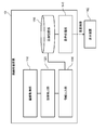
- FIG. 2 is a block diagram illustrating a hardware configuration of the road surface inspection device 10.
- the road surface inspection device 10 includes a bus 1010, a processor 1020, a memory 1030, a storage device 1040, an input / output interface 1050, and a network interface 1060.
- the bus 1010 is a data transmission path for the processor 1020, the memory 1030, the storage device 1040, the input / output interface 1050, and the network interface 1060 to transmit and receive data to and from each other.
- the method of connecting the processors 1020 and the like to each other is not limited to the bus connection.
- the processor 1020 is a processor realized by a CPU (Central Processing Unit), a GPU (Graphics Processing Unit), or the like.
- the memory 1030 is a main storage device realized by a RAM (Random Access Memory) or the like.
- the storage device 1040 is an auxiliary storage device realized by an HDD (Hard Disk Drive), an SSD (Solid State Drive), a memory card, a ROM (Read Only Memory), or the like.
- the storage device 1040 stores a program module that realizes each function of the road surface inspection device 10 (image acquisition unit 110, damage detection unit 120, information output unit 130, etc.).
- the processor 1020 reads each of these program modules into the memory 1030 and executes them, each function corresponding to each program module is realized.
- the input / output interface 1050 is an interface for connecting the road surface inspection device 10 and various input / output devices.
- An input device such as a keyboard or mouse, an output device (not shown) such as a display or a printer may be connected to the input / output interface 1050.
- an image pickup device 22 (or a portable storage medium provided in the image pickup device 22) may be connected to the input / output interface 1050.
- the road surface inspection device 10 can communicate with the image pickup device 22 (or a portable storage medium provided in the image pickup device 22) via the input / output interface 1050 to acquire the road surface image generated by the image pickup device 22. ..
- the network interface 1060 is an interface for connecting the road surface inspection device 10 to the network.
- This network is, for example, LAN (Local Area Network) or WAN (Wide Area Network).
- the method of connecting the network interface 1060 to the network may be a wireless connection or a wired connection.
- the road surface inspection device 10 can communicate with the image pickup device 22 and a video database (not shown) via the network interface 1060 to acquire the road surface video generated by the image pickup device 22.
- the hardware configuration of the road surface inspection device 10 is not limited to the configuration illustrated in FIG.
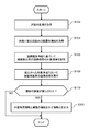
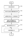
- FIG. 3 is a flowchart illustrating a flow of processing executed by the road surface inspection device 10 of the first embodiment.
- the image acquisition unit 110 acquires an image of the road to be processed (S102).
- the image acquisition unit 110 acquires the road surface image generated by the image pickup apparatus 22 via, for example, the input / output interface 1050 and the network interface 1060.
- the image acquisition unit 110 reads all or a part of the plurality of frame images constituting the road surface image as an image of the road to be processed.
- the image acquisition unit 110 may be configured to execute pre-processing on the image of the road in order to improve the efficiency of processing in the post-process.
- the image acquisition unit 110 may execute preprocessing such as front correction processing and deblurring processing on the road image.
- the damage detection unit 120 acquires information (road attribute information) indicating the attributes of the road appearing in the image to be processed acquired by the image acquisition unit 110 (S104).
- the attributes of a road are, for example, the position information of the road (for example, GPS (Global Positioning System) information), the laying environment of the road (for example, mountainous area or flat land), and the type of road surface (type of pavement material: for example. , Concrete, asphalt, gravel, bricks, cobblestones, etc.), the time elapsed since the road was laid, the traffic volume of vehicles at the location of the road, and at least one of the past damage history at the location of the road. Including. Below are some specific examples of how to get the attributes of a road. However, the method of acquiring road attributes is not limited to the examples shown below.
- the damage detection unit 120 can acquire information indicating a shooting position of the image (the position of the road reflected in the image) as road attribute information from, for example, Exif data of the image to be processed. Further, when the image acquired by the image acquisition unit 110 is associated with position information such as GPS information (information indicating the shooting position of the image), the damage detection unit 120 processes the position information. It can be acquired as road attribute information of the road shown in the image. In addition, a database (shown) that stores information indicating road attributes such as road laying environment, road surface type, road laying date and time, vehicle traffic volume, and past damage history in association with road position information. If the above is constructed, the damage detection unit 120 refers to the database based on the position information of the road shown in the image to be processed, and thereby at least one of the information indicating the above-mentioned attributes. Can be obtained.
- the damage detection unit 120 may be configured to determine the attributes of the road based on the image.
- the damage detection unit 120 may be configured to discriminate the attributes of the road (such as the laying environment and the type of road surface) appearing in the input image by using a discriminator constructed by rule base or machine learning. Good. For example, by preparing a plurality of learning data combining a road image and a label (correct answer label) indicating the environment of the road laying place and the type of road surface, and repeating machine learning using the plurality of learning data, It is possible to construct a discriminator capable of discriminating the road laying environment and the type of road surface of the road reflected in an unknown input image (road image).
- the damage detection unit 120 sets a target area for image processing for damage detection based on the acquired road attribute information (S106).
- FIG. 4 is a diagram illustrating setting rule information that defines a rule for setting a target area.
- the setting rule information exemplified in FIG. 4 defines the division of the road as the target area of the image processing for damage detection in association with the information of the section (road position).
- the setting rule information illustrated in FIG. 4 defines the division of the road as the target area of image processing for damage detection as "roadway” and "road shoulder” in section A and only "roadway” in section B, respectively.
- the setting rule information as shown in FIG. 4 is input in advance by, for example, a road manager or an inspection company that undertakes inspection work, and is stored in a storage area (memory 1030, storage device 1040, etc.) of the road surface inspection device 10. Will be done.
- the damage detection unit 120 sets the “road” and “road” based on the setting rule information exemplified in FIG. A road division called "road shoulder” is specified, and the pixel area corresponding to the "roadway” and “road shoulder” is set as a target area for image processing for damage detection.
- the damage detection unit 120 classifies the road as "road” based on the setting rule information exemplified in FIG.
- the pixel area corresponding to the specified "roadway” is set as the target area of image processing for damage detection.
- a setting rule may be provided in which the division of the roadway is subdivided into lane units.
- FIG. 17 is a diagram showing another example of setting rule information that defines a rule for setting a target area.
- the damage detection unit 120 sets the "traveling lane” and the "oncoming lane” based on the setting rule information exemplified in FIG. ”And“ shoulder ”to identify the road divisions. Then, the damage detection unit 120 sets the pixel areas corresponding to the “traveling lane”, the “oncoming lane”, and the “road shoulder” as the target areas for image processing for damage detection. Further, when the position information of the road acquired as the road attribute information indicates the position included in the section B, the damage detection unit 120 divides the road as "traveling lane” based on the setting rule information exemplified in FIG. To identify.
- the damage detection unit 120 sets the pixel area corresponding to the “traveling lane” as the target area for image processing for damage detection. Further, when the position information of the road acquired as the road attribute information indicates the position included in the section C, the damage detection unit 120 sets the "traveling lane” and the “passing lane” based on the setting rule information exemplified in FIG. Identify the road division called "lane”. Then, the damage detection unit 120 sets the pixel area corresponding to the “traveling lane” and the “passing lane” as the target area for image processing for damage detection.
- the damage detection unit 120 sets the "first lane” and "1st lane” based on the setting rule information exemplified in FIG. Identify the road categories of "second driving lane” and "passing lane”. Then, the damage detection unit 120 sets the pixel area corresponding to the “first traveling lane”, the “second traveling lane”, and the “passing lane” as the target area for image processing for damage detection.
- the damage detection unit 120 includes "oncoming lane", “traveling lane (first traveling lane / second traveling lane)", based on detection positions of marks such as the center line of the road, the boundary line of the lane, and the outside line of the road. It is possible to specify the pixel area corresponding to the classification such as "passing lane” and "road shoulder”.
- the damage detection unit 120 when the damage detection unit 120 acquires the road attribute information indicating the road laying environment, the damage detection unit 120 can set the target area according to the laying environment indicated by the road attribute information.
- the damage detection unit 120 acquires the road attribute information indicating that the road laying environment is such a section, for example, the area including the area outside the road outer line is image-processed for damage detection.
- the damage detection unit 120 acquires as road attribute information that the road laying environment is a section for which only the roadway is a damage detection target, for example, the area inside the roadway outer line is image-processed for damage detection. Set as the target area of.
- the damage detection unit 120 when the damage detection unit 120 acquires the road attribute information indicating the type of the road surface, the damage detection unit 120 is based on the type of the road surface indicated by the road attribute information and the judgment criteria set by the road manager or the inspection company. Therefore, the target area for image processing for damage detection can be set.
- a road manager or an inspection company may inspect only a predetermined type of road surface.
- road managers and inspection companies only inspect road surfaces paved with asphalt or concrete, not road surfaces paved with other materials such as gravel (gravel roads). Such a case is also conceivable.
- the damage detection unit 120 sets the target area when the type of the road surface indicated by the road attribute information is asphalt pavement or concrete pavement, and sets the target area when it is another type such as gravel (gravel road). Do not set as (not to be detected).
- the damage detection unit 120 when the damage detection unit 120 acquires the road attribute information indicating the traffic volume of the road, the damage detection unit 120 sets a target area for image processing for damage detection according to the traffic volume indicated by the road attribute information. Can be done. For example, the damage detection unit 120 sets the roadway and the shoulder as the target area in the section where the traffic volume is heavy (the traffic volume exceeds a predetermined threshold value), and the section where the traffic volume is low (the traffic volume exceeds a predetermined threshold value). Only the roadway can be set as the target area for image processing for damage detection.
- the damage detection unit 120 can determine a target area for image processing for damage detection based on the past damage history.
- the damage detection unit 120 is for damage detection so as to include both the area inside the roadway outer line (roadway area) and the area outside the roadway outside line (for example, the area of the road shoulder or the ground on the side of the road). Set the target area for image processing.
- the damage detection unit 120 can specify an area corresponding to a road division such as "roadway” or "shoulder” from the image, for example, as follows. First, the damage detection unit 120 detects predetermined marks (lane markings, road markings, curbs, guardrails, etc.) for identifying the road area from the image to be processed. In this case, the damage detection unit 120 can use, for example, an algorithm for detecting a mark on the road, which is known in the field of automatic driving technology and the like. Then, the damage detection unit 120 determines the area corresponding to the road based on the detection position of the predetermined mark. In some cases, a predetermined mark such as a road outside line cannot be detected in the image to be processed.
- predetermined marks latitude, road markings, curbs, guardrails, etc.
- the damage detection unit 120 determines the road area and the ground area outside the road based on, for example, the color features that can be extracted from the image, or the road area and the ground outside the road by machine learning. It may be configured to determine the area of the road using a discriminator constructed so that the boundary with the area can be discriminated. After the road area is determined, the damage detection unit 120 divides the road area into a plurality of areas (roadway area, shoulder area, sidewalk area, etc.) in the width direction. Then, the damage detection unit 120 uses the result of dividing the road shown in the image into a plurality of regions (for example, a roadway, a shoulder, a sidewalk, etc.) in the width direction of the road, and sets a target region for image processing for damage detection.
- a discriminator constructed so that the boundary with the area can be discriminated.
- the damage detection unit 120 executes image processing for damage detection on the set target area (S108). As a result of this image processing, it is determined whether or not the road shown in the image to be processed has damage.
- the information output unit 130 outputs position identification information capable of identifying the position of the damaged road (S112).
- the information output unit 130 can acquire, for example, information indicating a shooting position of an image included in Exif data, a frame number of an image to be processed in a road surface image, and the like as position identification information.
- the information output unit 130 lists the position information generated based on the image processing result of each image included in the road surface image in a predetermined format (for example, CSV (Comma Separated Values) format). Output to a storage area such as memory 1030 or storage device 1040. Further, the information output unit 130 may be configured to display and output a list of position identification information on a display (not shown).
- a target area for image processing for damage detection is set based on the attributes of the road appearing in the image to be processed.
- image processing for damage detection is executed for the set target area.
- the position identification information capable of identifying the position where the damage to the road is detected by the image processing is output. A person engaged in road inspection work can easily grasp the position of a damaged road by referring to this position identification information.
- the road surface inspection device 10 of the present embodiment has the same configuration as that of the first embodiment except for the points described below.
- the damage detection unit 120 is configured to switch the discriminator (processing logic for detecting road damage) used in the image processing for damage detection based on the attributes of the road appearing in the image. Will be done.
- FIG. 5 is a diagram illustrating the functional configuration of the road surface inspection device 10 of the second embodiment.
- the road surface inspection device 10 has a discriminator (processing logic) for each type of road surface, and the damage detection unit 120 performs image processing according to the type of road surface of the road shown in the image to be processed. It is configured to switch the discriminator used.
- the road surface inspection device 10 is a first discriminator 1202 specially constructed for damage to a road surface paved with asphalt, and a first discriminator 1202 specially constructed for damage to a road surface paved with concrete. It has two discriminators 1204.
- a discriminator specialized for other types of road surface damage such as cobblestones and gravel may be further prepared.
- a discriminator corresponding to other attributes such as a road laying environment and traffic volume may be further prepared.
- FIG. 6 is a flowchart illustrating a flow of processing executed by the road surface inspection device 10 of the second embodiment.
- the flowchart of the present embodiment is different from the flowchart of FIG. 3 in that the process of S202 is further included.
- the damage detection unit 120 selects a discriminator (processing logic) to be used in image processing based on the road attribute information acquired in the processing of S104 (S202). For example, when the road attribute information indicating that the road surface type is asphalt is acquired, the damage detection unit 120 selects the first discriminator 1202 as the discriminator used in the image processing. Then, in the process of S108, the damage detection unit 120 executes image processing using the discriminator selected in the process of S202 on the target area set in the process of S106.
- a discriminator processing logic
- a plurality of discriminators are prepared according to the attributes of the road, and the discriminators corresponding to the attributes of the road appearing in the image to be processed are used. Image processing is executed.
- image processing for damage detection using a discriminator (processing logic) suitable for the attributes of the road, the effect of improving the accuracy of detecting damage on the road can be obtained.
- the type of damage present on the road is the information needed to determine the repair work to be done later.
- the damage detection unit 120 is configured to further identify the type of damage detected in the image processing.
- the information output unit 130 is configured to further output information indicating the type of road damage detected in the image processing in association with the position identification information.
- FIG. 7 is a diagram illustrating the functional configuration of the road surface inspection device 10 according to the third embodiment.
- the damage detection unit 120 includes a discriminator 1206 constructed to output information indicating the type of damage detected in the image processing.
- the discriminator 1206 uses, for example, learning data that combines a learning image with a correct label indicating the type of damage present in the image (cracks, rutting, potholes, depressions, depressions, steps, etc.). By repeating machine learning, the type of damage can be identified.
- FIG. 8 is a flowchart illustrating a flow of processing executed by the road surface inspection device 10 of the third embodiment.
- the process of S302 in the flowchart of the present embodiment is different from the flowchart of FIG.
- the information output unit 130 when road damage is detected in the image processing of S108, the information output unit 130 outputs information including information indicating the type of the detected damage and position identification information (S302).
- the information output unit 130 outputs CSV format data including, for example, position identification information and information indicating the type of damage (for example, code information assigned to each type of damage) in one record.
- the position identification information that can identify the position of the damaged road and the information indicating the type of damage detected at that position are output.
- a person involved in road maintenance and inspection work can easily understand what kind of repair measures are required at which position by checking the location identification information and the information indicating the type of damage to the road. be able to.
- the information output unit 130 calculates a score (degree of damage) for each type of damage identified in the image processing, and further outputs information indicating the score calculated for each type of damage. It may be configured in. For example, the information output unit 130 adds up the area (number of pixels) of the image area in which damage is detected for each type of damage, and determines the degree of damage as the ratio of the total area to the area of the target area for image processing. It may be configured to be calculated and output as information to be shown. Persons involved in road maintenance and inspection work will be able to appropriately prioritize repair work based on information indicating the type of damage and the degree of damage.
- the urgency of repair may differ depending on the type and location of damage.
- a pothole is more likely to have an adverse effect on the passage of vehicles and people than a crack, and can be said to be an urgent damage for repair.
- the former position is more likely to adversely affect the passing vehicle or person, and repair is urgent. It can be said that the damage is highly sexual. Therefore, the information output unit 130 may be configured to calculate the degree of damage by weighting according to the type and position of the detected damage.
- the information output unit 130 is configured to calculate the degree of damage by using a weighting coefficient defined in advance for each type of damage and a weighting coefficient determined according to the damage detection position.
- the "degree of damage" output from the information output unit 130 becomes information that more accurately indicates the urgency of repair. That is, the "degree of damage” output from the information output unit 130 becomes more useful information for the person who performs the maintenance and inspection work of the road. For example, a person who performs road maintenance and inspection work can make an efficient plan, such as prioritizing more effective repair work based on the "degree of damage" output from the information output unit 130. It will be possible.
- the present embodiment has the same configuration as any one of the first embodiment, the second embodiment, and the third embodiment except for the points described below.
- FIG. 9 is a diagram illustrating the functional configuration of the road surface inspection device 10 according to the fourth embodiment.
- the road surface inspection device 10 of the present embodiment further includes a display processing unit 140 and an image storage unit 150.
- the display processing unit 140 displays the superimposed image on the display device 142 connected to the road surface inspection device 10.
- the superimposed image is an image in which information indicating the position of damage on the road detected by image processing is superimposed on the image of the road, and is generated by, for example, the information output unit 130.
- the information output unit 130 identifies an area where damage is located in an image of a road to be processed based on the result of image processing executed by the damage detection unit 120, and superimposes the position of the area so that it can be distinguished. Generate data. Then, the information output unit 130 generates a superposed image by superimposing the superposed data on the image of the road.
- the information output unit 130 stores the generated superimposed image in the image storage unit 150 (for example, a memory 1030, a storage device 1040, etc.) in association with the position identification information. For example, when the display processing unit 140 receives an input for designating the position identification information corresponding to the image to be displayed, the display processing unit 140 reads the superimposed image stored in association with the designated position correspondence information from the image storage unit 150 and displays it. Displayed on the device 142.
- the image storage unit 150 for example, a memory 1030, a storage device 1040, etc.
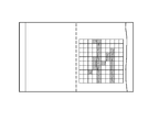
- ⁇ Display example of superimposed image> 10 to 14 are views showing an example of a superimposed image displayed by the display processing unit 140 of the fourth embodiment. It should be noted that these figures are examples, and do not limit the content of the invention of the present embodiment.
- the superimposed image illustrated in FIG. 10 includes a display element on the square indicating the target area and a display element highlighting the square corresponding to the position where the damage is detected. With such a superposed image, it is possible to grasp at a glance which position is damaged.
- the display processing unit 140 may perform front correction processing when displaying the superimposed image.
- a superposed image of the road as seen from above is displayed on the display device 142 as shown in FIG. According to the image as illustrated in FIG. 11, the magnitude of damage can be accurately grasped.
- the front correction process may be performed by the information output unit 130 when the superimposed image is generated.
- the superimposed image may include information indicating the degree of damage (“damage rate” in the example of this figure).
- the information output unit 130 calculates the degree of damage based on the size of the target area for image processing (the number of squares and the number of pixels) and the size of the damaged area, and superimposes the calculation result. Is stored in the image storage unit 150 in association with the above. Then, when displaying the superimposed image, the display processing unit 140 reads out the information indicating the degree of damage together with the superimposed image and displays it at a predetermined display position.
- the information output unit 130 may be configured to calculate the degree of damage for each road category. In this case, as shown in FIG. 13, for example, the display processing unit 140 displays information indicating the degree of damage at a position corresponding to each road division (“roadway”, “shoulder”, etc.).
- the score for each type of damage is as shown in FIG. A superposed image containing information indicating the above may be generated. With such a superimposed image, it is possible to easily grasp what kind of damage is at which position on the road. For example, according to the superimposed image illustrated in FIG. 14, in the area of the roadway, there are cracks showing 19% of the area, potholes occupying 6% of the area, and the area of the shoulder. It can be easily grasped that there is a pothole that occupies 10% of the area.
- a person who performs road maintenance and inspection work can easily confirm the damaged state of the damaged road.
- the road surface inspection device 10 of the present embodiment is different from each of the above-described embodiments in the points described below.
- FIG. 15 is a diagram illustrating the functional configuration of the road surface inspection device 10 according to the fifth embodiment.
- the damage detection unit 120 of the present embodiment has a plurality of determination devices (image processing processing logic for detecting damage on the road surface).
- the damage detection unit 120 of the present embodiment selects a determination device corresponding to the attribute from a plurality of determination devices based on the attribute of the road shown in the image. Then, the damage detection unit 120 of the present embodiment executes image processing for damage detection using the selected determination device.
- the damage detection unit 120 of the present embodiment does not have the function of setting the target area for image processing based on the road attribute information as described in each of the above-described embodiments.
- the hardware configuration is the same as in FIG.
- the storage device 1040 stores a program module for realizing the above-mentioned function of the damage detection unit 120 instead of the program module for realizing the function of the damage detection unit 120. Further, when the processor 1020 reads this program into the memory 1030 and executes it, the function of the damage detection unit 120 described above is realized.
- FIG. 16 is a flowchart illustrating a flow of processing executed by the road surface inspection device 10 of the fifth embodiment.
- the image acquisition unit 110 acquires an image of the road to be processed (S502).
- the damage detection unit 120 acquires information (road attribute information) indicating the attributes of the road appearing in the image to be processed acquired by the image acquisition unit 110 (S504).
- the processing of S502 and S504 is the same as the processing of S102 and S104 of FIG. 3, respectively.
- the damage detection unit 120 selects a discriminator corresponding to the road attribute information of the road shown in the image to be processed from a plurality of discriminators prepared for each attribute (S506). For example, when the road attribute information indicating that the road surface type is "asphalt" is acquired, the damage detection unit 120 selects a discriminator specially constructed for "asphalt". Then, the damage detection unit 120 executes image processing for damage detection using the selected discriminator (S508). As a result of this image processing, it is determined whether or not the road shown in the image to be processed has damage.
- the information output unit 130 When damage is detected by image processing (S510: YES), the information output unit 130 generates and outputs position identification information capable of identifying the position of the damaged road (S512).
- the processing of S510 and S512 is the same as the processing of S110 and S112 of FIG. 3, respectively.
- the image processing for damage detection is executed by using the processing logic corresponding to the road attribute information of the road reflected in the image to be processed. That is, the image processing for damage detection is executed by using the processing logic specialized for the attribute of the road shown in the image. By doing so, it is possible to improve the accuracy of detecting damage caused by image processing.
- Image acquisition means to acquire an image of the road
- a damage detection means that sets a target area in the image of the image processing for detecting damage to the road based on the attributes of the road reflected in the image, and performs the image processing on the set target area.
- An information output means for outputting position identification information capable of identifying the position of the road where damage was detected by the image processing, and A road surface inspection device equipped with.
- the damage detecting means detects a region corresponding to a road from the image and sets the target region in the detected region. 1. 1. The road surface inspection device described in. 3. 3.
- the damage detecting means is The road shown in the image is divided into a plurality of areas in the width direction of the road.
- the target area is set using the result of dividing the road into a plurality of areas.
- the road attributes include at least one of location information, laying environment, road surface type, elapsed time since the road was laid, vehicle traffic, and past damage history. 1. 1. From 3.
- the attribute of the road is the position information of the road.
- the damage detecting means sets the target area based on the area setting rule associated with the position information of the road in advance. 4.
- the damage detecting means determines the attributes of the road based on the image. 1. 1. From 5.
- the damage detecting means switches the processing logic used in the image processing based on the attributes of the road. 1. 1. From 6. The road surface inspection device according to any one of the above. 8. The attribute of the road is the type of road surface of the road. The damage detecting means determines the processing logic used in the image processing based on the type of the road surface. 7. The road surface inspection device described in. 9. The damage detecting means further identifies the type of road damage in the image processing and The information output means further outputs information indicating the type of damage to the road detected by the image processing. 1. 1. From 8. The road surface inspection device according to any one of the above. 10. The information output means calculates the degree of damage for each type of damage on the identified road, and further outputs information indicating the degree of damage calculated for each type of damage. 9.
- the position-specific information includes at least one of the latitude / longitude information of the road and the frame number of the image. 1. 1.
- To 10. The road surface inspection device according to any one of the above. 12.
- a display processing means for displaying on a display device a superimposed image in which information indicating the position of road damage detected by the image processing is superimposed on the image is further provided. 1. 1. From 11.
- the road surface inspection device according to any one of the above. 13 The computer Get an image of the road and The target area in the image of the image processing for detecting the damage of the road is set based on the attribute of the road reflected in the image. The image processing is performed on the set target area, and the image processing is performed.
- Road surface inspection method including that. 14.
- the computer A region corresponding to a road is detected from the image, and the target region is set in the detected region. Including 13.
- the computer The road shown in the image is divided into a plurality of areas in the width direction of the road. The target area is set using the result of dividing the road into a plurality of areas. Including 14.
- the road attributes include at least one of location information, laying environment, road surface type, elapsed time since the road was laid, vehicle traffic, and past damage history. 13. To 15. The road surface inspection method according to any one of the above. 17.
- the attribute of the road is the position information of the road.
- the computer The target area is set based on the area setting rule associated with the position information of the road in advance. Including 16. Road surface inspection method described in. 18.
- the computer Judging the attributes of the road based on the image, Including 13. From 17.
- the computer The processing logic used in the image processing is switched based on the attributes of the road. Including 13. To 18.
- the attribute of the road is the type of road surface of the road.
- the computer The processing logic used in the image processing is determined based on the type of the road surface. Including that 19. Road surface inspection method described in. 21.
- the computer The type of road damage was further identified in the image processing.
- Image acquisition means to acquire an image of the road
- a damage detection means that selects an image processing processing logic for detecting damage to the road surface based on the attributes of the road shown in the image, and performs image processing on the image using the selected processing logic.
- An information output means for outputting position identification information capable of identifying the position of the road where damage was detected by the image processing, and A road surface inspection device equipped with.
Landscapes
- Engineering & Computer Science (AREA)
- General Physics & Mathematics (AREA)
- Theoretical Computer Science (AREA)
- Physics & Mathematics (AREA)
- Multimedia (AREA)
- Computer Vision & Pattern Recognition (AREA)
- Quality & Reliability (AREA)
- Architecture (AREA)
- Civil Engineering (AREA)
- Structural Engineering (AREA)
- Road Repair (AREA)
- Traffic Control Systems (AREA)
- Image Analysis (AREA)
Priority Applications (4)
| Application Number | Priority Date | Filing Date | Title |
|---|---|---|---|
| JP2021527304A JP7276446B2 (ja) | 2019-06-28 | 2019-06-28 | 路面検査装置、路面検査方法、およびプログラム |
| PCT/JP2019/025949 WO2020261567A1 (ja) | 2019-06-28 | 2019-06-28 | 路面検査装置、路面検査方法、およびプログラム |
| US17/620,564 US20220262111A1 (en) | 2019-06-28 | 2019-06-28 | Road surface inspection apparatus, road surface inspection method, and program |
| JP2023016665A JP7517489B2 (ja) | 2019-06-28 | 2023-02-07 | 路面検査装置、路面検査方法、およびプログラム |
Applications Claiming Priority (1)
| Application Number | Priority Date | Filing Date | Title |
|---|---|---|---|
| PCT/JP2019/025949 WO2020261567A1 (ja) | 2019-06-28 | 2019-06-28 | 路面検査装置、路面検査方法、およびプログラム |
Publications (1)
| Publication Number | Publication Date |
|---|---|
| WO2020261567A1 true WO2020261567A1 (ja) | 2020-12-30 |
Family
ID=74061561
Family Applications (1)
| Application Number | Title | Priority Date | Filing Date |
|---|---|---|---|
| PCT/JP2019/025949 Ceased WO2020261567A1 (ja) | 2019-06-28 | 2019-06-28 | 路面検査装置、路面検査方法、およびプログラム |
Country Status (3)
| Country | Link |
|---|---|
| US (1) | US20220262111A1 (https=) |
| JP (2) | JP7276446B2 (https=) |
| WO (1) | WO2020261567A1 (https=) |
Cited By (5)
| Publication number | Priority date | Publication date | Assignee | Title |
|---|---|---|---|---|
| CN112800911A (zh) * | 2021-01-20 | 2021-05-14 | 同济大学 | 一种路面损伤快速检测及自然数据集构建方法 |
| CN114419461A (zh) * | 2022-01-19 | 2022-04-29 | 周琦 | 利用卫星通信的状态解析平台及方法 |
| JP7067852B1 (ja) | 2022-02-01 | 2022-05-16 | 株式会社ファンクリエイト | 路面損傷位置の算定方法 |
| CN116029959A (zh) * | 2021-10-26 | 2023-04-28 | 成都圭目机器人有限公司 | 一种道路病害的定位方法、装置及计算机可读存储介质 |
| JP2024128798A (ja) * | 2023-03-10 | 2024-09-24 | 三菱自動車工業株式会社 | 路上物体検出システム及び路上物体検出方法 |
Families Citing this family (10)
| Publication number | Priority date | Publication date | Assignee | Title |
|---|---|---|---|---|
| CN112598672A (zh) * | 2020-11-02 | 2021-04-02 | 坝道工程医院(平舆) | 一种基于深度学习的路面病害图像分割方法和系统 |
| CN113963196B (zh) * | 2021-09-28 | 2024-11-29 | 武汉理工大学 | 基于机器学习的实时路面切换快速识别方法及电子设备 |
| US12602767B1 (en) * | 2022-11-15 | 2026-04-14 | University Of South Florida | System of and method for analyzing thoroughfare conditions via oil spot analysis |
| CN115810267A (zh) * | 2022-11-17 | 2023-03-17 | 河北冀通慧达科技有限公司 | 道路安全隐患排查方法、装置及终端设备 |
| US20240218615A1 (en) * | 2023-01-03 | 2024-07-04 | Crafco, Inc. | System and method for robotic sealing of defects in paved surfaces |
| JPWO2024204596A1 (https=) | 2023-03-29 | 2024-10-03 | ||
| KR102927040B1 (ko) * | 2023-06-20 | 2026-02-12 | 주식회사 베이리스 | 포트홀 검출 시스템 및 그 검출 방법 |
| US12444004B2 (en) * | 2024-02-02 | 2025-10-14 | AIDASH Inc. | Systems and methods for road infrastructure management |
| CN118230201B (zh) * | 2024-04-15 | 2024-10-18 | 山东省交通工程监理咨询有限公司 | 一种基于无人机的高速公路智能图像处理方法 |
| CN118565404B (zh) * | 2024-07-09 | 2024-09-24 | 杭州海康威视数字技术股份有限公司 | 道路病害位置确定方法、装置、电子设备及可读存储介质 |
Citations (3)
| Publication number | Priority date | Publication date | Assignee | Title |
|---|---|---|---|---|
| JP2009179997A (ja) * | 2008-01-30 | 2009-08-13 | Fuji Electric Systems Co Ltd | 道路情報管理装置 |
| JP2018017101A (ja) * | 2016-07-29 | 2018-02-01 | エヌ・ティ・ティ・コムウェア株式会社 | 情報処理装置、情報処理方法、及びプログラム |
| JP2019100136A (ja) * | 2017-12-06 | 2019-06-24 | 株式会社東芝 | 道路維持管理システム、道路維持管理方法及びコンピュータプログラム |
Family Cites Families (2)
| Publication number | Priority date | Publication date | Assignee | Title |
|---|---|---|---|---|
| CN107615050B (zh) * | 2015-05-26 | 2021-04-23 | 三菱电机株式会社 | 检测装置及检测方法 |
| JP6779698B2 (ja) * | 2016-08-03 | 2020-11-04 | 株式会社東芝 | 舗装ひび割れ解析装置、舗装ひび割れ解析方法及び舗装ひび割れ解析プログラム |
-
2019
- 2019-06-28 US US17/620,564 patent/US20220262111A1/en not_active Abandoned
- 2019-06-28 WO PCT/JP2019/025949 patent/WO2020261567A1/ja not_active Ceased
- 2019-06-28 JP JP2021527304A patent/JP7276446B2/ja active Active
-
2023
- 2023-02-07 JP JP2023016665A patent/JP7517489B2/ja active Active
Patent Citations (3)
| Publication number | Priority date | Publication date | Assignee | Title |
|---|---|---|---|---|
| JP2009179997A (ja) * | 2008-01-30 | 2009-08-13 | Fuji Electric Systems Co Ltd | 道路情報管理装置 |
| JP2018017101A (ja) * | 2016-07-29 | 2018-02-01 | エヌ・ティ・ティ・コムウェア株式会社 | 情報処理装置、情報処理方法、及びプログラム |
| JP2019100136A (ja) * | 2017-12-06 | 2019-06-24 | 株式会社東芝 | 道路維持管理システム、道路維持管理方法及びコンピュータプログラム |
Cited By (9)
| Publication number | Priority date | Publication date | Assignee | Title |
|---|---|---|---|---|
| CN112800911A (zh) * | 2021-01-20 | 2021-05-14 | 同济大学 | 一种路面损伤快速检测及自然数据集构建方法 |
| CN112800911B (zh) * | 2021-01-20 | 2022-12-16 | 同济大学 | 一种路面损伤快速检测及自然数据集构建方法 |
| CN116029959A (zh) * | 2021-10-26 | 2023-04-28 | 成都圭目机器人有限公司 | 一种道路病害的定位方法、装置及计算机可读存储介质 |
| CN116029959B (zh) * | 2021-10-26 | 2026-03-17 | 成都圭目机器人有限公司 | 一种道路病害的定位方法、装置及计算机可读存储介质 |
| CN114419461A (zh) * | 2022-01-19 | 2022-04-29 | 周琦 | 利用卫星通信的状态解析平台及方法 |
| JP7067852B1 (ja) | 2022-02-01 | 2022-05-16 | 株式会社ファンクリエイト | 路面損傷位置の算定方法 |
| JP2023112536A (ja) * | 2022-02-01 | 2023-08-14 | 株式会社ファンクリエイト | 路面損傷位置の算定方法 |
| JP2024128798A (ja) * | 2023-03-10 | 2024-09-24 | 三菱自動車工業株式会社 | 路上物体検出システム及び路上物体検出方法 |
| JP7845234B2 (ja) | 2023-03-10 | 2026-04-14 | 三菱自動車工業株式会社 | 路上物体検出システム及び路上物体検出方法 |
Also Published As
| Publication number | Publication date |
|---|---|
| JP7276446B2 (ja) | 2023-05-18 |
| JP2023054011A (ja) | 2023-04-13 |
| JPWO2020261567A1 (https=) | 2020-12-30 |
| JP7517489B2 (ja) | 2024-07-17 |
| US20220262111A1 (en) | 2022-08-18 |
Similar Documents
| Publication | Publication Date | Title |
|---|---|---|
| JP7517489B2 (ja) | 路面検査装置、路面検査方法、およびプログラム | |
| Hadjidemetriou et al. | Automated pavement patch detection and quantification using support vector machines | |
| US12475375B2 (en) | Systems and methods for assessing infrastructure | |
| CN106203398B (zh) | 一种检测车道边界的方法、装置和设备 | |
| KR20190094005A (ko) | 도로 노면 손상 탐지를 위한 영상 처리 및 딥러닝 이미지 분류 장치 및 방법 | |
| CN109785637B (zh) | 车辆违规的分析评价方法及装置 | |
| JP2020035104A (ja) | 道路維持管理システム、道路維持管理方法及びコンピュータプログラム | |
| CN117474870B (zh) | 一种基于大数据筛选的公路路面裂缝识别决策方法及系统 | |
| JP2019196680A (ja) | 舗装情報収集点検システム、舗装情報収集点検方法、及びプログラム | |
| EP4273501A1 (en) | Method, apparatus, and computer program product for map data generation from probe data imagery | |
| KR102026686B1 (ko) | 커넥티드 차량을 이용한 도로 파손 정보 제공 장치 및 도로 파손 판정 모델 생성 서버 | |
| US20200334485A1 (en) | System and method for analyzing an image of a vehicle | |
| JP6678267B1 (ja) | 道路不具合検出装置、道路不具合検出方法及び道路不具合検出プログラム | |
| JP2026001198A (ja) | 画像生成システム、画像生成方法、及び、プログラム | |
| CN106780270B (zh) | 公路路面管理装置及方法 | |
| CN108665556B (zh) | 一种基于混合现实的路政指示显示方法及存储介质 | |
| WO2020261568A1 (ja) | 路面検査装置、路面検査方法、およびプログラム | |
| Steele et al. | Traffic sign retroreflectivity condition assessment and deterioration analysis using Lidar technology | |
| KR20220138894A (ko) | 노면표시 정보의 예측 및 인식방법 및 도로 유지관리 방법 | |
| CN116206326B (zh) | 缺失检测模型的训练方法、导流区的缺失检测方法及装置 | |
| Santos Maia et al. | Safety-oriented urban pavement design and evaluation: integrating microscopic simulation and tyre-pavement friction | |
| KR20220080975A (ko) | 주행환경 정적객체인지 ai 데이터 처리 방법 및 이를 위한 장치 | |
| JP7823741B2 (ja) | ポットホール予測システム、ポットホール予測方法及びプログラム | |
| WO2016114219A1 (ja) | 道路工事計画プログラム、道路工事計画方法および情報処理装置 | |
| Yi et al. | The color specification of surrogate roadside objects for the performance evaluation of roadway departure mitigation systems |
Legal Events
| Date | Code | Title | Description |
|---|---|---|---|
| 121 | Ep: the epo has been informed by wipo that ep was designated in this application |
Ref document number: 19935466 Country of ref document: EP Kind code of ref document: A1 |
|
| ENP | Entry into the national phase |
Ref document number: 2021527304 Country of ref document: JP Kind code of ref document: A |
|
| NENP | Non-entry into the national phase |
Ref country code: DE |
|
| 122 | Ep: pct application non-entry in european phase |
Ref document number: 19935466 Country of ref document: EP Kind code of ref document: A1 |