WO2020261567A1 - 路面検査装置、路面検査方法、およびプログラム - Google Patents
路面検査装置、路面検査方法、およびプログラム Download PDFInfo
- Publication number
- WO2020261567A1 WO2020261567A1 PCT/JP2019/025949 JP2019025949W WO2020261567A1 WO 2020261567 A1 WO2020261567 A1 WO 2020261567A1 JP 2019025949 W JP2019025949 W JP 2019025949W WO 2020261567 A1 WO2020261567 A1 WO 2020261567A1
- Authority
- WO
- WIPO (PCT)
- Prior art keywords
- road
- image
- damage
- road surface
- surface inspection
- Prior art date
Links
Images


Classifications
-
- G—PHYSICS
- G06—COMPUTING; CALCULATING OR COUNTING
- G06V—IMAGE OR VIDEO RECOGNITION OR UNDERSTANDING
- G06V20/00—Scenes; Scene-specific elements
- G06V20/10—Terrestrial scenes
- G06V20/182—Network patterns, e.g. roads or rivers
-
- G—PHYSICS
- G06—COMPUTING; CALCULATING OR COUNTING
- G06T—IMAGE DATA PROCESSING OR GENERATION, IN GENERAL
- G06T7/00—Image analysis
- G06T7/0002—Inspection of images, e.g. flaw detection
- G06T7/0004—Industrial image inspection
-
- E—FIXED CONSTRUCTIONS
- E01—CONSTRUCTION OF ROADS, RAILWAYS, OR BRIDGES
- E01C—CONSTRUCTION OF, OR SURFACES FOR, ROADS, SPORTS GROUNDS, OR THE LIKE; MACHINES OR AUXILIARY TOOLS FOR CONSTRUCTION OR REPAIR
- E01C23/00—Auxiliary devices or arrangements for constructing, repairing, reconditioning, or taking-up road or like surfaces
- E01C23/01—Devices or auxiliary means for setting-out or checking the configuration of new surfacing, e.g. templates, screed or reference line supports; Applications of apparatus for measuring, indicating, or recording the surface configuration of existing surfacing, e.g. profilographs
-
- G—PHYSICS
- G06—COMPUTING; CALCULATING OR COUNTING
- G06V—IMAGE OR VIDEO RECOGNITION OR UNDERSTANDING
- G06V10/00—Arrangements for image or video recognition or understanding
- G06V10/20—Image preprocessing
- G06V10/25—Determination of region of interest [ROI] or a volume of interest [VOI]
-
- G—PHYSICS
- G06—COMPUTING; CALCULATING OR COUNTING
- G06V—IMAGE OR VIDEO RECOGNITION OR UNDERSTANDING
- G06V10/00—Arrangements for image or video recognition or understanding
- G06V10/20—Image preprocessing
- G06V10/26—Segmentation of patterns in the image field; Cutting or merging of image elements to establish the pattern region, e.g. clustering-based techniques; Detection of occlusion
-
- G—PHYSICS
- G06—COMPUTING; CALCULATING OR COUNTING
- G06V—IMAGE OR VIDEO RECOGNITION OR UNDERSTANDING
- G06V10/00—Arrangements for image or video recognition or understanding
- G06V10/40—Extraction of image or video features
- G06V10/50—Extraction of image or video features by performing operations within image blocks; by using histograms, e.g. histogram of oriented gradients [HoG]; by summing image-intensity values; Projection analysis
-
- G—PHYSICS
- G06—COMPUTING; CALCULATING OR COUNTING
- G06V—IMAGE OR VIDEO RECOGNITION OR UNDERSTANDING
- G06V20/00—Scenes; Scene-specific elements
- G06V20/50—Context or environment of the image
- G06V20/56—Context or environment of the image exterior to a vehicle by using sensors mounted on the vehicle
- G06V20/588—Recognition of the road, e.g. of lane markings; Recognition of the vehicle driving pattern in relation to the road
-
- G—PHYSICS
- G06—COMPUTING; CALCULATING OR COUNTING
- G06T—IMAGE DATA PROCESSING OR GENERATION, IN GENERAL
- G06T2207/00—Indexing scheme for image analysis or image enhancement
- G06T2207/30—Subject of image; Context of image processing
- G06T2207/30108—Industrial image inspection
- G06T2207/30132—Masonry; Concrete
-
- G—PHYSICS
- G06—COMPUTING; CALCULATING OR COUNTING
- G06T—IMAGE DATA PROCESSING OR GENERATION, IN GENERAL
- G06T2207/00—Indexing scheme for image analysis or image enhancement
- G06T2207/30—Subject of image; Context of image processing
- G06T2207/30181—Earth observation
- G06T2207/30184—Infrastructure
-
- G—PHYSICS
- G06—COMPUTING; CALCULATING OR COUNTING
- G06T—IMAGE DATA PROCESSING OR GENERATION, IN GENERAL
- G06T2207/00—Indexing scheme for image analysis or image enhancement
- G06T2207/30—Subject of image; Context of image processing
- G06T2207/30236—Traffic on road, railway or crossing
Definitions
- the present invention relates to a technique for supporting the management work of the laid road surface.
- Patent Document 1 An example of a technique for efficiently inspecting a road is disclosed in Patent Document 1 below.
- Patent Document 1 below discloses an example of a technique for detecting damage (cracks, ruts, etc.) on the road surface of a road using an image of the road.
- the load on the computer due to image processing is large.
- the computer processes a large amount of the image of the road.
- the processing time on the computer becomes long, and the efficiency of business may decrease.
- a technology for speeding up processing on a computer is desired.
- the present invention has been made in view of the above problems.
- One of an object of the present invention is to provide a technique for improving the processing speed of an image by a computer when inspecting a road using an image of the road.
- the road surface inspection device of the present invention Image acquisition means to acquire an image of the road, A damage detection means that sets a target area in the image of the image processing for detecting damage to the road based on the attributes of the road reflected in the image, and performs the image processing on the set target area.
- An information output means for outputting position identification information capable of identifying the position of the road where damage was detected by the image processing, and To be equipped.
- the road surface inspection method of the present invention The computer Get an image of the road and The target area in the image of the image processing for detecting the damage of the road is set based on the attribute of the road reflected in the image. The image processing is performed on the set target area, and the image processing is performed. Outputs location identification information that can identify the position of the road where damage was detected by the image processing. Including that.
- the program of the present invention causes a computer to execute the above-mentioned road surface inspection method.
- each block diagram represents a configuration of a functional unit, not a configuration of a hardware unit.
- the direction of the arrow in the figure is for making the flow of information easy to understand, and does not limit the direction of communication (one-way communication / two-way communication) unless otherwise specified.
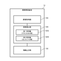
- FIG. 1 is a diagram illustrating a functional configuration of the road surface inspection device 10 according to the first embodiment.
- the road surface inspection device 10 according to the present embodiment includes an image acquisition unit 110, a damage detection unit 120, and an information output unit 130.
- the image acquisition unit 110 acquires an image showing the road surface to be inspected. As illustrated in FIG. 1, the image of the road surface is generated by the image pickup device 22 provided in the vehicle 20. Specifically, while the vehicle 20 is traveling on the road in the inspection target section, the image pickup device 22 performs a photographing operation to generate a road surface image of the road in the inspection target section. The image acquisition unit 110 acquires at least one of a plurality of frame images constituting the road surface image as an image to be image-processed (analyzed). When the image pickup device 22 has a function of connecting to a network such as the Internet, the image acquisition unit 110 may acquire an image of the road surface from the image pickup device 22 via the network.
- a network such as the Internet
- the image acquisition unit 110 may acquire a road surface image from, for example, an image pickup device 22 connected by a communication cable or a portable storage medium such as a memory card.
- the damage detection unit 120 uses the image of the road surface acquired by the image acquisition unit 110 as a target area for image processing for detecting road damage based on the attributes of the road appearing in the image (hereinafter, “target area”). ”) Is set. Then, the damage detection unit 120 performs image processing for detecting the damage on the road with respect to the set target area.
- Road damage detected by image processing includes, for example, cracks, rutting, potholes, depressions, depressions, and steps on the road surface.
- the information output unit 130 When the damage detection unit 120 detects road damage, the information output unit 130 generates and outputs information that can identify the position where the damage is detected (hereinafter, also referred to as "position identification information").
- the information output unit 130 includes information (that is, the latitude and longitude of the road) indicating the shooting position (latitude and longitude) of the image included in the metadata of the image to be processed (for example, Exif (ExchangeableImageFileFormat)). Information indicating the latitude) can be used as position identification information.
- the image acquisition unit 110 acquires the position data together with the image
- the information output unit 130 can use the position data acquired together with the image as the position identification information.
- the position of the road shown in the image to be processed can be estimated from the frame number of the video data.
- the information output unit 130 may use the frame number of the image to be processed as the position identification information. In this case, the information output unit 130 generates and outputs position identification information including at least one of the latitude / longitude information of the road and the frame number in one video data.
- the damage detection unit 120 is configured to further recognize a specific object (eg, a kilometer post, a sign indicating an address or a road name, etc.) whose shooting position can be specified in image processing, and the information output unit 130 is configured.
- a specific object eg, a kilometer post, a sign indicating an address or a road name, etc.
- Information obtained from the recognition result of the specific object may be used as position identification information.
- Each functional component of the road surface inspection device 10 may be realized by hardware that realizes each functional component (eg, a hard-wired electronic circuit, etc.), or a combination of hardware and software (eg, example). It may be realized by a combination of an electronic circuit and a program that controls it).
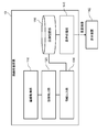
- FIG. 2 is a block diagram illustrating a hardware configuration of the road surface inspection device 10.
- the road surface inspection device 10 includes a bus 1010, a processor 1020, a memory 1030, a storage device 1040, an input / output interface 1050, and a network interface 1060.
- the bus 1010 is a data transmission path for the processor 1020, the memory 1030, the storage device 1040, the input / output interface 1050, and the network interface 1060 to transmit and receive data to and from each other.
- the method of connecting the processors 1020 and the like to each other is not limited to the bus connection.
- the processor 1020 is a processor realized by a CPU (Central Processing Unit), a GPU (Graphics Processing Unit), or the like.
- the memory 1030 is a main storage device realized by a RAM (Random Access Memory) or the like.
- the storage device 1040 is an auxiliary storage device realized by an HDD (Hard Disk Drive), an SSD (Solid State Drive), a memory card, a ROM (Read Only Memory), or the like.
- the storage device 1040 stores a program module that realizes each function of the road surface inspection device 10 (image acquisition unit 110, damage detection unit 120, information output unit 130, etc.).
- the processor 1020 reads each of these program modules into the memory 1030 and executes them, each function corresponding to each program module is realized.
- the input / output interface 1050 is an interface for connecting the road surface inspection device 10 and various input / output devices.
- An input device such as a keyboard or mouse, an output device (not shown) such as a display or a printer may be connected to the input / output interface 1050.
- an image pickup device 22 (or a portable storage medium provided in the image pickup device 22) may be connected to the input / output interface 1050.
- the road surface inspection device 10 can communicate with the image pickup device 22 (or a portable storage medium provided in the image pickup device 22) via the input / output interface 1050 to acquire the road surface image generated by the image pickup device 22. ..
- the network interface 1060 is an interface for connecting the road surface inspection device 10 to the network.
- This network is, for example, LAN (Local Area Network) or WAN (Wide Area Network).
- the method of connecting the network interface 1060 to the network may be a wireless connection or a wired connection.
- the road surface inspection device 10 can communicate with the image pickup device 22 and a video database (not shown) via the network interface 1060 to acquire the road surface video generated by the image pickup device 22.
- the hardware configuration of the road surface inspection device 10 is not limited to the configuration illustrated in FIG.
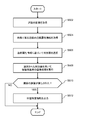
- FIG. 3 is a flowchart illustrating a flow of processing executed by the road surface inspection device 10 of the first embodiment.
- the image acquisition unit 110 acquires an image of the road to be processed (S102).
- the image acquisition unit 110 acquires the road surface image generated by the image pickup apparatus 22 via, for example, the input / output interface 1050 and the network interface 1060.
- the image acquisition unit 110 reads all or a part of the plurality of frame images constituting the road surface image as an image of the road to be processed.
- the image acquisition unit 110 may be configured to execute pre-processing on the image of the road in order to improve the efficiency of processing in the post-process.
- the image acquisition unit 110 may execute preprocessing such as front correction processing and deblurring processing on the road image.
- the damage detection unit 120 acquires information (road attribute information) indicating the attributes of the road appearing in the image to be processed acquired by the image acquisition unit 110 (S104).
- the attributes of a road are, for example, the position information of the road (for example, GPS (Global Positioning System) information), the laying environment of the road (for example, mountainous area or flat land), and the type of road surface (type of pavement material: for example. , Concrete, asphalt, gravel, bricks, cobblestones, etc.), the time elapsed since the road was laid, the traffic volume of vehicles at the location of the road, and at least one of the past damage history at the location of the road. Including. Below are some specific examples of how to get the attributes of a road. However, the method of acquiring road attributes is not limited to the examples shown below.
- the damage detection unit 120 can acquire information indicating a shooting position of the image (the position of the road reflected in the image) as road attribute information from, for example, Exif data of the image to be processed. Further, when the image acquired by the image acquisition unit 110 is associated with position information such as GPS information (information indicating the shooting position of the image), the damage detection unit 120 processes the position information. It can be acquired as road attribute information of the road shown in the image. In addition, a database (shown) that stores information indicating road attributes such as road laying environment, road surface type, road laying date and time, vehicle traffic volume, and past damage history in association with road position information. If the above is constructed, the damage detection unit 120 refers to the database based on the position information of the road shown in the image to be processed, and thereby at least one of the information indicating the above-mentioned attributes. Can be obtained.
- the damage detection unit 120 may be configured to determine the attributes of the road based on the image.
- the damage detection unit 120 may be configured to discriminate the attributes of the road (such as the laying environment and the type of road surface) appearing in the input image by using a discriminator constructed by rule base or machine learning. Good. For example, by preparing a plurality of learning data combining a road image and a label (correct answer label) indicating the environment of the road laying place and the type of road surface, and repeating machine learning using the plurality of learning data, It is possible to construct a discriminator capable of discriminating the road laying environment and the type of road surface of the road reflected in an unknown input image (road image).
- the damage detection unit 120 sets a target area for image processing for damage detection based on the acquired road attribute information (S106).
- FIG. 4 is a diagram illustrating setting rule information that defines a rule for setting a target area.
- the setting rule information exemplified in FIG. 4 defines the division of the road as the target area of the image processing for damage detection in association with the information of the section (road position).
- the setting rule information illustrated in FIG. 4 defines the division of the road as the target area of image processing for damage detection as "roadway” and "road shoulder” in section A and only "roadway” in section B, respectively.
- the setting rule information as shown in FIG. 4 is input in advance by, for example, a road manager or an inspection company that undertakes inspection work, and is stored in a storage area (memory 1030, storage device 1040, etc.) of the road surface inspection device 10. Will be done.
- the damage detection unit 120 sets the “road” and “road” based on the setting rule information exemplified in FIG. A road division called "road shoulder” is specified, and the pixel area corresponding to the "roadway” and “road shoulder” is set as a target area for image processing for damage detection.
- the damage detection unit 120 classifies the road as "road” based on the setting rule information exemplified in FIG.
- the pixel area corresponding to the specified "roadway” is set as the target area of image processing for damage detection.
- a setting rule may be provided in which the division of the roadway is subdivided into lane units.
- FIG. 17 is a diagram showing another example of setting rule information that defines a rule for setting a target area.
- the damage detection unit 120 sets the "traveling lane” and the "oncoming lane” based on the setting rule information exemplified in FIG. ”And“ shoulder ”to identify the road divisions. Then, the damage detection unit 120 sets the pixel areas corresponding to the “traveling lane”, the “oncoming lane”, and the “road shoulder” as the target areas for image processing for damage detection. Further, when the position information of the road acquired as the road attribute information indicates the position included in the section B, the damage detection unit 120 divides the road as "traveling lane” based on the setting rule information exemplified in FIG. To identify.
- the damage detection unit 120 sets the pixel area corresponding to the “traveling lane” as the target area for image processing for damage detection. Further, when the position information of the road acquired as the road attribute information indicates the position included in the section C, the damage detection unit 120 sets the "traveling lane” and the “passing lane” based on the setting rule information exemplified in FIG. Identify the road division called "lane”. Then, the damage detection unit 120 sets the pixel area corresponding to the “traveling lane” and the “passing lane” as the target area for image processing for damage detection.
- the damage detection unit 120 sets the "first lane” and "1st lane” based on the setting rule information exemplified in FIG. Identify the road categories of "second driving lane” and "passing lane”. Then, the damage detection unit 120 sets the pixel area corresponding to the “first traveling lane”, the “second traveling lane”, and the “passing lane” as the target area for image processing for damage detection.
- the damage detection unit 120 includes "oncoming lane", “traveling lane (first traveling lane / second traveling lane)", based on detection positions of marks such as the center line of the road, the boundary line of the lane, and the outside line of the road. It is possible to specify the pixel area corresponding to the classification such as "passing lane” and "road shoulder”.
- the damage detection unit 120 when the damage detection unit 120 acquires the road attribute information indicating the road laying environment, the damage detection unit 120 can set the target area according to the laying environment indicated by the road attribute information.
- the damage detection unit 120 acquires the road attribute information indicating that the road laying environment is such a section, for example, the area including the area outside the road outer line is image-processed for damage detection.
- the damage detection unit 120 acquires as road attribute information that the road laying environment is a section for which only the roadway is a damage detection target, for example, the area inside the roadway outer line is image-processed for damage detection. Set as the target area of.
- the damage detection unit 120 when the damage detection unit 120 acquires the road attribute information indicating the type of the road surface, the damage detection unit 120 is based on the type of the road surface indicated by the road attribute information and the judgment criteria set by the road manager or the inspection company. Therefore, the target area for image processing for damage detection can be set.
- a road manager or an inspection company may inspect only a predetermined type of road surface.
- road managers and inspection companies only inspect road surfaces paved with asphalt or concrete, not road surfaces paved with other materials such as gravel (gravel roads). Such a case is also conceivable.
- the damage detection unit 120 sets the target area when the type of the road surface indicated by the road attribute information is asphalt pavement or concrete pavement, and sets the target area when it is another type such as gravel (gravel road). Do not set as (not to be detected).
- the damage detection unit 120 when the damage detection unit 120 acquires the road attribute information indicating the traffic volume of the road, the damage detection unit 120 sets a target area for image processing for damage detection according to the traffic volume indicated by the road attribute information. Can be done. For example, the damage detection unit 120 sets the roadway and the shoulder as the target area in the section where the traffic volume is heavy (the traffic volume exceeds a predetermined threshold value), and the section where the traffic volume is low (the traffic volume exceeds a predetermined threshold value). Only the roadway can be set as the target area for image processing for damage detection.
- the damage detection unit 120 can determine a target area for image processing for damage detection based on the past damage history.
- the damage detection unit 120 is for damage detection so as to include both the area inside the roadway outer line (roadway area) and the area outside the roadway outside line (for example, the area of the road shoulder or the ground on the side of the road). Set the target area for image processing.
- the damage detection unit 120 can specify an area corresponding to a road division such as "roadway” or "shoulder” from the image, for example, as follows. First, the damage detection unit 120 detects predetermined marks (lane markings, road markings, curbs, guardrails, etc.) for identifying the road area from the image to be processed. In this case, the damage detection unit 120 can use, for example, an algorithm for detecting a mark on the road, which is known in the field of automatic driving technology and the like. Then, the damage detection unit 120 determines the area corresponding to the road based on the detection position of the predetermined mark. In some cases, a predetermined mark such as a road outside line cannot be detected in the image to be processed.
- predetermined marks latitude, road markings, curbs, guardrails, etc.
- the damage detection unit 120 determines the road area and the ground area outside the road based on, for example, the color features that can be extracted from the image, or the road area and the ground outside the road by machine learning. It may be configured to determine the area of the road using a discriminator constructed so that the boundary with the area can be discriminated. After the road area is determined, the damage detection unit 120 divides the road area into a plurality of areas (roadway area, shoulder area, sidewalk area, etc.) in the width direction. Then, the damage detection unit 120 uses the result of dividing the road shown in the image into a plurality of regions (for example, a roadway, a shoulder, a sidewalk, etc.) in the width direction of the road, and sets a target region for image processing for damage detection.
- a discriminator constructed so that the boundary with the area can be discriminated.
- the damage detection unit 120 executes image processing for damage detection on the set target area (S108). As a result of this image processing, it is determined whether or not the road shown in the image to be processed has damage.
- the information output unit 130 outputs position identification information capable of identifying the position of the damaged road (S112).
- the information output unit 130 can acquire, for example, information indicating a shooting position of an image included in Exif data, a frame number of an image to be processed in a road surface image, and the like as position identification information.
- the information output unit 130 lists the position information generated based on the image processing result of each image included in the road surface image in a predetermined format (for example, CSV (Comma Separated Values) format). Output to a storage area such as memory 1030 or storage device 1040. Further, the information output unit 130 may be configured to display and output a list of position identification information on a display (not shown).
- a target area for image processing for damage detection is set based on the attributes of the road appearing in the image to be processed.
- image processing for damage detection is executed for the set target area.
- the position identification information capable of identifying the position where the damage to the road is detected by the image processing is output. A person engaged in road inspection work can easily grasp the position of a damaged road by referring to this position identification information.
- the road surface inspection device 10 of the present embodiment has the same configuration as that of the first embodiment except for the points described below.
- the damage detection unit 120 is configured to switch the discriminator (processing logic for detecting road damage) used in the image processing for damage detection based on the attributes of the road appearing in the image. Will be done.
- FIG. 5 is a diagram illustrating the functional configuration of the road surface inspection device 10 of the second embodiment.
- the road surface inspection device 10 has a discriminator (processing logic) for each type of road surface, and the damage detection unit 120 performs image processing according to the type of road surface of the road shown in the image to be processed. It is configured to switch the discriminator used.
- the road surface inspection device 10 is a first discriminator 1202 specially constructed for damage to a road surface paved with asphalt, and a first discriminator 1202 specially constructed for damage to a road surface paved with concrete. It has two discriminators 1204.
- a discriminator specialized for other types of road surface damage such as cobblestones and gravel may be further prepared.
- a discriminator corresponding to other attributes such as a road laying environment and traffic volume may be further prepared.
- FIG. 6 is a flowchart illustrating a flow of processing executed by the road surface inspection device 10 of the second embodiment.
- the flowchart of the present embodiment is different from the flowchart of FIG. 3 in that the process of S202 is further included.
- the damage detection unit 120 selects a discriminator (processing logic) to be used in image processing based on the road attribute information acquired in the processing of S104 (S202). For example, when the road attribute information indicating that the road surface type is asphalt is acquired, the damage detection unit 120 selects the first discriminator 1202 as the discriminator used in the image processing. Then, in the process of S108, the damage detection unit 120 executes image processing using the discriminator selected in the process of S202 on the target area set in the process of S106.
- a discriminator processing logic
- a plurality of discriminators are prepared according to the attributes of the road, and the discriminators corresponding to the attributes of the road appearing in the image to be processed are used. Image processing is executed.
- image processing for damage detection using a discriminator (processing logic) suitable for the attributes of the road, the effect of improving the accuracy of detecting damage on the road can be obtained.
- the type of damage present on the road is the information needed to determine the repair work to be done later.
- the damage detection unit 120 is configured to further identify the type of damage detected in the image processing.
- the information output unit 130 is configured to further output information indicating the type of road damage detected in the image processing in association with the position identification information.
- FIG. 7 is a diagram illustrating the functional configuration of the road surface inspection device 10 according to the third embodiment.
- the damage detection unit 120 includes a discriminator 1206 constructed to output information indicating the type of damage detected in the image processing.
- the discriminator 1206 uses, for example, learning data that combines a learning image with a correct label indicating the type of damage present in the image (cracks, rutting, potholes, depressions, depressions, steps, etc.). By repeating machine learning, the type of damage can be identified.
- FIG. 8 is a flowchart illustrating a flow of processing executed by the road surface inspection device 10 of the third embodiment.
- the process of S302 in the flowchart of the present embodiment is different from the flowchart of FIG.
- the information output unit 130 when road damage is detected in the image processing of S108, the information output unit 130 outputs information including information indicating the type of the detected damage and position identification information (S302).
- the information output unit 130 outputs CSV format data including, for example, position identification information and information indicating the type of damage (for example, code information assigned to each type of damage) in one record.
- the position identification information that can identify the position of the damaged road and the information indicating the type of damage detected at that position are output.
- a person involved in road maintenance and inspection work can easily understand what kind of repair measures are required at which position by checking the location identification information and the information indicating the type of damage to the road. be able to.
- the information output unit 130 calculates a score (degree of damage) for each type of damage identified in the image processing, and further outputs information indicating the score calculated for each type of damage. It may be configured in. For example, the information output unit 130 adds up the area (number of pixels) of the image area in which damage is detected for each type of damage, and determines the degree of damage as the ratio of the total area to the area of the target area for image processing. It may be configured to be calculated and output as information to be shown. Persons involved in road maintenance and inspection work will be able to appropriately prioritize repair work based on information indicating the type of damage and the degree of damage.
- the urgency of repair may differ depending on the type and location of damage.
- a pothole is more likely to have an adverse effect on the passage of vehicles and people than a crack, and can be said to be an urgent damage for repair.
- the former position is more likely to adversely affect the passing vehicle or person, and repair is urgent. It can be said that the damage is highly sexual. Therefore, the information output unit 130 may be configured to calculate the degree of damage by weighting according to the type and position of the detected damage.
- the information output unit 130 is configured to calculate the degree of damage by using a weighting coefficient defined in advance for each type of damage and a weighting coefficient determined according to the damage detection position.
- the "degree of damage" output from the information output unit 130 becomes information that more accurately indicates the urgency of repair. That is, the "degree of damage” output from the information output unit 130 becomes more useful information for the person who performs the maintenance and inspection work of the road. For example, a person who performs road maintenance and inspection work can make an efficient plan, such as prioritizing more effective repair work based on the "degree of damage" output from the information output unit 130. It will be possible.
- the present embodiment has the same configuration as any one of the first embodiment, the second embodiment, and the third embodiment except for the points described below.
- FIG. 9 is a diagram illustrating the functional configuration of the road surface inspection device 10 according to the fourth embodiment.
- the road surface inspection device 10 of the present embodiment further includes a display processing unit 140 and an image storage unit 150.
- the display processing unit 140 displays the superimposed image on the display device 142 connected to the road surface inspection device 10.
- the superimposed image is an image in which information indicating the position of damage on the road detected by image processing is superimposed on the image of the road, and is generated by, for example, the information output unit 130.
- the information output unit 130 identifies an area where damage is located in an image of a road to be processed based on the result of image processing executed by the damage detection unit 120, and superimposes the position of the area so that it can be distinguished. Generate data. Then, the information output unit 130 generates a superposed image by superimposing the superposed data on the image of the road.
- the information output unit 130 stores the generated superimposed image in the image storage unit 150 (for example, a memory 1030, a storage device 1040, etc.) in association with the position identification information. For example, when the display processing unit 140 receives an input for designating the position identification information corresponding to the image to be displayed, the display processing unit 140 reads the superimposed image stored in association with the designated position correspondence information from the image storage unit 150 and displays it. Displayed on the device 142.
- the image storage unit 150 for example, a memory 1030, a storage device 1040, etc.
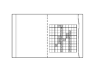
- ⁇ Display example of superimposed image> 10 to 14 are views showing an example of a superimposed image displayed by the display processing unit 140 of the fourth embodiment. It should be noted that these figures are examples, and do not limit the content of the invention of the present embodiment.
- the superimposed image illustrated in FIG. 10 includes a display element on the square indicating the target area and a display element highlighting the square corresponding to the position where the damage is detected. With such a superposed image, it is possible to grasp at a glance which position is damaged.
- the display processing unit 140 may perform front correction processing when displaying the superimposed image.
- a superposed image of the road as seen from above is displayed on the display device 142 as shown in FIG. According to the image as illustrated in FIG. 11, the magnitude of damage can be accurately grasped.
- the front correction process may be performed by the information output unit 130 when the superimposed image is generated.
- the superimposed image may include information indicating the degree of damage (“damage rate” in the example of this figure).
- the information output unit 130 calculates the degree of damage based on the size of the target area for image processing (the number of squares and the number of pixels) and the size of the damaged area, and superimposes the calculation result. Is stored in the image storage unit 150 in association with the above. Then, when displaying the superimposed image, the display processing unit 140 reads out the information indicating the degree of damage together with the superimposed image and displays it at a predetermined display position.
- the information output unit 130 may be configured to calculate the degree of damage for each road category. In this case, as shown in FIG. 13, for example, the display processing unit 140 displays information indicating the degree of damage at a position corresponding to each road division (“roadway”, “shoulder”, etc.).
- the score for each type of damage is as shown in FIG. A superposed image containing information indicating the above may be generated. With such a superimposed image, it is possible to easily grasp what kind of damage is at which position on the road. For example, according to the superimposed image illustrated in FIG. 14, in the area of the roadway, there are cracks showing 19% of the area, potholes occupying 6% of the area, and the area of the shoulder. It can be easily grasped that there is a pothole that occupies 10% of the area.
- a person who performs road maintenance and inspection work can easily confirm the damaged state of the damaged road.
- the road surface inspection device 10 of the present embodiment is different from each of the above-described embodiments in the points described below.
- FIG. 15 is a diagram illustrating the functional configuration of the road surface inspection device 10 according to the fifth embodiment.
- the damage detection unit 120 of the present embodiment has a plurality of determination devices (image processing processing logic for detecting damage on the road surface).
- the damage detection unit 120 of the present embodiment selects a determination device corresponding to the attribute from a plurality of determination devices based on the attribute of the road shown in the image. Then, the damage detection unit 120 of the present embodiment executes image processing for damage detection using the selected determination device.
- the damage detection unit 120 of the present embodiment does not have the function of setting the target area for image processing based on the road attribute information as described in each of the above-described embodiments.
- the hardware configuration is the same as in FIG.
- the storage device 1040 stores a program module for realizing the above-mentioned function of the damage detection unit 120 instead of the program module for realizing the function of the damage detection unit 120. Further, when the processor 1020 reads this program into the memory 1030 and executes it, the function of the damage detection unit 120 described above is realized.
- FIG. 16 is a flowchart illustrating a flow of processing executed by the road surface inspection device 10 of the fifth embodiment.
- the image acquisition unit 110 acquires an image of the road to be processed (S502).
- the damage detection unit 120 acquires information (road attribute information) indicating the attributes of the road appearing in the image to be processed acquired by the image acquisition unit 110 (S504).
- the processing of S502 and S504 is the same as the processing of S102 and S104 of FIG. 3, respectively.
- the damage detection unit 120 selects a discriminator corresponding to the road attribute information of the road shown in the image to be processed from a plurality of discriminators prepared for each attribute (S506). For example, when the road attribute information indicating that the road surface type is "asphalt" is acquired, the damage detection unit 120 selects a discriminator specially constructed for "asphalt". Then, the damage detection unit 120 executes image processing for damage detection using the selected discriminator (S508). As a result of this image processing, it is determined whether or not the road shown in the image to be processed has damage.
- the information output unit 130 When damage is detected by image processing (S510: YES), the information output unit 130 generates and outputs position identification information capable of identifying the position of the damaged road (S512).
- the processing of S510 and S512 is the same as the processing of S110 and S112 of FIG. 3, respectively.
- the image processing for damage detection is executed by using the processing logic corresponding to the road attribute information of the road reflected in the image to be processed. That is, the image processing for damage detection is executed by using the processing logic specialized for the attribute of the road shown in the image. By doing so, it is possible to improve the accuracy of detecting damage caused by image processing.
- Image acquisition means to acquire an image of the road
- a damage detection means that sets a target area in the image of the image processing for detecting damage to the road based on the attributes of the road reflected in the image, and performs the image processing on the set target area.
- An information output means for outputting position identification information capable of identifying the position of the road where damage was detected by the image processing, and A road surface inspection device equipped with.
- the damage detecting means detects a region corresponding to a road from the image and sets the target region in the detected region. 1. 1. The road surface inspection device described in. 3. 3.
- the damage detecting means is The road shown in the image is divided into a plurality of areas in the width direction of the road.
- the target area is set using the result of dividing the road into a plurality of areas.
- the road attributes include at least one of location information, laying environment, road surface type, elapsed time since the road was laid, vehicle traffic, and past damage history. 1. 1. From 3.
- the attribute of the road is the position information of the road.
- the damage detecting means sets the target area based on the area setting rule associated with the position information of the road in advance. 4.
- the damage detecting means determines the attributes of the road based on the image. 1. 1. From 5.
- the damage detecting means switches the processing logic used in the image processing based on the attributes of the road. 1. 1. From 6. The road surface inspection device according to any one of the above. 8. The attribute of the road is the type of road surface of the road. The damage detecting means determines the processing logic used in the image processing based on the type of the road surface. 7. The road surface inspection device described in. 9. The damage detecting means further identifies the type of road damage in the image processing and The information output means further outputs information indicating the type of damage to the road detected by the image processing. 1. 1. From 8. The road surface inspection device according to any one of the above. 10. The information output means calculates the degree of damage for each type of damage on the identified road, and further outputs information indicating the degree of damage calculated for each type of damage. 9.
- the position-specific information includes at least one of the latitude / longitude information of the road and the frame number of the image. 1. 1.
- To 10. The road surface inspection device according to any one of the above. 12.
- a display processing means for displaying on a display device a superimposed image in which information indicating the position of road damage detected by the image processing is superimposed on the image is further provided. 1. 1. From 11.
- the road surface inspection device according to any one of the above. 13 The computer Get an image of the road and The target area in the image of the image processing for detecting the damage of the road is set based on the attribute of the road reflected in the image. The image processing is performed on the set target area, and the image processing is performed.
- Road surface inspection method including that. 14.
- the computer A region corresponding to a road is detected from the image, and the target region is set in the detected region. Including 13.
- the computer The road shown in the image is divided into a plurality of areas in the width direction of the road. The target area is set using the result of dividing the road into a plurality of areas. Including 14.
- the road attributes include at least one of location information, laying environment, road surface type, elapsed time since the road was laid, vehicle traffic, and past damage history. 13. To 15. The road surface inspection method according to any one of the above. 17.
- the attribute of the road is the position information of the road.
- the computer The target area is set based on the area setting rule associated with the position information of the road in advance. Including 16. Road surface inspection method described in. 18.
- the computer Judging the attributes of the road based on the image, Including 13. From 17.
- the computer The processing logic used in the image processing is switched based on the attributes of the road. Including 13. To 18.
- the attribute of the road is the type of road surface of the road.
- the computer The processing logic used in the image processing is determined based on the type of the road surface. Including that 19. Road surface inspection method described in. 21.
- the computer The type of road damage was further identified in the image processing.
- Image acquisition means to acquire an image of the road
- a damage detection means that selects an image processing processing logic for detecting damage to the road surface based on the attributes of the road shown in the image, and performs image processing on the image using the selected processing logic.
- An information output means for outputting position identification information capable of identifying the position of the road where damage was detected by the image processing, and A road surface inspection device equipped with.
Abstract
路面検査装置(10)は、画像取得部(110)、損傷検出部(120)、および情報出力部(130)を備える。画像取得部(110)は、道路が写る画像を取得する。損傷検出部(120)は、道路の損傷を検出するための画像処理の前記画像における対象領域を、前記画像に写る道路の属性に基づいて設定し、設定された前記対象領域に対して前記画像処理を行う。情報出力部(130)は、前記画像処理によって損傷が検出された道路の位置を特定可能な位置特定情報を出力する。
Description
本発明は、敷設された道路路面の管理業務を支援する技術に関する。
道路は車両の通行や経年などによって劣化する。その結果、道路の路面に損傷が発生し得る。道路の損傷をそのままにしておくと事故の原因になり得る。そのため、道路は定期的に点検する必要がある。
道路の点検を効率よく行うための技術の一例が、下記特許文献1に開示されている。下記特許文献1には、道路の画像を用いて、その道路の路面の損傷(ひび割れ、轍掘れなど)を検出する技術の一例が開示されている。
一般的に、画像処理によってコンピュータに係る負荷は大きい。特許文献1に開示される技術のように、道路の画像を用いて点検を行う場合、コンピュータが道路の画像を大量に処理することになる。その結果、コンピュータでの処理時間が長くなり、業務の効率が低下し得る。業務の効率を改善させるために、コンピュータでの処理を高速化させる技術が望まれる。
本発明は、上記の課題に鑑みてなされたものである。本発明の目的の一つは、道路の画像を用いて道路を点検する際、コンピュータによる画像の処理速度を向上させる技術を提供することである。
本発明の路面検査装置は、
道路が写る画像を取得する画像取得手段と、
道路の損傷を検出するための画像処理の前記画像における対象領域を、前記画像に写る道路の属性に基づいて設定し、設定された前記対象領域に対して前記画像処理を行う損傷検出手段と、
前記画像処理によって損傷が検出された道路の位置を特定可能な位置特定情報を出力する情報出力手段と、
を備える。
道路が写る画像を取得する画像取得手段と、
道路の損傷を検出するための画像処理の前記画像における対象領域を、前記画像に写る道路の属性に基づいて設定し、設定された前記対象領域に対して前記画像処理を行う損傷検出手段と、
前記画像処理によって損傷が検出された道路の位置を特定可能な位置特定情報を出力する情報出力手段と、
を備える。
本発明の路面検査方法は、
コンピュータが、
道路が写る画像を取得し、
道路の損傷を検出するための画像処理の前記画像における対象領域を、前記画像に写る道路の属性に基づいて設定し、
設定された前記対象領域に対して前記画像処理を行い、
前記画像処理によって損傷が検出された道路の位置を特定可能な位置特定情報を出力する、
ことを含む。
コンピュータが、
道路が写る画像を取得し、
道路の損傷を検出するための画像処理の前記画像における対象領域を、前記画像に写る道路の属性に基づいて設定し、
設定された前記対象領域に対して前記画像処理を行い、
前記画像処理によって損傷が検出された道路の位置を特定可能な位置特定情報を出力する、
ことを含む。
本発明のプログラムは、コンピュータに上述の路面検査方法を実行させる。
本発明によれば、道路の画像を用いて道路を点検する際、コンピュータによる画像の処理速度を向上させる技術が提供される。
上述した目的、およびその他の目的、特徴および利点は、以下に述べる好適な実施の形態、およびそれに付随する以下の図面によってさらに明らかになる。
以下、本発明の実施形態について、図面を用いて説明する。尚、すべての図面において、同様の構成要素には同様の符号を付し、説明を適宜省略する。また、特に説明する場合を除き、各ブロック図において、各ブロックは、ハードウエア単位の構成ではなく、機能単位の構成を表している。また、図中の矢印の向きは、情報の流れを分かり易くするためのものであり、特に説明のない限り通信の方向(一方向通信/双方向通信)を限定しない。
[第1実施形態]
<機能構成例>
図1は、第1実施形態における路面検査装置10の機能構成を例示する図である。図1に示されるように、本実施形態に係る路面検査装置10は、画像取得部110、損傷検出部120、および情報出力部130を備える。
<機能構成例>
図1は、第1実施形態における路面検査装置10の機能構成を例示する図である。図1に示されるように、本実施形態に係る路面検査装置10は、画像取得部110、損傷検出部120、および情報出力部130を備える。
画像取得部110は、点検対象の路面が写る画像を取得する。図1に例示されるように、路面の画像は、車両20に備えられた撮像装置22によって生成される。具体的には、車両20が点検対象区間の道路を走行している間に、撮像装置22が撮影動作を行うことによって、点検対象区間の道路の路面映像が生成される。画像取得部110は、路面映像を構成する複数のフレーム画像の少なくとも1つを、画像処理(解析)対象の画像として取得する。撮像装置22がインターネット等のネットワークに接続する機能を備えている場合、画像取得部110は、ネットワークを介して撮像装置22から路面の画像を取得してもよい。また、ネットワークに接続する機能を備える撮像装置22が、路面映像を図示しない映像データベースに送信し、画像取得部110は、当該映像データベースにアクセスして路面映像を取得するように構成されていてもよい。また、画像取得部110は、例えば、通信ケーブルによって接続された撮像装置22、あるいは、メモリカードなどの可搬型記憶媒体から、路面映像を取得してもよい。
損傷検出部120は、画像取得部110が取得した路面の画像について、その画像に写る道路の属性に基づいて、道路の損傷を検出するための画像処理の対象とする領域(以下、「対象領域」と表記)を設定する。そして、損傷検出部120は、設定された対象領域に対して、道路の損傷を検出するための画像処理を行う。画像処理によって検出される道路の損傷は、例えば、路面に生じたひび割れ、わだち掘れ、ポットホール、陥没、窪み、および段差などである。
情報出力部130は、損傷検出部120により道路の損傷が検出された場合、その損傷が検出された位置を特定可能な情報(以下、「位置特定情報」とも表記)を生成および出力する。なお、情報出力部130は、処理対象の画像のメタデータ(例えば、Exif(Exchangeable Image File Format)など)に含まれる当該画像の撮影位置(緯度および経度)を示す情報(すなわち、道路の緯度および経度を示す情報)を、位置特定情報として利用することができる。また、画像取得部110が、画像と共に位置データを取得している場合、情報出力部130は、当該画像と共に取得された位置データを、位置特定情報として利用することができる。また、処理対象の画像に写る道路の位置は、映像データのフレーム番号から推測することもできる。例えば、ある区間を走行した結果として、36000フレームで構成される映像が得られた場合、18000番目のフレームは、その区間の中間地点の近傍と推測することができる。また、車両20の走行時の制御データが取得できている場合、この制御データを更に用いることによって、フレーム画像の撮影位置(道路の位置)をより高い精度で推定することができる。よって、情報出力部130は、処理対象の画像のフレーム番号を位置特定情報として利用してもよい。この場合、情報出力部130は、道路の緯度経度情報および1つの映像データにおけるフレーム番号の少なくとも一方を含む位置特定情報を生成および出力する。また、損傷検出部120が、撮影位置を特定可能な特定の物体(例:キロポスト、番地や道路名を示す標識など)を画像処理において更に認識するように構成されており、情報出力部130が、当該特定の物体の認識結果から得られる情報(キロポストの数字、標識に記載された番地や道路名など)を位置特定情報として利用するように構成されていてもよい。
<ハードウエア構成例>
路面検査装置10の各機能構成部は、各機能構成部を実現するハードウエア(例:ハードワイヤードされた電子回路など)で実現されてもよいし、ハードウエアとソフトウエアとの組み合わせ(例:電子回路とそれを制御するプログラムの組み合わせなど)で実現されてもよい。以下、ハードウエアとソフトウエアとの組み合わせで路面検査装置10の各機能構成部を実現する場合について、図2を用いてさらに説明する。図2は、路面検査装置10のハードウエア構成を例示するブロック図である。
路面検査装置10の各機能構成部は、各機能構成部を実現するハードウエア(例:ハードワイヤードされた電子回路など)で実現されてもよいし、ハードウエアとソフトウエアとの組み合わせ(例:電子回路とそれを制御するプログラムの組み合わせなど)で実現されてもよい。以下、ハードウエアとソフトウエアとの組み合わせで路面検査装置10の各機能構成部を実現する場合について、図2を用いてさらに説明する。図2は、路面検査装置10のハードウエア構成を例示するブロック図である。
路面検査装置10は、バス1010、プロセッサ1020、メモリ1030、ストレージデバイス1040、入出力インタフェース1050、及びネットワークインタフェース1060を有する。
バス1010は、プロセッサ1020、メモリ1030、ストレージデバイス1040、入出力インタフェース1050、及びネットワークインタフェース1060が、相互にデータを送受信するためのデータ伝送路である。ただし、プロセッサ1020などを互いに接続する方法は、バス接続に限定されない。
プロセッサ1020は、CPU(Central Processing Unit) やGPU(Graphics Processing Unit)などで実現されるプロセッサである。
メモリ1030は、RAM(Random Access Memory)などで実現される主記憶装置である。
ストレージデバイス1040は、HDD(Hard Disk Drive)、SSD(Solid State Drive)、メモリカード、又はROM(Read Only Memory)などで実現される補助記憶装置である。ストレージデバイス1040は路面検査装置10の各機能(画像取得部110、損傷検出部120、情報出力部130など)を実現するプログラムモジュールを記憶している。プロセッサ1020がこれら各プログラムモジュールをメモリ1030上に読み込んで実行することで、各プログラムモジュールに対応する各機能が実現される。
入出力インタフェース1050は、路面検査装置10と各種入出力デバイスとを接続するためのインタフェースである。入出力インタフェース1050には、キーボードやマウスといった入力装置(図示せず)、ディスプレイやプリンタといった出力装置(図示せず)などが接続され得る。また、入出力インタフェース1050には、撮像装置22(または、撮像装置22に備えられた可搬型記憶媒体)が接続され得る。路面検査装置10は、入出力インタフェース1050を介して撮像装置22(または、撮像装置22に備えられた可搬型記憶媒体)と通信し、撮像装置22によって生成された路面映像を取得することができる。
ネットワークインタフェース1060は、路面検査装置10をネットワークに接続するためのインタフェースである。このネットワークは、例えばLAN(Local Area Network)やWAN(Wide Area Network)である。ネットワークインタフェース1060がネットワークに接続する方法は、無線接続であってもよいし、有線接続であってもよい。路面検査装置10は、ネットワークインタフェース1060を介して、撮像装置22や図示しない映像データベースと通信し、撮像装置22によって生成された路面映像を取得することができる。
なお、路面検査装置10のハードウエア構成は図2に例示される構成に限定されない。
<処理の流れ>
図3は、第1実施形態の路面検査装置10により実行される処理の流れを例示するフローチャートである。
図3は、第1実施形態の路面検査装置10により実行される処理の流れを例示するフローチャートである。
まず、画像取得部110は、処理対象となる道路の画像を取得する(S102)。画像取得部110は、例えば、入出力インタフェース1050やネットワークインタフェース1060を介して、撮像装置22によって生成された路面映像を取得する。そして、画像取得部110は、路面映像を構成する複数のフレーム画像の全部または一部を、処理対象の道路の画像として読み込む。ここで、画像取得部110は、後工程での処理を効率化するために、道路の画像に対して前処理を実行するように構成されていてもよい。例えば、画像取得部110は、道路の画像に対して、正面補正処理やデブラーリング処理などの前処理を実行してもよい。
次に、損傷検出部120は、画像取得部110により取得された処理対象の画像に写る道路の属性を示す情報(道路属性情報)を取得する(S104)。道路の属性は、例えば、その道路の位置情報(例えば、GPS(Global Positioning System)情報など)、その道路の敷設環境(例えば、山間部や平地など)、路面の種類(舗装材料の種類:例えば、コンクリート、アスファルト、砂利、レンガ、石畳など)、その道路が敷設されてからの経過時間、その道路の位置における車両の交通量、および、その道路の位置における過去の損傷履歴の少なくとも1つを含む。以下に、道路の属性を取得する方法の具体例をいくつか示す。但し、道路の属性の取得方法は、以下に示す例に制限されない。
損傷検出部120は、例えば処理対象の画像のExifデータなどから、その画像の撮影位置(その画像に写る道路の位置)を示す情報を、道路属性情報として取得することができる。また、画像取得部110が取得した画像について、GPS情報などの位置情報(その画像の撮影位置を示す情報)が紐づけられている場合、損傷検出部120は、その位置情報を、処理対象の画像に写る道路の道路属性情報として取得することができる。また、道路の敷設環境、路面の種類、道路の敷設日時、車両の交通量、および、過去の損傷履歴といった道路の属性を示す情報を、道路の位置情報と対応付けて記憶するデータベース(図示せず)が構築されていれば、損傷検出部120は、処理対象の画像に写る道路の位置情報に基づいて当該データベースを参照することによって、上述したような属性を示す情報の少なくともいずれか1つを取得することができる。
また、損傷検出部120は、画像に基づいて道路の属性を判定するように構成されていてもよい。例えば、損傷検出部120は、ルールベース或いは機械学習によって構築された判別器を使って、入力された画像に写る道路の属性(敷設環境や路面の種類など)を判別するように構成されてもよい。例えば、道路の画像と当該道路の敷設場所の環境や路面の種類を示すラベル(正解ラベル)とを組み合わせた学習データを複数用意し、当該複数の学習データを用いて機械学習を繰り返すことで、未知の入力画像(道路の画像)に写る道路の敷設環境や当該道路の路面の種類を判別可能な判別器を構築することができる。
次に、損傷検出部120は、取得した道路属性情報に基づいて、損傷検出用の画像処理の対象領域を設定する(S106)。
一例として、損傷検出部120は、道路の位置情報を示す道路属性情報を取得した場合、例えば図4に示されるような対象領域の設定ルールを参照して、損傷検出用の画像処理の対象領域を当該道路の位置情報に応じて設定することができる。図4は、対象領域を設定するルールを定義する設定ルール情報を例示する図である。図4に例示される設定ルール情報は、損傷検出用の画像処理の対象領域とする道路の区分を、区間(道路の位置)の情報に紐付けて定義している。図4に例示される設定ルール情報は、損傷検出用の画像処理の対象領域とする道路の区分を、区間Aでは「車道」および「路肩」と、区間Bでは「車道」のみとそれぞれ定義している。なお、図4に示されるような設定ルール情報は、例えば、道路管理者や点検業務を請負う点検事業者によって予め入力され、路面検査装置10の記憶領域(メモリ1030やストレージデバイス1040など)に記憶される。ここで、例えば、道路属性情報として取得された道路の位置情報が区間Aに含まれる位置を示す場合、損傷検出部120は、図4に例示される設定ルール情報に基づいて「車道」および「路肩」という道路の区分を特定し、その「車道」および「路肩」に対応する画素領域を、損傷検出用の画像処理の対象領域に設定する。また、道路属性情報として取得された道路の位置情報が区間Bに含まれる位置を示す場合、損傷検出部120は、図4に例示される設定ルール情報に基づいて「車道」という道路の区分を特定し、その「車道」に対応する画素領域を、損傷検出用の画像処理の対象領域に設定する。なお、図17に例示されるように、車道の区分を車線単位に細分化した設定ルールが設けられていてもよい。図17は、対象領域を設定するルールを定義する設定ルール情報の他の一例を示す図である。例えば、道路属性情報として取得された道路の位置情報が区間Aに含まれる位置を示す場合、損傷検出部120は、図17に例示される設定ルール情報に基づいて「走行車線」、「対向車線」および「路肩」という道路の区分を特定する。そして、損傷検出部120は、「走行車線」、「対向車線」、および「路肩」に対応する画素領域を、損傷検出用の画像処理の対象領域に設定する。また、道路属性情報として取得された道路の位置情報が区間Bに含まれる位置を示す場合、損傷検出部120は、図17に例示される設定ルール情報に基づいて「走行車線」という道路の区分を特定する。そして、損傷検出部120は、「走行車線」に対応する画素領域を、損傷検出用の画像処理の対象領域に設定する。また、道路属性情報として取得された道路の位置情報が区間Cに含まれる位置を示す場合、損傷検出部120は、図17に例示される設定ルール情報に基づいて「走行車線」および「追越車線」という道路の区分を特定する。そして、損傷検出部120は、「走行車線」および「追越車線」に対応する画素領域を、損傷検出用の画像処理の対象領域に設定する。また、道路属性情報として取得された道路の位置情報が区間Dに含まれる位置を示す場合、損傷検出部120は、図17に例示される設定ルール情報に基づいて「第1走行車線」、「第2走行車線」、および「追越車線」という道路の区分を特定する。そして、損傷検出部120は、「第1走行車線」、「第2走行車線」、および「追越車線」に対応する画素領域を、損傷検出用の画像処理の対象領域に設定する。なお、損傷検出部120は、例えば車道中央線、車線境界線、車道外側線といった目印の検出位置に基づいて、「対向車線」、「走行車線(第1走行車線/第2走行車線)」、「追越車線」、「路肩」といった区分に対応する画素領域を特定することができる。
他の一例として、損傷検出部120は、道路の敷設環境を示す道路属性情報を取得した場合、その道路属性情報が示す敷設環境に応じた対象領域を設定することができる。具体的な例として、交通量が多い道路や降雨等により道路の端の部分やその外側の領域(例えば、路肩や道路に隣接する地面の領域など)の損傷劣化が激しい区間がある。よって、損傷検出部120は、道路の敷設環境がそのような区間であることを示す道路属性情報を取得した場合、例えば車道外側線の外側の領域を含む領域を、損傷検出用の画像処理の対象領域として設定する。また、損傷検出部120は、道路の敷設環境が車道のみを損傷検出対象とする区間であることを道路属性情報として取得した場合、例えば車道外側線の内側の領域を、損傷検出用の画像処理の対象領域として設定する。
他の一例として、損傷検出部120は、路面の種類を示す道路属性情報を取得した場合、その道路属性情報が示す路面の種類と、道路管理者や点検事業者が設けた判断基準とに基いて、損傷検出用の画像処理の対象領域を設定することができる。例えば、道路管理者や点検事業者が、予め決められた種類の路面のみを対象として点検を行うこともある。具体的な例として、道路管理者や点検事業者が、アスファルトまたはコンクリートで舗装された路面のみを点検の対象とし、グラベル(砂利道)といったその他の材料で舗装された路面を点検の対象としないといったケースも考えられる。この場合、損傷検出部120は、道路属性情報によって示される路面の種類がアスファルト舗装やコンクリート舗装である場合は対象領域として設定し、グラベル(砂利道)等のその他の種類である場合は対象領域として設定しない(検出対象としない)。
他の一例として、損傷検出部120は、道路の交通量を示す道路属性情報を取得した場合、その道路属性情報が示す交通量に応じて、損傷検出用の画像処理の対象領域を設定することができる。例えば、損傷検出部120は、交通量が多い(交通量が所定の閾値を超える)区間は車道と路肩を対象領域として設定し、交通量が少ない(交通量が所定の閾値以下の)区間は車道のみを損傷検出用の画像処理の対象領域として設定することができる。
他の一例として、損傷検出部120は、過去の損傷履歴を示す道路属性情報を取得した場合、その過去の損傷履歴に基づいて、損傷検出用の画像処理の対象領域を決定することができる。具体的な例として、処理対象の画像に写る道路の道路属性情報として、車道外側線を境に車道/路肩双方の領域において過去に損傷が発生したことを示す情報が取得されたとする。この場合、損傷検出部120は、車道外側線の内側の領域(車道の領域)と、車道外側線の外側の領域(例えば路肩や道路脇の地面の領域)双方を含むように、損傷検出用の画像処理の対象領域を設定する。
ここで、損傷検出部120は、例えば次のようにして、画像の中から「車道」や「路肩」といった道路の区分に対応する領域を特定することができる。まず、損傷検出部120は、処理対象の画像の中から、道路領域を特定するための所定の目印(区画線、路面標示、縁石、ガードレールなど)を検出する。この場合、損傷検出部120は、例えば、自動運転技術の分野等で既知となっている、道路上の目印を検出するアルゴリズムを利用することができる。そして、損傷検出部120は、所定の目印の検出位置に基づいて、道路に対応する領域を判別する。なお、処理対象の画像において、車道外側線といった所定の目印が検出できない場合もある。この場合、損傷検出部120は、例えば画像から抽出可能な色特徴量などに基づいて道路の領域と道路外の地面の領域を決定する、或いは、機械学習によって道路の領域と道路外の地面の領域との境界を識別可能に構築した判別器を使って道路の領域を決定するように構成されていてもよい。道路の領域が判別された後、損傷検出部120は、当該道路の領域を幅方向に複数の領域(車道の領域、路肩の領域、歩道の領域など)に区分する。そして、損傷検出部120は、画像に写る道路を当該道路の幅方向に複数の領域(例えば、車道、路肩、歩道など)に区分した結果を用いて、損傷検出用の画像処理の対象領域を設定する。このように、画像の中から道路に対応する画素領域を検出し、その領域の中で画像処理の対象領域を設定することによって、道路以外の領域(例えば、周囲の背景領域)から抽出可能な特徴量によって道路の損傷が誤検出される可能性が減る。これにより、道路の損傷を検出する精度(画像処理の精度)が向上する。
次に、損傷検出部120は、設定された対象領域に対して損傷検出用の画像処理を実行する(S108)。この画像処理の結果、処理対象の画像に写る道路に損傷が存在しているか否かが判別される。
そして、画像処理によって道路の損傷が検出された場合(S110:YES)、情報出力部130は、損傷のある道路の位置を特定可能な位置特定情報を出力する(S112)。情報出力部130は、例えば、Exifデータに含まれる画像の撮影位置を示す情報や、路面映像における処理対象の画像のフレーム番号などを、位置特定情報として取得することができる。そして、情報出力部130は、路面映像に含まれる各画像の画像処理結果に基づいて生成された位置情報を所定のフォーマット(例えば、CSV(Comma Separated Values)形式など)で一覧化する。メモリ1030またはストレージデバイス1040などの記憶領域に出力する。また、情報出力部130は、位置特定情報の一覧を、図示しないディスプレイに表示出力するように構成されていてもよい。
<作用・効果の例>
本実施形態では、画像を用いて道路の損傷の有無を点検する際、まず、処理対象の画像に写る道路の属性に基づいて損傷検出用の画像処理の対象領域が設定される。そして、設定された対象領域に対して損傷検出用の画像処理が実行される。このように、画像処理の対象領域を道路属性情報に基づいて限定することにより、画像処理の高速化を図ることができる。なお、画像を用いて道路の損傷の有無を点検する場合、一般的に多数の画像を処理する必要がある。そのため、本実施形態で説明したような構成によれば、画像処理の高速化する効果をより顕著に得ることができる。また、本実施形態では、画像処理によって道路の損傷が検出された位置を特定可能な位置特定情報が出力される。道路の点検業務に携わる人物は、この位置特定情報を参照することによって、損傷がある道路の位置を容易に把握することが可能となる。
本実施形態では、画像を用いて道路の損傷の有無を点検する際、まず、処理対象の画像に写る道路の属性に基づいて損傷検出用の画像処理の対象領域が設定される。そして、設定された対象領域に対して損傷検出用の画像処理が実行される。このように、画像処理の対象領域を道路属性情報に基づいて限定することにより、画像処理の高速化を図ることができる。なお、画像を用いて道路の損傷の有無を点検する場合、一般的に多数の画像を処理する必要がある。そのため、本実施形態で説明したような構成によれば、画像処理の高速化する効果をより顕著に得ることができる。また、本実施形態では、画像処理によって道路の損傷が検出された位置を特定可能な位置特定情報が出力される。道路の点検業務に携わる人物は、この位置特定情報を参照することによって、損傷がある道路の位置を容易に把握することが可能となる。
[第2実施形態]
本実施形態の路面検査装置10は、以下で説明する点を除き、第1実施形態と同様の構成を有する。
本実施形態の路面検査装置10は、以下で説明する点を除き、第1実施形態と同様の構成を有する。
<機能構成例>
道路の位置(具体的には、当該位置に基づいて特定される、道路の敷設環境、路面の種類、交通量など)によって、発生する損傷の種類や損傷の発生のし易さなどが変わり得る。本実施形態において、損傷検出部120は、損傷検出用の画像処理において使用する判別器(道路の損傷を検出するための処理ロジック)を、その画像に写る道路の属性に基づいて切り替えるように構成される。
道路の位置(具体的には、当該位置に基づいて特定される、道路の敷設環境、路面の種類、交通量など)によって、発生する損傷の種類や損傷の発生のし易さなどが変わり得る。本実施形態において、損傷検出部120は、損傷検出用の画像処理において使用する判別器(道路の損傷を検出するための処理ロジック)を、その画像に写る道路の属性に基づいて切り替えるように構成される。
図5は、第2実施形態の路面検査装置10の機能構成を例示する図である。図5において、路面検査装置10は、路面の種類別に判別器(処理ロジック)を有しており、損傷検出部120は、処理対象の画像に写る道路の路面の種類に応じて、画像処理で使用する判別器を切り替えるように構成されている。図5の例において、路面検査装置10は、アスファルトで舗装された路面の損傷に特化して構築された第1判別器1202と、コンクリートで舗装された路面の損傷に特化して構築された第2判別器1204とを有している。なお、図示されていないが、石畳や砂利といった他の種類の路面の損傷に特化した判別器が更に用意されていてもよい。また、図示されていないが、道路の敷設環境や交通量といった他の属性に対応する判別器が更に用意されていてもよい。
<処理の流れ>
図6は、第2実施形態の路面検査装置10により実行される処理の流れを例示するフローチャートである。本実施形態のフローチャートは、S202の工程を更に含む点で、図3のフローチャートと異なっている。
図6は、第2実施形態の路面検査装置10により実行される処理の流れを例示するフローチャートである。本実施形態のフローチャートは、S202の工程を更に含む点で、図3のフローチャートと異なっている。
本実施形態において、損傷検出部120は、S104の処理で取得された道路属性情報に基づいて、画像処理で使用する判別器(処理ロジック)を選択する(S202)。例えば、路面の種類がアスファルトであることを示す道路属性情報が取得された場合、損傷検出部120は、第1判別器1202を、画像処理で使用する判別器として選択する。そして、S108の処理において、損傷検出部120は、S106の処理で設定された対象領域に対して、S202の処理で選択された判別器を用いた画像処理を実行する。
<作用・効果の例>
以上、本実施形態では、道路の属性に応じて複数の判別器(損傷検出用の画像処理の処理ロジック)が用意されており、処理対象の画像に写る道路の属性に対応する判別器を用いて画像処理が実行される。道路の属性に応じて適した判別器(処理ロジック)を用いて損傷検出用の画像処理を行うことで、道路の損傷を検出する精度を向上させる効果が得られる。
以上、本実施形態では、道路の属性に応じて複数の判別器(損傷検出用の画像処理の処理ロジック)が用意されており、処理対象の画像に写る道路の属性に対応する判別器を用いて画像処理が実行される。道路の属性に応じて適した判別器(処理ロジック)を用いて損傷検出用の画像処理を行うことで、道路の損傷を検出する精度を向上させる効果が得られる。
[第3実施形態]
本実施形態は、以下の点を除き、上述の第1実施形態または第2実施形態と同様の構成を有する。
本実施形態は、以下の点を除き、上述の第1実施形態または第2実施形態と同様の構成を有する。
<機能構成例>
道路に存在する損傷の種類は、後に行うべき補修作業を決めるために必要な情報である。本実施形態において、損傷検出部120は、画像処理において検出された損傷の種類を更に識別するように構成される。また、本実施形態において、情報出力部130は、画像処理において検出された道路の損傷の種類を示す情報を、位置特定情報と対応付けて更に出力するように構成される。
道路に存在する損傷の種類は、後に行うべき補修作業を決めるために必要な情報である。本実施形態において、損傷検出部120は、画像処理において検出された損傷の種類を更に識別するように構成される。また、本実施形態において、情報出力部130は、画像処理において検出された道路の損傷の種類を示す情報を、位置特定情報と対応付けて更に出力するように構成される。
図7は、第3実施形態における路面検査装置10の機能構成を例示する図である。図7において、損傷検出部120は、画像処理において検出された損傷の種類を示す情報を出力するように構築された判別器1206を備える。判別器1206は、例えば、学習用の画像と、その画像に存在する損傷の種類(ひび割れ、わだち掘れ、ポットホール、陥没、窪み、および段差など)を示す正解ラベルとを組み合わせた学習データを用いて機械学習を繰り返すことによって、損傷の種類を識別可能に構築される。
<処理の流れ>
図8は、第3実施形態の路面検査装置10により実行される処理の流れを例示するフローチャートである。本実施形態のフローチャートのS302の工程が、図3のフローチャートと異なる点である。
図8は、第3実施形態の路面検査装置10により実行される処理の流れを例示するフローチャートである。本実施形態のフローチャートのS302の工程が、図3のフローチャートと異なる点である。
本実施形態において、情報出力部130は、S108の画像処理において道路の損傷が検出された場合に、検出された損傷の種類を示す情報と位置特定情報とを含む情報を出力する(S302)。情報出力部130は、例えば、位置特定情報と損傷の種類を示す情報(例えば、損傷の種類別に割り当てられたコード情報など)とを1つのレコードに含むCSV形式のデータを出力する。
<作用・効果の例>
以上、本実施形態では、損傷している道路の位置を特定可能な位置特定情報と共に、その位置で検出された損傷の種類を示す情報が出力される。道路の保守点検業務に携わる人物は、これらの位置特定情報と道路の損傷の種類を示す情報とを確認することにで、どの位置においてどのような修復措置が必要であるかを容易に把握することができる。
以上、本実施形態では、損傷している道路の位置を特定可能な位置特定情報と共に、その位置で検出された損傷の種類を示す情報が出力される。道路の保守点検業務に携わる人物は、これらの位置特定情報と道路の損傷の種類を示す情報とを確認することにで、どの位置においてどのような修復措置が必要であるかを容易に把握することができる。
<変形例>
本実施形態において、情報出力部130は、画像処理において識別された損傷の種類毎にスコア(損傷の度合い)を算出し、損傷の種類毎に算出された当該スコアを示す情報を更に出力するように構成されていてもよい。例えば、情報出力部130は、損傷が検出された画像領域の面積(画素数)を損傷の種類毎に合算し、その合算面積が画像処理の対象領域の面積に占める割合を、損傷の度合いを示す情報として算出および出力するように構成されていてもよい。道路の保守点検業務に携わる人物は、損傷の種類と損傷の度合いを示す情報に基づいて、補修作業の優先順位を適切に決定することが可能となる。
本実施形態において、情報出力部130は、画像処理において識別された損傷の種類毎にスコア(損傷の度合い)を算出し、損傷の種類毎に算出された当該スコアを示す情報を更に出力するように構成されていてもよい。例えば、情報出力部130は、損傷が検出された画像領域の面積(画素数)を損傷の種類毎に合算し、その合算面積が画像処理の対象領域の面積に占める割合を、損傷の度合いを示す情報として算出および出力するように構成されていてもよい。道路の保守点検業務に携わる人物は、損傷の種類と損傷の度合いを示す情報に基づいて、補修作業の優先順位を適切に決定することが可能となる。
また、損傷の種類や位置に応じて、補修の緊急性(損傷の危険性)が異なることもある。例えば、ポットホールは、ひび割れなどと比べて、車両や人物の通行に悪影響を与える可能性が高く、補修の緊急性が高い損傷と言える。また、例えば、損傷が車道や歩道の中央に存在する場合と、車道や歩道の端に存在する場合とでは、前者の位置の方が、通行する車両や人物に悪影響を与えやすく、補修の緊急性が高い損傷と言える。そこで、情報出力部130は、検出された損傷の種類や位置に応じた重み付けを行って、損傷の度合いを算出するように構成されていてもよい。例えば、情報出力部130は、損傷の種類毎に予め定義された重み係数や、損傷の検出位置に応じて決定される重み係数を用いて、損傷の度合いを算出するように構成される。この構成によれば、情報出力部130から出力される「損傷の度合い」が補修の緊急性をより正確に示す情報となる。つまり、情報出力部130から出力される「損傷の度合い」が、道路の保守点検業務を行う人物にとってより有益な情報となる。例えば、道路の保守点検業務を行う人物は、情報出力部130から出力される「損傷の度合い」に基づいて、より効果の高い補修作業を優先して進めるなど、効率的な計画を立てることが可能となる。
[第4実施形態]
本実施形態は、以下で説明する点を除き、第1実施形態、第2実施形態、および、第3実施形態のいずれかと同様の構成を有する。
本実施形態は、以下で説明する点を除き、第1実施形態、第2実施形態、および、第3実施形態のいずれかと同様の構成を有する。
<機能構成>
図9は、第4実施形態における路面検査装置10の機能構成を例示する図である。図9に示されるように、本実施形態の路面検査装置10は、表示処理部140および画像記憶部150を更に備える。
図9は、第4実施形態における路面検査装置10の機能構成を例示する図である。図9に示されるように、本実施形態の路面検査装置10は、表示処理部140および画像記憶部150を更に備える。
本実施形態において、表示処理部140は、路面検査装置10に接続された表示装置142に重畳画像を表示する。重畳画像は、画像処理によって検出された道路の損傷の位置を示す情報を道路の画像に重畳させた画像であり、例えば、情報出力部130によって生成される。一例として、情報出力部130は、損傷検出部120が実行した画像処理の結果を基に、処理対象の道路の画像において損傷が位置する領域を特定し、当該領域の位置を区別可能とする重畳データを生成する。そして、情報出力部130は、重畳データを道路の画像に重畳させることによって、重畳画像を生成する。情報出力部130は、生成した重畳画像を、位置特定情報と対応付けて画像記憶部150(例えば、メモリ1030やストレージデバイス1040など)に記憶する。表示処理部140は、例えば、表示対象の画像に対応する位置特定情報を指定する入力を受け付けると、指定された位置対応情報に対応付けて記憶された重畳画像を画像記憶部150から読み出し、表示装置142に表示させる。
<重畳画像の表示例>
図10から図14は、第4実施形態の表示処理部140が表示する重畳画像の一例を示す図である。なお、これらの図は一例であり、本実施形態の発明の内容を制限するものではない。
図10から図14は、第4実施形態の表示処理部140が表示する重畳画像の一例を示す図である。なお、これらの図は一例であり、本実施形態の発明の内容を制限するものではない。
図10に例示される重畳画像は、対象領域を示すマス目上の表示要素と、損傷が検出された位置に対応するマスを強調表示する表示要素とを含んでいる。このような重畳画像によれば、どの位置に損傷があるかを一目で把握できる。
また、表示処理部140は、重畳画像の表示時に正面補正処理を行ってもよい。この場合、図11に示すような道路を上面からみた状態の重畳画像が表示装置142に表示される。図11に例示されるような画像によれば、損傷の大きさを正確に把握することができる。なお、正面補正処理は、重畳画像の生成時に情報出力部130によって行われてもよい。
また、重畳画像は、図12に示されるように、損傷の度合いを示す情報(本図の例では「損傷率」)を含んでいてもよい。この場合、例えば、情報出力部130が、画像処理の対象領域の大きさ(マスの数や画素数)と損傷の領域の大きさとに基づいて損傷の度合いを算出し、その算出結果を重畳画像と対応付けて画像記憶部150に記憶させる。そして、表示処理部140は、重畳画像を表示する際、その重畳画像と共に損傷の度合いを示す情報を読み出して、所定の表示位置に表示する。ここで、情報出力部130は、損傷の度合いを道路の区分毎に算出するように構成されていてもよい。この場合、表示処理部140は、例えば図13に示されるように、損傷の度合いを示す情報を、道路の区分(「車道」や「路肩」など)毎に対応する位置に表示する。
また、情報出力部130は、第3実施形態で説明したような、損傷の種類毎にスコア(損傷の度合い)を算出する機能を有する場合、図14に示すように、損傷の種類毎のスコアを示す情報を含む重畳画像を生成してもよい。このような重畳画像によれば、道路のどの位置にどのような種類の損傷があるかを容易に把握できる。例えば、図14に例示される重畳画像によれば、車道の領域において、当該領域の19%を示すひび割れと、当該領域の6%を占めるポットホールが存在していること、および、路肩の領域において当該領域の10%を占めるポットホールが存在していることが容易に把握できる。
本実施形態の構成によれば、道路の保守点検業務を行う人物が、損傷のある道路につき、その損傷の状態を容易に確認することができる。
[第5実施形態]
本実施形態の路面検査装置10は、以下に説明する点において、上述の各実施形態と異なる。
本実施形態の路面検査装置10は、以下に説明する点において、上述の各実施形態と異なる。
<機能構成例>
図15は、第5実施形態における路面検査装置10の機能構成を例示する図である。本実施形態の損傷検出部120は、複数の判定器(路面の損傷を検出する画像処理の処理ロジック)を有している。本実施形態の損傷検出部120は、画像に写る道路の属性に基づいて、当該属性に対応する判定器を複数の判定器の中から選択する。そして、本実施形態の損傷検出部120は、選択した判定器を用いて損傷検出用の画像処理を実行する。一方で、本実施形態の損傷検出部120は、上述の各実施形態で説明したような、画像処理の対象領域を道路属性情報に基づいて設定する機能を備えていない。
図15は、第5実施形態における路面検査装置10の機能構成を例示する図である。本実施形態の損傷検出部120は、複数の判定器(路面の損傷を検出する画像処理の処理ロジック)を有している。本実施形態の損傷検出部120は、画像に写る道路の属性に基づいて、当該属性に対応する判定器を複数の判定器の中から選択する。そして、本実施形態の損傷検出部120は、選択した判定器を用いて損傷検出用の画像処理を実行する。一方で、本実施形態の損傷検出部120は、上述の各実施形態で説明したような、画像処理の対象領域を道路属性情報に基づいて設定する機能を備えていない。
<ハードウエア構成例>
ハードウエア構成は、図2と同様である。本実施形態では、ストレージデバイス1040に、損傷検出部120の機能を実現するプログラムモジュールの代わりに、上述の損傷検出部120の機能を実現するためのプログラムモジュールが記憶されている。また、プロセッサ1020が、メモリ1030にこのプログラムを読み込んで実行することにより、上述の損傷検出部120の機能が実現される。
ハードウエア構成は、図2と同様である。本実施形態では、ストレージデバイス1040に、損傷検出部120の機能を実現するプログラムモジュールの代わりに、上述の損傷検出部120の機能を実現するためのプログラムモジュールが記憶されている。また、プロセッサ1020が、メモリ1030にこのプログラムを読み込んで実行することにより、上述の損傷検出部120の機能が実現される。
<処理の流れ>
図16は、第5実施形態の路面検査装置10により実行される処理の流れを例示するフローチャートである。
図16は、第5実施形態の路面検査装置10により実行される処理の流れを例示するフローチャートである。
まず、画像取得部110は、処理対象となる道路の画像を取得する(S502)。次に、損傷検出部120は、画像取得部110により取得された処理対象の画像に写る道路の属性を示す情報(道路属性情報)を取得する(S504)。S502およびS504の処理は、それぞれ、図3のS102およびS104の処理と同様である。
次に、損傷検出部120は、属性毎に用意された複数の判別器の中から、処理対象の画像に写る道路の道路属性情報に対応する判別器を選択する(S506)。例えば、路面の種類が「アスファルト」であることを示す道路属性情報が取得された場合、損傷検出部120は、「アスファルト」用に特化して構築された判別器を選択する。そして、損傷検出部120は、選択した判別器を用いて、損傷検出用の画像処理を実行する(S508)。この画像処理の結果、処理対象の画像に写る道路に損傷が存在しているか否かが判別される。
画像処理によって損傷が検出された場合(S510:YES)、情報出力部130は、損傷のある道路の位置を特定可能な位置特定情報を生成および出力する(S512)。S510およびS512の処理は、それぞれ、図3のS110およびS112の処理と同様である。
<作用・効果の例>
以上、本実施形態では、処理対象の画像に写る道路の道路属性情報に対応する処理ロジックを用いて、損傷検出用の画像処理が実行される。つまり、画像に写る道路の属性に特化した処理ロジックを用いて、損傷検出用の画像処理が実行される。このようにすることで、画像処理による損傷の検出精度を向上させることができる。
以上、本実施形態では、処理対象の画像に写る道路の道路属性情報に対応する処理ロジックを用いて、損傷検出用の画像処理が実行される。つまり、画像に写る道路の属性に特化した処理ロジックを用いて、損傷検出用の画像処理が実行される。このようにすることで、画像処理による損傷の検出精度を向上させることができる。
以上、図面を参照して本発明の実施の形態について述べたが、本発明はこれらに限定されて解釈されるべきものではなく、本発明の要旨を逸脱しない限りにおいて、当業者の知識に基づいて、種々の変更、改良等を行うことができる。実施形態に開示されている複数の構成要素は、適宜な組み合わせにより、種々の発明を形成できる。例えば、実施形態に示される全構成要素からいくつかの構成要素を削除してもよいし、異なる実施形態の構成要素を適宜組み合わせてもよい。
また、上述の説明で用いた複数のフローチャートでは、複数の工程(処理)が順番に記載されているが、各実施形態で実行される工程の実行順序は、その記載の順番に制限されない。各実施形態では、図示される工程の順番を内容的に支障のない範囲で変更することができる。また、上述の各実施形態は、内容が相反しない範囲で組み合わせることができる。
上記の実施形態の一部または全部は、以下の付記のようにも記載されうるが、以下に限られない。
1.
道路が写る画像を取得する画像取得手段と、
道路の損傷を検出するための画像処理の前記画像における対象領域を、前記画像に写る道路の属性に基づいて設定し、設定された前記対象領域に対して前記画像処理を行う損傷検出手段と、
前記画像処理によって損傷が検出された道路の位置を特定可能な位置特定情報を出力する情報出力手段と、
を備える路面検査装置。
2.
前記損傷検出手段は、前記画像の中から道路に対応する領域を検出し、当該検出した領域の中で前記対象領域を設定する、
1.に記載の路面検査装置。
3.
前記損傷検出手段は、
前記画像に写る道路を、当該道路の幅方向に複数の領域に区分し、
前記道路を複数の領域に区分した結果を用いて前記対象領域を設定する、
2.に記載の路面検査装置。
4.
前記道路の属性は、位置情報、敷設環境、路面の種類、当該道路を敷設してからの経過時間、車両の交通量、および、過去の損傷履歴の少なくとも1つを含む、
1.から3.のいずれか1つに記載の路面検査装置。
5.
前記道路の属性は当該道路の位置情報であり、
前記損傷検出手段は、前記道路の位置情報に予め紐付けられた領域設定用のルールに基づいて、前記対象領域を設定する、
4.に記載の路面検査装置。
6.
前記損傷検出手段は、前記画像に基づいて、前記道路の属性を判定する、
1.から5.のいずれか1つに記載の路面検査装置。
7.
前記損傷検出手段は、前記画像処理において使用する処理ロジックを、前記道路の属性に基づいて切り替える、
1.から6.のいずれか1つに記載の路面検査装置。
8.
前記道路の属性は当該道路の路面の種類であり、
前記損傷検出手段は、前記画像処理において使用する処理ロジックを、前記路面の種類に基づいて決定する、
7.に記載の路面検査装置。
9.
前記損傷検出手段は、前記画像処理において道路の損傷の種類を更に識別し、
前記情報出力手段は、前記画像処理によって検出された前記道路の損傷の種類を示す情報を更に出力する、
1.から8.のいずれか1つに記載の路面検査装置。
10.
前記情報出力手段は、識別された前記道路の損傷の種類毎に損傷の度合いを算出し、前記損傷の種類毎に算出した損傷の度合いを示す情報を更に出力する、
9.に記載の路面検査装置。
11.
前記位置特定情報は、前記道路の緯度経度情報および前記画像のフレーム番号の少なくとも一方を含む、
1.から10.のいずれか1つに記載の路面検査装置。
12.
前記画像処理によって検出された道路の損傷の位置を示す情報を前記画像に重畳させた重畳画像を、表示装置に表示する表示処理手段を更に備える、
1.から11.のいずれか1つに記載の路面検査装置。
13.
コンピュータが、
道路が写る画像を取得し、
道路の損傷を検出するための画像処理の前記画像における対象領域を、前記画像に写る道路の属性に基づいて設定し、
設定された前記対象領域に対して前記画像処理を行い、
前記画像処理によって損傷が検出された道路の位置を特定可能な位置特定情報を出力する、
ことを含む路面検査方法。
14.
前記コンピュータが、
前記画像の中から道路に対応する領域を検出し、当該検出した領域の中で前記対象領域を設定する、
ことを含む13.に記載の路面検査方法。
15.
前記コンピュータが、
前記画像に写る道路を、当該道路の幅方向に複数の領域に区分し、
前記道路を複数の領域に区分した結果を用いて前記対象領域を設定する、
ことを含む14.に記載の路面検査方法。
16.
前記道路の属性は、位置情報、敷設環境、路面の種類、当該道路を敷設してからの経過時間、車両の交通量、および、過去の損傷履歴の少なくとも1つを含む、
13.から15.のいずれか1つに記載の路面検査方法。
17.
前記道路の属性は当該道路の位置情報であり、
前記コンピュータが、
前記道路の位置情報に予め紐付けられた領域設定用のルールに基づいて、前記対象領域を設定する、
ことを含む16.に記載の路面検査方法。
18.
前記コンピュータが、
前記画像に基づいて、前記道路の属性を判定する、
ことを含む13.から17.のいずれか1つに記載の路面検査方法。
19.
前記コンピュータが、
前記画像処理において使用する処理ロジックを、前記道路の属性に基づいて切り替える、
ことを含む13.から18.のいずれか1つに記載の路面検査方法。
20.
前記道路の属性は当該道路の路面の種類であり、
前記コンピュータが、
前記画像処理において使用する処理ロジックを、前記路面の種類に基づいて決定する、
ことを含む19.に記載の路面検査方法。
21.
前記コンピュータが、
前記画像処理において道路の損傷の種類を更に識別し、
前記画像処理によって検出された前記道路の損傷の種類を示す情報を更に出力する、
ことを含む13.から20.のいずれか1つに記載の路面検査方法。
22.
前記コンピュータが、
識別された前記道路の損傷の種類毎に損傷の度合いを算出し、前記損傷の種類毎に算出した損傷の度合いを示す情報を更に出力する、
ことを含む21.に記載の路面検査方法。
23.
前記位置特定情報は、前記道路の緯度経度情報および前記画像のフレーム番号の少なくとも一方を含む、
13.から22.のいずれか1つに記載の路面検査方法。
24.
前記コンピュータが、
前記画像処理によって検出された道路の損傷の位置を示す情報を前記画像に重畳させた重畳画像を、表示装置に表示する、
ことを含む13.から23.のいずれか1つに記載の路面検査方法。
25.
コンピュータに、13.から24.のいずれか1つに記載の路面検
26.
道路が写る画像を取得する画像取得手段と、
前記画像に写る道路の属性に基づいて、路面の損傷を検出するための画像処理の処理ロジックを選択し、選択された前記処理ロジックを用いて前記画像に対する画像処理を行う損傷検出手段と、
前記画像処理によって損傷が検出された道路の位置を特定可能な位置特定情報を出力する情報出力手段と、
を備える路面検査装置。
Claims (14)
- 道路が写る画像を取得する画像取得手段と、
道路の損傷を検出するための画像処理の前記画像における対象領域を、前記画像に写る道路の属性に基づいて設定し、設定された前記対象領域に対して前記画像処理を行う損傷検出手段と、
前記画像処理によって損傷が検出された道路の位置を特定可能な位置特定情報を出力する情報出力手段と、
を備える路面検査装置。 - 前記損傷検出手段は、前記画像の中から道路に対応する領域を検出し、当該検出した領域の中で前記対象領域を設定する、
請求項1に記載の路面検査装置。 - 前記損傷検出手段は、
前記画像に写る道路を、当該道路の幅方向に複数の領域に区分し、
前記道路を複数の領域に区分した結果を用いて前記対象領域を設定する、
請求項2に記載の路面検査装置。 - 前記道路の属性は、位置情報、敷設環境、路面の種類、当該道路を敷設してからの経過時間、車両の交通量、および、過去の損傷履歴の少なくとも1つを含む、
請求項1から3のいずれか1項に記載の路面検査装置。 - 前記道路の属性は当該道路の位置情報であり、
前記損傷検出手段は、前記道路の位置情報に予め紐付けられた領域設定用のルールに基づいて、前記対象領域を設定する、
請求項4に記載の路面検査装置。 - 前記損傷検出手段は、前記画像に基づいて、前記道路の属性を判定する、
請求項1から5のいずれか1項に記載の路面検査装置。 - 前記損傷検出手段は、前記画像処理において使用する処理ロジックを、前記道路の属性に基づいて切り替える、
請求項1から6のいずれか1項に記載の路面検査装置。 - 前記道路の属性は当該道路の路面の種類であり、
前記損傷検出手段は、前記画像処理において使用する処理ロジックを、前記路面の種類に基づいて決定する、
請求項7に記載の路面検査装置。 - 前記損傷検出手段は、前記画像処理において道路の損傷の種類を更に識別し、
前記情報出力手段は、前記画像処理によって検出された前記道路の損傷の種類を示す情報を更に出力する、
請求項1から8のいずれか1項に記載の路面検査装置。 - 前記情報出力手段は、識別された前記道路の損傷の種類毎に損傷の度合いを算出し、前記損傷の種類毎に算出した損傷の度合いを示す情報を更に出力する、
請求項9に記載の路面検査装置。 - 前記位置特定情報は、前記道路の緯度経度情報および前記画像のフレーム番号の少なくとも一方を含む、
請求項1から10のいずれか1項に記載の路面検査装置。 - 前記画像処理によって検出された道路の損傷の位置を示す情報を前記画像に重畳させた重畳画像を、表示装置に表示する表示処理手段を更に備える、
請求項1から11のいずれか1項に記載の路面検査装置。 - コンピュータが、
道路が写る画像を取得し、
道路の損傷を検出するための画像処理の前記画像における対象領域を、前記画像に写る道路の属性に基づいて設定し、
設定された前記対象領域に対して前記画像処理を行い、
前記画像処理によって損傷が検出された道路の位置を特定可能な位置特定情報を出力する、
ことを含む路面検査方法。 - コンピュータに、請求項13に記載の路面検査方法を実行させるプログラム。
Priority Applications (4)
| Application Number | Priority Date | Filing Date | Title |
|---|---|---|---|
| JP2021527304A JP7276446B2 (ja) | 2019-06-28 | 2019-06-28 | 路面検査装置、路面検査方法、およびプログラム |
| US17/620,564 US20220262111A1 (en) | 2019-06-28 | 2019-06-28 | Road surface inspection apparatus, road surface inspection method, and program |
| PCT/JP2019/025949 WO2020261567A1 (ja) | 2019-06-28 | 2019-06-28 | 路面検査装置、路面検査方法、およびプログラム |
| JP2023016665A JP2023054011A (ja) | 2019-06-28 | 2023-02-07 | 路面検査装置、路面検査方法、およびプログラム |
Applications Claiming Priority (1)
| Application Number | Priority Date | Filing Date | Title |
|---|---|---|---|
| PCT/JP2019/025949 WO2020261567A1 (ja) | 2019-06-28 | 2019-06-28 | 路面検査装置、路面検査方法、およびプログラム |
Publications (1)
| Publication Number | Publication Date |
|---|---|
| WO2020261567A1 true WO2020261567A1 (ja) | 2020-12-30 |
Family
ID=74061561
Family Applications (1)
| Application Number | Title | Priority Date | Filing Date |
|---|---|---|---|
| PCT/JP2019/025949 WO2020261567A1 (ja) | 2019-06-28 | 2019-06-28 | 路面検査装置、路面検査方法、およびプログラム |
Country Status (3)
| Country | Link |
|---|---|
| US (1) | US20220262111A1 (ja) |
| JP (2) | JP7276446B2 (ja) |
| WO (1) | WO2020261567A1 (ja) |
Cited By (3)
| Publication number | Priority date | Publication date | Assignee | Title |
|---|---|---|---|---|
| CN112800911A (zh) * | 2021-01-20 | 2021-05-14 | 同济大学 | 一种路面损伤快速检测及自然数据集构建方法 |
| CN114419461A (zh) * | 2022-01-19 | 2022-04-29 | 周琦 | 利用卫星通信的状态解析平台及方法 |
| JP7067852B1 (ja) * | 2022-02-01 | 2022-05-16 | 株式会社ファンクリエイト | 路面損傷位置の算定方法 |
Families Citing this family (1)
| Publication number | Priority date | Publication date | Assignee | Title |
|---|---|---|---|---|
| CN112598672A (zh) * | 2020-11-02 | 2021-04-02 | 坝道工程医院(平舆) | 一种基于深度学习的路面病害图像分割方法和系统 |
Citations (3)
| Publication number | Priority date | Publication date | Assignee | Title |
|---|---|---|---|---|
| JP2009179997A (ja) * | 2008-01-30 | 2009-08-13 | Fuji Electric Systems Co Ltd | 道路情報管理装置 |
| JP2018017101A (ja) * | 2016-07-29 | 2018-02-01 | エヌ・ティ・ティ・コムウェア株式会社 | 情報処理装置、情報処理方法、及びプログラム |
| JP2019100136A (ja) * | 2017-12-06 | 2019-06-24 | 株式会社東芝 | 道路維持管理システム、道路維持管理方法及びコンピュータプログラム |
Family Cites Families (1)
| Publication number | Priority date | Publication date | Assignee | Title |
|---|---|---|---|---|
| JP6779698B2 (ja) * | 2016-08-03 | 2020-11-04 | 株式会社東芝 | 舗装ひび割れ解析装置、舗装ひび割れ解析方法及び舗装ひび割れ解析プログラム |
-
2019
- 2019-06-28 US US17/620,564 patent/US20220262111A1/en active Pending
- 2019-06-28 JP JP2021527304A patent/JP7276446B2/ja active Active
- 2019-06-28 WO PCT/JP2019/025949 patent/WO2020261567A1/ja active Application Filing
-
2023
- 2023-02-07 JP JP2023016665A patent/JP2023054011A/ja active Pending
Patent Citations (3)
| Publication number | Priority date | Publication date | Assignee | Title |
|---|---|---|---|---|
| JP2009179997A (ja) * | 2008-01-30 | 2009-08-13 | Fuji Electric Systems Co Ltd | 道路情報管理装置 |
| JP2018017101A (ja) * | 2016-07-29 | 2018-02-01 | エヌ・ティ・ティ・コムウェア株式会社 | 情報処理装置、情報処理方法、及びプログラム |
| JP2019100136A (ja) * | 2017-12-06 | 2019-06-24 | 株式会社東芝 | 道路維持管理システム、道路維持管理方法及びコンピュータプログラム |
Cited By (4)
| Publication number | Priority date | Publication date | Assignee | Title |
|---|---|---|---|---|
| CN112800911A (zh) * | 2021-01-20 | 2021-05-14 | 同济大学 | 一种路面损伤快速检测及自然数据集构建方法 |
| CN112800911B (zh) * | 2021-01-20 | 2022-12-16 | 同济大学 | 一种路面损伤快速检测及自然数据集构建方法 |
| CN114419461A (zh) * | 2022-01-19 | 2022-04-29 | 周琦 | 利用卫星通信的状态解析平台及方法 |
| JP7067852B1 (ja) * | 2022-02-01 | 2022-05-16 | 株式会社ファンクリエイト | 路面損傷位置の算定方法 |
Also Published As
| Publication number | Publication date |
|---|---|
| JP7276446B2 (ja) | 2023-05-18 |
| US20220262111A1 (en) | 2022-08-18 |
| JPWO2020261567A1 (ja) | 2020-12-30 |
| JP2023054011A (ja) | 2023-04-13 |
Similar Documents
| Publication | Publication Date | Title |
|---|---|---|
| WO2020261567A1 (ja) | 路面検査装置、路面検査方法、およびプログラム | |
| Hadjidemetriou et al. | Automated pavement patch detection and quantification using support vector machines | |
| JP6781711B2 (ja) | 駐車ゾーンを自動的に認識する方法及びシステム | |
| KR20190094005A (ko) | 도로 노면 손상 탐지를 위한 영상 처리 및 딥러닝 이미지 분류 장치 및 방법 | |
| CN109785637B (zh) | 车辆违规的分析评价方法及装置 | |
| Hadjidemetriou et al. | Automated detection of pavement patches utilizing support vector machine classification | |
| CN104376297A (zh) | 道路上的线型指示标志的检测方法和装置 | |
| JP2019196680A (ja) | 舗装情報収集点検システム、舗装情報収集点検方法、及びプログラム | |
| KR102084668B1 (ko) | 도로 노면 불량 객체에 의한 도로 노면 위험 정보 제공 시스템 및 방법 | |
| JP6678267B1 (ja) | 道路不具合検出装置、道路不具合検出方法及び道路不具合検出プログラム | |
| US11164031B2 (en) | System and method for analyzing an image of a vehicle | |
| AU2018256505B2 (en) | Artificial intelligence system for providing road surface risk information and method thereof | |
| CN108665556B (zh) | 一种基于混合现实的路政指示显示方法及存储介质 | |
| WO2021076573A1 (en) | Systems and methods for assessing infrastructure | |
| KR102026686B1 (ko) | 커넥티드 차량을 이용한 도로 파손 정보 제공 장치 및 도로 파손 판정 모델 생성 서버 | |
| Pappalardo et al. | Assessing the operational design domain of lane support system for automated vehicles in different weather and road conditions | |
| KR102562757B1 (ko) | 노면표시 정보의 예측 및 인식방법 및 도로 유지관리 방법 | |
| CN106780270B (zh) | 公路路面管理装置及方法 | |
| EP4273501A1 (en) | Method, apparatus, and computer program product for map data generation from probe data imagery | |
| WO2020261568A1 (ja) | 路面検査装置、路面検査方法、およびプログラム | |
| CN112418081A (zh) | 一种空地联合快速勘察交通事故的方法及系统 | |
| CN116206326A (zh) | 缺失检测模型的训练方法、导流区的缺失检测方法及装置 | |
| WO2016114219A1 (ja) | 道路工事計画プログラム、道路工事計画方法および情報処理装置 | |
| Jadhav et al. | Identification and analysis of Black Spots on Islampur–Ashta State Highway, Maharashtra, India | |
| Meocci et al. | Black boxes data for road pavement conditions monitoring: A case study in Florence |
Legal Events
| Date | Code | Title | Description |
|---|---|---|---|
| 121 | Ep: the epo has been informed by wipo that ep was designated in this application |
Ref document number: 19935466 Country of ref document: EP Kind code of ref document: A1 |
|
| ENP | Entry into the national phase |
Ref document number: 2021527304 Country of ref document: JP Kind code of ref document: A |
|
| NENP | Non-entry into the national phase |
Ref country code: DE |
|
| 122 | Ep: pct application non-entry in european phase |
Ref document number: 19935466 Country of ref document: EP Kind code of ref document: A1 |