WO2020255789A1 - 内燃機関制御装置 - Google Patents
内燃機関制御装置 Download PDFInfo
- Publication number
- WO2020255789A1 WO2020255789A1 PCT/JP2020/022620 JP2020022620W WO2020255789A1 WO 2020255789 A1 WO2020255789 A1 WO 2020255789A1 JP 2020022620 W JP2020022620 W JP 2020022620W WO 2020255789 A1 WO2020255789 A1 WO 2020255789A1
- Authority
- WO
- WIPO (PCT)
- Prior art keywords
- flow velocity
- internal combustion
- combustion engine
- value
- calculation unit
- Prior art date
- Legal status (The legal status is an assumption and is not a legal conclusion. Google has not performed a legal analysis and makes no representation as to the accuracy of the status listed.)
- Ceased
Links
Images






Classifications
-
- F—MECHANICAL ENGINEERING; LIGHTING; HEATING; WEAPONS; BLASTING
- F02—COMBUSTION ENGINES; HOT-GAS OR COMBUSTION-PRODUCT ENGINE PLANTS
- F02P—IGNITION, OTHER THAN COMPRESSION IGNITION, FOR INTERNAL-COMBUSTION ENGINES; TESTING OF IGNITION TIMING IN COMPRESSION-IGNITION ENGINES
- F02P5/00—Advancing or retarding ignition; Control therefor
- F02P5/04—Advancing or retarding ignition; Control therefor automatically, as a function of the working conditions of the engine or vehicle or of the atmospheric conditions
- F02P5/145—Advancing or retarding ignition; Control therefor automatically, as a function of the working conditions of the engine or vehicle or of the atmospheric conditions using electrical means
- F02P5/15—Digital data processing
-
- F—MECHANICAL ENGINEERING; LIGHTING; HEATING; WEAPONS; BLASTING
- F02—COMBUSTION ENGINES; HOT-GAS OR COMBUSTION-PRODUCT ENGINE PLANTS
- F02B—INTERNAL-COMBUSTION PISTON ENGINES; COMBUSTION ENGINES IN GENERAL
- F02B23/00—Other engines characterised by special shape or construction of combustion chambers to improve operation
- F02B23/08—Other engines characterised by special shape or construction of combustion chambers to improve operation with positive ignition
-
- F—MECHANICAL ENGINEERING; LIGHTING; HEATING; WEAPONS; BLASTING
- F02—COMBUSTION ENGINES; HOT-GAS OR COMBUSTION-PRODUCT ENGINE PLANTS
- F02B—INTERNAL-COMBUSTION PISTON ENGINES; COMBUSTION ENGINES IN GENERAL
- F02B17/00—Engines characterised by means for effecting stratification of charge in cylinders
-
- F—MECHANICAL ENGINEERING; LIGHTING; HEATING; WEAPONS; BLASTING
- F02—COMBUSTION ENGINES; HOT-GAS OR COMBUSTION-PRODUCT ENGINE PLANTS
- F02B—INTERNAL-COMBUSTION PISTON ENGINES; COMBUSTION ENGINES IN GENERAL
- F02B23/00—Other engines characterised by special shape or construction of combustion chambers to improve operation
-
- F—MECHANICAL ENGINEERING; LIGHTING; HEATING; WEAPONS; BLASTING
- F02—COMBUSTION ENGINES; HOT-GAS OR COMBUSTION-PRODUCT ENGINE PLANTS
- F02D—CONTROLLING COMBUSTION ENGINES
- F02D45/00—Electrical control not provided for in groups F02D41/00 - F02D43/00
-
- Y—GENERAL TAGGING OF NEW TECHNOLOGICAL DEVELOPMENTS; GENERAL TAGGING OF CROSS-SECTIONAL TECHNOLOGIES SPANNING OVER SEVERAL SECTIONS OF THE IPC; TECHNICAL SUBJECTS COVERED BY FORMER USPC CROSS-REFERENCE ART COLLECTIONS [XRACs] AND DIGESTS
- Y02—TECHNOLOGIES OR APPLICATIONS FOR MITIGATION OR ADAPTATION AGAINST CLIMATE CHANGE
- Y02T—CLIMATE CHANGE MITIGATION TECHNOLOGIES RELATED TO TRANSPORTATION
- Y02T10/00—Road transport of goods or passengers
- Y02T10/10—Internal combustion engine [ICE] based vehicles
- Y02T10/40—Engine management systems
Definitions
- the present invention relates to an internal combustion engine control device.
- Patent Document 1 includes a secondary voltage detection unit that detects a secondary voltage that is a voltage generated by a secondary coil, and a secondary voltage minimum value calculation unit that calculates the minimum value of the secondary voltage during the discharge period. The technology is described. Then, in the technique described in Patent Document 1, the length of the discharge plasma is calculated based on the minimum values of the secondary voltage and the secondary voltage, and based on the time change of the length of the discharge plasma and the Coulomb force. The in-cylinder flow velocity is calculated.
- the purpose of this object is to provide an internal combustion engine control device capable of reducing the measurement load and calculating the flow velocity around the spark plug in consideration of the above problems.
- the internal combustion engine control device is an internal combustion engine that controls an internal combustion engine including a spark plug arranged in a cylinder and an ignition coil for applying a voltage to the spark plug. It is a control device.
- the internal combustion engine control device includes an inter-gap voltage calculation unit and a flow velocity calculation unit.
- the inter-gap voltage calculation unit is a reference gap, which is a voltage between spark plug gaps under reference conditions, based on the secondary current generated on the secondary side of the ignition coil and the in-cylinder pressure, which is the pressure inside the cylinder. Calculate the inter-voltage.
- the flow velocity calculation unit calculates the flow velocity of the gas around the spark plug based on the voltage between the reference gaps.
- the measurement load can be reduced and the flow velocity around the spark plug can be calculated.
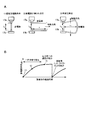
- FIG. 4A is a schematic diagram showing the state of the discharge path
- FIG. 4B is a graph showing the relationship between the extension amount of the discharge path and the elapsed time. It is a figure which shows the map data of the set time after discharge. It is a flowchart which shows the calculation operation of the inter-gap voltage in the inter-gap voltage calculation part which concerns on the 1st Embodiment example.
- FIG. 17A is a schematic view showing a state in which the discharge path is extended, and FIG. Is.
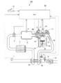
- FIG. 1 is a schematic configuration diagram showing a system configuration of the internal combustion engine of this example.
- the internal combustion engine 100 shown in FIG. 1 is an in-cylinder injection type internal combustion engine (direct injection engine) that directly injects fuel made of gasoline into the cylinder.
- the internal combustion engine 100 is a four-cycle engine that repeats four strokes of an intake stroke, a compression stroke, a combustion (expansion) stroke, and an exhaust stroke. Further, the internal combustion engine 100 is, for example, a multi-cylinder engine including four cylinders (cylinders).
- the number of cylinders of the internal combustion engine 100 is not limited to four, and may have six or eight or more cylinders. Further, the number of cycles of the internal combustion engine 100 is not limited to 4 cycles.
- the internal combustion engine 100 includes an air flow sensor 1, an electronically controlled throttle valve 2, an intake pressure sensor 3, a compressor 4a, an intercooler 7, and a cylinder 14.
- the air flow sensor 1, the electronically controlled throttle valve 2, the intake pressure sensor 3, the compressor 4a, and the intercooler 7 are arranged at positions up to the cylinder 14 in the intake pipe 6.
- the air flow sensor 1 measures the intake air amount and the intake air temperature.
- the electronically controlled throttle valve 2 is driven so as to be openable and closable by a drive motor (not shown). Then, the opening degree of the electronically controlled throttle valve 2 is adjusted based on the accelerator operation of the driver. As a result, the amount of air taken in is adjusted, and the pressure of the intake pipe 6 is adjusted.
- the intake pressure sensor 3 measures the pressure of the intake pipe 6.
- the compressor 4a is a supercharger that supercharges the intake air.
- a rotational force is transmitted to the compressor 4a by a turbine 4b described later.
- the intercooler 7 is arranged on the upstream side of the cylinder 14 to cool the intake air.
- the intake pipe 6 is provided with a partition wall 8 and a tumble control valve 8b for adjusting the flow velocity and flow of the gas flowing into the cylinder of the cylinder 14.
- the partition wall 8 divides the flow path in the vicinity of the cylinder 14 in the intake pipe 6 into two.
- the tumble control valve 8b is arranged on one side of the flow path divided into two by the partition wall 8. Then, in the state where the tumble control valve 8b is opened, the intake gas taken in from the flow paths on both sides divided by the partition wall 8 flows. Further, when the tumble control valve 8b is closed, the flow path on one side divided by the partition wall 8 is closed, and the intake gas flows through the flow path on the other side. As a result, the flow velocity of the intake gas flowing into the cylinder of the cylinder 14 increases. By controlling the closing degree of the tumble control valve 8b, the flow velocity of the gas flowing in the cylinder of the cylinder 14 is controlled.
- the internal combustion engine 100 is provided with an ignition device including an injector 13 for injecting fuel into the cylinder of the cylinder 14, an ignition coil 16 for supplying ignition energy, and a spark plug 17 for each cylinder 14.
- the ignition coil 16 generates a high voltage under the control of the internal combustion engine control device 20 and applies it to the spark plug 17. As a result, sparks are generated in the spark plug 17. Then, the spark generated in the spark plug 17 burns the air-fuel mixture in the cylinder and explodes.
- a voltage sensor (not shown) is attached to the ignition coil 16.
- the voltage sensor measures the primary side voltage or the secondary side voltage of the ignition coil 16. Then, the voltage information measured by the voltage sensor is sent to the internal combustion engine control device 20 which is an ECU (Engine Control Unit).
- ECU Engine Control Unit
- variable valve 5 adjusts the air-fuel mixture flowing into the cylinder of the cylinder 14 or the exhaust gas discharged from the cylinder. By adjusting the variable valve 5, the intake amount and the internal EGR amount of all the cylinders 14 are adjusted.
- a piston 14a is slidably arranged in the cylinder 14.
- the piston 14a compresses the mixture of fuel and gas that has flowed into the cylinder of the cylinder 14. Then, the piston 14a reciprocates in the cylinder 14 due to the combustion pressure generated in the cylinder. Further, a crank angle sensor 19 for detecting the position of the piston 14a is attached.
- the injector 13 is controlled by an internal combustion engine control device (ECU) 20, which will be described later, to inject fuel into the cylinder of the cylinder 14.
- ECU internal combustion engine control device
- a high-pressure fuel pump (not shown) is connected to the injector 13.
- the fuel whose pressure has been increased by the high-pressure fuel pump is supplied to the injector 13.
- a fuel pressure sensor for measuring the fuel injection pressure is provided in the fuel pipe connecting the injector 13 and the high-pressure fuel pump.
- the cylinder 14 is provided with a temperature sensor 18.
- the temperature sensor 18 measures the temperature of the cooling water circulating around the cylinder 14.
- an exhaust pipe 15 is connected to the exhaust port of the cylinder 14.
- the exhaust pipe 15 is provided with a turbine 4b, an electronically controlled waste gate valve 11, a three-way catalyst 10, and an air-fuel ratio sensor 9.
- the turbine 4b is rotated by the exhaust gas passing through the exhaust pipe 15 and transmits the rotational force to the compressor 4a.
- the electronically controlled waste gate valve 11 adjusts the exhaust flow path flowing through the turbine 4b.
- the three-way catalyst 10 purifies harmful substances contained in exhaust gas by an oxidation / reduction reaction. Further, the air-fuel ratio sensor 9 is arranged on the upstream side of the three-way catalyst 10. Then, the air-fuel ratio sensor 9 detects the air-fuel ratio of the exhaust gas passing through the exhaust pipe 15.
- the signals detected by each sensor such as the air flow sensor 1, the intake pressure sensor 3, and the voltage sensor are sent to the internal combustion engine control device 20. Further, the amount of depression of the accelerator pedal, that is, the signal detected by the accelerator opening sensor 12 that detects the accelerator opening is also sent to the internal combustion engine control device 20.
- the internal combustion engine control device 20 calculates the required torque based on the main signal of the accelerator opening sensor 12. That is, the accelerator opening degree sensor 12 is used as a required torque detection sensor for detecting the required torque for the internal combustion engine 100. Further, the internal combustion engine control device 20 calculates the rotation speed of the internal combustion engine 100 based on the output signal of the crank angle sensor (not shown). Then, the internal combustion engine control device 20 optimizes the main operating amounts of the internal combustion engine 100 such as air flow rate, fuel injection amount, ignition timing, and fuel pressure based on the operating state of the internal combustion engine 100 obtained from the outputs of various sensors. Calculate.
- the fuel injection amount calculated by the internal combustion engine control device 20 is converted into a valve opening pulse signal and output to the injector 13. Further, the ignition timing calculated by the internal combustion engine control device 20 is output to the spark plug 17 as an ignition signal. Further, the throttle opening calculated by the internal combustion engine control device 20 is output to the electronically controlled throttle valve 2 as a throttle drive signal.
- FIG. 2 is a block diagram showing the configuration of the internal combustion engine control device 20.
- the internal combustion engine control device 20 which is an ECU (Engine Control Unit) includes an input circuit 21, an input / output port 22, a RAM (Random Access Memory) 23c, and a ROM (Read Only Memory) 23b. , CPU (Central Processing Unit) 23a. Further, the internal combustion engine control device 20 has an ignition control unit 24 and a tumble control valve control unit 25.
- ECU Engine Control Unit
- RAM Random Access Memory
- ROM Read Only Memory
- CPU Central Processing Unit
- the suction flow rate from the air flow sensor 1, the intake pressure from the intake pressure sensor 3, and the coil primary voltage or secondary voltage from the voltage sensor are input to the input circuit 21. Further, information measured by various sensors such as a crank angle, a throttle opening degree and an exhaust air-fuel ratio is input to the input circuit 21.
- the input circuit 21 performs signal processing such as noise removal on the input signal and sends it to the input / output port 22.
- the value input to the input port of the input / output port 22 is stored in the RAM 23c.
- the ROM 23b stores a control program that describes the contents of various arithmetic processes executed by the CPU 23a, a MAP, a data table, and the like used for each process.
- the RAM 23c is provided with a storage area for storing the value input to the input port of the input / output port 22 and the value representing the operation amount of each actuator calculated according to the control program. Further, a value representing the operation amount of each actuator stored in the RAM 23c is sent to the output port of the input / output port 22.
- the ignition signal set in the output port of the input / output port 22 is sent to the ignition coil 16 via the ignition control unit 24.
- the ignition control unit 24 controls the energization timing and energization time of the ignition coil 16. Further, the ignition control unit 24 controls the discharge energy at the spark plug 17. Further, a drive signal indicating the opening / closing amount of the tumble control valve 8b set in the output port of the input / output port 22 is sent to the tumble control valve 8b via the tumble control valve control unit 25.
- the ignition control unit 24 and the tumble control valve control unit 25 are provided in the internal combustion engine control device 20 , but the present invention is not limited to this.
- a part of the ignition control unit 24 and the tumble control valve control unit 25, or all of the ignition control unit 24 and the tumble control valve control unit 25 may be mounted on a control device different from the internal combustion engine control device 20.
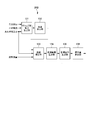
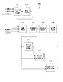
- FIG. 3 is a control block diagram showing an outline of discharge energy control in the ignition control unit.
- the ignition control unit 24 includes an inter-gap voltage calculation unit 31, a flow velocity calculation unit 32, a flow velocity range calculation unit 33, a target output calculation unit 34, and an operation amount calculation unit 35. ing.
- the inter-gap voltage calculation unit 31 and the center electrode 17a of the spark plug 17 are based on the secondary voltage applied to the ignition coil 16, the secondary current, and the in-cylinder pressure which is the pressure in the cylinder 4 of the cylinder 4 at the ignition timing.
- the voltage between the ground electrodes 17b (see FIG. 4) (hereinafter referred to as “gap”) is obtained.
- the inter-gap voltage calculation unit 31 obtains a voltage under a condition in which the length of the discharge path formed between the gaps differs depending on the voltage generated by the spark plug 17.
- the inter-gap voltage calculated by the inter-gap voltage calculation unit 31 is the inter-gap voltage and the post-discharge inter-gap voltage.
- the reference gap voltage is the gap voltage under the reference conditions.
- the reference condition is, for example, a condition in which the length of the discharge path immediately after discharge is equal to the distance between the gaps, that is, the shortest discharge condition.
- the shortest discharge condition will be described as a reference condition.
- the inter-gap voltage after discharge is the inter-gap voltage after the set time ti has elapsed after the start of discharge.
- the inter-gap voltage calculation unit 31 outputs the calculated reference inter-gap voltage and the post-discharge inter-gap voltage to the flow velocity calculation unit 32. The method of calculating the inter-gap voltage in the inter-gap voltage calculation unit 31 will be described later.
- the flow velocity calculation unit 32 calculates the flow velocity of the gas around the spark plug 17 based on the reference gap voltage calculated by the gap voltage calculation unit 31 and the post-discharge gap voltage. Then, the flow velocity calculation unit 32 outputs the calculated flow velocity calculation value around the spark plug 17 to the flow velocity range calculation unit 33. The method of calculating the flow velocity calculation value in the flow velocity calculation unit 32 will be described later.
- the flow velocity range calculation unit 33 holds the flow velocity calculation value (hereinafter referred to as the flow velocity) calculated by the flow velocity calculation unit 32 for the number of predetermined cycles N. Further, the flow velocity range calculation unit 33 calculates the maximum flow velocity value, the average flow velocity value, the flow velocity range, and the maximum value update flag.
- the maximum flow velocity value is the maximum value among the flow velocities for a predetermined number of cycles N held by the flow velocity range calculation unit 33.
- the flow velocity average value is the average value of the flow velocity for a predetermined number of cycles N held by the flow velocity range calculation unit 33.
- the flow velocity range is a value from the minimum value to the maximum value in the flow velocity value for a predetermined number of cycles N held by the flow velocity range calculation unit 33.
- the maximum value update flag is a flag indicating whether or not the maximum flow velocity value is updated. If there is an update, the maximum value update flag is set to positive (True). If there is no update, the maximum value update flag is set to False. Then, the maximum flow velocity value, the average flow velocity value, and the flow velocity range calculated by the flow velocity range calculation unit 33. The maximum value update flag is input to the target output calculation unit 34.
- the target output calculation unit 34 calculates the target value (target output) of the current and energy generated in the ignition coil 16 based on the maximum flow velocity value calculated by the flow velocity range calculation unit 33.
- the target output calculation unit 34 outputs the calculated target output to the operation amount calculation unit 35.
- the operation amount calculation unit 35 calculates the operation amount of the ignition coil 16 for achieving the target output.
- the operation amount calculated by the operation amount calculation unit 35 is, for example, the energization time of the ignition coil 16 on the primary side.
- FIG. 4A is a schematic diagram showing the state of the discharge path
- FIG. 4B is a graph showing the relationship between the extension amount of the discharge path and the elapsed time.
- FIG. 4A shows (1) the shortest discharge condition, (2) the condition in which the discharge path is extended, and (3) the condition in which re-discharge is imminent.
- the horizontal axis shows the elapsed time of discharge
- the vertical axis shows the amount of extension of the discharge path.
- the discharge path is transferred by the flow of gas around the spark plug 17.
- the transfer amount of the discharge path in the orthogonal direction is defined as the discharge path extension amount x [m].
- the length L SP [m] of the discharge path under the condition that the discharge path is extended as shown in FIG. 4A can be calculated by the following equation 1.
- the slope of the change in the discharge path extension amount x is constant in a predetermined time range after the discharge. Then, when the discharge path is further extended, re-discharge (restoring) occurs, and a new discharge path is formed. As a result, the discharge path extension amount x becomes small.
- the discharge path As shown in (3) the condition near re-discharging in FIG. 4A, the discharge path extends in a direction different from the orthogonal direction. This is because the flow of gas passing between the gaps changes direction in the opposite direction, so that the flow velocity includes components in the opposite direction. Therefore, under the condition (3) near re-discharge, the length of the discharge path cannot be estimated from Equation 1.
- the calculated discharge path extension amount (or discharge path length) is known (1).
- the flow velocity can be calculated from the shortest discharge condition, that is, the length of the discharge path immediately after discharge (the same value as the distance between gaps).
- Equation 1 Since it is difficult to use Equation 1 under the conditions (3) near re-discharge shown in FIGS. 4A and 4B, the set time ti should be set before (3) the state near re-discharge is reached. Is preferable.
- the setting time ti setting method include a setting method using a map showing the set time ti after discharge, which is constructed in advance by experiments and simulations, and a method of setting the set time ti based on the detected speed. ..
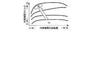
- FIG. 5 is a diagram showing map data of the set time ti after discharge.
- the vertical axis shows the torque of the internal combustion engine
- the horizontal axis shows the number of revolutions during the internal combustion period.
- the time until the state near re-discharging is affected by the flow velocity around the spark plug 17 and the followability to the flow of the discharge path.
- the followability to the flow of the discharge path is an index having a correlation with the magnitude of the relative velocity generated between the moving speed of the discharge path and the flow velocity around the spark plug 17.
- the followability at a ratio of two when the follow-up property is 1, it indicates that the flow velocity u air around the spark plug 17, the moving velocity u D of the discharge passage is consistent. Further, if the following property is less than 1, it indicates that the moving speed u D discharge path is small (slow) to the surrounding flow velocity u air of the spark plug 17. Further, the flow velocity air around the spark plug 17 increases as the rotational speed of the internal combustion engine 100 increases. Further, when the in-cylinder pressure of the cylinder 14 at the ignition timing is large, the followability becomes large. Therefore, the higher the rotation speed, the shorter the time to reach the state (3) near re-discharge. Further, the larger the in-cylinder pressure of the cylinder 14 at the ignition timing, the shorter the time required for (3) the state near re-discharging.
- the set time ti after discharge is set based on the torque and the rotation speed of the internal combustion engine 100, as shown in FIG. 5, the set time ti becomes smaller as the rotation speed is larger. Further, at the same rotation speed, the higher the torque, the smaller the set time ti. As a result, the set time ti can be set in consideration of (3) the time required for the state near re-discharging, which changes according to the operating conditions. Further, the flow velocity around the spark plug 17 can be calculated by this set time ti, and the calculation accuracy of the flow velocity can be improved.
- the flow velocity around the spark plug 17 is calculated by the flow velocity calculation method described later.
- the average flow velocity value u ave [m / s] is calculated from the flow velocity values for a predetermined number of cycles N.
- the average flow velocity value ave will be described later.
- the set time ti is calculated from the calculated average flow velocity value uave , the reference value x ref [m] of the discharge path extension amount, and the following equation 2.
- the reference value x ref of the discharge path extension amount is set in advance based on an experiment or a simulation. [Number 2]
- an appropriate set time ti can be set by reflecting individual variations and secular changes of the internal combustion engine 100. Can be set. In addition, the set time ti can be updated based on the latest information. As a result, it is possible to reduce the error in calculating the flow velocity caused by individual variation and secular change.
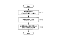
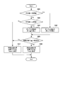
- FIG. 6 is a flowchart showing the calculation operation of the inter-gap voltage in the inter-gap voltage calculation unit 31.
- the inter-gap voltage calculation unit 31 calculates the inter-gap voltage in the shortest discharge path, that is, the reference inter-gap voltage V g0 [V] (step S11).
- the reference gap voltage Vg0 is expressed by Kim J. & Anderson RW (1995) Spark anemometry of bulk gas velocity at the plug gap of a firing engine (No.952459). It can be calculated using SAE Technical Paper). [Number 3]
- p is the cylinder pressure of the ignition timing [Pa]
- p 0 is the reference pressure (1 ⁇ 10 5) [Pa ]
- the I s is secondary current [A].
- the in-cylinder pressure p changes according to the operating conditions of the internal combustion engine 100.
- Reference gap voltage V g0 is calculated by the following Equation 4 by substituting the length gap distance L G discharge path of the discharge path length L sp shortest discharge path conditions in Equation 3. [Number 4]
- the cylinder pressure p and the secondary current I s of the ignition timing is required.
- the measured value of the in-cylinder pressure sensor can be used.
- the in-cylinder pressure p may be calculated from the following equation 5 based on the intake pressure detected by the intake pressure sensor 3, the in-cylinder volume at the intake valve closing timing, and the in-cylinder volume at the ignition timing. [Number 5]
- p int is the intake pressure [Pa]
- V ivc is cylinder volume of the intake valve closing timing [m 3].
- V adb is the cylinder internal volume [m 3 ] at the ignition timing
- ⁇ is the specific heat ratio. Under the stoichiometric mixed condition, the specific heat ratio can be set to about 1.33.
- the method of calculating the in-cylinder pressure p is not limited to the above-mentioned example.
- the in-cylinder pressure p may be set.
- the in-cylinder pressure p required for calculating the flow velocity can be calculated without using the in-cylinder pressure sensor.
- FIG. 7 is a diagram showing map data of the in-cylinder pressure p.
- the vertical axis shows the torque of the internal combustion engine
- the horizontal axis shows the number of revolutions during the internal combustion period.
- the in-cylinder pressure p at the ignition timing becomes high under the condition that the torque is large or the ignition timing is close to the top dead center.
- the torque is calculated based on the intake air amount and the throttle opening degree
- the rotation speed is calculated based on the measured value of the crank angle sensor 19.
- Secondary current I s to be included in the number 3 the secondary current in the set after the discharge time ti is used. Then, for example, a value measured by a current sensor installed on the secondary side of the ignition coil 16 can be applied to the secondary current.
- the setting method of the secondary current I s is not limited to the example using the current sensor.
- the relationship between the period for energizing the primary side of the ignition coil 16 (primary side energization time) and the secondary current at the set time ti after discharge is held in advance, and the secondary current Is may be set from this relationship. Good.
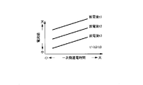
- FIG. 8 is a diagram showing the relationship between the primary side energization time and the secondary current at the set time ti after discharge.
- the set time ti after discharge is constant, the longer the primary side energization time, the larger the value of the secondary current at the set time ti after discharge.
- the set time ti time after discharge changes to t1, t2, t3 (t1 ⁇ t2 ⁇ t3), the longer the set time ti time after discharge, the secondary current at the set time ti after discharge. The value of becomes smaller.
- the primary side energization time is stored in a memory such as ROM 23b as an operation amount for the ignition coil 16 which is an ignition device.
- the formula for calculating the reference gap voltage Vg0 is not limited to the equations 3 and 4, and a formula for calculating the gap voltage constructed by the designer may be used.
- the gap voltage calculation unit 31 calculates the plug resistance R int [ ⁇ ] (step S12).
- the plug resistance R int corresponds to the sum of the resistance connected to the secondary side inside the ignition coil 16 and the resistance of the spark plug 17. Further, since the resistance of the spark plug 17 is larger than the resistance inside the ignition coil 16, the plug resistance R int can be obtained mainly by the resistance of the spark plug 17.
- the resistance value may be smaller than the set value of the internal resistance of the spark plug 17 or the measured value of a single unit.
- Such a decrease in which the resistance value becomes small can be represented by the following equation 6.
- R int, 0 is an installed value of the internal resistance of the spark plug 17, or a measured value [ ⁇ ] of a single unit.
- r int is the rate of change of internal resistance due to current [ ⁇ / A]
- Is and ref are the minimum values of the current value at which the internal resistance is smaller than the design value
- R int and lim are The lower limit of internal resistance [ ⁇ ]. Then, the rate of change of the internal resistance r int , the minimum value Is, ref of the current value at which the internal resistance becomes smaller than the installation value , and the lower limit value R int, lim of the internal resistance are measured in advance by experiments, for example, ROM23b or the like. Stored in.
- the value becomes negative when calculating the post-discharge gap voltage, which is the inter-gap voltage after the lapse of the set time ti after discharge, which will be described later. It can be prevented from becoming.
- the value of the plug resistance R int may be approximated to 0 [ ⁇ ]. In this way, by setting the internal resistance to 0, when calculating the post-discharge gap voltage using the change in the internal resistance due to the current, the flow velocity without forming the model of the internal resistance as shown in Equation 6 Can be calculated. In addition, it is possible to prevent the value of the flow velocity from being borne.
- the inter-gap voltage calculation unit 31 determines the inter-gap voltage in a state where the discharge path is extended, that is, the inter-gap voltage V after discharge, based on the measured value at the set time ti after discharge. g is calculated (step S13).
- the inter-gap voltage Vg after discharge is obtained by the following equation 7. [Number 7]
- V s is the secondary voltage [V].
- Secondary voltage V s is a voltage sensor connected to the ignition coil 16 may be used to the value measured.
- the secondary voltage V s may be calculated using the voltage measured on the primary side, the turns ratio of the primary side and the secondary side of the ignition coil 16.
- the secondary voltage V s is calculated from the following equation 8. [Number 8]
- the number of turns of the winding on the primary side is Ns
- the number of turns of the winding on the secondary side is Np.
- the inter-gap voltage calculation unit 31 When the calculation process of the discharge after the gap voltage V g is complete, operation of calculating the gap voltage at the gap voltage calculating unit 31 is completed. Then, the inter-gap voltage calculation unit 31 outputs the calculated reference inter-gap voltage V g0 and the post-discharge inter-gap voltage V g to the flow velocity calculation unit 32. In addition, the inter-gap voltage calculation unit 31 performs an inter-gap voltage calculation operation for each cycle.
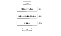
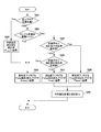
- FIG. 9 is a flowchart showing a flow velocity calculation operation in the flow velocity calculation unit 32.
- the flow rate calculation unit 32 calculates the reference gap voltage V g0 input from the gap voltage calculating unit 31 the ratio r v of the discharge after the gap voltage V g (step S21).
- the flow velocity calculating unit 32 by the following Equation 9 using the calculated voltage ratio r v, the discharge path length L sp in the setting of post-discharge time ti, calculates the ti.
- a and b are coefficients obtained from experiments.
- the discharge path length L sp calculated by the equation tens has an error in the measured value of the discharge path. This error is believed to be caused by errors due to sensor specifications, changes in internal resistance, sheath voltage and other uncertain reductions. Furthermore, as shown in Equation 10, the discharge path length L sp is the gap voltage V g, the ignition timing cylinder pressure p, is a function of the secondary current I s. On the other hand, the discharge path lengths L sp and ti calculated by Equation 9 are expressed by a linear equation with respect to the explanatory variable (voltage ratio). Furthermore, the number 9, the coefficient a, so b can accommodate a plurality of pressure and current conditions, and using the voltage ratio r v as explanatory variables.
- the discharge path length can be calculated accurately with a single relational expression under a plurality of pressure conditions and secondary current conditions.
- the discharge path lengths L sp, ti may be calculated from the equation tens without using the voltage ratio r v .
- the calculation formula in this case is the following number 11. [Number 11]
- the flow rate calculation unit 32 the discharge path length L sp after the calculated set time ti, is calculated around the flow velocity u p of the ignition plug 17 [m / s] from ti (step S23).
- Flow rate u p around the spark plug is calculated by the following equation (12). [Number 12]
- the operation of calculating the flow velocity u p in the flow velocity calculating unit 32 is completed. Further, the flow velocity calculating unit 32 outputs the calculated flow velocity u p to the flow velocity range calculating unit 33. Incidentally, the flow rate calculating unit 32 performs a calculation operation of the flow velocity u p per cycle. As described above, it is possible to calculate the measurement value of the coil voltage in the point, or by any other measurable signals and calculating values the flow velocity u p around the spark plug 17. Further, by limiting the measurement point to one point, the calculation load and the load of each sensor can be reduced.
- FIG. 10 is a flowchart showing an operation example of the flow velocity range calculation unit 33.
- the flow velocity range calculation unit 33 calculates the maximum value (um_h) before updating the flow velocity stored in the RAM 23c or the flow velocity range calculation unit 33 itself (step S31).
- the flow velocity range calculation unit 33 updates the flow velocity calculation value (flow velocity) of the Nth cycle (step S32).
- the flow velocity range calculation unit 33 deletes the data (flow velocity calculation value) of the oldest cycle among the plurality of stored flow velocity calculation values, and the flow velocity calculation unit 32 calculates the flow velocity in this cycle. Store the calculated value.
- the flow velocity range calculation unit 33 uses the flow velocity calculation value of the Nth cycle newly stored in the process of step S32 to obtain the maximum value, the average value, and the flow velocity range of the flow velocity calculation values for a predetermined number of cycles N. Is updated (step S34).
- step S34 determines whether or not the maximum value of the flow velocity calculation value before the update is equal to the maximum value updated in the process of step S34.
- the process of step S34 when the flow velocity range calculation unit 33 determines that the maximum value before update and the updated maximum value are equal (True determination in step S34), the process proceeds to the process of step S35 described later.
- step S34 when the flow velocity range calculation unit 33 determines that the maximum value before update and the updated maximum value are not equal (False determination in step S34), the process proceeds to the process of step S36 described later.
- the flow velocity range calculation unit 33 sets the maximum value update flag to False.
- the flow velocity range calculation unit 33 sets the maximum value update flag to True. As a result, the operation of the flow velocity range calculation unit 33 is completed. Further, the flow velocity range calculation unit 33 outputs the updated or calculated maximum value, average value, flow velocity range, and update flag information to the target output calculation unit 34.
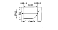
- Figure 11 is a diagram showing the relationship between a flow rate u p and the target output of around the spark plug 17.
- the target output is set large under the condition that the flow velocity around the spark plug 17 is large (maximum flow velocity value).
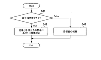
- FIG. 12 is a flowchart showing an operation example of the target output calculation unit 34.
- the target output calculation unit 34 determines the value of the maximum value update flag information input from the flow velocity range calculation unit 33 (step S41).
- the target output calculation unit 34 sets the target value based on the relationship between the flow velocity and the target output shown in FIG. (Step S42). Then, the target output calculation unit 34 outputs the set target value to the operation amount calculation unit 35.
- step S41 when the target output calculation unit 34 determines that the maximum value update flag is False, the target output calculation unit 34 maintains the currently set target value (step S43). As a result, the operation of the target output calculation unit 34 is completed.
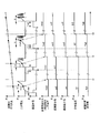
- FIG. 13 is a time chart showing a calculation operation of various information in the ignition control unit 24.
- the time chart shown in FIG. 13 shows the actual flow velocity, the secondary voltage, the energization time of the ignition coil 16, the secondary voltage value after the set time ti after discharge, the calculated flow velocity value, the maximum flow velocity value, and the target current (target). Value), the time history of the energization time set value is shown. At times t1, t2, and t3, the detection value is output and various calculation operations are performed.
- the secondary voltage Vm1 of the immediately preceding cycle is transmitted, and the flow velocity uc0 is calculated based on the secondary voltage Vm1.
- the maximum flow velocity value um of the N cycle, the target current It1, and the energization time set value Td1 are calculated.
- the flow velocity range calculation unit 33 since the flow velocity uc1 calculated using the secondary voltage Vm1 is smaller than the maximum value um before the update, the flow velocity range calculation unit 33 does not update the maximum flow velocity value. Therefore, the target current It1 and the energization time set value Td1 are not updated either.
- the flow velocity uc2 calculated based on the secondary voltage Vm2 is larger than the maximum flow velocity value um so far. Therefore, the maximum value of the flow velocity is updated from the flow velocity um to the flow velocity uc2. As a result, the target current is updated from It1 to It2, and the energization time set value is updated from Td1 to Td2. As a result, the energization time of the ignition coil 16 in the next cycle is set to Td2.
- the flow velocity uc3 calculated based on the secondary voltage Vm3 is larger than the conventional maximum flow velocity value u2, so the maximum flow velocity value is updated to the flow velocity uc3.
- the target current and the energization time set value are updated based on the maximum flow velocity value.
- the flow velocity at the ignition timing and the target value of the output to the ignition coil 16 can be set based on the detected value of the voltage of the ignition coil 16.
- the energization time of the ignition coil 16 can be controlled based on the calculated flow velocity, the generation of excessive energy can be suppressed, and the shortage of supply energy can be suppressed. Further, since the generation of excessive energy can be suppressed, the wear of the spark plug 17 can be prevented.
- FIG. 14 is a control block diagram showing an outline of discharge energy control in the ignition control unit according to the second embodiment.
- the ignition control unit 24B includes an inter-gap voltage calculation unit 131, a flow velocity calculation unit 132, a flow velocity correction unit 133, a flow velocity range calculation unit 134, a target output calculation unit 135, and an operation amount calculation. It is provided with a unit 136. That is, the ignition control unit 24B according to the second embodiment is provided with the flow velocity correction unit 133 in the ignition control unit 24 according to the first embodiment. Therefore, the flow velocity correction unit 133 will be described here.
- the air flow rate measured by the air flow sensor 1 is output to the flow velocity correction unit 133.
- the flow velocity correction unit 133 corrects the flow velocity calculation value calculated by the flow velocity calculation unit 132. Then, the flow velocity calculation value corrected by the flow velocity correction unit 133 is output to the flow velocity range calculation unit 134.
- FIG. 15 is a flowchart showing an operation example of the flow velocity correction unit 133.
- the flow velocity correction unit 133 calculates the in-cylinder gas density of the cylinder 14 (step S51).
- the flow velocity correction unit 133 includes an intake air flow rate Mair [kg] acquired from the airflow sensor 1, an exhaust air-fuel ratio AFR measured by the air-fuel ratio sensor 9, an in-cylinder volume V ADV [m 3 ] at the ignition timing, and an engine. based on the rotational speed N e, and calculates the in-cylinder gas density is a density of gas in the cylinder of the cylinder 14 ⁇ [kg / m 3] from following Expression 13. [Number 13]
- the flow velocity correction unit 133 corrects the flow velocity calculation value calculated by the flow velocity calculation unit 132 based on the in-cylinder gas density ⁇ calculated in step S51 and the input in-cylinder pressure (step S52). Then, the flow velocity correction unit 133 outputs the corrected flow velocity calculation value to the flow velocity range calculation unit 134. As a result, the operation of the flow velocity correction unit 133 is completed.
- step S52 the correction method performed in the process of step S52 will be described.
- the relationship between the flow velocity calculated by the flow velocity calculation unit 132 and the corrected flow velocity calculation value is obtained by an experiment carried out in advance, map data is created, and the map data is stored in a memory such as ROM 23b.
- the flow velocity correction value is calculated based on the created map data and the acquired flow velocity calculation value.
- the flow velocity correction unit 133 corrects the flow velocity calculation value based on the calculated flow velocity correction value.
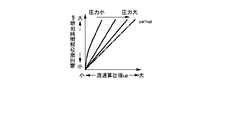
- FIG. 16 is map data showing the relationship between the flow velocity calculation value calculated by the flow velocity calculation unit 132 and the corrected flow velocity calculation value. As shown in FIG. 16, as compared to the uncorrected flow rate u p, it can be seen that the flow velocity u a corrected is large. Further, as the cylinder pressure is large, the difference in flow velocity u a corrected before correction of the flow velocity u p, it is seen that the smaller. By using the map data as shown in FIG. 16, the flow velocity can be corrected without adding a new sensor.
- the correction formula shown in Equation 14 is determined to reproduce the experimental results.
- the recommended value of the coefficient n is, for example, 0.5 to 1, but other values may be set.
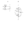
- FIGS. 17A and 17B are diagrams showing the relationship between the forces acting on the tip of the discharge path.
- FIG. 17A shows a state in which the discharge path is extended
- FIG. 17B is a view showing a tip portion extracted from the AA'line cross section of the discharge path shown in FIG. 17A.
- qM indicates Maxwell stress and r is the radius of the discharge path.
- Maxwell's stress is the stress that acts perpendicular to the surface and cross section of a conductor placed in an electric field. Then, when the entire tip of the discharge path is used as the inspection volume and the law of conservation of momentum in this inspection volume is taken into consideration, the following equations 15 and 16 are established.
- Equation 15 The first term on the left side of Equation 15 indicates the outflow amount of momentum from the control volume, and the second term on the left side indicates the inflow amount of momentum into the control volume.
- Equation 16 is an equation for applying Maxwell stress, and E is an electric field strength [V / m].
- Equation 16 is an equation for applying Maxwell stress, and E is an electric field strength [V / m].
- Equation 14 is a correction formula calculated by focusing on the tip of the discharge path and considering the stress of Maxwell acting on the tip of the discharge path.
- FIG. 18 is a control block diagram showing an outline of discharge energy control in the ignition control unit and the tumble control valve control unit according to the third embodiment.
- the ignition control unit 24C is connected to the tumble control valve control unit 177, the tumble control valve state determination unit 178, and the spark plug state determination unit 179. Further, the ignition control unit 24C is the same as the ignition control unit 24B according to the second embodiment, the gap voltage calculation unit 171, the flow velocity calculation unit 172, the flow velocity correction unit 173, and the flow velocity range calculation unit 174. A target output calculation unit 175 and an operation amount calculation unit 176 are provided. The flow velocity range calculation unit 174 outputs the calculated average flow velocity value to the tumble control valve control unit 177, the tumble control valve state determination unit 178, and the spark plug state determination unit 179.
- the tumble control valve control unit 177 determines the opening / closing degree of the tumble control valve 8b based on the average flow velocity value. Then, the tumble control valve control unit 177 outputs the tumble control valve operation amount to the tumble control valve 8b based on the determined opening / closing degree.
- the tumble control valve control unit 177 outputs an on-off valve operation amount change flag indicating whether or not the change amount of the target value of the opening / closing degree in the tumble control valve 8b is larger than a predetermined value.
- the on-off valve operation amount change flag is set to True when the target value change amount of the on-off degree is larger than a predetermined value. Then, when the target value change amount of the opening / closing degree does not reach the predetermined value, the on-off valve operating amount change flag is set to False. Further, the tumble control valve control unit 177 outputs the determined on-off valve operation amount change flag to the tumble control valve state determination unit 178.
- the tumble control valve state determination unit 178 causes a failure of the tumble control valve 8b based on the on-off valve operation amount change flag output from the tumble control valve control unit 177 and the flow velocity average value output from the flow velocity range calculation unit 174. Determine the presence or absence. Then, the tumble control valve state determination unit 178 determines the tumble control valve failure flag indicating the failure state of the tumble control valve 8b.
- the tumble control valve failure flag is set to True.
- the tumble control valve failure flag is set to False. Then, the tumble control valve state determination unit 178 outputs the determined tumble control valve failure flag to the spark plug state determination unit 179.
- the spark plug state determination unit 179 determines whether or not the spark plug 17 has a failure based on the tumble control valve failure flag output from the tumble control valve state determination unit 178 and the flow velocity average value output from the flow velocity range calculation unit 174. judge. Further, the spark plug state determination unit 179 determines a resistance reduction flag and a resistance increase flag indicating a failure state of the spark plug 17.
- the resistance reduction flag is a flag indicating the possibility of an abnormality in which the resistance value is lower than the design value. When the resistance reduction flag is set to True, it is indicated that there is a possibility that the resistance value of the spark plug 17 is lower than the design value.
- the resistance increase flag is a flag indicating the possibility of an abnormality in which the resistance value increases more than the design value.
- the resistance increase flag is set to True, it is shown that there is a possibility of abnormality that the resistance value of the spark plug 17 increases as well as the design value.
- spark plug state determination unit 179 sets the correction values R int and mod of the internal resistance of the spark plug 17 in Equation 6 to the design values R int and 0 .
- FIG. 19 is a flowchart showing an operation example of the tumble control valve control unit 177.
- the tumble control valve control unit 177 determines whether or not the flow velocity average value acquired from the flow velocity range calculation unit 174 is smaller than the target value (flow velocity target value) (step S61).
- the target value used in the process of step S61 is determined based on the rotation speed of the internal combustion engine 100 determined by the output of the crank angle sensor 19 and the map of the flow velocity target value. This map data is stored in a memory such as ROM 23b, for example.
- step S61 when the tumble control valve control unit 177 determines that the average flow velocity value is smaller than the target value (Yes determination in step S61), the tumble control valve control unit 177 further closes the tumble control valve 8b. Set the operation amount to control the direction. As a result, the amount of closing of the tumble control valve 8b increases (step S62).
- the amount of increase (change amount) of the closing amount is determined by, for example, defining in advance the difference between the target value and the mean flow velocity value and the relational expression proportional to the change amount. It can be set from the difference.
- step S62 when the process of step S62 is completed, the tumble control valve control unit 177 shifts to the process of step S65 described later.
- the tumble control valve control unit 177 controls the tumble control valve 8b so as to realize the target flow velocity condition.
- the flow velocity can be increased to realize a more stable and high-speed fuel state.
- the operation of the tumble control valve 8b deviates from the assumption due to aged deterioration or the variation due to individual differences can be eliminated, the desired performance can be realized.
- step S61 when the tumble control valve control unit 177 determines that the average flow velocity value is larger than the target value (No determination in step S61), whether or not the average flow velocity value is larger than the upper limit value. Determine (step S63).
- step S63 when the tumble control valve control unit 177 determines that the average flow velocity value is larger than the upper limit value (Yes determination in step S63), the operation amount is controlled so as to control the tumble control valve 8b in the direction of opening more. To set. As a result, the closing amount of the tumble control valve 8b is reduced (step S64).
- the decrease amount (change amount) of the closing amount is determined by, for example, defining in advance the difference between the upper limit value and the flow velocity average value and the relational expression proportional to the change amount. It can be set from the difference.
- the tumble control valve control unit 177 controls the tumble control valve 8b in the direction of opening the tumble control valve 8b more.
- step S65 the tumble control valve control unit 177 has a change in opening / closing degree (decrease in closing amount or increase in closing amount) set in the process in step S62 or the process in step S64, which is larger than a predetermined value. Judge whether or not.
- the predetermined value used in step S65 is set to a value that is expected to have a sufficient difference in the average flow velocity value.
- step S65 when the tumble control valve control unit 177 determines that the opening / closing degree change amount is larger than the predetermined value (Yes determination in step S65), the tumble control valve control unit 177 determines that the opening / closing valve operating amount.
- the change flag is set to True (step S66).
- step S63 when the tumble control valve control unit 177 determines that the average flow velocity value is smaller than the upper limit value (No determination in step S63), the process proceeds to the process of step S67. Further, in the process of step S65, when it is determined that the amount of change in the degree of opening / closing is smaller than the predetermined value (No determination in step S65), the tumble control valve control unit 177 shifts to the process of step S67.
- step S67 the tumble control valve control unit 177 sets the on-off valve operation amount change flag to False. Then, the tumble control valve control unit 177 outputs the on-off valve operation amount change flag set in step S66 or step S67 to the tumble control valve state determination unit 178. As a result, the operation of the tumble control valve control unit 177 is completed.
- FIG. 20 is a flowchart showing the operation of the tumble control valve state determination unit 178.
- the tumble control valve state determination unit 178 determines the state of the on-off valve operation amount change flag output from the tumble control valve control unit 177 (step S71).
- the tumble control valve state determination unit 178 determines that the on-off valve operation amount change flag is True in the process of step S71, the process proceeds to the process of step S72. Further, in the process of step S71, when the tumble control valve state determination unit 178 determines that the on-off valve operation amount change flag is False, the process proceeds to the process of step S75.
- the tumble control valve state determination unit 178 holds the average flow velocity value before operating the tumble control valve 8b as a comparison value.
- This comparison value is a value for comparison for determining whether or not there is a difference in the flow velocity average value before and after the operation of the tumble control valve 8b.
- the tumble control valve state determination unit 178 sets the value of the tacounter Nth to "0" (step S73).
- the counter Nth counts the number of series of operations in the tumble control valve state determination unit 178 after the on-off valve operation amount changes significantly, that is, the on-off valve operation amount change flag is set to True.
- the tumble control valve state determination unit 178 sets the tumble control valve failure flag to False (step S74). Then, the tumble control valve state determination unit 178 outputs the set tumble control valve failure flag to the spark plug state determination unit 179. As a result, one operation of the tumble control valve state determination unit 178 is completed.
- step S75 1 is incremented to the counter Nth.
- the number of times a series of operations in the tumble control valve state determination unit 178 is performed is counted.
- the tumble control valve state determination unit 178 determines whether or not the value of the counter Nth is the same as the value of the number of data N held by the flow velocity range calculation unit 174, that is, the value of the predetermined number of cycles N (step). S76). In the process of step S76, when the value of the counter Nth and the value of the number of data N are equal, all the flow velocity information held in the flow velocity range calculation unit 174 is after the opening / closing operation of the tumble control valve 8b is performed. Flow velocity information.
- step S76 when the tumble control valve state determination unit 178 determines that the value of the counter Nth and the value of the number of data N are not equal (False determination in step S76), the tumble control valve state determination unit 178 determines. Complete the operation.
- step S76 when the tumble control valve state determination unit 178 determines that the value of the counter Nth and the value of the number of data N are equal (True determination in step S76), the flow velocity comparison value (uh) is determined. It is determined whether or not the difference from the average flow velocity value (auve) is smaller than the reference value (step S77).
- the flow velocity comparison value is a value held in the process of step S72 in the process operation prior to the current process operation. Further, in the process of step S77, it is determined whether or not the flow velocity has changed.
- step S77 When it is determined in the process of step S77 that the difference between the flow velocity comparison value and the flow velocity average value is smaller than the reference value (True determination in step S77), the tumble control valve state determination unit 178 sets the tumble control valve failure flag to True. Set (step S78). That is, since the flow velocity does not change even though the tumble control valve 8b is operated, the tumble control valve state determination unit 178 determines that the tumble control valve 8b may have failed. Then, the tumble control valve state determination unit 178 outputs the tumble control valve failure flag to the spark plug state determination unit 179.
- step S77 when it is determined that the difference between the flow velocity comparison value and the flow velocity average value is larger than the reference value (False determination in step S77), the tumble control valve state determination unit 178 sets the tumble control valve failure flag. Set to False (step S79). That is, it shows that the flow velocity changes according to the operation of the tumble control valve 8b, and it is assumed that the tumble control valve 8b is performing a desired operation. As a result, the tumble control valve state determination unit 178 determines that the tumble control valve 8b is normal. Further, the tumble control valve state determination unit 178 outputs a tumble control valve failure flag to the spark plug state determination unit 179. As a result, the operation of the tumble control valve state determination unit 178 is completed.
- the tumble control valve state determination unit 178 compares the average value of the flow velocities before and after the opening / closing degree of the tumble control valve 8b changes more than a predetermined value, and determines the presence or absence of the change in the flow velocity. .. Then, based on this result, it can be determined whether or not the tumble control valve 8b is performing a desired operation, and a failure of the tumble control valve 8b can be determined.
- FIG. 21 is a flowchart showing the operation of the spark plug state determination unit 179.
- the spark plug state determination unit 179 determines whether or not the spark plug 17 is replaced (step S81).
- step S81 when the spark plug state determination unit 179 determines that the spark plug 17 has been replaced (True in step S81), the design of the internal resistance of the spark plug 17 whose correction values Rint and mod are shown in Equation 6.
- the value R int is set to 0 (step S82).
- step S81 when the spark plug state determination unit 179 determines that the spark plug 17 has not been replaced (False in step S81), the tumble control valve failure flag is determined (step S83).
- step S83 when the spark plug state determination unit 179 determines that the tumble control valve failure flag is False (False determination in step S83), the process proceeds to the process of step S84.
- step S83 when the spark plug state determination unit 179 determines that the tumble control valve failure flag is True (True determination in step S83), the process proceeds to the process of step S86.
- the spark plug state determination unit 179 determines whether or not the flow velocity average value calculated by the flow velocity range calculation unit 174 is smaller than the resistance reduction determination reference value. This makes it possible to determine whether or not an abnormality has occurred due to a decrease in the internal resistance of the spark plug 17.
- the reference value for determining the decrease in resistance is a flow velocity reference value for determining an abnormality due to a decrease in the internal resistance of the spark plug 17.
- the resistance decrease determination is made. Reference value is used. Further, the reference value for determining the resistance decrease is obtained by, for example, an experiment or a simulation conducted in advance.
- step S84 when the spark plug state determination unit 179 determines that the average flow velocity value is equal to or higher than the resistance reduction determination reference value (False determination in step S84), the process proceeds to the process of step S85. Further, in the process of step S84, when the spark plug state determination unit 179 determines that the average flow velocity value is smaller than the reference value for determining the resistance decrease (True determination in step S84), the process proceeds to the process of step S88.
- the state of the flow velocity can be determined from the relationship between the average value of the predetermined number of cycles N of the flow velocity calculation values calculated by the flow velocity calculation unit 172 and the reference value (reference value for determining resistance decrease). Further, based on the state of the average flow velocity value, it is possible to determine whether or not an abnormality has occurred due to a decrease in the internal resistance of the spark plug 17.
- the spark plug state determination unit 179 determines whether or not the average flow velocity value calculated by the flow velocity range calculation unit 174 is larger than the reference value for determining resistance increase. This makes it possible to determine whether or not an abnormality has occurred due to an increase in the internal resistance of the spark plug 17, that is, an increase in the internal resistance from the design value.
- the reference value for determining the increase in resistance is a flow velocity reference value for determining an abnormality due to an increase in the internal resistance of the spark plug 17.
- the resistance is increased.
- the reference value for determination of conversion is used. Further, the reference value for determining the resistance increase is obtained by, for example, an experiment or a simulation conducted in advance.
- step S85 when the spark plug state determination unit 179 determines that the average flow velocity value is equal to or less than the reference value for determining resistance increase (False determination in step S85), the process proceeds to the process of step S86. Further, in the process of step S85, when the ignition plug state determination unit 179 determines that the average flow velocity value is larger than the reference value for determining the resistance decrease (True determination in step S85), the process proceeds to the process of step S87.
- step S86 the spark plug state determination unit 179 sets the resistance lowering flag to False and the resistance increasing flag to False. That is, the spark plug state determination unit 179 determines that no abnormality has occurred in the spark plug 17. Then, the operation of the spark plug state determination unit 179 is completed.
- step S87 the spark plug state determination unit 179 sets the resistance reduction flag to False and the resistance increase flag to True. Then, the spark plug state determination unit 179 shifts to the process of step S89.
- step S88 the spark plug state determination unit 179 sets the resistance reduction flag to True and the resistance increase flag to False. Then, the spark plug state determination unit 179 shifts to the process of step S89.
- the spark plug state determination unit 179 sets the correction values R int and mod for correcting the design values R int and 0 of the internal resistance of the spark plug 17 used in the calculation formula (Equation 6) of the internal resistance. calculate.
- the correction values R int and mod are, for example, the average flow velocity uave_asm , the average flow velocity value u ave , and the design values R int, 0 , and the equation 9 of the internal resistance assumed under the current operating conditions and the tumble control valve operating amount conditions. It is calculated by the following equation 19 using the coefficient a. [Number 19]
- the average flow velocity uave_asm assumed under the current operating conditions and the conditions of the tumble control valve operating amount is calculated by an experiment carried out in advance and stored in a memory such as ROM 23b.
- a memory such as ROM 23b.
- the resistance reduction flag is set to True, when an abnormality due to a decrease in the internal resistance occurs is smaller than the average flow velocity u Ave_asm flow velocity average value u ave is assumed. Therefore, the correction values R int and mod calculated by the equation 19 are smaller than the design values R int and 0 .
- the resistance high flag is set to True, when an abnormality due Koka internal resistance occurs is greater than the average flow velocity u Ave_asm flow velocity average value u ave is assumed. Therefore, the correction values R int and mod calculated by the equation 19 are larger than the design values R int and 0 .
- the spark plug state determination unit 179 outputs the calculated correction values R int and mod to the inter-gap voltage calculation unit 171.
- the inter-gap voltage calculation unit 171 uses the correction values R int and mod calculated by the spark plug state determination unit 179 instead of the design values R int and 0 of the internal resistance of the spark plug 17, and the plug resistance R int. Is calculated. As a result, even if the internal resistance of the spark plug 17 is damaged, the flow velocity calculation accuracy can be ensured.
- the spark plug state determination unit 179 By determining the state of the internal resistance of the spark plug 17 by the spark plug state determination unit 179, it is possible to determine whether or not an abnormality has occurred in the internal resistance of the spark plug 17.
- Air fuel ratio sensor 10 ... Three-way catalyst, 12 ... Accelerator opening sensor, 13 ... Injector, 14 ... Cylinder, 14a ... Piston, 15 ... Exhaust pipe, 16 ... Ignition coil, 17 ... Spark plug, 17a ... Center Electrodes, 17b ... ground electrode, 18 ... temperature sensor, 19 ... crank angle sensor, 20 ... internal combustion engine control device, 21 ... input circuit, 22 ...
Landscapes
- Engineering & Computer Science (AREA)
- Chemical & Material Sciences (AREA)
- Combustion & Propulsion (AREA)
- Mechanical Engineering (AREA)
- General Engineering & Computer Science (AREA)
- Signal Processing (AREA)
- Ignition Installations For Internal Combustion Engines (AREA)
- Electrical Control Of Ignition Timing (AREA)
- Combustion Methods Of Internal-Combustion Engines (AREA)
- Combined Controls Of Internal Combustion Engines (AREA)
Abstract
計測負荷を低減し、かつ点火プラグ周りの流速を算出することができる内燃機関制御装置を提供する。 内燃機関制御装置は、ギャップ間電圧算出部31と、流速算出部32と、を備えている。ギャップ間電圧算出部31は、二次電流及び筒内圧力に基づいて、基準条件での基準ギャップ間電圧を算出する。流速算出部は、基準ギャップ間電圧に基づいて、点火プラグの周囲のガスの流速を算出する。
Description
本発明は、内燃機関制御装置に関するものである。
自動車の燃費性能を向上させるためには、内燃機関の燃料消費量を低減することが重要である。燃料消費量を低減させる技術としては、ポンプ損失や冷却損失の低減手段として、燃料と空気の比率を量論混合比(理想混合比)に比べて希釈して燃焼させる希釈燃焼が知られている。また、他の技術としては、燃焼ガスの一部を吸気側に戻して燃料と空気の混合気を希釈するEGR(Exhaust Gas Recirculation)ガスを活用した燃焼方式がある。
また、燃料消費量を低減するためには、運転条件に応じて適切な混合気の希釈度を設定する必要がある。さらに、希釈度の大きな条件、すなわち混合気が希薄な状態での失火を避けて燃焼を実現するためには、燃料の相対的な濃度が小さくなっているため、火花点火時に点火プラグから気筒内の混合気に供給する放電エネルギ量を増加させる必要がある。
また、希釈度の大きな条件で安定的な燃焼を実現するためには、内燃機関の気筒内の混合気の乱流強度や、流速を増加させる必要がある。しかしながら、乱流強度や流速が大きくなると、点火プラグでの放電の吹き消え等の現象により失火発生の可能性が生じる。そのため、火花点火時に点火プラグから気筒内の混合気に供給する放電エネルギ量も増加させる必要がある。
そして、流速の増加による放電の吹き消えを防ぐためには、点火プラグの周囲の流速を検出し、放電エネルギや放電電流を制御することが有効である。点火プラグの周囲の流速を検出する技術としては。例えば、特許文献1に記載されているようなものがある。
特許文献1には、2次コイルにより生じた電圧である2次電圧を検出する2次電圧検出部と、放電期間中の2次電圧の最小値を算出する2次電圧最小値算出部を備えた技術が記載されている。そして、特許文献1に記載された技術では、2次電圧、及び2次電圧の最小値に基づいて、放電プラズマの長さを算出し、放電プラズマの長さの時間変化とクーロン力に基づいて筒内流動速度を算出している。
しかしながら、特許文献1に記載された技術では、点火プラグの周囲の流速を算出するために、コイルの二次電圧を放電後に複数回計測していた。そのため、時々刻々と変化する流速を算出するためには、特許文献1に記載された技術では、多数の電圧計測処理が必要となり、計測負荷が増大する、という問題を有していた。
本目的は、上記の問題点を考慮し、計測負荷を低減し、かつ点火プラグ周りの流速を算出することができる内燃機関制御装置を提供することにある。
上記課題を解決し、目的を達成するため、内燃機関制御装置は、シリンダの筒内に配置された点火プラグと、点火プラグに電圧を印加する点火コイルとを備えた内燃機関を制御する内燃機関制御装置である。内燃機関制御装置は、ギャップ間電圧算出部と、流速算出部と、を備えている。ギャップ間電圧算出部は、点火コイルの二次側に発生する二次電流及びシリンダの筒内の圧力である筒内圧力に基づいて、基準条件での点火プラグのギャップ間の電圧である基準ギャップ間電圧を算出する。流速算出部は、基準ギャップ間電圧に基づいて、点火プラグの周囲のガスの流速を算出する。
上記構成の内燃機関制御装置によれば、計測負荷を低減し、かつ点火プラグ周りの流速を算出することができる。
1.実施の形態例
以下、実施の形態例(以下、「本例」という)にかかる内燃機関制御装置について、図1~図21を参照して説明する。なお、各図において共通の部材には、同一の符号を付している。
以下、実施の形態例(以下、「本例」という)にかかる内燃機関制御装置について、図1~図21を参照して説明する。なお、各図において共通の部材には、同一の符号を付している。
1-1.内燃機関の構成例
まず、内燃機関の構成例について説明する。
図1は、本例の内燃機関のシステム構成を示す概略構成図である。
まず、内燃機関の構成例について説明する。
図1は、本例の内燃機関のシステム構成を示す概略構成図である。
図1に示す内燃機関100は、ガソリンからなる燃料を筒内に直接噴射する筒内噴射型の内燃機関(直噴エンジン)である。内燃機関100は、吸入行程、圧縮行程、燃焼(膨張)行程、排気行程の4行程を繰り返す4サイクルエンジンである。さらに、内燃機関100は、例えば、4つの気筒(シリンダ)を備えた多気筒エンジンである。なお、内燃機関100が有する気筒の数は、4つに限定されるものではなく、6つ又は8つ以上の気筒を有していてもよい。また、内燃機関100のサイクル数は、4サイクルに限定されるものではない、
図1に示すように、内燃機関100は、エアフローセンサ1と、電子制御スロットル弁2と、吸気圧センサ3と、コンプレッサ4aと、インタークーラ7と、シリンダ14とを備えている。エアフローセンサ1、電子制御スロットル弁2、吸気圧センサ3、コンプレッサ4a、インタークーラ7は、吸気管6におけるシリンダ14までの位置に配置されている。
また、エアフローセンサ1は、吸入空気量と、吸気温度を計測する。電子制御スロットル弁2は、不図示の駆動モータにより開閉可能に駆動する。そして、運転者のアクセル操作に基づいて、電子制御スロットル弁2の開度が調整される。これにより、吸気される空気量を調整し、吸気管6の圧力を調整する。吸気圧センサ3は、吸気管6の圧力を計測する。
コンプレッサ4aは、吸気を過給する過給機である。このコンプレッサ4aは、後述するタービン4bにより回転力が伝達される。インタークーラ7は、シリンダ14の上流側に配置され、吸気を冷却する。
吸気管6には、シリンダ14の筒内へ流入するガスの流速や流れを調整する隔壁8及びタンブル制御弁8bが設けられている。隔壁8は、吸気管6におけるシリンダ14の近傍の流路を2つい分割している。タンブル制御弁8bは、隔壁8により2つに分割された流路の片側に配置されている。そして、タンブル制御弁8bを開けた状態では、隔壁8により分割された両側の流路を吸気された吸気ガスが流れる。また、タンブル制御弁8bを閉じた状態では、隔壁8により分割された片側の流路が閉塞し、残りの片側の流路を吸気ガスが流れる。これにより、シリンダ14の筒内に流れ込む吸気ガスの流速が増加する。このタンブル制御弁8bの閉じ具合を制御することで、シリンダ14の筒内を流れるガスの流速が制御される。
また、内燃機関100は、シリンダ14の筒内に燃料を噴射するインジェクタ13と、点火エネルギを供給する点火コイル16及び点火プラグ17からなる点火装置がシリンダ14ごとに設けられている。点火コイル16は、内燃機関制御装置20の制御の下、高電圧を生成し、点火プラグ17に印加する。これにより、点火プラグ17に火花が発生する。そして、点火プラグ17に発生した火花により、筒内の混合気が燃焼し、爆発する。
また、点火コイル16には、不図示の電圧センサが取り付けられている。電圧センサは、点火コイル16の一次側電圧又は二次側電圧を計測する。そして、電圧センサが計測した電圧情報は、ECU(Engine Control Unit)である内燃機関制御装置20に送られる。
また、シリンダ14のシリンダヘッドには、可変バルブ5が設けられている。可変バルブ5は、シリンダ14の筒内に流入する混合気、または筒内から排出する排気ガスを調整する。可変バルブ5を調整することにより、全シリンダ14の吸気量及び内部EGR量が調整される。
さらに、シリンダ14の筒内には、ピストン14aが摺動可能に配置されている。ピストン14aは、シリンダ14の筒内に流入した燃料とガスの混合気を圧縮する。そして、ピストン14aは、筒内に生じた燃焼圧力によりシリンダ14の筒内を往復運動する。また、ピストン14aの位置を検出するためのクランク角度センサ19が取り付けられている。
インジェクタ13は、後述する内燃機関制御装置(ECU)20に制御されて、シリンダ14の筒内に燃料を噴射する。これにより、シリンダ14の筒内には、空気の燃料が混合された混合気が生成される。また、インジェクタ13には、不図示の高圧燃料ポンプが接続されている。高圧燃料ポンプにより圧力が高められた燃料がインジェクタ13に供給される。さらに、インジェクタ13と高圧燃料ポンプとを接続する燃料配管には、燃料噴射圧力を計測するための燃料圧力センサが設けられている。
また、シリンダ14には、温度センサ18が設けられている。温度センサ18は、シリンダ14を巡る冷却水の温度を計測する。
さらに、シリンダ14の排気ポートには、排気管15が接続されている。排気管15には、タービン4b、電子制御ウエイストゲート弁11、三元触媒10、空燃比センサ9が設けられている。タービン4bは、排気管15を通過する排気ガスにより回転し、コンプレッサ4aに回転力を伝える。電子制御ウエイストゲート弁11は、タービン4bに流れる排気流路を調整する。
三元触媒10は、酸化・還元反応により排気ガスに含まれる有害物質を浄化する。また、空燃比センサ9は、三元触媒10の上流側に配置されている。そして、空燃比センサ9は、排気管15を通る排気ガスの空燃比を検出する。
また、エアフローセンサ1、吸気圧センサ3、電圧センサ等の各センサが検出した信号は、内燃機関制御装置20に送られる。また、アクセルペダルの踏み込み量、すなわち、アクセル開度を検出するアクセル開度センサ12が検出した信号も内燃機関制御装置20に送られる。
内燃機関制御装置20は、アクセル開度センサ12の主力信号に基づいて、要求トルクを演算する。すなわち、アクセル開度センサ12は、内燃機関100への要求トルクを検出する要求トルク検出センサとして用いられる。また、内燃機関制御装置20は、不図示のクランク角度センサの出力信号に基づいて、内燃機関100の回転速度を演算する。そして、内燃機関制御装置20は、各種センサの出力から得られる内燃機関100の運転状態に基づき、空気流量、燃料噴射量、点火時期、燃料圧力等の内燃機関100の主要な作動量を最適に演算する。
内燃機関制御装置20により演算した燃料噴射量は、開弁パルス信号に変換され、インジェクタ13に出力される。また、内燃機関制御装置20により演算された点火時期は、点火信号として点火プラグ17に出力される。さらに、内燃機関制御装置20により演算されたスロットル開度は、スロットル駆動信号として電子制御スロットル弁2に出力される。
1-2.内燃機関制御装置20の構成例
次に、図2を参照して内燃機関制御装置20の構成例について説明する。
図2は、内燃機関制御装置20の構成を示すブロック図である。
次に、図2を参照して内燃機関制御装置20の構成例について説明する。
図2は、内燃機関制御装置20の構成を示すブロック図である。
図2に示すように、ECU(Engine Control Unit)である内燃機関制御装置20は、入力回路21と、入出力ポート22と、RAM(Random Access Memory)23cと、ROM(Read Only Memory)23bと、CPU(Central Processing Unit)23aを有する。また、内燃機関制御装置20は、点火制御部24と、タンブル制御弁制御部25を有している。
入力回路21には、エアフローセンサ1からの吸入流量、吸気圧センサ3からの吸気圧、電圧センサからのコイル一次電圧又は二次電圧が入力される。また、入力回路21には、クランク角度、スロットル開度や排気空燃比等の各種センサが計測した情報が入力される。
入力回路21は、入力された信号に対してノイズ除去等の信号処理を行って、入出力ポート22へ送る。入出力ポート22の入力ポートに入力された値はRAM23cに格納される。
ROM23bには、CPU23aにより実行される各種演算処理の内容を記述した制御プログラムや、各処理に用いられるMAPやデータテーブル等が記憶されている。RAM23cには、入出力ポート22の入力ポートに入力された値や、制御プログラムに従って演算された各アクチュエータの操作量を表す値を格納する格納領域が設けられている。また、RAM23cに格納された各アクチュエータの操作量を表す値は、入出力ポート22の出力ポートに送られる。
入出力ポート22の出力ポートにセットされた点火信号は、点火制御部24を経て、点火コイル16に送られる。点火制御部24は、点火コイル16への通電時期や通電時間を制御する。さらに、点火制御部24は、点火プラグ17での放電エネルギ制御を行う。また、入出力ポート22の出力ポートにセットされたタンブル制御弁8bの開閉量を示す駆動信号は、タンブル制御弁制御部25を経て、タンブル制御弁8bに送られる。
なお、本例では、内燃機関制御装置20に点火制御部24及びタンブル制御弁制御部25を設けた例を説明したが、これに限定されるものではない。例えば、点火制御部24やタンブル制御弁制御部25の一部、あるいは点火制御部24やタンブル制御弁制御部25の全てを内燃機関制御装置20とは異なる制御装置に実装してもよい。
2.点火制御部の構成例2-1.第1の実施の形態例
次に、点火制御部の第1の実施の形態例について図3から図12を参照して説明する。
図3は、点火制御部における放電エネルギ制御の概要を示す制御ブロック図である。
次に、点火制御部の第1の実施の形態例について図3から図12を参照して説明する。
図3は、点火制御部における放電エネルギ制御の概要を示す制御ブロック図である。
図3に示すように、点火制御部24は、ギャップ間電圧算出部31と、流速算出部32と、流速範囲算出部33と、目標出力算出部34と、操作量算出部35とを有している。
ギャップ間電圧算出部31は、点火コイル16に印加される二次電圧、二次電流及び点火時期のシリンダ4の筒内の圧力である筒内圧力に基づいて、点火プラグ17の中心電極17aと接地電極17b(図4参照)の間(以下、ギャップ間という)の電圧を求める。
ギャップ間電圧算出部31は、点火コイル16に印加される二次電圧、二次電流及び点火時期のシリンダ4の筒内の圧力である筒内圧力に基づいて、点火プラグ17の中心電極17aと接地電極17b(図4参照)の間(以下、ギャップ間という)の電圧を求める。
ギャップ間電圧算出部31は、点火プラグ17で発生させた電圧によりギャップ間に形成される放電路の長さが異なる条件の電圧を求める。ギャップ間電圧算出部31が算出するギャップ間電圧は、基準ギャップ間電圧と、放電後ギャップ間電圧である。基準ギャップ間電圧は、基準条件でのギャップ間電圧である。基準条件としては、例えば、放電直後の放電路の長さがギャップ間の距離と等しい条件、すなわち最短放電条件である。以下、基準条件として最短放電条件を用いて説明する。
放電後ギャップ間電圧は、放電を開始した後に設定時間tiが経過した後のギャップ間電圧である。ギャップ間電圧算出部31は、算出した基準ギャップ間電圧と、放電後ギャップ間電圧を流速算出部32に出力する。なお、ギャップ間電圧算出部31におけるギャップ間電圧の算出方法については、後述する。
流速算出部32は、ギャップ間電圧算出部31が算出した基準ギャップ間電圧と、放電後ギャップ間電圧に基づいて、点火プラグ17の周囲のガスの流速を算出する。そして、流速算出部32は、算出した点火プラグ17の周囲の流速算出値を流速範囲算出部33に出力する。なお、流速算出部32における流速算出値の算出方法については、後述する。
流速範囲算出部33は、所定のサイクル数Nの数だけ、流速算出部32が算出した流速算出値(以下、流速という。)を保持する。また、流速範囲算出部33は、流速最大値、流速平均値、流速範囲、及び最大値更新フラグを算出する。流速最大値は、流速範囲算出部33が保持した所定サイクル数N分の流速のうちの最大値である。また、流速平均値は、流速範囲算出部33が保持した所定サイクル数N分の流速の平均値である。
さらに、流速範囲は、流速範囲算出部33が保持した所定サイクル数N分の流速値における最小値から最大値までの値である。また、最大値更新フラグは、流速最大値の更新の有無を示すフラグである。更新有りの場合には、最大値更新フラグは、正(True)に設定される。また、更新無しの場合には、最大値更新フラグは、誤(False)に設定される。そして、流速範囲算出部33が算出した、流速最大値、流速平均値、流速範囲。
最大値更新フラグは、目標出力算出部34に入力される。
最大値更新フラグは、目標出力算出部34に入力される。
目標出力算出部34は、流速範囲算出部33で算出された、流速最大値に基づいて点火コイル16で発生する電流やエネルギの目標値(目標出力)を算出する。目標出力算出部34は、算出した目標出力を操作量算出部35に出力する。
操作量算出部35は、目標出力を実現するための点火コイル16の操作量を算出する。
操作量算出部35が算出する操作量としては、例えば、点火コイル16の一次側への通電時間である。
操作量算出部35が算出する操作量としては、例えば、点火コイル16の一次側への通電時間である。
[放電路の状態の時間変化及び電極間距離]
次に、図4A及び図4Bを参照して放電路の状態の時間変化及び電極間距離について説明する。
図4Aは、放電路の状態を示す模式図、図4Bは放電路の伸長量と経過時間との関係を示すグラフである。図4Aには、(1)最短放電条件、(2)放電路が伸びた条件、(3)再放電間近の条件について示す。また、図4Bは、横軸に放電の経過時間、縦軸に放電路の伸長量を示している。
次に、図4A及び図4Bを参照して放電路の状態の時間変化及び電極間距離について説明する。
図4Aは、放電路の状態を示す模式図、図4Bは放電路の伸長量と経過時間との関係を示すグラフである。図4Aには、(1)最短放電条件、(2)放電路が伸びた条件、(3)再放電間近の条件について示す。また、図4Bは、横軸に放電の経過時間、縦軸に放電路の伸長量を示している。
図4Aに示すように、(1)最短放電条件は、放電路の長さは、点火プラグ17の中心電極17aと接地電極17bの距離(いわゆるギャップ間距離)LG[m]と同じ長さとなる。
また、放電を開始した後、点火プラグ17の周囲のガスの流れにより、放電路が移送される。ここで、中心電極17aと接地電極17bが対向する対向方向と直交する直交方向にガスが流れていると想定し、直交方向への放電路の移送量を放電路伸長量x[m]と定義する。そして、放電後から有る程度の時間範囲では、放電路の変形は、直交方向のみに生じると近似することができる。そのため、図4Aに示す(2)放電路が伸びた条件での放電路の長さLSP[m]は、下記数1により算出することができる。
[数1]

[数1]
また、図4Bに示すように、放電後から所定の時間範囲では、放電路伸長量xの変化の傾きが一定である。そして、さらに放電路が伸びると再放電(リストライク)が発生し、放電路が新たに形成される。その結果、放電路伸長量xが小さくなる。図4Aにおける(3)再放電間近の条件に示すように、放電路は、直交方向とは異なる方向にも伸長する。
これは、ギャップ間を通過したガスの流れが対向方向に向きを変えることで、流速が対向方向の成分も含むためである。そのため、(3)再放電間近の条件では、放電路の長さを数1から推定することができない。
これは、ギャップ間を通過したガスの流れが対向方向に向きを変えることで、流速が対向方向の成分も含むためである。そのため、(3)再放電間近の条件では、放電路の長さを数1から推定することができない。
以上を踏まえると、傾きが一定に変化する期間における放電路伸長量x(または放電路長さ)が分かれば、算出した放電路伸長量(または放電路長さ)と、既知である(1)最短放電条件、すなわち放電直後の放電路長さ(ギャップ間距離と同じ値)から流速を算出することができる。
これにより、放電後の設定時間ti経過後の電圧計測値のみを用いて流速を算出することができる。その結果、放電後に複数回の電圧の計測処理を行うことなく、1回の電圧の計測で流速を算出することができ、流速の算出処理を容易に行うことができる。
なお、図4A及び図4Bに示す(3)再放電間近の条件では、数1を用いることが困難であるため、設定時間tiは、(3)再放電間近の状態に至る前に設定することが好ましい。
[設定時間tiの設定方法]
次に、設定時間tiの設定方法について説明する。
設定時間tiの設定方法としては、例えば、予め実験やシミュレーションにより構築して放電後の設定時間tiを示すマップを用いた設定方法や、検出した速度に基づいて設定時間tiを設定する方法がある。
次に、設定時間tiの設定方法について説明する。
設定時間tiの設定方法としては、例えば、予め実験やシミュレーションにより構築して放電後の設定時間tiを示すマップを用いた設定方法や、検出した速度に基づいて設定時間tiを設定する方法がある。
図5は、放電後の設定時間tiのマップデータを示す図である。図5では縦軸に内燃機関のトルク、横軸に内燃期間の回転数を示している。
ここで、(3)再放電間近の状態に至るまでの時間は、点火プラグ17の周囲の流速や放電路の流れに対する追従性に影響を受ける。なお、放電路の流れに対する追従性とは、放電路の移動速度と点火プラグ17の周囲の流速の間に生じる相対速度の大きさに相関をもつ指標である。例えば、点火プラグ17の周囲の流速uairと放電路速度uDの比C(C=uD/uair)として追従性を定義することができる。
両者の比で追従性を定義する場合、追従性が1のときは、点火プラグ17の周囲の流速uairと、放電路の移動速度uDが一致していることを示している。また、追従性が1未満であれば、点火プラグ17の周囲の流速uairに対して放電路の移動速度uDが小さい(遅い)ことを示している。さらに、点火プラグ17の周囲の流速uairは、内燃機関100の回転速度の増加に伴って速くなる。さらに、点火時期におけるシリンダ14の筒内圧力が大きい場合、追従性が大きくなる。そのため、回転数が大きいほど、(3)再放電間近の状態に至る時間が短くなる。また、点火時期におけるシリンダ14の筒内圧力が大きいほど、(3)再放電間近の状態に至る時間が短くなる。
なお、内燃機関100のトルクが大きくなるほど、点火時期におけるシリンダ14の筒内圧力が大きくなる傾向にある。そのため、内燃機関100のトルクと回転数に基づいて、放電後の設定時間tiを設定した場合、図5に示すように、回転数が大きいほど設定時間tiは小さくなる。また、同一の回転数であれば、トルクが高いほど設定時間tiは小さくなる。これにより、運転条件に応じて変化する(3)再放電間近の状態に至る時間を考慮し、設定時間tiを設定することができる。さらに、この設定時間tiにより点火プラグ17の周囲の流速を算出することができ、流速の算出精度の向上を図ることができる。
次に、検出した流速に基づいて設定時間tiの設定方法について説明する。
まず、後述する流速の算出方法によって点火プラグ17の周囲の流速を算出する。そして、所定サイクル数N分の流速値から平均流速値uave[m/s]を算出する。なお、平均流速値uaveについては、後述する。そして、算出した平均流速値uaveと、放電路伸長量の参照値xref[m]と、下記数2から設定時間tiを算出する。放電路伸長量の参照値xrefは、予め実験やシミュレーションに基づいて設定される。
[数2]

まず、後述する流速の算出方法によって点火プラグ17の周囲の流速を算出する。そして、所定サイクル数N分の流速値から平均流速値uave[m/s]を算出する。なお、平均流速値uaveについては、後述する。そして、算出した平均流速値uaveと、放電路伸長量の参照値xref[m]と、下記数2から設定時間tiを算出する。放電路伸長量の参照値xrefは、予め実験やシミュレーションに基づいて設定される。
[数2]
数2に示すように、流速算出部32で算出した平均流速値uaveに基づいて設定時間tiを設定することで、内燃機関100の個体ばらつきや経年変化を反映して適切な設定時間tiを設定することができる。また、最新の情報に基づいて設定時間tiを更新することができる。その結果、個体のばらつきや経年変化により生じる流速算出の誤差を軽減することができる。
[ギャップ間電圧の算出動作]
次に、ギャップ間電圧算出部31におけるギャップ間電圧の算出動作について図6及び図7を参照して説明する。
図6は、ギャップ間電圧算出部31におけるギャップ間電圧の算出動作を示すフローチャートである。
次に、ギャップ間電圧算出部31におけるギャップ間電圧の算出動作について図6及び図7を参照して説明する。
図6は、ギャップ間電圧算出部31におけるギャップ間電圧の算出動作を示すフローチャートである。
図6に示すように、まずギャップ間電圧算出部31は、最短放電路でのギャップ間電圧、すなわち基準ギャップ間電圧Vg0[V]を算出する(ステップS11)。基準ギャップ間電圧Vg0は、下記数3で表されるキム・アンダーソンの式(Kim J. & Anderson R.W. (1995) Spark anemometry of bulk gas velocity at the plug gap of a firing engine (No.952459). SAE Technical Paper)を用いて算出できる。
[数3]

[数3]
ここで、pは点火時期の筒内圧力[Pa]、p0は基準圧力(1×10⁵)[Pa]、Isは二次電流[A]である。筒内圧力pは、内燃機関100の運転条件に応じて変化する。基準ギャップ間電圧Vg0は、数3における放電路長さLspを最短放電路条件の放電路の長さであるギャップ間距離LGを代入することで下記数4により算出される。
[数4]

[数4]
また、数4を用いて基準ギャップ間電圧Vg0を算出するためには、点火時期の筒内圧力pと二次電流Isが必要となる。筒内圧力pは、筒内圧力センサの計測値を用いることができる。また、筒内圧力pは、吸気圧センサ3で検出した吸気圧力と吸気弁閉じ時期の筒内容積、点火時期の筒内容積に基づいて下記数5から算出してもよい。
[数5]

[数5]
ここで、pintは吸気圧[Pa]であり、Vivcは吸気弁閉じ時期の筒内容積[m3]である。また、Vadvは点火時期の筒内容積[m3]、γは比熱比である。なお、量論混合条件では、比熱比を1.33程度とすることができる。
筒内圧力pの算出方法は、上述した例に限定されるものではなく、内燃機関の回転数とトルクを軸とするマップとした点火時期の圧力のマップデータを予め作成し、このマップデータから筒内圧力pを設定してもよい。これにより、筒内圧力センサを用いることなく、流速の算出に必要な筒内圧力pを算出することができる。
図7は、筒内圧力pのマップデータを示す図である。図7では縦軸に内燃機関のトルク、横軸に内燃期間の回転数を示している。
図7に示すように、定性的に、トルクが大きい条件や点火時期が上死点に近い条件では、点火時期の筒内圧力pが高くなる。また、トルクは、吸入空気量やスロットル開度に基づいて算出され、回転数は、クランク角度センサ19の計測値により算出される。
図7に示すように、定性的に、トルクが大きい条件や点火時期が上死点に近い条件では、点火時期の筒内圧力pが高くなる。また、トルクは、吸入空気量やスロットル開度に基づいて算出され、回転数は、クランク角度センサ19の計測値により算出される。
上記数3に含まれる二次電流Isは、放電後の設定時間tiにおける二次電流が用いられる。そして、二次電流は、例えば、点火コイル16の二次側に設置された電流センサが計測した値を適用することができる。
また、二次電流Isの設定方法は、電流センサを用いた例に限定されるものではない。
例えば、点火コイル16の一次側に通電する期間(一次側通電時間)と、放電後の設定時間tiにおける二次電流の関係を予め保持し、この関係から二次電流Isを設定してもよい。
例えば、点火コイル16の一次側に通電する期間(一次側通電時間)と、放電後の設定時間tiにおける二次電流の関係を予め保持し、この関係から二次電流Isを設定してもよい。
図8は、一次側通電時間と放電後の設定時間tiにおける二次電流の関係を示す図である。
図8に示すように、放電後の設定時間tiが一定であれば、一次側通電時間が大きいほど、放電後の設定時間tiにおける二次電流の値は大きくなる。また、放電後の設定時間tiの時間がt1、t2、t3(t1<t2<t3)と変化する場合、放電後の設定時間tiの時間が長いほど、放電後の設定時間tiにおける二次電流の値は小さくなる。なお、一次側通電時間は、点火装置である点火コイル16への操作量として、例えば、ROM23b等のメモリに格納される。
図8に示すように、放電後の設定時間tiが一定であれば、一次側通電時間が大きいほど、放電後の設定時間tiにおける二次電流の値は大きくなる。また、放電後の設定時間tiの時間がt1、t2、t3(t1<t2<t3)と変化する場合、放電後の設定時間tiの時間が長いほど、放電後の設定時間tiにおける二次電流の値は小さくなる。なお、一次側通電時間は、点火装置である点火コイル16への操作量として、例えば、ROM23b等のメモリに格納される。
このように、予めマップデータを作成することで、電流センサを設けることなく流速の算出に必要な二次電流Isを設定することができ、部品点数の削減を図ることができる。
なお、基準ギャップ間電圧Vg0を算出するための数式は、数3及び数4に限定されるものでなく、設計者が構築したギャップ間電圧を算出する数式を用いてもよい。
このように、流速の算出に必要な基準ギャップ間電圧Vg0を算出により設定することで、基準条件での点火プラグ17のギャップ間電圧を計測する必要がなくなる。その結果、流速を算出する際の計測負荷の低減を図ることができる。さらに、基準ギャップ間電圧Vg0を算出するために必要な二次電流Isや筒内圧力pを予め作成したマップデータや吸気圧力に基づいて設定することで、新たにセンサを設けることなく流速を算出することができる。
基準ギャップ間電圧Vg0を算出処理が完了すると、ギャップ間電圧算出部31は、プラグ抵抗Rint[Ω]を算出する(ステップS12)。プラグ抵抗Rintは、点火コイル16の内部において二次側に接続された抵抗と点火プラグ17の抵抗の和に相当する。また、点火コイル16内部の抵抗に比べて点火プラグ17の抵抗が大きいことから、プラグ抵抗Rintは、主に点火プラグ17の抵抗で求めることができる。
なお、点火プラグ17に通電する電流範囲によっては、抵抗の最大仕様電圧を超える場合がある。このような場合では、点火プラグ17の内部抵抗の設定値や単体での計測値よりも、抵抗値が小さくなっている可能性がある。このような抵抗値が小さくなるような減少は、下記数6で表すことができる。
[数6]

[数6]
ここで、Rint,0は、点火プラグ17の内部抵抗の設置値または単体での計測値[Ω]である。また、rintは、電流による内部抵抗の変化率[Ω/A]であり、Is,refは、内部抵抗が設計値よりも小さくなる電流値の最小値であり、Rint,limは、内部抵抗の下限値[Ω]である。そして、内部抵抗の変化率rint、内部抵抗が設置値よりも小さくなる電流値の最小値Is,ref及び内部抵抗の下限値Rint,limは、予め実験により計測し、例えば、ROM23b等に格納される。
上述したように、電流値による内部抵抗の変化を予め考慮することで、後述する放電後の設定時間ti経過後のギャップ間電圧である放電後ギャップ間電圧を算出する際に、値が負になることを防ぐことができる。
また、放電路が大きく伸びた条件では、二次側の電圧に示す電極間電圧の割合が大きくなる。そのため、二次電圧と電極間電圧が等しいと近似することができる。これにより、プラグ抵抗Rintの値を0[Ω]と近似してもよい。このように、内部抵抗を0とすることで、電流による内部抵抗の変化を用いて放電後ギャップ間電圧を算出する際に、数6に示すような内部抵抗のモデルを構成することなく、流速を算出することが可能となる。
また、流速の値が負いなることを防ぐことができる。
また、流速の値が負いなることを防ぐことができる。
プラグ抵抗Rintの算出処理が完了すると、ギャップ間電圧算出部31は、放電後の設定時間tiにおける計測値に基づいて、放電路が伸びた状態のギャップ間電圧、すなわち放電後ギャップ間電圧Vgを算出する(ステップS13)。放電後ギャップ間電圧Vgは、下記数7により求められる。
[数7]

[数7]
ここで、Vsは二次電圧[V]である。二次電圧Vsは、点火コイル16に接続された電圧センサが計測した値を用いてもよい。このように、放電後ギャップ間電圧Vgを計測値に基づいて算出することで、放電路の伸びを加味した正確なギャップ間電圧の算出を行うことができ、後述する流速の算出処理における精度を向上させることができる。
なお、二次電圧Vsは、一次側で計測した電圧と、点火コイル16における一次側と二次側の巻数比を用いて算出してもよい。例えば、点火コイル16の一次側電圧Vp[V]を計測した場合、二次電圧Vsは下記数8から算出される。
[数8]

[数8]
ここで、一次側の巻線の巻数がNs、二次側の巻線の巻数がNpである。これにより、高電圧となる箇所の計測を避けることができる。
そして、放電後ギャップ間電圧Vgの算出処理が完了すると、ギャップ間電圧算出部31におけるギャップ間電圧の算出動作が完了する。そして、ギャップ間電圧算出部31は、算出した基準ギャップ間電圧Vg0と放電後ギャップ間電圧Vgを流速算出部32に出力する。また、ギャップ間電圧算出部31は、1サイクルごとにギャップ間電圧の算出動作を行う。
[流速の算出動作]
次に、流速算出部32における流速の算出動作について図9を参照して説明する。
図9は、流速算出部32における流速の算出動作を示すフローチャートである。
次に、流速算出部32における流速の算出動作について図9を参照して説明する。
図9は、流速算出部32における流速の算出動作を示すフローチャートである。
図9に示すように、流速算出部32は、ギャップ間電圧算出部31から入力された基準ギャップ間電圧Vg0と放電後ギャップ間電圧Vgの比rvを算出する(ステップS21)。なお、以下、比rvを電圧比という。電圧比rv=Vg/Vg0により求められる。
次に、流速算出部32は、算出した電圧比rvを用いて以下の数9により、放電後の設定時間tiにおける放電路長さLsp,tiを算出する。
[数9]
 ここで、a、bは、実験から求められた係数である。
[数9]
また、上述したキム・アンダーソンの式である数3を放電路長さLspとして整理すると下記数10となる。
[数10]

[数10]
なお、数10により算出された放電路長さLspは、放電路の計測値に誤差が生じている。この誤差は、センサスペックによる誤差、内部抵抗の変化、シース電圧やその他の把握できない減少により引き起こされるものと考えられる。さらに、数10に示すように、放電路長さLspは、ギャップ間電圧Vg、点火時期の筒内圧力p、二次電流Isの関数である。これに対して、数9により算出される放電路長さLsp,tiは、説明変数(電圧比)に対する一次式で表されている。さらに、数9では、係数a、bが複数の圧力や電流条件で適応できるように、説明変数に電圧比rvを用いている。
これにより、数9から放電路長さLsp,tiを算出することで、説明変数(電圧比)からは二次電流や圧力の影響を取り除くことができる。その結果、複数の圧力条件、二次電流条件において単一の関係式で精度よく放電路長さを算出することができる。
なお、電圧比rvを用いることなく、数10から放電路長さLsp,tiを算出してもよい。この場合の算出式は、下記数11となる。
[数11]

[数11]
数10及び数11に示す既存の関係式から放電路長さLsp,tiの算出式を構成することで、数7や数9に示すような関係式を新たに定義することなく放電路長さLsp,tiを算出することができる。
次に、流速算出部32は、算出した設定時間ti後の放電路長さLsp,tiから点火プラグ17の周囲の流速up[m/s]を算出する(ステップS23)。点火プラグの周囲の流速upは、以下の数12により算出される。
[数12]

[数12]
これにより、流速算出部32における流速upの算出動作が完了する。また、流速算出部32は、算出した流速upを流速範囲算出部33に出力する。なお、流速算出部32は、1サイクルごとに流速upの算出動作を行う。上述したように、1点のコイル電圧の計測値、または、その他の計測可能な信号と算出値により点火プラグ17の周囲の流速upを算出することができる。さらに、計測箇所を1点に限定することで、計算負荷や各センサの負荷の軽減を図ることができる。
[流速範囲算出部の動作]
次に、流速範囲算出部33の動作例について図10を参照して説明する。
図10は、流速範囲算出部33の動作例を示すフローチャートである。
次に、流速範囲算出部33の動作例について図10を参照して説明する。
図10は、流速範囲算出部33の動作例を示すフローチャートである。
図10に示すように、まず流速範囲算出部33は、RAM23cや流速範囲算出部33自身に格納されている流速の更新前の最大値(um_h)を算出する(ステップS31)。次に、流速範囲算出部33は、N回目のサイクルの流速算出値(流速)を更新する(ステップS32)。ステップS32の処理では、流速範囲算出部33は、格納されている複数の流速算出値のうち最も古いサイクルのデータ(流速算出値)を削除し、今回のサイクルで流速算出部32が算出した流速算出値を格納する。
次に、流速範囲算出部33は、ステップS32の処理で新たに格納したN回目のサイクルの流速算出値を用いて、所定のサイクル数N分の流速算出値の最大値、平均値、流速範囲を更新する(ステップS34)。
次に、流速範囲算出部33は、更新前の流速算出値の最大値と、ステップS34の処理で更新した最大値が等しいか否かを判断する(ステップS34)。ステップS34の処理において、流速範囲算出部33は、更新前最大値と更新した最大値が等しいと判断した場合(ステップS34のTrue判定)、後述するステップS35の処理に移行する。
また、ステップS34の処理において、流速範囲算出部33は、更新前最大値と更新した最大値が等しくないと判断した場合(ステップS34のFalse判定)、後述するステップS36の処理に移行する。
ステップS35の処理に移行した場合、最大値が更新されていないため、流速範囲算出部33は、最大値更新フラグをFalseに設定する。これに対して、ステップS36の処理に移行した場合、最大値が新たな値に更新されているため、流速範囲算出部33は、最大値更新フラグをTrueに設定する。これにより、流速範囲算出部33の動作が完了する。また、流速範囲算出部33は、更新又は算出した最大値、平均値、流速範囲及び更新フラグ情報を目標出力算出部34に出力する。
[目標出力算出部の動作]
次に、目標出力算出部34の動作例について図11及び図12を参照して説明する。
図11は、点火プラグ17の周囲の流速upと目標出力との関係を示す図である。
次に、目標出力算出部34の動作例について図11及び図12を参照して説明する。
図11は、点火プラグ17の周囲の流速upと目標出力との関係を示す図である。
放電路が伸長できる範囲には上限がある。そのため、流速が大きい条件では、短時間に放電路の伸長できる範囲の上限に達し、再び最短経路に放電路が形成される、いわゆる再放電、リストライクが発生する。そして、再放電が発生すると、再放電前までエネルギ供給により加熱されていた混合気の加熱が止まる。その結果、再放電前までのエネルギ供給が不十分の場合、火炎が形成されずに、いわゆる失火となる。
このような失火を防ぐためには、再放電前までの混合気へのエネルギ供給を充分に行う必要がある。そのため、図11に示すように、点火プラグ17の周囲の流速が大きい条件(流速最大値)では、目標出力は大きく設定される。
図12は、目標出力算出部34の動作例を示すフローチャートである。
図12に示すように、目標出力算出部34は、流速範囲算出部33から入力された最大値更新フラグ情報の値を判定する(ステップS41)。ステップS41の処理において、最大値更新フラグがTrueであると目標出力算出部34が判定した場合、目標出力算出部34は、図11に示す流速と目標出力の関係に基づいて目標値を設定する(ステップS42)。そして、目標出力算出部34は、設定した目標値を操作量算出部35に出力する。
図12に示すように、目標出力算出部34は、流速範囲算出部33から入力された最大値更新フラグ情報の値を判定する(ステップS41)。ステップS41の処理において、最大値更新フラグがTrueであると目標出力算出部34が判定した場合、目標出力算出部34は、図11に示す流速と目標出力の関係に基づいて目標値を設定する(ステップS42)。そして、目標出力算出部34は、設定した目標値を操作量算出部35に出力する。
また、ステップS41の処理において、最大値更新フラグがFalseであると目標出力算出部34が判定した場合、目標出力算出部34は、現在設定している目標値を維持する(ステップS43)。これにより、目標出力算出部34の動作が完了する。
[算出動作のタイムチャート]
次に、点火制御部24における算出動作のタイムチャートについて図13を参照して説明する。
図13は、点火制御部24における各種情報の算出動作を示すタイムチャートである。
次に、点火制御部24における算出動作のタイムチャートについて図13を参照して説明する。
図13は、点火制御部24における各種情報の算出動作を示すタイムチャートである。
図13に示すタイムチャートには、実際の流速、二次電圧、点火コイル16への通電時間、放電後の設定時間ti後の二次電圧値、流速算出値、流速最大値、目標電流(目標値)、通電時間設定値の時間履歴を示している。時刻t1、t2、t3において検出値の出力と、各種算出動作が実施される。
時刻t1の時点では、直前のサイクルの二次電圧Vm1が送信され、二次電圧Vm1に基づいて流速uc0が算出される。その後、Nサイクルの流速最大値um、目標電流It1、通電時間設定値Td1が算出される。時刻t1では、二次電圧Vm1を用いて算出された流速uc1が更新前の最大値umに比べて小さいため、流速範囲算出部33は、流速最大値の更新を行わない。そのため、目標電流It1及び通電時間設定値Td1も更新されない。
また、時刻t2の時点では、二次電圧Vm2に基づいて算出された流速uc2がこれまでの流速最大値umに比べて大きい。そのため、流速最大値は、流速umから流速uc2に更新される。その結果、目標電流がIt1からIt2に更新され、通電時間設定値がTd1からTd2に更新される。その結果、次のサイクルでの点火コイル16への通電時間は、Td2に設定される。
なお、時刻t3においても、二次電圧Vm3に基づいて算出された流速uc3が、これまでの流速最大値u2に比べて大きいため、流速最大値は、流速uc3に更新される。その結果、目標電流及び通電時間設定値を流速最大値に基づいて更新される。
このように、点火コイル16の電圧の検出値に基づいて、点火時期の流速と点火コイル16への出力の目標値を設定することができる。その結果、算出した流速に基づいて点火コイル16への通電時間を制御でき、過大なエネルギの発生を抑制でき、供給エネルギの不足も抑制できる。また、過大なエネルギの発生を抑制できるため、点火プラグ17の摩耗を防ぐことができる。
2.第2の実施の形態例
次に、図14から図17を参照して第2の実施の形態例にかかる点火制御部について説明する。
図14は、第2の実施の形態例にかかる点火制御部における放電エネルギ制御の概要を示す制御ブロック図である。
次に、図14から図17を参照して第2の実施の形態例にかかる点火制御部について説明する。
図14は、第2の実施の形態例にかかる点火制御部における放電エネルギ制御の概要を示す制御ブロック図である。
図14に示すように、点火制御部24Bは、ギャップ間電圧算出部131と、流速算出部132と、流速補正部133と、流速範囲算出部134と、目標出力算出部135と、操作量算出部136と、を備えている。すなわち、第2の実施の形態例にかかる点火制御部24Bは、第1の実施の形態例にかかる点火制御部24に流速補正部133を設けたものである。そのため、ここでは流速補正部133について説明する。
流速補正部133には、エアフローセンサ1が計測した空気流量が出力される。流速補正部133は、流速算出部132が算出した流速算出値の補正する。そして、流速補正部133で補正された流速算出値は、流速範囲算出部134に出力される。
次に、図15を参照して流速補正部133の動作例について説明する。
図15は、流速補正部133の動作例を示すフローチャートである。
図15は、流速補正部133の動作例を示すフローチャートである。
図15に示すように、流速補正部133は、シリンダ14の筒内ガス密度を算出する(ステップS51)。流速補正部133は、エアフローセンサ1から取得した吸入空気流量Mair[kg]と、空燃比センサ9が計測した排気空燃比AFRと、点火時期における筒内容積VADV[m3]と、エンジン回転速度Neに基づいて、下記数13からシリンダ14の筒内のガス密度である筒内ガス密度ρ[kg/m3]を算出する。
[数13]

[数13]
次に、流速補正部133は、ステップS51で算出した筒内ガス密度ρや、入力された筒内圧力に基づいて、流速算出部132で算出した流速算出値を補正する(ステップS52)。そして、流速補正部133は、補正した流速算出値を流速範囲算出部134に出力する。これにより、流速補正部133の動作が完了する。
[補正動作例]
次に、ステップS52の処理で行われる補正方法について説明する。
補正方法の一例としては、流速算出部132で算出した流速と補正後の流速算出値の関係を予め実施された実験により求めて、マップデータを作成し、ROM23b等のメモリに格納する。この作成したマップデータと、取得した流速算出値に基づいて、流速補正値を算出する。そして、流速補正部133は、算出した流速補正値に基づいて、流速算出値を補正する。
次に、ステップS52の処理で行われる補正方法について説明する。
補正方法の一例としては、流速算出部132で算出した流速と補正後の流速算出値の関係を予め実施された実験により求めて、マップデータを作成し、ROM23b等のメモリに格納する。この作成したマップデータと、取得した流速算出値に基づいて、流速補正値を算出する。そして、流速補正部133は、算出した流速補正値に基づいて、流速算出値を補正する。
図16は、流速算出部132が算出した流速算出値と、補正後の流速算出値との関係を示すマップデータである。
図16に示すように、補正前の流速upに比べて、補正後の流速uaが大きくなっていることが分かる。また、筒内圧力が大きいほど、補正前の流速upと補正後の流速uaの差は小さくなっていることが分かる。図16に示すようなマップデータを用いることで、新たにセンサを追加することなく、流速の補正を行うことができる。
図16に示すように、補正前の流速upに比べて、補正後の流速uaが大きくなっていることが分かる。また、筒内圧力が大きいほど、補正前の流速upと補正後の流速uaの差は小さくなっていることが分かる。図16に示すようなマップデータを用いることで、新たにセンサを追加することなく、流速の補正を行うことができる。
次に、他の補正方法について説明する。
他の補正方法では、流速算出部132で算出した流速upと、実際のガス流速の間の差はマクスウェルの応力により生じるとしている。そして、補正後の流速uaは、マクスウェルの応力から導出された数14により算出される。
[数14]

他の補正方法では、流速算出部132で算出した流速upと、実際のガス流速の間の差はマクスウェルの応力により生じるとしている。そして、補正後の流速uaは、マクスウェルの応力から導出された数14により算出される。
[数14]
ここで、補正後の流速算出値ua[m/s]、流速算出部132で算出した流速算出値up[m/s]、基準放電路半径rref[m]、真空の誘電率ε0[F/m]、基準電極間電圧Vref[V]、基準圧力基準圧力pref[Pa],係数nである。基準放電路半径、基準電極間電圧及び係数は。数14に示す補正式が実験結果を再現するように決定される。係数nは、例えば0.5から1が推奨値であるが、その他の値にも設定してもよい。
次に、上述した数14による補正がマクスウェルの応力の効果を補正したものであることを図17A及び図17Bを参照して説明する。
図17A及び図17Bは、放電路の先端部に作用する力の関係を示す図である。図17Aには、放電路が伸びた状態を示し、図17Bは、図17Aに示す放電路のA-A’線断面から先端部分を抜き出した図である。
図17A及び図17Bは、放電路の先端部に作用する力の関係を示す図である。図17Aには、放電路が伸びた状態を示し、図17Bは、図17Aに示す放電路のA-A’線断面から先端部分を抜き出した図である。
図17Bにおいて、qMは、マクスウェルの応力を示し、rは放電路の半径である。マクスウェルの応力は、電場に置かれた導体表面と断面に対して垂直方向に作用する応力である。そして、放電路の先端部全体を検査体積とし、この検査体積における運動量保存則を考慮すると、下記数15及び数16の等式が成立する。
[数15]
 [数16]

数15の左辺第一項は、検査体積からの運動量の流出量を示し、左辺第二項は検査体積への運動量の流入量を示している。また、数15における右辺の項は、検査体積に作用する力である。また、数16は、マクスウェルの応力を与える式であり、Eは電界強度[V/m]である。さらに、キム・アンダーソンの式が示すギャップ間電圧が圧力のおよそ0.5乗に比例する関係を考慮する。また、電界強度をギャップ間電圧とギャップ間距離で近似できると想定した場合、電界強度の近似式として、下記数17が導出される。
[数17]

[数17]
また、放電路が形成される圧力に応じて、放電路の半径が変化することが知られている。これは、圧力の上昇に伴い個の拡散が抑制されるためであると考えられる。この効果を考慮することで、放電路の半径は、以下の数18から求められる。
[数18]

[数18]
そして、数15から数18を用いて整理すると上述した数14が得られる。以上のことから、数14は、放電路の先端部に着目し、放電路の先端部に作用するマクスウェルの応力を考慮することで算出される補正式であることが示される。これにより、流速補正部133において数14に基づく補正を行うことで、マクスウェルの応力により生じる流速算出部132で算出された流速upと、実施のガス流速の間の差を補正することができる。
その結果、点火制御部24Bでの流速の測定精度を向上させることできる。
その結果、点火制御部24Bでの流速の測定精度を向上させることできる。
3.第3の実施の形態例
次に、図18から図21を参照して第3の実施の形態例にかかる点火制御部及びタンブル制御弁制御部について説明する。
図18は、第3の実施の形態例にかかる点火制御部及びタンブル制御弁制御部における放電エネルギ制御の概要を示す制御ブロック図である。
次に、図18から図21を参照して第3の実施の形態例にかかる点火制御部及びタンブル制御弁制御部について説明する。
図18は、第3の実施の形態例にかかる点火制御部及びタンブル制御弁制御部における放電エネルギ制御の概要を示す制御ブロック図である。
図18に示すように、点火制御部24Cには、タンブル制御弁制御部177、タンブル制御弁状態判定部178及び点火プラグ状態判定部179が接続されている。また、点火制御部24Cは、第2の実施の形態例にかかる点火制御部24Bと同様に、ギャップ間電圧算出部171と、流速算出部172と、流速補正部173と、流速範囲算出部174と、目標出力算出部175と、操作量算出部176と、を備えている。流速範囲算出部174は、算出した流速平均値をタンブル制御弁制御部177、タンブル制御弁状態判定部178及び点火プラグ状態判定部179に出力する。
タンブル制御弁制御部177は、流速平均値に基づいてタンブル制御弁8bの開閉度を決定する。そして、タンブル制御弁制御部177は、決定した開閉度に基づいて、タンブル制御弁8bにタンブル制御弁操作量を出力する。
また、タンブル制御弁制御部177は、タンブル制御弁8bにおける開閉度の目標値の変化量が所定値よりも大きいか否かを示す開閉弁操作量変更フラグを出力する。ここで、開閉弁操作量変更フラグは、開閉度の目標値変化量が所定値よりも大きい場合、Trueに設定される。そして、開閉度の目標値変化量が所定値に達していない場合、開閉弁操作量変更フラグは、Falseに設定される。また、タンブル制御弁制御部177は、決定した開閉弁操作量変更フラグをタンブル制御弁状態判定部178に出力する。
タンブル制御弁状態判定部178は、タンブル制御弁制御部177から出力された開閉弁操作量変更フラグと、流速範囲算出部174から出力された流速平均値に基づいて、タンブル制御弁8bの故障の有無を判定する。そして、タンブル制御弁状態判定部178は、タンブル制御弁8bの故障状態を示すタンブル制御弁故障フラグを決定する。
タンブル制御弁8bに故障の可能性が有る場合、タンブル制御弁故障フラグは、Trueに決定される。また、タンブル制御弁8bが正常である場合、タンブル制御弁故障フラグは、Falseに決定される。そして、タンブル制御弁状態判定部178は、決定したタンブル制御弁故障フラグを点火プラグ状態判定部179に出力する。
点火プラグ状態判定部179は、タンブル制御弁状態判定部178から出力されたタンブル制御弁故障フラグと、流速範囲算出部174から出力された流速平均値に基づいて、点火プラグ17の故障の有無を判定する。また、点火プラグ状態判定部179は、点火プラグ17の故障の状態を示す抵抗低下フラグと抵抗高化フラグを決定する。
抵抗低下フラグは、抵抗値が設計値よりも低下する異常の可能性を示すフラグである。
抵抗低下フラグがTrueに決定されると、点火プラグ17の抵抗値が設計値よりも低下する異常の可能性が有ることが示される。
抵抗低下フラグがTrueに決定されると、点火プラグ17の抵抗値が設計値よりも低下する異常の可能性が有ることが示される。
また、抵抗高化フラグは、抵抗値が設計値よりも増加する異常の可能性を示すフラグである。抵抗高化フラグがTrueに決定されると、点火プラグ17の抵抗値が設計値おりも増加する異常の可能性が有ることが示される。
また、点火プラグ状態判定部179は、数6における点火プラグ17の内部抵抗の補正値Rint,modを設計値Rint,0に設定する。
[タンブル制御弁制御部の動作]
次に、図19を参照してタンブル制御弁制御部177の動作例について説明する。
図19は、タンブル制御弁制御部177の動作例を示すフローチャートである。
次に、図19を参照してタンブル制御弁制御部177の動作例について説明する。
図19は、タンブル制御弁制御部177の動作例を示すフローチャートである。
図19に示すように、タンブル制御弁制御部177は、流速範囲算出部174から取得した流速平均値が目標値(流速目標値)よりも小さいか否かを判断する(ステップS61)。ステップS61の処理で用いられる目標値は、クランク角度センサ19の出力により決まる内燃機関100の回転数と、流速目標値のマップに基づいて決定される。このマップデータは、例えば、ROM23b等のメモリに格納される。
ステップS61の処理において、タンブル制御弁制御部177は、流速平均値が目標値よりも小さいと判断した場合(ステップS61のYes判定)、タンブル制御弁制御部177は、タンブル制御弁8bをより閉じる方向に制御するように操作量を設定する。これにより、タンブル制御弁8bの閉じ量が増加する(ステップS62)。閉じ量の増加量(変化量)は、例えば、目標値と流速平均値の差と、変化量の間で比例する関係式を予め定義することで、この関係式と目標値と流速平均値の差から設定することができる。
そして、ステップS62の処理が完了すると、タンブル制御弁制御部177は、後述するステップS65の処理に移行する。
このように算出した流速算出値の複数サイクルの平均値が流速下限値を下回る場合に、目標とする流速条件を実現するように、タンブル制御弁制御部177がタンブル制御弁8bを制御する。これにより、流速が過小な条件を検出した際に、流速を増加させて、より安定し、高速な燃料状態を実現することができる。その結果、経年劣化により、タンブル制御弁8bの動作が想定からずれた場合や、個体差によるばらつきを解消し、所望の性能を実現することができる。
また、ステップS61の処理において、タンブル制御弁制御部177は、流速平均値が目標値よりも大きいと判断した場合(ステップS61のNo判定)、流速平均値が上限値よりも大きいか否かを判定する(ステップS63)。
ステップS63の処理において、タンブル制御弁制御部177は、流速平均値が上限値よりも大きいと判断した場合(ステップS63のYes判定)、タンブル制御弁8bをより開ける方向に制御するように操作量を設定する。これにより、タンブル制御弁8bの閉じ量が減少する(ステップS64)。閉じ量の減少量(変化量)は、例えば、上限値と流速平均値の差と、変化量の間で比例する関係式を予め定義することで、この関係式と上限値と流速平均値の差から設定することができる。
このように算出した流速算出値の複数サイクルの平均値が流速上限値を超える場合に、タンブル制御弁8bをより開ける方向に、タンブル制御弁制御部177がタンブル制御弁8bを制御する。これにより、流速が過大な条件を検出した際に、流速を低減させて、高流速条件下で過大なエネルギが要求されることを避けることができる。その結果、点火コイル16の高温化による劣化や、高エネルギ化により点火プラグ17の摩耗が進行することを抑制することができる。
ステップS64の処理が完了すると、ステップS65の処理に移行する。ステップS65の処理では、タンブル制御弁制御部177は、ステップS62の処理やステップS64の処理で設定した開閉度変化量(閉じ量の減少量又は閉じ量の増加量)が、所定値よりも大きいか否かを判断する。ステップS65で用いられる所定値は、流速平均値に充分に差がでると想定される値に設定される。
そして、ステップS65の処理において、タンブル制御弁制御部177は、開閉度変化量が所定値よりも大きいと判断した場合(ステップS65のYes判定)、タンブル制御弁制御部177は、開閉弁操作量変更フラグをTrueに設定する(ステップS66)。
また、ステップS63の処理において、タンブル制御弁制御部177は、流速平均値が上限値よりも小さいと判断した場合(ステップS63のNo判定)、ステップS67の処理に移行する。さらに、ステップS65の処理において、開閉度変化量が所定値よりも小さいと判断した場合(ステップS65のNo判定)、タンブル制御弁制御部177は、ステップS67の処理に移行する。
ステップS67の処理では、タンブル制御弁制御部177は、開閉弁操作量変更フラグをFalseに設定する。そして、タンブル制御弁制御部177は、ステップS66又はステップS67の所定で設定した開閉弁操作量変更フラグをタンブル制御弁状態判定部178に出力する。これにより、タンブル制御弁制御部177の動作が完了する。
[タンブル制御弁状態判定部の動作]
次に、図20を参照してタンブル制御弁状態判定部178の動作例について説明する。
図20は、タンブル制御弁状態判定部178の動作を示すフローチャートである。
次に、図20を参照してタンブル制御弁状態判定部178の動作例について説明する。
図20は、タンブル制御弁状態判定部178の動作を示すフローチャートである。
図20に示すように、まず、タンブル制御弁状態判定部178は、タンブル制御弁制御部177から出力された開閉弁操作量変更フラグの状態を判定する(ステップS71)。
ステップS71の処理において、開閉弁操作量変更フラグがTrueであるとタンブル制御弁状態判定部178が判断した場合、ステップS72の処理に移行する。また、ステップS71の処理において、開閉弁操作量変更フラグがFalseであるとタンブル制御弁状態判定部178が判断した場合、ステップS75の処理に移行する。
ステップS71の処理において、開閉弁操作量変更フラグがTrueであるとタンブル制御弁状態判定部178が判断した場合、ステップS72の処理に移行する。また、ステップS71の処理において、開閉弁操作量変更フラグがFalseであるとタンブル制御弁状態判定部178が判断した場合、ステップS75の処理に移行する。
ステップS72の処理では、タンブル制御弁状態判定部178は、タンブル制御弁8bを操作する前の流速平均値を比較値として保持する。この比較値は、タンブル制御弁8bの操作前後での流速平均値に差が生じるか否かを判断するための比較用の値である。
次に、タンブル制御弁状態判定部178は、タカウンタNthの値を「0」に設定する(ステップS73)。カウンタNthは、開閉弁操作量が大きく変化、すなわち開閉弁操作量変更フラグがTrueに決定した後に、タンブル制御弁状態判定部178での一連の動作の回数をカウントする。
次に、タンブル制御弁状態判定部178は、タンブル制御弁故障フラグをFalseに設定する(ステップS74)。そして、タンブル制御弁状態判定部178は、設定したタンブル制御弁故障フラグを点火プラグ状態判定部179に出力する。これにより、タンブル制御弁状態判定部178における1回の動作が完了する。
また、ステップS75の処理では、カウンタNthに1をインクリメントする。これにより、タンブル制御弁8bの操作量を更新した後に、タンブル制御弁状態判定部178における一連の動作が行われた回数がカウントされる。
次に、タンブル制御弁状態判定部178は、カウンタNthの値が流速範囲算出部174で保持されるデータ数N、すなわち所定のサイクル数Nの値と同じであるか否かを判断する(ステップS76)。ステップS76の処理において、カウンタNthの値と、データ数Nの値が、等しい場合、流速範囲算出部174に保持されている流速情報は、全てタンブル制御弁8bの開閉操作が実施された後の流速情報である。
ステップS76の処理において、タンブル制御弁状態判定部178は、カウンタNthの値と、データ数Nの値が等しくないと判断した場合(ステップS76のFalse判定)、タンブル制御弁状態判定部178は、その動作を完了させる。
また、ステップS76の処理において、タンブル制御弁状態判定部178は、カウンタNthの値と、データ数Nの値が等しいと判断した場合(ステップS76のTrue判定)、流速比較値(uh)と、流速平均値(uave)との差が基準値よりも小さいか否かを判定する(ステップS77)。流速比較値は、今回の処理動作よりも前の処理動作においてステップS72の処理で保持した値である。また、ステップS77の処理では、流速に変化が生じたかを判定する。
ステップS77の処理において、流速比較値と流速平均値の差が基準値よりも小さいと判定した場合(ステップS77のTrue判定)、タンブル制御弁状態判定部178は、タンブル制御弁故障フラグをTrueに設定する(ステップS78)。すなわち、タンブル制御弁8bを動作させたにもかかわらず、流速が変化しないことから、タンブル制御弁状態判定部178は、タンブル制御弁8bが故障している可能性があると判定する。そして、タンブル制御弁状態判定部178は、タンブル制御弁故障フラグを点火プラグ状態判定部179に出力する。
また、ステップS77の処理において、流速比較値と流速平均値の差が基準値よりも大きいと判定した場合(ステップS77のFalse判定)、タンブル制御弁状態判定部178は、タンブル制御弁故障フラグをFalseに設定する(ステップS79)。すなわち、タンブル制御弁8bの動作に応じて、流速が変化していることを示しており、タンブル制御弁8bが所望の動作をしていると想定される。その結果、タンブル制御弁状態判定部178は、タンブル制御弁8bが正常であると判定する。また、タンブル制御弁状態判定部178は、タンブル制御弁故障フラグを点火プラグ状態判定部179に出力する。これにより、タンブル制御弁状態判定部178の動作が完了する。
上述したように、タンブル制御弁状態判定部178では、タンブル制御弁8bの開閉度が所定値よりも大きく変化した前後での、流速の平均値を比較し、流速変化の有無を判定している。そして、この結果に基づいてタンブル制御弁8bが所望の動作を実施しているか否かを判定し、タンブル制御弁8bの故障を判定することができる。
[点火プラグ状態判定部の動作]
次に、図21を参照して点火プラグ状態判定部179の動作例について説明する。
図21は、点火プラグ状態判定部179の動作を示すフローチャートである。
次に、図21を参照して点火プラグ状態判定部179の動作例について説明する。
図21は、点火プラグ状態判定部179の動作を示すフローチャートである。
図21に示すように、まず、点火プラグ状態判定部179は、点火プラグ17の交換の有無を判定する(ステップS81)。ステップS81の処理において、点火プラグ状態判定部179は、点火プラグ17の交換ありと判定した場合(ステップS81のTrue)、補正値Rint,modを数6に示す点火プラグ17の内部抵抗の設計値Rint,0に設定する(ステップS82)。これにより、内部抵抗の補正値を設計値に設定しなおすことで、点火プラグ17の交換による内部抵抗の変化を流速算出に反映でき、流速算出の向上を図ることができる。また、ステップS82の処理が完了すると、点火プラグ状態判定部179は、後述するステップS86の処理に移行する。
また、ステップS81の処理において、点火プラグ状態判定部179は、点火プラグ17の交換無し、と判定した場合(ステップS81のFalse)、タンブル制御弁故障フラグを判定する(ステップS83)。ステップS83の処理において、点火プラグ状態判定部179は、タンブル制御弁故障フラグがFalseであると判定した場合(ステップS83のFalse判定)、ステップS84の処理に移行する。また、ステップS83の処理において、点火プラグ状態判定部179は、タンブル制御弁故障フラグがTrueであると判定した場合(ステップS83のTrue判定)、ステップS86の処理に移行する。
ステップS84の処理では、点火プラグ状態判定部179は、流速範囲算出部174で算出された流速平均値が抵抗低下判定用基準値よりも小さいか否かを判定する。これにより、点火プラグ17の内部抵抗の低下による異常が発生しているか否かを判断することができる。ここで、抵抗低下判定用基準値は、点火プラグ17の内部抵抗の低下による異常を判定するための流速基準値である。
また、点火プラグ17の内部抵抗が低下すると、算出または検出される二次電圧が低下する。そのため、数9における電圧比が小さくなり、流速算出部132及び流速補正部133で算出又は補正された流速算出値も小さくなる。このことから、点火プラグ17の内部抵抗の低下を判定するためには、算出される流速が想定よりも小さくなるか否かの判定を実施すればよいため、ステップS84の処理において、抵抗低下判定用基準値が用いられる。また、抵抗低下判定用基準値は、例えば、予め実施した実験やシミュレーションによって求められる。
ステップS84の処理において、点火プラグ状態判定部179は、流速平均値が抵抗低下判定用基準値以上であると判定した場合(ステップS84のFalse判定)、ステップS85の処理に移行する。また、ステップS84の処理において、点火プラグ状態判定部179は、流速平均値が抵抗低下判定用基準値よりも小さいと判定した場合(ステップS84のTrue判定)、ステップS88の処理に移行する。
上述したように、流速算出部172で算出した流速算出値の所定サイクル数Nの平均値と、基準値(抵抗低下判定用基準値)との関係から流速の状態を判定することができる。
さらに、流速平均値の状態に基づいて、点火プラグ17の内部抵抗の低下による異常が発生しているか否かまで判定することができる。
さらに、流速平均値の状態に基づいて、点火プラグ17の内部抵抗の低下による異常が発生しているか否かまで判定することができる。
ステップS85の処理では、点火プラグ状態判定部179は、流速範囲算出部174で算出された流速平均値が抵抗高化判定用基準値よりも大きいか否かを判定する。これにより、点火プラグ17の内部抵抗の高化、すなわち内部抵抗が設計値よりも増加することによる異常が発生しているか否かを判断することができる。ここで、抵抗高化判定用基準値は、点火プラグ17の内部抵抗の高化による異常を判定するための流速基準値である。
また、点火プラグ17の内部抵抗が高化すると、算出または検出される二次電圧が増加する。そのため、数9における電圧比が大きくなり、流速算出部132及び流速補正部133で算出又は補正された流速算出値も大きくなる。このことから、点火プラグ17の内部抵抗の高化を判定するためには、算出される流速が想定よりも大きくなるか否かの判定を実施すればよいため、ステップS85の処理において、抵抗高化判定用基準値が用いられる。また、抵抗高化判定用基準値は、例えば、予め実施した実験やシミュレーションによって求められる。
ステップS85の処理において、点火プラグ状態判定部179は、流速平均値が抵抗高化判定用基準値以下であると判定した場合(ステップS85のFalse判定)、ステップS86の処理に移行する。また、ステップS85の処理において、点火プラグ状態判定部179は、流速平均値が抵抗低下判定用基準値よりも大きいと判定した場合(ステップS85のTrue判定)、ステップS87の処理に移行する。
ステップS86の処理では、点火プラグ状態判定部179は、抵抗低下フラグをFalse、抵抗高化フラグをFalseに設定する。すなわち、点火プラグ状態判定部179は、点火プラグ17には、異常が発生していないと判断する。そして、点火プラグ状態判定部179の動作が完了する。
ステップS87の処理では、点火プラグ状態判定部179は、抵抗低下フラグをFalseに設定し、抵抗高化フラグをTrueに設定する。そして、点火プラグ状態判定部179は、ステップS89の処理に移行する。
また、ステップS88の処理では、点火プラグ状態判定部179は、抵抗低下フラグをTrueに設定し、抵抗高化フラグをFalseに設定する。そして、点火プラグ状態判定部179は、ステップS89の処理に移行する。
ステップS89の処理では、点火プラグ状態判定部179は、内部抵抗の算出計算式(数6)で用いられる点火プラグ17の内部抵抗の設計値Rint,0を補正する補正値Rint,modを算出する。補正値Rint,modは、例えば、現在の運転条件やタンブル制御弁操作量の条件で想定される平均流速uave_asm、流速平均値uave、内部抵抗の設計値Rint,0、数9の係数aを用いて下記数19により算出される。
[数19]

[数19]
ここで、現在の運転条件やタンブル制御弁操作量の条件で想定される平均流速uave_asmは、予め実施した実験によって算出し、例えば、ROM23b等のメモリに格納される。複数の運転条件や、複数のタンブル制御弁操作量ごとに平均流速uave_asmを算出し、予め格納することで、補正値Rint,modの算出動作を容易に行うことができる。
ここで、抵抗低下フラグがTrueに設定されて、内部抵抗の低下による異常が発生する場合は、流速平均値uaveが想定される平均流速uave_asmに比べて小さくなる。そのため、数19で算出される補正値Rint,modは、設計値Rint,0よりも小さくなる。
一方、抵抗高化フラグがTrueに設定されて、内部抵抗の高化による異常が発生する場合は、流速平均値uaveが想定される平均流速uave_asmに比べて大きくなる。そのため、数19で算出される補正値Rint,modは、設計値Rint,0よりも大きくなる。
そして、点火プラグ状態判定部179は、算出した補正値Rint,modをギャップ間電圧算出部171に出力する。これにより、点火プラグ状態判定部179の動作が完了する。また、ギャップ間電圧算出部171は、点火プラグ17の内部抵抗の設計値Rint,0の代わりに、点火プラグ状態判定部179により算出した補正値Rint,modを用いて、プラグ抵抗Rintを算出する。これにより、点火プラグ17の内部抵抗が損傷した場合でも、流速算出精度を担保することができる。
点火プラグ状態判定部179によって点火プラグ17の内部抵抗の状態を判定することで、点火プラグ17の内部抵抗に異常が発生しているか否かを判定することができる。
なお、上述しかつ図面に示した実施の形態に限定されるものではなく、特許請求の範囲に記載した発明の要旨を逸脱しない範囲内で種々の変形実施が可能である。
1…エアフローセンサ、 2…電子制御スロットル弁、 3…吸気圧センサ、 4a…コンプレッサ、 4b…タービン、 5…可変バルブ、 6…吸気管、 7…インタークーラ、 8…隔壁、 8b…タンブル制御弁、 9…空燃比センサ、 10…三元触媒、 12…アクセル開度センサ、 13…インジェクタ、 14…シリンダ、 14a…ピストン、 15…排気管、 16…点火コイル、 17…点火プラグ、 17a…中心電極、 17b…接地電極、 18…温度センサ、 19…クランク角度センサ、 20…内燃機関制御装置、 21…入力回路、 22…入出力ポート、 23a…CPU、 23b…ROM、 23c…RAM、 24、24B、24C…点火制御部、 25、177…タンブル制御弁制御部、 31、131、171…ギャップ間電圧算出部、 32、132,172…流速算出部、 33、134、174…流速範囲算出部、 34、135、175…目標出力算出部、 35、136、176…操作量算出部、 100…内燃機関、 133、173…流速補正部、 178…タンブル制御弁状態判定部、 179…点火プラグ状態判定部
Claims (15)
- シリンダの筒内に配置された点火プラグと、前記点火プラグに電圧を印加する点火コイルとを備えた内燃機関を制御する内燃機関制御装置において、
前記点火コイルの二次側に発生する二次電流及び前記シリンダの前記筒内の圧力である筒内圧力に基づいて、基準条件での前記点火プラグのギャップ間の電圧である基準ギャップ間電圧を算出するギャップ間電圧算出部と、
前記基準ギャップ間電圧に基づいて、前記点火プラグの周囲のガスの流速を算出する流速算出部と、
を備えた内燃機関制御装置。 - 前記ギャップ間電圧算出部は、前記二次電流及び前記点火コイルに生じた二次電圧に基づいて、放電開始後の設定時間が経過した後の前記点火プラグのギャップ間電圧である放電後ギャップ間電圧を算出し、
前記流速算出部は、前記基準ギャップ間電圧と前記放電後ギャップ間電圧に基づいて前記流速を算出する
請求項1に記載の内燃機関制御装置。 - 前記流速算出部は、
前記基準ギャップ間電圧と前記放電後ギャップ間電圧との電圧比を算出し、
算出した前記電圧比に基づいて前記流速を算出する
請求項2に記載の内燃機関制御装置。 - 前記流速算出部は、
前記電圧比に基づいて、放電開始後の前記設定時間での放電路長さを算出し、
算出した前記放電路長さに基づいて前記流速を算出する
請求項3に記載の内燃機関制御装置。 - 前記ギャップ間電圧算出部は、前記放電後ギャップ間電圧を、前記点火コイルの二次側に接続された抵抗と前記二次電流の積と、前記二次電圧との差から算出する
請求項2に記載の内燃機関制御装置。 - 前記設定時間は、前記内燃機関のトルクと回転数から設定される
請求項2に記載の内燃機関制御装置。 - 前記設定時間は、前記流速算出部が算出した前記流速の平均値と、予め設定された参照用の放電路長さに基づいて設定される
請求項2に記載の内燃機関制御装置。 - 前記設定時間は、前記点火プラグが放電を開始してから再放電が発生するまでの間の時間に設定される
請求項2に記載の内燃機関制御装置。 - 前記流速算出部が算出した前記流速を、所定サイクル数保持し、保持した複数の前記流速の最大値を算出する流速範囲算出部と、
前記流速範囲算出部が算出した前記流速の最大値に基づいて、前記点火コイルに出力する目標出力を設定する目標出力算出部と、を備えた
請求項1に記載の内燃機関制御装置。 - 前記流速範囲算出部は、保持した数の前記流速の平均値を算出する
請求項9に記載の内燃機関制御装置。 - 前記基準条件は、放電路の長さが前記点火プラグのギャップ間の距離と等しい最短放電条件である
請求項1に記載の内燃機関制御装置。 - 前記流速算出部が算出した前記流速を、前記筒内圧力と、前記筒内のガス密度に基づいて補正する
請求項1に記載の内燃機関制御装置。 - 前記シリンダの筒内を流れるガスの流速を調整するタンブル制御弁を制御するタンブル制御弁制御部を備え、
前記タンブル制御弁制御部は、前記流速範囲算出部が算出した所定サイクル数における前記流速の平均値に基づいて、前記タンブル制御弁の操作量を設定する
請求項10に記載の内燃機関制御装置。 - 前記タンブル制御弁における故障の有無を判定するタンブル制御弁状態判定部を備え、
前記タンブル制御弁状態判定部は、前記タンブル制御弁制御部が設定した操作量が所定値よりも大きい場合、前記タンブル制御弁の開閉度が変化した前後での、前記流速の平均値を比較し、前記タンブル制御弁の故障の有無を判定する
請求項13に記載の内燃機関制御装置。 - 前記点火プラグにける故障の有無を判定する点火プラグ状態判定部を備え、
前記点火プラグ状態判定部は、前記タンブル制御弁状態判定部での判定結果と、前記流速の平均値に基づいて、前記点火プラグの故障の有無を判定する
請求項14に記載の内燃機関制御装置。
Priority Applications (2)
| Application Number | Priority Date | Filing Date | Title |
|---|---|---|---|
| US17/595,630 US11629683B2 (en) | 2019-06-21 | 2020-06-09 | Internal combustion engine control device |
| DE112020002031.2T DE112020002031T5 (de) | 2019-06-21 | 2020-06-09 | Steuergerät für Verbrennungsmotoren |
Applications Claiming Priority (2)
| Application Number | Priority Date | Filing Date | Title |
|---|---|---|---|
| JP2019115843A JP7437120B2 (ja) | 2019-06-21 | 2019-06-21 | 内燃機関制御装置 |
| JP2019-115843 | 2019-06-21 |
Publications (1)
| Publication Number | Publication Date |
|---|---|
| WO2020255789A1 true WO2020255789A1 (ja) | 2020-12-24 |
Family
ID=73993887
Family Applications (1)
| Application Number | Title | Priority Date | Filing Date |
|---|---|---|---|
| PCT/JP2020/022620 Ceased WO2020255789A1 (ja) | 2019-06-21 | 2020-06-09 | 内燃機関制御装置 |
Country Status (4)
| Country | Link |
|---|---|
| US (1) | US11629683B2 (ja) |
| JP (1) | JP7437120B2 (ja) |
| DE (1) | DE112020002031T5 (ja) |
| WO (1) | WO2020255789A1 (ja) |
Cited By (1)
| Publication number | Priority date | Publication date | Assignee | Title |
|---|---|---|---|---|
| EP3995687A1 (en) * | 2020-11-10 | 2022-05-11 | Mazda Motor Corporation | Method of controlling a spark ignition engine, and spark ignition engine system |
Families Citing this family (1)
| Publication number | Priority date | Publication date | Assignee | Title |
|---|---|---|---|---|
| JP7324384B2 (ja) * | 2021-02-24 | 2023-08-09 | 日立Astemo株式会社 | 筒内圧力検出方法、筒内圧センサ診断方法及び内燃機関制御装置 |
Citations (3)
| Publication number | Priority date | Publication date | Assignee | Title |
|---|---|---|---|---|
| JP2018135786A (ja) * | 2017-02-21 | 2018-08-30 | 株式会社豊田中央研究所 | 内燃機関の点火装置 |
| WO2018216153A1 (ja) * | 2017-05-24 | 2018-11-29 | 日産自動車株式会社 | 内燃機関の制御方法及び制御装置 |
| JP2018200008A (ja) * | 2017-05-25 | 2018-12-20 | 株式会社Soken | 内燃機関の点火制御装置 |
Family Cites Families (6)
| Publication number | Priority date | Publication date | Assignee | Title |
|---|---|---|---|---|
| US7392491B2 (en) * | 2003-03-14 | 2008-06-24 | Combustion Dynamics Corp. | Systems and methods for operating an electromagnetic actuator |
| US6966040B2 (en) * | 2003-03-14 | 2005-11-15 | Combustion Dynamics Corp. | Systems and methods for operating an electromagnetic actuator |
| US20100078000A1 (en) * | 2008-09-30 | 2010-04-01 | Denso Corporation | Air-fuel ratio control device of internal combustion engine |
| JP5503422B2 (ja) * | 2010-06-11 | 2014-05-28 | 日本特殊陶業株式会社 | グロープラグの通電制御装置 |
| JP6395905B1 (ja) | 2017-06-27 | 2018-09-26 | 三菱電機株式会社 | 内燃機関の制御装置及び制御方法 |
| JP7150620B2 (ja) * | 2019-01-09 | 2022-10-11 | 日立Astemo株式会社 | 制御装置 |
-
2019
- 2019-06-21 JP JP2019115843A patent/JP7437120B2/ja active Active
-
2020
- 2020-06-09 WO PCT/JP2020/022620 patent/WO2020255789A1/ja not_active Ceased
- 2020-06-09 US US17/595,630 patent/US11629683B2/en active Active
- 2020-06-09 DE DE112020002031.2T patent/DE112020002031T5/de active Pending
Patent Citations (3)
| Publication number | Priority date | Publication date | Assignee | Title |
|---|---|---|---|---|
| JP2018135786A (ja) * | 2017-02-21 | 2018-08-30 | 株式会社豊田中央研究所 | 内燃機関の点火装置 |
| WO2018216153A1 (ja) * | 2017-05-24 | 2018-11-29 | 日産自動車株式会社 | 内燃機関の制御方法及び制御装置 |
| JP2018200008A (ja) * | 2017-05-25 | 2018-12-20 | 株式会社Soken | 内燃機関の点火制御装置 |
Cited By (1)
| Publication number | Priority date | Publication date | Assignee | Title |
|---|---|---|---|---|
| EP3995687A1 (en) * | 2020-11-10 | 2022-05-11 | Mazda Motor Corporation | Method of controlling a spark ignition engine, and spark ignition engine system |
Also Published As
| Publication number | Publication date |
|---|---|
| JP7437120B2 (ja) | 2024-02-22 |
| US11629683B2 (en) | 2023-04-18 |
| DE112020002031T5 (de) | 2022-01-20 |
| US20220268249A1 (en) | 2022-08-25 |
| JP2021001577A (ja) | 2021-01-07 |
Similar Documents
| Publication | Publication Date | Title |
|---|---|---|
| US7290529B2 (en) | Spark advance controller and production machine of spark advance control logic in internal combustion engine | |
| JP4625111B2 (ja) | 内燃機関の燃料制御装置 | |
| JP6580174B2 (ja) | 内燃機関の制御装置及び制御方法 | |
| JP5963927B1 (ja) | 過給機付き内燃機関の制御装置及びその制御方法 | |
| KR101781720B1 (ko) | 내연 기관의 제어 장치 | |
| CN113015848B (zh) | 控制装置 | |
| CN105840326A (zh) | 用于基于模型和基于映射的节气门位置推导和监测的系统和方法 | |
| CN108699981B (zh) | 发动机的控制装置 | |
| JP6206158B2 (ja) | 火花点火式内燃機関の制御システム | |
| JP7437120B2 (ja) | 内燃機関制御装置 | |
| JP2019143636A (ja) | 内燃機関の制御装置及び制御方法 | |
| JP2010144647A (ja) | ディーゼルエンジンの燃料制御装置 | |
| WO2018179801A1 (ja) | 内燃機関の制御装置 | |
| JP2008215204A (ja) | 内燃機関の熱発生率のシミュレーション方法、内燃機関のトルクモデル作成方法および内燃機関のトルク推定方法 | |
| JP6594825B2 (ja) | 内燃機関制御装置 | |
| JP6476102B2 (ja) | 内燃機関の制御装置 | |
| JP2019116881A (ja) | 内燃機関の制御装置 | |
| JP7539578B2 (ja) | 内燃機関の制御装置 | |
| CN109931160A (zh) | 发动机操作系统和方法 | |
| WO2019181293A1 (ja) | 内燃機関制御装置 | |
| JP7177385B2 (ja) | エンジンの制御装置 | |
| JP2014092093A (ja) | 内燃機関の制御装置 | |
| JP2006144642A (ja) | 内燃機関の制御装置および制御方法 | |
| JP2006057516A (ja) | 内燃機関の制御装置 | |
| JP5193899B2 (ja) | 内燃機関の燃料噴射制御装置 |
Legal Events
| Date | Code | Title | Description |
|---|---|---|---|
| 121 | Ep: the epo has been informed by wipo that ep was designated in this application |
Ref document number: 20826027 Country of ref document: EP Kind code of ref document: A1 |
|
| 122 | Ep: pct application non-entry in european phase |
Ref document number: 20826027 Country of ref document: EP Kind code of ref document: A1 |