WO2020250583A1 - 検査システム - Google Patents
検査システム Download PDFInfo
- Publication number
- WO2020250583A1 WO2020250583A1 PCT/JP2020/017835 JP2020017835W WO2020250583A1 WO 2020250583 A1 WO2020250583 A1 WO 2020250583A1 JP 2020017835 W JP2020017835 W JP 2020017835W WO 2020250583 A1 WO2020250583 A1 WO 2020250583A1
- Authority
- WO
- WIPO (PCT)
- Prior art keywords
- inspection system
- defect
- arithmetic unit
- threshold value
- flaw detection
- Prior art date
- Legal status (The legal status is an assumption and is not a legal conclusion. Google has not performed a legal analysis and makes no representation as to the accuracy of the status listed.)
- Ceased
Links
Images


Classifications
-
- G—PHYSICS
- G01—MEASURING; TESTING
- G01N—INVESTIGATING OR ANALYSING MATERIALS BY DETERMINING THEIR CHEMICAL OR PHYSICAL PROPERTIES
- G01N29/00—Investigating or analysing materials by the use of ultrasonic, sonic or infrasonic waves; Visualisation of the interior of objects by transmitting ultrasonic or sonic waves through the object
- G01N29/04—Analysing solids
- G01N29/06—Visualisation of the interior, e.g. acoustic microscopy
-
- G—PHYSICS
- G01—MEASURING; TESTING
- G01N—INVESTIGATING OR ANALYSING MATERIALS BY DETERMINING THEIR CHEMICAL OR PHYSICAL PROPERTIES
- G01N29/00—Investigating or analysing materials by the use of ultrasonic, sonic or infrasonic waves; Visualisation of the interior of objects by transmitting ultrasonic or sonic waves through the object
- G01N29/04—Analysing solids
- G01N29/11—Analysing solids by measuring attenuation of acoustic waves
-
- G—PHYSICS
- G01—MEASURING; TESTING
- G01N—INVESTIGATING OR ANALYSING MATERIALS BY DETERMINING THEIR CHEMICAL OR PHYSICAL PROPERTIES
- G01N29/00—Investigating or analysing materials by the use of ultrasonic, sonic or infrasonic waves; Visualisation of the interior of objects by transmitting ultrasonic or sonic waves through the object
- G01N29/22—Details, e.g. general constructional or apparatus details
- G01N29/30—Arrangements for calibrating or comparing, e.g. with standard objects
Definitions
- the present disclosure relates to an inspection system.
- the present application claims priority based on Japanese Patent Application No. 2019-108543 filed in Japan on June 11, 2019, the contents of which are incorporated herein by reference.
- the present disclosure has been made in view of the above-mentioned problems, and an object of the present disclosure is to carry out a non-destructive inspection on a honeycomb structure according to a uniform standard.
- the inspection system of one aspect of the present disclosure includes a flaw detector for detecting the surface of the honeycomb structure and an arithmetic unit for calculating based on the signal of the flaw detector, and the arithmetic unit is a defect in the honeycomb structure.
- the presence or absence of a defect is determined based on the defect determination threshold value for determining the presence or absence of a defect.
- the arithmetic unit plots the signal on a two-dimensional map in which the signal is stored in advance, and the defect discrimination threshold value is represented as a linear or two-dimensional shape on the two-dimensional map. You may.
- the arithmetic unit may create the two-dimensional map by machine learning a plurality of data acquired by detecting a test piece in advance.
- the two-dimensional map may be created based on the phase and amplitude of the signal.
- the flaw detector may generate vibration having a frequency of 1 to 50 kHz.
- the arithmetic unit may determine the defect position based on the position determination threshold value for determining the defect position in the honeycomb structure.
- the honeycomb structure is detected by the flaw detector, and the signal of the flaw detector is discriminated by the arithmetic unit based on the defect discrimination threshold value. This makes it possible to perform a homogeneous non-destructive inspection on the honeycomb structure according to a uniform standard.
- the inspection system S performs non-destructive inspection of the object W.
- the object W is a honeycomb structure, and a plurality of regular hexagonal cells are formed.
- the object W is a substantially plate-shaped member in which a carbon fiber reinforced plastic plate is attached to one surface (outer surface W2) and a glass fiber reinforced plastic plate is attached to the other surface (inner surface W1). It is said that. Further, in the object W, the outer surface W2 is close to or joined to another structure, and the object W can be detected only on the inner surface W1.
- the inspection system S includes a flaw detection device 1, a flaw detection probe 2, an A / D converter 3, and an arithmetic unit 4.
- the inspection system S detects a defect inside the object W by using the flaw detection device 1 and the flaw detection probe 2.
- the flaw detection device 1 is a control device that controls the frequency and the like of ultrasonic waves transmitted from the flaw detection probe 2.
- the flaw detection device 1 sets, for example, the frequency of ultrasonic waves generated from the flaw detection probe 2 to 1 to 50 kHz.
- the flaw detection probe 2 is a pitch catch probe that integrally includes an oscillator and a receiver.
- the flaw detection probe 2 generates ultrasonic waves in one direction and receives the reflected ultrasonic waves.
- the A / D converter 3 converts the analog signal transmitted from the flaw detector 1 into a digital signal and transmits it to the arithmetic unit 4.
- the arithmetic unit 4 performs arithmetic processing based on the signal acquired from the flaw detector 1 via the A / D converter 3.
- the arithmetic unit 4 is a computer including, for example, a CPU, a memory, a hard disk, and the like.
- the arithmetic unit 4 averages the amplitude and phase of the signal acquired from the flaw detection device 1 and records it in a two-dimensional map stored in advance. This two-dimensional map records the average values of the amplitude and phase of the signal obtained by detecting a test piece whose presence or absence of defects is known in advance.
- the arithmetic unit 4 determines the defect discrimination threshold value by machine learning the average value of the amplitude and phase of the signal acquired at the defective portion by a neural network or the like. As shown in FIG. 2, the average value of the amplitude of the acquired signal differs depending on the position of the inner surface W1 or the outer surface W2 on the two-dimensional map. Specifically, when there is a defect on the outer surface, the amplitude tends to be small, and when there is a defect on the inner surface, the amplitude tends to be large. Based on this, the arithmetic unit 4 determines the position determination threshold value for determining the defect position.
- the arithmetic unit 4 sets a linear defect discrimination threshold value (linear expression) for discriminating the presence or absence of a defect by machine learning, a defect on the outer surface W2, and a defect on the inner surface W1.
- the linear position discrimination threshold value (linear expression) for discrimination is stored in advance.
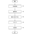
- the inspection system S performs ultrasonic flaw detection on the inner surface W1 of the object W by the flaw detection device 1 and the flaw detection probe 2 (step S1). At this time, the flaw detection probe 2 generates ultrasonic waves of 1 to 50 kHz and receives the ultrasonic waves reflected by the object W.
- the inspection system S acquires the signal of the flaw detection device 1 via the A / D converter 3 by the arithmetic unit 4 (step S2). Then, the inspection system S calculates the average value of the amplitude and phase of all the acquired signals by the arithmetic unit 4 (step S3).
- the inspection system S plots the average value of the acquired signals on the two-dimensional map by the arithmetic unit 4 (step S4). Subsequently, the inspection system S determines the defect based on the position where the average value of the signal is plotted on the two-dimensional map shown in FIG. 2 by the arithmetic unit 4 (step S5). That is, by determining at which position the average value of the above signals is plotted among the three areas divided by the defect discrimination threshold value and the position discrimination threshold value, the presence or absence of a defect, and if there is a defect, the inner surface W1 It is determined which of the outer surface W2 is present.
- the arithmetic unit 4 can discriminate a defect of the object W of the honeycomb structure from the signal of the flaw detection device 1 based on the defect discrimination threshold value. Therefore, it is possible to perform a homogeneous non-destructive inspection on the object W according to a uniform standard.
- the arithmetic unit 4 determines and stores the defect discrimination threshold value and the position discrimination threshold value by machine learning. Therefore, it is possible to easily set the defect discrimination threshold value and the position discrimination threshold value for each characteristic of the flaw detection device 1 and the shape and characteristics of the object W.
- the arithmetic unit 4 plots the signal acquired from the flaw detection device 1 on a two-dimensional two-dimensional map centered on the amplitude and phase. This makes it possible to use both the amplitude data and the phase data as the reference for discrimination.
- the arithmetic unit 4 can determine the defect position of the honeycomb structure from the signal of the flaw detection device 1 based on the position determination threshold value. Therefore, even when flaw detection is performed from the inner surface W1 of the object W, it is possible to discriminate defects on both the inner surface W1 and the outer surface W2.
- the pitch catch probe is used as the flaw detection probe 2, but the present disclosure is not limited to this.
- the flaw detection probe 2 it is possible to use those having various structures according to the shape of the object W.
- the frequency band of the flaw detection probe 2 is set to 1 to 50 kHz, but the present disclosure is not limited to this. It is also possible to appropriately change the frequency band depending on the shape and material of the object W.
- This disclosure can be applied to inspection systems.
Landscapes
- Physics & Mathematics (AREA)
- Health & Medical Sciences (AREA)
- Life Sciences & Earth Sciences (AREA)
- Chemical & Material Sciences (AREA)
- Analytical Chemistry (AREA)
- Biochemistry (AREA)
- General Health & Medical Sciences (AREA)
- General Physics & Mathematics (AREA)
- Immunology (AREA)
- Pathology (AREA)
- Acoustics & Sound (AREA)
- Investigating Or Analyzing Materials By The Use Of Ultrasonic Waves (AREA)
Abstract
この検査システム(S)は、ハニカム構造体の表面を探傷する探傷装置(1)と、探傷装置の信号に基づいて演算する演算装置(4)と、を有し、演算装置は、ハニカム構造体における欠陥の有無を判別する欠陥判別閾値に基づいて、欠陥の有無を判定する。
Description
本開示は、検査システムに関するものである。
本願は、2019年6月11日に日本に出願された特願2019-108543号に基づき優先権を主張し、その内容をここに援用する。
本願は、2019年6月11日に日本に出願された特願2019-108543号に基づき優先権を主張し、その内容をここに援用する。
一般的な構造物においては、表面の欠陥を超音波探傷等におより検査することが可能である(例えば、特許文献1)。しかしながら、構造が複雑であるハニカム構造の構造物においては、剥離等の欠陥の有無を検査するために、コインタッピングが実施されている。コインタッピングは、検査員が対象物をコインで叩き、その反射音から欠陥の有無を判別する手法である。
コインタッピングは検査員が反射音を聞くことで欠陥の有無を判別しており、検査精度が検査員の技量に大きく依存することとなる。したがって、検査員により検査の精度にムラが発生する。
本開示は、上述する問題点に鑑みてなされたもので、ハニカム構造体に対して、一律な基準により非破壊検査を実施することを目的とするものである。
本開示の一態様の検査システムは、ハニカム構造体の表面を探傷する探傷装置と、前記探傷装置の信号に基づいて演算する演算装置とを有し、前記演算装置は、前記ハニカム構造体における欠陥の有無を判別する欠陥判別閾値に基づいて、欠陥の有無を判定する。
上記一態様の検査システムにおいて、前記演算装置は、前記信号を予め記憶している二次元マップ上にプロットし、前記欠陥判別閾値は、前記二次元マップ上において線状または二次元形状として表されてもよい。
上記一態様の検査システムにおいて、前記演算装置は、予め試験片を探傷することにより取得した複数のデータを機械学習することにより前記二次元マップを作成してもよい。
上記一態様の検査システムにおいて、前記二次元マップは、前記信号の位相と振幅とに基づいて作成されてもよい。
上記一態様の検査システムにおいて、前記探傷装置は、1~50kHzの周波数の振動を発生させてもよい。
上記一態様の検査システムにおいて、前記演算装置は、前記ハニカム構造体における欠陥位置を判別する位置判別閾値に基づいて、欠陥位置を判別してもよい。
本開示によれば、探傷装置によりハニカム構造体を探傷し、さらに探傷装置の信号を欠陥判別閾値に基づいて演算装置が判別する。これにより、一律的な基準により、ハニカム構造体に対して均質な非破壊検査を行うことが可能である。
以下、本開示の一実施形態に係る検査システム及び検査方法を、図面を用いて説明する。
本開示の一実施形態に係る検査システムSは、対象物Wの非破壊検査を行う。対象物Wは、ハニカム構造体であり、正六角形のセルが複数形成される。対象物Wは、一方の面(外表面W2)に炭素繊維強化プラスチックの板材が貼り付けられ、他方の面(内表面W1)にガラス繊維強化プラスチックの板材が貼り付けられた略板状の部材とされる。また、対象物Wは、外表面W2が他の構造物と近接または接合されており、内表面W1のみにおいて探傷可能とされている。
図1に示すように、検査システムSは、探傷装置1、探傷プローブ2、A/D変換器3及び演算装置4を備えている。検査システムSは、探傷装置1及び探傷プローブ2を用いて対象物Wの内部の欠陥を検知する。
探傷装置1は、探傷プローブ2から発信する超音波の周波数等を制御する制御装置である。探傷装置1は、例えば、探傷プローブ2から発生させる超音波の周波数を1~50kHzに設定する。
探傷プローブ2は、発振器と受信器とを一体に備えるピッチキャッチプローブとされる。探傷プローブ2は、超音波を一方向に向けて発生させ、さらに反射した超音波を受信する。
A/D変換器3は、探傷装置1から発信されるアナログ信号をデジタル信号へと変換し、演算装置4へと送信する。
演算装置4は、探傷装置1からA/D変換器3を介して取得した信号に基づいて演算処理を行う。演算装置4は、例えばCPU、メモリ、ハードディスク等を備えるコンピュータとされる。演算装置4は、探傷装置1から取得した信号の振幅及び位相を平均化し、予め記憶している二次元マップに記録する。この二次元マップは、欠陥の有無が予め判明している試験片を探傷することにより取得した信号の振幅及び位相の各々の平均値を記録したものである。演算装置4は、欠陥のある部位において取得した信号の振幅及び位相の平均値をニューラルネットワーク等により機械学習することにより、欠陥判別閾値を決定している。なお、図2に示すように、二次元マップ上において、欠陥が内表面W1と外表面W2とのいずれの位置に発生しているかにより、取得した信号の振幅の平均値が異なっている。具体的には、外表面に欠陥がある場合には振幅が小さく、内表面に欠陥がある場合には振幅が大きくなる傾向がある。これに基づいて、演算装置4は、欠陥位置を判別する位置判別閾値を決定する。すなわち、演算装置4は、二次元マップ上において、機械学習により、欠陥の有無を判別する直線状の欠陥判別閾値(一次式)と、外表面W2にある欠陥と内表面W1にある欠陥とを判別する直線状の位置判別閾値(一次式)とを予め記憶している。
このような本実施形態に係る検査システムSにおける動作を、図3を参照して説明する。
検査システムSは、まず、探傷装置1及び探傷プローブ2により、対象物Wの内表面W1に対して超音波探傷を行う(ステップS1)。このとき、探傷プローブ2は、1~50kHzの超音波を発生させ、対象物Wにおいて反射された超音波を受信する。
検査システムSは、まず、探傷装置1及び探傷プローブ2により、対象物Wの内表面W1に対して超音波探傷を行う(ステップS1)。このとき、探傷プローブ2は、1~50kHzの超音波を発生させ、対象物Wにおいて反射された超音波を受信する。
次に、検査システムSは、演算装置4により、A/D変換器3を介して探傷装置1の信号を取得する(ステップS2)。そして、検査システムSは、演算装置4により、取得した全信号の振幅及び位相の平均値を算出する(ステップS3)。
そして、検査システムSは、演算装置4により、取得した信号の平均値を二次元マップ上にプロットする(ステップS4)。続いて、検査システムSは、演算装置4により、図2に示す二次元マップ上においてどの位置に上記信号の平均値がプロットされたかに基づいて欠陥を判別する(ステップS5)。すなわち、上記信号の平均値が欠陥判別閾値及び位置判別閾値により分けられる3つのエリアのうちどの位置にプロットされたかを判別することで、欠陥の有無、さらに欠陥がある場合には内表面W1と外表面W2とのいずれに存在しているかを判別する。
本実施形態によれば、演算装置4は、欠陥判別閾値に基づいて、探傷装置1の信号からハニカム構造体の対象物Wの欠陥を判別することが可能である。したがって、一律的な基準により、対象物Wに対して均質な非破壊検査を行うことが可能である。
また、本実施形態によれば、演算装置4は、機械学習により欠陥判別閾値及び位置判別閾値を決定し、記憶する。したがって、探傷装置1の特性や、対象物Wの形状、特性ごとに欠陥判別閾値及び位置判別閾値を容易に設定することが可能である。
また、本実施形態によれば、演算装置4は、探傷装置1から取得した信号を、振幅及び位相を軸とする二次元二次元マップ上にプロットする。これにより、振幅データ及び位相データの双方を判別の基準とすることが可能である。
また、本実施形態によれば、演算装置4は、位置判別閾値に基づいて、探傷装置1の信号からハニカム構造体の欠陥位置を判別することが可能である。したがって、対象物Wの内表面W1から探傷を行う場合であっても、内表面W1及び外表面W2の双方における欠陥を判別することが可能である。
なお、本開示は上記実施形態に限定されるものではなく、例えば以下のような変形例が考えられる。
(1)上記実施形態においては、探傷プローブ2として、ピッチキャッチプローブを用いるものとしたが、本開示はこれに限定されない。探傷プローブ2は、対象物Wの形状に合わせて様々な構造のものを用いることが可能である。
(1)上記実施形態においては、探傷プローブ2として、ピッチキャッチプローブを用いるものとしたが、本開示はこれに限定されない。探傷プローブ2は、対象物Wの形状に合わせて様々な構造のものを用いることが可能である。
(2)上記実施形態においては、探傷プローブ2における周波数帯域を1~50kHzとしたが、本開示はこれに限定されない。対象物Wの形状や材質により、周波数帯域を適切に変更することも可能である。
本開示は、検査システムに適用することができる。
1 探傷装置
2 探傷プローブ
3 A/D変換器
4 演算装置
S 検査システム
2 探傷プローブ
3 A/D変換器
4 演算装置
S 検査システム
Claims (6)
- ハニカム構造体の表面を探傷する探傷装置と、
前記探傷装置の信号に基づいて演算する演算装置と、
を有し、
前記演算装置は、前記ハニカム構造体における欠陥の有無を判別する欠陥判別閾値に基づいて、欠陥の有無を判定する検査システム。 - 前記演算装置は、前記信号を予め記憶している二次元マップ上にプロットし、
前記欠陥判別閾値は、前記二次元マップ上において線状または二次元形状として表される
請求項1記載の検査システム。 - 前記演算装置は、予め試験片を探傷することにより取得した複数のデータを機械学習することにより前記二次元マップを作成する請求項2記載の検査システム。
- 前記二次元マップは、前記信号の位相と振幅とに基づいて作成される請求項2または3記載の検査システム。
- 前記探傷装置は、1~50kHzの周波数の振動を発生させる請求項1~4のいずれか一項に記載の検査システム。
- 前記演算装置は、前記ハニカム構造体における欠陥位置を判別する位置判別閾値に基づいて、欠陥位置を判別する請求項1~5のいずれか一項に記載の検査システム。
Applications Claiming Priority (2)
| Application Number | Priority Date | Filing Date | Title |
|---|---|---|---|
| JP2019108543 | 2019-06-11 | ||
| JP2019-108543 | 2019-06-11 |
Publications (1)
| Publication Number | Publication Date |
|---|---|
| WO2020250583A1 true WO2020250583A1 (ja) | 2020-12-17 |
Family
ID=73781603
Family Applications (1)
| Application Number | Title | Priority Date | Filing Date |
|---|---|---|---|
| PCT/JP2020/017835 Ceased WO2020250583A1 (ja) | 2019-06-11 | 2020-04-24 | 検査システム |
Country Status (1)
| Country | Link |
|---|---|
| WO (1) | WO2020250583A1 (ja) |
Citations (5)
| Publication number | Priority date | Publication date | Assignee | Title |
|---|---|---|---|---|
| JP2003043016A (ja) * | 2001-05-22 | 2003-02-13 | Central Res Inst Of Electric Power Ind | 非破壊き裂深さ判定法 |
| JP2013088239A (ja) * | 2011-10-17 | 2013-05-13 | Ihi Corp | 合成構造体の欠陥面積率算出装置及び欠陥面積率算出方法 |
| JP2017129444A (ja) * | 2016-01-20 | 2017-07-27 | 株式会社日立パワーソリューションズ | 超音波検査方法及び装置 |
| US20170248549A1 (en) * | 2016-02-29 | 2017-08-31 | The Boeing Company | Method and system for non-destructive testing of composites |
| JP2018091685A (ja) * | 2016-12-01 | 2018-06-14 | 国立研究開発法人産業技術総合研究所 | 検査装置および検査方法 |
-
2020
- 2020-04-24 WO PCT/JP2020/017835 patent/WO2020250583A1/ja not_active Ceased
Patent Citations (5)
| Publication number | Priority date | Publication date | Assignee | Title |
|---|---|---|---|---|
| JP2003043016A (ja) * | 2001-05-22 | 2003-02-13 | Central Res Inst Of Electric Power Ind | 非破壊き裂深さ判定法 |
| JP2013088239A (ja) * | 2011-10-17 | 2013-05-13 | Ihi Corp | 合成構造体の欠陥面積率算出装置及び欠陥面積率算出方法 |
| JP2017129444A (ja) * | 2016-01-20 | 2017-07-27 | 株式会社日立パワーソリューションズ | 超音波検査方法及び装置 |
| US20170248549A1 (en) * | 2016-02-29 | 2017-08-31 | The Boeing Company | Method and system for non-destructive testing of composites |
| JP2018091685A (ja) * | 2016-12-01 | 2018-06-14 | 国立研究開発法人産業技術総合研究所 | 検査装置および検査方法 |
Similar Documents
| Publication | Publication Date | Title |
|---|---|---|
| US10481131B2 (en) | Ultrasonic test system, ultrasonic test method and method of manufacturing aircraft part | |
| CN112816556B (zh) | 一种缺陷检测方法、装置、设备和存储介质 | |
| KR101882838B1 (ko) | 적층체의 박리 검사 방법 및 박리 검사 장치 | |
| WO2011043050A1 (ja) | 超音波探傷検査の判定支援装置、判定支援方法、判定支援プログラム、及び該判定支援プログラムを記録したコンピュータ読取可能な記録媒体 | |
| CN109997039B (zh) | 复合材料的超声波探伤装置及方法 | |
| KR101830461B1 (ko) | 기계 부품 내부에 존재하는 결함의 방향을 측정하기 위한 방법 및 그 장치 | |
| CA2616900C (en) | Method for error-free checking of tubes for surface faults | |
| JP2018189550A (ja) | 超音波映像装置及び超音波映像生成方法 | |
| CN113960160B (zh) | 基于超声Lamb波紧凑阵列的损伤检测方法和装置 | |
| US11002711B2 (en) | Detection system, detection method, and server device | |
| JP2002243703A (ja) | 超音波探傷装置 | |
| JPH02129544A (ja) | 超音波探傷装置 | |
| JP2016118514A (ja) | 超音波探傷装置及び超音波探傷方法 | |
| JPS6229023B2 (ja) | ||
| JP3831285B2 (ja) | 超音波探傷装置及び超音波探傷方法 | |
| JP4482884B2 (ja) | 超音波探傷方法 | |
| JP4682921B2 (ja) | 超音波探傷方法及び超音波探傷装置 | |
| JP6761780B2 (ja) | 欠陥評価方法 | |
| JP4738243B2 (ja) | 超音波探傷システム | |
| JP2006300854A (ja) | 配管板厚測定装置 | |
| JPH0560732A (ja) | 接着・剥離判定用超音波装置 | |
| JP2025177068A (ja) | 超音波探傷装置及び超音波探傷方法 | |
| KR20180027274A (ko) | 유효탐지거리 계측 기능을 갖는 비파괴 검사 장치 | |
| JP2001004602A (ja) | 超音波探傷方法および装置 | |
| JPH0545345A (ja) | 超音波探傷方法及び装置 |
Legal Events
| Date | Code | Title | Description |
|---|---|---|---|
| 121 | Ep: the epo has been informed by wipo that ep was designated in this application |
Ref document number: 20822368 Country of ref document: EP Kind code of ref document: A1 |
|
| NENP | Non-entry into the national phase |
Ref country code: DE |
|
| 122 | Ep: pct application non-entry in european phase |
Ref document number: 20822368 Country of ref document: EP Kind code of ref document: A1 |
|
| NENP | Non-entry into the national phase |
Ref country code: JP |