WO2020250482A1 - 延伸装置 - Google Patents
延伸装置 Download PDFInfo
- Publication number
- WO2020250482A1 WO2020250482A1 PCT/JP2020/004387 JP2020004387W WO2020250482A1 WO 2020250482 A1 WO2020250482 A1 WO 2020250482A1 JP 2020004387 W JP2020004387 W JP 2020004387W WO 2020250482 A1 WO2020250482 A1 WO 2020250482A1
- Authority
- WO
- WIPO (PCT)
- Prior art keywords
- rail
- stretching
- link
- rail position
- film
- Prior art date
- Legal status (The legal status is an assumption and is not a legal conclusion. Google has not performed a legal analysis and makes no representation as to the accuracy of the status listed.)
- Ceased
Links
Images









Classifications
-
- B—PERFORMING OPERATIONS; TRANSPORTING
- B29—WORKING OF PLASTICS; WORKING OF SUBSTANCES IN A PLASTIC STATE IN GENERAL
- B29C—SHAPING OR JOINING OF PLASTICS; SHAPING OF MATERIAL IN A PLASTIC STATE, NOT OTHERWISE PROVIDED FOR; AFTER-TREATMENT OF THE SHAPED PRODUCTS, e.g. REPAIRING
- B29C55/00—Shaping by stretching, e.g. drawing through a die; Apparatus therefor
- B29C55/02—Shaping by stretching, e.g. drawing through a die; Apparatus therefor of plates or sheets
- B29C55/10—Shaping by stretching, e.g. drawing through a die; Apparatus therefor of plates or sheets multiaxial
- B29C55/12—Shaping by stretching, e.g. drawing through a die; Apparatus therefor of plates or sheets multiaxial biaxial
- B29C55/16—Shaping by stretching, e.g. drawing through a die; Apparatus therefor of plates or sheets multiaxial biaxial simultaneously
Definitions
- the present invention relates to a stretching device.
- the stretching device longitudinal stretching and transverse stretching can be performed, and performing these in order is called a sequential biaxial stretching method, and performing these at once is called a simultaneous biaxial stretching method.
- the simultaneous biaxial stretching method has advantages such as less scratching, a wider range of application of raw materials, stretching even at a high crystallization rate, and high vertical and horizontal uniformity of physical properties. ..
- Patent Document 1 Japanese Patent Application Laid-Open No. 2014-180779 describes a technique related to a stretching machine.
- the thermoplastic resin film stretching device covers the pair of link devices for transporting and stretching the thermoplastic resin film and the central portion of the pair of link devices, and the thermoplastic resin film.
- Each of the pair of link devices includes a support base, an annular outer rail in a plan view, and an inner side arranged on the inner peripheral side of the outer rail so as to face the outer rail. It has a rail, a first positioning means for positioning the inner rail at a first rail position, and a second positioning means for positioning the inner rail at a second rail position. ..
- the manufacturing cost when manufacturing a thin film using a stretching device, the manufacturing cost can be suppressed.
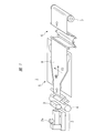
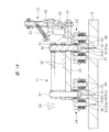
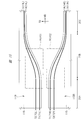
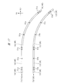
- FIG. 5 is a cross-sectional view taken along the line A1-A2 of the link shown in FIG. It is sectional drawing along the line A1-A3 of the link shown in FIG. It is a top view which shows the arrangement position of the rail in the stretching apparatus of one Embodiment. It is a partially enlarged plan view which shows the part of FIG. 8 enlarged.
- FIG. 1 is a schematic view showing the configuration of a thin film manufacturing system according to the present embodiment.
- the thin film manufacturing system 1 of the present embodiment shown in FIG. 1 includes an extruder (extruder, kneading extruder) 2, a T-die (die) 3, a raw fabric cooling device 4, and a stretching device (simultaneous two).
- a shaft stretching device) 5 a take-up device (take-up machine) 6, and a take-up device (wind-up machine) 7 are provided.
- the raw material is supplied into the extruder 2 from the raw material supply unit (raw material input port) 2a of the extruder 2.
- the raw material supplied to the extruder 2 is composed of a resin material (thermoplastic resin material, pellets), an additive, and the like.
- the extruder 2 transports (conveys) the raw materials supplied to the extruder 2 while kneading (mixing) them. For example, the raw material supplied into the extruder 2 is melted and kneaded while being fed forward by the rotation of the screw in the extruder 2.
- the kneaded product (molten resin) kneaded in the extruder 2 is supplied to the T die 3, passes through the T die 3, and is extruded from the slit of the T die 3 toward the raw fabric cooling device 4.
- the kneaded product (molten resin) supplied from the extruder 2 to the T die 3 is formed into a predetermined cross-sectional shape (here, a film shape) by passing through the T die 3.
- the kneaded product (molten resin) extruded from the T die 3 is cooled by the raw fabric cooling device 4 to become a film (sheet, resin film) 8.
- the film 8 is a film in a solidified state (solid state). More specifically, the film 8 is a thermoplastic resin film.
- the film 8 is supplied to the stretching device 5. Since the molded kneaded product (molten resin) is continuously extruded from the T die 3, the film 8 is continuously supplied to the stretching device 5.
- the film 8 supplied (conveyed) from the raw fabric cooling device 4 to the stretching device 5 is stretched in the MD direction and the TD direction by the stretching device 5.
- the film 8 that has been stretched (stretched) by the stretching device 5 is conveyed to the winding device 7 via the taking-up device 6 and is taken up by the take-up device 7.
- the film 8 wound on the winding device 7 is cut by a cutting machine (not shown) if necessary.
- the thin film can be manufactured using the thin film manufacturing system 1.
- the thin film manufacturing system 1 shown in FIG. 1 is an example, and various changes can be made depending on the characteristics of the thin film to be formed and the like.
- an extraction layer (not shown) may be provided in the vicinity of the take-up device 6 shown in FIG. 1, and the plasticizer (for example, paraffin) in the film 8 may be removed in the extraction tank.
- the stretching device 5 in the present embodiment stretches the film 8 in the MD direction and the TD direction while transporting the film 8 in the MD direction.
- the MD (Machine Direction) direction is the transport direction of the film, and is also called the vertical direction.
- the TD (Transverse Direction) direction is a direction that intersects with the film transport direction (MD direction in this case), and is also called a transverse direction.
- the MD direction and the TD direction are directions that intersect each other, and more specifically, directions that are orthogonal to each other.
- a stretching device 5 capable of simultaneously stretching a film in two directions (here, MD direction and TD direction) intersecting each other is called a simultaneous biaxial stretching device.
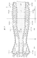
- FIG. 2 is a plan view showing the configuration of the stretching device 5 shown in FIG.
- FIG. 3 is a perspective perspective view of the stretching device 5, and FIG. 2 shows a case where the heat treatment unit 19 is seen through.
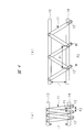
- FIG. 4 is a plan view schematically showing the link 11 and the rails 13 and 14 in the stretching device 5, but FIG. 4A shows a region where the rails 13 and 14 have a large distance from each other. In (b), a region where the distance between the rails 13 and 14 is smaller than that in (a) of FIG. 4 is shown.
- FIG. 5 is an enlarged plan view showing one of the plurality of links 11 shown in FIG. 3 in an enlarged manner.
- FIG. 6 is a cross-sectional view of the link 11 shown in FIG. 5 along the A1-A2 line
- FIG. 7 is a cross-sectional view of the link 11 shown in FIG. 5 along the A1-A3 line.
- the stretching device 5 has a pair of link devices 10 arranged apart from each other in a plan view.
- a link device 10R is referred to as a link device 10R and the other is referred to as a link device 10L.
- the link device 10R is arranged on the right side (R side) with respect to the transport direction (MD direction), and the link device 10L is located on the left side (L side) with respect to the transport direction (MD direction).
- MD direction transport direction
- L side transport direction
- the link device 10R and the link device 10L are separated from each other in the TD direction, and face each other in the TD direction with the film 8 interposed therebetween.
- the film 8 is arranged between the link device 10R and the link device 10L, and is conveyed in the MD direction between the link device 10R and the link device 10L.
- the portion between the link device 10R and the link device 10L can function as a transport unit for transporting the film 8.
- Each link device 10 (10R, 10L) has a plurality of links 11 connected so as to form an endless chain, a plurality of clips 12 attached to the plurality of links 11, and a movement of the plurality of links 11. It has a pair of rails 13, 14 serving as a route, sprockets 16, 17, 18 for driving the plurality of links 11, and a support base 15 for supporting the rails 13, 14.
- the link 11 constituting the link device 10R is referred to as a link 11R
- the link 11 constituting the link device 10L is referred to as a link 11L
- the clip 12 constituting the link device 10R is referred to as a clip 12R
- the clip 12 constituting the link device 10L is referred to as a clip 12L
- the rail 13 constituting the link device 10R is referred to as a rail 13R
- the rail 14 constituting the link device 10R is referred to as a rail 14R
- the rail 13 constituting the link device 10L is referred to as a rail 13L to form the link device 10L.
- the rail 14 will be referred to as a rail 14L.
- the sprockets 16, 17, 18 constituting the link device 10R shall be referred to as sprockets 16R, 17R, 18R, respectively, and the sprockets 16, 17, 18 constituting the link device 10L shall be referred to as sprockets 16L, 17L, 18L, respectively.
- the support base 15 constituting the link device 10R is referred to as a support base 15R, and the support base 15 constituting the link device 10L is referred to as a support base 15L.
- Clips 12R are attached to each of the plurality of links 11R constituting the link device 10R, and clips 12L are attached to each of the plurality of links 11L constituting the link device 10L.
- the clip 12 (12R, 12L) is a member (jig) that grips and grips the film 8, and can be regarded as a gripping member or a gripping member.
- the film 8 is gripped by the plurality of clips 12R of the link device 10R and the plurality of clips 12L of the link device 10L. That is, one end of the membrane 8 (the end on the right side with respect to the transport direction) is gripped by the plurality of clips 12R of the link device 10R, and the other end of the membrane 8 (the end on the left side with respect to the transport direction).
- Part is gripped by a plurality of clips 12L of the link device 10L.
- the film 8 is gripped by the plurality of links 11R of the link device 10R and the plurality of links 11L of the link device 10L via clips 12 (12R, 12L).
- the plurality of links 11R constituting the link device 10R are connected to each other so as to form an endless chain, and the plurality of links 11R connected to each other are rails in a state where they can travel along the rails 13R and 14R. It is arranged on 13R and 14R.
- the plurality of links 11L constituting the link device 10L are connected to each other so as to form an endless chain, and the plurality of links 11L connected to each other can travel along the rails 13L and 14L. It is arranged on the rails 13L and 14L.
- the rail 13R and the rail 14R are arranged in a ring shape in a pair, the rail 13R is arranged on the inner peripheral side, and the rail 14R is arranged on the outer peripheral side.
- the rail 13L and the rail 14L are arranged in a ring shape in a pair, the rail 13L is arranged on the inner peripheral side, and the rail 14L is arranged on the outer peripheral side. Therefore, the rail 13R is arranged on the inner peripheral side of the annular rail 14R in a plan view so as to face the rail 14R, and is arranged so as to face the rail 14L on the inner peripheral side of the annular rail 14L in a plan view.
- the rail 13L is arranged.
- the rail 13R and the rail 13L may be referred to as an inner rail, and the rail 14R and the rail 14L may be referred to as an outer rail.
- the stretching device 5 has three regions 20A, 20B, and 20C in a plan view.
- the region 20A is a preheating region (preheating region)
- the region 20B is a stretching region
- the region 20C is a heat fixing region.
- MD direction transport direction
- the area 20A, the area 20B, and the area 20C are arranged in order, the area 20A and the area 20B are adjacent to each other in the MD direction, the area 20B and the area 20C are adjacent to each other in the MD direction, and the MD.
- the inlet of the film 8 in the stretching device 5 (corresponding to the portion indicated by “IN” in FIGS.
- rance exists in the region 20A, and the inlet of the film 8 in the stretching device 5 exists.
- outlet exists in the region 20C.
- the direction from the inlet to the outlet of the film 8 in the stretching device 5 corresponds to the transport direction (MD direction) of the film 8.
- the stretching device 5 further includes a heat treatment section (heat treatment device) 19 for covering the central portion of the pair of link devices 10R and 10L and performing a heat treatment on the film 8.
- FIG. 2 shows an example in which an oven is used as the heat treatment unit 19. A part (central portion) of each of the link devices 10R and 10L is arranged in the heat treatment section 19. The film 8 passes through the heat treatment section 19 while being held by the link device 10R and the link device 10L.
- the link devices 10R and 10L are covered by the heat treatment unit 19 in a part of the region 20A, the entire region 20B, and a part of the region 20C. Therefore, in the region 20B (stretched region), the entire link devices 10R and 10L are covered with the heat treatment section 19. Since the film 8 is stretched in the TD direction and the MD direction in the region 20B (the region covered by the heat treatment section 19), the film 8 is stretched (in the TD direction and the MD direction) while being heated (heat treated) in the heat treatment section 19. Stretching treatment) will be performed.
- the link devices 10R and 10L have a region covered by the heat treatment unit 19 and a region not covered, and the vicinity of the inlet of the film 8 (sprocket 16 and 17 are arranged). In the vicinity of), the link devices 10R and 10L are not covered with the heat treatment section 19. Further, in the region 20C (heat fixing region), the link devices 10R and 10L have a region covered by the heat treatment unit 19 and a region not covered, and the vicinity of the outlet of the film 8 (the sprocket 18 is arranged). The link devices 10R and 10L are not covered with the heat treatment section 19.
- the film 8 passes through the regions 20A, 20B, and 20C, the film 8 passes through the heat treatment section 19, so that the film 8 can be heated to a desired temperature. Therefore, the stretching treatment of the film 8 can be performed at a temperature suitable for the stretching treatment.
- Both the pair of rails 13R and 14R included in the link device 10R and the pair of rails 13L and 14L included in the link device 10L are arranged in an annular shape over the regions 20A, 20B and 20C.
- the side facing the film 8 is referred to as the “membrane side”
- the side opposite to the “membrane side” is referred to as the “return side”.
- the sprockets 16R, 17R, 18R are arranged inside the annular rail 13R (inner rail) in a plan view, and the sprockets 16R, 17R are arranged on the inlet side (region 20A).
- the sprocket 18R is arranged on the outlet side (region 20C).
- the sprockets 16L, 17L, 18L are arranged inside the annular rail 13L (inner rail) in a plan view, and the sprockets 16L, 17L thereof are on the inlet side (region 20A).
- the sprocket 18L is arranged and is arranged on the outlet side (region 20C).
- the sprockets 16R, 17R, 18R are engaged with a plurality of links 11R, and the rotation of the sprockets 16R, 17R, 18R exerts a driving force on the plurality of links 11R, thereby forming the link device 10R.
- the link 11R can move along the rails 13R and 14R.
- the sprockets 16L, 17L, 18L are engaged with a plurality of links 11L, and the rotation of the sprockets 16L, 17L, 18L causes a driving force to act on the plurality of links 11L, thereby causing the link device 10L.
- a plurality of constituent links 11L can move along the rails 13L and 14L.
- each of the link devices 10R and 10L the plurality of links 11 are arranged on the rails 13 and 14 in a state where the pitches of the adjacent links 11 can be changed.
- one end of each link 11 is arranged on the rail 13 so as to be movable along the rail 13, and the other end is arranged on the rail 14 and on the rail 14.
- the clips 12 are arranged so as to be movable along the rails, and clips 12 are attached to one end of each link 11 (the end on the side arranged on the rail 14). Therefore, when the link 11 moves, the clip 12 moves together with the link 11. Therefore, in each of the link devices 10R and 10L, when the pitches of the adjacent links 11 change, the pitches of the adjacent clips 12 also change accordingly. That is, as the pitch of the adjacent links 11 increases, the pitch of the adjacent clips 12 also increases accordingly.
- the specific structure of each link 11 will be described in more detail later.
- the pitch P1 between the links 11 adjacent to each other can be changed according to the distance (separation distance) L1 between the rail 13 and the rail 14, and therefore the clips 12 adjacent to each other.
- the pitch P2 of the above can also be changed according to the distance (separation distance) L1 between the rail 13 and the rail 14. Therefore, in each of the link devices 10R and 10L, the pitch P1 of the links 11 adjacent to each other can be adjusted by adjusting the distance L1 of the rails 13 and 14, whereby the pitchs of the clips 12 adjacent to each other can be adjusted. P2 can be adjusted. This is because, as can be seen from FIG. 4, in each of the link devices 10R and 10L, the smaller the distance L1 between the rails 13 and 14, the larger the angle formed by the adjacent links 11, and the pitch P1 of the adjacent links 11 becomes larger. Because it gets bigger.
- the distance L1 between the rail 13 and the rail 14 is set.
- the pitch P1 of the adjacent links 11 is larger than that of the larger region (corresponding to (a) in FIG. 4), and therefore the pitch P2 of the adjacent clips 12 is also larger. Therefore, in each of the link devices 10R and 10L, if a region (corresponding to the region 20B) in which the distance L1 between the rails 13 and 14 gradually decreases in the transport direction (MD direction) is provided, the regions are adjacent to each other.
- the pitch P1 of the matching link 11 gradually increases, and the pitch P2 of the adjacent clips 12 gradually increases accordingly.
- the film 8 supplied (conveyed) from the original fabric cooling device 4 to the stretching device 5 is attached to a clip 12 (11R, 11L) provided on each of the link devices 10R and 10L at the inlet of the stretching device 5. It is gripped by (12R, 12L). That is, one end of the membrane 8 (the end on the right side with respect to the transport direction) is gripped by the clip 12R of the link device 10R, and the other end of the membrane 8 (the end on the left side with respect to the transport direction). Is gripped by the clip 12L of the link device 10L.
- the film 8 gripped by the clips 12R and 12L is conveyed together with the clips 12R and 12L in the MD direction from the inlet to the outlet of the stretching device 5, so that the region 20A (preheating region) and the region 20B (stretching) The region) and the region 20C (heat fixing region) are passed in order.
- the film 8 gripped by the clips 12R and 12L is heated while passing through the regions 20A, 20B and 20C, and is stretched in the MD direction and the TD direction as it passes through the regions 20B.
- the film 8 gripped by the clips 12R, 12L reaches the outlet of the stretching device 5, where it is removed from the clips 12R, 12L.
- the film 8 removed from the clips 12R and 12L is conveyed to the take-up device 6 from the outlet of the stretching device 5, and is conveyed from the take-up device 6 to the take-up device 7 to be taken up.
- the distance (distance in the TD direction) L2 between the rail 14R of the link device 10R and the rail 14L of the link device 10L is substantially constant. Therefore, in the region 20A, the film 8 is not stretched in the TD direction. Therefore, in the region 20A, the width (dimension in the TD direction) of the conveyed film 8 does not change and remains constant.
- the distance (L1) between the rail 13R and the rail 14R on the film side of the link device 10R is almost constant. Therefore, in the region 20A, the pitch (P1) of the link 11R on the film side of the link device 10R is substantially constant, and therefore the pitch (P2) of the clip 12R on the film side of the link device 10R is also substantially constant. That is, in the region 20A, the pitch (P2) of the clip 12R that grips the film 8 is substantially constant. Further, in the region 20A, the distance (L1) between the rail 13L and the rail 14L on the film side of the link device 10L is substantially constant.
- the pitch (P1) of the link 11L on the film side of the link device 10L is substantially constant, and therefore the pitch (P2) of the clip 12L on the film side of the link device 10L is also substantially constant. That is, in the region 20A, the pitch (P2) of the clip 12L that grips the film 8 is substantially constant. Therefore, in the region 20A, the film 8 is not stretched in the MD direction. Therefore, in the region 20A, the stretching treatment for the film 8 is not performed in either the TD direction or the MD direction.
- the distance (spacing in the TD direction) L2 between the rail 14R of the link device 10R and the rail 14L of the link device 10L gradually increases as the transport direction (MD direction) progresses. Therefore, in the region 20B, the distance between the clip 12R that grips one end of the film 8 and the clip 12L that grips the other end of the film 8 as it advances in the transport direction (MD direction) ( Distance in the TD direction) gradually increases. As a result, in the region 20B, as the film 8 advances in the transport direction (MD direction), the film 8 is pulled and stretched in the TD direction by the clips 12R and 12L, so that the film 8 is stretched in the TD direction. Therefore, in the region 20B, the width (dimension in the TD direction) of the film 8 gradually increases as it advances in the transport direction (MD direction).
- the distance (L1) between the rail 13R and the rail 14R on the film side of the link device 10R gradually decreases as the link device 10R advances in the transport direction (MD direction), and the link device The distance (L1) between the rail 13L and the rail 14L on the film side of 10L is also gradually reduced. Therefore, in the region 20B, the pitch (P1) of the link 11R on the film side of the link device 10R gradually increases as it advances in the transport direction (MD direction), and accordingly, the clip 12R on the film side of the link device 10R Pitch (P2) also gradually increases. That is, in the region 20B, the pitch (P2) of the clip 12L that grips the film 8 gradually increases.
- the pitch (P1) of the link 11L on the film side of the link device 10L gradually increases as the transport direction (MD direction) progresses, and accordingly, the clip 12L on the film side of the link device 10L
- the pitch (P2) also gradually increases. That is, in the region 20B, the pitch (P2) of the clip 12R that grips the film 8 gradually increases.
- the film 8 is pulled and stretched in the MD direction by the clip 12R as it advances in the transport direction (MD direction), and is pulled and stretched in the MD direction by the clip 12L, so that the film 8 is stretched. 8 will be stretched in the MD direction.
- the film 8 is stretched (stretched) in the TD direction and the MD direction as it advances in the transport direction (MD direction). That is, in the region 20B, the stretching treatment in the TD direction and the MD direction is applied to the film 8.
- the distance (distance in the TD direction) L2 between the rail 14R of the link device 10R and the rail 14L of the link device 10L is substantially constant. Therefore, in the region 20C, the film 8 is not stretched in the TD direction. Therefore, in the region 20C, the width (dimension in the TD direction) of the conveyed film 8 does not change and remains constant.
- the distance (L1) between the rail 13R and the rail 14R on the film side of the link device 10R is almost constant. Therefore, in the region 20C, the pitch (P1) of the link 11R on the film side of the link device 10R is substantially constant, and therefore the pitch (P2) of the clip 12R on the film side of the link device 10R is also substantially constant. That is, in the region 20C, the pitch (P2) of the clip 12R that grips the film 8 is substantially constant. Further, in the region 20C, the distance (L1) between the rail 13L and the rail 14L on the film side of the link device 10L is substantially constant.
- the pitch (P1) of the link 11L on the film side of the link device 10L is substantially constant, and therefore the pitch (P2) of the clip 12L on the film side of the link device 10L is also substantially constant. That is, in the region 20C, the pitch (P2) of the clip 12L that grips the film 8 is substantially constant. Therefore, in the region 20C, the film 8 is not stretched in the MD direction. Therefore, in the region 20C, the stretching treatment for the film 8 is not performed in either the TD direction or the MD direction.
- the pitch (P1) of the link 11R on the film side of the link device 10R is constant, and the pitch (P1) of the link 11L on the film side of the link device 10L is also constant.
- the pitch of the link 11R (P1) on the film side of the link device 10R and the pitch (P1) of the link 11L on the film side of the link device 10L are gradually increased.
- the pitch (P1) of the link 11R on the film side of the link device 10R is constant, and the pitch (P1) of the link 11L on the film side of the link device 10L is also constant.
- the pitch (P1) of the link 11R in the region 20C is larger than the pitch (P1) of the link 11R in the region 20A, and the pitch of the link 11L in the region 20C.
- (P1) is larger than the pitch (P1) of the link 11L in the region 20A.
- the pitch (P2) of the clip 12R in the region 20C is larger than the pitch (P2) of the clip 12R in the region 20A on each film side of the link devices 10R and 10L, and the clip in the region 20C.
- the pitch (P2) of 12L is larger than the pitch (P2) of the clip 12L in the region 20A.
- the distance between the rails 13R and 14R (L1) in the region 20C is smaller than the distance between the rails 13R and 14R (L1) in the region 20A on the film side of the link devices 10R and 10L, respectively.
- the distance between the rails 13L and 14L in the area 20C (L1) is smaller than the distance between the rails 13L and 14L in the area 20A (L1).
- each link 11 includes an upper link plate 22, a lower link plate 23, and rail holders 24 and 25.
- Each of the upper link plate 22 and the lower link plate 23 is a plate-shaped member that extends linearly in a plan view.
- a common shaft 26 is inserted into one end of the upper link plate 22 and the lower link plate 23, and the upper link plate 22 and the lower link plate 23 are at the center of the shaft 26. Is connected via a shaft 26 in a rotatable state with the axis of rotation.
- a clip 12 is attached to one end of the lower link plate 23. In the lower link plate 23, the shaft 26 is inserted between one end to which the clip 12 is attached and the other end.
- Each clip 12 has a main body portion 31, a grip portion 32 capable of moving up and down with respect to the main body portion 31, a spring portion 33 for moving the grip portion 32 up and down, and the like. Since the grip portion 32 moves up and down by the force of the portion 33 and the like, the film 8 can be sandwiched and gripped by the main body portion 31 and the grip portion 32.
- the shaft 27 is inserted into the other end of the upper link plate 22 (the end opposite to the side into which the shaft 26 is inserted).
- the shaft 27 connects the links 11 adjacent to each other. Specifically, among the links 11 adjacent to each other, a common shaft 27 is inserted into the upper link plate 22 of one link 11 and the lower link plate 23 of the other link 11. As a result, among the links 11 adjacent to each other, the upper link plate 22 of one link 11 and the lower link plate 23 of the other link 11 can rotate around the center of the shaft 27 as a rotation axis. It is connected via 27. Further, an engaging portion 28 that is engaged with the sprockets 16, 17, 18 is attached to the other end of the upper link plate 22.
- a rail holder 25 is attached to the lower end of the shaft 26 in a state in which it can rotate around the center of the shaft 26 as a rotation axis. Further, a rail holder 24 is attached to the lower end of the shaft 27 in a state in which the rail holder 24 can rotate around the center of the shaft 27 as a rotation axis.
- the rail holder 24 is arranged so as to cover the rail 13, and the rail holder 25 is arranged so as to cover the rail 14.
- the rail holder 24 has a pair of bearing rollers 34 and 35, and the rail 13 is sandwiched between the bearing rollers 34 and the bearing rollers 35 from both sides.
- the rail holder 25 has a pair of bearing rollers 36 and 37, and the rail 14 is sandwiched between the bearing rollers 36 and the bearing rollers 37 from both sides. Therefore, the rail holder 24 is arranged so as to cover the rail 13 so as to be movable along the rail 13. Further, the rail holder 25 is arranged so as to cover the rail 14 in a state of being movable along the rail 14.
- the driving force due to the rotation of the sprockets 16, 17, 18 acts on the link 11, and the rail holders 24, 25 move along the rails 13, 14, so that the link 11 moves along the rails 13, 14.
- the upper link plate 22 and the lower link plate 23 rotate in accordance with the change. Therefore, the angle ⁇ formed by the upper link plate 22 and the lower link plate 23 changes.
- the pitch (P1) of the adjacent links 11 changes according to the distance (L1) between the rails 13 and 14.
- the pitch (P1) of the adjacent links 11 can be defined with reference to the center of the shaft 26. That is, the pitch (P1) of the adjacent links 11 can be defined as the distance between the centers of the shafts 26 included in each of the adjacent links 11.
- the pitch (P1) of the adjacent clips 12 is substantially the same as the pitch (P2) of the adjacent links 11.
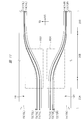
- FIG. 8 is a plan view showing the arrangement positions of the rails 13 and 14, and shows a state in which the rail 14 is arranged at the rail position 71 and the rail 13 is arranged at the rail position 72 in each of the link devices 10L and 10R.
- 9 is a partially enlarged plan view showing the region RG1 surrounded by the alternate long and short dash line in FIG. 8 in an enlarged manner
- FIG. 10 is an enlarged portion showing the region RG2 surrounded by the alternate long and short dash line in FIG. It is an enlarged plan view.
- the rail position 73 is shown by a dotted line.
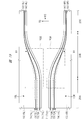
- FIG. 11 is a plan view showing the arrangement positions of the rails 13 and 14 when the arrangement position of the rail 13 is changed from the state of FIG. 8, and the rail 14 is arranged at the rail position 71 in each of the link devices 10L and 10R.
- the state in which the rail 13 is arranged at the rail position 73 is shown.
- FIG. 12 is a partially enlarged plan view showing the region RG3 surrounded by the alternate long and short dash line in FIG. 11 in an enlarged manner
- FIG. 13 is an enlarged portion showing the region RG4 surrounded by the alternate long and short dash line in FIG. It is an enlarged plan view.
- the rail position 72 is shown by a dotted line.
- FIG. 14 is a cross-sectional view of the link 11 similar to that of FIG. 6, but FIG. 6 corresponds to a cross-sectional view when the rail 13 is arranged at the rail position 72 (in the case of FIGS. 8 to 10). On the other hand, FIG. 14 corresponds to a cross-sectional view when the rail 13 is arranged at the rail position 73 (in the case of FIGS. 11 to 13).
- the link devices 10R and 10L are each provided with a support base 15.
- the support base 15 for the link device 10R that is, the support base 15R that supports the rails 13R and 14R
- the support base 15 for the link device 10L that is, the support base that supports the rails 13L and 14L
- 15L are provided separately, and will be described below based on this case.
- the rails 13, 14 (that is, rails 13R, 14R) of the link device 10R are arranged on the support base 15 (that is, the support base 15R) of the link device 10R, and are supported by a fixing member such as a screw 41 (see FIG. 6). It is held or fixed to the table 15 (15R).
- the rails 13, 14 (that is, rails 13L, 14L) of the link device 10L are arranged on the support base 15 (that is, the support base 15L) of the link device 10L, and are supported by a fixing member such as a screw 41 (see FIG. 6). It is held or fixed to the table 15 (15L).
- the following description can be applied to the support base 15 and rails 13, 14 (that is, the support base 15R and rails 13R, 14R) constituting the link device 10R, and the support base 15 and rails constituting the link device 10L. It can be applied to 13 and 14 (that is, the support base 15L and the rails 13L and 14L).
- the support base 15 is a member that supports the rails 13 and 14, and is made of, for example, a plate-shaped (flat plate-shaped) member (metal plate, etc.). As shown in FIG. 6, the support base 15 is provided with a plurality of hole portions (screw hole portions) 51. A screw groove is formed on the inner surface of each hole 51 as needed.
- the rail 14 is provided with a plurality of holes (screw holes) 61 penetrating the rail 14, and the rail 13 is provided with a plurality of holes (screw holes) 62 penetrating the rail 13. Has been done. If necessary, screw grooves are formed on the inner side surfaces of the holes 61 and 62.
- the rail 14 is positioned by inserting a screw 41 into the hole 61 of the rail 14 and the hole 51 of the support base 15 from the upper surface side of the rail 14, and the rail 14 is fixed or held on the support base 15. Further, by inserting a screw 41 into the hole 62 of the rail 13 and the hole 51 of the support base 15 from the upper surface side of the rail 13, the rail 13 is positioned and the rail 13 is fixed or held on the support base 15. There is.
- the rail 13 can be removed from the support base 15 by removing (removing) the screw 41 inserted into the hole 62 of the rail 13.
- the rail 14 can be removed from the support base 15 by removing (removing) the screw 41 inserted into the hole 61 of the rail 14.
- the screws 41 do not come into contact with the links 11 (rail holders 24 and 25) arranged on the rails 13 and 14 while the rails 13 and 14 are fixed to the support base 15 by the screws 41.
- the screw 41 does not protrude from the upper surfaces of the rails 13 and 14. As a result, it is possible to accurately prevent the screw 41 from interfering with the movement of the link 11.
- the hole portion 51 is formed on the upper surface side of the support base 15, and reaches from the upper surface of the support base 15 to the middle of the thickness of the support base 15, but the hole portion 51 is formed. It does not penetrate the support base 15.
- the hole 51 may penetrate the support base 15, but in that case, bolts can be used as the screws 41, and the rails 13 and 14 are fixed to the support base 15 by bolts and nuts. be able to.
- the plurality of holes 51 formed in the support base 15 include a plurality of holes 51a for positioning the rail 14 at a predetermined rail position 71 and a plurality of holes for positioning the rail 13 at a predetermined rail position 72. Although it includes the portion 51b, it also includes a plurality of hole portions 51c for positioning the rail 13 at another rail position 73.
- the rail 14 is arranged at a position where the hole 61 of the rail 14 is aligned with the hole 51a of the support base 15, and the screw 41 is inserted into the hole 61 of the rail 14 and the hole 51a of the support base 15.
- the rail 14 is fixed to the support base 15, and the arrangement position of the rail 14 is referred to as the rail position 71.
- the hole portion 51a of the support base 15 can function as a positioning means (positioning portion) for determining the position of the rail 14 to be arranged on the support base 15, and by using the hole portion 51a, the rail 14 can be formed. It is positioned and fixed at the rail position 71.
- a plurality of hole portions 51a are arranged so as to be lined up along the rail position 71.
- the rail 13 is arranged at a position where the hole 62 of the rail 13 is aligned with the hole 51b of the support base 15, and the screw 41 is inserted into the hole 62 of the rail 13 and the hole 51b of the support base 15.
- the rail 13 is fixed to the support base 15, and the arrangement position of the rail 13 is referred to as the rail position 72.
- the hole portion 51b of the support base 15 can function as a positioning means (positioning portion) for determining the position of the rail 13 to be arranged on the support base 15, and by using the hole portion 51b, the rail 13 can be formed. It is positioned and fixed at the rail position 72.
- a plurality of hole portions 51b are arranged so as to be lined up along the rail position 72.
- Each of the rails 13 and 14 is an annular rail in a plan view.
- Each of the rails 13 and 14 can be a continuous (integral) annular rail, but by arranging (arranging) the rail members divided into a plurality of rails so as to be connected in an annular shape, the rails 13 and 14 are annular. Rails (13, 14) can be formed. This facilitates the manufacture of rail members and facilitates the preparation of annular rails (13, 14).
- the arrangement position of the rail 13 on the support base 15 can be changed. That is, although the rail 13 is arranged at the rail position 72 on the support base 15, the arrangement position of the rail 13 can be changed from the rail position 72 to the rail position 73. That is, the state of FIGS. 6 and 8 to 10 can be changed to the state of FIGS. 11 to 14. Therefore, in the support base 15, in addition to a plurality of hole portions 51a for positioning the rail 14 at the rail position 71 and a plurality of hole portions 51b for positioning the rail 13 at the rail position 72, further. A plurality of holes 51c for positioning the rail 13 at the rail position 73 are also formed.
- the rail 13 is arranged at a position where the hole 62 of the rail 13 is aligned with the hole 51c of the support base 15, and the screw 41 is inserted into the hole 62 of the rail 13 and the hole 51c of the support base 15.
- the rail 13 can also be fixed to the support base 15, and the arrangement position of the rail 13 at that time is referred to as a rail position 73.
- the hole portion 51c of the support base 15 can function as a positioning means (positioning portion) for determining the position of the rail 13 arranged on the support base 15, and the rail 13 can be railed by using the hole portion 51c. It can be positioned and fixed at position 73.
- a plurality of hole portions 51c are arranged so as to be lined up along the rail position 73.
- the arrangement position of the rail 13 on the support base 15 can be changed from the rail position 72 to the rail position 73, and the rail position 73 can be changed to the rail position 72.
- the arrangement position of the rail 14 on the support base 15 is fixed. That is, the position of the rail 14 arranged on the support base 15 is not changed. Therefore, as a hole 51 for positioning the rail 14, a hole 51a for arranging the rail 14 at the rail position 71 is provided, but a hole for arranging the rail 14 at a position other than the rail position 71.
- the portion 51 is not provided on the support base 15. However, at the time of maintenance or the like, the rail 14 can be removed from the support base 15 by removing (pulling out) the screw 41 that screws the rail 14.
- the rail 14 is arranged at the rail position 71 and the rail 13 is arranged at either the rail position 72 or the rail position 73, the rail 14 is arranged at the rail position 71 and the rail 13 is arranged at the rail position 72. (In the case of FIGS. 6 and 8 to 10) and when the rail 14 is arranged at the rail position 71 and the rail 13 is arranged at the rail position 73 (in the case of FIGS. 11 to 14). possible.
- the rail 14 is arranged at the rail position 71 and the rail 13 is arranged at the rail position 72 (in the case of FIGS. 6 and 8 to 10)
- the rail 14 is arranged at the rail position 71 and the rail 13 is arranged. Is arranged at the rail position 73 (in the case of FIGS.
- the stretching ratio of the film 8 in the MD direction can be changed. That is, when it becomes necessary to change the draw ratio of the film 8 in the MD direction, the arrangement position of the rail 13 on the support base 15 is changed from the rail position 72 to the rail position 73.
- the position of the rail 13 on the support base 15 can be changed from the rail position 72 to the rail position 73 as follows. That is, first, the screw 41 is removed (pulled out) from the rail member (rail 13) screwed to the rail position 72, the rail member (rail 13) is moved to the rail position 73, and then the rail member. A screw 41 is inserted into the hole 62 of the (rail 13) and the hole 51c of the support base 15, and the rail member (rail 13) is screwed to the rail position 73.
- the rail 13 arranged at the rail position 72 and the rail 13 arranged at the rail position 73 can be formed by using the same (common) rail member, the rail for the rail position 73 It is not necessary to prepare the members separately. Therefore, the manufacturing cost of the stretching device 5 can be suppressed.
- a rail member for the rail position 73 may be prepared in advance in addition to the rail member arranged at the rail position 72.
- the screw 41 is removed (pulled out) from the rail member (rail 13) screwed to the rail position 72, the rail member is removed from the support base 15, and then a separately prepared rail member (rail 13) is removed.
- a screw 41 is inserted into the hole 62 of the rail member (rail 13) and the hole 51c of the support base 15, and the rail member (rail 13) is screwed at the rail position 73. Stop.
- the pitch (P1) of the link 11 changes according to the distance (L1) between the rails 13 and 14, and the pitch (P2) of the clip 12 that grips the film 8 also changes accordingly.
- the film 8 is gripped by the clip 12, and the pitch (P2) of the clip 12 at that time is assumed to be ⁇ 1.
- the pitch (P2) of the clip 12 that grips the film 8 is ⁇ 1.
- the pitch (P2) of the clip 12 that grips the film 8 gradually increases as it advances in the transport direction (MD direction).
- the pitch (P2) of the clip 12 that grips the film 8 after the stretching treatment is performed in the region 20B (stretched region), that is, the pitch (P2) of the clip 12 that grips the film 8 in the region 20C (heat fixing region) Is assumed to be ⁇ 2.
- ⁇ 2 is larger than ⁇ 1, and ⁇ 1 ⁇ 2 holds.
- the pitch (P2) of the clip 12 that grips the film 8 is substantially constant in the region 20A and is ⁇ 1, gradually increases from ⁇ 1 to ⁇ 2 in the region 20B, and is substantially constant in the region 20C. Yes, it is ⁇ 2.
- the rail 14 When the rail 14 is arranged at the rail position 71 and the rail 13 is arranged at the rail position 72 (in the case of FIGS. 6 and 8 to 10), the rail 14 is arranged at the rail position 71 and the rail 13 is arranged. Is arranged at the rail position 73 (in the case of FIGS. 11 to 14), and the stretching ratio of the film 8 in the MD direction is different.
- the draw ratio ⁇ 2 / ⁇ 1
- the draw ratio of the film 8 in the MD direction (). ⁇ 2 / ⁇ 1) is 5 times. Therefore, when it is desired to increase the draw ratio of the film 8 in the MD direction to 7 times, the position of the rail 13 on the support base 15 is set to the rail position 72, and when it is desired to increase the draw ratio of the film 8 in the MD direction to 5 times, the support is provided.
- the arrangement position of the rail 13 on the table 15 may be changed to the rail position 73.
- the numerical value of the draw ratio in the MD direction shown here is an example, and is not limited to this.
- the film 8 is gripped by the clip 12, and the width (dimension in the TD direction) of the film 8 at that time is assumed to be the width ⁇ 1.
- the width of the film 8 is substantially the same as the distance (distance in the TD direction) between the clip 12R of the link device 10R that grips the film 8 and the clip 12L of the link device 10L.
- the width (dimension in the TD direction) of the film 8 gradually increases in the region 20B (stretched region).
- the width of the film 8 after the stretching treatment is performed in the region 20B (stretched region), that is, the width of the film 8 (dimension in the TD direction) in the region 20C (heat fixing region) is assumed to be ⁇ 2.
- ⁇ 2 is larger than ⁇ 1, and ⁇ 1 ⁇ 2 holds.
- the width of the film 8 is substantially constant in the region 20A (preheating region) and is ⁇ 1, gradually increases from ⁇ 1 to ⁇ 2 in the region 20B (stretched region), and gradually increases in the region 20C (heat fixing region). , Is almost constant and is ⁇ 2.
- the rail 14 When the rail 14 is arranged at the rail position 71 and the rail 13 is arranged at the rail position 72 (in the case of FIGS. 6 and 8 to 10), the rail 14 is arranged at the rail position 71 and the rail 13 is arranged. Is arranged at the rail position 73 (in the case of FIGS. 11 to 14), the draw ratio of the film 8 in the TD direction is the same. This is because even if the arrangement position of the rail 13 is changed from the rail position 72 to the rail position 73, the arrangement position of the rail 14 is not changed from the rail position 71.
- the distance (distance in the TD direction) between the clip 12R of the link device 10R that grips the film 8 and the clip 12L of the link device 10L is the rail 14R (outer rail) of the link device 10R and the rail 14L (outside) of the link device 10L. It is defined by the distance between the rail and the rail (the distance in the TD direction). Therefore, it is not the distance between the rails 13R and 14R (L1) in the link device 10R and the distance between the rails 13L and 14L (L1) in the link device 10L that affects the stretching ratio of the film 8 in the TD direction, but the link device.
- the distance (L2) between the rail 14R of the 10R and the rail 14L of the link device 10L is not the distance between the rail 14R of the 10R and the rail 14L of the link device 10L.
- the stretching ratio of the film 8 in the TD direction is not changed.
- the rail 14 is arranged at the rail position 71 and the rail 13 is arranged at the rail position 72 (in the case of FIGS. 6 and 8 to 10)
- the rail 14 is arranged at the rail position 71 and
- the draw ratio ( ⁇ 2 / ⁇ 1) of the film 8 in the TD direction is 7 times.
- the numerical value of the draw ratio in the TD direction shown here is an example, and is not limited to this.
- the rail position 71, the rail position 72, and the rail position 73 in the link device 10R are referred to as the rail position 71R, the rail position 72R, and the rail position 73R, respectively, and the rail position 71, the rail position 72, and the rail position 73 in the link device 10L.
- the rail position 71L, rail position 72L, and rail position 73L are referred to as rail position 71L, rail position 72L, and rail position 73L, respectively.
- the rail 14L is arranged at the rail position 71L and the rail 13R is arranged in the link device 10L. It is arranged at the rail position 72L.
- the rail 14R is arranged at the rail position 71R and the rail 13R is arranged at the rail position 73R in the link device 10R
- the rail 14L is arranged at the rail position 71L and the rail is arranged in the link device 10L.
- 13L is arranged at the rail position 73L.
- the arrangement position of the rail 13R is changed from the rail position 72R to the rail position 73R in the link device 10R
- the arrangement position of the rail 13L is changed from the rail position 72L to the rail position 73L in the link device 10L.
- the stretching ratio ( ⁇ 2 / ⁇ 1) in the MD direction on the left side of the film 8 (link device 10L side) and the stretching ratio ( ⁇ 2 / ⁇ 1) in the MD direction on the right side of the film 8 (link device 10R side) are changed. Since they can be matched, the stretching treatment of the film 8 can be performed accurately.
- the pitch P1 of the link 11 in the link device 10R and the pitch P1 of the link 11 in the link device 10L are the same when the positions in the MD direction are the same. Therefore, when the positions in the MD direction are the same, it is preferable that the pitch P2 of the clip 12 in the link device 10R and the pitch P2 of the clip 12 in the link device 10L are the same. As a result, ⁇ 2 / ⁇ 1 (stretching magnification in the MD direction) in the link device 10R and ⁇ 2 / ⁇ 1 (stretching magnification in the MD direction) in the link device 10L can be made the same. Therefore, in order to realize this, it is preferable to set the rail positions 71R, 72R, 73R in the link device 10R and the rail positions 71L, 72L, 73L in the link device 10L.
- the rail position 72 and the rail position 73 are not all different, and some are common. That is, in FIGS. 8 and 11, the rail position 72 and the rail position 73 are different from the position 81 indicated by the arrow with the reference numeral 81 (front in the MD direction), but the position 81.
- the rail position 72 and the rail position 73 overlap each other, and the rail position 72 and the rail position 73 coincide with each other beyond the position 81 (the tip in the MD direction). This position 81 exists in the middle of the region 20B in the MD direction.
- the rail position 72 and the rail position 73 are different from each other up to the middle (position 81) of the area 20A and the area 20B.
- the rail position 72 and the rail position 73 coincide with each other in the area 20C from the middle of the area 20B (position 81).
- the hole portion 51b and the hole portion 51c are provided separately, but in the area where the rail position 72 and the rail position 73 coincide with each other, the hole is formed.
- the portion 51b and the hole portion 51c are shared, and the hole portion 51b also serves as the hole portion 51c.
- the hole portion 51b and the hole portion 51c are separately provided up to the middle (position 81) of the region 20A and the region 20B when viewed in the MD direction.
- the hole portion 51b and the hole portion 51c are shared, and the hole portion 51b also serves as the hole portion 51c. Therefore, it is necessary to provide the hole 51c separately from the hole 51b up to the middle of the area 20A and the area 20B (position 81), and from the middle of the area 20B (position 81) and beyond, in the area 20C. It is not necessary to provide the hole 51c separately from the hole 51b.
- the arrangement position of the rail 13 may be changed between the area 20A and the area 20B (position 81), and the arrangement position of the rail 13 may be changed.
- the arrangement position of the rail 13 does not have to be changed from the middle (position 81) to the area 20C.
- FIG. 15 is a plan view showing the arrangement positions of the rails 13 and 14 in the stretching device of the study example, and corresponds to FIG. 8 above.
- FIG. 16 is a partially enlarged plan view showing the region RG101 surrounded by the alternate long and short dash line in FIG. 15 in an enlarged manner, and corresponds to FIG. 9 above.
- FIG. 17 is a partially enlarged plan view showing the region RG102 surrounded by the alternate long and short dash line in FIG. 15 in an enlarged manner, and corresponds to FIG. 10.
- FIG. 18 is a cross-sectional view of the link 11 in the stretching device of the study example, and corresponds to FIG.
- the stretching device of the study example shown in FIG. 15 also has a link device 110R corresponding to the link device 10R and a link device 110L corresponding to the link device 10L.
- each of the link devices 110L and 110R has a support base 115 corresponding to the support base 15, and rails 13 and 14 arranged on the support base 115.
- each of the link devices 110L and 110R is the same as the link devices 10L and 10R, the plurality of links 11 and the plurality of clips attached to the plurality of links 11, respectively. It also has the sprocket 16, 17, 18 for driving the twelve and its plurality of links 11.
- the link devices 110L and 110R in the stretching device of the study example are different from the link devices 10L and 10R in the stretching device 5 of the present embodiment in the following points. That is, as can be seen from FIGS. 15 to 18, the support base 115 provided in each of the link devices 110L and 110R has a plurality of holes 51a for positioning the rail 14 at the rail position 71 and the rail 13 at the rail position. It has a plurality of holes 51b for positioning at 72, but does not have the plurality of holes 51c for positioning the rail 13 at the rail position 73. Therefore, the rail 14 is arranged at the rail position 71, the rail 13 is arranged at the rail position 72, and the arrangement positions of the rails 13 and 14 on the support base 15 cannot be changed and are fixed.
- the rail 14 is arranged at the rail position 71, and the rail 14 is fixed to the support base 15 by inserting a screw 41 into the hole portion 61 of the rail 14 and the hole portion 51a of the support base 15. Further, the rail 13 is arranged at the rail position 72, and the rail 13 is fixed to the support base 15 by inserting a screw 41 into the hole portion 62 of the rail 13 and the hole portion 51b of the support base 15.
- the stretching devices (FIGS. 15 to 18) of the study example, it is difficult to change the stretching ratio of the film because the arrangement positions of the rails 13 and 14 cannot be changed in the link devices 110L and 110R. ..
- the arrangement positions of the rails 13 and 14 in the link devices 110L and 110R of the stretching device are set so that the stretching ratio of the film is 7 times in the TD direction and 7 times in the MD direction, the stretching is performed. It is difficult to perform a stretching treatment such that the stretching ratio of the film is 7 times in the TD direction and 5 times in the MD direction using an apparatus.
- the stretching device 5 in the present embodiment covers the pair of link devices 10L and 10R for transporting and stretching the film (thermoplastic resin film) 8 and the central portion of the pair of link devices 10L and 10R, and is formed on the film 8. It includes a heat treatment section 19 for performing heat treatment.
- Each of the pair of link devices 10L and 10R faces the support base 15, the annular rail (outer rail) 14 arranged on the support base 15 and the inner peripheral side of the rail 14 in a plan view. It has a rail (inner rail) 13 arranged in.
- each of the pair of link devices 10L and 10R has a positioning means (here, a plurality of holes 51b) for positioning the rail 13 at the rail position 72 and the rail 13 at the rail position. It has positioning means (here, a plurality of holes 51c) for positioning at 73.
- the support base 15L has a positioning means for positioning the rail 13L at the rail position 72L (here, a plurality of holes 51b) and a positioning means for positioning the rail 13L at the rail position 73L (here, the rail position 73L). It has a plurality of holes 51c) and.
- the support base 15R has a positioning means for positioning the rail 13R at the rail position 72R (here, a plurality of holes 51b) and a positioning means for positioning the rail 13R at the rail position 73R (here, a plurality of holes). Part 51c) and.
- the rail 13L is arranged at either the rail position 72L or the rail position 73L
- the rail 13R is arranged at either the rail position 72R or the rail position 73R.
- the link device 10L has a positioning means for positioning the rail 13L at the rail position 72L and a positioning means for positioning the rail 13L at the rail position 73L
- the rail 13L has the rail position 72L and the rail. It can be positioned and placed at either position 73L. Since there are positioning means for the rail position 72L and positioning means for the rail position 73L, even if the rail 13L is arranged at the rail position 72L, the arrangement position of the rail 13L is changed from the rail position 72L to the rail position 73L. It is possible, and even if the rail 13L is arranged at the rail position 73L, the arrangement position of the rail 13L can be changed from the rail position 73L to the rail position 72L.
- the link device 10R has a positioning means for positioning the rail 13R at the rail position 72R and a positioning means for positioning the rail 13R at the rail position 73R
- the rail 13R has a rail position 72R. It can be positioned and arranged at either the rail position 73R or the rail position 73R. Since there are positioning means for the rail position 72R and positioning means for the rail position 73R, even if the rail 13R is arranged at the rail position 72R, the arrangement position of the rail 13R is changed from the rail position 72R to the rail position 73R. It is possible, and even if the rail 13R is arranged at the rail position 73R, the arrangement position of the rail 13R can be changed from the rail position 73R to the rail position 72R.
- the stretching device 5 of the present embodiment since the arrangement positions of the rails 13 and 14 in the link devices 10L and 10R can be changed, it is easy to change the stretching ratio of the film. That is, since the arrangement positions of the rail 13L and the rail 13R can be changed, the rail 13L is arranged at the rail position 72L and the rail 13R is arranged at the rail position 72R, and the rail 13L is arranged at the rail position 73L. Moreover, the draw ratio of the film 8 in the MD direction can be different from that in the case where the rail 13R is arranged at the rail position 73R.
- the stretching ratio of the film 8 in the MD direction can be changed, so that the stretching ratio of the film 8 can be changed easily and accurately. Therefore, it is possible to perform a plurality of stretching treatments having different stretching ratios by using one stretching device.
- the stretching treatment is performed using the stretching device 5 and a stretching treatment having a stretching ratio different from the stretching treatment is required, the arrangement positions of the rails 13L and 13R may be changed in the stretching device 5. It is not necessary to prepare another stretching device, and it is not necessary to make a major change in the stretching device 5. Moreover, the number of required stretching devices can be reduced. Therefore, when the thin film is manufactured by using the stretching device, the manufacturing cost can be suppressed (reduced).
- the rail positions 72L and 72R are set so that the draw ratio of the film 8 in the MD direction is 7 times. Keep it. Then, when the rail 13L is arranged at the rail position 73L and the rail 13R is arranged at the rail position 73R, the rail positions 73L and 73R are set so that the draw ratio of the film 8 in the MD direction becomes 5 times. Keep it.
- the stretching treatment having a stretching ratio of 7 times in the MD direction and the stretching treatment having a stretching ratio of 5 times in the MD direction can be performed using one stretching device 5, and the stretching ratio can also be changed. It can be done easily and accurately.
- the numerical value of the draw ratio mentioned here is an example.
- each of the link devices 10L and 10R it is not necessary to provide a mechanism (movable mechanism) for moving the position of the rail 13, and the arrangement position of the rail 13 can be changed manually.
- the rail 13L is positioned by the positioning means for the rail position 72L and the positioning means for the rail position 73L
- the rail 13R is positioned by the positioning means for the rail position 72R and the positioning means for the rail position 73R.
- magnification of the stretching treatment in the MD direction can be changed in one stretching device, the magnification of the stretching treatment in the MD direction can be selected according to the film 8 to be stretched. Therefore, the characteristics of the produced thin film (film after stretching treatment) can be improved.
- the positioning means for positioning the rail 13L at the rail position 72L and the positioning means for positioning the rail 13L at the rail position 73L shall be a plurality of hole portions 51 provided in the support base 15L, respectively. Can be done. Further, the positioning means for positioning the rail 13R at the rail position 72R and the positioning means for positioning the rail 13R at the rail position 73R shall be a plurality of holes 51 provided in the support base 15R, respectively. Can be done. As a result, the rails 13L and 13R can be positioned and fixed with a simple configuration, so that the structure of the stretching device can be simplified and the manufacturing cost of the stretching device can be suppressed.
- the rail position 72L and the rail position 73L have a portion different from each other and a portion common to each other, and in the link device 10R, the rail position 72R and the rail position 73R are mutually different. It has different parts and parts that are common to each other.
- the rail 13L does not have to be moved, the labor required to change the arrangement positions of the rails 13L and 13R can be reduced.
- the portion where the rail position 72L and the rail position 73L are different from each other exists in the region 20A and the region 20B, and the portion where the rail position 72R and the rail position 73R are different from each other exists in the region 20A and the region 20B.
- the rail position 72L and the rail position 73L are common to each other, and the rail position 72R and the rail position 73R are common to each other. Therefore, when changing the draw ratio, it is not necessary to change the arrangement positions of the rails 13L and 13R in the region 20C, and the labor associated with changing the arrangement positions of the rails 13L and 13R can be reduced accordingly. ..
- the rail 13 in each of the link devices 10L and 10R, the rail 13 can be arranged at two positions, the rail position 72 and the rail position 73, but the position where the rail 13 can be arranged is 3.
- the number may be one or more, and this case corresponds to the second embodiment.
- FIG. 19 is a plan view showing the arrangement positions of the rails 13 and 14 in the second embodiment, and corresponds to the above FIG. 8, in which the rail 14 is located at the rail position 71 in each of the link devices 10L and 10R. It is shown that the rail 13 is arranged and the rail 13 is arranged at the rail position 72.
- FIG. 20 is a partially enlarged plan view showing the region RG5 surrounded by the alternate long and short dash line in FIG. 19 in an enlarged manner
- FIG. 21 is an enlarged portion showing the region RG6 surrounded by the alternate long and short dash line in FIG. It is an enlarged plan view.
- the rail position 73 and the rail position 74 are shown by dotted lines, respectively.
- the rail 13 can be arranged at any of the rail position 72, the rail position 73, and the rail position 73 in each of the link devices 10L and 10R. is there. That is, in FIGS. 19 to 21, the rail 13 is arranged at the rail position 72 in each of the link devices 10L and 10R, but the arrangement position of the rail 13 is changed to either the rail position 73 or the rail position 74. It is possible.
- the rail position 74 in the link device 10L is referred to as a rail position 74L
- the rail position 74 in the link device 10R is referred to as a rail position 74R.
- the rail 14L is arranged at the rail position 71R and the rail 13R is arranged at the rail position 74R, the rail 14L is arranged at the rail position 71L and the rail 13L is arranged in the link device 10L. It is arranged at the rail position 74L.
- the support base 15 has a plurality of hole portions 51a for positioning the rail 14 at the rail position 71, a plurality of hole portions 51b for positioning the rail 13 at the rail position 72, and the rail 13 at the rail position.
- a plurality of holes 51d for positioning the rail 13 at the rail position 74 are also formed. Therefore, the plurality of hole portions 51 formed in the support base 15 include the plurality of hole portions 51a, the plurality of hole portions 51b, the plurality of hole portions 51c, and the plurality of hole portions 51d.
- a plurality of hole portions 51d are arranged so as to be lined up along the rail position 74.
- the rail 13 can be fixed to the support base 15 by inserting the screw 41 into the hole portion 62 of the rail 13 and the hole portion 51d of the support base 15.
- the hole portion 51d of the support base 15 can function as a positioning means (positioning portion) for determining the position of the rail 13 arranged on the support base 15, and the rail 13 can be railed by using the hole portion 51d. It can be positioned and fixed at position 74.
- the rail 13 can be arranged at the rail position 72, the rail 13 can be arranged at the rail position 73, and the rail 13 can be arranged at the rail position 74. Then, the arrangement position of the rail 13 on the support base 15 can be changed from the rail position 72 to the rail position 73 or the rail position 74, and can be changed from the rail position 73 to the rail position 72 or the rail position 74. It can also be changed from rail position 74 to rail position 72 or rail position 73.
- the stretching device 5 of the second embodiment is almost the same as the stretching device 5 of the first embodiment, and thus the repeated description will be omitted here.
- the rail 14 When the rail 14 is arranged at the rail position 71 and the rail 13 is arranged at the rail position 72, when the rail 14 is arranged at the rail position 71 and the rail 13 is arranged at the rail position 73, and when the rail 14 is arranged.
- the stretch ratios of the film 8 in the MD direction are different from those in the case where the rail 13 is arranged at the rail position 71 and the rail 13 is arranged at the rail position 74. That is, the draw ratio of the film 8 in the MD direction changes depending on whether the rail 13 is arranged at the rail position 72, the rail 13 is arranged at the rail position 73, or the rail 13 is arranged at the rail position 74.
- the rail positions 71, 72, 73, 74 are set to. Therefore, when it becomes necessary to change the draw ratio of the film 8 in the MD direction, the arrangement position of the rail 13 on the support base 15 is changed.
- the support base 15L further has a determining means (here, a plurality of holes 51d) for positioning the rail 13L at the rail position 74L, and the support base 15R further positions the rail 13R at the rail position 74R. It further has positioning means (here, a plurality of holes 51d) for positioning the rail. Therefore, in the second embodiment, three types of stretching treatments having different stretching ratios can be performed by using one stretching device.
- the rail positions 72L and 72R are set so that the draw ratio of the film 8 in the MD direction is 7 times. Keep it. Further, when the rail 13L is arranged at the rail position 73L and the rail 13R is arranged at the rail position 73R, the rail positions 73L and 73R are set so that the draw ratio of the film 8 in the MD direction becomes 5 times. Keep it. Then, when the rail 13L is arranged at the rail position 74L and the rail 13R is arranged at the rail position 74R, the rail positions 74L and 74R are set so that the draw ratio of the film 8 in the MD direction becomes 9 times.
- one stretching device 5 can perform a stretching treatment having a stretching ratio of 7 times in the MD direction, a stretching treatment having a stretching ratio of 5 times in the MD direction, and a stretching treatment having a stretching ratio of 9 times in the MD direction. It can be carried out by using it, and the draw ratio can be changed easily and accurately.
- the numerical value of the draw ratio mentioned here is an example.
- the positions where the rails 13 can be arranged can be set to four or more.
- the support base 15 may be provided with a plurality of holes 51 for positioning the rail 13 at each of the four or more rail positions where the rail 13 can be arranged.
- the draw ratio of the film 8 in the MD direction can be changed by changing the arrangement position of the rail 13.
- the support base 15 for the link device 10R (that is, the support base 15R that supports the rails 13R and 14R) and the support base 15 for the link device 10L (that is, the support base that supports the rails 13L and 14L) 15L) and were provided separately.
- the support base 15 for the link device 10R (that is, the support base 15 that supports the rails 13R and 14R) and the support base 15 for the link device 10L (that is, the rails 13L and 14L are supported).
- the third embodiment is also the same as the first embodiment or the second embodiment.
- FIG. 22 is a plan view showing the arrangement positions of the rails 13 and 14 when the present embodiment 3 is applied to the first embodiment, and corresponds to the above FIG.
- FIG. 22 shows a state in which the rail 14 is arranged at the rail position 71 and the rail 13 is arranged at the rail position 72 in each of the link devices 10L and 10R.
- the rail position 73 is shown by a dotted line. Since the enlarged view of the region RG1 in FIG. 22 is the same as that of FIG. 9 and the enlarged view of the region RG2 in FIG. 22 is the same as that of FIG. 10, the repeated illustration is omitted here.
- a positioning means for positioning the rail 14L at the rail position 71L and a rail 13L A positioning means for positioning the rail at the rail position 72L, a positioning means for positioning the rail 13L at the rail position 73L, a positioning means for positioning the rail 14R at the rail position 71R, and a rail 13R at the rail position 72R.
- a positioning means for positioning and a positioning means for positioning the rail 13R at the rail position 73R are provided on the common support base 15C.
- a plurality of hole portions 51a for the rail position 71L, a plurality of hole portions 51b for the rail position 72L, a plurality of hole portions 51c for the rail position 73L, and a plurality of hole portions for the rail position 71R are provided on the common support base 15C. Other than that, it is the same as that of the first embodiment.
- FIG. 23 is a plan view showing the arrangement positions of the rails 13 and 14 when the present embodiment 3 is applied to the second embodiment, and corresponds to the above FIG.
- FIG. 23 shows a state in which the rail 14 is arranged at the rail position 71 and the rail 13 is arranged at the rail position 72 in each of the link devices 10L and 10R.
- the rail position 73 and the rail position 74 are shown by dotted lines, respectively.
- the enlarged view of the region RG5 in FIG. 23 is the same as that of FIG. 20, and the enlarged view of the region RG6 in FIG. 23 is the same as that of FIG. 21. Therefore, the repeated illustration is omitted here.
- a positioning means for positioning the rail 14L at the rail position 71L and a rail 13L A positioning means for positioning the rail 13L at the rail position 72L, a positioning means for positioning the rail 13L at the rail position 73L, a positioning means for positioning the rail 13L at the rail position 74L, and a rail 14R at the rail position 71R.
- Means are provided on a common support base 15C.
- 51d, a plurality of hole portions 51a for the rail position 71R, a plurality of hole portions 51b for the rail position 72R, a plurality of hole portions 51c for the rail position 73R, and a plurality of hole portions 51d for the rail position 74R. Is provided on the common support base 15C. Other than that, it is the same as that of the second embodiment.
- the support bases 15L and 15R are miniaturized. (Reducing the area) is possible, which is advantageous for miniaturization of the stretching apparatus.
- Interval (L2) can be easily set according to a predetermined design value.
Landscapes
- Engineering & Computer Science (AREA)
- Mechanical Engineering (AREA)
- Shaping By String And By Release Of Stress In Plastics And The Like (AREA)
Abstract
延伸装置は、膜の搬送および延伸を行う一対のリンク装置10L,10Rと、一対のリンク装置10L,10Rの中央部を覆う熱処理部とを備えている。リンク装置10L,10Rのそれぞれは、支持台15と、支持台15上に配置されたレール13,14と、レール13をレール位置72に位置決めするための決め手段と、レール13をレール位置73に位置決めするための位置決め手段とを有している。レール13がレール位置72またはレール位置73に配置されることで膜8の延伸倍率を可変とすることができる。
Description
本発明は、延伸装置に関する。
延伸装置においては、縦延伸と横延伸を行うことができ、これらを順番に行うことを逐次二軸延伸法といい、一度に行うことを同時二軸延伸法という。同時二軸延伸法は、逐次延伸法に比べ、スクラッチが発生しにくい、原料の適応範囲が広く、結晶化速度が速くても延伸可能である、物性の縦横均一性が高いなどのメリットがある。
例えば特開2014-180779号公報(特許文献1)には、延伸機に関する技術が記載されている。
延伸装置を用いて薄膜を製造する際にも、製造コストを抑制することが望まれる。
その他の課題と新規な特徴は、本明細書の記述および添付図面から明らかになるであろう。
一実施の形態によれば、熱可塑性樹脂膜の延伸装置は、前記熱可塑性樹脂膜の搬送および延伸を行う一対のリンク装置と、前記一対のリンク装置の中央部を覆い、前記熱可塑性樹脂膜に熱処理を行うための熱処理部と、を含んでいる。前記一対のリンク装置のそれぞれは、支持台と、前記支持台上に配置された、平面視において環状の外側レールおよび前記外側レールの内周側に前記外側レールに対向するように配置された内側レールと、前記内側レールを第1のレール位置に位置決めするための第1の位置決め手段と、前記内側レールを第2のレール位置に位置決めするための第2の位置決め手段と、を有している。前記内側レールが前記第1のレール位置または前記第2のレール位置に配置されることで前記熱可塑性樹脂膜の延伸倍率を可変とすることができる。
一実施の形態によれば、延伸装置を用いて薄膜を製造する際に、製造コストを抑制することができる。
以下、実施の形態を図面に基づいて詳細に説明する。なお、実施の形態を説明するための全図において、同一の機能を有する部材には同一の符号を付し、その繰り返しの説明は省略する。また、以下の実施の形態では、特に必要なとき以外は同一または同様な部分の説明を原則として繰り返さない。
(実施の形態1)
<製造システムの全体構成について>
図1は、本実施の形態における薄膜の製造システムの構成を示す模式図である。
<製造システムの全体構成について>
図1は、本実施の形態における薄膜の製造システムの構成を示す模式図である。
図1に示される本実施の形態の薄膜製造システム1は、押出装置(押出機、混練押出装置)2と、Tダイ(金型)3と、原反冷却装置4と、延伸装置(同時二軸延伸装置)5と、引取り装置(引取り機)6と、巻取り装置(巻取り機)7とを備えている。
次に、薄膜製造システム1の動作の概略について説明する。
まず、押出装置2の原料供給部(原料投入口)2aから押出装置2内に原料を供給する。押出装置2に供給される原料は、樹脂材料(熱可塑性樹脂材料、ペレット)および添加剤などからなる。押出装置2は、押出装置2に供給された原料を、混練(混合)しながら輸送(搬送)する。例えば、押出装置2内に供給された原料は、押出装置2内でスクリューの回転により前方へ送られながら溶融されて混練される。押出装置2内で混練された混練物(溶融樹脂)は、Tダイ3に供給されてTダイ3内を通過し、Tダイ3のスリットから原反冷却装置4に向かって押し出される。押出装置2からTダイ3に供給された混練物(溶融樹脂)は、Tダイ3を通過することにより所定の断面形状(ここではフィルム状)に成形されている。
Tダイ3から押し出された混練物(溶融樹脂)は、原反冷却装置4において冷却されて膜(シート、樹脂膜)8になる。膜8は、固化状態(固体状態)の膜である。より特定的には、膜8は、熱可塑性樹脂膜である。膜8は、延伸装置5に供給される。Tダイ3からは、成形された混練物(溶融樹脂)が連続的に押し出されるため、膜8は、延伸装置5に連続的に供給される。
原反冷却装置4から延伸装置5に供給(搬送)された膜8は、延伸装置5によりMD方向およびTD方向に延伸される。延伸装置5で延伸処理(引き伸ばし処理)を施された膜8は、引取り装置6を介して巻取り装置7に搬送されて、巻取り装置7に巻き取られる。巻取り装置7に巻き取られた膜8は、必要に応じて切断機(図示せず)で切断される。
このように、薄膜製造システム1を用いて薄膜を製造することができる。なお、図1に示される薄膜製造システム1は、一例であり、形成する薄膜の特性などに応じて、種々の変更が可能である。例えば、図1に示される引取り装置6の近傍に図示しない抽出層を設けておき、膜8中の可塑剤(例えば、パラフィンなど)を抽出槽で除去する場合もあり得る。
本実施の形態における延伸装置5は、膜8をMD方向に搬送しながら、その膜8をMD方向およびTD方向に引き延ばす。MD(Machine Direction)方向は、膜の搬送方向であり、縦方向とも言う。また、TD(Transverse Direction)方向は、膜の搬送方向(ここではMD方向)と交差する方向であり、横方向とも言う。MD方向とTD方向とは、互いに交差する方向であり、より特定的には、互いに直交する方向である。互いに交差する二方向(ここではMD方向およびTD方向)に同時に膜を延伸させることが可能な延伸装置5は、同時二軸延伸装置と呼ばれる。
<延伸装置について>
次に、延伸装置5について説明する。図2は、図1に示される延伸装置5の構成を示す平面図である。図3は、延伸装置5の平面透視図であり、図2において、熱処理部19を透視した場合が示されている。図4は、延伸装置5におけるリンク11およびレール13,14を模式的に示す平面図であるが、図4の(a)には、レール13,14の間隔が大きい領域が示され、図4の(b)には、図4の(a)よりもレール13,14の間隔が小さい領域が示されている。図5は、図3に示される複数のリンク11のうちの一つを拡大して示す拡大平面図である。図6は、図5に示されるリンク11のA1-A2線に沿った断面図であり、図7は、図5に示されるリンク11のA1-A3線に沿った断面図である。
次に、延伸装置5について説明する。図2は、図1に示される延伸装置5の構成を示す平面図である。図3は、延伸装置5の平面透視図であり、図2において、熱処理部19を透視した場合が示されている。図4は、延伸装置5におけるリンク11およびレール13,14を模式的に示す平面図であるが、図4の(a)には、レール13,14の間隔が大きい領域が示され、図4の(b)には、図4の(a)よりもレール13,14の間隔が小さい領域が示されている。図5は、図3に示される複数のリンク11のうちの一つを拡大して示す拡大平面図である。図6は、図5に示されるリンク11のA1-A2線に沿った断面図であり、図7は、図5に示されるリンク11のA1-A3線に沿った断面図である。
図2および図3に示されるように、延伸装置5は、平面視において、互いに離間して配置された一対のリンク装置10を有している。ここで、一対のリンク装置10のうち、一方をリンク装置10Rと称し、他方をリンク装置10Lと称することとする。図2および図3の場合は、搬送方向(MD方向)に対して右側(R側)にリンク装置10Rが配置され、搬送方向(MD方向)に対して左側(L側)にリンク装置10Lが配置されている。リンク装置10Rとリンク装置10Lとは、TD方向に離間しており、膜8を挟んでTD方向に対向している。膜8は、リンク装置10Rとリンク装置10Lとの間に配置され、リンク装置10Rとリンク装置10Lとの間においてMD方向に搬送される。リンク装置10Rとリンク装置10Lとの間の部分は、膜8を搬送するための搬送部として機能することができる。
各リンク装置10(10R,10L)は、無端チェーンを構成するように連結された複数のリンク11と、その複数のリンク11にそれぞれ取り付けられた複数のクリップ12と、その複数のリンク11の移動経路となる一対のレール13,14と、その複数のリンク11を駆動するスプロケット16,17,18と、レール13,14を支持する支持台15と、を有している。
ここで、リンク装置10Rを構成するリンク11をリンク11Rと称し、リンク装置10Lを構成するリンク11をリンク11Lと称することとする。また、リンク装置10Rを構成するクリップ12をクリップ12Rと称し、リンク装置10Lを構成するクリップ12をクリップ12Lと称することとする。また、リンク装置10Rを構成するレール13をレール13Rと称し、リンク装置10Rを構成するレール14をレール14Rと称し、リンク装置10Lを構成するレール13をレール13Lと称し、リンク装置10Lを構成するレール14をレール14Lと称することとする。また、リンク装置10Rを構成するスプロケット16,17,18を、それぞれスプロケット16R,17R,18Rと称し、リンク装置10Lを構成するスプロケット16,17,18を、それぞれスプロケット16L,17L,18Lと称することとする。また、リンク装置10Rを構成する支持台15を支持台15Rと称し、リンク装置10Lを構成する支持台15を支持台15Lと称することとする。
リンク装置10Rを構成する複数のリンク11Rのそれぞれにクリップ12Rが取り付けられ、リンク装置10Lを構成する複数のリンク11Lのそれぞれにクリップ12Lが取り付けられている。クリップ12(12R,12L)は、膜8を掴んで把持する部材(治具)であり、把持部材または掴み部材とみなすことができる。膜8は、リンク装置10Rの複数のクリップ12Rと、リンク装置10Lの複数のクリップ12Lとにより、把持される。すなわち、膜8の一方の端部(搬送方向に対して右側の端部)が、リンク装置10Rの複数のクリップ12Rにより把持され、膜8の他方の端部(搬送方向に対して左側の端部)が、リンク装置10Lの複数のクリップ12Lにより把持される。別の見方をすると、膜8は、リンク装置10Rの複数のリンク11Rと、リンク装置10Lの複数のリンク11Lとに、クリップ12(12R,12L)を介して把持される。
リンク装置10Rを構成する複数のリンク11Rは、無端チェーンを構成するように互いに連結されており、それら互いに連結された複数のリンク11Rは、レール13R,14Rに沿って走行可能な状態で、レール13R,14R上に配置されている。同様に、リンク装置10Lを構成する複数のリンク11Lは、無端チェーンを構成するように互いに連結されており、それら互いに連結された複数のリンク11Lは、レール13L,14Lに沿って走行可能な状態で、レール13L,14L上に配置されている。レール13Rとレール14Rとは、対をなして環状に配置されており、レール13Rは内周側に配置され、レール14Rは外周側に配置されている。同様に、レール13Lとレール14Lとは、対をなして環状に配置されており、レール13Lは内周側に配置され、レール14Lは外周側に配置されている。従って、平面視において環状のレール14Rの内周側に、レール14Rに対向するようにレール13Rが配置され、また、平面視において環状のレール14Lの内周側に、レール14Lに対向するようにレール13Lが配置されている。なお、レール13Rおよびレール13Lを内側レールと呼び、レール14Rおよびレール14Lを外側レールと呼ぶ場合がある。
延伸装置5は、平面視において、3つの領域20A,20B,20Cを有している。領域20Aは、予熱領域(プレヒート領域)であり、領域20Bは、延伸領域であり、領域20Cは、熱固定領域である。搬送方向(MD方向)において、領域20Aと領域20Bと領域20Cとが順に並んでおり、領域20Aと領域20BとがMD方向に隣り合い、領域20Bと領域20CとがMD方向に隣り合い、MD方向において領域20Aと領域20Cとの間に領域20Bがある。延伸装置5における膜8の入口(図2および図3中に「IN」と示した部分に対応し、以下では「入口」と称する)は、領域20Aに存在し、延伸装置5における膜8の出口(図2および図3中に「OUT」と示した部分に対応し、以下では「出口」と称する)は、領域20Cに存在している。延伸装置5における膜8の入口から出口に向かう方向が、膜8の搬送方向(MD方向)に対応している。
延伸装置5は、一対のリンク装置10R,10Lの中央部を覆い、膜8に熱処理を行うための熱処理部(熱処理装置)19を更に有している。図2には、熱処理部19としてオーブンを用いた例が示されている。リンク装置10R,10Lのそれぞれの一部分(中央部)は、熱処理部19の庫内に配置される。膜8は、リンク装置10Rおよびリンク装置10Lに保持された状態で、熱処理部19を通過する。
搬送方向(MD方向)において、リンク装置10R,10Lが熱処理部19で覆われるのは、領域20Aの一部と領域20B全体と領域20Cの一部である。このため、領域20B(延伸領域)においては、リンク装置10R,10L全体が熱処理部19で覆われている。膜8は、領域20B(熱処理部19で覆われた領域)でTD方向およびMD方向に引き伸ばされるため、熱処理部19で加熱(熱処理)されながら、膜8の延伸処理(TD方向およびMD方向の延伸処理)が行われることになる。一方、領域20A(プレヒート領域)においては、リンク装置10R,10Lは、熱処理部19で覆われている領域と覆われていない領域とを有し、膜8の入口付近(スプロケット16,17が配置されている付近)では、リンク装置10R,10Lは熱処理部19で覆われていない。また、領域20C(熱固定領域)においては、リンク装置10R,10Lは、熱処理部19で覆われている領域と覆われていない領域とを有し、膜8の出口付近(スプロケット18が配置されている付近)では、リンク装置10R,10Lは熱処理部19で覆われていない。膜8が領域20A,20B,20Cを通過する間、その膜8は熱処理部19を通過することになるため、その膜8を所望の温度の加熱することができる。従って、延伸処理に適した温度で、膜8の延伸処理を行うことができる。
リンク装置10Rが備える一対のレール13R,14Rと、リンク装置10Lが備える一対のレール13L,14Lとは、どちらも、領域20A,20B,20Cに亘って環状に配置されている。以下の説明では、リンク装置10R,10Lのそれぞれにおいて、膜8と対向する側を「膜側」と称し、「膜側」とは反対側を「リターン側」と称することとする。クリップ12(12R,12L)が膜8を把持した状態で、複数のリンク11が入口から出口に向かって搬送されるサイドが「膜側」に対応し、「膜側」の反対に位置し、クリップ12が膜8を把持せず、複数のリンク11が出口から入口に向かって搬送されるサイドが「リターン側」に対応している。
リンク装置10Rにおいて、スプロケット16R,17R,18Rは、平面視において、環状のレール13R(内側レール)の内側に配置されており、そのうちのスプロケット16R,17Rが入口側(領域20A)に配置され、スプロケット18Rが出口側(領域20C)に配置されている。同様に、リンク装置10Lにおいて、スプロケット16L,17L,18Lは、平面視において、環状のレール13L(内側レール)の内側に配置されており、そのうちのスプロケット16L,17Lが入口側(領域20A)に配置され、スプロケット18Lが出口側(領域20C)に配置されている。スプロケット16R,17R,18Rは、複数のリンク11Rに係合されており、スプロケット16R,17R,18Rが回転することにより、複数のリンク11Rに駆動力が働くことで、リンク装置10Rを構成する複数のリンク11Rがレール13R,14Rに沿って移動することができる。同様に、スプロケット16L,17L,18Lは、複数のリンク11Lに係合されており、スプロケット16L,17L,18Lが回転することにより、複数のリンク11Lに駆動力が働くことで、リンク装置10Lを構成する複数のリンク11Lがレール13L,14Lに沿って移動することができる。
リンク装置10R,10Lのそれぞれにおいて、複数のリンク11は、隣り合うリンク11のピッチが変更可能な状態で、レール13,14上に配置されている。リンク装置10R,10Lのそれぞれにおいて、各リンク11は、一方の端部がレール13上に、レール13に沿って移動可能な状態で配置され、他方の端部がレール14上に、レール14に沿って移動可能な状態で配置されており、各リンク11の一方の端部(レール14上に配置される側の端部)に、それぞれクリップ12が取り付けられている。このため、リンク11が移動すると、リンク11と一緒にクリップ12も移動する。従って、リンク装置10R,10Lのそれぞれにおいて、隣り合うリンク11のピッチが変わると、それに応じて、隣り合うクリップ12のピッチも変わることになる。すなわち、隣り合うリンク11のピッチが大きくなると、それに応じて、隣り合うクリップ12のピッチも大きくなる。各リンク11の具体的な構造については、後でより詳細に説明する。
リンク装置10R,10Lのそれぞれにおいて、互いに隣り合うリンク11間のピッチP1は、レール13とレール14との間の間隔(離間距離)L1に応じて変更可能であり、従って、互いに隣り合うクリップ12のピッチP2も、レール13とレール14との間の間隔(離間距離)L1に応じて変更可能である。このため、リンク装置10R,10Lのそれぞれにおいて、レール13,14の間隔L1を調整することにより、互いに隣り合うリンク11のピッチP1を調整することができ、それによって、互いに隣り合うクリップ12のピッチP2を調整することができる。なぜなら、図4からも分かるように、リンク装置10R,10Lのそれぞれにおいて、レール13,14の間隔L1が小さくなるほど、隣り合うリンク11が成す角度が大きくなって、隣り合うリンク11のピッチP1が大きくなるからである。
具体的には、図4の(a)からも分かるように、リンク装置10R,10Lのそれぞれにおいて、レール13とレール14との間の間隔L1が大きいと、互いに隣り合うリンク11のピッチP1は小さくなり、それに伴って、隣り合うクリップ12のピッチP2も小さくなる。また、図4の(b)からも分かるように、リンク装置10R,10Lのそれぞれにおいて、レール13とレール14との間の間隔L1が小さいと、互いに隣り合うリンク11のピッチP1は大きくなり、それに伴って、隣り合うクリップ12のピッチP2も大きくなる。このため、リンク装置10R,10Lのそれぞれにおいて、レール13とレール14との間の間隔L1が小さい領域(図4の(b)に対応)では、レール13とレール14との間の間隔L1が大きい領域(図4の(a)に対応)と比べて、隣り合うリンク11のピッチP1が大きくなり、従って、隣り合うクリップ12のピッチP2も大きくなる。このため、リンク装置10R,10Lのそれぞれにおいて、搬送方向(MD方向)においてレール13,14の間隔L1が徐々に小さくなる領域(領域20Bに対応)を設けておけば、その領域では、互いに隣り合うリンク11のピッチP1が徐々に大きくなり、それに伴い、隣り合うクリップ12のピッチP2も徐々に大きくなる。
なお、各リンク11にそれぞれクリップ12が取り付けられているため、隣り合うリンク11のピッチP1と、そのリンク11に取り付けられたクリップ12のピッチP2とは、実質的に同じである。すなわち、図4の(a)においてP1=P2が成り立ち、図4の(b)においてP1=P2が成り立ち、図4の(a)におけるP1およびP2よりも、図4(b)におけるP1およびP2が大きい。
次に、延伸装置5の動作について説明する。
上記原反冷却装置4から延伸装置5に供給(搬送)された膜8は、延伸装置5の入口において、リンク装置10R,10Lのそれぞれが備えるリンク11(11R,11L)に取り付けられたクリップ12(12R,12L)により把持される。すなわち、膜8の一方の端部(搬送方向に対して右側の端部)が、リンク装置10Rのクリップ12Rにより把持され、膜8の他方の端部(搬送方向に対して左側の端部)が、リンク装置10Lのクリップ12Lにより把持される。そして、クリップ12R,12Lで把持された膜8は、クリップ12R,12Lと一緒に延伸装置5の入口から出口に向かってMD方向に搬送されるため、領域20A(予熱領域)と領域20B(延伸領域)と領域20C(熱固定領域)とを順に通過する。クリップ12R,12Lで把持された膜8は、領域20A,20B,20Cを通過している間、加熱されるとともに、領域20Bを通過する際にMD方向およびTD方向に引き伸ばされる。そして、クリップ12R,12Lで把持された膜8は、延伸装置5の出口に到達し、そこでクリップ12R,12Lから外される。クリップ12R,12Lから外された膜8は、延伸装置5の出口から上記引取り装置6に搬送され、上記引取り装置6から上記巻取り装置7に搬送されて巻き取られる。
領域20A(予熱領域)における延伸装置5の動作について説明する。
領域20Aにおいては、リンク装置10Rのレール14Rとリンク装置10Lのレール14Lとの間の間隔(TD方向の間隔)L2は、ほぼ一定である。このため、領域20Aにおいては、膜8に対するTD方向の延伸処理は行われない。従って、領域20Aにおいては、搬送される膜8の幅(TD方向の寸法)は変化せず、一定のままである。
また、領域20Aにおいては、リンク装置10Rの膜側におけるレール13Rとレール14Rとの間の間隔(L1)は、ほぼ一定である。このため、領域20Aにおいては、リンク装置10Rの膜側におけるリンク11Rのピッチ(P1)はほぼ一定であり、従って、リンク装置10Rの膜側におけるクリップ12Rのピッチ(P2)もほぼ一定である。つまり、領域20Aにおいては、膜8を把持するクリップ12Rのピッチ(P2)は、ほぼ一定である。また、領域20Aにおいては、リンク装置10Lの膜側におけるレール13Lとレール14Lとの間の間隔(L1)は、ほぼ一定である。このため、領域20Aにおいては、リンク装置10Lの膜側におけるリンク11Lのピッチ(P1)はほぼ一定であり、従って、リンク装置10Lの膜側におけるクリップ12Lのピッチ(P2)もほぼ一定である。つまり、領域20Aにおいては、膜8を把持するクリップ12Lのピッチ(P2)は、ほぼ一定である。このため、領域20Aにおいては、膜8に対するMD方向の延伸処理は行われない。従って、領域20Aにおいては、TD方向にもMD方向にも、膜8に対する延伸処理は行われない。
領域20B(延伸領域)における延伸装置5の動作について説明する。
領域20Bにおいては、搬送方向(MD方向)に進むに従って、リンク装置10Rのレール14Rとリンク装置10Lのレール14Lとの間の間隔(TD方向の間隔)L2は、徐々に大きくなっている。このため、領域20Bにおいては、搬送方向(MD方向)に進むに従って、膜8の一方の端部を把持するクリップ12Rと、膜8の他方の端部を把持するクリップ12Lとの間の距離(TD方向における距離)が、徐々に大きくなる。これにより、領域20Bにおいては、搬送方向(MD方向)に進むに従って、膜8は、クリップ12R,12LによってTD方向に引っ張られて引き伸ばされるため、膜8はTD方向に延伸されることになる。従って、領域20Bにおいては、搬送方向(MD方向)に進むに従って、膜8の幅(TD方向の寸法)は徐々に大きくなる。
また、領域20Bにおいては、搬送方向(MD方向)に進むに従って、リンク装置10Rの膜側におけるレール13Rとレール14Rとの間の間隔(L1)は、徐々に小さくなっており、また、リンク装置10Lの膜側におけるレール13Lとレール14Lとの間の間隔(L1)も、徐々に小さくなっている。このため、領域20Bにおいては、搬送方向(MD方向)に進むに従って、リンク装置10Rの膜側におけるリンク11Rのピッチ(P1)が徐々に大きくなり、それに伴い、リンク装置10Rの膜側におけるクリップ12Rのピッチ(P2)も徐々に大きくなる。つまり、領域20Bにおいては、膜8を把持するクリップ12Lのピッチ(P2)は、徐々に大きくなる。また、領域20Bにおいては、搬送方向(MD方向)に進むに従って、リンク装置10Lの膜側におけるリンク11Lのピッチ(P1)が徐々に大きくなり、それに伴い、リンク装置10Lの膜側におけるクリップ12Lのピッチ(P2)も徐々に大きくなる。つまり、領域20Bにおいては、膜8を把持するクリップ12Rのピッチ(P2)は、徐々に大きくなる。これにより、領域20Bにおいては、搬送方向(MD方向)に進むに従って、膜8は、クリップ12RによってMD方向に引っ張られて引き伸ばされ、また、クリップ12LによってMD方向に引っ張られて引き伸ばされるため、膜8はMD方向に延伸されることになる。
従って、領域20Bにおいては、搬送方向(MD方向)に進むに従って、膜8は、TD方向およびMD方向に引き伸ばされる(延伸される)。すなわち、領域20Bにおいては、TD方向およびMD方向の延伸処理が、膜8に対して施される。
領域20C(熱固定領域)における延伸装置5の動作について説明する。
領域20Cにおいては、リンク装置10Rのレール14Rとリンク装置10Lのレール14Lとの間の間隔(TD方向の間隔)L2は、ほぼ一定である。このため、領域20Cにおいては、膜8に対するTD方向の延伸処理は行われない。従って、領域20Cにおいては、搬送される膜8の幅(TD方向の寸法)は変化せず、一定のままである。
また、領域20Cにおいては、リンク装置10Rの膜側におけるレール13Rとレール14Rとの間の間隔(L1)は、ほぼ一定である。このため、領域20Cにおいては、リンク装置10Rの膜側におけるリンク11Rのピッチ(P1)はほぼ一定であり、従って、リンク装置10Rの膜側におけるクリップ12Rのピッチ(P2)もほぼ一定である。つまり、領域20Cにおいては、膜8を把持するクリップ12Rのピッチ(P2)は、ほぼ一定である。また、領域20Cにおいては、リンク装置10Lの膜側におけるレール13Lとレール14Lとの間の間隔(L1)は、ほぼ一定である。このため、領域20Cにおいては、リンク装置10Lの膜側におけるリンク11Lのピッチ(P1)はほぼ一定であり、従って、リンク装置10Lの膜側におけるクリップ12Lのピッチ(P2)もほぼ一定である。つまり、領域20Cにおいては、膜8を把持するクリップ12Lのピッチ(P2)は、ほぼ一定である。このため、領域20Cにおいては、膜8に対するMD方向の延伸処理は行われない。従って、領域20Cにおいては、TD方向にもMD方向にも、膜8に対する延伸処理は行われない。
上述のように、領域20Aにおいては、リンク装置10Rの膜側におけるリンク11Rのピッチ(P1)は一定であり、かつ、リンク装置10Lの膜側におけるリンク11Lのピッチ(P1)も一定であり、領域20Bにおいて、リンク装置10Rの膜側におけるリンク11Rのピッチ(P1)とリンク装置10Lの膜側におけるリンク11Lのピッチ(P1)とを徐々に大きくしている。そして、領域20Cにおいては、リンク装置10Rの膜側におけるリンク11Rのピッチ(P1)は一定であり、かつ、リンク装置10Lの膜側におけるリンク11Lのピッチ(P1)も一定である。このため、リンク装置10R,10Lのそれぞれの膜側において、領域20Cにおけるリンク11Rのピッチ(P1)は、領域20Aにおけるリンク11Rのピッチ(P1)よりも大きく、かつ、領域20Cにおけるリンク11Lのピッチ(P1)は、領域20Aにおけるリンク11Lのピッチ(P1)よりも大きい。別の見方をすると、リンク装置10R,10Lのそれぞれの膜側において、領域20Cにおけるクリップ12Rのピッチ(P2)は、領域20Aにおけるクリップ12Rのピッチ(P2)よりも大きく、かつ、領域20Cにおけるクリップ12Lのピッチ(P2)は、領域20Aにおけるクリップ12Lのピッチ(P2)よりも大きい。更に別の見方をすると、リンク装置10R,10Lのそれぞれの膜側において、領域20Cにおけるレール13R,14Rの間隔(L1)は、領域20Aにおけるレール13R,14Rの間隔(L1)よりも小さく、かつ、領域20Cにおけるレール13L,14Lの間隔(L1)は、領域20Aにおけるレール13L,14Lの間隔(L1)よりも小さい。
<リンク11およびクリップ12の構造について>
次に、リンク11およびクリップ12の構造について説明する。
以下の説明は、リンク装置10Rを構成するリンク11、クリップ12およびレール13,14(すなわちリンク11R、クリップ12Rおよびレール13R,14R)に適用することができ、また、リンク装置10Lを構成するリンク11、クリップ12およびレール13,14(すなわちリンク11L、クリップ12Lおよびレール13L,14L)に適用することができる。
次に、リンク11およびクリップ12の構造について説明する。
以下の説明は、リンク装置10Rを構成するリンク11、クリップ12およびレール13,14(すなわちリンク11R、クリップ12Rおよびレール13R,14R)に適用することができ、また、リンク装置10Lを構成するリンク11、クリップ12およびレール13,14(すなわちリンク11L、クリップ12Lおよびレール13L,14L)に適用することができる。
図5~図7に示されるように、各リンク11は、上段側リンクプレート22と、下段側リンクプレート23と、レールホルダ24,25とを備えている。上段側リンクプレート22および下段側リンクプレート23のそれぞれは、平面視において直線的に延びる板状の部材である。上段側リンクプレート22の一方の端部と、下段側リンクプレート23とには、共通のシャフト26が挿入されており、上段側リンクプレート22と、下段側リンクプレート23とは、シャフト26の中心を回転軸として、回転自在な状態でシャフト26を介して連結されている。下段側リンクプレート23の一方の端部には、クリップ12が取り付けられている。下段側リンクプレート23において、シャフト26は、クリップ12が取り付けられる一方の端部と他方の端部との間に挿入されている。
各クリップ12は、本体部31と、本体部31に対して上下に動作することが可能な把持部32と、把持部32を上下に動作させるためのバネ部33などを有しており、バネ部33などの力により把持部32が上下に動作することで、本体部31と把持部32とにより膜8を挟んで把持することができる。
上段側リンクプレート22の他方の端部(シャフト26が挿入された側とは反対側の端部)には、シャフト27が挿入されている。シャフト27は、互いに隣り合うリンク11を連結する。具体的には、互いに隣り合うリンク11のうち、一方のリンク11の上段側リンクプレート22と、他方のリンク11の下段側リンクプレート23とに、共通のシャフト27が挿入されている。これにより、互いに隣り合うリンク11のうち、一方のリンク11の上段側リンクプレート22と他方のリンク11の下段側リンクプレート23とは、シャフト27の中心を回転軸として回転自在な状態で、シャフト27を介して連結される。また、上段側リンクプレート22の他方の端部には、上記スプロケット16,17,18に係合される係合部28が取り付けられている。
シャフト26の下端には、レールホルダ25が、シャフト26の中心を回転軸として回転可能な状態で取り付けられている。また、シャフト27の下端には、レールホルダ24が、シャフト27の中心を回転軸として回転可能な状態で取り付けられている。レールホルダ24はレール13を覆うように配置され、レールホルダ25はレール14を覆うように配置されている。レールホルダ24は、一対の軸受けローラ34,35を有しており、軸受けローラ34と軸受けローラ35とでレール13を両側から挟み込んでいる。また、レールホルダ25は、一対の軸受けローラ36,37を有しており、軸受けローラ36と軸受けローラ37とでレール14を両側から挟み込んでいる。このため、レールホルダ24は、レール13に沿って移動可能な状態で、レール13を覆うように配置されている。また、レールホルダ25は、レール14に沿って移動可能な状態で、レール14を覆うように配置されている。
スプロケット16,17,18の回転による駆動力がリンク11に働くことにより、レール13,14に沿ってレールホルダ24,25が移動するため、リンク11はレール13,14に沿って移動する。リンク11がレール13,14に沿って移動しているときに、レール13,14の間隔(L1)が変化すると、その変化に追従して上段側リンクプレート22および下段側リンクプレート23が回転して、上段側リンクプレート22と下段側リンクプレート23とが成す角度θが変化する。その結果、隣り合うリンク11のピッチ(P1)は、レール13,14の間隔(L1)に対応して変化する。隣り合うリンク11のピッチ(P1)は、シャフト26の中心を基準として規定することができる。すなわち、隣り合うリンク11のピッチ(P1)とは、互いに隣り合うリンク11のそれぞれが備えるシャフト26の中心間距離として規定することができる。隣り合うクリップ12のピッチ(P1)は、隣り合うリンク11のピッチ(P2)と実質的に同じである。
<レール13,14および支持台15について>
次に、レール13,14とそれを支持する支持台15について、図6~図14を参照して説明する。
次に、レール13,14とそれを支持する支持台15について、図6~図14を参照して説明する。
図8は、レール13,14の配置位置を示す平面図であり、リンク装置10L,10Rのそれぞれにおいて、レール14がレール位置71に配置され、レール13がレール位置72に配置された状態が示されている。図9は、図8の二点鎖線で囲まれた領域RG1を拡大して示す部分拡大平面図であり、図10は、図8の二点鎖線で囲まれた領域RG2を拡大して示す部分拡大平面図である。図8~図10において、レール位置73は点線で示してある。図11は、図8の状態からレール13の配置位置を変更した場合のレール13,14の配置位置を示す平面図であり、リンク装置10L,10Rのそれぞれにおいて、レール14がレール位置71に配置され、レール13がレール位置73に配置された状態が示されている。図12は、図11の二点鎖線で囲まれた領域RG3を拡大して示す部分拡大平面図であり、図13は、図11の二点鎖線で囲まれた領域RG4を拡大して示す部分拡大平面図である。図11~図13において、レール位置72は点線で示してある。図14は、上記図6と同様のリンク11の断面図であるが、上記図6は、レール13がレール位置72に配置されている場合(図8~図10の場合)の断面図に対応しているのに対して、図14は、レール13がレール位置73に配置されている場合(図11~図13の場合)の断面図に対応している。
リンク装置10R,10Lは、それぞれ、支持台15を備えている。なお、図8および図11では、リンク装置10R用の支持台15(すなわちレール13R,14Rを支持する支持台15R)とリンク装置10L用の支持台15(すなわちレール13L,14Lを支持する支持台15L)とを、別々に設けており、以下では、この場合に基づいて説明する。
リンク装置10Rのレール13,14(すなわちレール13R,14R)は、リンク装置10Rの支持台15(すなわち支持台15R)上に配置され、ネジ41(図6参照)などの固定部材により、その支持台15(15R)に保持または固定されている。リンク装置10Lのレール13,14(すなわちレール13L,14L)は、リンク装置10Lの支持台15(すなわち支持台15L)上に配置され、ネジ41(図6参照)などの固定部材により、その支持台15(15L)に保持または固定されている。
以下の説明は、リンク装置10Rを構成する支持台15およびレール13,14(すなわち支持台15Rおよびレール13R,14R)に適用することができ、また、リンク装置10Lを構成する支持台15およびレール13,14(すなわち支持台15Lおよびレール13L,14L)に適用することができる。
支持台15は、レール13,14を支持する部材であり、例えば板状(平板状)の部材(金属板など)からなる。図6に示されるように、支持台15には、複数の穴部(ネジ穴部)51が設けられている。各穴部51の内側面には、必要に応じてネジ溝が形成されている。
レール14には、レール14を貫通する複数の穴部(ネジ穴部)61が設けられており、また、レール13には、レール13を貫通する複数の穴部(ネジ穴部)62が設けられている。各穴部61,62の内側面には、必要に応じてネジ溝が形成されている。レール14の上面側からレール14の穴部61と支持台15の穴部51とにネジ41を挿入することにより、レール14を位置決めし、支持台15にレール14を固定または保持している。また、レール13の上面側からレール13の穴部62と支持台15の穴部51とにネジ41を挿入することにより、レール13を位置決めし、支持台15にレール13を固定または保持している。また、レール13の穴部62に挿入されたネジ41を抜く(外す)ことにより、レール13を支持台15から取り外すことができる。また、レール14の穴部61に挿入されたネジ41を抜く(外す)ことにより、レール14を支持台15から取り外すことができる。
なお、レール13,14がネジ41により支持台15に固定された状態で、レール13,14上に配置されたリンク11(レールホルダ24,25)にネジ41が接触しないようにすることが好ましく、そのためには、ネジ41がレール13,14の上面から突出しないことが好ましい。これにより、リンク11の移動にネジ41が邪魔になるのを、的確に防止することができる。
また、図6の場合は、穴部51は、支持台15の上面側に形成されており、支持台15の上面から支持台15の厚さの途中まで到達しているが、穴部51は支持台15を貫通してはいない。他の形態として、穴部51が支持台15を貫通する場合もあり得るが、その場合は、ネジ41としてボルトを用いることもでき、ボルトとナットによりレール13,14を支持台15に固定することができる。
支持台15に形成された複数の穴部51は、レール14を所定のレール位置71に位置決めするための複数の穴部51aと、レール13を所定のレール位置72に位置決めするための複数の穴部51bと、を含んでいるが、更に、レール13を他のレール位置73に位置決めするための複数の穴部51cも含んでいる。
レール14は、レール14の穴部61が支持台15の穴部51aと整合する位置に配置され、レール14の穴部61と支持台15の穴部51aとにネジ41が挿入されることで、レール14が支持台15に固定されており、このレール14の配置位置を、レール位置71と称することとする。支持台15の穴部51aは、その支持台15上に配置するレール14の位置を決める位置決め手段(位置決め部)として機能することができ、その穴部51aを利用することにより、レール14は、レール位置71に位置決めされて固定されている。支持台15において、穴部51aは、レール位置71に沿って並ぶように、複数配置されている。
レール13は、レール13の穴部62が支持台15の穴部51bと整合する位置に配置され、レール13の穴部62と支持台15の穴部51bとにネジ41が挿入されることで、レール13が支持台15に固定されており、このレール13の配置位置を、レール位置72と称することとする。支持台15の穴部51bは、その支持台15上に配置するレール13の位置を決める位置決め手段(位置決め部)として機能することができ、その穴部51bを利用することにより、レール13は、レール位置72に位置決めされて固定されている。支持台15において、穴部51bは、レール位置72に沿って並ぶように、複数配置されている。
レール13,14のそれぞれは、平面視において環状のレールである。レール13,14のそれぞれは、連続的(一体的)な環状のレールとすることも可能であるが、複数に分割されたレール部材を環状につながるように配置(配列)させることで、環状のレール(13,14)を形成することができる。これにより、レール部材の製造が容易になり、環状のレール(13,14)を準備しやすくなる。
本実施の形態では、支持台15上のレール13の配置位置は変更可能である。すなわち、支持台15上において、レール13はレール位置72に配置されているが、レール13の配置位置は、レール位置72からレール位置73に変更可能である。すなわち、図6および図8~図10の状態から図11~図14の状態に変更可能である。このため、支持台15には、レール14をレール位置71に位置決めするための複数の穴部51aと、レール13をレール位置72に位置決めするための複数の穴部51bとに加えて、更に、レール13をレール位置73に位置決めするための複数の穴部51cも形成されている。
レール13を、レール13の穴部62が支持台15の穴部51cと整合する位置に配置し、レール13の穴部62と支持台15の穴部51cとにネジ41を挿入することで、レール13を支持台15に固定することもでき、そのときのレール13の配置位置を、レール位置73と称することとする。支持台15の穴部51cは、その支持台15上に配置するレール13の位置を決める位置決め手段(位置決め部)として機能することができ、その穴部51cを利用することにより、レール13をレール位置73に位置決めして固定することができる。支持台15において、穴部51cは、レール位置73に沿って並ぶように、複数配置されている。
レール13の穴部62を支持台15の穴部51bに整合させて、その穴部62,51bにネジ41を挿入してレール13を支持台15にネジ止めした場合には、レール13は、レール位置72に配置された状態になり、図6および図8~図10はこの状態に対応している。一方、レール13の穴部62を支持台15の穴部51cに整合させて、その穴部62,51cにネジ41を挿入してレール13を支持台15にネジ止めした場合には、レール13は、レール位置73に配置された態になり、図11~図14はこの状態に対応している。このため、レール13をレール位置72に配置することと、レール13をレール位置73に配置することとを、選択することができる。そして、支持台15上におけるレール13の配置位置を、レール位置72からレール位置73に変更することができ、また、レール位置73からレール位置72に変更することができる。
一方、支持台15上のレール14の配置位置は、固定されている。すなわち、支持台15上に配置されたレール14の位置は、変更しない。このため、レール14の位置決め用の穴部51として、レール14をレール位置71に配置するための穴部51aは設けられているが、レール14をレール位置71以外の位置に配置するための穴部51は、支持台15には設けられていない。但し、メンテナンスなどの際には、レール14をネジ止めしているネジ41を外す(抜く)ことにより、レール14を支持台15から取り外すことができる。
レール14はレール位置71に配置され、レール13はレール位置72とレール位置73とのどちらかに配置されるため、レール14をレール位置71に配置し、かつ、レール13をレール位置72に配置した場合(図6および図8~図10の場合)と、レール14をレール位置71に配置し、かつ、レール13をレール位置73に配置した場合(図11~図14の場合)とが、あり得る。レール14をレール位置71に配置し、かつ、レール13をレール位置72に配置した場合(図6および図8~図10の場合)と、レール14をレール位置71に配置し、かつ、レール13をレール位置73に配置した場合(図11~図14の場合)とで、膜8のMD方向における延伸倍率を変えることができる。すなわち、膜8のMD方向における延伸倍率を変える必要が生じたときに、支持台15上におけるレール13の配置位置を、レール位置72からレール位置73に変更する。
支持台15上におけるレール13の配置位置を、レール位置72からレール位置73に変更するのは、次のようにして行うことができる。すなわち、まず、レール位置72にネジ止めされたレール部材(レール13)からネジ41を外して(抜いて)から、そのレール部材(レール13)をレール位置73に移動させた後、そのレール部材(レール13)の穴部62と支持台15の穴部51cとにネジ41を挿入して、レール位置73にレール部材(レール13)をネジ止めする。この場合は、レール位置72に配置されるレール13と、レール位置73に配置されるレール13とを、同じ(共通の)レール部材を用いて形成することができるため、レール位置73用のレール部材を別個に用意せずに済む。このため、延伸装置5の製造コストを抑制することができる。
他の形態として、レール位置72に配置されるレール部材とは別に、レール位置73用のレール部材を予め用意しておく場合もあり得る。この場合は、レール位置72にネジ止めされたレール部材(レール13)からネジ41を外し(抜き)、そのレール部材を支持台15上から取り除いてから、別に用意していたレール部材(レール13)をレール位置73に配置して、そのレール部材(レール13)の穴部62と支持台15の穴部51cとにネジ41を挿入して、レール位置73にレール部材(レール13)をネジ止めする。
上述のように、レール13,14の間隔(L1)に応じて、リンク11のピッチ(P1)が変わり、それに伴い、膜8を把持するクリップ12のピッチ(P2)も変わる。延伸装置5の入口において、膜8がクリップ12により把持されるが、そのときのクリップ12のピッチ(P2)を、α1と仮定する。領域20A(予熱領域)において、膜8を把持するクリップ12のピッチ(P2)は、α1となっている。上述のように、領域20B(延伸領域)においては、搬送方向(MD方向)に進むに従って、膜8を把持するクリップ12のピッチ(P2)は、徐々に大きくなる。領域20B(延伸領域)で延伸処理が行われた後の膜8を把持するクリップ12のピッチ(P2)、すなわち、領域20C(熱固定領域)における膜8を把持するクリップ12のピッチ(P2)を、α2と仮定する。α2はα1よりも大きく、α1<α2が成り立つ。膜8を把持するクリップ12のピッチ(P2)は、領域20Aでは、ほぼ一定であり、α1となっており、領域20Bでは、α1からα2へ徐々に大きくなり、領域20Cでは、はほぼ一定であり、α2となっている。α1に対するα2の比(すなわちα2/α1)が、膜8のMD方向における延伸処理の倍率(延伸倍率)に対応している。例えば、α2がα1の7倍(すなわちα2/α1=7)であれば、延伸装置5によって膜8は、MD方向に7倍に引き伸ばされることになり、また、α2がα1の5倍(すなわちα2/α1=5)であれば、延伸装置5によって膜8は、MD方向に5倍に引き伸ばされることになる。
レール14をレール位置71に配置し、かつ、レール13をレール位置72に配置した場合(図6および図8~図10の場合)と、レール14をレール位置71に配置し、かつ、レール13をレール位置73に配置した場合(図11~図14の場合)とで、膜8のMD方向における延伸倍率が相違する。例えば、レール14をレール位置71に配置し、かつ、レール13をレール位置72に配置した場合(図6および図8~図10の場合)は、膜8のMD方向における延伸倍率(α2/α1)は、7倍であり、レール14をレール位置71に配置し、かつ、レール13をレール位置73に配置した場合(図11~図14の場合)は、膜8のMD方向における延伸倍率(α2/α1)は、5倍となる。このため、膜8のMD方向における延伸倍率を7倍にしたいときには、支持台15上におけるレール13の配置位置をレール位置72とし、膜8のMD方向における延伸倍率を5倍にしたいときには、支持台15上におけるレール13の配置位置をレール位置73に変更すればよい。なお、ここで示したMD方向の延伸倍率の数値は、一例であり、これに限定されるものではない。
また、延伸装置5の入口において、膜8がクリップ12により把持されるが、そのときの膜8の幅(TD方向の寸法)を幅β1と仮定する。膜8の幅は、その膜8を把持するリンク装置10Rのクリップ12Rとリンク装置10Lのクリップ12Lとの間の間隔(TD方向の間隔)とほぼ一致している。上述のように、膜8は、領域20B(延伸領域)でMD方向およびTD方向に引き伸ばされるため、膜8の幅(TD方向の寸法)は、領域20B(延伸領域)で徐々に大きくなる。領域20B(延伸領域)で延伸処理が行われた後の膜8の幅、すなわち、領域20C(熱固定領域)における膜8の幅(TD方向の寸法)を、β2と仮定する。β2はβ1よりも大きく、β1<β2が成り立つ。膜8の幅は、領域20A(予熱領域)では、ほぼ一定であり、β1となっており、領域20B(延伸領域)では、β1からβ2へ徐々に大きくなり、領域20C(熱固定領域)では、はほぼ一定であり、β2となっている。β1に対するβ2の比(すなわちβ2/β1)が、膜8のTD方向における延伸処理の倍率(延伸倍率)に対応している。例えば、β2がβ1の7倍(すなわちβ2/β1=7)であれば、延伸装置5によって膜8は、TD方向に7倍に引き伸ばされることになる。
レール14をレール位置71に配置し、かつ、レール13をレール位置72に配置した場合(図6および図8~図10の場合)と、レール14をレール位置71に配置し、かつ、レール13をレール位置73に配置した場合(図11~図14の場合)とで、膜8のTD方向における延伸倍率は同じである。なぜなら、レール13の配置位置をレール位置72からレール位置73に変更しても、レール14の配置位置は、レール位置71から変更されないためである。膜8を把持するリンク装置10Rのクリップ12Rとリンク装置10Lのクリップ12Lとの間の間隔(TD方向の間隔)は、リンク装置10Rのレール14R(外側レール)とリンク装置10Lのレール14L(外側レール)との間の間隔(TD方向の間隔)によって規定される。このため、膜8のTD方向における延伸倍率に影響を与えるのは、リンク装置10Rにおけるレール13R,14Rの間隔(L1)やリンク装置10Lにおけるレール13L,14Lの間隔(L1)ではなく、リンク装置10Rのレール14Rとリンク装置10Lのレール14Lとの間の間隔(L2)である。従って、リンク装置10Rのレール14Rの位置とリンク装置10Lのレール14Lの位置とを変更しなければ、膜8のTD方向における延伸倍率は変更されない。例えば、レール14をレール位置71に配置し、かつ、レール13をレール位置72に配置した場合(図6および図8~図10の場合)と、レール14をレール位置71に配置し、かつ、レール13をレール位置73に配置した場合(図11~図14の場合)のどちらも、膜8のTD方向における延伸倍率(β2/β1)は、7倍である。なお、ここで示したTD方向の延伸倍率の数値は、一例であり、これに限定されるものではない。
ここで、リンク装置10Rにおけるレール位置71、レール位置72およびレール位置73を、それぞれレール位置71R、レール位置72Rおよびレール位置73Rと称し、リンク装置10Lにおけるレール位置71、レール位置72およびレール位置73を、それぞれレール位置71L、レール位置72Lおよびレール位置73Lと称することとする。
リンク装置10Rにおいて、レール14Rをレール位置71Rに配置し、かつ、レール13Rをレール位置72Rに配置しているときには、リンク装置10Lにおいて、レール14Lをレール位置71Lに配置し、かつ、レール13Lをレール位置72Lに配置する。一方、リンク装置10Rにおいて、レール14Rをレール位置71Rに配置し、かつ、レール13Rをレール位置73Rに配置しているときには、リンク装置10Lにおいて、レール14Lをレール位置71Lに配置し、かつ、レール13Lをレール位置73Lに配置する。つまり、リンク装置10Rにおいて、レール13Rの配置位置をレール位置72Rからレール位置73Rに変更するときには、リンク装置10Lにおいて、レール13Lの配置位置をレール位置72Lからレール位置73Lに変更する。これにより、膜8の左側(リンク装置10L側)におけるMD方向の延伸倍率(α2/α1)と、膜8の右側(リンク装置10R側)におけるMD方向の延伸倍率(α2/α1)とを、一致させることができるため、膜8の延伸処理を的確に行うことができる。
膜8の延伸処理を的確に行うためには、MD方向の位置が同じ場合に、リンク装置10Rにおけるリンク11のピッチP1とリンク装置10Lにおけるリンク11のピッチP1とが同じになることが好ましく、従って、MD方向の位置が同じ場合に、リンク装置10Rにおけるクリップ12のピッチP2とリンク装置10Lにおけるクリップ12のピッチP2とが同じになることが好ましい。これにより、リンク装置10Rにおけるα2/α1(MD方向における延伸倍率)とリンク装置10Lにおけるα2/α1(MD方向における延伸倍率)とを同じにすることができる。従って、これを実現できるように、リンク装置10Rにおけるレール位置71R,72R,73Rとリンク装置10Lにおけるレール位置71L,72L,73Lとを設定しておくことが好ましい。
また、レール位置72とレール位置73とは、全てが相違している訳ではなく、一部は共通している。すなわち、図8および図11において、符号81を付した矢印で指し示された位置81よりも手前(MD方向における手前)では、レール位置72とレール位置73とは相違しているが、位置81でレール位置72とレール位置73とが重なり、位置81よりも先(MD方向における先)では、レール位置72とレール位置73とは一致している。この位置81は、MD方向において、領域20Bの途中に存在している。このため、リンク装置10L,10Rのそれぞれの膜側において、MD方向に見ると、領域20Aと領域20Bの途中(位置81)までは、レール位置72とレール位置73とは相違しているが、領域20Bの途中(位置81)から先と、領域20Cでは、レール位置72とレール位置73とは一致している。レール位置72とレール位置73とが相違している領域は、穴部51bと穴部51cとが別々に設けられているが、レール位置72とレール位置73とが一致している領域では、穴部51bと穴部51cとが共通化されており、穴部51bが穴部51cも兼ねている。このため、リンク装置10L,10Rのそれぞれの膜側において、MD方向に見て、領域20Aと領域20Bの途中(位置81)までは、穴部51bと穴部51cとが別々に設けられているが、領域20Bの途中(位置81)から先と、領域20Cでは、穴部51bと穴部51cとが共通化されており、穴部51bが穴部51cも兼ねている。従って、穴部51bとは別に穴部51cを設ける必要があるのは、領域20Aと領域20Bの途中(位置81)までであり、領域20Bの途中(位置81)から先と、領域20Cでは、穴部51bとは別に穴部51cを設けなくともよい。このため、レール13の配置位置をレール位置72からレール位置73に変更するときは、領域20Aと領域20Bの途中(位置81)までにおいて、レール13の配置位置を変更すればよく、領域20Bの途中(位置81)から先と、領域20Cでは、レール13の配置位置は変更しなくてよい。
<検討例について>
図15~図18を参照して、本発明者が検討した検討例の延伸装置について説明する。図15は、検討例の延伸装置におけるレール13,14の配置位置を示す平面図であり、上記図8に相当するものである。図16は、図15の二点鎖線で囲まれた領域RG101を拡大して示す部分拡大平面図であり、上記図9に相当するものである。図17は、図15の二点鎖線で囲まれた領域RG102を拡大して示す部分拡大平面図であり、上記図10に相当するものである。図18は、検討例の延伸装置におけるリンク11の断面図であり、上記図6に対応するものである。
図15~図18を参照して、本発明者が検討した検討例の延伸装置について説明する。図15は、検討例の延伸装置におけるレール13,14の配置位置を示す平面図であり、上記図8に相当するものである。図16は、図15の二点鎖線で囲まれた領域RG101を拡大して示す部分拡大平面図であり、上記図9に相当するものである。図17は、図15の二点鎖線で囲まれた領域RG102を拡大して示す部分拡大平面図であり、上記図10に相当するものである。図18は、検討例の延伸装置におけるリンク11の断面図であり、上記図6に対応するものである。
図15に示される検討例の延伸装置も、上記リンク装置10Rに相当するリンク装置110Rと、上記リンク装置10Lに相当するリンク装置110Lとを有している。図15に示されるように、リンク装置110L,110Rのそれぞれは、上記支持台15に相当する支持台115とその上に配置されたレール13,14とを有している。なお、図15には示されないが、リンク装置110L,110Rのそれぞれは、上記リンク装置10L,10Rと同様に、上記複数のリンク11と、その複数のリンク11にそれぞれ取り付けられた上記複数のクリップ12と、その複数のリンク11を駆動する上記スプロケット16,17,18も有している。
検討例の延伸装置におけるリンク装置110L,110Rが、本実施の形態の延伸装置5におけるリンク装置10L,10Rと相違しているのは、以下の点である。すなわち、図15~図18からも分かるように、リンク装置110L,110Rのそれぞれが備える支持台115は、レール14をレール位置71に位置決めするための複数の穴部51aと、レール13をレール位置72に位置決めするための複数の穴部51bとを有しているが、レール13を上記レール位置73に位置決めするための上記複数の穴部51cは有していない。このため、レール14はレール位置71に配置され、レール13はレール位置72に配置されており、支持台15上におけるレール13,14の配置位置は、変更できず、固定されている。レール14は、レール位置71に配置され、レール14の穴部61と支持台15の穴部51aとにネジ41が挿入されることで、レール14が支持台15に固定されている。また、レール13は、レール位置72に配置され、レール13の穴部62と支持台15の穴部51bとにネジ41が挿入されることで、レール13が支持台15に固定されている。
このため、検討例の延伸装置(図15~図18)の場合は、リンク装置110L,110Rは、レール13,14の配置位置が変更できないため、膜の延伸倍率を変更することが困難である。例えば、延伸装置の各リンク装置110L,110Rにおけるレール13,14の配置位置を、膜の延伸倍率がTD方向に7倍、MD方向に7倍となるように設定していた場合は、その延伸装置を用いて、膜の延伸倍率がTD方向に7倍、MD方向に5倍となるような延伸処理を行うことは困難である。このため、検討例の場合は、既に使用している延伸装置で可能な延伸倍率とは異なる延伸倍率の延伸処理が必要になったときには、別の延伸装置を用意するか、あるいは、既に使用している延伸装置において大掛かりな変更を行うことで、対処する必要がある。これは、延伸装置を用いて薄膜を製造する際に、製造コストを増加させてしまう。
また、リンク装置110L,110Rのそれぞれにおいて、レール13の位置を動かす機構(可動機構)を設けることも考えられるが、これは、延伸装置の構造を複雑化し、延伸装置の製造コストの増大を招いてしまう。これも、延伸装置を用いて薄膜を製造する際に、製造コストを増加させてしまう。
<主要な特徴と効果について>
本実施の形態における延伸装置5は、膜(熱可塑性樹脂膜)8の搬送および延伸を行う一対のリンク装置10L,10Rと、その一対のリンク装置10L,10Rの中央部を覆い、膜8に熱処理を行うための熱処理部19と、を含んでいる。一対のリンク装置10L,10Rのそれぞれは、支持台15と、支持台15上に配置された、平面視において環状のレール(外側レール)14およびレール14の内周側にレール14に対向するように配置されたレール(内側レール)13と、を有している。
本実施の形態における延伸装置5は、膜(熱可塑性樹脂膜)8の搬送および延伸を行う一対のリンク装置10L,10Rと、その一対のリンク装置10L,10Rの中央部を覆い、膜8に熱処理を行うための熱処理部19と、を含んでいる。一対のリンク装置10L,10Rのそれぞれは、支持台15と、支持台15上に配置された、平面視において環状のレール(外側レール)14およびレール14の内周側にレール14に対向するように配置されたレール(内側レール)13と、を有している。
本実施の形態の主要な特徴は、一対のリンク装置10L,10Rのそれぞれが、レール13をレール位置72に位置決めするための位置決め手段(ここでは複数の穴部51b)と、レール13をレール位置73に位置決めするための位置決め手段(ここでは複数の穴部51c)と、を有していることである。レール13がレール位置72またはレール位置73に配置されることで、膜8の延伸倍率を可変とすることができる。
具体的には、支持台15Lが、レール13Lをレール位置72Lに位置決めするための位置決め手段(ここでは複数の穴部51b)と、レール13Lをレール位置73Lに位置決めするための位置決め手段(ここでは複数の穴部51c)と、を有している。また、支持台15Rが、レール13Rをレール位置72Rに位置決めするための位置決め手段(ここでは複数の穴部51b)と、レール13Rをレール位置73Rに位置決めするための位置決め手段(ここでは複数の穴部51c)と、を有している。レール13Lは、レール位置72Lとレール位置73Lのいずれかに配置され、レール13Rは、レール位置72Rとレール位置73Rのいずれかに配置されている。
リンク装置10Lが、レール13Lをレール位置72Lに位置決めするための位置決め手段と、レール13Lをレール位置73Lに位置決めするための位置決め手段とを有しているため、レール13Lは、レール位置72Lとレール位置73Lのどちらにも位置決めして配置することができる。レール位置72L用の位置決め手段とレール位置73L用の位置決め手段とがあるため、レール13Lをレール位置72Lに配置していたとしても、レール13Lの配置位置は、レール位置72Lからレール位置73Lに変更可能であり、また、レール13Lをレール位置73Lに配置していたとしても、レール13Lの配置位置は、レール位置73Lからレール位置72Lに変更可能である。また、リンク装置10Rが、レール13Rをレール位置72Rに位置決めするための位置決め手段と、レール13Rをレール位置73Rに位置決めするための位置決め手段とを有しているため、レール13Rは、レール位置72Rとレール位置73Rのどちらにも位置決めして配置することができる。レール位置72R用の位置決め手段とレール位置73R用の位置決め手段とがあるため、レール13Rをレール位置72Rに配置していたとしても、レール13Rの配置位置は、レール位置72Rからレール位置73Rに変更可能であり、また、レール13Rをレール位置73Rに配置していたとしても、レール13Rの配置位置は、レール位置73Rからレール位置72Rに変更可能である。
このため、本実施の形態の延伸装置5の場合は、リンク装置10L,10Rのそれぞれにおけるレール13,14の配置位置が変更可能であるため、膜の延伸倍率を変更することが容易である。すなわち、レール13Lとレール13Rの配置位置が変更可能であるため、レール13Lをレール位置72Lに配置し、かつ、レール13Rをレール位置72Rに配置した場合と、レール13Lをレール位置73Lに配置し、かつ、レール13Rをレール位置73Rに配置した場合とで、膜8のMD方向における延伸倍率を異ならせることができる。レール13Lとレール13Rの配置位置を変更することにより、膜8のMD方向における延伸倍率を変更することができるため、容易かつ的確に、膜8の延伸倍率の変更を行うことができる。このため、1台の延伸装置を用いて、延伸倍率が異なる複数の延伸処理を行うことが可能になる。延伸装置5を用いて延伸処理を行っていて、その延伸処理とは異なる延伸倍率の延伸処理が必要になったときには、その延伸装置5においてレール13L,13Rの配置位置を変更すればよいため、別の延伸装置を用意する必要がなく、また、延伸装置5において大掛かりな変更を行う必要もない。また、必要な延伸装置の台数を低減することができる。このため、延伸装置を用いて薄膜を製造する際に、製造コストを抑制(低減)することができる。
例えば、レール13Lをレール位置72Lに配置し、かつ、レール13Rをレール位置72Rに配置した場合に、膜8のMD方向における延伸倍率が7倍になるように、レール位置72L,72Rを設定しておく。そして、レール13Lをレール位置73Lに配置し、かつ、レール13Rをレール位置73Rに配置した場合に、膜8のMD方向における延伸倍率が5倍になるように、レール位置73L,73Rを設定しておく。これにより、MD方向における延伸倍率が7倍の延伸処理と、MD方向における延伸倍率が5倍の延伸処理とを、1台の延伸装置5を用いて行うことができ、延伸倍率の変更も、容易かつ的確に行うことができる。なお、ここで言及した延伸倍率の数値は一例である。
また、リンク装置10L,10Rのそれぞれにおいて、レール13の位置を動かす機構(可動機構)を設けなくともよく、レール13の配置位置を手動で変更することができる。その際、レール位置72L用の位置決め手段とレール位置73L用の位置決め手段とによって、レール13Lを位置決めし、レール位置72R用の位置決め手段とレール位置73R用の位置決め手段とによって、レール13Rを位置決めすることができる。このため、延伸装置の構造を簡略化でき、延伸装置の製造コストを抑制することができる。また、延伸装置の小型化を図ることもできる。
また、1台の延伸装置において、MD方向の延伸処理の倍率を変更できるため、延伸処理を行う膜8に合わせて、MD方向の延伸処理の倍率を選択することができる。このため、製造された薄膜(延伸処理後の膜)の特性を向上させることができる。
また、レール13Lをレール位置72Lに位置決めするための位置決め手段と、レール13Lをレール位置73Lに位置決めするための位置決め手段とは、それぞれ、支持台15Lに設けられた複数の穴部51とすることができる。また、レール13Rをレール位置72Rに位置決めするための位置決め手段と、レール13Rをレール位置73Rに位置決めするための位置決め手段とは、それぞれ、支持台15Rに設けられた複数の穴部51とすることができる。これにより、簡単な構成で、レール13L,13Rを位置決めして固定することができるため、延伸装置の構造を簡略化でき、延伸装置の製造コストを抑制することができる。
また、リンク装置10Lにおいて、レール位置72Lとレール位置73Lとは、互いに相違する部分と、互いに共通する部分とを有し、また、リンク装置10Rにおいて、レール位置72Rとレール位置73Rとは、互いに相違する部分と、互いに共通する部分とを有している。これにより、延伸倍率を変更する際に、レール位置72Lとレール位置73Lとが互いに共通する部分では、レール13Lを動かさずに済み、また、レール位置72Rとレール位置73Rとが互いに共通する部分では、レール13Rを動かさずに済むため、レール13L,13Rの配置位置の変更に伴う労力を低減することができる。
具体的には、レール位置72Lとレール位置73Lとが互いに相違する部分は、領域20Aおよび領域20Bに存在し、レール位置72Rとレール位置73Rとが互いに相違する部分は、領域20Aおよび領域20Bに存在している。領域20Cでは、レール位置72Lとレール位置73Lとは互いに共通し、かつ、レール位置72Rとレール位置73Rとは互いに共通している。このため、延伸倍率を変更する際に、領域20Cでは、レール13L,13Rの配置位置を変更する必要はなく、その分、レール13L,13Rの配置位置の変更に伴う労力を低減することができる。
(実施の形態2)
上記実施の形態1では、リンク装置10L,10Rのそれぞれにおいて、レール13の配置可能な位置は、レール位置72とレール位置73の2つであったが、レール13の配置可能な位置は、3つ以上とすることもでき、その場合が本実施の形態2に対応している。
上記実施の形態1では、リンク装置10L,10Rのそれぞれにおいて、レール13の配置可能な位置は、レール位置72とレール位置73の2つであったが、レール13の配置可能な位置は、3つ以上とすることもでき、その場合が本実施の形態2に対応している。
図19は、本実施の形態2におけるレール13,14の配置位置を示す平面図であり、上記図8に対応するものであり、リンク装置10L,10Rのそれぞれにおいて、レール14がレール位置71に配置され、レール13がレール位置72に配置された状態が示されている。図20は、図19の二点鎖線で囲まれた領域RG5を拡大して示す部分拡大平面図であり、図21は、図19の二点鎖線で囲まれた領域RG6を拡大して示す部分拡大平面図である。図19~図21において、レール位置73とレール位置74は、それぞれ点線で示してある。
本実施の形態2においては、図19~図21からも分かるように、リンク装置10L,10Rのそれぞれにおいて、レール13は、レール位置72とレール位置73とレール位置73のいずれにも配置可能である。すなわち、図19~図21では、リンク装置10L,10Rのそれぞれにおいて、レール13はレール位置72に配置されているが、レール13の配置位置は、レール位置73およびレール位置74のいずれにも変更可能である。なお、リンク装置10Lにおけるレール位置74をレール位置74Lと称し、リンク装置10Rにおけるレール位置74をレール位置74Rと称する。リンク装置10Rにおいて、レール14Rをレール位置71Rに配置し、かつ、レール13Rをレール位置74Rに配置しているときには、リンク装置10Lにおいて、レール14Lをレール位置71Lに配置し、かつ、レール13Lをレール位置74Lに配置する。
このため、支持台15には、レール14をレール位置71に位置決めするための複数の穴部51aと、レール13をレール位置72に位置決めするための複数の穴部51bと、レール13をレール位置73に位置決めするための複数の穴部51cとに加えて、更に、レール13をレール位置74に位置決めするための複数の穴部51dも形成されている。このため、支持台15に形成された複数の穴部51は、複数の穴部51aと、複数の穴部51bと、複数の穴部51cと、複数の穴部51dとを含んでいる。
支持台15において、穴部51dは、レール位置74に沿って並ぶように、複数配置されている。レール13をレール位置74に配置したときには、レール13の上記穴部62と支持台15の穴部51dとに上記ネジ41を挿入することで、レール13を支持台15に固定することができる。支持台15の穴部51dは、その支持台15上に配置するレール13の位置を決める位置決め手段(位置決め部)として機能することができ、その穴部51dを利用することにより、レール13をレール位置74に位置決めして固定することができる。
このため、レール13をレール位置72に配置することと、レール13をレール位置73に配置することと、レール13をレール位置74に配置することとを、選択することができる。そして、支持台15上におけるレール13の配置位置を、レール位置72からレール位置73またはレール位置74に変更することができ、また、レール位置73からレール位置72またはレール位置74に変更することができ、また、レール位置74からレール位置72またはレール位置73に変更することができる。
それ以外については、本実施の形態2の延伸装置5も、上記実施の形態1の延伸装置5とほぼ同様であるので、ここでは繰り返しの説明は省略する。
レール14をレール位置71に配置し、かつ、レール13をレール位置72に配置した場合と、レール14をレール位置71に配置し、かつ、レール13をレール位置73に配置した場合と、レール14をレール位置71に配置し、かつ、レール13をレール位置74に配置した場合とで、膜8のMD方向における延伸倍率は互いに異なっている。すなわち、レール13をレール位置72に配置した場合と、レール13をレール位置73に配置した場合と、レール13をレール位置74に配置した場合とで、膜8のMD方向における延伸倍率が変わるように、レール位置71,72,73,74が設定されている。このため、膜8のMD方向における延伸倍率を変える必要が生じたときに、支持台15上におけるレール13の配置位置を変更する。
本実施の形態2では、支持台15Lは、レール13Lをレール位置74Lに位置決めするための決め手段(ここでは複数の穴部51d)を更に有し、支持台15Rは、レール13Rをレール位置74Rに位置決めするための位置決め手段(ここでは複数の穴部51d)を更に有している。このため、本実施の形態2では、1台の延伸装置を用いて、延伸倍率が異なる3種類の延伸処理を行うことができる。
例えば、レール13Lをレール位置72Lに配置し、かつ、レール13Rをレール位置72Rに配置した場合に、膜8のMD方向における延伸倍率が7倍になるように、レール位置72L,72Rを設定しておく。また、レール13Lをレール位置73Lに配置し、かつ、レール13Rをレール位置73Rに配置した場合に、膜8のMD方向における延伸倍率が5倍になるように、レール位置73L,73Rを設定しておく。そして、レール13Lをレール位置74Lに配置し、かつ、レール13Rをレール位置74Rに配置した場合に、膜8のMD方向における延伸倍率が9倍になるように、レール位置74L,74Rを設定しておく。これにより、MD方向における延伸倍率が7倍の延伸処理と、MD方向における延伸倍率が5倍の延伸処理と、MD方向における延伸倍率が9倍の延伸処理とを、1台の延伸装置5を用いて行うことができ、延伸倍率の変更も、容易かつ的確に行うことができる。なお、ここで言及した延伸倍率の数値は一例である。
また、更に他の形態として、リンク装置10L,10Rのそれぞれにおいて、レール13の配置可能な位置を、4つ以上とすることもできる。この場合、支持台15には、レール13を配置可能な4つ以上のレール位置のそれぞれに対して、レール13を位置決めするための複数の穴部51を設けておけばよい。この場合も、レール13の配置位置を変えることで、膜8のMD方向における延伸倍率を変えることができる。
(実施の形態3)
上記実施の形態1,2では、リンク装置10R用の支持台15(すなわちレール13R,14Rを支持する支持台15R)とリンク装置10L用の支持台15(すなわちレール13L,14Lを支持する支持台15L)とを、別々に設けていた。それに対して、本実施の形態3では、リンク装置10R用の支持台15(すなわちレール13R,14Rを支持する支持台15)とリンク装置10L用の支持台15(すなわちレール13L,14Lを支持する支持台15)とは共通化されており、共通の支持台15である支持台15C上に、リンク装置10R用のレール13R,14Rと、リンク装置10L用のレール13L,14Lとが配置されて支持されている。それ以外については、本実施の形態3も、上記実施の形態1または上記実施の形態2と同様である。
上記実施の形態1,2では、リンク装置10R用の支持台15(すなわちレール13R,14Rを支持する支持台15R)とリンク装置10L用の支持台15(すなわちレール13L,14Lを支持する支持台15L)とを、別々に設けていた。それに対して、本実施の形態3では、リンク装置10R用の支持台15(すなわちレール13R,14Rを支持する支持台15)とリンク装置10L用の支持台15(すなわちレール13L,14Lを支持する支持台15)とは共通化されており、共通の支持台15である支持台15C上に、リンク装置10R用のレール13R,14Rと、リンク装置10L用のレール13L,14Lとが配置されて支持されている。それ以外については、本実施の形態3も、上記実施の形態1または上記実施の形態2と同様である。
図22は、本実施の形態3を上記実施の形態1に適用した場合におけるレール13,14の配置位置を示す平面図であり、上記図8に対応するものである。図22には、リンク装置10L,10Rのそれぞれにおいて、レール14がレール位置71に配置され、レール13がレール位置72に配置された状態が示されている。図22において、レール位置73は点線で示してある。図22における領域RG1の拡大図は、上記図9と同様であり、図22における領域RG2の拡大図は、上記図10と同様であるので、ここでは繰り返しの図示は省略する。
本実施の形態3を上記実施の形態1に適用した場合は、図22と上記図9および図10とからも分かるように、レール14Lをレール位置71Lに位置決めするための位置決め手段と、レール13Lをレール位置72Lに位置決めするための位置決め手段と、レール13Lをレール位置73Lに位置決めするための位置決め手段と、レール14Rをレール位置71Rに位置決めするための位置決め手段と、レール13Rをレール位置72Rに位置決めするための位置決め手段と、レール13Rをレール位置73Rに位置決めするための位置決め手段とが、共通の支持台15Cに設けられている。具体的には、レール位置71L用の複数の穴部51aと、レール位置72L用の複数の穴部51bと、レール位置73L用の複数の穴部51cと、レール位置71R用の複数の穴部51aと、レール位置72R用の複数の穴部51bと、レール位置73R用の複数の穴部51cとが、共通の支持台15Cに設けられている。それ以外については、上記実施の形態1と同様である。
図23は、本実施の形態3を上記実施の形態2に適用した場合におけるレール13,14の配置位置を示す平面図であり、上記図19に対応するものである。図23には、リンク装置10L,10Rのそれぞれにおいて、レール14がレール位置71に配置され、レール13がレール位置72に配置された状態が示されている。図23において、レール位置73とレール位置74は、それぞれ点線で示してある。図23における領域RG5の拡大図は、上記図20と同様であり、図23における領域RG6の拡大図は、上記図21と同様であるので、ここでは繰り返しの図示は省略する。
本実施の形態3を上記実施の形態2に適用した場合は、図23と上記図20および図21とからも分かるように、レール14Lをレール位置71Lに位置決めするための位置決め手段と、レール13Lをレール位置72Lに位置決めするための位置決め手段と、レール13Lをレール位置73Lに位置決めするための位置決め手段と、レール13Lをレール位置74Lに位置決めするための位置決め手段と、レール14Rをレール位置71Rに位置決めするための位置決め手段と、レール13Rをレール位置72Rに位置決めするための位置決め手段と、レール13Rをレール位置73Rに位置決めするための位置決め手段と、レール13Rをレール位置74Rに位置決めするための位置決め手段とが、共通の支持台15Cに設けられている。具体的には、レール位置71L用の複数の穴部51aと、レール位置72L用の複数の穴部51bと、レール位置73L用の複数の穴部51cと、レール位置74L用の複数の穴部51dと、レール位置71R用の複数の穴部51aと、レール位置72R用の複数の穴部51bと、レール位置73R用の複数の穴部51cと、レール位置74R用の複数の穴部51dとが、共通の支持台15Cに設けられている。それ以外については、上記実施の形態2と同様である。
上記実施の形態1,2のように、レール13R,14Rを配置する支持台15Rと、レール13L,14Lを配置する支持台15Lとを、別々に設ける場合は、支持台15L,15Rを小型化(小面積化)することができるため、延伸装置の小型化に有利となる。
一方、本実施の形態3のように、共通の支持台15C上にレール13L,13R,14L,14Rを配置する場合は、リンク装置10L用のレール14Lとリンク装置10R用のレール14Rとの間の間隔(L2)を、所定の設計値通りに設定しやすくなる。
以上、本発明者によってなされた発明をその実施の形態に基づき具体的に説明したが、本発明は前記実施の形態に限定されるものではなく、その要旨を逸脱しない範囲で種々変更可能であることは言うまでもない。
1 薄膜製造システム
2 押出装置
2a 原料供給部
3 Tダイ
4 原反冷却装置
5 延伸装置
6 引取り装置
7 巻取り装置
8 膜
10,10L,10R リンク装置
11,11L,11R リンク
12,12L,12R クリップ
13,13L,13R,14,14L,14R レール
15,15L,15R 支持台
16,16L,16R,17,17L,17R,18,18L,18R スプロケット
19 熱処理部
20A,20B,20C 領域
22 上段側リンクプレート
23 下段側リンクプレート
24,25 レールホルダ
26,27 シャフト
28 係合部
31 本体部
32 把持部
33 バネ部
34,35,36,37 軸受けローラ
41 ネジ
51,51a,51b,51c,51d,61,62 穴部
71,71L,71R,72,72L,72R,73,73L,73R,74,74L,74R レール位置
P1,P2 ピッチ
L1,L2 間隔
2 押出装置
2a 原料供給部
3 Tダイ
4 原反冷却装置
5 延伸装置
6 引取り装置
7 巻取り装置
8 膜
10,10L,10R リンク装置
11,11L,11R リンク
12,12L,12R クリップ
13,13L,13R,14,14L,14R レール
15,15L,15R 支持台
16,16L,16R,17,17L,17R,18,18L,18R スプロケット
19 熱処理部
20A,20B,20C 領域
22 上段側リンクプレート
23 下段側リンクプレート
24,25 レールホルダ
26,27 シャフト
28 係合部
31 本体部
32 把持部
33 バネ部
34,35,36,37 軸受けローラ
41 ネジ
51,51a,51b,51c,51d,61,62 穴部
71,71L,71R,72,72L,72R,73,73L,73R,74,74L,74R レール位置
P1,P2 ピッチ
L1,L2 間隔
Claims (17)
- 以下を含む、熱可塑性樹脂膜の延伸装置:
前記熱可塑性樹脂膜の搬送および延伸を行う一対のリンク装置;および
前記一対のリンク装置の中央部を覆う、前記熱可塑性樹脂膜に熱処理を行うための熱処理部、
ここで、前記一対のリンク装置のそれぞれは、
支持台;
前記支持台上に配置された、平面視において環状の外側レールおよび前記外側レールの内周側に前記外側レールに対向するように配置された内側レール;
前記内側レールを第1のレール位置に位置決めするための第1の位置決め手段;
前記内側レールを第2のレール位置に位置決めするための第2の位置決め手段、
を有し、
前記内側レールが前記第1のレール位置または前記第2のレール位置に配置されることで前記熱可塑性樹脂膜の延伸倍率を可変とすることができる。 - 請求項1記載の延伸装置において、
前記熱可塑性樹脂膜の搬送方向である第1方向と、前記第1方向に交差する第2方向とに、前記熱可塑性樹脂膜が延伸される、延伸装置。 - 請求項2記載の延伸装置において、
前記一対のリンク装置のそれぞれにおいて前記内側レールを前記第1のレール位置に配置した場合と、前記一対のリンク装置のそれぞれにおいて前記内側レールを前記第2のレール位置に配置した場合とで、前記熱可塑性樹脂膜の前記第1方向における延伸倍率が異なる、延伸装置。 - 請求項1記載の延伸装置において、
前記一対のリンク装置のそれぞれにおいて、前記第1の位置決め手段および前記第2の位置決め手段は、それぞれ前記支持台に設けられた複数の穴部である、延伸装置。 - 請求項1記載の延伸装置において、
前記一対のリンク装置のそれぞれにおいて、前記第1のレール位置と前記第2のレール位置とは、互いに相違する部分と、互いに共通する部分とを有している、延伸装置。 - 請求項1記載の延伸装置において、
前記一対のリンク装置のそれぞれは、
無端チェーンを構成するように連結され、前記外側レールおよび前記内側レールに沿って移動可能な複数のリンクと、
前記複数のリンクにそれぞれ取り付けられた、前記熱可塑性樹脂膜を把持するための複数のクリップと、
を更に有する、延伸装置。 - 請求項1記載の延伸装置において、
前記一対のリンク装置のそれぞれにおいて、前記熱可塑性樹脂膜を把持する前記複数のクリップのピッチは、前記内側レールと前記外側レールとの間の間隔に応じて変化可能である、延伸装置。 - 請求項1記載の延伸装置において、
前記内側レールの配置位置は、前記第1のレール位置と前記第2のレール位置のいずれにも変更可能である、延伸装置。 - 請求項1記載の延伸装置において、
前記一対のリンク装置のそれぞれにおいて、前記第1のレール位置と前記第2のレール位置とは、互いに相違する部分と、互いに共通する部分とを有している、延伸装置。 - 請求項1記載の延伸装置において、
前記一対のリンク装置のそれぞれは、前記内側レールを第3のレール位置に位置決めするための第3の位置決め手段を更に有し、
前記内側レールが前記第1のレール位置、前記第2のレール位置または前記第3のレール位置に配置されることで前記熱可塑性樹脂膜の延伸倍率を可変とすることができる、延伸装置。 - 請求項10記載の延伸装置において、
前記内側レールの配置位置は、前記第1のレール位置と前記第2のレール位置と前記第3のレール位置のいずれにも変更可能である、延伸装置。 - 請求項10記載の延伸装置において、
前記熱可塑性樹脂膜の搬送方向である第1方向と、前記第1方向に交差する第2方向とに、前記熱可塑性樹脂膜が延伸され、
前記一対のリンク装置のそれぞれにおいて前記内側レールを前記第1のレール位置に配置した場合と、前記一対のリンク装置のそれぞれにおいて前記内側レールを前記第2のレール位置に配置した場合と、前記一対のリンク装置のそれぞれにおいて前記内側レールを前記第3のレール位置に配置した場合とで、前記熱可塑性樹脂膜の前記第1方向における延伸倍率が互いに異なる、延伸装置。 - 以下を含む、熱可塑性樹脂膜の延伸装置:
支持台;
前記熱可塑性樹脂膜の搬送および延伸を行う一対のリンク装置;および
前記一対のリンク装置の中央部を覆う、前記熱可塑性樹脂膜に熱処理を行うための熱処理部、
ここで、前記一対のリンク装置のそれぞれは、
前記支持台上に配置された、平面視において環状の外側レールおよび前記外側レールの内周側に前記外側レールに対向するように配置された内側レール;
前記内側レールを第1のレール位置に位置決めするための第1の位置決め手段;
前記内側レールを第2のレール位置に位置決めするための第2の位置決め手段、
を有し、
前記内側レールが前記第1のレール位置または前記第2のレール位置に配置されることで前記熱可塑性樹脂膜の延伸倍率を可変とすることができる。 - 請求項13記載の延伸装置において、
前記熱可塑性樹脂膜の搬送方向である第1方向と、前記第1方向に交差する第2方向とに、前記熱可塑性樹脂膜が延伸される、延伸装置。 - 請求項14記載の延伸装置において、
前記一対のリンク装置のそれぞれにおいて前記内側レールを前記第1のレール位置に配置した場合と、前記一対のリンク装置のそれぞれにおいて前記内側レールを前記第2のレール位置に配置した場合とで、前記熱可塑性樹脂膜の前記第1方向における延伸倍率が異なる、延伸装置。 - 請求項13記載の延伸装置において、
前記一対のリンク装置のそれぞれの前記第1の位置決め手段および前記第2の位置決め手段は、それぞれ前記支持台に設けられた複数の穴部である、延伸装置。 - 請求項13記載の延伸装置において、
前記内側レールの配置位置は、前記第1のレール位置と前記第2のレール位置のいずれにも変更可能である、延伸装置。
Applications Claiming Priority (2)
| Application Number | Priority Date | Filing Date | Title |
|---|---|---|---|
| JP2019-109265 | 2019-06-12 | ||
| JP2019109265A JP7263136B2 (ja) | 2019-06-12 | 2019-06-12 | 延伸装置 |
Publications (1)
| Publication Number | Publication Date |
|---|---|
| WO2020250482A1 true WO2020250482A1 (ja) | 2020-12-17 |
Family
ID=73743124
Family Applications (1)
| Application Number | Title | Priority Date | Filing Date |
|---|---|---|---|
| PCT/JP2020/004387 Ceased WO2020250482A1 (ja) | 2019-06-12 | 2020-02-05 | 延伸装置 |
Country Status (3)
| Country | Link |
|---|---|
| JP (1) | JP7263136B2 (ja) |
| TW (1) | TWI839456B (ja) |
| WO (1) | WO2020250482A1 (ja) |
Cited By (1)
| Publication number | Priority date | Publication date | Assignee | Title |
|---|---|---|---|---|
| WO2023105838A1 (ja) * | 2021-12-07 | 2023-06-15 | 株式会社日本製鋼所 | リンク機構、リンク装置および延伸機 |
Citations (6)
| Publication number | Priority date | Publication date | Assignee | Title |
|---|---|---|---|---|
| JPS6174822A (ja) * | 1984-09-19 | 1986-04-17 | Toray Ind Inc | シ−ト状物延伸装置 |
| JPH02172716A (ja) * | 1988-12-26 | 1990-07-04 | Toray Ind Inc | シート状物の延伸装置 |
| JPH11115044A (ja) * | 1997-10-14 | 1999-04-27 | Toshiba Mach Co Ltd | フィルムの横延伸機 |
| JP2003276082A (ja) * | 2002-01-16 | 2003-09-30 | Fuji Photo Film Co Ltd | テンター装置 |
| JP2010208074A (ja) * | 2009-03-09 | 2010-09-24 | Hitachi Plant Technologies Ltd | シート状物の延伸機 |
| JP2017109423A (ja) * | 2015-12-18 | 2017-06-22 | 株式会社日本製鋼所 | シート状物の延伸機 |
Family Cites Families (7)
| Publication number | Priority date | Publication date | Assignee | Title |
|---|---|---|---|---|
| JP3682690B2 (ja) | 2001-03-21 | 2005-08-10 | 松下電工株式会社 | 高耐候性樹脂瓦 |
| FR2849801B1 (fr) * | 2003-01-15 | 2006-12-08 | Darlet Marchante Tech Sa | Dispositif pour l'etirage simultane de films dans le sens longitudinal et dans le sens transversal |
| JP4909396B2 (ja) * | 2009-10-28 | 2012-04-04 | キヤノン株式会社 | ジョブ管理装置、ジョブ管理方法及びジョブ管理用プログラム |
| CN102555202B (zh) * | 2012-01-31 | 2013-12-25 | 青岛海洋鲨科技有限公司 | 塑料薄膜双向拉伸片材专用导轨 |
| JP6316857B2 (ja) | 2016-03-07 | 2018-04-25 | 株式会社日本製鋼所 | シート状物の延伸・収縮機 |
| JP6969049B2 (ja) * | 2017-11-20 | 2021-11-24 | 株式会社日本製鋼所 | シート状物の二軸延伸機 |
| CN108705764A (zh) * | 2018-08-06 | 2018-10-26 | 青岛威尔塑料机械有限公司 | 一种pi薄膜双向拉伸机轨道总成 |
-
2019
- 2019-06-12 JP JP2019109265A patent/JP7263136B2/ja active Active
-
2020
- 2020-02-03 TW TW109103191A patent/TWI839456B/zh active
- 2020-02-05 WO PCT/JP2020/004387 patent/WO2020250482A1/ja not_active Ceased
Patent Citations (6)
| Publication number | Priority date | Publication date | Assignee | Title |
|---|---|---|---|---|
| JPS6174822A (ja) * | 1984-09-19 | 1986-04-17 | Toray Ind Inc | シ−ト状物延伸装置 |
| JPH02172716A (ja) * | 1988-12-26 | 1990-07-04 | Toray Ind Inc | シート状物の延伸装置 |
| JPH11115044A (ja) * | 1997-10-14 | 1999-04-27 | Toshiba Mach Co Ltd | フィルムの横延伸機 |
| JP2003276082A (ja) * | 2002-01-16 | 2003-09-30 | Fuji Photo Film Co Ltd | テンター装置 |
| JP2010208074A (ja) * | 2009-03-09 | 2010-09-24 | Hitachi Plant Technologies Ltd | シート状物の延伸機 |
| JP2017109423A (ja) * | 2015-12-18 | 2017-06-22 | 株式会社日本製鋼所 | シート状物の延伸機 |
Cited By (1)
| Publication number | Priority date | Publication date | Assignee | Title |
|---|---|---|---|---|
| WO2023105838A1 (ja) * | 2021-12-07 | 2023-06-15 | 株式会社日本製鋼所 | リンク機構、リンク装置および延伸機 |
Also Published As
| Publication number | Publication date |
|---|---|
| JP7263136B2 (ja) | 2023-04-24 |
| TW202112525A (zh) | 2021-04-01 |
| TWI839456B (zh) | 2024-04-21 |
| JP2020199722A (ja) | 2020-12-17 |
Similar Documents
| Publication | Publication Date | Title |
|---|---|---|
| JP7576522B2 (ja) | リンク装置および延伸機 | |
| WO2020250482A1 (ja) | 延伸装置 | |
| US3123854A (en) | Apparatus for biaxial stretching of thermoplastic | |
| US20240391142A1 (en) | Stretching apparatus and parts replacement method of stretching apparatus | |
| WO2020116071A1 (ja) | セパレータフィルム製造装置及びセパレータフィルムの製造方法 | |
| JP7534914B2 (ja) | 延伸装置 | |
| JP2023084338A (ja) | リンク機構、リンク装置および延伸機 | |
| CN116783058B (zh) | 树脂膜拉伸装置用连杆机构、树脂膜拉伸装置及树脂膜的制造方法 | |
| JP2023161776A (ja) | 延伸機および延伸機用レール | |
| JP7836168B2 (ja) | リンク機構,リンク装置および延伸機 | |
| JP2020095946A (ja) | セパレータフィルム製造装置及びセパレータフィルムの製造方法 | |
| JP7753756B2 (ja) | 二軸延伸装置 | |
| EP4678378A1 (en) | Link mechanism for membrane drawing device, membrane drawing device, and roller holder for holding roller of link mechanism | |
| CN120584026A (zh) | 连杆机构、连杆装置及拉伸机 | |
| CN120813463A (zh) | 拉伸机、轨道、部分轨道以及油膜形成方法 | |
| CN120584027A (zh) | 连杆机构及拉伸机 | |
| CN116653272A (zh) | 一种相位差膜成型方法 | |
| JP4275828B2 (ja) | 配向シートの連続製造法とその装置 | |
| CN120584025A (zh) | 拉伸机及拉伸机用的轨道 | |
| JP2020006582A (ja) | シート状物移送装置およびこれを備えたシート状物加工装置 | |
| JP2001171000A (ja) | 配向シートの連続製造法とその装置 | |
| JP2003071916A (ja) | テンター式延伸機 |
Legal Events
| Date | Code | Title | Description |
|---|---|---|---|
| 121 | Ep: the epo has been informed by wipo that ep was designated in this application |
Ref document number: 20822797 Country of ref document: EP Kind code of ref document: A1 |
|
| NENP | Non-entry into the national phase |
Ref country code: DE |
|
| 122 | Ep: pct application non-entry in european phase |
Ref document number: 20822797 Country of ref document: EP Kind code of ref document: A1 |