WO2020250325A1 - ユーザ装置 - Google Patents
ユーザ装置 Download PDFInfo
- Publication number
- WO2020250325A1 WO2020250325A1 PCT/JP2019/023173 JP2019023173W WO2020250325A1 WO 2020250325 A1 WO2020250325 A1 WO 2020250325A1 JP 2019023173 W JP2019023173 W JP 2019023173W WO 2020250325 A1 WO2020250325 A1 WO 2020250325A1
- Authority
- WO
- WIPO (PCT)
- Prior art keywords
- harq
- ack
- user device
- base station
- information
- Prior art date
- Legal status (The legal status is an assumption and is not a legal conclusion. Google has not performed a legal analysis and makes no representation as to the accuracy of the status listed.)
- Ceased
Links
Images



Classifications
-
- H—ELECTRICITY
- H04—ELECTRIC COMMUNICATION TECHNIQUE
- H04L—TRANSMISSION OF DIGITAL INFORMATION, e.g. TELEGRAPHIC COMMUNICATION
- H04L1/00—Arrangements for detecting or preventing errors in the information received
- H04L1/12—Arrangements for detecting or preventing errors in the information received by using return channel
- H04L1/16—Arrangements for detecting or preventing errors in the information received by using return channel in which the return channel carries supervisory signals, e.g. repetition request signals
- H04L1/18—Automatic repetition systems, e.g. Van Duuren systems
- H04L1/1829—Arrangements specially adapted for the receiver end
- H04L1/1854—Scheduling and prioritising arrangements
-
- H—ELECTRICITY
- H04—ELECTRIC COMMUNICATION TECHNIQUE
- H04W—WIRELESS COMMUNICATION NETWORKS
- H04W4/00—Services specially adapted for wireless communication networks; Facilities therefor
- H04W4/30—Services specially adapted for particular environments, situations or purposes
- H04W4/40—Services specially adapted for particular environments, situations or purposes for vehicles, e.g. vehicle-to-pedestrians [V2P]
-
- H—ELECTRICITY
- H04—ELECTRIC COMMUNICATION TECHNIQUE
- H04W—WIRELESS COMMUNICATION NETWORKS
- H04W92/00—Interfaces specially adapted for wireless communication networks
- H04W92/16—Interfaces between hierarchically similar devices
- H04W92/18—Interfaces between hierarchically similar devices between terminal devices
Definitions
- the present invention relates to a user device in a wireless communication system.
- Non-Patent Document 1 A technique for direct communication between terminals that performs direct communication (also referred to as side link, D2D (Device to Device)) is being studied (Non-Patent Document 1).
- V2X Vehicle to Everything
- V2X is a part of ITS (Intelligent Transport Systems), V2V (Vehicle to Vehicle) which means a communication form performed between automobiles, and a roadside machine (RSU: Road) installed between an automobile and a roadside.
- ITS Intelligent Transport Systems
- V2V Vehicle to Vehicle
- RSU Road
- -V2I Vehicle to Infrastructure
- V2N Vehicle to Nomadic device
- V2P Vehicle to Pedestrian
- V2P Vehicle to Pedestrian
- the following channels are included in the channels for direct communication between terminals used in direct communication between terminals (side link technology).
- PSCCH Physical Sidelink Control Channel
- PSCH Physical Sidelink Sharp Channel
- the user device 20A transmits PSCCH / PSCH to the user device 20B based on the SL (side link) scheduling by the base station device 10.
- the user device 20B transmits HARQ-ACK to the user device 20A on the PSFCH.
- the user device 20A transmits HARQ-ACK to the base station device 10 on PUCCH (Physical Uplink Control Channel) / PUSCH (Physical Uplink Shared Channel).
- PUCCH Physical Uplink Control Channel
- PUSCH Physical Uplink Shared Channel
- the present invention has been made in view of the above points, and an object of the present invention is to provide a technique for defining how HARQ-ACK is fed back in direct terminal-to-terminal communication scheduled by a base station apparatus. ..
- the present invention is not limited to terminal-to-terminal communication in V2X, and may be applied to any terminal.
- a transmitting unit that transmits side link data based on information for side link scheduling received from the base station apparatus and a user apparatus that has received the side link data provide feedback information to the side link data.
- the transmitting unit includes a receiving unit for receiving, and the transmitting unit receives a first HARQ-ACK information based on the feedback information and a second HARQ-ACK information for the data received by the receiving unit from the base station apparatus.
- a user apparatus is provided that transmits to the base station apparatus based on a predetermined assumption.
- a technology for defining how to feed back HARQ-ACK in the direct communication between terminals scheduled by the base station apparatus is provided.
- FIG. 1 is a diagram for explaining four types of side link transmission modes in NR-V2X.
- the user device 20A transmits PSCCH / PSCH to the user device 20B based on the SL scheduling by the base station device 10.
- PSCCH / PSSCH transmission is performed based on the resource selection of the user device itself.
- the side link transmission mode 2 of the NR-V2X is further subdivided.
- the user device 20A is transferred to the user device 20B based on the resource selection of the user device 20A itself.
- the PSCCH / PSCH is transmitted to the user device A, and the user device 20B transmits the PSCCH / PSCH to the user device A based on the resource selection of the user device 20B itself.
- the user device 20A is sent to the user device 20B according to the RRC-config of the resource pattern (reserve pattern) notified from the base station device 10 or determined by the specification.
- PSCH is transmitted to it.
- the user apparatus 20A performs scheduling for transmission of the user apparatus 20B by transmitting SL scheduling to the user apparatus 20B, and the user apparatus 20B performs scheduling for transmission thereof. Based on the scheduling, PSCCH / PSCH is transmitted to the user apparatus 20A.
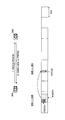
- FIG. 2 is a diagram for explaining HARQ feedback in the side link.
- step 1 the user device 20A transmits the PSCCH / PSCH to the user device 20B, and in step 2, the user device 20B sends the user device 20A a HARQ for the PSCCH / PSCH.
- -ACK is transmitted on the PSFCH.
- PSFCH is transmitted at the last symbol of the slot.
- the resource in the time domain of the PSFCH is a resource associated with the PSCCH / PSSCH and is not dynamically notified.
- the present invention is not limited to the example of FIG.
- the PSFCH may be transmitted with a symbol other than the last symbol of the slot.
- HARQ feedback in sidelink transmission mode 1 In the side link transmission mode 1 in which the PSCCH / PSCH is transmitted from the user device 20A to the user device 20B based on the SL scheduling by the base station device 10, HARQ-ACK is sent from the user device 20A to the base station device 10. Be fed back.
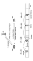
- FIG. 3 is a diagram for explaining HARQ-ACK in the side link transmission mode 1.
- step 1 the SL scheduling is transmitted from the base station apparatus 10 to the user apparatus 20A on the PDCCH, and in step 2, the PSCCH / PSCH based on the SL scheduling is transmitted from the user apparatus 20A to the user. It is transmitted to the device 20B.
- step 3 HARQ-ACK for the PSCCH / PSSCH is transmitted from the user device 20B to the user device 20A on the PSFCH, and in step 4, HARQ-ACK based on the HARQ-ACK is transmitted from the user device 20A to the base station device. It is transmitted on PUCCH / PUSCH to 10.
- the feedback procedure is not limited to this.
- HARQ-ACK for the PSCCH / PSSCH may be transmitted from the user device 20B to the base station device 10 on the PUCCH / PUSCH.
- the base station device 10 in the present invention may be replaced with the user device 20C
- the PUCCH may be replaced with the PSFCH
- the PUSCH may be replaced with the PSSCH.
- DCI Downlink Control Information
- SCI Seglink Control Information
- Problem A There is a problem of how to secure the timing of HARQ feedback from the user device 20A to the base station device 10 in consideration of the transmission of PSFCH from the user device 20B to the user device 20A.
- Problem B HARQ-ACK (SL HARQ-ACK) of the side link between the user device 20A and the user device 20B and HARQ-ACK (Uu HARQ-ACK) between the user device 20A and the base station device.
- HARQ-ACK SL HARQ-ACK
- Uu HARQ-ACK Uu HARQ-ACK
- SL HARQ-ACK may mean HARQ-ACK corresponding to TB (Transport Block) transmission scheduled by the DCI (Downlink Control Information) format (DCI information) that schedules SL transmission.
- DCI Downlink Control Information
- SL HARQ-ACK is an example and may have a different name.
- Uu HARQ-ACK may mean HARQ-ACK corresponding to TB transmission scheduled by the DCI format (eg, DCI format1_0, DCI format1_1) that schedules DL (Downlink) transmission.
- DCI format eg, DCI format1_0, DCI format1_1
- Uu HARQ-ACK is an example and may have a different name.
- the eMBB HARQ-ACK may mean the operation of the UE for the eMBB and / or the HARQ-ACK corresponding to the TB transmission scheduled by the DCI format associated with the low priority.
- slot-based HARQ feedback and non-priority transmission can be mentioned.
- eMBB HARQ-ACK is an example and may have a different name.
- the URLLC HARQ-ACK may mean the operation of the UE for the URLLC and / or the HARQ-ACK corresponding to the TB transmission scheduled by the DCI format associated with the high priority. For example, subslot-based HARQ feedback and priority transmission can be mentioned.
- URLLC HARQ-ACK is an example and may have a different name.
- the following method is used.
- (1) DCI format It is conceivable to use different DCI formats as the above two DCI formats.
- (2) RNTI scrambling DCI (RNTI scrambling DCI) As the above two DCI formats, it is conceivable to scramble using different RNTIs.
- (3) CORESET It is conceivable to assign different CORESETs as the above two DCI formats.
- Search space It is conceivable to allocate different search spaces as the above two DCI formats.
- Priority level It is conceivable to assign different priority levels as the above two DCI formats.
- eMBB and URLLC are intended to indicate different service types, and types other than these service types may be used.
- the HARQ-ACK codebook includes a time domain (for example, a slot), a frequency domain (for example, a component carrier (CC)), a spatial domain (for example, a layer), and a transport block (TB). )), And may be configured to include a bit for HARQ-ACK in at least one unit of a group of code blocks (code block group (CBG)) constituting TB.
- the CC is also called a cell, a serving cell, a carrier, or the like.
- the bit is also referred to as a HARQ-ACK bit, a HARQ-ACK information, a HARQ-ACK information bit, or the like.
- the HARQ-ACK codebook is also called a PDSCH-HARQ-ACK codebook (pdsch-HARQ-ACK-Codebook), a codebook, a HARQ codebook, a HARQ-ACK size, or the like.
- the number of bits (size) and the like included in the HARQ-ACK codebook may be determined quasi-static (semi-static) or dynamically (dynamic).
- the quasi-static HARQ-ACK codebook is also called a Type I HARQ-ACK codebook, a quasi-static codebook, or the like.
- the dynamic HARQ-ACK codebook is also called a Type II HARQ-ACK codebook, a dynamic codebook, or the like.
- Type I HARQ-ACK codebook or the Type II HARQ-ACK codebook may be set in the UE by an upper layer parameter (for example, pdsch-HARQ-ACK-Codebook).
- the UE has a HARQ-ACK bit corresponding to the predetermined range (for example, a range set based on the upper layer parameter) regardless of whether PDSCH is scheduled or not. May be fed back.
- the predetermined range for example, a range set based on the upper layer parameter
- the predetermined range is set or activated in the UE for a predetermined period (for example, a set of a predetermined number of opportunities (occasion) for receiving a candidate PDSCH, or a predetermined number of monitoring opportunities (monitoring occupation) m of the PDCCH). It may be determined based on at least one of the number of CCs, the number of TBs (number of layers or ranks), the number of CBGs per TB, and whether or not spatial bundling is applied.
- the predetermined range is also referred to as a HARQ-ACK bundling window, a HARQ-ACK feedback window, a bundling window, a feedback window, or the like.
- the UE feeds back the NACK bit as long as it is within a predetermined range even if there is no PDSCH scheduling for the UE. Therefore, when using the Type I HARQ-ACK codebook, it is expected that the number of HARQ-ACK bits to be fed back will increase.
- the UE may feed back the HARQ-ACK bit for the scheduled PDSCH within the above predetermined range.
- the UE determines the number of bits of the Type II HARQ-ACK codebook based on a predetermined field in the DCI (for example, a DL allocation index (Downlink Acidincentor (Index) (DAI)) field). May be good.
- the DAI field may be split into a counter DAI (counter DAI (cDAI)) and a total DAI (total DAI (tDAI)).
- the counter DAI may indicate a counter value of downlink transmission (PDSCH, data, TB) scheduled within a predetermined period.
- the counter DAI in the DCI that schedules data within the predetermined period may indicate the number counted first in the frequency domain (eg, CC) in the predetermined period and then in the time domain.
- the total DAI may indicate the total value (total number) of data scheduled within a predetermined period.
- the total DAI in the DCI that schedules data in a predetermined time unit (for example, PDCCH monitoring opportunity) within the predetermined period is up to the predetermined time unit (also referred to as point, timing, etc.) within the predetermined period. It may indicate the total number of scheduled data.
- the UE sets one or more HARQ-ACK bits determined (generated) based on the above Type I or Type II HARQ-ACK codebooks as an uplink control channel (Physical Uplink Control Channel (PUCCH)) and an uplink shared channel. (Physical Uplink Shared Channel (PUSCH)) may be used for transmission.
- PUCCH Physical Uplink Control Channel
- PUSCH Physical Uplink Shared Channel
- the timing to be the target of the problem A of how to secure the timing of HARQ feedback from the user device 20A to the base station device 10 is , PDCCH-to-HARQ feedback timing, PSCCH / PSCH-to-HARQ feedback timing, PSFCH-to-HARQ feedback timing and the like.
- the PDCCH-to-HARQ feedback timing is the timing from the transmission / reception of PDCCH between the base station apparatus 10 and the user apparatus 20A to the HARQ feedback to the base station apparatus 10.
- the PSCCH / PSCH-to-HARQ feedback timing is the timing from the transmission / reception of PSCCH / PSCH between the user device 20A and the user device 20B to the HARQ feedback to the base station device 10.
- the PSFCH-to-HARQ feedback timing is the timing from the transmission / reception of PSFCH between the user device 20B and the user device 10A to the HARQ feedback to the base station device 10.
- FIG. 4 is a diagram for explaining the operation of the wireless communication system in the embodiment.
- the user device 20A notifies the base station device 10 of the gap (time difference) between the PSCCH / PSCH and the PSFCH.
- the gap between the PSCCH / PSCH and the PSFCH is the transmission / reception of the PSCCH / PSCH between the user device 20A and the user device 20B and the transmission / reception of the PSFCH between the user device 20B and the user device 20A. The gap between them.
- the gap between PSCCH / PSCH and PSFCH may be the gap from the beginning or end of the slot containing PSCCH / PSCH to the beginning or end of the slot containing PSCCH / PSCCH /. It may be a gap from the beginning or end symbol of the PSSCH to the beginning or end symbol of the PSFCH.
- the unit of the gap may be a slot unit, a subslot unit, or a symbol unit.
- the following gaps can be considered as the gaps notified to the base station apparatus 10.
- the gap notified to the base station apparatus 10 may be the largest gap among a plurality of gaps between PSCCH / PSCH and PSFCH.
- the gap notified to the base station apparatus 10 may be the period of the slot periodically available for PSFCH.
- the gap may be notified for each of the plurality of resource pools, or the common gap may be notified for all the resource pools.
- the gap may be notified only for the preset resource pool, or the gap is notified for both the preset resource pool and the configured resource pool. May be good.
- the gap notified to the base station apparatus 10 may be an appropriate combination of the gaps described in (1), (2) and (3) above.
- the base station apparatus 10 notifies the user apparatus 10A of the time difference (slot unit / subslot unit / symbol unit) between the PDCCH and the PUCCH / PUSCH. ..
- the time difference notified to the user device 10A may be the time difference between PSCCH / PSSCH and PUCCH / PUSCH.
- the time difference notified to the user device 10A may be the time difference between PSFCH and PUCCH / PUSCH.
- the time difference between PDCCH and PUCCH / PUSCH corresponds to the above-mentioned PDCCH-to-HARQ feedback timing.
- the field name in the DCI format for notifying the time difference between PDCCH and PUCCH / PUSCH may be, for example, PDCCH-to-HARQ feedback timing, or may be another name.
- the time difference between PSCCH / PSCH and PUCCH / PUSCH corresponds to the above-mentioned PSCCH / PSCH-to-HARQ feedback timing.
- the field name in the DCI format for notifying the time difference between PSCCH / PSCH and PUCCH / PUSCH may be, for example, PSCCH / PSCH-to-HARQ feedback timing or another name.
- the time difference between PSFCH and PUCCH / PUSCH corresponds to the above-mentioned PSFCH-to-HARQ feedback timing.
- the field name in the DCI format for notifying the time difference between PSFCH and PUCCH / PUSCH may be, for example, PSFCH-to-HARQ feedback timing or another name.
- the user device 20A schedules the DCI format (eg, the first DCI format) that allocates the PDSCH and instructs feedback (that is, Uu HARQ-ACK) in a certain slot, and SL transmission is scheduled and is in the same slot.
- the DCI format eg, the first DCI format
- a second DCI format that indicates (explicitly or implicitly) the feedback (ie, SL HARQ-ACK). That is, when the first DCI format and the second DCI format instructing Uu HARQ-ACK and SL HARQ-ACK in the same slot as described above are received, it can be considered as an error case.
- the user apparatus 20A may drop or postpone the SL HARQ-ACK.
- Uu HARQ-ACK may be dropped or postponed.
- either SL HARQ-ACK or Uu HARQ-ACK may be dropped or postponed, depending on the implementation of the user device 20A.
- the HARQ-ACK of the link (eg, Uu or SL) corresponding to the earlier scheduling may be dropped or postponed.
- the order of priority may be SL-unicast HARQ-ACK> Uu HARQ-ACK> SL-group cast HARQ-ACK.
- the DCI format that assigns PDSCH and instructs feedback (Uu HARQ-ACK) in a certain slot
- the feedback (SL HARQ-ACK) in the same slot while scheduling SL transmission (explicitly). It is also conceivable to multiplex SL HARQ-ACK and Uu HARQ-ACK when another DCI format instructed (either objectively or implicitly) is received.
- Uu URLLC HARQ-ACK and SL eMBB HARQ-ACK can be treated in the same way as when the same slot is notified as a feedback slot (that is, in the case of Uu and Uu).
- SL eMBB HARQ-ACK may be dropped or postponed
- Uu URLLC HARQ-ACK and SL eMBB HARQ-ACK may be multiplexed and transmitted at different coding rates.
- SL eMBB HARQ-ACK may be dropped or postponed.
- Uu URLLC HARQ-ACK and Uu In the case where the same slot is notified as the feedback slot of Uu URLLC HARQ-ACK and SL URLLC HARQ-ACK (in the case of Uu and SL), which is one example in the task C, Uu URLLC HARQ-ACK and Uu It is conceivable to handle it in the same manner as when the same slot is notified as the feedback slot of URLLC HARQ-ACK (in the case of Uu and Uu). Alternatively, either Uu URLLC HARQ-ACK or SL URLLC HARQ-ACK may be dropped or postponed.
- SL URLLC HARQ-ACK may always be dropped or postponed
- Uu URLLC HARQ-ACK may always be dropped or postponed, or one of them may be dropped or postponed according to the priority. Either one may be dropped or postponed depending on the implementation of the user device 20A.
- both HARQ-ACKs may be transmitted by multiplexing.
- the same slot is notified as a feedback slot for Uu eMBB HARQ-ACK and SL URLLC HARQ-ACK (in the case of eMBB and URLLC)
- it is used as a feedback slot for Uu eMBB HARQ-ACK and SL eMBB HARQ-ACK. It may be treated in the same manner as when the same slot is notified (in the case of eMBB and eMBB).
- SL HARQ-ACK is not distinguished based on the service type / priority level. For example, when the same slot is notified as the feedback slot of Uu eMBB HARQ-ACK and SL HARQ-ACK, regardless of whether SL HARQ-ACK is SL eMBB HARQ-ACK or SL URLLC HARQ-ACK.
- the embodiment corresponding to the subject B may be applied.
- a HARQ-ACK bit corresponding to the DCI transmission that is assumed to be scheduled for SL transmission.
- the DAI is transmitted on the DCI
- the user device 20A is the DCI transmitted (to the user device 20A) to schedule the SL transmission based on the DAI.
- the number of can be estimated.
- the SL transmission is scheduled and received. It is conceivable to generate a HARQ-ACK bit corresponding to the DCI / PDSCH to be obtained. In this embodiment, it may be assumed that the DAI is not transmitted on the scheduling DCI.
- the type of HARQ-ACK codebook for the side link (SL) may be set (in advance). Alternatively, it may be specified in the specifications.
- the same type of HARQ-ACK codebook as Uu is always set. Alternatively, no additional settings other than those of Uu's HARQ-ACK codebook may be required. In this case, when the SL HARQ-ACK codebook is generated, the operation of the user device 20A may be determined by the setting of the HARQ-ACK codebook of Uu.
- a different type of HARQ-ACK codebook from Uu may be set.
- Uu HARQ can be applied to different HARQ-ACK multiplex rules depending on whether the type of HARQ-ACK codebook set for SL and the type of HARQ-ACK codebook set for Uu are the same type.
- -It may be applied to multiplex of ACK and SL HARQ-ACK. For example, when the type of the HARQ-ACK codebook for SL and the type of the HARQ-ACK codebook for Uu are different, the processing of the same embodiment as that of the embodiment corresponding to the task B is applied (for example,).
- the type of the HARQ-ACK codebook for SL and the type of the HARQ-ACK codebook for Uu are different, one of the HARQ-ACK codebook types may be followed (for example, Uu may be followed). And you may follow SL).
- either the PUCCH containing SL HARQ-ACK and the PUCCH containing other uplink control types such as CSI / SR may be dropped or postponed.
- a PUCCH containing SL HARQ-ACK may be transmitted and a PUCCH containing other uplink control types such as CSI / SR may be dropped or postponed.
- a rule for handling a collision between PUCCH including SL HARQ-ACK and PUCCH including other uplink control types such as SL CSI / SR (SL CSI / SR rule) and SL HARQ-ACK are included.
- the rule for handling the collision between the PUCCH and the PUCCH including other uplink control types such as Uu's CSI / SR (Uu CSI / SR rule) may be different rules.
- the user device 20A can appropriately transmit the SL HARQ-ACK to the base station device 10.
- the user apparatus 20A can execute HARQ feedback in consideration of the SL transmission timing and the processing time.
- the user device 20A can maintain the performance of the Uu HARQ-ACK feedback.
- the user device 20A may consider the performance of URLLC.
- the user apparatus 20A can prevent a discrepancy (difference in recognition) with the base station apparatus 10 in terms of the payload size (payload size) of HARQ-ACK.
- the base station apparatus 10 and the user apparatus 20 include a function of carrying out the above-described embodiment.
- the base station apparatus 10 and the user apparatus 20 may each have only a part of the functions in the embodiment.
- FIG. 5 is a diagram showing an example of the functional configuration of the base station device 10.
- the base station apparatus 10 includes a transmission unit 110, a reception unit 120, a setting unit 130, and a control unit 140.
- the functional configuration shown in FIG. 5 is only an example. Any function classification and name of the functional unit may be used as long as the operation according to the embodiment of the present invention can be executed.
- the transmission unit 110 includes a function of generating a signal to be transmitted to the user device 20 side and transmitting the signal wirelessly. Further, the transmission unit 110 transmits information such as SL scheduling to the user device 20.
- the receiving unit 120 includes a function of receiving various signals transmitted from the user apparatus 20 and acquiring information of, for example, a higher layer from the received signals.
- the setting unit 130 stores preset setting information and various setting information to be transmitted to the user device 20 in the storage device, and reads the setting information from the storage device as needed.
- the content of the setting information is, for example, information related to the setting of V2X.
- control unit 140 performs processing related to the setting for the user device 20 to perform V2X. Further, the function unit related to signal transmission in the control unit 140 may be included in the transmission unit 110, and the function unit related to signal reception in the control unit 140 may be included in the reception unit 120.
- FIG. 6 is a diagram showing an example of the functional configuration of the user device 20.
- the user device 20 includes a transmission unit 210, a reception unit 220, a setting unit 230, and a control unit 240.
- the functional configuration shown in FIG. 6 is only an example. Any function classification and name of the functional unit may be used as long as the operation according to the embodiment of the present invention can be executed.
- the transmission unit 210 creates a transmission signal from the transmission data and wirelessly transmits the transmission signal.
- the receiving unit 220 wirelessly receives various signals and acquires a signal of a higher layer from the received signal of the physical layer. Further, the receiving unit 220 has a function of receiving the SL scheduling transmitted from the base station apparatus 10.
- the setting unit 230 stores various setting information received from the base station device 10 or the user device 20 by the receiving unit 220 in the storage device, and reads it out from the storage device as needed.
- the setting unit 230 also stores preset setting information.
- the content of the setting information is, for example, information related to V2X and HARQ processing.
- the control unit 240 controls the D2D communication executed with the other user device 20 as described in the embodiment. In addition, the control unit 240 executes V2X and HARQ processing.
- the function unit related to signal transmission in the control unit 240 may be included in the transmission unit 210, and the function unit related to signal reception in the control unit 240 may be included in the reception unit 220.
- each functional block may be realized by one device in which a plurality of elements are physically and / or logically combined, or two or more devices physically and / or logically separated from each other directly and. / Or indirectly (eg, wired and / or wireless) may be connected and realized by these plurality of devices.
- both the base station device 10 and the user device 20 in the embodiment of the present invention may function as a computer that performs the processing according to the embodiment of the present invention.
- FIG. 7 is a diagram showing an example of the hardware configuration of the wireless communication device which is the base station device 10 or the user device 20 according to the embodiment of the present invention.
- the above-mentioned base station device 10 and user device 20 are physically as computer devices including a processor 1001, a storage device 1002, an auxiliary storage device 1003, a communication device 1004, an input device 1005, an output device 1006, a bus 1007, and the like. It may be configured.
- the word “device” can be read as a circuit, device, unit, etc.
- the hardware configuration of the base station device 10 and the user device 20 may be configured to include one or more of the devices shown by 1001 to 1006 shown in the figure, or may be configured without including some of the devices. May be done.
- the processor 1001 For each function of the base station device 10 and the user device 20, by loading predetermined software (program) on the hardware such as the processor 1001 and the storage device 1002, the processor 1001 performs an calculation and the communication device 1004 communicates. It is realized by controlling the reading and / or writing of data in the storage device 1002 and the auxiliary storage device 1003.
- the processor 1001 operates, for example, an operating system to control the entire computer.
- the processor 1001 may be composed of a central processing unit (CPU: Central Processing Unit) including an interface with a peripheral device, a control device, an arithmetic unit, a register, and the like.
- CPU Central Processing Unit
- the processor 1001 reads a program (program code), a software module or data from the auxiliary storage device 1003 and / or the communication device 1004 into the storage device 1002, and executes various processes according to these.
- a program program code
- the program a program that causes a computer to execute at least a part of the operations described in the above-described embodiment is used.
- the transmission unit 110, the reception unit 120, the setting unit 130, and the control unit 140 of the base station device 10 shown in FIG. 5 may be stored in the storage device 1002 and realized by a control program that operates in the processor 1001.
- processor 1001. are stored in the storage device 1002 and realized by a control program that operates in the processor 1001. May be good. Although it has been described that the various processes described above are executed by one processor 1001, they may be executed simultaneously or sequentially by two or more processors 1001. Processor 1001 may be mounted on one or more chips. The program may be transmitted from the network via a telecommunication line.
- the storage device 1002 is a computer-readable recording medium, and is, for example, at least one such as a ROM (Read Only Memory), an EPROM (Erasable Programmable ROM), an EEPROM (Electrically Erasable Programmable ROM), and a RAM (Random Access Memory). It may be configured.
- the storage device 1002 may be referred to as a register, a cache, a main memory (main storage device), or the like.
- the storage device 1002 can store a program (program code), a software module, or the like that can be executed to carry out the process according to the embodiment of the present invention.
- the auxiliary storage device 1003 is a computer-readable recording medium, and is, for example, an optical disk such as a CD-ROM (Compact Disc ROM), a hard disk drive, a flexible disk, an optical magnetic disk (for example, a compact disk, a digital versatile disk, Blu).
- -It may be composed of at least one of a ray (registered trademark) disk), a smart card, a flash memory (for example, a card, a stick, a key drive), a floppy (registered trademark) disk, a magnetic strip, and the like.
- the auxiliary storage device 1003 may be referred to as an auxiliary storage device.
- the storage medium described above may be, for example, a database, server or other suitable medium containing the storage device 1002 and / or the auxiliary storage device 1003.
- the communication device 1004 is hardware (transmission / reception device) for communicating between computers via a wired and / or wireless network, and is also referred to as, for example, a network device, a network controller, a network card, a communication module, or the like.
- the transmission unit 110 and the reception unit 120 of the base station device 10 may be realized by the communication device 1004.
- the transmission unit 210 and the reception unit 220 of the user device 20 may be realized by the communication device 1004.
- the input device 1005 is an input device (for example, a keyboard, a mouse, a microphone, a switch, a button, a sensor, etc.) that receives an input from the outside.
- the output device 1006 is an output device (for example, a display, a speaker, an LED lamp, etc.) that outputs to the outside.
- the input device 1005 and the output device 1006 may have an integrated configuration (for example, a touch panel).
- Bus 1007 may be composed of a single bus, or may be composed of different buses between devices.
- the base station device 10 and the user device 20 are a microprocessor, a digital signal processor (DSP: Digital Signal Processor), an ASIC (Application Specific Integrated Circuit), a PLD (Programmable Logic Device), an FPGA (Field Programmable Gate Array), etc., respectively. It may be configured to include the above hardware, and a part or all of each functional block may be realized by the hardware. For example, processor 1001 may be implemented on at least one of these hardware.
- the transmission unit that transmits the side link data based on the side link scheduling information received from the base station apparatus and the user who has received the side link data.
- a receiving unit that receives feedback information for the side link data from the device is provided, and the transmitting unit includes first HARQ-ACK information based on the feedback information and data received by the receiving unit from the base station device.
- a user apparatus is provided that transmits a second HARQ-ACK information to the base station apparatus based on a predetermined assumption.
- the above configuration provides a technique for defining how to feed back HARQ-ACK in direct terminal-to-terminal communication scheduled by the base station apparatus.
- the operation of the plurality of functional units may be physically performed by one component, or the operation of one functional unit may be physically performed by a plurality of components.
- the order of processing may be changed as long as there is no contradiction.
- the base station device 10 and the user device 20 have been described with reference to functional block diagrams, but such devices may be implemented in hardware, software, or a combination thereof.
- the software operated by the processor of the base station apparatus 10 according to the embodiment of the present invention and the software operated by the processor of the user apparatus 20 according to the embodiment of the present invention are random access memory (RAM), flash memory, and read, respectively. It may be stored in a dedicated memory (ROM), EPROM, EEPROM, registers, hard disk (HDD), removable disk, CD-ROM, database, server or any other suitable storage medium.
- information notification includes physical layer signaling (for example, DCI (Downlink Control Information), UCI (Uplink Control Information)), higher layer signaling (for example, RRC (Radio Resource Control) signaling, MAC (Medium Access Control) signaling, etc. Broadcast information (MIB (Master Information Block), SIB (System Information Block)), other signals, or a combination thereof may be used.
- RRC signaling may be referred to as an RRC message, for example, RRC. It may be a connection setup (RRCConnectionSetup) message, an RRC connection reconfiguration (RRCConnectionReconfiguration) message, or the like.
- Each aspect / embodiment described in the present specification includes LTE (LongTermEvolution), LTE-A (LTE-Advanced), SUPER 3G, IMT-Advanced, 4G, 5G, FRA (FutureRadioAccess), W-CDMA. (Registered Trademarks), GSM (Registered Trademarks), CDMA2000, UMB (Ultra-Mobile Broadband), IEEE 802.11 (Wi-Fi), IEEE 802.16 (WiMAX), LTE 802.20, UWB (Ultra-WideBand) It may be applied to systems utilizing Bluetooth®, other suitable systems and / or next-generation systems extended based on them.
- the specific operation performed by the base station apparatus 10 in the present specification may be performed by its upper node (upper node).
- various operations performed for communication with the user device 20 are other than the base station device 10 and / or the base station device 10. It is clear that it can be done by other network nodes, such as, but not limited to, MME or S-GW.
- MME Mobility Management Entity
- S-GW Serving Mobility Management Entity
- the user device 20 may be a subscriber station, a mobile unit, a subscriber unit, a wireless unit, a remote unit, a mobile device, a wireless device, a wireless communication device, a remote device, a mobile subscriber station, an access terminal, a mobile terminal, etc. It may also be referred to as a wireless terminal, remote terminal, handset, user agent, mobile client, client, or some other suitable term.
- the base station apparatus 10 may be referred to by those skilled in the art by NB (NodeB), eNB (evolvedNodeB), gNB, BaseStation, or some other suitable term.
- NB NodeB
- eNB evolvedNodeB
- gNB BaseStation
- determining and “determining” used in this specification may include a wide variety of actions.
- "Judgment” and “decision” are, for example, judgment (judging), calculation (calculating), calculation (computing), processing (processing), derivation (deriving), investigating (investigating), searching (looking up) (for example, table , Searching in a database or another data structure), confirming (ascertaining) may be regarded as “judgment” or “decision”.
- judgment and “decision” are receiving (for example, receiving information), transmitting (for example, transmitting information), input (input), output (output), and access.
- (Accessing) for example, accessing data in memory) may be regarded as "judgment” or “decision”.
- judgment and “decision” mean that “resolving”, “selecting”, “choosing”, “establishing”, “comparing”, etc. are regarded as “judgment” and “decision”. Can include. That is, “judgment” and “decision” may include that some action is regarded as “judgment” and “decision”.
- Base station device 110 Transmission unit 120 Reception unit 130 Setting unit 140 Control unit 20 User device 210 Transmission unit 220 Reception unit 230 Setting unit 240 Control unit 1001 Processor 1002 Storage device 1003 Auxiliary storage device 1004 Communication device 1005 Input device 1006 Output device
Landscapes
- Engineering & Computer Science (AREA)
- Computer Networks & Wireless Communication (AREA)
- Signal Processing (AREA)
- Mobile Radio Communication Systems (AREA)
Priority Applications (5)
| Application Number | Priority Date | Filing Date | Title |
|---|---|---|---|
| CN201980097173.0A CN113924802A (zh) | 2019-06-11 | 2019-06-11 | 用户装置 |
| JP2021525461A JP7344963B2 (ja) | 2019-06-11 | 2019-06-11 | 端末、基地局、通信システム、及び通信方法 |
| EP19932729.7A EP3986020B1 (en) | 2019-06-11 | 2019-06-11 | User equipment |
| US17/596,251 US12028170B2 (en) | 2019-06-11 | 2019-06-11 | Terminal, base station and method |
| PCT/JP2019/023173 WO2020250325A1 (ja) | 2019-06-11 | 2019-06-11 | ユーザ装置 |
Applications Claiming Priority (1)
| Application Number | Priority Date | Filing Date | Title |
|---|---|---|---|
| PCT/JP2019/023173 WO2020250325A1 (ja) | 2019-06-11 | 2019-06-11 | ユーザ装置 |
Publications (1)
| Publication Number | Publication Date |
|---|---|
| WO2020250325A1 true WO2020250325A1 (ja) | 2020-12-17 |
Family
ID=73782101
Family Applications (1)
| Application Number | Title | Priority Date | Filing Date |
|---|---|---|---|
| PCT/JP2019/023173 Ceased WO2020250325A1 (ja) | 2019-06-11 | 2019-06-11 | ユーザ装置 |
Country Status (5)
| Country | Link |
|---|---|
| US (1) | US12028170B2 (https=) |
| EP (1) | EP3986020B1 (https=) |
| JP (1) | JP7344963B2 (https=) |
| CN (1) | CN113924802A (https=) |
| WO (1) | WO2020250325A1 (https=) |
Cited By (2)
| Publication number | Priority date | Publication date | Assignee | Title |
|---|---|---|---|---|
| US20220123905A1 (en) * | 2019-07-05 | 2022-04-21 | Guangdong Oppo Mobile Telecommunications Corp., Ltd. | Method and device for feeding back sidelink transmission state |
| WO2024057551A1 (ja) * | 2022-09-16 | 2024-03-21 | 株式会社Nttドコモ | 端末及び通信方法 |
Families Citing this family (14)
| Publication number | Priority date | Publication date | Assignee | Title |
|---|---|---|---|---|
| WO2020261350A1 (ja) * | 2019-06-24 | 2020-12-30 | 株式会社Nttドコモ | 端末及び通信方法 |
| CN112152760B (zh) * | 2019-06-27 | 2022-03-29 | 华为技术有限公司 | 一种psfch的发送方法及装置 |
| US10938733B2 (en) * | 2019-07-19 | 2021-03-02 | Lenovo (Singapore) Pte. Ltd. | Transmitting data using a relay user equipment |
| WO2020113241A2 (en) * | 2019-07-25 | 2020-06-04 | Futurewei Technologies, Inc. | Transmission beam control in wireless communication systems |
| KR102894787B1 (ko) * | 2019-08-06 | 2025-12-03 | 주식회사 아이티엘 | 무선통신시스템에서 harq 타이밍을 결정하는 방법 및 장치 |
| CN110536448A (zh) * | 2019-08-15 | 2019-12-03 | 中兴通讯股份有限公司 | 一种信息确定方法、装置和存储介质 |
| AU2020335057B2 (en) * | 2019-08-28 | 2025-05-01 | Guangdong Oppo Mobile Telecommunications Corp., Ltd. | User equipment and method of resource transmission |
| KR102783103B1 (ko) * | 2019-09-30 | 2025-03-17 | 후아웨이 테크놀러지 컴퍼니 리미티드 | 피드백 정보 전송 방법 및 장치 |
| KR102913257B1 (ko) * | 2019-10-07 | 2026-01-15 | 엘지전자 주식회사 | Nr v2x에서 psfch 자원을 선택하는 방법 및 장치 |
| US12184433B2 (en) * | 2019-10-25 | 2024-12-31 | Qualcomm Incorporated | Hybrid automatic repeat request (HARQ) codebook enhancement and physical uplink control channel (PUCCH) resource determination with sidelink feedback forwarding |
| KR102840432B1 (ko) * | 2020-04-28 | 2025-07-29 | 삼성전자주식회사 | 무선 통신 시스템에서 단말의 송신 전력 제어 방법 및 장치 |
| WO2022030525A1 (en) * | 2020-08-05 | 2022-02-10 | Sharp Kabushiki Kaisha | Code rate determination for multiplexing of harq-ack with different priorities on pucch with separate coding |
| CN116368912A (zh) * | 2021-04-14 | 2023-06-30 | Lg 电子株式会社 | 在无线通信系统中发送或接收物理侧链路反馈信道的方法和设备 |
| WO2024173210A1 (en) * | 2023-02-14 | 2024-08-22 | Interdigital Patent Holdings, Inc. | Harq sub-codebook generation |
Family Cites Families (13)
| Publication number | Priority date | Publication date | Assignee | Title |
|---|---|---|---|---|
| HUE043320T2 (hu) * | 2015-02-26 | 2019-08-28 | Intel Ip Corp | Rendszerek, eljárások és eszközök rádiós elérési technológia koordinációjához |
| WO2017017871A1 (ja) * | 2015-07-29 | 2017-02-02 | 日本電気株式会社 | 端末及び基地局並びにこれらの方法 |
| WO2017083388A1 (en) * | 2015-11-10 | 2017-05-18 | Idac Holdings, Inc. | Methods and apparatuses directed to cooperative communications |
| US10334586B2 (en) * | 2016-01-22 | 2019-06-25 | Qualcomm Incorporated | Hybrid automatic repeat request feedback for unicast sidelink communications |
| US20190174530A1 (en) * | 2016-07-01 | 2019-06-06 | Lg Electronics Inc. | Method for transmitting and receiving data in wireless communication system and apparatus therefor |
| US10939417B2 (en) * | 2016-08-24 | 2021-03-02 | Lg Electronics Inc. | Method and device for transmitting and receiving PSCCH and PSSCH by terminal in wireless communication system |
| CN107889073B (zh) * | 2016-09-30 | 2022-05-24 | 北京三星通信技术研究有限公司 | 一种v2x通信中的发送资源确定方法和设备 |
| US10931426B2 (en) * | 2017-08-10 | 2021-02-23 | Futurewei Technologies, Inc. | System and method for sidelink feedback |
| JP7229362B2 (ja) * | 2018-12-29 | 2023-02-27 | 北京小米移動軟件有限公司 | 直接通信のデータ伝送方法、装置及びシステム |
| CN111431674B (zh) * | 2019-01-10 | 2024-09-06 | 夏普株式会社 | 由用户设备执行的方法以及用户设备 |
| US11929830B2 (en) * | 2019-01-21 | 2024-03-12 | Lg Electronics Inc. | Method for transmitting sidelink HARQ feedback in wireless communication system |
| CN110535555B (zh) * | 2019-03-28 | 2023-05-23 | 中兴通讯股份有限公司 | 一种确定传输优先级的方法、装置和计算机可读存储介质 |
| KR102868523B1 (ko) * | 2019-04-01 | 2025-10-13 | 삼성전자 주식회사 | 무선 통신 시스템에서 비승인 기반 데이터 전송 방법 및 장치 |
-
2019
- 2019-06-11 US US17/596,251 patent/US12028170B2/en active Active
- 2019-06-11 CN CN201980097173.0A patent/CN113924802A/zh active Pending
- 2019-06-11 WO PCT/JP2019/023173 patent/WO2020250325A1/ja not_active Ceased
- 2019-06-11 EP EP19932729.7A patent/EP3986020B1/en active Active
- 2019-06-11 JP JP2021525461A patent/JP7344963B2/ja active Active
Non-Patent Citations (9)
| Title |
|---|
| 3GPP TS 36.213, June 2017 (2017-06-01) |
| CATT: "On Mode 1 resource allocation in NR V2X", 3GPP TSG RAN WG1 #97 R1-1906315, 17 May 2019 (2019-05-17), XP051708350 * |
| ERICSSON: "Feature lead summary #5 on Resource allocation for NR sidelink Mode 1", 3GPP TSG RAN WG1 #97 R1-1907947, 17 May 2019 (2019-05-17), XP051740205 * |
| FUJITSU: "Discussion on HARQ-ACK feedback for NR- V2X", 3GPP TSG RAN WG1 #96 R1-1901944, 1 March 2019 (2019-03-01), XP051599638 * |
| HUAWEI; HISILICON: "Design and contents of PSCCH and PSFCH", 3GPP TSG RAN WG1 #97 R1- 1906596, 17 May 2019 (2019-05-17), XP051708632 * |
| NTT DOCOMO; INC: "NR Sidelink Resource Allocation Mechanism Mode 1", 3GPP TSG RAN WG1 #97 R1- 1906206, 17 May 2019 (2019-05-17), XP051708245 * |
| NTT DOCOMO; INC: "NR Sidelink Resource Allocation Mechanism Mode 1", 3GPP TSG RAN WG1 #98 R1-1909186, 17 August 2019 (2019-08-17), XP051765791 * |
| See also references of EP3986020A4 |
| VIVO: "Physical layer procedure for NR sidelink", 3GPP TSG RAN WG1 #95 R1- 1812307, 16 November 2018 (2018-11-16), XP051478496 * |
Cited By (4)
| Publication number | Priority date | Publication date | Assignee | Title |
|---|---|---|---|---|
| US20220123905A1 (en) * | 2019-07-05 | 2022-04-21 | Guangdong Oppo Mobile Telecommunications Corp., Ltd. | Method and device for feeding back sidelink transmission state |
| US12452021B2 (en) * | 2019-07-05 | 2025-10-21 | Guangdong Oppo Mobile Telecommunications Corp., Ltd. | Method and device for feeding back sidelink transmission state |
| WO2024057551A1 (ja) * | 2022-09-16 | 2024-03-21 | 株式会社Nttドコモ | 端末及び通信方法 |
| JPWO2024057551A1 (https=) * | 2022-09-16 | 2024-03-21 |
Also Published As
| Publication number | Publication date |
|---|---|
| JP7344963B2 (ja) | 2023-09-14 |
| JPWO2020250325A1 (https=) | 2020-12-17 |
| EP3986020B1 (en) | 2025-08-06 |
| CN113924802A (zh) | 2022-01-11 |
| EP3986020A4 (en) | 2022-12-07 |
| US12028170B2 (en) | 2024-07-02 |
| EP3986020A1 (en) | 2022-04-20 |
| US20220321278A1 (en) | 2022-10-06 |
Similar Documents
| Publication | Publication Date | Title |
|---|---|---|
| JP7344963B2 (ja) | 端末、基地局、通信システム、及び通信方法 | |
| JP7300502B2 (ja) | 端末、通信方法、及び基地局 | |
| CN113196856B (zh) | 通信装置及通信方法 | |
| US11963135B2 (en) | User equipment, base station, and method of transmitting a scheduling request | |
| JP7075344B2 (ja) | 端末、システム、及び送信方法 | |
| EP3989658A1 (en) | Terminal and communication method | |
| EP3499992A1 (en) | User apparatus and communication method | |
| CN107926009A (zh) | 用户装置及通信方法 | |
| JPWO2020144787A1 (ja) | ユーザ装置、及びフィードバック情報送信方法 | |
| WO2022070284A1 (ja) | 端末、及びリソース制御方法 | |
| JP6786485B2 (ja) | ユーザ装置、基地局及び通信方法 | |
| EP4429348A1 (en) | Terminal and communication method | |
| EP4489490A1 (en) | Terminal and communication method | |
| WO2020230213A1 (ja) | ユーザ装置 | |
| WO2021095254A1 (ja) | 端末及び通信方法 | |
| EP4333525A1 (en) | Communication device, base station, and communication method | |
| US20250024455A1 (en) | Terminal and communication method | |
| EP4418779A1 (en) | Terminal and communication method | |
| EP4415442A1 (en) | Terminal and communication method | |
| EP4024980A1 (en) | Terminal and communication method | |
| EP4432747A1 (en) | Terminal and communication method | |
| US20250227691A1 (en) | Terminal and communication method | |
| EP4426047A1 (en) | Terminal and communication method | |
| EP4426046A1 (en) | Terminal and communication method | |
| EP4415443A1 (en) | Terminal and communication method |
Legal Events
| Date | Code | Title | Description |
|---|---|---|---|
| 121 | Ep: the epo has been informed by wipo that ep was designated in this application |
Ref document number: 19932729 Country of ref document: EP Kind code of ref document: A1 |
|
| ENP | Entry into the national phase |
Ref document number: 2021525461 Country of ref document: JP Kind code of ref document: A |
|
| NENP | Non-entry into the national phase |
Ref country code: DE |
|
| ENP | Entry into the national phase |
Ref document number: 2019932729 Country of ref document: EP Effective date: 20220111 |
|
| WWG | Wipo information: grant in national office |
Ref document number: 2019932729 Country of ref document: EP |