WO2020250272A1 - 計測装置 - Google Patents
計測装置 Download PDFInfo
- Publication number
- WO2020250272A1 WO2020250272A1 PCT/JP2019/022927 JP2019022927W WO2020250272A1 WO 2020250272 A1 WO2020250272 A1 WO 2020250272A1 JP 2019022927 W JP2019022927 W JP 2019022927W WO 2020250272 A1 WO2020250272 A1 WO 2020250272A1
- Authority
- WO
- WIPO (PCT)
- Prior art keywords
- light
- interference light
- wavelength
- measuring device
- bandpass filter
- Prior art date
- Legal status (The legal status is an assumption and is not a legal conclusion. Google has not performed a legal analysis and makes no representation as to the accuracy of the status listed.)
- Ceased
Links
Images

Classifications
-
- A—HUMAN NECESSITIES
- A61—MEDICAL OR VETERINARY SCIENCE; HYGIENE
- A61B—DIAGNOSIS; SURGERY; IDENTIFICATION
- A61B3/00—Apparatus for testing the eyes; Instruments for examining the eyes
- A61B3/10—Objective types, i.e. instruments for examining the eyes independent of the patients' perceptions or reactions
- A61B3/102—Objective types, i.e. instruments for examining the eyes independent of the patients' perceptions or reactions for optical coherence tomography [OCT]
-
- G—PHYSICS
- G01—MEASURING; TESTING
- G01N—INVESTIGATING OR ANALYSING MATERIALS BY DETERMINING THEIR CHEMICAL OR PHYSICAL PROPERTIES
- G01N21/00—Investigating or analysing materials by the use of optical means, i.e. using sub-millimetre waves, infrared, visible or ultraviolet light
- G01N21/17—Systems in which incident light is modified in accordance with the properties of the material investigated
Definitions
- the present invention relates to a measuring device.
- An optical interference tomographic device using a wavelength sweep light source is known as an image pickup device for the fundus and the like.
- the wavelength sweep light source has a complicated structure.
- the measuring device of the present disclosure technology is a light source that emits broadband light, and an interference unit that divides the broadband light into measurement light and reference light and generates interference light between the measurement light reflected by an object and the reference light.
- a sweeping unit that sweeps the wavelength of the interference light and a detection unit that detects the interference light output from the sweeping unit are provided.
- the measuring device is an optical coherence tomography (OTC) that acquires a tomographic image of an object.
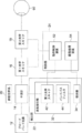
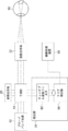
- FIG. 1 shows a block diagram of the measuring device according to the first embodiment. As shown in FIG. 1, the measuring device includes a broadband light source 12 that simultaneously generates coherent light (broadband light) having a plurality of different wavelengths.
- the measuring device includes an interferometer 14 and a reference optical system 20.
- the interferometer 14 divides the light from the broadband light source 12 into a measurement light and a reference light, emits the measurement light to the eye 60 side to be inspected, and emits the reference light to the reference optical system 20 side.
- the reference optical system 20 is composed of a movable mirror or the like, and the optical path length of the reference light can be changed by driving the mirror.
- the reference light reflected by the mirror returns to the interferometer 14.
- the measuring device includes a first optical scanner 16 that scans the measurement light in the horizontal direction in the eye 60 to be inspected, and a second optical scanner 18 that scans the measurement light in the vertical direction in the eye 60 to be inspected. ..
- the measurement light scanned by the first optical scanner 16 and the second optical scanner 18 in the eye 60 to be inspected is reflected by the fundus of the eye 60 to be inspected, and is reflected by the fundus of the eye 60, and the interferometer 14 is transmitted through the second optical scanner 18 and the first optical scanner 16.
- the interferometer 14 interferes with the reference light from the reference optical system 20 and the measurement light reflected by the fundus of the eye 60 to be inspected, and emits the light as interference light.
- the measuring device includes a detection unit 22 and a control unit 24.
- the detection unit 22 has a third optical scanner 42 and a bandpass filter 44, and includes a wavelength sweeping unit 32 that sweeps the interference light and a detector 34 that detects the swept interference light.
- the wavelength sweeping unit 32 sweeps the wavelength of the interference light, which is broadband light, and outputs the interference light having a different wavelength for each time.
- the control unit 24 includes an operation control device 52 that controls the operations of the first optical scanner 16, the second optical scanner 18, and the third optical scanner 42.
- the control unit 24 receives an input of a signal indicating the operation timing of the third optical scanner 42 by the operation control device 52, and based on the input signal, determines the intensity of the swept interference light detected by the detector 34. Based on this, an image processing device 54 that generates a tomographic image of the eye 60 to be inspected is provided.
- the third optical scanner 42 of the wavelength sweeping unit 32 scans the interference light toward the incident surface of the bandpass filter 44.
- Interference light is scanned by the third optical scanner 42 on the incident surface, which is the plane of the bandpass filter 44, on the bandpass filter 44. Therefore, the interference light is irradiated on the incident surface so that the incident angle is different for each time.
- the wavelength of the bandpass filter 44 to pass differs depending on the incident angle. That is, in synchronization with the scanning timing of the third optical scanner 42, the bandpass filter 44 outputs light having a different wavelength for each time.
- the bandpass filter 44 is composed of a multilayer film having a uniform structure in a region (a region scanned by the third optical scanner 42) through which interference light is irradiated.
- the bandpass filter 44 is composed of a dielectric multilayer film, and each film is composed of the same film quality and the same thickness in each portion of the region through which the interference light is irradiated.
- the bandpass filter 44 is composed of a multilayer film having a uniform structure in the region where the interference light is irradiated and passes through, the distance through which the interference light passes through the bandpass filter 44 depends on the incident angle of the interference light. Changes, and the wavelength of the interfering light passing through is different.
- the bandpass filter 44 is configured so that the wavelength of the interfering light passing through differs depending on the incident angle, the interfering light is wavelength-swept in synchronization with the scanning cycle of the third optical scanner 42.
- bandpass filter 44 for example, a TS laser cleanup filter (model number: # 68-855) manufactured by Edmond Optics can be used.
- the range of wavelengths to be swept can be adjusted by adjusting the material and structure of the multilayer film (layer thickness, composition, etc. of each layer).
- the first optical scanner 16, the second optical scanner 18, and the third optical scanner 42 a polygon mirror, a galvano mirror, a resonant scanner, a MEMS scanner, or the like can be adopted.
- the frequency at which the interference light is scanned by the third optical scanner 42 is higher than the frequency at which the first optical scanner 16 and the second optical scanner 18 scan the irradiation light.
- the first optical scanner 16 is set to scan the irradiation light at 10 Hz
- the second optical scanner 18 is set to scan the irradiation light at 100 Hz
- the third optical scanner 42 is set to scan at 50,000 Hz (50 kHz).
- the first optical scanner and the second optical scanner may be driven at the same frequency (10 Hz, 100 Hz, etc.).
- the third optical scanner 42 can change the range in which the interference light is scanned. Specifically, the scanning range is changed by changing the swing width of the third optical scanner 42. More specifically, when the swing width is changed, the angle range of the interference light incident on the bandpass filter 44 changes, so that the wavelength scanning range changes. In this case, when the swing width is large, the wavelength scanning range is expanded, and conversely, when the swing width is small, the wavelength scanning range is reduced.
- a galvanometer mirror or a MEMS (Micro Electro Mechanical System) scanner is adopted as the third optical scanner 42
- the third optical scanner 42 can change the range in which the interference light is scanned. Specifically, the scanning range is changed by changing the swing width of the third optical scanner 42. More specifically, when the swing width is changed, the angle range of the interference light incident on the bandpass filter 44 changes, so that the wavelength scanning range changes. In this case, when the swing width is large, the wavelength scanning range is expanded, and conversely, when the swing width is small, the wavelength scanning range is reduced.
- the configuration of the wavelength sweeping unit 32 is not particularly limited as long as it changes the wavelength to be extracted with time, such as a Fabry-Perot spectroscope or an AOTF (acousto-optic tunable filter). ..
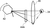
- a polygon mirror is used as the third optical scanner 42.
- the scanned interference light is incident on the bandpass filter 44A at a different incident angle for each time, and differs depending on the incident angle.
- Interference light of wavelength is emitted from the bandpass filter 44A.
- the wavelength sweep unit 32 includes an optical system 46 that guides the interference light that has passed through the bandpass filter 44A to one point of the detection unit of the detector 34.
- the detector 34 is a detector of a type that detects the interference light at the point.
- a point detector photodiode or the like (point sensor)
- point sensor point sensor
- the optical system 46 may be omitted.
- the detector 34 can employ a detector of a type that detects the interference light with a line or a surface.
- the broadband light source 12 simultaneously generates a plurality of coherent lights having different wavelengths.
- the light generated by the broadband light source 12 is divided into irradiation light and reference light by the interferometer 14.
- the optical path length of the reference light is changed by the reference optical system 20, and the light returns to the interferometer 14.
- the irradiation light is scanned in the fundus of the eye 60 to be scanned in the horizontal direction and the vertical direction by the first optical scanner 16 and the second optical scanner 18, respectively, which are controlled by the motion control device 52.
- the reflected light reflected by the fundus of the eye 60 to be inspected returns to the interferometer 14 via the second optical scanner 18 and the first optical scanner 16.
- the reference light from the reference optical system 20 and the reflected light reflected by the fundus of the eye 60 to be inspected are combined by the interference meter 14 and emitted as interference light to the wavelength sweeping unit 32 of the detection unit 22.
- the third optical scanner 42 (polygon mirror (see FIG. 2A)) of the wavelength sweeping unit 32 is controlled by the motion control device 52, and scans the interference light on the incident surface of the bandpass filter 44A.
- the bandpass filter 44A By scanning the interference light on the incident surface of the bandpass filter 44A by the third optical scanner 42, the bandpass filter 44A is irradiated with the interference light so that the incident angle differs with time, and the bandpass filter 44A emits the interference light. , Interference light of different wavelengths is emitted every time.
- Interference light having a different wavelength for each time passed through the bandpass filter 44A is guided to the detector 34 by the optical system 46.
- the frequency at which the interference light is scanned by the third optical scanner 42 is higher than the frequency at which the first optical scanner 16 and the second optical scanner 18 scan the irradiation light in the vertical direction in the eye 60 to be inspected. Therefore, it is possible to acquire information in the thickness direction of each point of the retina of the fundus of the eye to be inspected 60 scanned by the first optical scanner 16 and the second optical scanner 18.
- the third optical scanner 42 of the wavelength sweeping unit 32 is controlled by the operation control device 52.
- Information on the observation position for each time acquired from the first optical scanner 16 and the second optical scanner 18 and a signal indicating the operation timing of the third optical scanner 42 are input to the image processing device 54 from the operation control device 52. Will be done.
- the image processing device 54 determines the rotation angle of the polygon mirror of the third optical scanner 42 for each time, the angle of the reflection mirror of the polygon mirror for each time, based on the signal indicating the operation timing of the third optical scanner 42.
- the angle of incidence of the interference light scanned by the reflection mirror for each time can be known. Therefore, the image processing device 54 knows the wavelength of the interference light detected by the detector 34 for each time, and knows which wavelength the intensity of the interference light detected by the detector 34 is.
- the angle of incidence of the interference light on the bandpass filter 44 changes as the polygon mirror rotates.
- the wavelength sweep light source swept source, hereinafter referred to as SS light source
- the amount of wavelength change with time is constant.
- the image processing device 54 performs signal processing using a delay filter or the like so that the output of the detector 34 whose wavelength change amount with time is not constant is constant with the wavelength change amount with time.
- a tomographic image of the eye 60 to be inspected is generated by Fourier transforming the signal processed so that the amount of change in wavelength with time is constant.
- the tomographic image includes an image showing a cross section of the anterior segment and the posterior segment by B-SCAN, and a 3D image of the anterior segment and the posterior segment by C-SCAN.
- a measuring device of a method of sweeping the wavelength of the interference light is obtained by using a broadband light source that simultaneously generates light of different wavelengths. Since the spectroscopic function is provided on the detector side, a broadband light source that is cheaper than a wavelength sweep light source (SS light source) and has a simple configuration can be used.
- SS light source wavelength sweep light source
- the first optical scanner 16 and the second optical scanner 18 are provided and the measurement light is scanned, a tomographic image of the fundus of the eye can be acquired two-dimensionally.
- the measuring device since the optical system 46 that guides the light that has passed through the bandpass filter 44 (44A) to the detector 34 is provided, a point detector (photodiode or the like) can be used. Therefore, in the first embodiment, the measuring device can be made inexpensive and its configuration can be simplified.
- a bandpass filter having a uniform (membrane) structure and a simple structure can be used.
- the broadband light source 12, the interferometer 14, the wavelength sweep unit 32, and the detector 34 are examples of the “light source”, “interferometer”, “sweep unit”, and “detector” of the techniques of the present disclosure
- the first The optical scanner 16 and the second optical scanner 18 are examples of the “measurement optical scanning unit” of the technique of the present disclosure
- the third optical scanner 42 is an example of the “sweep scanning unit” of the technique of the present disclosure.
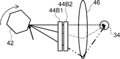
- the wavelength sweeping unit 32 replaces the bandpass filter 44A with a long pass filter 44B1 arranged on the third optical scanner 42 side and a short pass filter 44B2 arranged on the detector 34 side. I have.
- the short pass filter 44B2 may be arranged on the third optical scanner 42 side, and the long pass filter 44B1 may be arranged on the detector 34 side.
- each of the long-pass filter 44B1 and the short-pass filter 44B2 is composed of a multilayer film having a uniform structure in which the interference light is irradiated and passes through, and the wavelength of the interference light passing through differs depending on the incident angle.
- the long-pass filter 44B1 as a whole allows interference light having a wavelength in the first range to pass through
- the short-pass filter 44B2 as a whole allows interference light having a wavelength in the second range shorter than the first range. Passes.
- the long-pass filter 44B1 and the short-pass filter 44B2 pass the interference light having a wavelength within the predetermined range of the wavelength of the interference light that the band-pass filter 44A shown in FIG. 2A passes through as a whole. That is, the overlapping range of the first range and the second range is the predetermined range.
- the interference light is scanned by the third optical scanner 42, and each time the interference light is positioned from the top to the bottom of the paper surface of FIG.
- the short pass filter 44B2 every time the interference light passing through the long pass filter 44B1 is positioned from the top to the bottom of the paper surface of FIG. 2B, the interference light of ⁇ k or less passes through the short pass filter 44B2, and as a result, the long pass is performed.
- Light of only ⁇ k passes through each position of the filter 44B1 from the top to the bottom of the paper surface of FIG. 2B.
- the entire wavelength range of ⁇ k is the above-mentioned predetermined range.
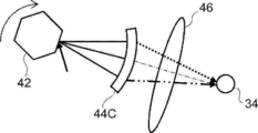
- the wavelength sweeping unit 32 includes a bandpass filter 44C instead of the bandpass filter 44A.
- the bandpass filter 44C is configured so that the wavelength of the passing light is different for each different position through which the light passes, even if the incident angle is the same. As a whole, the bandpass filter 44C allows interference light having a wavelength in the above predetermined range to pass through.
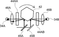
- the wavelength sweeping unit 32 of the fourth example divides the interference light into two, reflects the interference light to the third optical scanner 42, and passes the interference light through the beam splitter 45A and the beam splitter 45A. It includes a mirror 45B that reflects the other interference light that has passed through to the third optical scanner 42.
- the beam splitter 45A and the mirror 45B separately incident the interference light on two different surfaces of the third optical scanner 42.
- the bandpass filter 44AA and the other interference light reflected by the mirror 45B are transferred to the third optical scanner 42 at a position where one interference light reflected by the beam splitter 45A is scanned by the third optical scanner 42.
- a bandpass filter 44AB is provided at a position scanned by.
- the wavelength sweeping unit 32 includes a detector 34A that detects the interference light that has passed through the bandpass filter 44AA and a detector 34B that detects the interference light that has passed through the bandpass filter 44AB.
- the wavelength sweeping unit 32 includes an optical system 46A that guides the interference light that has passed through the bandpass filter 44AA to the detector 34A, and an optical system 46B that guides the interference light that has passed through the bandpass filter 44AB to the detector 34B. ..
- the bandpass filter 44AA and the bandpass filter 44AB have different wavelengths of the interference light passing through depending on the incident angle, but the wavelength range of the interference light passing through as a whole is configured to be different from each other.
- the wavelength range of the interference light that the bandpass filter 44AA passes through as a whole is the range from the center to the short wavelength side of the predetermined range
- the wavelength range of the interference light that the bandpass filter 44AB passes through as a whole is. It is a range from the center of the above predetermined range to the long wavelength side.
- the third optical scanner 42 incidents the interference light on the bandpass filter 44AA and the bandpass filter 44AB, which have different wavelength ranges of the interference light passing through, while changing the angle with time, and the wavelength corresponding to the incident angle. Only the interference light of is passed. By detecting the passing interference light with different detectors 34A and 34B, intensity information for each wavelength is obtained.
- the fourth configuration can extend the wavelength range to be swept and shorten the time required for wavelength sweeping.
- the interference light is divided into two, and each is incident on two bandpass filters 44AA and bandpass filters 44AB having different wavelength ranges of the passing interference light.
- the technique of the present disclosure is not limited to this, and the interfering light is divided into three or more, and each is incident on three or more bandpass filters having different wavelength ranges of the interfering light passing through. You may.
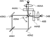
- wavelength sweeping unit 32 of the fifth example has the same constituent parts as those of the fourth example, the same parts are designated by the same reference numerals, the description thereof will be omitted, and only the different parts will be described.
- the wavelength sweeping unit 32 divides the interference light into two, reflects the interference light of one, and passes through the other interference light, the beam splitter 45N1 and the mirror 45N3 that reflects the reflected interference light.
- the mirror 45N2 that reflects the other interference light and the mirror 45N4 that is rotatably arranged are provided.
- the mirror 45N3 reflects one interference light to one reflecting surface of the mirror 45N4, and the mirror 45N2 reflects the other interference light to the other reflecting surface of the mirror 45N4.
- the mirror 45N4 rotates, one reflecting surface scans one interference light, and the other reflecting surface scans the other interference light.
- the bandpass filter 44AA is arranged on the side where one interference light is scanned, and the bandpass filter 44AB is arranged on the side where the other interference light is scanned.
- One of the interference lights that have passed through the bandpass filter 44AA is guided to the detector 34A by the optical system 46AA and detected.
- the other interference light that has passed through the bandpass filter 44AB is guided to the detector 34B by the optical system 46B and detected.
- the wavelength range to be swept can be extended and the time required for wavelength sweeping can be shortened.
- the mirror 45N3 and the mirror 45N2 are replaced with a beam splitter, the interference light is further divided, and the interference light passing through the beam splitter is rotatably arranged by the mirror.
- the interference light that has passed through the other bandpass filter may be scanned by the other bandpass filter and guided to another detector by the optical system for detection.
- the wavelength sweeping unit 32 of the sixth example has the same constituent parts as those of the first example, the same parts are designated by the same reference numerals, the description thereof will be omitted, and only the different parts will be described.
- the bandpass filter 44A of the wavelength sweeping unit 32 is rotatably arranged so that the incident angle of the interference light changes with time.
- the wavelength sweeping unit 32 includes a rotation mechanism 48 that rotates the bandpass filter 44A so that the incident angle of the interference light changes with time.
- the detector 34 is arranged before passing through the bandpass filter 44A.
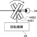
- the wavelength sweeping unit 32 of the seventh example has the same components as those of the first example and the sixth example, different parts will be described.
- the long pass filter 44B1 and the short pass filter 44B2 instead of the bandpass filter 44A in the sixth example, the long pass filter 44B1 and the short pass filter 44B2 have the rotation mechanism 48, and the incident angle of the interference light changes with time. Rotate to do.
- the interference light that has passed through the bandpass filter 44A or the longpass filter 44B1 and the shortpass filter 44B2 can be transmitted without using the optical system 46. It reaches one point of the detection unit of the detector 34. Therefore, in the sixth example and the seventh wavelength sweeping unit 32, a point detector (photodiode or the like) can be used as the detector 34 without using the optical system 46.
- the long pass filter 44B1 and the short pass filter 44B2 are provided.
- the techniques of the present disclosure are not limited to this.
- one surface of one (glass) substrate having a first surface and a second surface facing the first surface is one of the first surface and the second surface.
- a long-pass filter film may be formed on the other surface, and a short-pass filter film may be formed on the other surface.
- FIG. 5 shows a block diagram of the measuring device according to the second embodiment.
- the measuring device of the second embodiment corresponds to OCT (full field OCT) in which a predetermined region (not one point) of the fundus of the eye 60 to be inspected is collectively photographed.
- OCT full field OCT
- the broadband light source 12 of the measuring device of the second embodiment generates a luminous flux including coherent light of a plurality of wavelengths.
- An LED can be used as the broadband light source 12.
- the interferometer 14 divides the light having a predetermined luminous flux into a measurement luminous flux and a reference luminous flux. As the interferometer 14, a beam splitter or the like is used.
- This measuring device includes a projection optical system 72 that guides the measured luminous flux to the measurement area of the fundus of the eye 60 to be examined, instead of the first optical scanner 16 and the second optical scanner 18.
- the measurement area of the object to be measured is collectively irradiated with the measurement luminous flux.
- the irradiation position of the measured luminous flux can be moved by a scanner (not shown) included in the projection optical system, and the measurement area can be moved.
- the detection unit 74 of this measuring device includes a tunable wavelength filter 82 that sweeps the wavelength of the interference light every hour, and an area detector 84.
- the tunable wavelength filter 82 may be, for example, a Fabry-Perot spectroscope, an AOTF (acousto-optic tunable filter), or the like that changes the wavelength to be extracted with time.
- the area detector 84 is arranged so as to be conjugate with the retina of the fundus of the eye 60 to be inspected.
- the interferometer 14 combines the measured luminous flux reflected by the fundus of the eye 60 with the reference luminous flux and emits it as an interferometric luminous flux to the tunable wavelength filter 82 of the detection unit 74.
- the tunable wavelength filter 82 sweeps the wavelength of the interfering luminous flux every hour.
- the interference light flux that has passed through the tunable wavelength filter 82 is detected by the area detector 84.
- the wavelength swept every hour by the tunable wavelength filter 82 is predetermined. Therefore, the area detector 84 outputs the intensity information of the interference light to the image processing device 54 in the order of the predetermined wavelengths.
- the image processing device 54 generates a tomographic image of the measurement region of the fundus of the eye 60 to be inspected by Fourier transforming the intensity information of each wavelength. Therefore, full-field OCT can be realized with a simple configuration by sweeping the spectral wavelength.
- a light source that emits broadband light An interference unit that divides the light emitted by the light source into measurement light and reference light, irradiates the object with the measurement light collectively, and generates interference light between the reflected light reflected by the object and the reference light.
- a sweeping unit that sweeps the interference light to light of a different wavelength over time A detection unit that detects interference light swept by light of a different wavelength for each time, It is a measuring device equipped with The sweeping unit includes a tunable filter that sweeps the interference light of the predetermined luminous flux to light having a different wavelength every time. Measuring device.
- the first embodiment and the second embodiment described above are intended to acquire a tomographic image of the fundus (rear eye portion) of the eye 60 to be inspected, but the technique of the present disclosure is not limited to this.
- it can be applied to the acquisition of a tomographic image of the anterior segment of the eye 60 to be inspected.
- the target for acquiring the tomographic image may be various parts of the living body such as teeth, esophagus, bronchi, and large intestine.
- it can be applied not only to living organisms but also to tomographic imaging of minerals and parts.
- SS-OCT wavelength sweep type OCT
Landscapes
- Health & Medical Sciences (AREA)
- Life Sciences & Earth Sciences (AREA)
- General Health & Medical Sciences (AREA)
- Physics & Mathematics (AREA)
- Surgery (AREA)
- Public Health (AREA)
- Ophthalmology & Optometry (AREA)
- Engineering & Computer Science (AREA)
- Biomedical Technology (AREA)
- Heart & Thoracic Surgery (AREA)
- Medical Informatics (AREA)
- Molecular Biology (AREA)
- Radiology & Medical Imaging (AREA)
- Animal Behavior & Ethology (AREA)
- Nuclear Medicine, Radiotherapy & Molecular Imaging (AREA)
- Biophysics (AREA)
- Veterinary Medicine (AREA)
- Chemical & Material Sciences (AREA)
- Analytical Chemistry (AREA)
- Biochemistry (AREA)
- General Physics & Mathematics (AREA)
- Immunology (AREA)
- Pathology (AREA)
- Investigating Or Analysing Materials By Optical Means (AREA)
- Eye Examination Apparatus (AREA)
Abstract
Description
以下、本開示の技術の第1の実施形態に係る計測装置について図面を参照して説明する。計測装置は、物体の断層画像を取得する光干渉断層計(OCT、Optical Coherence Tomography)である。
図1には、第1の実施の形態の計測装置のブロック図が示されている。図1に示すように、計測装置は、複数の異なる波長のコヒーレント光(ブロードバンド光)を同時に発生させるブロードバンド光源12を備えている。
ミラーで反射した参照光は干渉計14に戻る。
第3光学スキャナ42により干渉光が走査され、図2Bの紙面の上から下に、干渉光が位置する毎に、λk以上(k=1、2、3、・・・、n)の干渉光がロングパスフィルタ44B1を通過する。次に、ショートパスフィルタ44B2で、図2Bの紙面の上から下に、ロングパスフィルタ44B1を通過した干渉光が位置する毎に、λk以下の干渉光がショートパスフィルタ44B2を通過し、結果、ロングパスフィルタ44B1における図2Bの紙面の上から下の各位置において、λkのみの光が通過する。なお、λkの全体の波長の範囲は、上記所定範囲である。
次に、本開示の技術の第2の実施の形態を説明する。第2の実施の形態の構成は、第1の実施の形態の構成と同様の部分があるので、同一部分には同一の符号を付してその説明を省略し、異なる部分のみを説明する。
よって、分光波長掃引することでフルフィールドOCTを簡単な構成で実現できる。
前記光源により発せられた光を測定光と参照光とに分割し、前記測定光が物体に一括で照射され、前記物体で反射した反射光と、前記参照光との干渉光を発生させる干渉部と、
前記干渉光を、時間毎に異なる波長の光に掃引する掃引部と、
前記時間毎に異なる波長の光に掃引された干渉光を検出する検出部と、
を備える計測装置であって、
前記掃引部は、前記所定の光束の干渉光を、時間毎に異なる波長の光に掃引する波長可変フィルタを備える、
計測装置。
14 干渉計
16 第1光学スキャナ
18 第2光学スキャナ
20 参照光学系
22 検出部
24 制御部
32 波長掃引部
34、34A、34B 検出器
42 第3光学スキャナ
44、44A、44AA、44AB、44C バンドパスフィルタ
44B1 ロングパスフィルタ
44B2 ショートパスフィルタ
45A ビームスプリッタ
45B ミラー
45N1 ビームスプリッタ
45N2、45N3、45N4 ミラー
46、46A、46B 光学系
48 回転機構
52 動作制御装置
54 画像処理装置
60 被検眼
72 投影光学系
74 検出部
82 チューナブル波長フィルタ
84 エリア検出器
Claims (12)
- ブロードバンド光を発する光源と、
前記ブロードバンド光を測定光と参照光とに分割し、前記測定光が物体に照射され反射した測定光と、前記参照光との干渉光を発生させる干渉部と、
前記干渉光を、波長掃引する掃引部と、
前記掃引部から出力された干渉光を検出する検出部と、
を備える計測装置。 - 前記掃引部は、
入射角度により異なる波長の光を出力するバンドパスフィルタと、
前記バンドパスフィルタに向けて前記干渉光を走査する掃引走査部と、
から構成されていることを特徴とする請求項1に記載の計測装置。 - 前記バンドパスフィルタは、前記干渉光が通過する領域が一様の構造で構成されていることを特徴とする請求項2に記載の計測装置。
- 前記バンドパスフィルタは、前記干渉光が通過する領域が一様の構造の多層膜で構成されていることを特徴とする請求項2又は請求項3に記載の計測装置。
- 前記掃引走査部は反射面を有し、
前記反射面の角度が変化することにより前記干渉光が前記バンドパスフィルタを走査することにより、前記干渉光のバンドパスフィルタに対する入射角度が変化することを特徴とする
請求項2から4の何れか1項に記載の計測装置。 - 前記入射角度によって、前記バンドパスフィルタを通過した前記干渉光の波長が異なるように、前記バンドパスフィルタが構成されていることを特徴とする請求項5に記載の計測装置。
- 前記掃引走査部は、ポリゴンミラーであることを特徴とする、
請求項2から6の何れか1項に記載の計測装置。 - 前記掃引部と前記検出部の間に、前記バンドパスフィルタを通過した干渉光を前記検出部に集光させる集光光学系をさらに有することを特徴とする
請求項2から7の何れか1項に記載の計測装置。 - 前記測定光を、前記物体において走査する測定光走査部を更に備え、
前記掃引走査部は第1周波数で駆動され、前記測定光走査部は前記第1周波数より低い第2周波数で駆動することを特徴とする、
請求項2から8の何れか1項に記載の計測装置。 - 前記検出部は、前記掃引部で掃引される波長掃引幅の光を受光するポイントセンサーであることを特徴とする請求項1から9の何れか1項に記載の計測装置。
- 前記検出部の検出信号に基づいて、前記物体の断層画像を生成する画像生成部をさらに備えることを特徴とする請求項1から10の何れか1項に記載の計測装置。
- 前記物体は、被検眼の前眼部あるいは後眼部である、
請求項1から請求項11の何れか1項に記載の計測装置。
Priority Applications (4)
| Application Number | Priority Date | Filing Date | Title |
|---|---|---|---|
| JP2021525413A JP7276444B2 (ja) | 2019-06-10 | 2019-06-10 | 計測装置 |
| US17/616,754 US12285216B2 (en) | 2019-06-10 | 2019-06-10 | Measurement device |
| PCT/JP2019/022927 WO2020250272A1 (ja) | 2019-06-10 | 2019-06-10 | 計測装置 |
| JP2023074886A JP7444314B2 (ja) | 2019-06-10 | 2023-04-28 | 計測装置 |
Applications Claiming Priority (1)
| Application Number | Priority Date | Filing Date | Title |
|---|---|---|---|
| PCT/JP2019/022927 WO2020250272A1 (ja) | 2019-06-10 | 2019-06-10 | 計測装置 |
Publications (1)
| Publication Number | Publication Date |
|---|---|
| WO2020250272A1 true WO2020250272A1 (ja) | 2020-12-17 |
Family
ID=73780863
Family Applications (1)
| Application Number | Title | Priority Date | Filing Date |
|---|---|---|---|
| PCT/JP2019/022927 Ceased WO2020250272A1 (ja) | 2019-06-10 | 2019-06-10 | 計測装置 |
Country Status (3)
| Country | Link |
|---|---|
| US (1) | US12285216B2 (ja) |
| JP (2) | JP7276444B2 (ja) |
| WO (1) | WO2020250272A1 (ja) |
Citations (6)
| Publication number | Priority date | Publication date | Assignee | Title |
|---|---|---|---|---|
| JPH06167448A (ja) * | 1991-04-26 | 1994-06-14 | Siemens Plessey Controls Ltd | 光学的ガス検出器 |
| JP2005347668A (ja) * | 2004-06-07 | 2005-12-15 | Sun Tec Kk | 波長走査型ファイバレーザ光源 |
| JP2009503519A (ja) * | 2005-07-28 | 2009-01-29 | バイオプティジェン,インコーポレイテッド | 低減された実効線幅を有する光コヒーレンス撮像システム及びそれを使用する方法 |
| JP2011089887A (ja) * | 2009-10-22 | 2011-05-06 | Sun Tec Kk | 光断層画像表示システム |
| US20110273721A1 (en) * | 2009-11-09 | 2011-11-10 | Kulkarni Manish D | Novel compact, affordable optical test, measurement or imaging device |
| US20190117078A1 (en) * | 2017-09-12 | 2019-04-25 | Sonendo, Inc. | Optical systems and methods for examining a tooth |
Family Cites Families (13)
| Publication number | Priority date | Publication date | Assignee | Title |
|---|---|---|---|---|
| DE3617123C2 (de) * | 1985-07-04 | 1997-03-20 | Cammann Karl | Verfahren zur Selektivitätsverbesserung spektrometrischer Messungen sowie Vorrichtung zur Durchführung des Verfahrens |
| US6404482B1 (en) * | 1992-10-01 | 2002-06-11 | Nikon Corporation | Projection exposure method and apparatus |
| US20020090650A1 (en) | 2000-04-06 | 2002-07-11 | Quantum Dot Corporation | Two-dimensional spectral imaging system |
| JP2003344650A (ja) * | 2002-05-24 | 2003-12-03 | Nikon Corp | 光学薄膜フィルタおよび光学装置 |
| WO2005047813A1 (en) * | 2003-10-27 | 2005-05-26 | The General Hospital Corporation | Method and apparatus for performing optical imaging using frequency-domain interferometry |
| JP2006024876A (ja) * | 2004-06-07 | 2006-01-26 | Sun Tec Kk | 波長走査型ファイバレーザ光源 |
| US7417741B2 (en) | 2004-09-01 | 2008-08-26 | Oti Ophthalmic Technologies Inc. | Transmissive scanning delay line for optical coherence tomography |
| JP2007085832A (ja) * | 2005-09-21 | 2007-04-05 | Omron Corp | 光学式レーダ装置 |
| JP2007309880A (ja) | 2006-05-22 | 2007-11-29 | Fujifilm Corp | 波長掃引光源および光断層画像化装置 |
| JP5412247B2 (ja) * | 2009-11-11 | 2014-02-12 | キヤノン電子株式会社 | 光学フィルタ |
| WO2012131812A1 (ja) * | 2011-03-31 | 2012-10-04 | コニカミノルタアドバンストレイヤー株式会社 | 分光器 |
| CN105682538B (zh) | 2013-10-29 | 2018-07-03 | 尼德克株式会社 | 眼科观察装置及眼科观察程序的存储介质 |
| WO2015116756A1 (en) | 2014-01-31 | 2015-08-06 | Jds Uniphase Corporation | An optical filter and spectrometer |
-
2019
- 2019-06-10 WO PCT/JP2019/022927 patent/WO2020250272A1/ja not_active Ceased
- 2019-06-10 US US17/616,754 patent/US12285216B2/en active Active
- 2019-06-10 JP JP2021525413A patent/JP7276444B2/ja active Active
-
2023
- 2023-04-28 JP JP2023074886A patent/JP7444314B2/ja active Active
Patent Citations (6)
| Publication number | Priority date | Publication date | Assignee | Title |
|---|---|---|---|---|
| JPH06167448A (ja) * | 1991-04-26 | 1994-06-14 | Siemens Plessey Controls Ltd | 光学的ガス検出器 |
| JP2005347668A (ja) * | 2004-06-07 | 2005-12-15 | Sun Tec Kk | 波長走査型ファイバレーザ光源 |
| JP2009503519A (ja) * | 2005-07-28 | 2009-01-29 | バイオプティジェン,インコーポレイテッド | 低減された実効線幅を有する光コヒーレンス撮像システム及びそれを使用する方法 |
| JP2011089887A (ja) * | 2009-10-22 | 2011-05-06 | Sun Tec Kk | 光断層画像表示システム |
| US20110273721A1 (en) * | 2009-11-09 | 2011-11-10 | Kulkarni Manish D | Novel compact, affordable optical test, measurement or imaging device |
| US20190117078A1 (en) * | 2017-09-12 | 2019-04-25 | Sonendo, Inc. | Optical systems and methods for examining a tooth |
Also Published As
| Publication number | Publication date |
|---|---|
| JP7276444B2 (ja) | 2023-05-18 |
| JP2023103301A (ja) | 2023-07-26 |
| JPWO2020250272A1 (ja) | 2020-12-17 |
| US20220330815A1 (en) | 2022-10-20 |
| JP7444314B2 (ja) | 2024-03-06 |
| US12285216B2 (en) | 2025-04-29 |
Similar Documents
| Publication | Publication Date | Title |
|---|---|---|
| US9820645B2 (en) | Ophthalmologic apparatus | |
| CN102105105B (zh) | 扩展范围成像 | |
| JP4262603B2 (ja) | トラッキング支援光コヒーレンストモグラフィー | |
| CN102192896B (zh) | 光干涉测量方法及光干涉测量装置 | |
| JP5279524B2 (ja) | 光断層撮像装置、光断層撮像方法 | |
| JP5743380B2 (ja) | 光断層撮像装置および光断層撮像方法 | |
| JP5054072B2 (ja) | 光断層画像撮像装置 | |
| JP5725697B2 (ja) | 情報処理装置および情報処理方法 | |
| JP5064159B2 (ja) | 光断層画像化装置 | |
| US20070086011A1 (en) | Optical tomography method | |
| JP4344829B2 (ja) | 偏光感受光画像計測装置 | |
| JP2006101927A (ja) | 眼科装置 | |
| GB2407155A (en) | Spectral interferometry method and apparatus | |
| JP4907227B2 (ja) | 眼内寸法測定装置 | |
| JP6405037B2 (ja) | 瞬時時間領域光コヒーレンストモグラフィ | |
| RU2561867C2 (ru) | Устройство и способ для оптической когерентной томографии | |
| EP2834618A1 (en) | Optical coherence tomography apparatus and optical coherence tomography method | |
| KR20170139126A (ko) | 촬상 장치 | |
| JP4874906B2 (ja) | 光断層画像取得方法及び光断層画像化装置 | |
| JP7444314B2 (ja) | 計測装置 | |
| JP5828811B2 (ja) | 撮像装置及びその制御方法 | |
| JP5905711B2 (ja) | 光画像計測装置 | |
| KR101436745B1 (ko) | 분광계를 이용하여 파장별 측정을 구현하는 형상 측정 장치 | |
| WO2019202761A1 (ja) | 分光器、撮像装置、走査装置、及び位置測定装置 | |
| JP7777004B2 (ja) | 眼科撮影装置、眼科撮影装置の制御方法、及びプログラム |
Legal Events
| Date | Code | Title | Description |
|---|---|---|---|
| 121 | Ep: the epo has been informed by wipo that ep was designated in this application |
Ref document number: 19933029 Country of ref document: EP Kind code of ref document: A1 |
|
| ENP | Entry into the national phase |
Ref document number: 2021525413 Country of ref document: JP Kind code of ref document: A |
|
| NENP | Non-entry into the national phase |
Ref country code: DE |
|
| 122 | Ep: pct application non-entry in european phase |
Ref document number: 19933029 Country of ref document: EP Kind code of ref document: A1 |
|
| WWG | Wipo information: grant in national office |
Ref document number: 17616754 Country of ref document: US |