WO2020246509A1 - フレネルレンズ、及び画像観察装置 - Google Patents
フレネルレンズ、及び画像観察装置 Download PDFInfo
- Publication number
- WO2020246509A1 WO2020246509A1 PCT/JP2020/021981 JP2020021981W WO2020246509A1 WO 2020246509 A1 WO2020246509 A1 WO 2020246509A1 JP 2020021981 W JP2020021981 W JP 2020021981W WO 2020246509 A1 WO2020246509 A1 WO 2020246509A1
- Authority
- WO
- WIPO (PCT)
- Prior art keywords
- optical axis
- fresnel lens
- ineffective
- prism
- angle
- Prior art date
- Legal status (The legal status is an assumption and is not a legal conclusion. Google has not performed a legal analysis and makes no representation as to the accuracy of the status listed.)
- Ceased
Links
Images




Classifications
-
- G—PHYSICS
- G02—OPTICS
- G02B—OPTICAL ELEMENTS, SYSTEMS OR APPARATUS
- G02B3/00—Simple or compound lenses
- G02B3/02—Simple or compound lenses with non-spherical faces
- G02B3/08—Simple or compound lenses with non-spherical faces with discontinuous faces, e.g. Fresnel lens
-
- G—PHYSICS
- G02—OPTICS
- G02B—OPTICAL ELEMENTS, SYSTEMS OR APPARATUS
- G02B27/00—Optical systems or apparatus not provided for by any of the groups G02B1/00 - G02B26/00, G02B30/00
- G02B27/01—Head-up displays
- G02B27/017—Head mounted
- G02B27/0172—Head mounted characterised by optical features
-
- G—PHYSICS
- G02—OPTICS
- G02B—OPTICAL ELEMENTS, SYSTEMS OR APPARATUS
- G02B27/00—Optical systems or apparatus not provided for by any of the groups G02B1/00 - G02B26/00, G02B30/00
- G02B27/01—Head-up displays
- G02B27/0101—Head-up displays characterised by optical features
- G02B2027/0118—Head-up displays characterised by optical features comprising devices for improving the contrast of the display / brillance control visibility
- G02B2027/012—Head-up displays characterised by optical features comprising devices for improving the contrast of the display / brillance control visibility comprising devices for attenuating parasitic image effects
Definitions
- the present invention relates to a Fresnel lens and an image observation device.
- a Fresnel lens is composed of a plurality of prisms arranged from the optical axis toward the outer circumference of the lens.
- the Fresnel lens is disclosed in Patent Document 1 below.
- Each prism has a substantially triangular cross section and has an effective surface and an ineffective surface.
- the effective surface faces the outer circumference of the Fresnel lens and is inclined with respect to the optical axis.
- the effective surface corresponds to a convex lens having a desired optical performance obtained by dividing the lens surface into a plurality of annular regions.
- the non-effective surface faces the optical axis and is parallel to the optical axis.
- the light of the image reaches not only the effective surface of the prism but also the ineffective surface.
- This light is reflected by the non-effective surface and may reach the observer's eyes.
- the light reflected by the ineffective surface and reaching the observer's eyes causes flare. That is, it appears that the light spreads around the light emitting point in the image due to the light reflected on the non-effective surface.
- An example of the Fresnel lens proposed in the present disclosure has a plurality of prisms arranged from the optical axis toward the outer circumference.
- Each of the plurality of prisms has an effective surface that faces the outer periphery of the Fresnel lens and is inclined with respect to the optical axis, and a non-effective surface that faces the optical axis. It has the top of the prism between it and the ineffective surface.
- the ineffective surface has a first surface and a second surface closer to the top of the prism than the first surface, and at least the first surface. The surface of is inclined with respect to the optical axis. According to this Fresnel lens, flare can be suppressed.
- An example of the image observation device proposed in the present disclosure includes the Fresnel lens and a display element. According to this image observation device, flare can be suppressed.
- the ineffective surface may be bent at the boundary between the first surface and the second surface.
- the ineffective surface may be entirely curved, some of which may function as the first surface and some of which may function as the second surface.
- both the first surface and the second surface may be inclined with respect to the optical axis. In this case, the angle between the first surface and the second surface with respect to the optical axis may be the same.
- FIG. 5 is an enlarged cross-sectional view showing the top of a prism having a second ineffective surface.
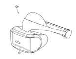
- FIG. 5 is an enlarged cross-sectional view showing the top of a prism having no second non-effective surface. It is a figure which shows the head-mounted display which is an example of an image observation apparatus.
- the Fresnel lens proposed in the present disclosure will be described below.
- the Fresnel lens 10 shown in FIG. 1 and the like will be described as an example of the Fresnel lens proposed in the present disclosure.
- the Fresnel lens 10 is mounted on an image observation device having a display element.
- the Fresnel lens 10 is used as an eyepiece optical system in a head-mounted display 100 (see FIG. 6).
- the head-mounted display 100 has a display element ID arranged in front of the user (observer).
- the display element ID is, for example, a liquid crystal display device, an organic EL (electroluminescence) display device, a micro LED display device, or the like.
- two Fresnel lenses 10 are arranged side by side.
- the Fresnel lens 10 In the head-mounted display 100, in addition to the Fresnel lens 10, another Fresnel lens located in the direction of the optical axis Z1 with respect to the Fresnel lens 10 may also be used.
- the image observation device on which the Fresnel lens 10 is mounted is not limited to the head-mounted display 100, and may be applied to, for example, an electronic viewfinder of a camera.
- the plurality of prisms 11 are arranged on a plane intersecting the optical axis Z1 (for example, a plane perpendicular to the optical axis 1, a concave surface, a convex surface, etc.).
- the Fresnel lens 10 is arranged so that the prism 11 projects toward the display element ID.
- the Fresnel lens 10 may be arranged such that the prism 11 projects toward the observer's pupil.
- each prism 11 When the Fresnel lens 10 is viewed in the direction of the optical axis Z1, each prism 11 is an annular shape centered on the optical axis Z1.
- the plurality of prisms 11 are arranged in the radial direction (direction orthogonal to the optical axis Z1) when the Fresnel lens 10 is viewed in the direction of the optical axis Z1.
- Each prism 11 has an effective surface Es and an ineffective surface Ns. Further, each prism 11 has a top portion 11c between the effective surface Es and the non-effective surface Ns.
- the effective surface Es faces the outer circumference of the Fresnel lens 10 and is inclined with respect to the optical axis Z1.
- the effective surface Es is inclined so that the distance from the optical axis Z1 to the normal line De of the effective surface Es increases toward the front side (display element ID side in FIG. 1) of the Fresnel lens 10.
- the effective surface Es corresponds to a convex lens having the optical performance required for an image observation device, in which the lens surface is divided into a plurality of annular regions.
- the Fresnel lens 10 is formed by arranging the divided lens surfaces along a surface (for example, a plane perpendicular to the optical axis 1, a concave surface, a convex surface, etc.) that intersects the optical axis Z1.
- the non-effective surface Ns is a surface facing the optical axis Z1. That is, the normal line Dn of the ineffective surface Ns extends toward the optical axis Z1.
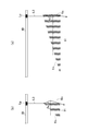
- FIG. 2A is a diagram showing a cross section of the Fresnel lens 10 proposed in the present disclosure.
- the ineffective surface Ns has a slope inclined with respect to the optical axis Z1.
- the ineffective surface Ns is inclined so that the distance from the optical axis Z1 to the ineffective surface Ns increases as it approaches the top 11c.
- the distance between the ineffective surface Ns and the optical axis Z1 is the distance in the direction orthogonal to the optical axis Z1.
- This inclination of the ineffective surface Ns can suppress the occurrence of flare.
- the ineffective surface Ns has a slope, but only in some prisms 11, the ineffective surface Ns may have a slope.
- FIG. 2B is a diagram for explaining the flare generation mechanism caused by the ineffective surface.
- the Fresnel lens 90 whose ineffective surface Ns is parallel to the optical axis Z1 is shown.
- the observer sees the light emitting point Lp of the display element ID
- the light L1 emitted from the light emitting point Lp is refracted by the effective surface Es of the prism 91A and reaches the observer's pupil. From the light emitting point Lp, in addition to the light L1, light that reaches the ineffective surface Ns is generated.
- the light L2 is reflected by the ineffective surface Ns of the prism 91B outside the prism 91A and reaches the observer's pupil.
- the light L3 enters the prism 91C from the effective surface Es of the prism 91C inside the prism 91A, is reflected by the non-effective surface Ns, and reaches the observer's pupil.
- the observer sees the light emitting point Lp of the display element ID, it is reflected not only by the light L1 that is refracted by the effective surface Es and reaches the observer's pupil but also by the ineffective surface Ns and is reflected by the observer's pupil.
- Lights L2 and L3 that reach the area are generated.
- the effective light L1 emitted from the light emitting point Lp is refracted by the effective surface Es of the prism 11A and observed. It reaches the eyes of the person. Further, the above-mentioned ineffective lights L2 and L3 are generated from the light emitting point Lp. (The direction in which the ineffective lights L2 and L3 shown in FIG. 2A exit from the light emitting point Lp is the same as the direction in which the ineffective lights L2 and L3 shown in FIG.
- the non-effective surface Ns is inclined with respect to the optical axis Z1, and an angle ⁇ n is secured between the non-effective surface Ns and the direction of the optical axis Z1. Therefore, the ineffective light L2 is totally reflected by the ineffective surface Ns of the prism 11B outside the prism 11A, but deviates from the position of the observer's pupil. Further, since the non-effective surface Ns is inclined with respect to the optical axis Z1, the non-effective light L3 also deviates from the position of the observer's pupil. In other words, the angle ⁇ n is designed in each prism 11 so that the ineffective lights L2 and L3 deviate from the position of the observer's pupil. Therefore, the occurrence of flare can be suppressed.
- the angle ⁇ n between the ineffective surface Ns and the optical axis Z1 is larger than the draft.
- the "draft" is a slope formed on the surface of the mold in order to facilitate separation between the mold and the molded product (Fresnel lens 10) when the Fresnel lens 10 is molded using the mold.
- the slope is inclined with respect to the separation direction between the mold and the molded product.
- the draft is, for example, 1 to 5 degrees.
- the angle ⁇ n between the ineffective surface Ns and the direction of the optical axis Z1 is larger than, for example, 5 degrees.
- the angle ⁇ n is preferably greater than 15 degrees.
- the angle ⁇ n is more preferably greater than 20 degrees.
- the angle ⁇ n is even more preferably greater than 30 degrees.
- the angle ⁇ n is smaller than 40 degrees. More preferably, the angle ⁇ n is less than 35 degrees.
- the angle ⁇ n of the non-effective surface Ns may change according to the distance from the optical axis Z1 to the prism 11. By doing so, it is possible to more effectively prevent the ineffective lights L2 and L3 from reaching the observer's eyes.
- the angle ⁇ n may increase as the distance from the optical axis Z1 to the prism 11 increases.
- the angle ⁇ n may decrease as the distance from the optical axis Z1 to the prism 11 increases.
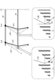
- 3 and 4 are diagrams for explaining the relationship between the distance from the optical axis Z1 to the prism and the angle ⁇ n.
- FIG. 3A represents a prism 91 (a prism in which the ineffective surface Ns is not inclined) close to the optical axis Z1
- FIG. 3B is a prism having a relatively large distance from the optical axis Z1. It represents 91.
- the plurality of effective surfaces Es constituting the Fresnel lens correspond to the divided lens surfaces of the convex lens. Therefore, as shown in FIG. 3A, the inclination of the effective surface Es becomes relatively gentle at a position close to the optical axis Z1, and as shown in FIG. 3B, a position far from the optical axis Z1. Then, the inclination of the effective surface Es becomes relatively steep.
- the angles of incidence ⁇ e1 and ⁇ e2 of the non-effective light L3 on the non-effective surface Ns are closer to the prism 91 ((a) in FIG. 3) than the prism 91 closer to the optical axis Z1 ((a) in FIG. 3).
- b)) becomes smaller.
- the incident angle ⁇ e2 shown in FIG. 3B is smaller than the incident angle ⁇ e1 shown in FIG. 3A.
- the ineffective surface Ns and the optical axis Z1 Even if the angle ⁇ n with respect to the direction is relatively small, it is possible to prevent the ineffective light L3 from reaching the ineffective surface Ns.
- the incident angles ⁇ e1 and ⁇ e2 of the ineffective light L3 with respect to the ineffective surface Ns differ depending on the distance from the optical axis Z1, it is desirable that the angle ⁇ n of the ineffective surface Ns also changes depending on the distance from the optical axis Z1.
- FIG. 4 shows the ineffective lights L21, L22, L23, and L24 emitted from the light emitting points Lp1 and Lp2.
- the ineffective lights L21 and L22 emitted from the light emitting point Lp1 near the optical axis Z1 reach the Fresnel lens 10.
- a part of the ineffective light (light L24) emitted from the light emitting point Lp2 far from the optical axis Z1 passes outside the Fresnel lens 10. Therefore, the closer to the outer peripheral portion of the Fresnel lens 10, the less effective light L2 (see FIG. 2A) reaches the observer's pupil.
- the angle ⁇ n between the ineffective surface Ns and the direction of the optical axis Z1 is small, it is possible to suppress the ineffective light L2 (see FIG. 2A) from reaching the observer's pupil. it can. Therefore, the angle ⁇ n of the non-effective surface Ns may be relatively small on the outer peripheral portion of the Fresnel lens 10.
- FIG. 5A is an enlarged cross-sectional view showing the top portion 11c of the prism 11.
- the prism 11 has a curved surface Cs on its top 11c.
- the Fresnel lens 10 can be easily molded.
- the ineffective surface Ns of the prism 11 includes a first ineffective surface Ns1 relatively far from the top 11c and a second ineffective surface Ns2 relatively close to the top 11c.
- the first ineffective surface Ns1 and the second ineffective surface Ns2 are aligned in the direction of the optical axis Z1.
- the above-mentioned angle ⁇ n is secured between the first ineffective surface Ns1 and the direction of the optical axis Z1.
- the angle ⁇ n of the first non-effective surface Ns1 may change according to the distance from the optical axis Z1 as described with reference to FIGS. 3 and 4.
- the angle between the second ineffective surface Ns2 and the direction of the optical axis Z1 is smaller than the angle ⁇ n between the first ineffective surface Ns1 and the direction of the optical axis Z1.
- FIG. 5A a part of the light emitted from the light emitting point Lp1 (light L4 in FIG. 5A) is refracted by the curved surface Cs and is incident on the prism 11.
- the second ineffective surface Ns2 prevents the light L4 from reaching the observer's pupil.
- FIG. 5B shows a prism 11 that does not have such a second ineffective surface Ns2.
- the position of the light emitting point Lp1 and the direction of the light L4 emitted from the light emitting point Lp1 are the same as those in FIG. 5A.
- FIG. 5B shows a prism 11 that does not have such a second ineffective surface Ns2.
- the ineffective surface Ns when the ineffective surface Ns does not have the second ineffective surface Ns2 and is inclined with respect to the optical axis Z1 as a whole, it is refracted by the curved surface Cs and the ineffective surface Ns. Light L4 traveling along Ns is generated. When this light L4 reaches the observer's eyes, it causes flare.
- the second ineffective surface Ns2 since the second ineffective surface Ns2 is formed on the ineffective surface Ns, the second ineffective surface Ns2 blocks the light L4 and emits light to the observer's pupil. Prevents L4 from reaching.
- the light L5 emitted from the light emitting point Lp2 and reflected by the outer surface of the second ineffective surface Ns2 is blocked by the first ineffective surface Ns1, and the light L5 reaches the observer's pupil. You can also prevent it from happening.
- the second ineffective surface Ns2 is, for example, parallel to the optical axis Z1.
- the second non-effective surface Ns2 may be inclined with respect to the optical axis Z1.
- the angle between the second ineffective surface Ns2 and the optical axis Z1 may be the same as the draft described above, or may be larger than the draft.
- the distance H4 (in the direction along the optical axis Z1) from the top 11c of the prism 11 (the uppermost end of the prism 11) to the boundary M between the second ineffective surface Ns2 and the first ineffective surface Ns1.
- Distance is larger than the diameter of the curved surface Cs.
- the circle R is the circle having the largest diameter among the virtual circles tangent to the inside of the curved surface Cs.
- the diameter of the curved surface Cs is, for example, 3 ⁇ m or more and 20 ⁇ m or less. Therefore, when the diameter of the curved surface Cs is larger than 3 ⁇ m, the distance H4 from the top 11c to the boundary M between the second ineffective surface Ns2 and the first ineffective surface Ns1 is, for example, larger than 3 ⁇ m.
- the distance H4 from the top 11c of the prism 11 to the boundary M between the second ineffective surface Ns2 and the first ineffective surface Ns1 is smaller than half of the height H5 of the prism 11 (see FIG. 2A).
- the distance H4 in this way, the size of the first ineffective surface Ns1 can be secured.
- the height H5 of the prism 11 is the distance from the boundary between the ineffective surface Ns and the effective surface Es of two adjacent prisms 11 to the top 11c (distance in the direction along the optical axis Z1). Is.
- each of the plurality of prisms 11 has an effective surface Es that faces the outside of the Fresnel lens 10 and is inclined with respect to the optical axis Z1, and an ineffective surface Ns that faces the optical axis Z1.
- the top portion 11c of the prism 11 is provided between the effective surface Es and the non-effective surface Ns.
- the ineffective surface Ns has a first ineffective surface Ns1 and a second ineffective surface Ns2 closer to the top 11c of the prism 11 than the first ineffective surface Ns1.
- the first non-effective surface is inclined with respect to the optical axis Z1. According to this structure, it is possible to prevent the ineffective lights L2 and L3 from reaching the observer's pupil and causing flare.
- the Fresnel lens proposed in the present disclosure is not limited to the above-mentioned example of the Fresnel lens 10.
- the angle between the second ineffective surface Ns2 and the direction of the optical axis Z1 may be the same as the angle between the first ineffective surface Ns1 and the direction of the optical axis Z1. That is, the ineffective surface Ns may be a flat flat surface.
- the ineffective surface Ns does not have to be bent at the boundary M between the first ineffective surface Ns1 and the second ineffective surface Ns2. That is, the ineffective surface Ns may be curved as a whole, and the first ineffective surface Ns1 and the second ineffective surface Ns2 may be smoothly connected.
- the ineffective surface Ns has, in addition to the first ineffective surface Ns1 and the second ineffective surface Ns2, a third ineffective surface and a fourth ineffective surface having different angles. You may.
Landscapes
- Physics & Mathematics (AREA)
- General Physics & Mathematics (AREA)
- Optics & Photonics (AREA)
- Devices For Indicating Variable Information By Combining Individual Elements (AREA)
- Optical Elements Other Than Lenses (AREA)
- Lenses (AREA)
- Overhead Projectors And Projection Screens (AREA)
Abstract
Description
Claims (9)
- 光軸から外周に向かって並んでいる複数のプリズムを有しているフレネルレンズにおいて、
前記複数のプリズムのそれぞれは、前記フレネルレンズの外周に向いており前記光軸に対して傾斜している有効面と、前記光軸に向いている非有効面とを有し、前記有効面と前記非有効面との間に前記プリズムの頂部を有し、
前記複数のプリズムのうちの少なくとも1つにおいて、前記非有効面は、第1の面と、前記第1の面よりも前記プリズムの前記頂部に近い第2の面とを有し、少なくとも前記第1の面は前記光軸に対して傾斜している
フレネルレンズ。 - 前記複数のプリズムのうちの前記少なくとも1つにおいて、
前記第2の面と前記光軸との角度は、前記第1の面と前記光軸との角度よりも小さい
請求項1に記載されるフレネルレンズ。 - 前記少なくとも1つのプリズムは、前記頂部に湾曲面を有している
請求項1に記載されるフレネルレンズ。 - 前記頂部から、前記第2の面と前記第1の面との境までの距離は、前記湾曲面の直径より大きい
請求項3に記載されるフレネルレンズ。 - 前記頂部から、前記第2の面と前記第1の面との境までの距離は、前記プリズムの高さの半分よりも小さい
請求項2に記載されるフレネルレンズ。 - 前記複数のプリズムのそれぞれは前記第1の面を有し、
前記第1の面の前記光軸との角度は、前記第1の面の前記光軸からの距離に応じて変化している
請求項1に記載されるフレネルレンズ。 - 前記第1の面と前記光軸の方向との角度は、前記フレネルレンズの抜き勾配よりも大きい
請求項1に記載されるフレネルレンズ。 - 前記第1の面と前記光軸の方向との角度は、5度より大きく、40度以下である
請求項1に記載されるフレネルレンズ。 - 請求項1のフレネルレンズと、表示素子とを有している画像観察装置。
Priority Applications (3)
| Application Number | Priority Date | Filing Date | Title |
|---|---|---|---|
| JP2021524880A JP7506066B2 (ja) | 2019-06-07 | 2020-06-03 | フレネルレンズ、及び画像観察装置 |
| US17/610,196 US12571942B2 (en) | 2019-06-07 | 2020-06-03 | Fresnel lens and image observing device |
| JP2024095969A JP7824356B2 (ja) | 2019-06-07 | 2024-06-13 | フレネルレンズ、及び画像観察装置 |
Applications Claiming Priority (2)
| Application Number | Priority Date | Filing Date | Title |
|---|---|---|---|
| JP2019-107348 | 2019-06-07 | ||
| JP2019107348 | 2019-06-07 |
Publications (1)
| Publication Number | Publication Date |
|---|---|
| WO2020246509A1 true WO2020246509A1 (ja) | 2020-12-10 |
Family
ID=73653202
Family Applications (1)
| Application Number | Title | Priority Date | Filing Date |
|---|---|---|---|
| PCT/JP2020/021981 Ceased WO2020246509A1 (ja) | 2019-06-07 | 2020-06-03 | フレネルレンズ、及び画像観察装置 |
Country Status (3)
| Country | Link |
|---|---|
| US (1) | US12571942B2 (ja) |
| JP (2) | JP7506066B2 (ja) |
| WO (1) | WO2020246509A1 (ja) |
Cited By (2)
| Publication number | Priority date | Publication date | Assignee | Title |
|---|---|---|---|---|
| WO2023032310A1 (ja) * | 2021-08-30 | 2023-03-09 | ソニーグループ株式会社 | 光学素子及び画像表示装置 |
| JPWO2024080378A1 (ja) * | 2022-10-14 | 2024-04-18 |
Families Citing this family (5)
| Publication number | Priority date | Publication date | Assignee | Title |
|---|---|---|---|---|
| USD977545S1 (en) | 2019-03-08 | 2023-02-07 | Abl Ip Holding Llc | Optical cover with faceted surface |
| US12571942B2 (en) | 2019-06-07 | 2026-03-10 | Sony Interactive Entertainment Inc. | Fresnel lens and image observing device |
| CN116299799B (zh) * | 2022-09-09 | 2025-11-07 | 赛尔富电子有限公司 | 一种菲涅尔透镜及包含其的灯具 |
| CN116106995B (zh) * | 2023-02-17 | 2025-05-27 | 北京京东方显示技术有限公司 | 菲涅尔透镜及其制备方法、光学模组及光学成像设备 |
| CN116953824B (zh) * | 2023-09-21 | 2024-02-06 | 江西联昊光电有限公司 | 菲涅尔透镜及其制备方法、光学成像设备 |
Citations (7)
| Publication number | Priority date | Publication date | Assignee | Title |
|---|---|---|---|---|
| JPS61277935A (ja) * | 1985-06-03 | 1986-12-08 | Mitsubishi Rayon Co Ltd | フレネルレンズ付き透過型スクリ−ン |
| JPH0875906A (ja) * | 1994-09-02 | 1996-03-22 | Casio Comput Co Ltd | フレネルレンズ |
| WO2005059641A1 (ja) * | 2003-12-17 | 2005-06-30 | Mitsubishi Denki Kabushiki Kaisha | フレネル光学素子及び投写型表示装置 |
| JP2013068751A (ja) * | 2011-09-21 | 2013-04-18 | Hitachi Maxell Ltd | フレネルレンズおよび照明器具 |
| JP2017129753A (ja) * | 2016-01-20 | 2017-07-27 | パナソニックIpマネジメント株式会社 | フレネルレンズ及びヘッドアップディスプレイ |
| WO2018008249A1 (ja) * | 2016-07-07 | 2018-01-11 | 株式会社ニコン | 接眼光学系およびヘッドマウントディスプレイ |
| US20190250310A1 (en) * | 2018-02-12 | 2019-08-15 | Genius Electronic Optical Co., Ltd. | Fresnel lens |
Family Cites Families (14)
| Publication number | Priority date | Publication date | Assignee | Title |
|---|---|---|---|---|
| US5914760A (en) * | 1996-06-21 | 1999-06-22 | Casio Computer Co., Ltd. | Surface light source device and liquid crystal display device using the same |
| JP2000171613A (ja) * | 1998-12-02 | 2000-06-23 | Kuraray Co Ltd | フレネルレンズシート |
| JP2002221605A (ja) * | 2001-01-26 | 2002-08-09 | Sharp Corp | フレネルレンズ、及びそれを用いた照明装置と表示装置、並びにフレネルレンズの設計方法とその設計装置 |
| JP4212902B2 (ja) | 2003-01-07 | 2009-01-21 | 大日本印刷株式会社 | フレネルレンズ、フレネルレンズ成形型、フレネルレンズ製造方法及びフレネルレンズを用いた透過型スクリーン |
| JP5127530B2 (ja) | 2008-03-26 | 2013-01-23 | 株式会社東芝 | 立体画像表示装置 |
| JP5054730B2 (ja) * | 2009-06-04 | 2012-10-24 | 日本特殊光学樹脂株式会社 | ソーラーシステム用フレネルレンズ及びソーラーシステム |
| JP5192067B2 (ja) * | 2011-09-09 | 2013-05-08 | シャープ株式会社 | フレネルレンズ |
| WO2014017490A1 (ja) * | 2012-07-23 | 2014-01-30 | シャープ株式会社 | 照明装置及び表示装置 |
| FR2995408B1 (fr) | 2012-09-10 | 2016-11-18 | Soitec Solar Gmbh | Lentille de fresnel avec angle de depouille variable |
| JP5716733B2 (ja) | 2012-12-19 | 2015-05-13 | 大日本印刷株式会社 | 採光シート、採光装置、及び建物 |
| JP6089692B2 (ja) | 2012-12-26 | 2017-03-08 | 大日本印刷株式会社 | 採光シート、採光装置、及び建物 |
| WO2016084752A1 (ja) | 2014-11-25 | 2016-06-02 | 大日本印刷株式会社 | 採光シート及び採光積層体 |
| WO2017138480A1 (ja) | 2016-02-09 | 2017-08-17 | 株式会社ソニー・インタラクティブエンタテインメント | フレネルレンズ及びフレネルレンズの製造方法 |
| US12571942B2 (en) | 2019-06-07 | 2026-03-10 | Sony Interactive Entertainment Inc. | Fresnel lens and image observing device |
-
2020
- 2020-06-03 US US17/610,196 patent/US12571942B2/en active Active
- 2020-06-03 WO PCT/JP2020/021981 patent/WO2020246509A1/ja not_active Ceased
- 2020-06-03 JP JP2021524880A patent/JP7506066B2/ja active Active
-
2024
- 2024-06-13 JP JP2024095969A patent/JP7824356B2/ja active Active
Patent Citations (7)
| Publication number | Priority date | Publication date | Assignee | Title |
|---|---|---|---|---|
| JPS61277935A (ja) * | 1985-06-03 | 1986-12-08 | Mitsubishi Rayon Co Ltd | フレネルレンズ付き透過型スクリ−ン |
| JPH0875906A (ja) * | 1994-09-02 | 1996-03-22 | Casio Comput Co Ltd | フレネルレンズ |
| WO2005059641A1 (ja) * | 2003-12-17 | 2005-06-30 | Mitsubishi Denki Kabushiki Kaisha | フレネル光学素子及び投写型表示装置 |
| JP2013068751A (ja) * | 2011-09-21 | 2013-04-18 | Hitachi Maxell Ltd | フレネルレンズおよび照明器具 |
| JP2017129753A (ja) * | 2016-01-20 | 2017-07-27 | パナソニックIpマネジメント株式会社 | フレネルレンズ及びヘッドアップディスプレイ |
| WO2018008249A1 (ja) * | 2016-07-07 | 2018-01-11 | 株式会社ニコン | 接眼光学系およびヘッドマウントディスプレイ |
| US20190250310A1 (en) * | 2018-02-12 | 2019-08-15 | Genius Electronic Optical Co., Ltd. | Fresnel lens |
Cited By (3)
| Publication number | Priority date | Publication date | Assignee | Title |
|---|---|---|---|---|
| WO2023032310A1 (ja) * | 2021-08-30 | 2023-03-09 | ソニーグループ株式会社 | 光学素子及び画像表示装置 |
| JPWO2024080378A1 (ja) * | 2022-10-14 | 2024-04-18 | ||
| JP7554404B2 (ja) | 2022-10-14 | 2024-09-20 | 大日本印刷株式会社 | 光学積層体、転写シート、光学部材、及び移動体 |
Also Published As
| Publication number | Publication date |
|---|---|
| JP7506066B2 (ja) | 2024-06-25 |
| US12571942B2 (en) | 2026-03-10 |
| JPWO2020246509A1 (ja) | 2020-12-10 |
| JP7824356B2 (ja) | 2026-03-04 |
| US20220221621A1 (en) | 2022-07-14 |
| JP2024117790A (ja) | 2024-08-29 |
Similar Documents
| Publication | Publication Date | Title |
|---|---|---|
| JP7824356B2 (ja) | フレネルレンズ、及び画像観察装置 | |
| JP6383569B2 (ja) | 車両用灯具 | |
| CN111373306B (zh) | 光学装置的制造方法 | |
| CN106796352B (zh) | 平视显示装置 | |
| JP6287605B2 (ja) | ヘッドアップディスプレイ装置及びその照明ユニット | |
| WO2017157807A3 (de) | Brillenglas für eine abbildungsoptik und datenbrille | |
| WO2018008833A3 (ko) | 옵티칼 렌즈 어셈블리 및 이를 포함한 전자 장치 | |
| JP2017534352A (ja) | 結像光学系およびスマートグラス | |
| KR20210046611A (ko) | 광학 장치의 제조 방법 | |
| TWI794244B (zh) | 掃描型顯示裝置及掃描型顯示系統 | |
| TWI740172B (zh) | 擋環及採用該擋環的鏡頭 | |
| JP2018101104A5 (ja) | ||
| JP2017129751A5 (ja) | ||
| JP6657943B2 (ja) | ライトガイド及び虚像表示装置 | |
| WO2020045517A1 (ja) | レンズユニット及び画像観察装置 | |
| JP6402854B2 (ja) | 透過型スクリーン及びそれを用いたヘッドアップディスプレイ装置 | |
| US10310276B2 (en) | Virtual reality display apparatus | |
| JP6697253B2 (ja) | 装着型映像表示装置及び接眼光学系 | |
| JP2017010023A5 (ja) | ||
| JP2018194715A (ja) | レンズユニットおよびカメラモジュール | |
| CN113366376B (zh) | 能够提供近距离的增强现实用图像的增强现实用光学装置 | |
| KR102413740B1 (ko) | 차량용 헤드 업 디스플레이 장치 | |
| JP6717273B2 (ja) | ヘッドアップディスプレイ装置 | |
| US12345889B2 (en) | Virtual image display device | |
| TW202020541A (zh) | 墊圈及採用該墊圈的鏡頭 |
Legal Events
| Date | Code | Title | Description |
|---|---|---|---|
| 121 | Ep: the epo has been informed by wipo that ep was designated in this application |
Ref document number: 20817958 Country of ref document: EP Kind code of ref document: A1 |
|
| ENP | Entry into the national phase |
Ref document number: 2021524880 Country of ref document: JP Kind code of ref document: A |
|
| NENP | Non-entry into the national phase |
Ref country code: DE |
|
| 122 | Ep: pct application non-entry in european phase |
Ref document number: 20817958 Country of ref document: EP Kind code of ref document: A1 |
|
| WWG | Wipo information: grant in national office |
Ref document number: 17610196 Country of ref document: US |