WO2020246259A1 - 温調ユニット - Google Patents
温調ユニット Download PDFInfo
- Publication number
- WO2020246259A1 WO2020246259A1 PCT/JP2020/020200 JP2020020200W WO2020246259A1 WO 2020246259 A1 WO2020246259 A1 WO 2020246259A1 JP 2020020200 W JP2020020200 W JP 2020020200W WO 2020246259 A1 WO2020246259 A1 WO 2020246259A1
- Authority
- WO
- WIPO (PCT)
- Prior art keywords
- temperature control
- metal
- control unit
- fiber sheet
- reinforcing member
- Prior art date
- Legal status (The legal status is an assumption and is not a legal conclusion. Google has not performed a legal analysis and makes no representation as to the accuracy of the status listed.)
- Ceased
Links
Images


Classifications
-
- F—MECHANICAL ENGINEERING; LIGHTING; HEATING; WEAPONS; BLASTING
- F28—HEAT EXCHANGE IN GENERAL
- F28D—HEAT-EXCHANGE APPARATUS, NOT PROVIDED FOR IN ANOTHER SUBCLASS, IN WHICH THE HEAT-EXCHANGE MEDIA DO NOT COME INTO DIRECT CONTACT
- F28D1/00—Heat-exchange apparatus having stationary conduit assemblies for one heat-exchange medium only, the media being in contact with different sides of the conduit wall, in which the other heat-exchange medium is a large body of fluid, e.g. domestic or motor car radiators
- F28D1/02—Heat-exchange apparatus having stationary conduit assemblies for one heat-exchange medium only, the media being in contact with different sides of the conduit wall, in which the other heat-exchange medium is a large body of fluid, e.g. domestic or motor car radiators with heat-exchange conduits immersed in the body of fluid
- F28D1/03—Heat-exchange apparatus having stationary conduit assemblies for one heat-exchange medium only, the media being in contact with different sides of the conduit wall, in which the other heat-exchange medium is a large body of fluid, e.g. domestic or motor car radiators with heat-exchange conduits immersed in the body of fluid with plate-like or laminated conduits
-
- F—MECHANICAL ENGINEERING; LIGHTING; HEATING; WEAPONS; BLASTING
- F28—HEAT EXCHANGE IN GENERAL
- F28D—HEAT-EXCHANGE APPARATUS, NOT PROVIDED FOR IN ANOTHER SUBCLASS, IN WHICH THE HEAT-EXCHANGE MEDIA DO NOT COME INTO DIRECT CONTACT
- F28D1/00—Heat-exchange apparatus having stationary conduit assemblies for one heat-exchange medium only, the media being in contact with different sides of the conduit wall, in which the other heat-exchange medium is a large body of fluid, e.g. domestic or motor car radiators
- F28D1/02—Heat-exchange apparatus having stationary conduit assemblies for one heat-exchange medium only, the media being in contact with different sides of the conduit wall, in which the other heat-exchange medium is a large body of fluid, e.g. domestic or motor car radiators with heat-exchange conduits immersed in the body of fluid
- F28D1/04—Heat-exchange apparatus having stationary conduit assemblies for one heat-exchange medium only, the media being in contact with different sides of the conduit wall, in which the other heat-exchange medium is a large body of fluid, e.g. domestic or motor car radiators with heat-exchange conduits immersed in the body of fluid with tubular conduits
- F28D1/053—Heat-exchange apparatus having stationary conduit assemblies for one heat-exchange medium only, the media being in contact with different sides of the conduit wall, in which the other heat-exchange medium is a large body of fluid, e.g. domestic or motor car radiators with heat-exchange conduits immersed in the body of fluid with tubular conduits the conduits being straight
-
- F—MECHANICAL ENGINEERING; LIGHTING; HEATING; WEAPONS; BLASTING
- F28—HEAT EXCHANGE IN GENERAL
- F28F—DETAILS OF HEAT-EXCHANGE AND HEAT-TRANSFER APPARATUS, OF GENERAL APPLICATION
- F28F1/00—Tubular elements; Assemblies of tubular elements
- F28F1/10—Tubular elements and assemblies thereof with means for increasing heat-transfer area, e.g. with fins, with projections, with recesses
- F28F1/40—Tubular elements and assemblies thereof with means for increasing heat-transfer area, e.g. with fins, with projections, with recesses the means being only inside the tubular element
-
- H—ELECTRICITY
- H05—ELECTRIC TECHNIQUES NOT OTHERWISE PROVIDED FOR
- H05K—PRINTED CIRCUITS; CASINGS OR CONSTRUCTIONAL DETAILS OF ELECTRIC APPARATUS; MANUFACTURE OF ASSEMBLAGES OF ELECTRICAL COMPONENTS
- H05K7/00—Constructional details common to different types of electric apparatus
- H05K7/20—Modifications to facilitate cooling, ventilating, or heating
Definitions
- the present invention relates to a temperature control unit.
- Patent Document 1 is made of a metal fiber for the purpose of excellent cooling effect, easy miniaturization and thinning, and enabling local cooling. It has a metal fiber sheet and a cooling mechanism for cooling the metal fiber sheet, and the cooling mechanism includes an accommodating body for accommodating the metal fiber sheet and a refrigerant introducing means for introducing a refrigerant into the accommodating body.
- the cooling member to be provided is disclosed. According to this cooling member, the cooling effect can be enhanced by increasing the pressure of the refrigerant introduced into the housing to increase the flow velocity of the refrigerant.
- the present invention has been made in view of the above, and an object of the present invention is to obtain a temperature control unit having a high temperature control effect that suppresses deformation due to pressure of a heat medium in the containment body.
- the present invention which solves the above-mentioned problems and achieves the object, has a temperature control mechanism through which a heat medium passes, and the temperature control mechanism includes a metal porous body and an accommodating body for accommodating the metal porous body.
- the temperature control mechanism includes a metal porous body and an accommodating body for accommodating the metal porous body.
- the housing at least one main surface is exposed to the outside of the temperature control mechanism, and the inside of the main surface is in contact with the metal porous body to be between the metal porous body and the outside.
- the metal porous body is a metal fiber sheet composed of metal fibers.
- the reinforcing member is arranged so as to be overlapped on the outside of the housing.
- the reinforcing member is arranged so as to cover a side surface portion substantially perpendicular to one main surface of the rectangular parallelepiped temperature control mechanism.
- the reinforcing member is arranged so as to cover the entire surface of the temperature control mechanism.
- the present invention has a temperature control mechanism through which a heat medium passes, and the temperature control mechanism includes a metal porous body and an accommodating body for accommodating the metal porous body. At least one main surface is exposed to the outside of the temperature control mechanism, and the inside of the main surface is in contact with the metal porous body to exchange heat between the metal porous body and the outside, and the accommodating body. It is a temperature control unit including a reinforcing member for reinforcing the temperature control mechanism with a heat insulating material covering the temperature control mechanism.
- the metal porous body is a metal fiber sheet composed of metal fibers.
- the temperature control unit includes a rod-shaped member inserted into at least a part of the housing and the metal fiber sheet.
- the temperature control unit is provided with a nut that is screwed with the rod-shaped member.
- the present invention has a temperature control mechanism through which a heat medium passes, and the temperature control mechanism includes a metal porous body and an accommodating body for accommodating the metal porous body. At least one main surface is exposed to the outside of the temperature control mechanism, and the inside of the main surface is in contact with the metal porous body to exchange heat between the metal porous body and the outside, and the temperature control is performed. It is a temperature control unit including a reinforcing member provided in the mechanism and functioning as a column or a beam.
- the metal porous body is a metal fiber sheet composed of metal fibers.
- the reinforcing member has a plate shape or a rod shape.
- the reinforcing member extends to the outside of the housing.
- thermocontrol unit having a high temperature control effect that suppresses deformation due to pressure of the heat medium in the containment body.
- FIG. It is a figure which shows the partial cross section of the temperature control unit which concerns on Embodiment 1.
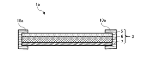
- FIG. It is a figure which shows the partial cross section of the 1st modification of the temperature control unit which concerns on Embodiment 1.
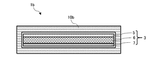
- FIG. It is a figure which shows the partial cross section of the 2nd modification of the temperature control unit which concerns on Embodiment 1.
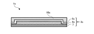
- FIG. It is a figure which shows the partial cross section of the temperature control unit which concerns on Embodiment 2.
- the "metal fiber” means a fiber containing a metal as a main component
- the “copper fiber” means a fiber containing a copper as a main component.
- the "thermal conductivity (W / (m ⁇ K))” is a value measured by a laser flash method (for example, a laser flash thermal constant measuring device "TC7000 type” manufactured by ULVAC Riko Co., Ltd.).
- the "average fiber diameter" is calculated by calculating the cross-sectional area perpendicular to the longitudinal direction of the metal fiber based on the vertical cross-sections at a plurality of points of the metal fiber sheet imaged with a microscope, and the same area as the cross-sectional area is calculated.
- the additive average value of the area diameter derived by calculating the diameter of the perfect circle.
- the plurality of locations can be, for example, 20 locations.
- the "average fiber length” refers to an arithmetic mean value of values obtained by measuring the length of a plurality of randomly selected fibers in the longitudinal direction in a microscope image. If the fiber is not straight, the length of the curve along the fiber is used.
- the plurality of lines can be, for example, 20 lines.
- the "space factor” refers to the ratio of the fiber portion to the volume of the fiber sheet, and is calculated from the basis weight, thickness and true density of the fiber by the following formula.
- the space factor can be calculated by adopting a true density value that reflects the composition ratio of each fiber.
- (Space factor (%)) (Fiber sheet basis weight) / ((Fiber sheet thickness) x (True density)) x 100.
- the "sheet thickness” refers to the case where, for example, the measurement point of the metal fiber sheet is measured by a film thickness meter (for example, "Digimatic Indicator ID-C112X” manufactured by Mitutoyo Co., Ltd.) that drops terminals by air.
- the arithmetic mean value of. “Homogeneity” refers to a small amount of variation in the sheet having characteristics such as electrical properties, physical properties, and air permeability properties of the sheet composed of fibers.
- CV coefficient of variation
- the "porosity” refers to the ratio of the portion where the void exists to the volume of the fiber sheet, and is calculated by the following formula from the basis weight, thickness, and true density of the fiber of the fiber sheet.
- the space factor can be calculated by adopting a true density value that reflects the composition ratio of each fiber.
- the heat medium used in the temperature control unit of the present invention may be a gas, a liquid, or the like, and the properties thereof are not limited. That is, the heat medium used in the temperature control unit of the present invention may be a gas such as air, a liquid such as water or alcohol, or fluorine such as hydrofluorocarbon or hydrofluoroether. It may be a system compound or the like.
- FIG. 1 is a diagram showing a partial cross section of the temperature control unit 1 according to the present embodiment.
- the temperature control unit 1 shown in FIG. 1 includes a temperature control mechanism 3 through which a heat medium passes, a heat medium introduction port and a heat medium discharge port (not shown).
- a heat medium is introduced into the temperature control mechanism 3 from the outside through the heat medium introduction port, and the heat medium is discharged to the outside from the heat medium discharge port.
- the heat medium introduction port is provided with a static mixer in order to generate turbulence in the heat medium to be introduced and diffuse it.
- the heat medium include water, air, and a fluorine-based solvent.
- the temperature control mechanism 3 accommodates a metal fiber sheet 6 composed of metal fibers, an accommodating body 5 that accommodates the metal fiber sheet 6 and is closed by a heat exchange plate 7, and one main surface is exposed to the outside.
- a heat exchange plate 7 for exchanging heat between the metal fiber sheet 6 and the outside is provided by providing the back surface of one main surface in contact with the metal fiber sheet 6.
- the metal fiber sheet 6 may be composed of the metal fiber alone, or may be composed of a component other than the metal fiber.
- the metal component of the metal fiber include copper, stainless steel, iron, aluminum, nickel, chromium, and precious metals. Of these, copper, stainless steel, and aluminum are preferable, and copper is particularly preferable. This is because copper fibers have an excellent balance between rigidity and plastic deformability.
- precious metals include gold, platinum, silver, palladium, rhodium, iridium, ruthenium and osmium.
- polyethylene terephthalate PET: Poly-Ethylene Terephthalate
- polyvinyl alcohol PVA: Poly-Vinyl Alcohol
- polyolefin polyvinyl chloride
- PVC Poly-) Vinyl Chloride
- acrylics organic substances that impart binding and supportability to fibrous materials
- organic substances that impart binding and supportability to fibrous materials can be exemplified.
- the metal fiber sheet 6 is a non-woven fabric in which a plurality of metal fibers are randomly entangled, by containing one or a plurality of these organic substances, the shape retention and function at the time of producing the metal fiber sheet 6 are maintained. It can assist or improve sexuality.
- the metal fiber sheet 6 it is preferable that a plurality of adjacent metal fibers are bonded to each other. That is, in the metal fiber sheet 6, it is preferable that the plurality of metal fibers are physically fixed and a binding portion is formed between the plurality of metal fibers. In the metal fiber sheet 6, a plurality of metal fibers may be directly fixed at a binding portion or indirectly, but between the plurality of metal fibers constituting the metal fiber sheet 6. It is preferable that voids are formed at least partially. This is because when such voids are formed in the metal fiber sheet 6, the heat medium described later is easily introduced into the metal fiber sheet 6.
- the plurality of metal fibers are sintered in the binding portion because the thermal conductivity and homogeneity of the metal fiber sheet 6 are stable.
- the voids formed between the plurality of metal fibers may be formed by entanglement of the metal fibers.
- the porosity of the metal fiber sheet 6 is preferably 5% or more and 99% or less, and more preferably 10% or more and 98% or less.
- the thermal conductivity of the metal fiber sheet 6 is preferably 5 W / (m ⁇ K) or more.
- the metal fiber sheet 6 may be a sheet-like structure, may be a non-woven fabric in which a plurality of metal fibers are randomly entwined, or may be a woven fabric or a mesh material having regularity. Further, the surface of the metal fiber sheet 6 may be flat or may be corrugated and uneven.
- the basis weight of the metal fiber sheet 6 is preferably 10 g / m 2 or more and 1000 g / m 2 or less.
- the basis weight of the metal fiber sheet 6 is 10 g / m 2 or more, the cooling or heating effect can be enhanced, and when the basis weight of the metal fiber sheet 6 is 1000 g / m 2 or less, the weight of the metal fiber sheet 6 is reduced. be able to.
- the average fiber diameter of the metal fibers of the metal fiber sheet 6 is preferably 1 ⁇ m or more and 30 ⁇ m or less, and particularly preferably 2 ⁇ m or more and 20 ⁇ m or less.
- the average fiber length of the metal fibers of the metal fiber sheet 6 is for stabilizing the thermal conductivity and homogeneity of the metal fiber sheet 6.
- it is preferably 1 mm or more and 10 mm or less.
- the aspect ratio of the metal fibers of the metal fiber sheet 6 is less than 33, the metal fibers are less likely to be entangled.
- the aspect ratio of the metal fibers of the metal fiber sheet 6 exceeds 10,000, the homogeneity of the metal fiber sheet 6 is lowered. Therefore, the aspect ratio of the metal fiber is preferably 33 or more and 10000 or less.
- the space factor of the metal fiber sheet 6 is preferably 2% or more, more preferably 4% or more, particularly preferably 5% or more, preferably 65% or less, and more preferably 60% or less.
- the CV value which is the coefficient of variation of the basis weight specified in JIS Z8101 per 1 cm 2 of the metal fiber sheet 6, is preferably 10% or less.
- the method for producing the metal fiber sheet 6 is not limited to a specific method.
- a plain weave in which metal wires are crossed one by one may be used, or a metal wire arranged in the vertical direction and a metal arranged in the horizontal direction may be used.
- a twill weave may be used in which the wires are crossed so as to get over two or more of each other.
- tatami mats, flat tatami mats or twill tatami mats may be used.
- the metal wires may be welded in a crossed state without knitting.
- a method of papermaking by a wet papermaking method can be exemplified.
- wet papermaking is performed with a paper machine using a slurry in which metal fibers and the like are dispersed in an aqueous medium.
- the slurry may contain additives such as fillers, dispersants, thickeners, defoamers, paper strength enhancers, sizing agents, coagulants, colorants and fixing agents.
- the wet body sheet obtained by the wet papermaking method may be subjected to a fiber entanglement treatment step in which a plurality of metal fibers are entangled with each other.
- a method of injecting a high-pressure jet water stream onto one main surface of the wet body sheet can be exemplified.
- metal fibers or fibers containing metal fibers can be entangled over the entire wet body sheet.
- This wet body sheet undergoes a dryer step by hot air drying after the fiber entanglement treatment step.
- This dryer step is preferably carried out in an inert gas atmosphere using a vacuum sintering furnace. The sheet that has undergone the dryer process is cooled to room temperature and then wound up.
- the sheet obtained through the fiber entanglement treatment step and the dryer step may be subjected to a pressing step before binding a plurality of metal fibers.
- a pressing step it is possible to reduce the excessively large voids existing between the plurality of metal fibers, so that the homogeneity can be improved.
- the thickness of the metal fiber sheet 6 can be adjusted by adjusting the pressure during the pressing process.
- the bonding portion between the plurality of metal fibers is sintered by the sintering step.
- the sintering step the binding between the plurality of metal fibers can be reliably performed, the plurality of metal fibers are fixed, the CV value of the basis weight of the metal fiber sheet 6 is stable, and the metal fiber sheet 6 is used. Stable homogeneity and thermal conductivity.
- the metal fiber sheet 6 that has undergone the sintering step further undergoes a pressing step.
- the metal fiber sheet 6 is further subjected to a pressing process after the sintering process, the homogeneity of the metal fiber sheet 6 can be further improved and the metal fiber sheet 6 can be made thinner.
- the metal fibers move not only in the thickness direction but also in the surface direction of the metal fiber sheet 6.
- the metal fibers are arranged in the places that were voids at the time of sintering, the homogeneity of the metal fiber sheet 6 is improved, and this state is maintained by the plastic deformability of the metal fibers.
- a dry method of compression molding the sheet may be used.
- a web mainly composed of metal fibers is produced by a card method, an airlaid method, or the like, and the web is compression-molded.
- a binder may be impregnated into a plurality of metal fibers to bond the plurality of metal fibers.
- the binder include an organic binder such as an acrylic adhesive and an inorganic binder such as colloidal silica.
- the accommodating body 5 is a structure for accommodating the metal fiber sheet 6.
- metal and ceramic can be exemplified.
- metal material stainless steel, copper and aluminum can be exemplified.
- ceramic material alumina, zirconia, barium titanate, silicon carbide, silicon nitride and aluminum nitride can be exemplified.
- the heat exchange plate 7 includes a surface subject to temperature adjustment on one main surface, is in contact with the metal fiber sheet 6 on the back surface of the surface subject to temperature adjustment, and exchanges heat between the surface subject to temperature adjustment and the metal fiber sheet 6. It is a member.
- the material of the heat exchange plate 7 it is preferable to use a material having high thermal conductivity, and examples of the material having high thermal conductivity include stainless steel, copper and aluminum. Further, if the metal fiber sheet 6 is in contact with the heat exchange plate 7 and the sintering step is performed, the metal fiber sheet 6 and the heat exchange plate 7 are bonded to each other, which is preferable.
- the sintering step is preferably carried out in an inert gas atmosphere using a vacuum sintering furnace.
- a sealing member which is a member formed of a joining material for joining the housing body 5, is arranged between the housing body 5 and the heat exchange plate 7.
- a metal bonding material or an organic bonding material can be used.
- the metal bonding material include silver brazing, phosphor copper brazing, solder and copper foil.
- the metal bonding material preferably has a thermal conductivity of 50 W / (m ⁇ K) or more and a thickness of 100 ⁇ m or less.
- the organic bonding material include thermosetting epoxy, urethane, and silicone.
- the organic bonding material has a low thermal conductivity of less than 1 W / (m ⁇ K), it is preferably thin from the viewpoint of thermal conductivity, and its thickness is preferably 20 ⁇ m or less.
- the sealing member for example, the heat exchange plate 7 and the heat exchange plate 5 are combined by sintering or a thermosetting reaction in a state where the housing body 5 is placed on a member in which the metal fiber sheet 6 and the heat exchange plate 7 are bonded. It is preferable to join.
- the temperature control unit 1 shown in FIG. 1 when the pressure of the heat medium to be introduced is increased, the amount of heat transferred by the heat medium increases, and the temperature control effect, which is a cooling effect or a heating effect, is enhanced, but the heat in the housing 5 is increased. If the pressure of the medium is increased, the temperature control unit may be deformed. Therefore, the temperature control unit according to the present embodiment is provided with a reinforcing member.
- the reinforcing member 10 is arranged so as to overlap the upper surface of the housing body 5, which is one main surface of the temperature control mechanism 3.
- the material of the reinforcing member 10 include aluminum, copper, alumite, stainless steel, and resin.
- the material of the reinforcing member 10 is a material having high heat conductivity such as aluminum, copper, alumite, or stainless steel, when the temperature control unit of the present invention is used for cooling, the temperature covered by the reinforcing member 10 This is preferable because heat is dissipated from the entire tuning unit 1.
- a gap may be formed between the temperature control unit 1 and the reinforcing member 10, it is preferable that an organic film is arranged.
- deformation of the upper surface is mainly suppressed by the reinforcing members 10 arranged so as to be overlapped on the outside of the housing body 5.
- FIG. 2 is a diagram showing a partial cross section of a first modification of the temperature control unit according to the present embodiment.
- the temperature control unit 1a shown in FIG. 2 is the same except that the reinforcing member 10a is provided in place of the reinforcing member 10 of the temperature control unit 1 shown in FIG.
- the reinforcing member 10a is arranged so as to cover at least a side surface portion substantially perpendicular to one main surface of the rectangular parallelepiped temperature control mechanism 3.
- the reinforcing member 10a also covers a part of one main surface of the temperature control mechanism 3.
- the reinforcing member 10a differs only in shape from the reinforcing member 10.
- the reinforcing member 10a fixes the side surface, so that the deformation of the entire temperature control unit 1a is suppressed.
- the thickness of the temperature control unit 1a after the reinforcing member 10a is provided can be made uniform. It is possible.
- FIG. 3 is a diagram showing a partial cross section of a second modification of the temperature control unit according to the present embodiment.
- the temperature control unit 1b shown in FIG. 3 is the same except that the reinforcing member 10b is provided in place of the reinforcing member 10 of the temperature control unit 1 shown in FIG.
- the reinforcing member 10b is arranged so as to cover the entire surface of the temperature control mechanism 3.
- the reinforcing member 10b differs only in shape from the reinforcing member 10.
- the overall deformation is suppressed by the reinforcing member 10b.
- the reinforcing member 10b when the reinforcing member 10b is formed of a material having high thermal conductivity, heat is dissipated from the entire surface of the temperature control unit 1b when the temperature control unit of the present invention is used for cooling. This makes it possible to increase heat dissipation efficiency.
- a material having high thermal conductivity a metal can be exemplified.
- a temperature control unit having a high temperature control effect which suppresses deformation due to pressure of the heat medium in the containment body by insulating while covering a part of the containment body and insulates a surface other than the heat exchange plate, will be described. ..
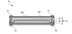
- FIG. 4 is a diagram showing a partial cross section of the temperature control unit 1c according to the present embodiment.
- the temperature control unit 1c shown in FIG. 4 is different in that the temperature control mechanism 3c is provided in place of the temperature control mechanism 3 in the temperature control unit 1 shown in FIG. 1 and the reinforcing member 10c is provided in place of the reinforcing member 10. It is the same.
- the temperature control mechanism 3c accommodates the metal fiber sheet 6c composed of metal fibers, the accommodating body 5c that accommodates the metal fiber sheet 6c and is closed by the heat exchange plate 7, and one main surface is exposed to the outside.
- a heat exchange plate 7 for exchanging heat between the metal fiber sheet 6c and the outside is provided by providing the back surface of one main surface in contact with the metal fiber sheet 6.
- the metal fiber sheet 6c differs from the metal fiber sheet 6 only in that the end portion is thinner than the metal fiber sheet 6.
- the housing body 5c is different from the housing body 5 only in that the end portion is deformed along the shape of the metal fiber sheet 6c.
- the reinforcing member 10c is a structure capable of insulating while reinforcing the temperature control unit 1c.
- resin can be exemplified.
- the resin material include fluororesins such as polyacrylic acid resin, polyvinylpyrrolidone resin, polyester resin, polypropylene resin, and polytetrafluoroethylene, polyimide resin, polyamide resin, and polyparaphenylene benzobisoxazole resin. ..
- the reinforcing member 10c may be formed of the above-mentioned material and then heat-insulated using a known heat-insulating material such as rock wool.
- the reinforcing member 10c is arranged so as to cover all surfaces other than the surface on which the heat exchange plate 7 of the temperature control mechanism 3c is arranged. In the temperature control unit 1c shown in FIG. 4, the reinforcing member 10c insulates a surface other than the surface on which the heat exchange plate 7 is arranged and suppresses deformation.
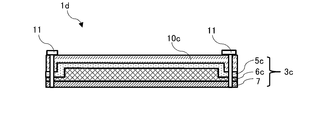
- FIG. 5 is a diagram showing a partial cross section of a first modification of the temperature control unit according to the present embodiment.
- the temperature control unit 1d shown in FIG. 5 is the same except that the screw 11 which is a rod-shaped member is added to the temperature control unit 1c shown in FIG. Examples of the rod-shaped member include screws, pins, and welding materials.
- the screw 11 is inserted into at least a part of the housing 5c, the metal fiber sheet 6c, and the heat exchange plate 7 at the position of the thin end portion of the metal fiber sheet 6c.
- the reinforcing member 10c insulates a surface other than the surface on which the heat exchange plate 7 is arranged and suppresses deformation. Can suppress peeling between the housing 5c and the metal fiber sheet 6c, and between the metal fiber sheet 6c and the heat exchange plate 7.
- FIG. 6 is a diagram showing a partial cross section of a second modification of the temperature control unit according to the present embodiment.
- the temperature control unit 1e shown in FIG. 6 is the same except that the nut 12 is added to the temperature control unit 1d shown in FIG. 5 and the reinforcing member 10e is added.
- As the material of the reinforcing member 10e a metal material can be exemplified. Further, the screw 11 and the nut 12 are screwed together.
- the temperature control unit 1e shown in FIG. 6 similarly to the temperature control unit 1d shown in FIG.
- the reinforcing member 10e insulates a surface other than the surface on which the heat exchange plate 7 is arranged and suppresses deformation, and accommodates the unit. Peeling between the body 5c and the metal fiber sheet 6c and between the metal fiber sheet 6c and the heat exchange plate 7 can be more reliably suppressed.
- the surface other than the surface on which the heat exchange plate is arranged is insulated, and the temperature control having a high temperature control effect in which deformation due to the pressure of the heat medium in the accommodation body is suppressed You can get units.
- a temperature control unit having a high temperature control effect in which deformation due to pressure of the heat medium in the accommodation body is suppressed by providing the temperature control unit with a metal member, will be described.
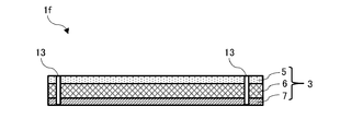
- FIG. 7 is a diagram showing a partial cross section of the temperature control unit 1f according to the present embodiment.
- the temperature control unit 1f shown in FIG. 7 is the same except that the reinforcing member 13 is provided for the temperature control mechanism 3 of the temperature control unit 1 shown in FIG. 1.
- the reinforcing member 13 is driven into, for example, the temperature control mechanism 3.
- the reinforcing member 13 is a plate-shaped or rod-shaped member that functions as a column or a beam in the temperature control unit 1f.
- the reinforcing member 13 suppresses deformation due to pressure of the heat medium in the accommodation body and improves the mechanical strength inside the temperature control unit 1f.
- FIG. 8 is a diagram showing a partial cross section of a modified example of the temperature control unit according to the present embodiment.
- the temperature control unit 1g shown in FIG. 8 is the same except that the reinforcing member 14 is provided for the temperature control mechanism 3 of the temperature control unit 1 shown in FIG.
- the reinforcing member 14 is driven into, for example, the temperature control mechanism 3.
- the reinforcing member 14 is a member that functions as a column or a beam in the temperature control unit 1g. Unlike the reinforcing member 13, the reinforcing member 14 extends to the outside of the accommodating body 5, and can improve the mechanical strength of the surface on which the accommodating body 5 is arranged. In the temperature control unit 1g shown in FIG. 8, the reinforcing member 14 suppresses deformation due to the pressure of the heat medium in the accommodation body and the mechanical strength inside the temperature control unit 1g, similarly to the temperature control unit 1f shown in FIG. Further, the mechanical strength of the surface on which the housing 5 is arranged is also improved.
- the reinforcing member 14 at the portion in contact with the heat exchange plate 7 may be joined to the heat exchange plate 7 by welding or a thermosetting adhesive.
- the reinforcing member 14 may be fastened by a fastening member to be screwed, as in FIG.
- thermocontrol unit having a high internal mechanical strength and a high temperature control effect while suppressing deformation due to pressure of the heat medium in the containment body.
- the temperature control unit is provided with a metal fiber sheet, it may be provided with a porous metal instead of the metal fiber sheet, and the metal fiber sheet and the porous metal are collectively metal porous. Make it a plaque.
- the metal fiber sheet includes a metal fiber non-woven fabric, a metal fiber woven fabric, and a metal mesh.
- the temperature control unit includes a temperature adjustment target surface in the heat exchange plate 7, but the present invention is not limited to this, and heat exchange is performed instead of the heat exchange plate 7.
- a plate-shaped member that is not used may be provided, and a surface subject to temperature adjustment may be included on the housing body side.
- the heat exchange plate may include the temperature control target surface, and the housing may include the temperature control target surface.
- the temperature control target surfaces are formed on both sides of the temperature control unit.
- the temperature control unit of the present invention does not have to be provided with a plate-shaped member, and when the plate-shaped member is not provided, one or more main surfaces of the accommodating body are exposed to the outside of the temperature control mechanism. When the inner surface of the main surface is in contact with the porous metal body, the portion of the accommodating body including the main surface functions to exchange heat between the porous metal body and the outside.
- the present invention also includes a configuration in which each of the above-described embodiments is combined.
- the configuration of the second embodiment and the configuration of the third embodiment may be combined.
Landscapes
- Engineering & Computer Science (AREA)
- Physics & Mathematics (AREA)
- Thermal Sciences (AREA)
- Mechanical Engineering (AREA)
- General Engineering & Computer Science (AREA)
- Geometry (AREA)
- Microelectronics & Electronic Packaging (AREA)
- Cooling Or The Like Of Electrical Apparatus (AREA)
- Control Of Temperature (AREA)
- Inorganic Insulating Materials (AREA)
- Commercial Cooking Devices (AREA)
- Heat-Exchange Devices With Radiators And Conduit Assemblies (AREA)
Abstract
収容体内における熱媒体の圧力による変形を抑えた温調効果の高い温調ユニットを得ることを目的とし、熱媒体が通過する温調機構(3)を有し、温調機構(3)は、金属多孔質体と、金属多孔質体を収容する収容体(5)と、を備え、収容体(5)は、少なくとも1つの主面が温調機構(3)の外側に露出され、該主面の内側が金属多孔質体に接することで金属多孔質体と外部との間の熱交換を行い、温調機構(3)を外側から補強する補強部材(10)と、を備える温調ユニット(1)とする。
Description
本発明は、温調ユニットに関する。
一般に、電気機器の使用電力が増大すると発熱量が増加して電気機器が高温となり、誤作動及び故障等の原因となる。
そこで、電気機器には、発生した熱を冷却及び放熱するための冷却部材を備えることが多い。
そこで、電気機器には、発生した熱を冷却及び放熱するための冷却部材を備えることが多い。
このような冷却部材の従来技術の一例として、特許文献1には、冷却効果に優れ、小型化及び薄型化しやすく、局所的な冷却を可能とすることを目的として、金属繊維で構成されている金属繊維シートと、該金属繊維シートを冷却する冷却機構と、を有し、該冷却機構が、該金属繊維シートを収容する収容体と、該収容体内に冷媒を導入する冷媒導入手段と、を備える冷却部材が開示されている。
この冷却部材によれば、収容体内に導入する冷媒の圧力を高めて冷媒の流速を高めると、冷却効果を高めることができる。
この冷却部材によれば、収容体内に導入する冷媒の圧力を高めて冷媒の流速を高めると、冷却効果を高めることができる。
しかしながら、上記従来技術の一例である特許文献1に示す冷却部材では、冷却効果を高めるために収容体内における冷媒の圧力を高くすると、冷却部材である温調ユニットに変形を生じることがある。
これは、収容体内の温度を上昇させる場合にも同様のことがいえ、加熱効果を高めるために収容体内における熱媒の圧力を高くすると、温調ユニットに変形を生じることがある。
すなわち、温調効果を高めるために収容体内における熱媒体の圧力を高くすると、温調ユニットに変形を生じるおそれがある。
これは、収容体内の温度を上昇させる場合にも同様のことがいえ、加熱効果を高めるために収容体内における熱媒の圧力を高くすると、温調ユニットに変形を生じることがある。
すなわち、温調効果を高めるために収容体内における熱媒体の圧力を高くすると、温調ユニットに変形を生じるおそれがある。
本発明は、上記に鑑みてなされたものであって、収容体内における熱媒体の圧力による変形を抑えた温調効果の高い温調ユニットを得ることを目的とする。
上述の課題を解決して目的を達成する本発明は、熱媒体が通過する温調機構を有し、前記温調機構は、金属多孔質体と、前記金属多孔質体を収容する収容体と、を備え、前記収容体は、少なくとも1つの主面が前記温調機構の外側に露出され、該主面の内側が前記金属多孔質体に接することで前記金属多孔質体と外部との間の熱交換を行い、前記温調機構を外側から補強する補強部材と、を備える温調ユニットである。
前記温調ユニットにおいて、前記金属多孔質体が金属繊維を含んで構成された金属繊維シートであることが好ましい。
前記温調ユニットにおいて、前記補強部材が、前記収容体の外側に重ねて配置されていることが好ましい。
前記温調ユニットにおいて、前記補強部材が、直方体状の前記温調機構の一主面に略垂直な側面部を覆って配置されていることが好ましい。
前記温調ユニットにおいて、前記補強部材が、前記温調機構の全面を覆って配置されていることが好ましい。
又は、本発明は、熱媒体が通過する温調機構を有し、前記温調機構は、金属多孔質体と、前記金属多孔質体を収容する収容体と、を備え、前記収容体は、少なくとも1つの主面が前記温調機構の外側に露出され、該主面の内側が前記金属多孔質体に接することで前記金属多孔質体と外部との間の熱交換を行い、前記収容体を覆う断熱材料によって前記温調機構を補強する補強部材と、を備える温調ユニットである。
前記温調ユニットにおいて、前記金属多孔質体が金属繊維を含んで構成された金属繊維シートであることが好ましい。
前記温調ユニットにおいて、前記収容体及び前記金属繊維シートの少なくとも一部に差し込まれている棒状部材を備えることが好ましい。
前記温調ユニットにおいて、前記棒状部材と螺合するナットを備えることが好ましい。
又は、本発明は、熱媒体が通過する温調機構を有し、前記温調機構は、金属多孔質体と、前記金属多孔質体を収容する収容体と、を備え、前記収容体は、少なくとも1つの主面が前記温調機構の外側に露出され、該主面の内側が前記金属多孔質体に接することで前記金属多孔質体と外部との間の熱交換を行い、前記温調機構に設けられた柱又は梁として機能する補強部材と、を備える温調ユニットである。
前記温調ユニットにおいて、前記金属多孔質体が金属繊維を含んで構成された金属繊維シートであることが好ましい。
前記温調ユニットにおいて、前記補強部材が板状又は棒状であることが好ましい。
又は、前記温調ユニットにおいて、前記補強部材が前記収容体の外側にも延在していることが好ましい。
本発明によれば、収容体内における熱媒体の圧力による変形を抑えた温調効果の高い温調ユニットを得ることができる。
本発明の実施形態について図面を参照して以下に説明する。
ただし、本発明は、以下の実施形態の記載によって限定解釈されるものではない。
なお、以下の説明において、同じ構成には同じ符号を付すものとする。
ただし、本発明は、以下の実施形態の記載によって限定解釈されるものではない。
なお、以下の説明において、同じ構成には同じ符号を付すものとする。
まず、以下の説明において用いる用語を定義する。
「金属繊維」とは、金属を主成分とする繊維をいい、例えば「銅繊維」とは、銅を主成分とする繊維をいう。
また、金属を主成分とする場合には、不可避的に含まれる不純物を含め、本発明の効果を妨げない限り、当該金属以外の成分を一定量含んでいてもよい。
また、「熱伝導率(W/(m・K))」は、レーザーフラッシュ法(例えば、アルバック理工株式会社製、レーザーフラッシュ熱定数測定装置「TC7000型」)により測定される値である。
また、「平均繊維径」とは、顕微鏡で撮像された金属繊維シートの複数の箇所における垂直断面に基づいて、金属繊維の長手方向に垂直な断面積を算出し、当該断面積と同一面積を有する真円の直径を算出することにより導かれた面積径の相加平均値をいう。
ここで、複数の箇所は、例えば、20箇所とすることができる。
また、「平均繊維長」とは、顕微鏡像において、ランダムに選択した複数本の繊維について、繊維の長手方向の長さを測定した値の相加平均値をいう。
なお、繊維が直線状でない場合には、繊維に沿った曲線の長さとする。
ここで、複数本は、例えば、20本とすることができる。
また、「占積率」とは、繊維シートの体積に対する繊維部分の占める割合をいい、繊維シートの坪量、厚さ及び繊維の真密度から以下の式により算出される。
ここで、繊維シートが複数の種類の繊維を含む場合には、各繊維の組成比率を反映した真密度値を採用することで占積率を算出することができる。
(占積率(%))=(繊維シートの坪量)/((繊維シートの厚さ)×(真密度))×100。
ここで、「シートの厚さ」とは、空気による端子落下方式の膜厚計(例えば、ミツトヨ社製「デジマチックインジケータID-C112X」)により、例えば、金属繊維シートの測定点を測定した場合の相加平均値をいう。
「均質性」とは、繊維で構成されるシートの電気特性、物理特性及び透気特性等のシートが有する特性のシート内におけるバラツキの少なさをいう。
均質性の指標として、例えば、1cm2当たりのJIS Z8101に規定する坪量の変動係数(CV(Coefficient of Variation)値)を採用することができる。
「空隙率」とは、繊維シートの体積に対して空隙が存在する部分の割合をいい、繊維シートの坪量、厚さ、及び繊維の真密度から以下の式により算出される。
繊維シートが複数の種類の繊維を含む場合には、各繊維の組成比率を反映した真密度値を採用することで占積率を算出することができる。
(空隙率(%))=(1-(繊維シートの坪量)/((繊維シートの厚さ)×(真密度)))×100。
本発明の温調ユニットに用いられる熱媒体は、気体であってもよいし、液体等であってもよく、その性状について限定されるものではない。
すなわち、本発明の温調ユニットに用いられる熱媒体は、空気のような気体であってもよいし、水又はアルコールのような液体であってもよいし、ハイドロフルオロカーボン又はハイドロフルオロエーテル等のフッ素系の化合物等であってもよい。
「金属繊維」とは、金属を主成分とする繊維をいい、例えば「銅繊維」とは、銅を主成分とする繊維をいう。
また、金属を主成分とする場合には、不可避的に含まれる不純物を含め、本発明の効果を妨げない限り、当該金属以外の成分を一定量含んでいてもよい。
また、「熱伝導率(W/(m・K))」は、レーザーフラッシュ法(例えば、アルバック理工株式会社製、レーザーフラッシュ熱定数測定装置「TC7000型」)により測定される値である。
また、「平均繊維径」とは、顕微鏡で撮像された金属繊維シートの複数の箇所における垂直断面に基づいて、金属繊維の長手方向に垂直な断面積を算出し、当該断面積と同一面積を有する真円の直径を算出することにより導かれた面積径の相加平均値をいう。
ここで、複数の箇所は、例えば、20箇所とすることができる。
また、「平均繊維長」とは、顕微鏡像において、ランダムに選択した複数本の繊維について、繊維の長手方向の長さを測定した値の相加平均値をいう。
なお、繊維が直線状でない場合には、繊維に沿った曲線の長さとする。
ここで、複数本は、例えば、20本とすることができる。
また、「占積率」とは、繊維シートの体積に対する繊維部分の占める割合をいい、繊維シートの坪量、厚さ及び繊維の真密度から以下の式により算出される。
ここで、繊維シートが複数の種類の繊維を含む場合には、各繊維の組成比率を反映した真密度値を採用することで占積率を算出することができる。
(占積率(%))=(繊維シートの坪量)/((繊維シートの厚さ)×(真密度))×100。
ここで、「シートの厚さ」とは、空気による端子落下方式の膜厚計(例えば、ミツトヨ社製「デジマチックインジケータID-C112X」)により、例えば、金属繊維シートの測定点を測定した場合の相加平均値をいう。
「均質性」とは、繊維で構成されるシートの電気特性、物理特性及び透気特性等のシートが有する特性のシート内におけるバラツキの少なさをいう。
均質性の指標として、例えば、1cm2当たりのJIS Z8101に規定する坪量の変動係数(CV(Coefficient of Variation)値)を採用することができる。
「空隙率」とは、繊維シートの体積に対して空隙が存在する部分の割合をいい、繊維シートの坪量、厚さ、及び繊維の真密度から以下の式により算出される。
繊維シートが複数の種類の繊維を含む場合には、各繊維の組成比率を反映した真密度値を採用することで占積率を算出することができる。
(空隙率(%))=(1-(繊維シートの坪量)/((繊維シートの厚さ)×(真密度)))×100。
本発明の温調ユニットに用いられる熱媒体は、気体であってもよいし、液体等であってもよく、その性状について限定されるものではない。
すなわち、本発明の温調ユニットに用いられる熱媒体は、空気のような気体であってもよいし、水又はアルコールのような液体であってもよいし、ハイドロフルオロカーボン又はハイドロフルオロエーテル等のフッ素系の化合物等であってもよい。
<実施形態1>
図1は、本実施形態に係る温調ユニット1の部分断面を示す図である。
図1に示す温調ユニット1は、熱媒体が通過する温調機構3と、図示しない熱媒体導入口及び熱媒体排出口を備える。
温調機構3内には、外部から熱媒体導入口を介して熱媒体が導入され、この熱媒体は、熱媒体排出口から外部に排出される。
なお、熱媒体導入口には、導入する熱媒体に乱流を生じさせて拡散させるために、スタティックミキサーが設けられていることが好ましい。
なお、熱媒体としては、水、空気及びフッ素系溶剤を例示することができる。
図1は、本実施形態に係る温調ユニット1の部分断面を示す図である。
図1に示す温調ユニット1は、熱媒体が通過する温調機構3と、図示しない熱媒体導入口及び熱媒体排出口を備える。
温調機構3内には、外部から熱媒体導入口を介して熱媒体が導入され、この熱媒体は、熱媒体排出口から外部に排出される。
なお、熱媒体導入口には、導入する熱媒体に乱流を生じさせて拡散させるために、スタティックミキサーが設けられていることが好ましい。
なお、熱媒体としては、水、空気及びフッ素系溶剤を例示することができる。
温調機構3は、金属繊維を含んで構成された金属繊維シート6と、金属繊維シート6を収容し、熱交換板7によって閉じられる収容体5と、一主面が外側に露出され、該一主面の裏面が金属繊維シート6に接して設けられることで金属繊維シート6と外部との間の熱交換を行う熱交換板7と、を備える。
金属繊維シート6は、金属繊維単独で構成されていてもよいが、金属繊維以外の成分を含んで構成されていてもよい。
金属繊維の金属成分としては、銅、ステンレス、鉄、アルミニウム、ニッケル、クロム及び貴金属等を例示することができるが、これらのうち、銅、ステンレス及びアルミニウムが好ましく、特に銅が好ましい。
銅繊維は、剛直性と塑性変形性とのバランスに優れているからである。
なお、貴金属としては、金、白金、銀、パラジウム、ロジウム、イリジウム、ルテニウム及びオスミウムを例示することができる。
また、金属繊維シート6に含まれる金属繊維以外の成分としては、ポリエチレンテレフタラート(PET:Poly-Ethylene Terephthalate)、ポリビニルアルコール(PVA:Poly-Vinyl Alcohol)、ポリオレフィン、ポリ塩化ビニル(PVC:Poly-Vinyl Chloride)、ポリアミド及びアクリル、並びに繊維状物に結着性及び担持性を付与する有機物を例示することができる。
特に、金属繊維シート6が、複数の金属繊維がランダムに交絡した不織布である場合、これらの有機物のいずれか一つ又は複数を含むことで、金属繊維シート6の作製時における形態維持性及び機能性を補助し、又は向上させることができる。
金属繊維の金属成分としては、銅、ステンレス、鉄、アルミニウム、ニッケル、クロム及び貴金属等を例示することができるが、これらのうち、銅、ステンレス及びアルミニウムが好ましく、特に銅が好ましい。
銅繊維は、剛直性と塑性変形性とのバランスに優れているからである。
なお、貴金属としては、金、白金、銀、パラジウム、ロジウム、イリジウム、ルテニウム及びオスミウムを例示することができる。
また、金属繊維シート6に含まれる金属繊維以外の成分としては、ポリエチレンテレフタラート(PET:Poly-Ethylene Terephthalate)、ポリビニルアルコール(PVA:Poly-Vinyl Alcohol)、ポリオレフィン、ポリ塩化ビニル(PVC:Poly-Vinyl Chloride)、ポリアミド及びアクリル、並びに繊維状物に結着性及び担持性を付与する有機物を例示することができる。
特に、金属繊維シート6が、複数の金属繊維がランダムに交絡した不織布である場合、これらの有機物のいずれか一つ又は複数を含むことで、金属繊維シート6の作製時における形態維持性及び機能性を補助し、又は向上させることができる。
金属繊維シート6において、隣接する複数の金属繊維間は、結着されていることが好ましい。
すなわち、金属繊維シート6において、複数の金属繊維は物理的に固定され、複数の金属繊維間に結着部を形成していることが好ましい。
金属繊維シート6は、複数の金属繊維が結着部で直接固定されていてもよいし、間接的に固定されていてもよいが、金属繊維シート6を構成している複数の金属繊維間の少なくとも一部には空隙が形成されていることが好ましい。
金属繊維シート6内にこのような空隙が形成されると、後述の熱媒体が金属繊維シート6内に導入されやすくなるからである。
また、この結着部において、複数の金属繊維間が焼結されていると、金属繊維シート6の熱伝導性及び均質性が安定するため好ましい。
複数の金属繊維間に形成される空隙は、金属繊維が交絡することにより形成されていてもよい。
なお、金属繊維シート6の空隙率は、5%以上99%以下とすることが好ましく、より好ましくは10%以上98%以下とする。
また、金属繊維シート6の熱伝導率は、5W/(m・K)以上であることが好ましい。
すなわち、金属繊維シート6において、複数の金属繊維は物理的に固定され、複数の金属繊維間に結着部を形成していることが好ましい。
金属繊維シート6は、複数の金属繊維が結着部で直接固定されていてもよいし、間接的に固定されていてもよいが、金属繊維シート6を構成している複数の金属繊維間の少なくとも一部には空隙が形成されていることが好ましい。
金属繊維シート6内にこのような空隙が形成されると、後述の熱媒体が金属繊維シート6内に導入されやすくなるからである。
また、この結着部において、複数の金属繊維間が焼結されていると、金属繊維シート6の熱伝導性及び均質性が安定するため好ましい。
複数の金属繊維間に形成される空隙は、金属繊維が交絡することにより形成されていてもよい。
なお、金属繊維シート6の空隙率は、5%以上99%以下とすることが好ましく、より好ましくは10%以上98%以下とする。
また、金属繊維シート6の熱伝導率は、5W/(m・K)以上であることが好ましい。
また、金属繊維シート6は、シート状の構造体であればよく、複数の金属繊維がランダムに交絡した不織布であってもよいし、規則性を有する織布又はメッシュ材であってもよい。
また、金属繊維シート6の表面は、平らであってもよく、又はコルゲート加工が施された凹凸状であってもよい。
また、金属繊維シート6の表面は、平らであってもよく、又はコルゲート加工が施された凹凸状であってもよい。
金属繊維シート6の坪量は、10g/m2以上1000g/m2以下とすることが好ましい。
金属繊維シート6の坪量を10g/m2以上とすると、冷却又は加熱効果を高めることができ、金属繊維シート6の坪量を1000g/m2以下とすると、金属繊維シート6を軽量化することができる。
金属繊維シート6の坪量を10g/m2以上とすると、冷却又は加熱効果を高めることができ、金属繊維シート6の坪量を1000g/m2以下とすると、金属繊維シート6を軽量化することができる。
ところで、金属繊維シート6の金属繊維の平均繊維径が1μm未満であると、金属繊維の剛直性が低下し、金属繊維シート6の製造に際してダマが生じやすくなり、金属繊維シート6の熱伝導性及び均質性が安定しにくくなる。
他方で、金属繊維シート6の金属繊維の平均繊維径が30μmを超過すると、金属繊維の剛直性が過度に高くなるため、交絡しにくくなる。
そのため、金属繊維シート6の金属繊維の平均繊維径は、好ましくは1μm以上30μm以下とし、2μm以上20μm以下とすることが特に好ましい。
また、金属繊維シート6が、複数の金属繊維がランダムに交絡した不織布である場合、金属繊維シート6の金属繊維の平均繊維長は、金属繊維シート6の熱伝導性及び均質性を安定させるために、1mm以上10mm以下であることが好ましい。
他方で、金属繊維シート6の金属繊維の平均繊維径が30μmを超過すると、金属繊維の剛直性が過度に高くなるため、交絡しにくくなる。
そのため、金属繊維シート6の金属繊維の平均繊維径は、好ましくは1μm以上30μm以下とし、2μm以上20μm以下とすることが特に好ましい。
また、金属繊維シート6が、複数の金属繊維がランダムに交絡した不織布である場合、金属繊維シート6の金属繊維の平均繊維長は、金属繊維シート6の熱伝導性及び均質性を安定させるために、1mm以上10mm以下であることが好ましい。
また、金属繊維シート6の金属繊維のアスペクト比が33未満であると、金属繊維が交絡しにくくなる。
他方で、金属繊維シート6の金属繊維のアスペクト比が10000を超過すると、金属繊維シート6の均質性が低下する。
そのため、金属繊維のアスペクト比は、33以上10000以下であることが好ましい。
他方で、金属繊維シート6の金属繊維のアスペクト比が10000を超過すると、金属繊維シート6の均質性が低下する。
そのため、金属繊維のアスペクト比は、33以上10000以下であることが好ましい。
また、金属繊維シート6の占積率が2%未満であると、熱媒体導入時の圧力損失が抑えられる一方で、繊維量が不足するため冷却又は加熱効果が低下する。
他方で、金属繊維シート6の占積率が65%を超えると、熱媒体導入時の圧力損失が増大する。
そのため、金属繊維シート6の占積率は、2%以上が好ましく、4%以上がより好ましく、5%以上が特に好ましく、65%以下が好ましく、60%以下がより好ましい。
他方で、金属繊維シート6の占積率が65%を超えると、熱媒体導入時の圧力損失が増大する。
そのため、金属繊維シート6の占積率は、2%以上が好ましく、4%以上がより好ましく、5%以上が特に好ましく、65%以下が好ましく、60%以下がより好ましい。
また、金属繊維シート6の均質性を高めるために、金属繊維シート6の1cm2あたりのJIS Z8101に規定する坪量の変動係数であるCV値は、10%以下であることが好ましい。
金属繊維シート6の製造方法は、特定の方法に限定されるものではない。
金属繊維シート6がメッシュ材又は織布である場合の製造方法には、金属線を一本ずつ交差させる平織りを用いてもよいし、又は縦方向に配置した金属線と横方向に配置した金属線とを互いに2本以上ずつ乗り越えるように交差させた綾織りを用いてもよい。
又は、畳織、平畳織若しくは綾畳織を用いてもよい。
又は、金属繊維シート6がメッシュ材である場合には、金属線を編むことなく交差させた状態で溶接してもよい。
金属繊維シート6が不織布である場合の製造方法としては、湿式抄造法で抄紙する方法を例示することができる。
湿式抄造法では、金属繊維等が水性媒体に分散しているスラリーを用いて、抄紙機にて湿式抄造を行う。
ここで、スラリーには、填料、分散剤、増粘剤、消泡剤、紙力増強剤、サイズ剤、凝集剤、着色剤及び定着剤等の添加剤が含まれていてもよい。
そして、湿式抄造法により得られた湿体シートに対しては、複数の金属繊維を互いに交絡させる繊維交絡処理工程を行ってもよい。
繊維交絡処理工程としては、湿体シートの一主面に高圧ジェット水流を噴射する方法を例示することができる。
この方法によれば、湿体シート全体にわたって金属繊維又は金属繊維を含む繊維を交絡させることができる。
この湿体シートは、繊維交絡処理工程後に、熱風乾燥によるドライヤー工程を経る。
このドライヤー工程は、減圧焼結炉を用いて不活性ガス雰囲気下において行われることが好ましい。
ドライヤー工程を経たシートは、常温まで冷却された後に巻き取られる。
金属繊維シート6がメッシュ材又は織布である場合の製造方法には、金属線を一本ずつ交差させる平織りを用いてもよいし、又は縦方向に配置した金属線と横方向に配置した金属線とを互いに2本以上ずつ乗り越えるように交差させた綾織りを用いてもよい。
又は、畳織、平畳織若しくは綾畳織を用いてもよい。
又は、金属繊維シート6がメッシュ材である場合には、金属線を編むことなく交差させた状態で溶接してもよい。
金属繊維シート6が不織布である場合の製造方法としては、湿式抄造法で抄紙する方法を例示することができる。
湿式抄造法では、金属繊維等が水性媒体に分散しているスラリーを用いて、抄紙機にて湿式抄造を行う。
ここで、スラリーには、填料、分散剤、増粘剤、消泡剤、紙力増強剤、サイズ剤、凝集剤、着色剤及び定着剤等の添加剤が含まれていてもよい。
そして、湿式抄造法により得られた湿体シートに対しては、複数の金属繊維を互いに交絡させる繊維交絡処理工程を行ってもよい。
繊維交絡処理工程としては、湿体シートの一主面に高圧ジェット水流を噴射する方法を例示することができる。
この方法によれば、湿体シート全体にわたって金属繊維又は金属繊維を含む繊維を交絡させることができる。
この湿体シートは、繊維交絡処理工程後に、熱風乾燥によるドライヤー工程を経る。
このドライヤー工程は、減圧焼結炉を用いて不活性ガス雰囲気下において行われることが好ましい。
ドライヤー工程を経たシートは、常温まで冷却された後に巻き取られる。
繊維交絡処理工程とドライヤー工程とを経て得られたシートには、複数の金属繊維を結着させる前にプレス工程を行うとよい。
プレス工程によれば、複数の金属繊維間に存在する過度に大きな空隙を減らすことができるため、均質性を高めることができる。
また、プレス工程の際の圧力の調整により、金属繊維シート6の厚さを調整することもできる。
プレス工程によれば、複数の金属繊維間に存在する過度に大きな空隙を減らすことができるため、均質性を高めることができる。
また、プレス工程の際の圧力の調整により、金属繊維シート6の厚さを調整することもできる。
なお、上述したように、複数の金属繊維間の結着部は焼結工程により焼結されていることが好ましい。
焼結工程によれば、複数の金属繊維間の結着を確実に行うことができ、複数の金属繊維間が固定されて金属繊維シート6の坪量のCV値が安定し、金属繊維シート6の均質性及び熱伝導性が安定する。
焼結工程によれば、複数の金属繊維間の結着を確実に行うことができ、複数の金属繊維間が固定されて金属繊維シート6の坪量のCV値が安定し、金属繊維シート6の均質性及び熱伝導性が安定する。
また、焼結工程を経た金属繊維シート6は、更にプレス工程を経ることが好ましい。
ここで、焼結工程後に更にプレス工程を経ると、金属繊維シート6の均質性が更に向上するとともに、金属繊維シート6を薄くすることができる。
そして、焼結工程後のプレス工程によれば、金属繊維シート6の厚さ方向のみならず面方向にも金属繊維が移動する。
これにより、焼結時には空隙であった箇所にも金属繊維が配置され、金属繊維シート6の均質性が向上し、金属繊維の塑性変形性によってこの状態が維持される。
ここで、焼結工程後に更にプレス工程を経ると、金属繊維シート6の均質性が更に向上するとともに、金属繊維シート6を薄くすることができる。
そして、焼結工程後のプレス工程によれば、金属繊維シート6の厚さ方向のみならず面方向にも金属繊維が移動する。
これにより、焼結時には空隙であった箇所にも金属繊維が配置され、金属繊維シート6の均質性が向上し、金属繊維の塑性変形性によってこの状態が維持される。
なお、金属繊維シート6が不織布である場合の製造方法としては、シートを圧縮成形する乾式法を用いてもよい。
乾式法では、カード法及びエアレイド法等により、金属繊維を主体とするウェブを作製し、このウェブを圧縮成形する。
圧縮成形の際には、バインダを複数の金属繊維に含浸させて複数の金属繊維間を結合させてもよい。
ここで、バインダとしては、アクリル系接着剤等の有機バインダ及びコロイダルシリカ等の無機バインダを例示することができる。
乾式法では、カード法及びエアレイド法等により、金属繊維を主体とするウェブを作製し、このウェブを圧縮成形する。
圧縮成形の際には、バインダを複数の金属繊維に含浸させて複数の金属繊維間を結合させてもよい。
ここで、バインダとしては、アクリル系接着剤等の有機バインダ及びコロイダルシリカ等の無機バインダを例示することができる。
収容体5は、金属繊維シート6を収容する構造体である。
収容体5の材料としては、金属及びセラミックを例示することができる。
ここで、金属材料としては、ステンレス、銅及びアルミニウムを例示することができる。
また、セラミック材料としては、アルミナ、ジルコニア、チタン酸バリウム、炭化珪素、窒化珪素及び窒化アルミニウムを例示することができる。
収容体5の材料としては、金属及びセラミックを例示することができる。
ここで、金属材料としては、ステンレス、銅及びアルミニウムを例示することができる。
また、セラミック材料としては、アルミナ、ジルコニア、チタン酸バリウム、炭化珪素、窒化珪素及び窒化アルミニウムを例示することができる。
熱交換板7は、一主面に温度調整対象面を含み、この温度調整対象面の裏面において金属繊維シート6に接し、この温度調整対象面と金属繊維シート6との間の熱交換を行う部材である。
熱交換板7の材料としては熱伝導性が高い材料を用いることが好ましく、熱伝導性が高い材料としては、ステンレス、銅及びアルミニウムを例示することができる。
また、熱交換板7上に金属繊維シート6が接した状態で焼結工程を経ると、金属繊維シート6と熱交換板7とが結着するため好ましい。
金属繊維シート6と熱交換板7とが結着すると、金属繊維シート6と熱交換板7との間において熱が伝導しやすくなるからである。
焼結工程は、減圧焼結炉を用いて不活性ガス雰囲気下において行われることが好ましい。
熱交換板7の材料としては熱伝導性が高い材料を用いることが好ましく、熱伝導性が高い材料としては、ステンレス、銅及びアルミニウムを例示することができる。
また、熱交換板7上に金属繊維シート6が接した状態で焼結工程を経ると、金属繊維シート6と熱交換板7とが結着するため好ましい。
金属繊維シート6と熱交換板7とが結着すると、金属繊維シート6と熱交換板7との間において熱が伝導しやすくなるからである。
焼結工程は、減圧焼結炉を用いて不活性ガス雰囲気下において行われることが好ましい。
なお、収容体5と熱交換板7との間には、これらを接合する接合材により形成された部材である密封部材が配置されている。
このような接合材としては、金属接合材又は有機接合材を用いることができる。
金属接合材としては、銀ロウ、リン銅ロウ、半田及び銅箔を例示することができる。
金属接合材は、熱伝導率50W/(m・K)以上とし、厚さは100μm以下とすることが好ましい。
有機接合材としては、熱硬化性の、エポキシ、ウレタン及びシリコーン等を例示することができる。
有機接合材は、熱伝導率が1W/(m・K)未満と低いため、熱伝導性の観点からは薄くすることが好ましく、その厚さは20μm以下とすることが好ましい。
密封部材は、例えば、金属繊維シート6と熱交換板7とが結着した部材上に収容体5が載置された状態で、焼結又は熱硬化反応によって熱交換板7と収容体5を接合することが好ましい。
このような接合材としては、金属接合材又は有機接合材を用いることができる。
金属接合材としては、銀ロウ、リン銅ロウ、半田及び銅箔を例示することができる。
金属接合材は、熱伝導率50W/(m・K)以上とし、厚さは100μm以下とすることが好ましい。
有機接合材としては、熱硬化性の、エポキシ、ウレタン及びシリコーン等を例示することができる。
有機接合材は、熱伝導率が1W/(m・K)未満と低いため、熱伝導性の観点からは薄くすることが好ましく、その厚さは20μm以下とすることが好ましい。
密封部材は、例えば、金属繊維シート6と熱交換板7とが結着した部材上に収容体5が載置された状態で、焼結又は熱硬化反応によって熱交換板7と収容体5を接合することが好ましい。
図1に示す温調ユニット1では、導入する熱媒体の圧力を高くすると、熱媒体により移送される熱量が増え、冷却効果又は加熱効果である温調効果が高まるものの、収容体5内における熱媒体の圧力を高くすると、温調ユニットに変形を生じるおそれがある。
そこで、本実施形態に係る温調ユニットには、補強部材を設ける。
そこで、本実施形態に係る温調ユニットには、補強部材を設ける。
図1に示す温調ユニット1では、補強部材10が温調機構3の一主面である収容体5の上面に重なって配置されている。
補強部材10の材料としては、アルミニウム、銅、アルマイト、ステンレス及び樹脂を例示することができる。
ここで、補強部材10の材料が、アルミニウム、銅、アルマイト又はステンレス等の伝熱性の高い材料であると、本発明の温調ユニットが冷却用途に用いられる場合、補強部材10で覆われた温調ユニット1の全体から放熱されるため好ましい。
補強部材10の材料としては、アルミニウム、銅、アルマイト、ステンレス及び樹脂を例示することができる。
ここで、補強部材10の材料が、アルミニウム、銅、アルマイト又はステンレス等の伝熱性の高い材料であると、本発明の温調ユニットが冷却用途に用いられる場合、補強部材10で覆われた温調ユニット1の全体から放熱されるため好ましい。
また、温調ユニット1と補強部材10との間には、隙間が形成されていてもよいが、有機膜が配置されていることが好ましい。
図1に示す温調ユニット1では、収容体5の外側に重ねて配置された補強部材10によって、主として上面の変形が抑えられる。
図1に示す温調ユニット1では、収容体5の外側に重ねて配置された補強部材10によって、主として上面の変形が抑えられる。
ただし、本実施形態に係る温調ユニットは、図1に示すように補強部材が一主面に重なって配置された形態に限定されるものではない。
図2は、本実施形態に係る温調ユニットの第1の変形例の部分断面を示す図である。
図2に示す温調ユニット1aは、図1に示す温調ユニット1の補強部材10に代えて補強部材10aを備える点が異なり、その他は同じである。
図2は、本実施形態に係る温調ユニットの第1の変形例の部分断面を示す図である。
図2に示す温調ユニット1aは、図1に示す温調ユニット1の補強部材10に代えて補強部材10aを備える点が異なり、その他は同じである。
図2に示す温調ユニット1aでは、補強部材10aが少なくとも直方体状の温調機構3の一主面に略垂直な側面部を覆って配置されている。
また、補強部材10aは、温調機構3の一主面の一部も覆っている。
補強部材10aは、補強部材10と形状のみ異なる。
図2に示す温調ユニット1aでは、補強部材10aが側面を固定することによって、温調ユニット1a全体の変形が抑えられる。
また、補強部材10aは、温調機構3の一主面の一部も覆っている。
補強部材10aは、補強部材10と形状のみ異なる。
図2に示す温調ユニット1aでは、補強部材10aが側面を固定することによって、温調ユニット1a全体の変形が抑えられる。
なお、図2に示す温調ユニット1aでは、補強部材10aが覆う部分の温調機構3を薄くすることで、補強部材10aを設けた後の温調ユニット1aの厚さを均一にすることも可能である。
ただし、本実施形態に係る温調ユニットは、図1,2に示す形態に限定されるものではない。
図3は、本実施形態に係る温調ユニットの第2の変形例の部分断面を示す図である。
図3に示す温調ユニット1bは、図1に示す温調ユニット1の補強部材10に代えて補強部材10bを備える点のみ異なり、その他は同じである。
図3は、本実施形態に係る温調ユニットの第2の変形例の部分断面を示す図である。
図3に示す温調ユニット1bは、図1に示す温調ユニット1の補強部材10に代えて補強部材10bを備える点のみ異なり、その他は同じである。
図3に示す温調ユニット1bでは、補強部材10bが温調機構3の全面を覆って配置されている。
補強部材10bは、補強部材10と形状のみ異なる。
図3に示す温調ユニット1bでは、補強部材10bによって、全体の変形が抑えられる。
補強部材10bは、補強部材10と形状のみ異なる。
図3に示す温調ユニット1bでは、補強部材10bによって、全体の変形が抑えられる。
また、図3に示す温調ユニット1bでは、補強部材10bを熱伝導率の高い材料により形成すると、本発明の温調ユニットが冷却用途に用いられる場合、温調ユニット1bの表面全体から放熱することが可能となり、放熱効率を高くすることができる。
熱伝導率の高い材料としては、金属を例示することができる。
熱伝導率の高い材料としては、金属を例示することができる。
以上説明したように、本実施形態によれば、収容体内における熱媒体の圧力による変形を抑えた温調効果の高い温調ユニットを得ることができる。
<実施形態2>
本実施形態においては、収容体の一部を覆いつつ断熱することで収容体内における熱媒体の圧力による変形を抑えるとともに熱交換板以外の面を断熱した温調効果の高い温調ユニットについて説明する。
本実施形態においては、収容体の一部を覆いつつ断熱することで収容体内における熱媒体の圧力による変形を抑えるとともに熱交換板以外の面を断熱した温調効果の高い温調ユニットについて説明する。
図4は、本実施形態に係る温調ユニット1cの部分断面を示す図である。
図4に示す温調ユニット1cは、図1に示す温調ユニット1の温調機構3に代えて温調機構3cを備え、補強部材10に代えて補強部材10cを備える点が異なり、その他は同じである。
図4に示す温調ユニット1cは、図1に示す温調ユニット1の温調機構3に代えて温調機構3cを備え、補強部材10に代えて補強部材10cを備える点が異なり、その他は同じである。
温調機構3cは、金属繊維を含んで構成された金属繊維シート6cと、金属繊維シート6cを収容し、熱交換板7によって閉じられる収容体5cと、一主面が外側に露出され、該一主面の裏面が金属繊維シート6に接して設けられることで金属繊維シート6cと外部との間の熱交換を行う熱交換板7と、を備える。
金属繊維シート6cは、金属繊維シート6よりも端部が薄い点のみ金属繊維シート6と異なる。
収容体5cは、金属繊維シート6cの形状に沿って端部が変形している点のみ収容体5と異なる。
金属繊維シート6cは、金属繊維シート6よりも端部が薄い点のみ金属繊維シート6と異なる。
収容体5cは、金属繊維シート6cの形状に沿って端部が変形している点のみ収容体5と異なる。
補強部材10cは、温調ユニット1cを補強しつつ断熱可能な構造体である。
補強部材10cの材料としては、樹脂を例示することができる。
また、樹脂材料としては、ポリアクリル酸樹脂、ポリビニルピロリドン樹脂、ポリエステル樹脂、ポリプロピレン樹脂、ポリテトラフルオロエチレン等のフッ素樹脂、ポリイミド樹脂、ポリアミド樹脂及びポリパラフェニレンベンゾビスオキサゾール樹脂を例示することができる。
補強部材10cは、上記の材料によって形成された後に、公知の断熱材であるロックウール等を用いて断熱されていてもよい。
補強部材10cの材料としては、樹脂を例示することができる。
また、樹脂材料としては、ポリアクリル酸樹脂、ポリビニルピロリドン樹脂、ポリエステル樹脂、ポリプロピレン樹脂、ポリテトラフルオロエチレン等のフッ素樹脂、ポリイミド樹脂、ポリアミド樹脂及びポリパラフェニレンベンゾビスオキサゾール樹脂を例示することができる。
補強部材10cは、上記の材料によって形成された後に、公知の断熱材であるロックウール等を用いて断熱されていてもよい。
図4に示す温調ユニット1cでは、補強部材10cが温調機構3cの熱交換板7が配置された面以外のすべての面を覆って配置されている。
図4に示す温調ユニット1cでは、補強部材10cによって、熱交換板7が配置された面以外の面が断熱されるとともに変形が抑えられる。
図4に示す温調ユニット1cでは、補強部材10cによって、熱交換板7が配置された面以外の面が断熱されるとともに変形が抑えられる。
ただし、本実施形態に係る温調ユニットは、図4に示す形態に限定されるものではない。
図5は、本実施形態に係る温調ユニットの第1の変形例の部分断面を示す図である。
図5に示す温調ユニット1dは、図4に示す温調ユニット1cに対して棒状部材であるネジ11が追加された点のみ異なり、その他は同じである。
なお、棒状部材には、ネジ、ピン及び溶接材を例示することができる。
図5は、本実施形態に係る温調ユニットの第1の変形例の部分断面を示す図である。
図5に示す温調ユニット1dは、図4に示す温調ユニット1cに対して棒状部材であるネジ11が追加された点のみ異なり、その他は同じである。
なお、棒状部材には、ネジ、ピン及び溶接材を例示することができる。
図5に示す温調ユニット1dでは、金属繊維シート6cの薄い端部の位置において、ネジ11が、収容体5c、金属繊維シート6c及び熱交換板7の少なくとも一部に差し込まれている。
図5に示す温調ユニット1dでは、図4に示す温調ユニット1cと同様に、補強部材10cによって、熱交換板7が配置された面以外の面が断熱されるとともに変形が抑えられ、更には、収容体5cと金属繊維シート6cとの間、及び金属繊維シート6cと熱交換板7との間の剥がれを抑えることができる。
図5に示す温調ユニット1dでは、図4に示す温調ユニット1cと同様に、補強部材10cによって、熱交換板7が配置された面以外の面が断熱されるとともに変形が抑えられ、更には、収容体5cと金属繊維シート6cとの間、及び金属繊維シート6cと熱交換板7との間の剥がれを抑えることができる。
ただし、本実施形態に係る温調ユニットは、図4,5に示す形態に限定されるものではない。
図6は、本実施形態に係る温調ユニットの第2の変形例の部分断面を示す図である。
図6に示す温調ユニット1eは、図5に示す温調ユニット1dに対してナット12を追加した点及び補強部材10eを追加した点が異なり、その他は同じである。
補強部材10eの材料としては、金属材料を例示することができる。
また、ネジ11とナット12とは、螺合している。
図6に示す温調ユニット1eでは、図5に示す温調ユニット1dと同様に、補強部材10eによって、熱交換板7が配置された面以外の面が断熱されるとともに変形が抑えられ、収容体5cと金属繊維シート6cとの間、及び金属繊維シート6cと熱交換板7との間の剥がれを、より確実に抑えることができる。
図6は、本実施形態に係る温調ユニットの第2の変形例の部分断面を示す図である。
図6に示す温調ユニット1eは、図5に示す温調ユニット1dに対してナット12を追加した点及び補強部材10eを追加した点が異なり、その他は同じである。
補強部材10eの材料としては、金属材料を例示することができる。
また、ネジ11とナット12とは、螺合している。
図6に示す温調ユニット1eでは、図5に示す温調ユニット1dと同様に、補強部材10eによって、熱交換板7が配置された面以外の面が断熱されるとともに変形が抑えられ、収容体5cと金属繊維シート6cとの間、及び金属繊維シート6cと熱交換板7との間の剥がれを、より確実に抑えることができる。
以上説明したように、本実施形態によれば、熱交換板が配置された面以外の面が断熱されるとともに、収容体内における熱媒体の圧力による変形が抑えられた温調効果の高い温調ユニットを得ることができる。
<実施形態3>
本実施形態においては、温調ユニットに金属部材を設けることで収容体内における熱媒体の圧力による変形を抑えた温調効果の高い温調ユニットについて説明する。
本実施形態においては、温調ユニットに金属部材を設けることで収容体内における熱媒体の圧力による変形を抑えた温調効果の高い温調ユニットについて説明する。
図7は、本実施形態に係る温調ユニット1fの部分断面を示す図である。
図7に示す温調ユニット1fは、図1に示す温調ユニット1の温調機構3に対して補強部材13が設けられている点のみ異なり、その他は同じである。
補強部材13は、例えば温調機構3に打ち込まれている。
補強部材13は、温調ユニット1fにおいて柱又は梁として機能する板状又は棒状の部材である。
補強部材13の材料としては、金属材料を例示することができる。
図7に示す温調ユニット1fでは、補強部材13によって、収容体内における熱媒体の圧力による変形が抑えられるとともに、温調ユニット1f内部の機械的強度が向上する。
図7に示す温調ユニット1fは、図1に示す温調ユニット1の温調機構3に対して補強部材13が設けられている点のみ異なり、その他は同じである。
補強部材13は、例えば温調機構3に打ち込まれている。
補強部材13は、温調ユニット1fにおいて柱又は梁として機能する板状又は棒状の部材である。
補強部材13の材料としては、金属材料を例示することができる。
図7に示す温調ユニット1fでは、補強部材13によって、収容体内における熱媒体の圧力による変形が抑えられるとともに、温調ユニット1f内部の機械的強度が向上する。
ただし、本実施形態に係る温調ユニットは、図7に示す形態に限定されるものではない。
図8は、本実施形態に係る温調ユニットの変形例の部分断面を示す図である。
図8に示す温調ユニット1gは、図1に示す温調ユニット1の温調機構3に対して補強部材14が設けられている点のみ異なり、その他は同じである。
補強部材14は、例えば温調機構3に打ち込まれている。
図8は、本実施形態に係る温調ユニットの変形例の部分断面を示す図である。
図8に示す温調ユニット1gは、図1に示す温調ユニット1の温調機構3に対して補強部材14が設けられている点のみ異なり、その他は同じである。
補強部材14は、例えば温調機構3に打ち込まれている。
補強部材14は、温調ユニット1gにおいて柱又は梁として機能する部材である。
補強部材14は、補強部材13とは異なり、収容体5の外側にも延在しており、収容体5が配置された面の機械的強度を向上させることができる。
図8に示す温調ユニット1gでは、補強部材14によって、図7に示す温調ユニット1fと同様に、収容体内における熱媒体の圧力による変形が抑えられるとともに、温調ユニット1g内部の機械的強度が向上し、更には収容体5が配置された面の機械的強度も向上する。
補強部材14は、補強部材13とは異なり、収容体5の外側にも延在しており、収容体5が配置された面の機械的強度を向上させることができる。
図8に示す温調ユニット1gでは、補強部材14によって、図7に示す温調ユニット1fと同様に、収容体内における熱媒体の圧力による変形が抑えられるとともに、温調ユニット1g内部の機械的強度が向上し、更には収容体5が配置された面の機械的強度も向上する。
なお、熱交換板7と接する部分の補強部材14は、溶接又は熱硬化接着剤によって熱交換板7に接合されていてもよい。
又は、補強部材14は、図6と同様に、螺合する締結部材によって締結されていてもよい。
又は、補強部材14は、図6と同様に、螺合する締結部材によって締結されていてもよい。
以上説明したように、本実施形態によれば、収容体内における熱媒体の圧力による変形が抑えられるとともに、内部の機械的強度が高い温調効果の高い温調ユニットを得ることができる。
なお、上述の実施形態1~3に係る温調ユニットは金属繊維シートを備えているが、これに代えて、ポーラス金属を備えていてもよく、金属繊維シート及びポーラス金属を総括して金属多孔質体とする。
また、金属繊維シートには、金属繊維不織布、金属繊維織布及び金属メッシュが含まれる。
また、金属繊維シートには、金属繊維不織布、金属繊維織布及び金属メッシュが含まれる。
なお、上述の実施形態1~3に係る温調ユニットは熱交換板7に温度調整対象面を含むが、本発明はこれに限定されるものではなく、熱交換板7に代えて熱交換を行わない板状部材を備え、収容体側に温度調整対象面が含まれていてもよい。
又は、熱交換板に温度調整対象面を含み、且つ収容体に温度調整対象面が含まれていてもよく、この場合には温調ユニットの両面に温度調整対象面が形成される。
又は、本発明の温調ユニットは、板状部材を備えていなくてもよく、板状部材を備えていない場合には、収容体の1つ以上の主面が温調機構の外側に露出され、該主面の内側の面が金属多孔質体に接すると、収容体の該主面を含む部分が金属多孔質体と外部との間の熱交換を行うように機能することになる。
又は、熱交換板に温度調整対象面を含み、且つ収容体に温度調整対象面が含まれていてもよく、この場合には温調ユニットの両面に温度調整対象面が形成される。
又は、本発明の温調ユニットは、板状部材を備えていなくてもよく、板状部材を備えていない場合には、収容体の1つ以上の主面が温調機構の外側に露出され、該主面の内側の面が金属多孔質体に接すると、収容体の該主面を含む部分が金属多孔質体と外部との間の熱交換を行うように機能することになる。
また、上述の実施形態の各々を組み合わせた構成も本発明に含まれる。
例えば、実施形態2の構成と実施形態3の構成とを組み合わせてもよい。
例えば、実施形態2の構成と実施形態3の構成とを組み合わせてもよい。
1,1a,1b,1c,1d,1e,1f,1g 温調ユニット
3,3c 温調機構
5,5c 収容体
6,6c 金属繊維シート
7 熱交換板
10,10a,10b,10c,10d,10e,13,14 補強部材
11 ネジ
12 ナット
3,3c 温調機構
5,5c 収容体
6,6c 金属繊維シート
7 熱交換板
10,10a,10b,10c,10d,10e,13,14 補強部材
11 ネジ
12 ナット
Claims (13)
- 熱媒体が通過する温調機構を有し、
前記温調機構は、
金属多孔質体と、
前記金属多孔質体を収容する収容体と、を備え、
前記収容体は、少なくとも1つの主面が前記温調機構の外側に露出され、該主面の内側が前記金属多孔質体に接することで前記金属多孔質体と外部との間の熱交換を行い、
前記温調機構を外側から補強する補強部材と、を備える温調ユニット。 - 前記金属多孔質体が金属繊維を含んで構成された金属繊維シートである請求項1に記載の温調ユニット。
- 前記補強部材が、前記収容体の外側に重ねて配置されている請求項1に記載の温調ユニット。
- 前記補強部材が、直方体状の前記温調機構の一主面に略垂直な側面部を覆って配置されている請求項1に記載の温調ユニット。
- 前記補強部材が、前記温調機構の全面を覆って配置されている請求項1に記載の温調ユニット。
- 熱媒体が通過する温調機構を有し、
前記温調機構は、
金属多孔質体と、
前記金属多孔質体を収容する収容体と、を備え、
前記収容体は、少なくとも1つの主面が前記温調機構の外側に露出され、該主面の内側が前記金属多孔質体に接することで前記金属多孔質体と外部との間の熱交換を行い、
前記収容体を覆う断熱材料によって前記温調機構を補強する補強部材と、を備える温調ユニット。 - 前記金属多孔質体が金属繊維を含んで構成された金属繊維シートである請求項6に記載の温調ユニット。
- 前記収容体及び前記金属繊維シートの少なくとも一部に差し込まれている棒状部材を備える請求項7に記載の温調ユニット。
- 前記棒状部材と螺合するナットを備える請求項8に記載の温調ユニット。
- 熱媒体が通過する温調機構を有し、
前記温調機構は、
金属多孔質体と、
前記金属多孔質体を収容する収容体と、を備え、
前記収容体は、少なくとも1つの主面が前記温調機構の外側に露出され、該主面の内側が前記金属多孔質体に接することで前記金属多孔質体と外部との間の熱交換を行い、
前記温調機構に設けられた柱又は梁として機能する補強部材と、を備える温調ユニット。 - 前記金属多孔質体が金属繊維を含んで構成された金属繊維シートである請求項10に記載の温調ユニット。
- 前記補強部材が板状又は棒状である請求項11に記載の温調ユニット。
- 前記補強部材が前記収容体の外側にも延在している請求項11に記載の温調ユニット。
Priority Applications (1)
| Application Number | Priority Date | Filing Date | Title |
|---|---|---|---|
| JP2021524752A JP7288961B2 (ja) | 2019-06-03 | 2020-05-21 | 温調ユニット |
Applications Claiming Priority (2)
| Application Number | Priority Date | Filing Date | Title |
|---|---|---|---|
| JP2019-103687 | 2019-06-03 | ||
| JP2019103687 | 2019-06-03 |
Publications (1)
| Publication Number | Publication Date |
|---|---|
| WO2020246259A1 true WO2020246259A1 (ja) | 2020-12-10 |
Family
ID=73652107
Family Applications (1)
| Application Number | Title | Priority Date | Filing Date |
|---|---|---|---|
| PCT/JP2020/020200 Ceased WO2020246259A1 (ja) | 2019-06-03 | 2020-05-21 | 温調ユニット |
Country Status (3)
| Country | Link |
|---|---|
| JP (1) | JP7288961B2 (ja) |
| TW (3) | TWI807189B (ja) |
| WO (1) | WO2020246259A1 (ja) |
Cited By (1)
| Publication number | Priority date | Publication date | Assignee | Title |
|---|---|---|---|---|
| CN115699297A (zh) * | 2020-12-11 | 2023-02-03 | 株式会社巴川制纸所 | 温度调节单元 |
Citations (7)
| Publication number | Priority date | Publication date | Assignee | Title |
|---|---|---|---|---|
| JPS6183882A (ja) * | 1984-09-29 | 1986-04-28 | Hisaka Works Ltd | プレ−ト式熱交換器 |
| JPH11183067A (ja) * | 1997-12-18 | 1999-07-06 | Fujikura Ltd | 平板状ヒートパイプ |
| JP2007093033A (ja) * | 2005-09-27 | 2007-04-12 | Matsushita Electric Ind Co Ltd | シート状ヒートパイプおよびその製造方法 |
| JP2007183021A (ja) * | 2006-01-05 | 2007-07-19 | Matsushita Electric Ind Co Ltd | シート状ヒートパイプ |
| JP2018115813A (ja) * | 2017-01-18 | 2018-07-26 | 大日本印刷株式会社 | ベーパーチャンバ、ベーパーチャンバ用金属シート組合体およびベーパーチャンバの製造方法 |
| JP2019009433A (ja) * | 2017-06-26 | 2019-01-17 | 株式会社巴川製紙所 | 冷却部材 |
| JP2019068839A (ja) * | 2011-07-28 | 2019-05-09 | ネステク ソシエテ アノニム | 粘着性材料を加熱又は冷却するための方法及びデバイス |
Family Cites Families (5)
| Publication number | Priority date | Publication date | Assignee | Title |
|---|---|---|---|---|
| JPH10103884A (ja) * | 1996-09-25 | 1998-04-24 | Fujikura Ltd | プレート型ヒートパイプ |
| JP2009250810A (ja) * | 2008-04-07 | 2009-10-29 | Seiko Epson Corp | 電子部品の温度制御装置およびハンドラ装置 |
| US20090269521A1 (en) * | 2008-04-24 | 2009-10-29 | 3M Innovative Properties Company | Porous structured thermal transfer article |
| TWM505790U (zh) * | 2015-01-20 | 2015-07-21 | Chaun Choung Technology Corp | 均溫板鎖固結構 |
| EP3396801B1 (en) * | 2017-04-24 | 2020-10-21 | Fujikura Ltd. | High voltage terminal cooling structure |
-
2020
- 2020-05-21 WO PCT/JP2020/020200 patent/WO2020246259A1/ja not_active Ceased
- 2020-05-21 JP JP2021524752A patent/JP7288961B2/ja active Active
- 2020-06-01 TW TW109118234A patent/TWI807189B/zh active
- 2020-06-01 TW TW110123059A patent/TWI831021B/zh active
- 2020-06-01 TW TW110123058A patent/TWI823106B/zh active
Patent Citations (7)
| Publication number | Priority date | Publication date | Assignee | Title |
|---|---|---|---|---|
| JPS6183882A (ja) * | 1984-09-29 | 1986-04-28 | Hisaka Works Ltd | プレ−ト式熱交換器 |
| JPH11183067A (ja) * | 1997-12-18 | 1999-07-06 | Fujikura Ltd | 平板状ヒートパイプ |
| JP2007093033A (ja) * | 2005-09-27 | 2007-04-12 | Matsushita Electric Ind Co Ltd | シート状ヒートパイプおよびその製造方法 |
| JP2007183021A (ja) * | 2006-01-05 | 2007-07-19 | Matsushita Electric Ind Co Ltd | シート状ヒートパイプ |
| JP2019068839A (ja) * | 2011-07-28 | 2019-05-09 | ネステク ソシエテ アノニム | 粘着性材料を加熱又は冷却するための方法及びデバイス |
| JP2018115813A (ja) * | 2017-01-18 | 2018-07-26 | 大日本印刷株式会社 | ベーパーチャンバ、ベーパーチャンバ用金属シート組合体およびベーパーチャンバの製造方法 |
| JP2019009433A (ja) * | 2017-06-26 | 2019-01-17 | 株式会社巴川製紙所 | 冷却部材 |
Cited By (3)
| Publication number | Priority date | Publication date | Assignee | Title |
|---|---|---|---|---|
| CN115699297A (zh) * | 2020-12-11 | 2023-02-03 | 株式会社巴川制纸所 | 温度调节单元 |
| EP4261877A4 (en) * | 2020-12-11 | 2024-07-10 | Tomoegawa Co., Ltd. | TEMPERATURE ADJUSTMENT UNIT |
| US12249521B2 (en) | 2020-12-11 | 2025-03-11 | Tomoegawa Corporation | Temperature control unit |
Also Published As
| Publication number | Publication date |
|---|---|
| TWI823106B (zh) | 2023-11-21 |
| TW202138731A (zh) | 2021-10-16 |
| TWI831021B (zh) | 2024-02-01 |
| JPWO2020246259A1 (ja) | 2020-12-10 |
| TWI807189B (zh) | 2023-07-01 |
| TW202113289A (zh) | 2021-04-01 |
| JP7288961B2 (ja) | 2023-06-08 |
| TW202136699A (zh) | 2021-10-01 |
Similar Documents
| Publication | Publication Date | Title |
|---|---|---|
| WO2020235449A1 (ja) | 温調ユニット | |
| JP6639567B2 (ja) | 冷却部材 | |
| CN110167658B (zh) | 吸放湿用自发热性片状物、吸放湿体及使用它们的吸放湿装置 | |
| WO2020246259A1 (ja) | 温調ユニット | |
| CN113272615B (zh) | 温度控制单元及温度控制装置 | |
| JP2000101004A (ja) | 放熱シート | |
| JP7556873B2 (ja) | 金属繊維シート、金属繊維シートの作製方法及び温調ユニット | |
| JP6745914B2 (ja) | 抵抗素子 | |
| JP7718798B2 (ja) | 伝熱体、熱交換ユニットおよび伝熱体取付方法 | |
| JP6678701B2 (ja) | 配線部材 | |
| JP2019009008A (ja) | 金属繊維シート、配線部材、及びバスバー | |
| EP4255106A1 (en) | Heating structure and manufacturing method therefor | |
| KR102858926B1 (ko) | 전열체 | |
| WO2023189232A1 (ja) | ヒートパイプ用ウイック、それを用いたヒートパイプ、冷却ユニット及び冷却システム | |
| WO2025159061A1 (ja) | 伝熱部材および熱交換器 | |
| CN116321989A (zh) | 复合均热板及其制备方法和应用 |
Legal Events
| Date | Code | Title | Description |
|---|---|---|---|
| 121 | Ep: the epo has been informed by wipo that ep was designated in this application |
Ref document number: 20818953 Country of ref document: EP Kind code of ref document: A1 |
|
| ENP | Entry into the national phase |
Ref document number: 2021524752 Country of ref document: JP Kind code of ref document: A |
|
| NENP | Non-entry into the national phase |
Ref country code: DE |
|
| 122 | Ep: pct application non-entry in european phase |
Ref document number: 20818953 Country of ref document: EP Kind code of ref document: A1 |