WO2020245859A1 - Winding short circuit diagnosis device and winding short circuit diagnosis method - Google Patents
Winding short circuit diagnosis device and winding short circuit diagnosis method Download PDFInfo
- Publication number
- WO2020245859A1 WO2020245859A1 PCT/JP2019/021901 JP2019021901W WO2020245859A1 WO 2020245859 A1 WO2020245859 A1 WO 2020245859A1 JP 2019021901 W JP2019021901 W JP 2019021901W WO 2020245859 A1 WO2020245859 A1 WO 2020245859A1
- Authority
- WO
- WIPO (PCT)
- Prior art keywords
- magnetic field
- winding
- short circuit
- strength
- teeth
- Prior art date
Links
Images


Classifications
-
- G—PHYSICS
- G01—MEASURING; TESTING
- G01R—MEASURING ELECTRIC VARIABLES; MEASURING MAGNETIC VARIABLES
- G01R31/00—Arrangements for testing electric properties; Arrangements for locating electric faults; Arrangements for electrical testing characterised by what is being tested not provided for elsewhere
- G01R31/34—Testing dynamo-electric machines
Definitions
- the present invention is a winding short-circuit diagnostic device and a winding short-circuit diagnostic method for diagnosing a short-circuit of a winding in a stator or a rotor of a rotor in which a plurality of teeth arranged at substantially equal intervals in the circumferential direction are centrally wound. Regarding.
- Patent Document 1 an impulse voltage is applied between the terminals of windings of any phase among the windings inside a rotating machine such as an electric motor or a generator, and the impulse is applied.
- the waveform of the vibration voltage generated between the terminals of the winding due to the application of voltage is detected, and the waveform of the detected vibration voltage is created in advance.
- a winding short circuit diagnostic device for diagnosing the presence or absence of a short circuit in a winding is described by comparing with the waveform of.
- phase of the winding is the short-circuit
- the short-circuit for example, in the case of a three-phase induction motor, is the short-circuit in the U phase, or in the V phase or W phase? It is possible to identify whether it is occurring.
- a mode of short-circuiting the windings for example, a mode in which a short-circuit occurs between windings adjacent in the length direction of the teeth and a mode in which a short-circuit occurs between layers of the windings can be considered.
- Patent Document 2 Patent Document 2
- a winding short circuit diagnostic device that can identify where the short circuit occurs in the winding in the child.
- the present invention has been made in view of the above, and is a winding short-circuit diagnostic apparatus and a winding short-circuit diagnostic apparatus capable of easily specifying a mode of short-circuiting of a winding in a stator or a rotor of a rotating machine in which a tooth is centrally wound.
- the main purpose is to provide a winding short circuit diagnostic method.
- a short-circuit of a winding in a stator or a rotor of a rotor in which a plurality of teeth arranged at substantially equal intervals in the circumferential direction are centrally wound is diagnosed.
- a winding short circuit diagnostic device is configured.
- the winding short-circuit diagnostic device includes a voltage oscillator, a magnetic field sensor, a memory, and a processor.
- the voltage oscillator is configured to apply an AC voltage between the terminals of the winding.
- the magnetic field sensor measures the strength of the magnetic field generated in the winding wound for each tooth in response to the application of an AC voltage at predetermined intervals along the extending direction of the tooth.
- the memory stores the AC voltage or the AC current flowing through the winding due to the AC voltage and the strength of the magnetic field.
- the processor determines the direction of the magnetic field stored in the memory for each measurement position based on the AC voltage or AC current and the strength of the magnetic field. Further, the processor determines that no short circuit has occurred in the winding in the case of the first pattern in which all the determined magnetic field directions are the first direction, and the magnetic field direction is from the first direction to the first pattern. In the case of the second pattern, which changes from the second direction to the first direction after changing in the second direction opposite to the one direction, a short circuit occurs between the windings adjacent to the extending direction of the teeth.
- the “magnetic field strength” in the present invention corresponds to the magnitude of the magnetic flux density generated in the winding wound for each tooth, or the voltage proportional to the magnitude of the magnetic flux density.
- the present inventor has obtained the strength of the magnetic field at predetermined intervals along the extending direction of the teeth. It has been found that the pattern of change in the direction of the coil and the magnetic field differs depending on the mode of short circuit of the winding. Based on such research results, in the present invention, in the case of the first pattern, it is determined that a short circuit has not occurred in the winding, and in the case of the second pattern, it is adjacent to the extending direction of the teeth.
- the mode of the short circuit of the windings can be simplified. Can be identified. As a result, the short-circuit mode information can be fed back to the design stage, and measures can be taken regarding the winding method of the winding and the structure of the teeth for winding the winding. As a result, it is possible to reduce the short-circuit occurrence rate of rotating machines such as electric motors and generators, which can contribute to quality improvement.
- the processor is the case of the third pattern, in which the direction of the magnetic field from the first direction or the second direction to the second direction or the first direction. If the change occurs at the end of the teeth in the extending direction, compare the strength of the magnetic field in the second direction with the threshold, and if the strength of the magnetic field is greater than or equal to the threshold, and / or the magnetic field. The absolute value of the change rate of the magnetic field strength when the direction of is changed from the first direction or the second direction to the second direction or the first direction is compared with the reference change rate, and the absolute value of the change rate is the relevant value.
- the short circuit of the winding generated at the measurement start position or the measurement end position of the magnetic field at the end in the extending direction of the tooth a short circuit between the windings adjacent to the extending direction of the tooth? , It can be determined whether it is a short circuit between the winding layers. Even if there is a short circuit between windings adjacent in the extending direction of the teeth, if the windings are short-circuited at the end of the extending direction of the teeth at the measurement start position or measurement end position of the magnetic field. By comparing the strength of the magnetic field in the second direction with a preset threshold, because the direction of the magnetic field remains changing from the first direction or the second direction to the second or the first direction.
- the short circuit generated is a short circuit between windings adjacent to each other in the extending direction of the teeth or a short circuit between the windings.
- the short circuit between the winding layers has a weaker magnetic field strength or the magnetic field strength than the short circuit between the windings adjacent to each other in the extending direction of the teeth.
- the absolute value of the rate of change is small, the strength of the magnetic field when a short circuit occurs between the layers of the winding, or the absolute value of the rate of change of the strength of the magnetic field and the winding adjacent to the extension direction of the teeth.
- a threshold value or a reference change rate is set to an appropriate value between the absolute value of the magnetic field strength when a short circuit occurs between them or the change rate of the magnetic field strength, the extension direction of the teeth. It is possible to distinguish between a short circuit between windings adjacent to the coil and a short circuit between the windings.
- the memory can store the strength of the magnetic field in association with the measurement position. Then, when the processor determines that a short circuit has occurred between the layers of the winding, it determines that the winding has a short circuit at the measurement position where the direction of the magnetic field is first in the second direction.
- the memory can store the strength of the magnetic field in association with the measurement position. Then, when the processor determines that a short circuit has occurred between the windings adjacent to the longitudinal direction of the teeth, the processor compares the strength of the magnetic field in the second direction with the second threshold value, and first sets the second threshold value or higher. It is determined that a short circuit has occurred in the winding at the measurement position associated with the strength of the magnetic field determined to be present.
- the voltage oscillator applies an AC voltage having a frequency higher than the commercial frequency between the terminals of the winding.
- the present inventors reduce the measured magnetic flux density due to the influence of the inductance component of the winding, while short-circuiting the winding. It was found that the rate of decrease in the magnetic flux density measured at the location where the short circuit occurs tends to be larger than the rate of decrease in the magnetic flux density measured at the location where the short circuit does not occur. That is, when the frequency of the AC voltage applied by the voltage oscillating unit is increased, the value of the magnetic flux density measured at the normal place where the short circuit does not occur in the winding and the value measured at the place where the short circuit occurs. It was found that there is a large difference between the value of the magnetic flux density and the value of the magnetic flux density. Based on these research results, in the present embodiment, since the frequency of the AC voltage applied between the terminals of the winding is set to a frequency higher than the commercial frequency, it becomes easy to identify the presence or absence of a short circuit. ..
- the voltage oscillator applies an AC voltage of 200 volts or less between the terminals of the winding.
- the power supply supplied to the voltage oscillator can be miniaturized, and the electronic circuit of the voltage oscillator can be finished at low cost.
- the winding short circuit diagnostic apparatus itself can be downsized and the cost can be reduced.
- the magnetic field sensor has a search coil for measuring the strength of the magnetic field.
- the magnetic field sensor is arranged so that the axial direction of the search coil is parallel to the axial direction of the winding wound on the tooth.
- the magnetic field sensor has a search coil for measuring the strength of the magnetic field. Then, when the magnetic field sensor measures the strength of the magnetic field, the axis of the search coil on the virtual projection plane when viewed from one side in the axial direction of the stator or rotor is wound around the teeth. It is arranged so as to overlap the axis of.
- the magnetic field strength is measured in a state where the axis of the search coil of the magnetic field sensor is aligned with the axis of the winding wound around the tooth, the side of the winding wound around the tooth is measured.
- the influence of the magnetic field generated by the edge in other words, the portion of the winding wound around the tooth that is radially outwardly separated from the axis can be suppressed. This makes it possible to more accurately diagnose the presence or absence of a short circuit in the winding.
- a winding short circuit diagnostic method for diagnosis is configured.
- the winding short circuit diagnosis method (a) an AC voltage is applied between the terminals of the winding wound for each tooth, and (b) a magnetic field generated in the winding wound for each tooth in response to the application of the AC voltage. The strength of is measured at predetermined intervals along the extension direction of the teeth, and (c) the AC voltage or the AC current flowing through the winding due to the AC voltage and the measured magnetic field strength are measured.
- the direction of the stored magnetic field at predetermined intervals is determined based on (d) the AC voltage or AC current, and the strength of the magnetic field, and (e) all the determined magnetic field directions are the first directions.
- the first pattern it is determined that no short circuit has occurred in the winding, and the direction of the magnetic field stored in the memory changes from the first direction to the second direction opposite to the first direction.
- the second pattern that changes from the second direction to the first direction after the change, it is determined that a short circuit has occurred between the windings adjacent to the extending direction of the teeth, and the magnetic field stored in the memory.
- the “magnetic field strength” in the present invention corresponds to the magnitude of the magnetic flux density generated in the winding wound for each tooth, or the voltage proportional to the magnitude of the magnetic flux density.
- the present inventor has obtained the strength of the magnetic field at predetermined intervals along the extending direction of the teeth. It has been found that the pattern of change in the direction of the coil and the magnetic field differs depending on the mode of short circuit of the winding. Based on such research results, in the present invention, in the case of the first pattern, it is determined that a short circuit has not occurred in the winding, and in the case of the second pattern, it is adjacent to the extending direction of the teeth.
- the mode of the short circuit of the windings can be simplified. Can be identified. As a result, the short-circuit mode information can be fed back to the design stage, and measures can be taken regarding the winding method of the winding and the structure of the teeth for winding the winding. As a result, it is possible to reduce the short-circuit occurrence rate of rotating machines such as electric motors and generators, which can contribute to quality improvement.
- the step (e) is the case of the third pattern, and the magnetic field from the first direction or the second direction to the second direction or the first direction. If the change in direction occurs at the end of the teeth in the extending direction, the strength of the magnetic field in the second direction is compared with the threshold value, and if the strength of the magnetic field is greater than or equal to the threshold value, and / Alternatively, the absolute value of the change rate of the magnetic field strength when the direction of the magnetic field changes from the first direction or the second direction to the second direction or the first direction is compared with the reference change rate, and the absolute value of the change rate is absolute.
- the value is greater than or equal to the reference rate of change, it is determined that a short circuit has occurred between the windings adjacent to the longitudinal direction of the teeth, and if the strength of the magnetic field is less than the threshold value, and / or the rate of change. If the absolute value is less than the reference rate of change, it includes a step of determining that a short circuit has occurred between the layers of the winding.
- the short circuit of the winding generated at the measurement start position or the measurement end position of the magnetic field at the end in the extending direction of the tooth a short circuit between the windings adjacent to the extending direction of the tooth? , It can be determined whether it is a short circuit between the winding layers. Even if there is a short circuit between windings adjacent in the extending direction of the teeth, if the windings are short-circuited at the end of the extending direction of the teeth at the measurement start position or measurement end position of the magnetic field. By comparing the strength of the magnetic field in the second direction with a preset threshold, because the direction of the magnetic field remains changing from the first direction or the second direction to the second or the first direction.
- the short circuit generated is a short circuit between windings adjacent to each other in the extending direction of the teeth or a short circuit between the windings.
- the short circuit between the winding layers has a weaker magnetic field strength or the magnetic field strength than the short circuit between the windings adjacent to each other in the extending direction of the teeth.
- the absolute value of the rate of change is small, the strength of the magnetic field when a short circuit occurs between the layers of the winding, or the absolute value of the rate of change of the strength of the magnetic field and the winding adjacent to the extension direction of the teeth.
- a threshold value or a reference change rate is set to an appropriate value between the absolute value of the magnetic field strength when a short circuit occurs between them or the change rate of the magnetic field strength, the extension direction of the teeth. It is possible to distinguish between a short circuit between windings adjacent to the coil and a short circuit between the windings.
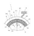
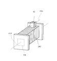
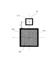
- FIG. 1 It is a block diagram which shows the outline of the structure of the winding short circuit diagnostic apparatus 1 which concerns on embodiment of this invention. It is explanatory drawing which shows the state which looked at the electric motor 2 in the state which the rotor 32 was removed from one side in the axial direction. It is explanatory drawing which shows the outline of the structure of the stator 22. It is a perspective explanatory view which shows the positional relationship between the U-phase winding 24U and the search coil 62 installed on the U-phase winding 24U. It is explanatory drawing which shows the state which looked at the positional relationship between the U-phase winding 24U and the search coil 62 installed on the U-phase winding 24U in the cross section cut by the plane orthogonal to the axes CL1 and CL2.
- the winding short circuit diagnostic apparatus 1 is any one of the three-phase windings 24U, 24V, and 24W described later of the electric motor 2 as a rotating machine (see FIG. 2).
- a voltage oscillating unit 4 that applies an AC voltage between the terminals
- a magnetic field sensor 6 that measures the magnetic field generated in the three-phase windings 24U, 24V, and 24W due to the application of an AC voltage by the voltage oscillating unit 4, and a voltage.
- An A / D conversion unit 8 electrically connected to the oscillation unit 4 and the magnetic field sensor 6 by signal lines L1 and L2, and a diagnostic unit 10 electrically connected to the A / D conversion unit 8 by signal lines L3.
- the diagnostic unit 10 is provided with a display device 12 electrically connected by a signal line L4.
- the electric motor 2 is configured as a general-purpose three-phase induction motor, and mainly includes a stator 22 and a rotor 32 as shown in FIG.
- the stator 22 is formed by laminating thin electromagnetic steel sheets (ferromagnetic materials), and as shown in FIG. 3, the stator 22a is formed in a substantially annular shape, and the yoke 22a is formed from the inner peripheral surface of the yoke 22a. It is equipped with a plurality of teeth 22b extending toward the center of the surface.
- each tooth 22b is directly provided with three-phase windings 24U, 24V, 24W via an insulator (not shown) (so-called centralized winding method). That is, the U-phase winding 24U is wound around 6 of the 18 teeth 22b, the V-phase winding 24V is wound around the other 6 pieces, and the W-phase winding 24W is wound around the remaining 6 pieces. There is.
- the ends of the three-phase windings 24U, 24V, and 24W form a connection terminal 26 that is drawn out as a lead wire to the outside of the motor 2 and connected to a commercial AC power supply.
- stator 22 having the teeth 22b in which the three-phase windings 24U, 24V, and 24W are wound by the centralized winding method is described in the present invention as "concentrated winding is performed on the teeth arranged at substantially equal intervals in the circumferential direction. This is an example of an implementation configuration corresponding to the "stator of the rotating machine".
- the voltage oscillator 4 includes between the U-phase winding 24U and the V-phase winding 24V (hereinafter referred to as “UV-phase”) or the V-phase winding 24V and W among the three-phase windings 24U, 24V, 24W.
- An AC voltage can be applied between the phase windings 24W (hereinafter referred to as "VW phase”) or between the W phase winding 24W and the U phase winding 24U (hereinafter referred to as "WU phase”). It is configured as a function generator that can change the frequency of the applied AC voltage. As shown in FIG.
- the AC voltage applied to each of the UV phase, the VW phase, and the WU phase by the voltage oscillator 4 or the AC current ACI flowing by the AC voltage is A / D converted. After being digitized by the unit 8, it is transmitted to the diagnostic unit 10 via the signal line L3.
- the AC voltage applied by the voltage oscillating unit 4 to each of the UV phase, the VW phase, and the WW phase is 200 volts or less, and the frequency is 60 Hz (or the frequency of the commercial AC voltage oscillating unit). It was set to 1 kHz, which is higher than 200 Hz).
- the power supply can be miniaturized and the electronic circuit of the voltage oscillator 4 can be finished at low cost.
- the winding short circuit diagnostic apparatus 1 itself can be downsized and the cost can be reduced.
- the magnetic field sensor 6 includes a search coil 62 and an amplifier 64 that amplifies the magnitude of the output voltage Vs output from the search coil 62.
- the search coil 62 has a configuration in which the coil is wound for several turns to several tens of turns, thereby outputting an output voltage Vs proportional to the magnitude of the magnetic flux density.
- the output voltage Vs which is an analog signal output from the search coil 62 and amplified by the amplifier 64, is digitized by the A / D converter 8 and then transmitted to the diagnostic unit 10 via the signal line L3.
- the diagnostic unit 10 is configured as a microprocessor centered on a CPU 70 (not shown), and is connected to a ROM 72 (not shown) that stores a processing program in addition to the CPU 70, a RAM 74 that temporarily stores data, and a signal line L3. It is provided with an input port and an output port to which the signal line L4 is connected.
- the output voltage Vs, AC voltage, and AC current ACI from the A / D conversion unit 8 are input to the diagnosis unit 10, and the short-circuit diagnosis results of the three-phase windings 24U, 24V, and 24W are input from the diagnosis unit 10. Is output to the display device 12 via the signal line L4.
- the short-circuit diagnosis of the three-phase windings 24U, 24V, 24W of the electric motor 2 by the winding short-circuit diagnostic device 1 according to the embodiment of the present invention configured in this way will be described.
- the short-circuit diagnosis of the three-phase windings 24U, 24V, and 24W is performed with the rotor 32 removed from the motor 2, that is, with only the centralized stator 22 (see FIG. 2).
- the diagnosis is performed for each tooth 22b in which any one of the three-phase windings 24U, 24V, and 24W is wound, but in the following, for convenience of explanation, the U phase wound in any one tooth 22b.
- a case of diagnosing a short circuit in the winding 24U will be described as an example.
- the magnetic field sensor 6 is installed on any one tooth 22b around which the U-phase winding 24U is wound.
- the magnetic field sensor 6 has the axis CL1 of the search coil 62 on the axis CL2 of the U-phase winding 24U wound around the teeth 22b (the axis CL2 of the teeth 22b).
- the distance from the surface of the U-phase winding 24U of the axis CL1 is set to a predetermined distance h (for example, 5 mm) (see FIG.
- the motor 2 When viewed from one side of the rotor 32) in the axial direction (when FIG. 2 is viewed from the direction perpendicular to the paper surface), the axial line CL1 and the axis CL2 are in an overlapping positional relationship (see FIG. 2). Will be installed.
- the magnetic field sensor 6 is measured on the U-phase winding 24U in which the search coil 62 is wound around the root portion of the teeth 22b (the end portion of the teeth 22b connected to the yoke 22a). It is installed so that it comes to position t 0 .
- an AC voltage 200 V or less
- an AC voltage 200 V or less
- the U-phase winding 24U more specifically, between the U-V phase (or between the W-U phase).
- an alternating current ACI is passed.
- the AC current ACI flowing through the U-phase winding 24U due to the AC voltage is digitized by the A / D conversion unit 8 and then linked to the measured measurement position t 0 and linked to the RAM 74 of the diagnosis unit 10. Is temporarily stored in.
- the RAM 74 that stores the AC current ACI flowing through the U-phase winding 24U due to the AC voltage and the output voltage Vs in association with the measured measurement position t 0 is an example of an embodiment configuration corresponding to the “memory” in the present invention. Is.
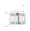
- the closed loop 24Us is induced electromotive force is generated by the magnetic field generated around the U-phase winding 24U by an alternating current ACI is passed, a current flows I S due to the induced electromotive force (see FIG. 8 ).
- a strength H S by the current I S the direction of the magnetic field generated around the U-phase winding 24U by an alternating current ACI reverse A magnetic field is generated.
- the output voltage is output from the search coil 62 Vs is strong magnetic field generated around the U-phase winding 24U by an alternating current ACI of H 0 and the current I S magnetic field intensity H S generated around the closed loop 24Us by The size is proportional to the difference between.
- the induced electromotive force can be expressed as a function of the frequency of the AC voltage applied between the terminals of the U-phase winding 24U, the frequency of the AC voltage applied between the terminals of the U-phase winding 24U should be increased. Accordingly, it is possible to increase intentionally the strength H S of the magnetic field generated around the closed loop 24US. This makes it easy to identify whether or not a short circuit has occurred in the U-phase winding 24U.
- the measured magnetic flux density becomes smaller due to the influence of the inductance component of the U-phase winding 24U. Since the rate of decrease in the magnetic flux density measured at the location where the short circuit S occurs tends to be larger than the rate of decrease in the magnetic flux density measured at the location where the short circuit S does not occur, the U phase As the frequency of the AC voltage applied between the terminals of the winding 24U is increased, the value of the magnetic flux density measured at the location where the short circuit S occurs and the normal location where the short circuit S does not occur. It is possible to make a large difference between the value of the magnetic flux density measured in 1 and the value of the magnetic flux density, which makes it easy to identify whether or not a short circuit has occurred in the U-phase winding 24U.
- a short circuit occurs between the windings in which the U-phase winding 24U is adjacent to the axis CL2 direction of the U-phase winding 24U (the axis CL2 direction of the teeth 22b or the extension direction of the teeth 22b).
- a short circuit occurs between the layers of the U-phase winding 24U
- a new closed loop is generated in the U-phase winding 24U due to the short circuit S, which is caused by the closed loop.
- An induced electromotive force is generated, and an alternating current ACI generates a magnetic field in the direction opposite to the direction of the magnetic field generated around the U-phase winding 24U.
- the U-phase winding 24U when a short circuit occurs between the windings adjacent to the axis CL2 direction of the U-phase winding 24U (the axis CL2 direction of the teeth 22b or the extending direction of the teeth 22b), the U-phase winding 24U than when a short circuit occurs in the layers of windings, the absolute value of the strength H S and the rate of change of the magnetic field of the magnetic field generated around the closed loop 24Us increases.
- the equation (1) is a current Is when a short circuit occurs between windings adjacent to the axis CL2 direction of the U-phase winding 24U (the axis CL2 direction of the teeth 22b or the extending direction of the teeth 22b).
- the formula (2) is a formula for obtaining the current Is when a short circuit occurs between the U-phase windings 24U between the windings, and N> n.
- R is the resistance of the short-circuit S portion
- ⁇ is the angular frequency
- L is the inductance component of the short-circuit S portion
- ⁇ is the magnetic flux passing through the short-circuit S portion
- t is the time
- n and N are the short-circuit S. The number of turns.
- the CPU 70 of the diagnostic unit 10 subsequently determines the magnetic field sensor 6 (based on the relationship between the AC current ACI stored in the RAM 74 and the output voltage Vs.
- the direction of the magnetic field measured by the search coil 62) is determined.
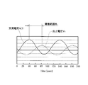
- the phase difference between the AC current ACI and the output voltage Vs is compared, and the direction of the magnetic field is determined based on the phase difference. As shown in FIG. 9, if the phase difference between the AC current ACI and the output voltage Vs is within a predetermined range, it is determined that the direction of the magnetic field is the positive direction, and as shown in FIG.
- the AC current ACI and the output If the phase difference from the voltage Vs is out of the predetermined range, it is determined to be in the negative direction.
- the direction of the magnetic field is defined as the positive direction means that the direction of the magnetic field measured by the magnetic field sensor 6 (search coil 62) is the same as the direction of the magnetic field generated around the U-phase winding 24U.
- the fact that the direction of the magnetic field is negative is defined as the direction of the magnetic field measured by the magnetic field sensor 6 (search coil 62) is opposite to the direction of the magnetic field generated around the U-phase winding 24U. ..
- the CPU 70 of the diagnostic unit 10 that compares the phase difference between the AC current ACI and the output voltage Vs and determines the direction of the magnetic field based on the phase difference is an example of the implementation configuration corresponding to the "processor" in the present invention. is there.
- the mode in which the direction of the magnetic field is positive corresponds to the "first direction” in the present invention, and the mode in which the direction of the magnetic field is negative corresponds to the "second direction” in the present invention. is there.
- the direction of the magnetic field measured by the magnetic field sensor 6 is determined in order to more accurately diagnose whether or not a short circuit has occurred in the U-phase winding 24U. That is, in the centralized winding, due to the configuration in which a ferromagnetic material is used as the material of the teeth 22b, even if a slight short circuit such as a short circuit occurs, the direction is opposite to the direction of the magnetic field created by other parts where the short circuit does not occur. Since a strong magnetic field is generated, the difference between the case where a short circuit occurs and the case where a short circuit does not occur may be unclear only by the strength of the magnetic field (magnitude of output voltage Vs). It may be difficult to determine the occurrence, but by considering the direction of the magnetic field, the difference between the case where a short circuit occurs and the case where a short circuit does not occur becomes clear, so that a short circuit occurs. Can be reliably diagnosed.
- a process of adding a positive with respect to the determined direction of the magnetic field to the stored output voltage Vs is executed. That is, the process of replacing the output voltage Vs previously stored in the RAM 74 (without the positive / negative information added) with the output voltage Vs to which the positive / negative information is added is executed.
- the search coil 62 moves the magnetic field sensor 6 to come to measuring position t 1, the measurement position t 1
- the output voltage Vs is measured in the above, the direction of the magnetic field is determined based on the relationship between the output voltage Vs and the AC current ACI, and the output voltage Vs previously stored in the RAM 74 (without positive / negative information added) is determined.
- the process of replacing with the output voltage Vs to which the positive / negative information is added is executed.
- Such processing is repeatedly executed while moving to the measurement position t L by a predetermined interval d. That is, the position of the search coil 62 is moved from the base of the teeth 22b (the end of the connection of the teeth 22b to the yoke 22a) toward the tip of the teeth 22b (the end of the stator 22 near the center) of the axis CL2 of the teeth 22b.
- the above-mentioned processing (processing from measuring the output voltage Vs to which the positive / negative information is not added until replacing it with the output voltage Vs to which the positive / negative information is added) is executed while moving by a predetermined interval d along the extending direction of. To do.
- the predetermined interval d can be set to a value substantially equal to the distance between the centers of the coils constituting the three-phase windings 24U, 24V, and 24W, for example.
- the output voltage Vs is the first pattern in which all the output voltages Vs are positive, or the second pattern in which the output voltage Vs changes from positive to negative and then changes from negative to positive again. It is determined whether it is the third pattern in which the negative or positive changes from positive or negative to negative or positive, or the fourth pattern in which the output voltage Vs changes in negative.
- the threshold value Vsref1 is set when a short circuit occurs between windings adjacent to the axis CL2 direction of the U-phase winding 24U (the axis CL2 direction of the teeth 22b or the extending direction of the teeth 22b). It is a value set to determine the location where a short circuit occurs, and in the present embodiment, it is configured to be obtained in advance by an experiment or the like and stored in the ROM 72.
- the threshold value Vsref1 is an example of an implementation configuration corresponding to the "second threshold value" in the present invention.
- the threshold value Vsref2 is an example of an implementation configuration corresponding to the "threshold value" in the present invention.
- the U-phase winding 24U at the measurement positions t 0 and t L If the absolute value of the output voltage Vs to which negative information is added is equal to or greater than the threshold Vsref2, or the absolute value of the rate of change CR is greater than or equal to the reference rate of change BCR, the U-phase winding 24U at the measurement positions t 0 and t L. It is determined that a short circuit has occurred between the windings adjacent to the axis CL2 direction (the axis CL2 direction of the teeth 22b or the extending direction of the teeth 22b), and the determination result is transmitted to the display device 12.
- the U phase winding is performed at the measurement positions t 0 and t L. It is determined that a short circuit has occurred between the layers of the wire 24U, and the determination result is transmitted to the display device 12.
- each measurement position t i (i 0 ⁇ L ) for each of the output voltage Vs of the variants of positive and negative information is added occurred in the U-phase winding 24U based on (first, second, third and fourth patterns) Determining the mode of the short circuit, that is, whether a short circuit has occurred between the windings adjacent to the U-phase winding 24U in the axis CL2 direction, or whether a short circuit has occurred between the layers of the winding.
- the CPU 70 is an example of an implementation configuration corresponding to the "processor" in the present invention.
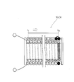
- FIGS. 11 to 11 show the results of experiments in which the above-mentioned first, second, third, and fourth patterns of short-circuit occurrence are diagnosed using the winding short-circuit diagnostic apparatus 1 of the present invention according to the present embodiment. This will be described with reference to 26.
- a solenoid coil in which two layers of windings were wound in a range of 50 mm in the center of the longitudinal direction was used, leaving only 5 mm at both ends in the longitudinal direction of a rectangular body made of iron material having a length of 60 mm, in the longitudinal direction of the solenoid coil.
- a magnetic field sensor 6 is installed so that the search coil 62 is arranged at one end (hereinafter referred to as "measurement start point"), and the magnetic field sensor 6 is set to 2 mm (in the longitudinal direction of the rectangular body) of the solenoid coil.
- the magnetic field was measured by changing the measurement point to the other end in the longitudinal direction of the solenoid coil (hereinafter referred to as “measurement end point”) while shifting the distance between the centers.
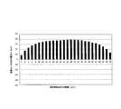
- the solenoid coil SLC1 (FIGS. 11 and 19) having a two-layer winding structure without a short circuit, and the solenoid coil at a position 30 mm from the measurement start point (measurement position t30, FIGS. 12 and 20).
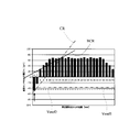
- a two-layer winding structure solenoid coil SLC2 in which a short circuit is generated between windings adjacent to each other in the longitudinal direction of the coil, and windings adjacent to the longitudinal direction of the solenoid coil at the measurement start point (measurement position t 0 , FIGS. 13 and 21).
- a short circuit is generated between the windings of the solenoid coil SLC3 having a two-layer winding structure in which a short circuit is generated between the wires, and the windings adjacent to each other in the longitudinal direction of the solenoid coil at the measurement end point (measurement position t 50 , FIGS. 14 and 22).
- Two-layer winding structure solenoid coil SLC4 two-layer winding structure solenoid coil SLC5 in which a short circuit occurs between the winding layers at a position 37 mm from the measurement start point (FIGS. 15 and 23), measurement end point (FIG. 15 and FIG. 23).
- solenoid coils SLC6 and SCL7 having a two-layer winding structure in which a short circuit is generated between the winding layers (the solenoid coil SCL6 and the solenoid coil SCL7 have the same short circuit location.
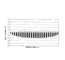
- a solenoid coil SLC8 having a three-layer winding structure in which a short circuit occurs between the winding layers at the measurement start point (measurement position t 0 , FIGS. 18 and 26) is used. And said.
- An alternating current ACI of about 70 mA was applied between the terminals of the solenoid coil (the frequency at this time is 1 kHz).
- the output voltage Vs has a positive value in the entire range from the measurement position t 0 (measurement start point) to the measurement position t 50 (measurement end point). Indicated. As a result, it was confirmed that if the change mode of the output voltage Vs is the first pattern, it can be determined that a short circuit has not occurred in the winding.
- the output voltage Vs becomes negative from the measurement position t 28 (point 28 mm from the measurement start point), and the measurement position t 34 (point 34 mm from the measurement start point). ), The output voltage Vs is positive again.
- the change mode of the output voltage Vs is the second pattern, it can be determined that a short circuit has occurred between the windings adjacent to each other in the longitudinal direction of the windings. It was also confirmed that it was possible to identify that a short circuit occurred at the measurement position t 30 (a point 30 mm from the measurement start point) where the absolute value of the output voltage Vs was equal to or higher than the threshold value Vsref1.
- the output voltage Vs is negative at the measurement position t 0 (measurement start point), and the measurement position t 4 (point 4 mm from the measurement start point).
- output voltage Vs is turned positive, the output voltage Vs to the measurement position t 50 (measurement end point) has remained positive while in.
- the absolute value of the output voltage Vs at the measurement position t 0 (measurement start point) is equal to or higher than the threshold value Vsref2 (dashed line in FIG. 13).
- the absolute value of the slope (change rate CR of output voltage Vs) of the straight line two-dot chain line in FIG.
- the output voltage Vs turns negative at the measurement position t 48 ( 48 mm from the measurement start point) and reaches the measurement position t 50 (measurement end point).
- the output voltage Vs remains negative until.
- the absolute value of the output voltage Vs at the measurement position t 50 (measurement end point) is equal to or higher than the threshold value Vsref2 (dashed line in FIG. 14).
- the absolute value of the slope (change rate CR of output voltage Vs) of the straight line (two-dot chain line in FIG. 14) connecting the positive peak value and the negative peak value of the output voltage Vs is the reference change rate BCR (FIG. 14). 14 solid lines) or more.
- the change mode of the output voltage Vs is the case of the third pattern, and the short circuit is the end portion of the teeth 22b (the extending end portion of the teeth 22b or the end portion of the teeth 22b on the connection portion side to the stator 22).
- the threshold Vsref2 the absolute value of the output voltage Vs is equal to or greater than the threshold Vsref2
- the rate of change CR of the output voltage Vs is greater than or equal to the reference rate of change BCR
- the teeth 22b are adjacent to each other in the longitudinal direction. It was confirmed that it can be determined that a short circuit has occurred between the windings. It was also confirmed that it was possible to identify that a short circuit occurred at the measurement position t 50 (measurement end point) where the absolute value of the output voltage Vs was equal to or higher than the threshold value Vsref1 (broken line in FIG. 14).
- the output voltage Vs turns negative at the measurement position t 38 ( 38 mm from the measurement start point) and reaches the measurement position t 50 (measurement end point).
- the output voltage Vs remains negative until.
- the change mode of the output voltage Vs is the third pattern and the short circuit occurs at a position other than the end of the teeth 22b, that is, at a measurement position other than the measurement positions t 0 and t 50 (measurement end point). If so, it was confirmed that it can be determined that a short circuit has occurred between the layers of the winding. It was also confirmed that it was possible to identify that a short circuit had occurred at the measurement position t 38 (a point 38 mm from the measurement start point) where the output voltage Vs changed from positive to negative.
- the output voltage Vs turns negative at the measurement position t50 (a position 50 mm from the measurement start point).
- the absolute value of the output voltage Vs at the measurement position t 50 (measurement end point) is less than the threshold value Vsref2 (dashed line in FIG. 16).
- the absolute value (change rate CR of output voltage Vs) of the slope of the straight line (two-dot chain line in FIG. 16) connecting the positive peak value and the negative peak value of the output voltage Vs is the reference change rate BCR (FIG. 16). It is less than 16 solid lines).
- the change mode of the output voltage Vs is the case of the third pattern, and the short circuit is the end portion of the teeth 22b (the extending end portion of the teeth 22b or the end portion of the teeth 22b on the connection portion side to the stator 22). If the absolute value of the output voltage Vs is less than the threshold Vsref2, or if the change rate CR of the output voltage Vs is less than the reference change rate BCR, a short circuit occurs between the winding layers. It was confirmed that it can be determined that the voltage is correct. The output voltage Vs is shorted at the measurement position t 50 that switches from positive to negative (measurement end point) was that also confirmed that it is possible to identify the occurring.
- the solenoid coil SLC7 basically causes a short circuit at the same position as the solenoid coil SLC6, but the measurement start point and the measurement end point are opposite to those of the solenoid coil SLC6. .. That is, in the solenoid coil SLC7, the measurement starting point has become a measurement position t 50, the measurement end point is in the measurement position 0.
- the output voltage Vs shows a negative value at the measurement position t 50 (measurement start point), and then the output voltage Vs becomes negative at the measurement position t 48 (point 2 mm from the measurement start point). After turning positive, the output voltage Vs has remained positive until the measurement position t 0 (measurement end point).
- the absolute value of the output voltage Vs at the measurement position t 50 is less than the threshold value Vsref2 (dotted line in FIG. 17).
- the absolute value (change rate CR of output voltage Vs) of the slope of the straight line (two-dot chain line in FIG. 17) connecting the positive peak value and the negative peak value of the output voltage Vs is the reference change rate BCR (FIG. 17). It is less than 17 solid lines).
- the change mode of the output voltage Vs is the case of the third pattern, and the short circuit is the end portion of the teeth 22b (the extending end portion of the teeth 22b or the end portion of the teeth 22b on the connection portion side to the stator 22).
- the solenoid coil SLC8 has a three-layer winding structure unlike the solenoid coils SLC1 to 7 (the solenoid coils SLC1 to 7 have a two-layer winding structure).
- the output voltage Vs has a negative value in the entire range from the measurement position t 0 (measurement start point) to the measurement position t 50 (measurement end point). Indicated.
- the change mode of the output voltage Vs is the fourth pattern, it can be determined that a short circuit has occurred between the winding layers. In this case, the location where the short circuit occurs cannot be specified.
- the direction of the magnetic field measured by the magnetic field sensor 6 (search coil 62) is determined, and the three-phase winding 24U depends on which of the patterns 1 to 4 the change mode of the output voltage Vs in consideration of the direction of the magnetic field corresponds to.
- 24V, 24W is wound around the teeth 22b because it is configured to determine whether a short circuit has occurred between windings adjacent to the teeth 22b in the extending direction or between layers. It is possible to identify how the three-phase windings 24U, 24V, and 24W are short-circuited. As a result, it is possible to obtain mode information that tends to cause a short circuit. Therefore, by feeding back the information to the design stage, measures such as how to wind the winding and the structure of the teeth for winding the winding can be taken. Can be applied. As a result, the short-circuit occurrence rate of the rotating machine such as the electric motor 2 and the generator can be reduced, which can contribute to quality improvement.
- the phase difference between the AC current ACI and the output voltage Vs is compared, and the direction of the magnetic field is determined based on the phase difference, but the present invention is not limited to this.
- the phase difference between the AC voltage and the output voltage Vs may be compared, and the direction of the magnetic field may be determined based on the phase difference.
- the strength of the magnetic field is measured from the root portion of the teeth 22b (the end portion of the teeth 22b connected to the yoke 22a) toward the tip portion of the teeth 22b (the end portion near the center of the stator 22).
- the configuration is such that the direction of the magnetic field is determined, but the present invention is not limited to this.
- the magnetic field is applied from the tip of the tooth 22b (the end near the center of the stator 22) to the root of the tooth 22b (the end of the connection of the tooth 22b to the yoke 22a). It may be configured to measure the strength and perform a process of determining the direction of the magnetic field.
- the change mode of the output voltage Vs is the case of the third pattern, and the short circuit is on the end portion of the teeth 22b (the extending end portion of the teeth 22 or the connection portion side of the teeth 22 to the stator 22). If it occurs at the end), whether or not the absolute value of the output voltage Vs to which negative information is added is equal to or greater than the threshold value Vsref2, and the absolute value of the change rate CR of the output voltage Vs is the reference change.
- the configuration is such that both determination of whether or not the ratio is BCR or higher is performed, but the present invention is not limited to this.
- the configuration may be such that only one is determined. Further, whether or not the absolute value of the output voltage Vs to which negative information is added is equal to or higher than the threshold Vsref2, and whether or not the absolute value of the change rate CR of the output voltage Vs is equal to or higher than the reference change rate BCR.
- both judgments are made, only when both are "OK", a short circuit occurs between the windings adjacent to the axis CL2 direction of the U-phase winding 24U (the axis CL2 direction of the teeth 22b or the extension direction of the teeth 22b). If both are "No", it may be determined that a short circuit has occurred between the layers of the U-phase winding 24U.
- the frequency of the AC voltage applied to each of the UV phase, the VW phase, and the WU phase is set to 1 kHz by the voltage oscillator 4, but the frequency is not limited to this. If the frequency of the AC voltage applied by the voltage oscillating unit 4 between the UV phase, the VW phase, and the WU phase is higher than the frequency of the commercial AC power supply of 60 Hz (or 50 Hz), the frequency will be any value. It may be.
- the voltage oscillating unit 4 sets the AC voltage applied to each of the UV phase, the VW phase, and the WU phase to 200 volts or less, but the present invention is not limited to this.
- the predetermined interval d which is the interval for moving the search coil 62, is set to a value substantially equal to the distance between the centers of the coils constituting the three-phase windings 24U, 24V, and 24W. Not limited to.
- the short circuit of the three-phase windings 24U, 24V, 24W in the stator 22 having the teeth 22b in which the three-phase windings 24U, 24V, 24W are directly wound is diagnosed.
- a configuration for diagnosing a short circuit of the three-phase windings 24U, 24V, 24W in a rotor 32 having a slot in which the three-phase windings 24U, 24V, 24W are directly wound may be used.
- a short circuit of the three-phase windings 24U, 24V, and 24W may be diagnosed with the stator 22 removed from the motor 2 and only the rotor 32.
- the present embodiment shows an example of a mode for carrying out the present invention. Therefore, the present invention is not limited to the configuration of the present embodiment.
- the correspondence between each component of the present embodiment and each component of the present invention is shown below.
- Winding short circuit diagnostic device (winding short circuit diagnostic device) 2 Electric motor (rotating machine) 4 Voltage oscillator (voltage oscillator) 6 Magnetic field sensor (magnetic field sensor) 8 A / D conversion unit 10 Diagnosis unit 22 Stator (stator) 22a York 22b Teeth (Teeth) 24U U phase winding (winding) 24Us Closed Loop 24V V-Phase Winding 24W W phase winding (winding) 26 Connection terminal 32 Rotor (rotor) 62 Search coil (search coil) 64 Amplifier 70 CPU (Processor) 72 ROM 74 RAM (memory) 106 Magnetic field sensor (Magnetic field sensor) ACI alternating current (alternating current) L1 signal line L2 signal line L3 signal line L4 signal line Vs output voltage (output voltage) CL1 axis CL2 axis H 0 field strength H s magnetic field intensity I s current S short t 0 the measurement position t L measurement position t i measured position d predetermined distance h
Abstract
[Problem] To easily identify a mode of short circuit in a winding in a stator or a rotor of a rotary machine in which concentrated winding has been performed on teeth. [Solution] A magnetic field generated in three-phase windings 24U, 24V, 24W wound around each of teeth 22b is measured along the extension direction of said teeth 22b at each prescribed interval d by using a magnetic field sensor 6, the orientation of the magnetic field measured by the magnetic field sensor 6 is determined by comparing the phase difference between an alternating current flowing in the three-phase windings 24U, 24V, 24W and an output voltage Vs at each measurement position ti, and it is assessed, on the basis of a change mode of the output voltage Vs for which the orientation of the magnetic field has been taken into account, whether, in the three-phase windings 24U, 24V, 24W: a short circuit has occurred between windings adjacent in the extension direction of the teeth 22b; or, alternatively, a short circuit has occurred between layers. The mode of short circuit in the three-phase windings 24U, 24V, 24W wound around the teeth 22b is thereby easily identified.
Description
本発明は、円周方向に略等間隔で複数配置されたティースに集中巻を施した回転機の固定子または回転子における巻線の短絡を診断する巻線短絡診断装置および巻線短絡診断方法に関する。
The present invention is a winding short-circuit diagnostic device and a winding short-circuit diagnostic method for diagnosing a short-circuit of a winding in a stator or a rotor of a rotor in which a plurality of teeth arranged at substantially equal intervals in the circumferential direction are centrally wound. Regarding.
特開平2009-115505号公報(特許文献1)には、電動機や発電機のような回転機の内部の巻線のうち任意の相の巻線の端子間にインパルス電圧を印加すると共に、当該インパルス電圧の印加によって巻線の端子間に発生する振動電圧の波形を検出し、当該検出した振動電圧の波形を予め作成しておいた正常巻線(短絡が発生していない巻線)の振動電圧の波形と比較することにより、巻線の短絡発生の有無を診断する巻線短絡診断装置が記載されている。
In Japanese Patent Application Laid-Open No. 2009-115505 (Patent Document 1), an impulse voltage is applied between the terminals of windings of any phase among the windings inside a rotating machine such as an electric motor or a generator, and the impulse is applied. The waveform of the vibration voltage generated between the terminals of the winding due to the application of voltage is detected, and the waveform of the detected vibration voltage is created in advance. The vibration voltage of the normal winding (winding without short circuit). A winding short circuit diagnostic device for diagnosing the presence or absence of a short circuit in a winding is described by comparing with the waveform of.
当該巻線短絡診断装置では、どの相の巻線で短絡が発生しているのか、例えば、三相誘導電動機であれば、短絡がU相で発生しているのか、それともV相やW相で発生しているのかを特定することができる。
In the winding short-circuit diagnostic device, which phase of the winding is the short-circuit, for example, in the case of a three-phase induction motor, is the short-circuit in the U phase, or in the V phase or W phase? It is possible to identify whether it is occurring.
ところで、電動機や発電機のような回転機の内部の巻線がどのような態様で短絡しているのかを特定できれば、当該短絡の態様情報を設計段階へフィードバックすることで、巻線の巻き方や巻線を巻くためのティースの構造などについて対策を施すことができるため、電動機や発電機といった回転機の短絡発生割合を低下させることにつながり、大きなメリットとなる。ここで、巻線の短絡の態様としては、例えば、ティースの長さ方向に隣接する巻線間において短絡が発生する態様や、巻線の層間において短絡が発生する態様が考えられる。
By the way, if it is possible to identify how the windings inside a rotating machine such as an electric motor or a generator are short-circuited, how to wind the windings by feeding back the mode information of the short-circuit to the design stage. Since it is possible to take measures for the structure of the teeth for winding the winding and the winding, it leads to a reduction in the short-circuit occurrence rate of the rotating machine such as an electric motor and a generator, which is a great merit. Here, as a mode of short-circuiting the windings, for example, a mode in which a short-circuit occurs between windings adjacent in the length direction of the teeth and a mode in which a short-circuit occurs between layers of the windings can be considered.
なお、出願人も、電動機や発電機といった回転機の短絡発生割合を低下させるとう観点から、特許第6404424号公報(特許文献2)において、ティースに集中巻を施した回転機の固定子または回転子における巻線のどのあたりで短絡が発生しているのかを特定することができる巻線短絡診断装置を提案している。
In addition, from the viewpoint of reducing the short-circuit occurrence rate of rotors such as electric motors and generators, the applicant also referred to Patent No. 64044424 (Patent Document 2) as a stator or rotation of a rotor in which teeth are centrally wound. We are proposing a winding short circuit diagnostic device that can identify where the short circuit occurs in the winding in the child.
本発明は、上記に鑑みてなされたものであり、ティースに集中巻を施した回転機の固定子または回転子における巻線の短絡の態様を簡易に特定することができる巻線短絡診断装置および巻線短絡診断方法を提供することを主目的とする。
The present invention has been made in view of the above, and is a winding short-circuit diagnostic apparatus and a winding short-circuit diagnostic apparatus capable of easily specifying a mode of short-circuiting of a winding in a stator or a rotor of a rotating machine in which a tooth is centrally wound. The main purpose is to provide a winding short circuit diagnostic method.
本発明に係る巻線短絡診断装置の好ましい形態によれば、円周方向に略等間隔で複数配置されたティースに集中巻を施した回転機の固定子または回転子における巻線の短絡を診断する巻線短絡診断装置が構成される。当該巻線短絡診断装置は、電圧発振部と、磁界センサと、メモリと、プロセッサと、を備えている。電圧発振部は、巻線の端子間に交流電圧を印加するように構成されている。磁界センサは、交流電圧の印加に応じてティース毎に巻かれた巻線に生じる磁界の強さをティースの延出方向に沿って所定間隔毎に計測する。メモリは、交流電圧または当該交流電圧に起因して巻線に流れる交流電流と磁界の強さとを記憶する。プロセッサは、交流電圧または交流電流と磁界の強さとに基づいてメモリに記憶された磁界の向きを計測位置毎に決定する。また、プロセッサは、決定した磁界の向きの全てが第1方向である第1パターンの場合には、巻線には短絡が発生していないと判定し、磁界の向きが第1方向から当該第1方向とは反対方向である第2方向に変化した後、当該第2方向から第1方向に変化する第2パターンの場合には、ティースの延出方向に隣接する巻線間において短絡が発生したと判定し、磁界の向きが第1方向または第2方向から第2方向または第1方向に変化した後、当該第2方向または第1方向のまま推移する第3パターンの場合、および、磁界の向きが全て第2方向である第4パターンの場合には、巻線の層間において短絡が発生したと判定する。
According to a preferred embodiment of the winding short-circuit diagnostic apparatus according to the present invention, a short-circuit of a winding in a stator or a rotor of a rotor in which a plurality of teeth arranged at substantially equal intervals in the circumferential direction are centrally wound is diagnosed. A winding short circuit diagnostic device is configured. The winding short-circuit diagnostic device includes a voltage oscillator, a magnetic field sensor, a memory, and a processor. The voltage oscillator is configured to apply an AC voltage between the terminals of the winding. The magnetic field sensor measures the strength of the magnetic field generated in the winding wound for each tooth in response to the application of an AC voltage at predetermined intervals along the extending direction of the tooth. The memory stores the AC voltage or the AC current flowing through the winding due to the AC voltage and the strength of the magnetic field. The processor determines the direction of the magnetic field stored in the memory for each measurement position based on the AC voltage or AC current and the strength of the magnetic field. Further, the processor determines that no short circuit has occurred in the winding in the case of the first pattern in which all the determined magnetic field directions are the first direction, and the magnetic field direction is from the first direction to the first pattern. In the case of the second pattern, which changes from the second direction to the first direction after changing in the second direction opposite to the one direction, a short circuit occurs between the windings adjacent to the extending direction of the teeth. In the case of the third pattern in which the direction of the magnetic field changes from the first direction or the second direction to the second direction or the first direction and then changes in the second direction or the first direction, and the magnetic field. In the case of the fourth pattern in which all the directions of are the second direction, it is determined that a short circuit has occurred between the layers of the winding.
ここで、本願発明における「磁界の強さ」とは、ティース毎に巻かれた巻線に生じる磁束密度の大きさ、あるいは、当該磁束密度の大きさに比例した電圧がこれに該当する。
Here, the "magnetic field strength" in the present invention corresponds to the magnitude of the magnetic flux density generated in the winding wound for each tooth, or the voltage proportional to the magnitude of the magnetic flux density.
本発明者は、ティースに集中巻を施した回転機の固定子または回転子における巻線の短絡について鋭意研究を行った結果、ティースの延出方向に沿って所定間隔毎に求めた磁界の強さおよび磁界の向きの変化のパターンが、巻線の短絡の態様によって異なることを見出した。このような研究結果を踏まえて、本発明では、第1パターンの場合には、巻線に短絡が発生していないと判定し、第2パターンの場合には、ティースの延出方向に隣接する巻線間において短絡が発生したと判定し、第3パターンおよび第4パターンの場合には、巻線の層間において短絡が発生したと判定する構成であるため、巻線の短絡の態様を簡易に特定することができる。これにより、短絡の態様情報を設計段階へフィードバックすることができ、巻線の巻き方や巻線を巻くためのティースの構造などについての対策を施すことができる。この結果、電動機や発電機といった回転機の短絡発生割合を低下させることにつながり、品質向上に寄与し得る。
As a result of diligent research on the short circuit of the winding in the stator or rotor of the rotor in which the teeth are centrally wound, the present inventor has obtained the strength of the magnetic field at predetermined intervals along the extending direction of the teeth. It has been found that the pattern of change in the direction of the coil and the magnetic field differs depending on the mode of short circuit of the winding. Based on such research results, in the present invention, in the case of the first pattern, it is determined that a short circuit has not occurred in the winding, and in the case of the second pattern, it is adjacent to the extending direction of the teeth. Since it is determined that a short circuit has occurred between the windings, and in the case of the third pattern and the fourth pattern, it is determined that a short circuit has occurred between the layers of the windings, the mode of the short circuit of the windings can be simplified. Can be identified. As a result, the short-circuit mode information can be fed back to the design stage, and measures can be taken regarding the winding method of the winding and the structure of the teeth for winding the winding. As a result, it is possible to reduce the short-circuit occurrence rate of rotating machines such as electric motors and generators, which can contribute to quality improvement.
本発明に係る巻線短絡診断装置の更なる形態によれば、プロセッサは、第3パターンの場合であって、第1方向または第2方向から第2方向または第1方向への磁界の向きの変化がティースの延出方向の端部において生じている場合には、第2方向の磁界の強さと閾値とを比較し、当該磁界の強さが閾値以上である場合、および/または、当該磁界の向きが第1方向または第2方向から第2方向または第1方向に変化する際の磁界の強さの変化割合の絶対値と基準変化割合とを比較し、当該変化割合の絶対値が当該基準変化割合以上である場合には、ティースの長手向に隣接する巻線間において短絡が発生したと判定し、磁界の強さが閾値未満である場合、および/または、変化割合の絶対値が基準変化割合未満である場合には、巻線の層間において短絡が発生したと判定する。
According to a further embodiment of the winding short circuit diagnostic apparatus according to the present invention, the processor is the case of the third pattern, in which the direction of the magnetic field from the first direction or the second direction to the second direction or the first direction. If the change occurs at the end of the teeth in the extending direction, compare the strength of the magnetic field in the second direction with the threshold, and if the strength of the magnetic field is greater than or equal to the threshold, and / or the magnetic field. The absolute value of the change rate of the magnetic field strength when the direction of is changed from the first direction or the second direction to the second direction or the first direction is compared with the reference change rate, and the absolute value of the change rate is the relevant value. If it is greater than or equal to the reference rate of change, it is determined that a short circuit has occurred between the windings adjacent to the longitudinal direction of the teeth, and if the strength of the magnetic field is less than the threshold value, and / or the absolute value of the rate of change is If it is less than the reference change rate, it is determined that a short circuit has occurred between the layers of the winding.
本形態によれば、ティースの延出方向の端部であって、磁界の計測開始位置または計測終了位置において発生した巻線の短絡が、ティースの延出方向に隣接する巻線間の短絡か、巻線の層間の短絡か、を判定することができる。ティースの延出方向に隣接する巻線間の短絡であっても、ティースの延出方向の端部であって、磁界の計測開始位置または計測終了位置において巻線の短絡が生じている場合には、磁界の向きが第1方向または第2方向から第2方向または第1方向へ変化したままとなるため、当該第2方向の磁界の強さを予め設定した閾値と比較することによって、および/または、磁界の向きが第1方向または第2方向から第2方向または第1方向へと変化する際の磁界の強さの変化割合の絶対値を予め設定した基準変化割合と比較することによって、発生した当該短絡がティースの延出方向に隣接する巻線間の短絡か、巻線の層間の短絡か、を判別するのである。ここで、同じ条件であれば、巻線の層間での短絡の方がティースの延出方向に隣接する巻線間での短絡よりも、磁界の強さが弱い、あるいは、磁界の強さの変化割合の絶対値が小さいことから、巻線の層間で短絡が発生した場合の磁界の強さ、あるいは、磁界の強さの変化割合の絶対値と、ティースの延出方向に隣接する巻線間で短絡が発生した場合の磁界の強さ、あるいは、磁界の強さの変化割合の絶対値と、の間の適切な値に閾値または基準変化割合を設定することによって、ティースの延出方向に隣接する巻線間の短絡と、巻線の層間の短絡と、の判別が可能となる。
According to this embodiment, is the short circuit of the winding generated at the measurement start position or the measurement end position of the magnetic field at the end in the extending direction of the tooth a short circuit between the windings adjacent to the extending direction of the tooth? , It can be determined whether it is a short circuit between the winding layers. Even if there is a short circuit between windings adjacent in the extending direction of the teeth, if the windings are short-circuited at the end of the extending direction of the teeth at the measurement start position or measurement end position of the magnetic field. By comparing the strength of the magnetic field in the second direction with a preset threshold, because the direction of the magnetic field remains changing from the first direction or the second direction to the second or the first direction. / Or by comparing the absolute value of the rate of change in the strength of the magnetic field when the direction of the magnetic field changes from the first direction or the second direction to the second direction or the first direction with a preset reference rate of change. , It is determined whether the short circuit generated is a short circuit between windings adjacent to each other in the extending direction of the teeth or a short circuit between the windings. Here, under the same conditions, the short circuit between the winding layers has a weaker magnetic field strength or the magnetic field strength than the short circuit between the windings adjacent to each other in the extending direction of the teeth. Since the absolute value of the rate of change is small, the strength of the magnetic field when a short circuit occurs between the layers of the winding, or the absolute value of the rate of change of the strength of the magnetic field and the winding adjacent to the extension direction of the teeth. By setting a threshold value or a reference change rate to an appropriate value between the absolute value of the magnetic field strength when a short circuit occurs between them or the change rate of the magnetic field strength, the extension direction of the teeth. It is possible to distinguish between a short circuit between windings adjacent to the coil and a short circuit between the windings.
本発明に係る巻線短絡診断装置の更なる形態によれば、メモリは、磁界の強さを計測位置に紐づけて記憶可能である。そして、プロセッサは、巻線の層間において短絡が発生していると判定した場合、磁界の向きが最初に第2方向となった計測位置において巻線に短絡が発生していると判定する。
According to a further form of the winding short circuit diagnostic apparatus according to the present invention, the memory can store the strength of the magnetic field in association with the measurement position. Then, when the processor determines that a short circuit has occurred between the layers of the winding, it determines that the winding has a short circuit at the measurement position where the direction of the magnetic field is first in the second direction.
本形態によれば、巻線の層間において短絡が発生している場合において、ティースに巻かれた巻線のどのあたりで短絡が発生しているのかを特定することができる。これにより、短絡が発生しやすい傾向にある箇所の情報を取得し得るため、当該情報を設計段階へフィードバックすることによって、短絡が起こりやすい箇所での構造的もしくは強度的な対策を施すことができ、電動機や発電機といった回転機の短絡発生割合を低下させることにつながり、品質向上に寄与し得る。
According to this embodiment, when a short circuit occurs between the layers of the winding, it is possible to specify where in the winding wound around the tooth the short circuit occurs. As a result, it is possible to acquire information on locations where short circuits are likely to occur. Therefore, by feeding back the information to the design stage, it is possible to take structural or strong measures at locations where short circuits are likely to occur. , It leads to the reduction of the short circuit occurrence rate of rotating machines such as electric motors and generators, and can contribute to quality improvement.
本発明に係る巻線短絡診断装置の更なる形態によれば、メモリは、磁界の強さを計測位置に紐づけて記憶可能である。そして、プロセッサは、ティースの長手向に隣接する巻線間において短絡が発生していると判定した場合、第2方向の磁界の強さと第2閾値とを比較し、最初に第2閾値以上であると判定された磁界の強さに紐づけされた計測位置において巻線に短絡が発生していると判定する。
According to a further form of the winding short circuit diagnostic apparatus according to the present invention, the memory can store the strength of the magnetic field in association with the measurement position. Then, when the processor determines that a short circuit has occurred between the windings adjacent to the longitudinal direction of the teeth, the processor compares the strength of the magnetic field in the second direction with the second threshold value, and first sets the second threshold value or higher. It is determined that a short circuit has occurred in the winding at the measurement position associated with the strength of the magnetic field determined to be present.
本形態によれば、ティースの長手向に隣接する巻線間に短絡が発生している場合において、ティースに巻かれた巻線のどのあたりで短絡が発生しているのかを特定することができる。これにより、短絡が発生しやすい傾向にある箇所の情報を取得し得るため、当該情報を設計段階へフィードバックすることによって、短絡が起こりやすい箇所での構造的もしくは強度的な対策を施すことができ、電動機や発電機といった回転機の短絡発生割合を低下させることにつながり、品質向上に寄与し得る。
According to this embodiment, when a short circuit occurs between windings adjacent to each other in the longitudinal direction of the teeth, it is possible to specify where in the windings wound around the teeth the short circuit occurs. .. As a result, it is possible to acquire information on locations where short circuits are likely to occur. Therefore, by feeding back the information to the design stage, it is possible to take structural or strong measures at locations where short circuits are likely to occur. , It leads to the reduction of the short circuit occurrence rate of rotating machines such as electric motors and generators, and can contribute to quality improvement.
本発明に係る巻線短絡診断装置の更なる形態によれば、電圧発振部は、商用周波数よりも高い周波数を有する交流電圧を巻線の端子間に印加する。
According to a further form of the winding short circuit diagnostic apparatus according to the present invention, the voltage oscillator applies an AC voltage having a frequency higher than the commercial frequency between the terminals of the winding.
本発明者らは、電圧発振部によって印加する交流電圧の周波数を上げていくことに伴って、巻線のインダクタンス成分の影響によって,計測される磁束密度は小さくなる一方で、巻線のうち短絡が発生している箇所において計測される磁束密度の低下割合は、短絡が発生していない箇所において計測される磁束密度の低下割合に対して大きくなる傾向にあることを見出した。即ち、電圧発振部によって印加する交流電圧の周波数を上げていくと、巻線において短絡が発生していない正常な箇所において計測される磁束密度の値と、短絡が発生している箇所において計測される磁束密度の値と、の間に大きな差異が生じることを見出した。このような研究結果を踏まえて、本実施形態では、巻線の端子間に印加する交流電圧の周波数を商用周波数よりも高い周波数とする構成であるため、短絡が発生の有無を特定し易くなる。
As the frequency of the AC voltage applied by the voltage oscillating unit is increased, the present inventors reduce the measured magnetic flux density due to the influence of the inductance component of the winding, while short-circuiting the winding. It was found that the rate of decrease in the magnetic flux density measured at the location where the short circuit occurs tends to be larger than the rate of decrease in the magnetic flux density measured at the location where the short circuit does not occur. That is, when the frequency of the AC voltage applied by the voltage oscillating unit is increased, the value of the magnetic flux density measured at the normal place where the short circuit does not occur in the winding and the value measured at the place where the short circuit occurs. It was found that there is a large difference between the value of the magnetic flux density and the value of the magnetic flux density. Based on these research results, in the present embodiment, since the frequency of the AC voltage applied between the terminals of the winding is set to a frequency higher than the commercial frequency, it becomes easy to identify the presence or absence of a short circuit. ..
本発明に係る巻線短絡診断装置の更なる形態によれば、電圧発振部は、200ボルト以下の交流電圧を巻線の端子間に印加する。
According to a further form of the winding short circuit diagnostic apparatus according to the present invention, the voltage oscillator applies an AC voltage of 200 volts or less between the terminals of the winding.
本形態によれば、電圧発振部に供給する電源を小型化することができると共に、電圧発振部の電子回路を安価に仕上げることができる。これにより、巻線短絡診断装置自体の小型化およびコスト低減を図ることができる。
According to this embodiment, the power supply supplied to the voltage oscillator can be miniaturized, and the electronic circuit of the voltage oscillator can be finished at low cost. As a result, the winding short circuit diagnostic apparatus itself can be downsized and the cost can be reduced.
本発明に係る巻線短絡診断装置の更なる形態によれば、磁界センサは、磁界の強さを計測するサーチコイルを有している。そして、当該磁界センサは、磁界の強さを計測する際、サーチコイルの軸線方向がティースに巻かれた巻線の軸線方向と平行になるように配置されている。
According to a further form of the winding short circuit diagnostic apparatus according to the present invention, the magnetic field sensor has a search coil for measuring the strength of the magnetic field. When measuring the strength of the magnetic field, the magnetic field sensor is arranged so that the axial direction of the search coil is parallel to the axial direction of the winding wound on the tooth.
本形態によれば、電圧発振部により巻線の端子間に印加された交流電圧によって当該巻線に発生する磁界の強さを精度よく計測することができる。
According to this embodiment, it is possible to accurately measure the strength of the magnetic field generated in the winding by the AC voltage applied between the terminals of the winding by the voltage oscillator.
本発明に係る巻線短絡診断装置の更なる形態によれば、磁界センサは、磁界の強さを計測するサーチコイルを有している。そして、当該磁界センサは、磁界の強さを計測する際、固定子または回転子の軸線方向の一方側から見たときの仮想投影面上におけるサーチコイルの軸線が、ティースに巻かれた巻線の軸線に重なるように配置されている。
According to a further form of the winding short circuit diagnostic apparatus according to the present invention, the magnetic field sensor has a search coil for measuring the strength of the magnetic field. Then, when the magnetic field sensor measures the strength of the magnetic field, the axis of the search coil on the virtual projection plane when viewed from one side in the axial direction of the stator or rotor is wound around the teeth. It is arranged so as to overlap the axis of.
本形態によれば、磁界センサのサーチコイルの軸線をティースに巻かれた巻線の軸線に一致させた状態で磁界の強さを計測する構成であるため、ティースに巻かれた巻線の側縁、換言すれば、ティースに巻かれた巻線のうち軸線から径方向外方向に離れた位置にある部分によって作られる磁界の影響を小さく抑えることができる。これにより、より正確に巻線の短絡発生の有無を診断することができる。
According to this embodiment, since the magnetic field strength is measured in a state where the axis of the search coil of the magnetic field sensor is aligned with the axis of the winding wound around the tooth, the side of the winding wound around the tooth is measured. The influence of the magnetic field generated by the edge, in other words, the portion of the winding wound around the tooth that is radially outwardly separated from the axis can be suppressed. This makes it possible to more accurately diagnose the presence or absence of a short circuit in the winding.
本発明に係る巻線短絡診断方法の好ましい形態によれば、円周方向に略等間隔で複数配置されたティースに集中巻を施した回転機の固定子または回転子における当該巻線の短絡を診断する巻線短絡診断方法が構成される。当該巻線短絡診断方法は、(a)ティース毎に巻かれた巻線の端子間に交流電圧を印加し、(b)交流電圧の印加に応じてティース毎に巻かれた巻線に生じる磁界の強さを、ティースの延出方向に沿って所定間隔毎に計測し、(c)交流電圧または当該交流電圧に起因して巻線に流れる交流電流と、計測された磁界の強さと、を記憶し、(d)交流電圧または交流電流と、磁界の強さと、に基づいて、記憶された所定間隔毎の磁界の向きを決定し、(e)決定した磁界の向きの全てが第1方向である第1パターンの場合には、巻線には短絡が発生していないと判定し、メモリに記憶した磁界の向きが第1方向から当該第1方向とは反対方向である第2方向に変化した後、当該第2方向から第1方向に変化する第2パターンの場合には、ティースの延出方向に隣接する巻線間において短絡が発生していると判定し、メモリに記憶した磁界の向きが第1方向または第2方向から第2方向または第1方向に変化した後、当該第2方向または第1方向のまま推移する第3パターンの場合、および、磁界の向きの全てが第2方向である第4パターンの場合には、巻線の層間において短絡が発生していると判定する。
According to a preferred embodiment of the winding short-circuit diagnostic method according to the present invention, a short-circuit of the winding in a stator or a rotor of a rotor in which a plurality of teeth arranged at substantially equal intervals in the circumferential direction are centrally wound. A winding short circuit diagnostic method for diagnosis is configured. In the winding short circuit diagnosis method, (a) an AC voltage is applied between the terminals of the winding wound for each tooth, and (b) a magnetic field generated in the winding wound for each tooth in response to the application of the AC voltage. The strength of is measured at predetermined intervals along the extension direction of the teeth, and (c) the AC voltage or the AC current flowing through the winding due to the AC voltage and the measured magnetic field strength are measured. Stored, (d) the direction of the stored magnetic field at predetermined intervals is determined based on (d) the AC voltage or AC current, and the strength of the magnetic field, and (e) all the determined magnetic field directions are the first directions. In the case of the first pattern, it is determined that no short circuit has occurred in the winding, and the direction of the magnetic field stored in the memory changes from the first direction to the second direction opposite to the first direction. In the case of the second pattern that changes from the second direction to the first direction after the change, it is determined that a short circuit has occurred between the windings adjacent to the extending direction of the teeth, and the magnetic field stored in the memory. In the case of the third pattern in which the direction of is changed from the first direction or the second direction to the second direction or the first direction and then changes in the second direction or the first direction, and all the directions of the magnetic field are the first. In the case of the fourth pattern having two directions, it is determined that a short circuit has occurred between the layers of the winding.
ここで、本願発明における「磁界の強さ」とは、ティース毎に巻かれた巻線に生じる磁束密度の大きさ、あるいは、当該磁束密度の大きさに比例した電圧がこれに該当する。
Here, the "magnetic field strength" in the present invention corresponds to the magnitude of the magnetic flux density generated in the winding wound for each tooth, or the voltage proportional to the magnitude of the magnetic flux density.
本発明者は、ティースに集中巻を施した回転機の固定子または回転子における巻線の短絡について鋭意研究を行った結果、ティースの延出方向に沿って所定間隔毎に求めた磁界の強さおよび磁界の向きの変化のパターンが、巻線の短絡の態様によって異なることを見出した。このような研究結果を踏まえて、本発明では、第1パターンの場合には、巻線に短絡が発生していないと判定し、第2パターンの場合には、ティースの延出方向に隣接する巻線間において短絡が発生したと判定し、第3パターンおよび第4パターンの場合には、巻線の層間において短絡が発生したと判定する構成であるため、巻線の短絡の態様を簡易に特定することができる。これにより、短絡の態様情報を設計段階へフィードバックすることができ、巻線の巻き方や巻線を巻くためのティースの構造などについての対策を施すことができる。この結果、電動機や発電機といった回転機の短絡発生割合を低下させることにつながり、品質向上に寄与し得る。
As a result of diligent research on the short circuit of the winding in the stator or rotor of the rotor in which the teeth are centrally wound, the present inventor has obtained the strength of the magnetic field at predetermined intervals along the extending direction of the teeth. It has been found that the pattern of change in the direction of the coil and the magnetic field differs depending on the mode of short circuit of the winding. Based on such research results, in the present invention, in the case of the first pattern, it is determined that a short circuit has not occurred in the winding, and in the case of the second pattern, it is adjacent to the extending direction of the teeth. Since it is determined that a short circuit has occurred between the windings, and in the case of the third pattern and the fourth pattern, it is determined that a short circuit has occurred between the layers of the windings, the mode of the short circuit of the windings can be simplified. Can be identified. As a result, the short-circuit mode information can be fed back to the design stage, and measures can be taken regarding the winding method of the winding and the structure of the teeth for winding the winding. As a result, it is possible to reduce the short-circuit occurrence rate of rotating machines such as electric motors and generators, which can contribute to quality improvement.
本発明に係る巻線短絡診断方法の更なる形態によれば、ステップ(e)は、第3パターンの場合であって、第1方向または第2方向から第2方向または第1方向への磁界の向きの変化がティースの延出方向の端部において生じている場合には、当該第2方向の磁界の強さと閾値とを比較し、当該磁界の強さが閾値以上である場合、および/または、磁界の向きが第1方向または第2方向から第2方向または第1方向に変化する際の磁界の強さの変化割合の絶対値と基準変化割合とを比較し、当該変化割合の絶対値が当該基準変化割合以上である場合には、ティースの長手向に隣接する巻線間において短絡が発生したと判定し、磁界の強さが閾値未満である場合、および/または、変化割合の絶対値が基準変化割合未満である場合には、巻線の層間において短絡が発生したと判定するステップを含んでいる。
According to a further embodiment of the winding short circuit diagnostic method according to the present invention, the step (e) is the case of the third pattern, and the magnetic field from the first direction or the second direction to the second direction or the first direction. If the change in direction occurs at the end of the teeth in the extending direction, the strength of the magnetic field in the second direction is compared with the threshold value, and if the strength of the magnetic field is greater than or equal to the threshold value, and / Alternatively, the absolute value of the change rate of the magnetic field strength when the direction of the magnetic field changes from the first direction or the second direction to the second direction or the first direction is compared with the reference change rate, and the absolute value of the change rate is absolute. If the value is greater than or equal to the reference rate of change, it is determined that a short circuit has occurred between the windings adjacent to the longitudinal direction of the teeth, and if the strength of the magnetic field is less than the threshold value, and / or the rate of change. If the absolute value is less than the reference rate of change, it includes a step of determining that a short circuit has occurred between the layers of the winding.
本形態によれば、ティースの延出方向の端部であって、磁界の計測開始位置または計測終了位置において発生した巻線の短絡が、ティースの延出方向に隣接する巻線間の短絡か、巻線の層間の短絡か、を判定することができる。ティースの延出方向に隣接する巻線間の短絡であっても、ティースの延出方向の端部であって、磁界の計測開始位置または計測終了位置において巻線の短絡が生じている場合には、磁界の向きが第1方向または第2方向から第2方向または第1方向へ変化したままとなるため、当該第2方向の磁界の強さを予め設定した閾値と比較することによって、および/または、磁界の向きが第1方向または第2方向から第2方向または第1方向へと変化する際の磁界の強さの変化割合の絶対値を予め設定した基準変化割合と比較することによって、発生した当該短絡がティースの延出方向に隣接する巻線間の短絡か、巻線の層間の短絡か、を判別するのである。ここで、同じ条件であれば、巻線の層間での短絡の方がティースの延出方向に隣接する巻線間での短絡よりも、磁界の強さが弱い、あるいは、磁界の強さの変化割合の絶対値が小さいことから、巻線の層間で短絡が発生した場合の磁界の強さ、あるいは、磁界の強さの変化割合の絶対値と、ティースの延出方向に隣接する巻線間で短絡が発生した場合の磁界の強さ、あるいは、磁界の強さの変化割合の絶対値と、の間の適切な値に閾値または基準変化割合を設定することによって、ティースの延出方向に隣接する巻線間の短絡と、巻線の層間の短絡と、の判別が可能となる。
According to this embodiment, is the short circuit of the winding generated at the measurement start position or the measurement end position of the magnetic field at the end in the extending direction of the tooth a short circuit between the windings adjacent to the extending direction of the tooth? , It can be determined whether it is a short circuit between the winding layers. Even if there is a short circuit between windings adjacent in the extending direction of the teeth, if the windings are short-circuited at the end of the extending direction of the teeth at the measurement start position or measurement end position of the magnetic field. By comparing the strength of the magnetic field in the second direction with a preset threshold, because the direction of the magnetic field remains changing from the first direction or the second direction to the second or the first direction. / Or by comparing the absolute value of the rate of change in the strength of the magnetic field when the direction of the magnetic field changes from the first direction or the second direction to the second direction or the first direction with a preset reference rate of change. , It is determined whether the short circuit generated is a short circuit between windings adjacent to each other in the extending direction of the teeth or a short circuit between the windings. Here, under the same conditions, the short circuit between the winding layers has a weaker magnetic field strength or the magnetic field strength than the short circuit between the windings adjacent to each other in the extending direction of the teeth. Since the absolute value of the rate of change is small, the strength of the magnetic field when a short circuit occurs between the layers of the winding, or the absolute value of the rate of change of the strength of the magnetic field and the winding adjacent to the extension direction of the teeth. By setting a threshold value or a reference change rate to an appropriate value between the absolute value of the magnetic field strength when a short circuit occurs between them or the change rate of the magnetic field strength, the extension direction of the teeth. It is possible to distinguish between a short circuit between windings adjacent to the coil and a short circuit between the windings.
本発明によれば、ティースに集中巻を施した回転機の固定子または回転子における巻線の短絡の態様を特定することができる。
According to the present invention, it is possible to specify the mode of short-circuiting of the winding in the stator or rotor of the rotating machine in which the teeth are centrally wound.
次に、本発明を実施するための最良の形態を実施例を用いて説明する。
Next, the best mode for carrying out the present invention will be described with reference to examples.
本発明の実施の形態に係る巻線短絡診断装置1は、図1に示すように、回転機としての電動機2(図2参照)の後述する三相巻線24U,24V,24Wのいずれかの端子間に交流電圧を印加する電圧発振部4と、当該電圧発振部4によって交流電圧が印加されたことによって三相巻線24U,24V,24Wに発生する磁界を計測する磁界センサ6と、電圧発振部4および磁界センサ6に信号線L1,L2によって電気的に接続されたA/D変換部8と、当該A/D変換部8に信号線L3によって電気的に接続された診断部10と、当該診断部10に信号線L4によって電気的に接続された表示装置12と、を備えている。
As shown in FIG. 1, the winding short circuit diagnostic apparatus 1 according to the embodiment of the present invention is any one of the three- phase windings 24U, 24V, and 24W described later of the electric motor 2 as a rotating machine (see FIG. 2). A voltage oscillating unit 4 that applies an AC voltage between the terminals, a magnetic field sensor 6 that measures the magnetic field generated in the three- phase windings 24U, 24V, and 24W due to the application of an AC voltage by the voltage oscillating unit 4, and a voltage. An A / D conversion unit 8 electrically connected to the oscillation unit 4 and the magnetic field sensor 6 by signal lines L1 and L2, and a diagnostic unit 10 electrically connected to the A / D conversion unit 8 by signal lines L3. The diagnostic unit 10 is provided with a display device 12 electrically connected by a signal line L4.
電動機2は、汎用三相誘導電動機として構成されており、図2に示すように、主に、固定子22と、回転子32と、を備えている。
The electric motor 2 is configured as a general-purpose three-phase induction motor, and mainly includes a stator 22 and a rotor 32 as shown in FIG.
固定子22は、薄い電磁鋼板(強磁性体)を積層して構成されており、図3に示すように、略環状に構成されたヨーク22aと、当該ヨーク22aの内周面から当該ヨーク22aの中心に向かって延出する複数のティース22bと、を備えている。
The stator 22 is formed by laminating thin electromagnetic steel sheets (ferromagnetic materials), and as shown in FIG. 3, the stator 22a is formed in a substantially annular shape, and the yoke 22a is formed from the inner peripheral surface of the yoke 22a. It is equipped with a plurality of teeth 22b extending toward the center of the surface.
ティース22bは、ヨーク22aの内周面に円周方向に均等間隔で、例えば、18個設けられている。各ティース22bには、図2に示すように、絶縁物(図示せず)を介して直接三相巻線24U,24V,24Wが施されている(所謂、集中巻方式)。即ち、18個のティース22bのうちの6個にU相巻線24Uが巻かれ、他の6個にV相巻線24Vが巻かれ、残りの6個にW相巻線24Wが巻かれている。なお、各三相巻線24U,24V,24Wの端部は、口出し線として電動機2の外部に引き出されて商用交流電源に接続される接続端子26を構成している。ここで、三相巻線24U,24V,24Wが集中巻方式で巻かれたティース22bを有する固定子22は、本発明における「円周方向に略等間隔で複数配置されたティースに集中巻を施した回転機の固定子」に対応する実施構成の一例である。
Eighteen teeth 22b are provided on the inner peripheral surface of the yoke 22a at equal intervals in the circumferential direction, for example. As shown in FIG. 2, each tooth 22b is directly provided with three- phase windings 24U, 24V, 24W via an insulator (not shown) (so-called centralized winding method). That is, the U-phase winding 24U is wound around 6 of the 18 teeth 22b, the V-phase winding 24V is wound around the other 6 pieces, and the W-phase winding 24W is wound around the remaining 6 pieces. There is. The ends of the three- phase windings 24U, 24V, and 24W form a connection terminal 26 that is drawn out as a lead wire to the outside of the motor 2 and connected to a commercial AC power supply. Here, the stator 22 having the teeth 22b in which the three- phase windings 24U, 24V, and 24W are wound by the centralized winding method is described in the present invention as "concentrated winding is performed on the teeth arranged at substantially equal intervals in the circumferential direction. This is an example of an implementation configuration corresponding to the "stator of the rotating machine".
電圧発振部4は、三相巻線24U,24V,24WのうちU相巻線24UおよびV相巻線24V間(以下、「U-V相間」という)、あるいは、V相巻線24VおよびW相巻線24W間(以下、「V-W相間」という)、あるいは、W相巻線24WおよびU相巻線24U間(以下、「W-U相間」という)に交流電圧を印加可能に構成されており、印加する交流電圧の周波数を変更可能なファンクションジェネレータとして構成されている。なお、電圧発振部4によってU-V相間、V-W相間、W-U相間それぞれに印加される交流電圧または当該交流電圧によって流れる交流電流ACIは、図1に示すように、A/D変換部8によってデジタル化された後、信号線L3を介して診断部10に送信される。
The voltage oscillator 4 includes between the U-phase winding 24U and the V-phase winding 24V (hereinafter referred to as “UV-phase”) or the V-phase winding 24V and W among the three- phase windings 24U, 24V, 24W. An AC voltage can be applied between the phase windings 24W (hereinafter referred to as "VW phase") or between the W phase winding 24W and the U phase winding 24U (hereinafter referred to as "WU phase"). It is configured as a function generator that can change the frequency of the applied AC voltage. As shown in FIG. 1, the AC voltage applied to each of the UV phase, the VW phase, and the WU phase by the voltage oscillator 4 or the AC current ACI flowing by the AC voltage is A / D converted. After being digitized by the unit 8, it is transmitted to the diagnostic unit 10 via the signal line L3.
本実施の形態では、電圧発振部4によってU-V相間、V-W相間、W-U相間それぞれに印加される交流電圧は200ボルト以下とし、周波数は商用交流電圧発振部の周波数60Hz(あるいは200Hz)よりも高い1kHzとした。例えば、交流電圧を50ボルト以下とすることによって、電源を小型化することができると共に、電圧発振部4の電子回路を安価に仕上げることができる。この結果、巻線短絡診断装置1自体の小型化およびコスト低減を図ることができる。また、周波数を商用交流電源の周波数60Hz(あるいは50Hz)よりも高い1kHzとすることによって、三相巻線24U,24V,24Wに短絡が発生したことを特定し易くなる。当該理由についての詳細は後述する。
In the present embodiment, the AC voltage applied by the voltage oscillating unit 4 to each of the UV phase, the VW phase, and the WW phase is 200 volts or less, and the frequency is 60 Hz (or the frequency of the commercial AC voltage oscillating unit). It was set to 1 kHz, which is higher than 200 Hz). For example, by setting the AC voltage to 50 volts or less, the power supply can be miniaturized and the electronic circuit of the voltage oscillator 4 can be finished at low cost. As a result, the winding short circuit diagnostic apparatus 1 itself can be downsized and the cost can be reduced. Further, by setting the frequency to 1 kHz, which is higher than the frequency of 60 Hz (or 50 Hz) of the commercial AC power supply, it becomes easy to identify that a short circuit has occurred in the three- phase windings 24U, 24V, 24W. Details of the reason will be described later.
磁界センサ6は、図1に示すように、サーチコイル62と、当該サーチコイル62から出力される出力電圧Vsの大きさを増幅する増幅器64と、を備えている。サーチコイル62は、コイルを数ターンから数十ターン程度巻いた構成をしており、これにより磁束密度の大きさに比例した出力電圧Vsを出力する。サーチコイル62から出力されて増幅器64によって増幅されたアナログ信号である出力電圧Vsは、A/D変換部8によってデジタル化された後、信号線L3を介して診断部10に送信される。
As shown in FIG. 1, the magnetic field sensor 6 includes a search coil 62 and an amplifier 64 that amplifies the magnitude of the output voltage Vs output from the search coil 62. The search coil 62 has a configuration in which the coil is wound for several turns to several tens of turns, thereby outputting an output voltage Vs proportional to the magnitude of the magnetic flux density. The output voltage Vs, which is an analog signal output from the search coil 62 and amplified by the amplifier 64, is digitized by the A / D converter 8 and then transmitted to the diagnostic unit 10 via the signal line L3.
診断部10は、図示しないCPU70を中心とするマイクロプロセッサとして構成されており、CPU70の他に処理プログラムを記憶する図示しないROM72と、データを一時的に記憶するRAM74と、信号線L3が接続される入力ポートと、信号線L4が接続される出力ポートと、を備えている。診断部10には、A/D変換部8からの出力電圧Vsや交流電圧、交流電流ACIが入力されており、診断部10からは、各三相巻線24U,24V,24Wの短絡診断結果が信号線L4を介して表示装置12に出力される。
The diagnostic unit 10 is configured as a microprocessor centered on a CPU 70 (not shown), and is connected to a ROM 72 (not shown) that stores a processing program in addition to the CPU 70, a RAM 74 that temporarily stores data, and a signal line L3. It is provided with an input port and an output port to which the signal line L4 is connected. The output voltage Vs, AC voltage, and AC current ACI from the A / D conversion unit 8 are input to the diagnosis unit 10, and the short-circuit diagnosis results of the three- phase windings 24U, 24V, and 24W are input from the diagnosis unit 10. Is output to the display device 12 via the signal line L4.
次に、こうして構成された本発明の実施の形態に係る巻線短絡診断装置1による電動機2の三相巻線24U,24V,24Wの短絡診断の際の動作について説明する。ここで、三相巻線24U,24V,24Wの短絡診断は、電動機2から回転子32を取り外した状態、即ち、集中巻の固定子22のみとした状態で行われる(図2参照)。なお、当該診断は、三相巻線24U,24V,24Wのいずれかが巻かれた1つのティース22b毎に行うが、以下では、説明の便宜上、任意の1つのティース22bに巻かれたU相巻線24Uにおける短絡の診断を行う場合を例に挙げて説明をする。
Next, the operation at the time of short-circuit diagnosis of the three- phase windings 24U, 24V, 24W of the electric motor 2 by the winding short-circuit diagnostic device 1 according to the embodiment of the present invention configured in this way will be described. Here, the short-circuit diagnosis of the three- phase windings 24U, 24V, and 24W is performed with the rotor 32 removed from the motor 2, that is, with only the centralized stator 22 (see FIG. 2). The diagnosis is performed for each tooth 22b in which any one of the three- phase windings 24U, 24V, and 24W is wound, but in the following, for convenience of explanation, the U phase wound in any one tooth 22b. A case of diagnosing a short circuit in the winding 24U will be described as an example.
まず、図2に示すように、電動機2から回転子32が取り外された状態の固定子22において、U相巻線24Uが巻かれた任意の1つのティース22b上に磁界センサ6を設置する。ここで、磁界センサ6は、図2、図4および図5に示すように、サーチコイル62の軸線CL1がティース22bに巻かれたU相巻線24Uの軸線CL2(ティース22bの軸線CL2)に対して平行で、軸線CL1のU相巻線24Uの表面からの距離が所定距離h(例えば、5mm)となる位置関係となるように(図5参照)、かつ、電動機2(固定子22、回転子32)の軸線方向の一方側から見たときに(図2を紙面に垂直な方向から見たときに)、軸線CL1と軸線CL2とが重なる位置関係(図2参照)となるように設置される。このとき、磁界センサ6は、図6に示すように、サーチコイル62がティース22bの根元部(ティース22bのヨーク22aへの接続端部)に巻かれたU相巻線24U上、即ち、計測位置t0に来るように設置される。
First, as shown in FIG. 2, in the stator 22 in a state where the rotor 32 is removed from the electric motor 2, the magnetic field sensor 6 is installed on any one tooth 22b around which the U-phase winding 24U is wound. Here, as shown in FIGS. 2, 4 and 5, the magnetic field sensor 6 has the axis CL1 of the search coil 62 on the axis CL2 of the U-phase winding 24U wound around the teeth 22b (the axis CL2 of the teeth 22b). In parallel with each other, the distance from the surface of the U-phase winding 24U of the axis CL1 is set to a predetermined distance h (for example, 5 mm) (see FIG. 5), and the motor 2 (stator 22, When viewed from one side of the rotor 32) in the axial direction (when FIG. 2 is viewed from the direction perpendicular to the paper surface), the axial line CL1 and the axis CL2 are in an overlapping positional relationship (see FIG. 2). Will be installed. At this time, as shown in FIG. 6, the magnetic field sensor 6 is measured on the U-phase winding 24U in which the search coil 62 is wound around the root portion of the teeth 22b (the end portion of the teeth 22b connected to the yoke 22a). It is installed so that it comes to position t 0 .
そして、当該設置状態において、電圧発振部4からU相巻線24Uの端子間、より詳細には、U-V相間(あるいは、W-U相間)に周波数1kHzの交流電圧(200V以下)を印加して交流電流ACIを流す。ここで、交流電圧に起因してU相巻線24Uに流れる交流電流ACIは、A/D変換部8によってデジタル化された後、計測した計測位置t0に紐づけされて診断部10のRAM74に一時的に記憶される。
Then, in the installed state, an AC voltage (200 V or less) having a frequency of 1 kHz is applied between the terminals of the voltage oscillating unit 4 and the U-phase winding 24U, more specifically, between the U-V phase (or between the W-U phase). Then, an alternating current ACI is passed. Here, the AC current ACI flowing through the U-phase winding 24U due to the AC voltage is digitized by the A / D conversion unit 8 and then linked to the measured measurement position t 0 and linked to the RAM 74 of the diagnosis unit 10. Is temporarily stored in.
U相巻線24Uの端子間(U-V相間、あるいは、W-U相間)に交流電圧が印加されると、U相巻線24U周辺に磁界が生じる。これにより、当該磁界の強さが磁束密度の大きさに比例した出力電圧Vsとしてサーチコイル62から出力される。サーチコイル62から出力された出力電圧Vsは、増幅器64によって増幅されると共にA/D変換部8によってデジタル化された後、当該出力電圧Vsを計測した計測位置t0に紐づけされて診断部10のRAM74に一時的に記憶される。交流電圧に起因してU相巻線24Uに流れる交流電流ACIおよび出力電圧Vsを計測した計測位置t0に紐づけして記憶するRAM74は、本発明における「メモリ」に対応する実施構成の一例である。
When an AC voltage is applied between the terminals of the U-phase winding 24U (between the U-V phase or between the WW phase), a magnetic field is generated around the U-phase winding 24U. As a result, the strength of the magnetic field is output from the search coil 62 as an output voltage Vs proportional to the magnitude of the magnetic flux density. The output voltage Vs output from the search coil 62 is amplified by the amplifier 64, digitized by the A / D converter 8, and then linked to the measurement position t 0 where the output voltage Vs is measured, and is associated with the diagnostic unit. It is temporarily stored in the RAM 74 of 10. The RAM 74 that stores the AC current ACI flowing through the U-phase winding 24U due to the AC voltage and the output voltage Vs in association with the measured measurement position t 0 is an example of an embodiment configuration corresponding to the “memory” in the present invention. Is.
ここで、U相巻線24Uに短絡が生じていない場合、即ち、U相巻線24Uが正常な状態の場合に当該U相巻線24Uの端子間に交流電圧を印加すると、図7の実線矢印に示すように、U相巻線24Uには交流電流ACIが流れ、当該交流電流ACIによってU相巻線24U周辺には強さH0の磁界が生じる。しかしながら、U相巻線24Uの一部に短絡Sが生じると、図8に示すように、U相巻線24Uの中に短絡Sによって新たな閉ループ24Usが発生する。短絡Sでは抵抗がほとんど値0となるため、交流電流ACIは当該短絡Sを流れて閉ループ24Usには流れなくなる。
Here, when an AC voltage is applied between the terminals of the U-phase winding 24U when the U-phase winding 24U is not short-circuited, that is, when the U-phase winding 24U is in a normal state, the solid line in FIG. as shown by the arrow, the U-phase winding 24U flows alternating current ACI, the magnetic field strength H 0 is generated in the peripheral U-phase winding 24U by the alternating current ACI. However, when a short circuit S occurs in a part of the U-phase winding 24U, a new closed loop 24Us is generated in the U-phase winding 24U due to the short circuit S, as shown in FIG. Since the resistance becomes almost 0 in the short circuit S, the alternating current ACI flows through the short circuit S and does not flow in the closed loop 24Us.
一方、閉ループ24Usには、交流電流ACIによってU相巻線24U周辺に生じた磁界が通過することによって誘導起電力が発生し、当該誘導起電力に起因して電流ISが流れる(図8参照)。これにより、閉ループ24Us周辺には、図8に示すように、当該電流ISによって強さHSであって、交流電流ACIによってU相巻線24U周辺に生じた磁界の向きとは逆方向の磁界が発生する。即ち、サーチコイル62から出力される出力電圧Vsは、交流電流ACIによってU相巻線24U周辺に生じた磁界の強さH0と電流ISによって閉ループ24Us周辺に生じた磁界の強さHSとの差に比例した大きさとなる。
On the other hand, the closed loop 24Us is induced electromotive force is generated by the magnetic field generated around the U-phase winding 24U by an alternating current ACI is passed, a current flows I S due to the induced electromotive force (see FIG. 8 ). Thus, in the peripheral closed loop 24US, as shown in FIG. 8, a strength H S by the current I S, the direction of the magnetic field generated around the U-phase winding 24U by an alternating current ACI reverse A magnetic field is generated. That is, the output voltage is output from the search coil 62 Vs is strong magnetic field generated around the U-phase winding 24U by an alternating current ACI of H 0 and the current I S magnetic field intensity H S generated around the closed loop 24Us by The size is proportional to the difference between.
なお、誘導起電力は、U相巻線24Uの端子間に印加する交流電圧の周波数の関数として表すことができるため、U相巻線24Uの端子間に印加する交流電圧の周波数を高くすることによって、閉ループ24Us周辺に生じる磁界の強さHSを意図的に大きくすることができる。これにより、U相巻線24Uに短絡が生じたか否かの特定が容易となる。
Since the induced electromotive force can be expressed as a function of the frequency of the AC voltage applied between the terminals of the U-phase winding 24U, the frequency of the AC voltage applied between the terminals of the U-phase winding 24U should be increased. Accordingly, it is possible to increase intentionally the strength H S of the magnetic field generated around the closed loop 24US. This makes it easy to identify whether or not a short circuit has occurred in the U-phase winding 24U.
換言すれば、U相巻線24Uの端子間に印加する交流電圧の周波数を上げていくことに伴って、U相巻線24Uのインダクタンス成分の影響により、計測される磁束密度は、小さくなる一方で、短絡Sが発生している箇所において計測される磁束密度の低下割合が、短絡Sが発生していない箇所において計測される磁束密度の低下割合に対して大きくなる傾向にあるため、U相巻線24Uの端子間に印加する交流電圧の周波数を上げていくことに伴って、短絡Sが発生している箇所において計測される磁束密度の値と、短絡Sが発生していない正常な箇所において計測される磁束密度の値と、の間に大きな差異を生じさせることができ、以てU相巻線24Uに短絡が生じたか否かの特定が容易となるのである。
In other words, as the frequency of the AC voltage applied between the terminals of the U-phase winding 24U is increased, the measured magnetic flux density becomes smaller due to the influence of the inductance component of the U-phase winding 24U. Since the rate of decrease in the magnetic flux density measured at the location where the short circuit S occurs tends to be larger than the rate of decrease in the magnetic flux density measured at the location where the short circuit S does not occur, the U phase As the frequency of the AC voltage applied between the terminals of the winding 24U is increased, the value of the magnetic flux density measured at the location where the short circuit S occurs and the normal location where the short circuit S does not occur. It is possible to make a large difference between the value of the magnetic flux density measured in 1 and the value of the magnetic flux density, which makes it easy to identify whether or not a short circuit has occurred in the U-phase winding 24U.
ここで、図8では、U相巻線24Uが当該U相巻線24Uの軸線CL2方向(ティース22bの軸線CL2方向、あるいは、ティース22bの延出方向)に隣接する巻線間において短絡が発生した場合で説明したが、U相巻線24Uが巻線の層間において短絡が発生した場合でも同様に、U相巻線24Uの中に短絡Sによって新たな閉ループが発生し、当該閉ループに起因した誘導起電力が発生して、交流電流ACIによってU相巻線24U周辺に生じた磁界の向きとは逆方向の磁界が発生する。
Here, in FIG. 8, a short circuit occurs between the windings in which the U-phase winding 24U is adjacent to the axis CL2 direction of the U-phase winding 24U (the axis CL2 direction of the teeth 22b or the extension direction of the teeth 22b). However, even if a short circuit occurs between the layers of the U-phase winding 24U, a new closed loop is generated in the U-phase winding 24U due to the short circuit S, which is caused by the closed loop. An induced electromotive force is generated, and an alternating current ACI generates a magnetic field in the direction opposite to the direction of the magnetic field generated around the U-phase winding 24U.
なお、U相巻線24Uの軸線CL2方向(ティース22bの軸線CL2方向、あるいは、ティース22bの延出方向)に隣接する巻線間において短絡が発生した場合の方が、U相巻線24Uが巻線の層間において短絡が発生した場合よりも、閉ループ24Usに流れる電流ISの値も大きくなる(次式(1)および(2)参照)。したがって、U相巻線24Uの軸線CL2方向(ティース22bの軸線CL2方向、あるいは、ティース22bの延出方向)に隣接する巻線間において短絡が発生した場合の方が、U相巻線24Uが巻線の層間において短絡が発生した場合よりも、閉ループ24Us周辺に生じる磁界の強さHSおよび磁界の変化割合の絶対値は大きくなる。
In addition, when a short circuit occurs between windings adjacent to the axis CL2 direction of the U-phase winding 24U (the axis CL2 direction of the teeth 22b or the extending direction of the teeth 22b), the U-phase winding 24U than when a short circuit occurs in the layers of the winding, the value of the current I S flowing through the closed loop 24Us also increases (following formulas (1) and (2) refer). Therefore, when a short circuit occurs between the windings adjacent to the axis CL2 direction of the U-phase winding 24U (the axis CL2 direction of the teeth 22b or the extending direction of the teeth 22b), the U-phase winding 24U than when a short circuit occurs in the layers of windings, the absolute value of the strength H S and the rate of change of the magnetic field of the magnetic field generated around the closed loop 24Us increases.
(数1)
Is=1/√(R2+n2・ω2・L2)・dφ/dt・・・・・(1)
Is=1/√(R2+N2・ω2・L2)・dφ/dt・・・・・(2) (Number 1)
Is = 1 / √ (R 2 + n 2 , ω 2 , L 2 ), dφ / dt ... (1)
Is = 1 / √ (R 2 + N 2 , ω 2 , L 2 ), dφ / dt ... (2)
Is=1/√(R2+n2・ω2・L2)・dφ/dt・・・・・(1)
Is=1/√(R2+N2・ω2・L2)・dφ/dt・・・・・(2) (Number 1)
Is = 1 / √ (R 2 + n 2 , ω 2 , L 2 ), dφ / dt ... (1)
Is = 1 / √ (R 2 + N 2 , ω 2 , L 2 ), dφ / dt ... (2)
ここで、式(1)は、U相巻線24Uの軸線CL2方向(ティース22bの軸線CL2方向、あるいは、ティース22bの延出方向)に隣接する巻線間において短絡が発生した場合の電流Isを求める式であり、式(2)は、U相巻線24Uが巻線の層間において短絡が発生した場合の電流Isを求める式であり、N>nである。なお、Rは、短絡S部分の抵抗、ωは、角周波数、Lは、短絡S部分のインダクタンス成分、φは、短絡S部分を通過する磁束、tは、時間、n,Nは、短絡Sの巻数である。
Here, the equation (1) is a current Is when a short circuit occurs between windings adjacent to the axis CL2 direction of the U-phase winding 24U (the axis CL2 direction of the teeth 22b or the extending direction of the teeth 22b). The formula (2) is a formula for obtaining the current Is when a short circuit occurs between the U-phase windings 24U between the windings, and N> n. R is the resistance of the short-circuit S portion, ω is the angular frequency, L is the inductance component of the short-circuit S portion, φ is the magnetic flux passing through the short-circuit S portion, t is the time, and n and N are the short-circuit S. The number of turns.
出力電圧Vsを計測位置t0とともにRAM74に一時的に記憶すると、続いて、診断部10のCPU70は、RAM74に記憶された交流電流ACIと出力電圧Vsとの関係に基づいて、磁界センサ6(サーチコイル62)によって計測された磁界の向きを決定する。具体的には、交流電流ACIと出力電圧Vsとの位相差を比較し、当該位相差に基づき磁界の向きを決定する。図9に示すように、交流電流ACIと出力電圧Vsとの位相差が所定範囲内であれば、磁界の方向は正方向であると判定し、図10に示すように、交流電流ACIと出力電圧Vsとの位相差が所定範囲外であれば負方向であると判定する。ここで、磁界の方向が正方向であるとは、磁界センサ6(サーチコイル62)によって計測された磁界の方向が、U相巻線24U周辺に生じる磁界の方向と同じ方向であると規定され、磁界の方向が負方向であるとは、磁界センサ6(サーチコイル62)によって計測された磁界の方向が、U相巻線24U周辺に生じる磁界の方向とは逆方向であると規定される。ここで、交流電流ACIと出力電圧Vsとの位相差を比較し、当該位相差に基づき磁界の向きを決定する診断部10のCPU70は、本発明における「プロセッサ」に対応する実施構成の一例である。磁界の方向が正方向である態様は、本発明における「第1方向」に対応し、磁界の方向が負方向である態様は、本発明における「第2方向」に対応する実施構成の一例である。
When the output voltage Vs is temporarily stored in the RAM 74 together with the measurement position t 0 , the CPU 70 of the diagnostic unit 10 subsequently determines the magnetic field sensor 6 (based on the relationship between the AC current ACI stored in the RAM 74 and the output voltage Vs. The direction of the magnetic field measured by the search coil 62) is determined. Specifically, the phase difference between the AC current ACI and the output voltage Vs is compared, and the direction of the magnetic field is determined based on the phase difference. As shown in FIG. 9, if the phase difference between the AC current ACI and the output voltage Vs is within a predetermined range, it is determined that the direction of the magnetic field is the positive direction, and as shown in FIG. 10, the AC current ACI and the output If the phase difference from the voltage Vs is out of the predetermined range, it is determined to be in the negative direction. Here, the direction of the magnetic field is defined as the positive direction means that the direction of the magnetic field measured by the magnetic field sensor 6 (search coil 62) is the same as the direction of the magnetic field generated around the U-phase winding 24U. The fact that the direction of the magnetic field is negative is defined as the direction of the magnetic field measured by the magnetic field sensor 6 (search coil 62) is opposite to the direction of the magnetic field generated around the U-phase winding 24U. .. Here, the CPU 70 of the diagnostic unit 10 that compares the phase difference between the AC current ACI and the output voltage Vs and determines the direction of the magnetic field based on the phase difference is an example of the implementation configuration corresponding to the "processor" in the present invention. is there. The mode in which the direction of the magnetic field is positive corresponds to the "first direction" in the present invention, and the mode in which the direction of the magnetic field is negative corresponds to the "second direction" in the present invention. is there.
このように、磁界センサ6(サーチコイル62)によって計測された磁界の向きを決定するのは、U相巻線24Uに短絡が発生したか否かをより精度よく診断するためである。即ち、集中巻きではティース22bの材質に強磁性体を用いる構成上、短絡のような軽微な短絡が発生した場合でも、短絡が発生していない他の部分が作る磁界の方向とは逆方向に強い磁界を発生するため、磁界の強さ(出力電圧Vsの大きさ)のみでは、短絡が発生している場合と短絡が発生していない場合との差異が不明確となる場合があり、短絡発生の判定が困難となる場合があるが、磁界の方向を考慮することにより、短絡が発生している場合と短絡が発生していない場合とで両者の差異が明確となるため、短絡の発生を確実に診断することができる。
In this way, the direction of the magnetic field measured by the magnetic field sensor 6 (search coil 62) is determined in order to more accurately diagnose whether or not a short circuit has occurred in the U-phase winding 24U. That is, in the centralized winding, due to the configuration in which a ferromagnetic material is used as the material of the teeth 22b, even if a slight short circuit such as a short circuit occurs, the direction is opposite to the direction of the magnetic field created by other parts where the short circuit does not occur. Since a strong magnetic field is generated, the difference between the case where a short circuit occurs and the case where a short circuit does not occur may be unclear only by the strength of the magnetic field (magnitude of output voltage Vs). It may be difficult to determine the occurrence, but by considering the direction of the magnetic field, the difference between the case where a short circuit occurs and the case where a short circuit does not occur becomes clear, so that a short circuit occurs. Can be reliably diagnosed.
そして、判定した磁界の方向に関する正を、記憶した出力電圧Vsに付加する処理を実行する。即ち、先にRAM74に記憶した(正負情報が付加されていない)出力電圧Vsを、正負情報が付加された出力電圧Vsに置き換える処理を実行する。こうして計測位置t0における正負情報が付加された出力電圧VsをRAM74に記憶する処理が完了すると、サーチコイル62が計測位置t1に来るように磁界センサ6を移動して、当該計測位置t1において出力電圧Vsを計測すると共に、当該出力電圧Vsと交流電流ACIとの関係に基づいて磁界の向きを決定し、先にRAM74に記憶した(正負情報が付加されていない)出力電圧Vsを、正負情報が付加された出力電圧Vsに置き換える処理を実行する。
Then, a process of adding a positive with respect to the determined direction of the magnetic field to the stored output voltage Vs is executed. That is, the process of replacing the output voltage Vs previously stored in the RAM 74 (without the positive / negative information added) with the output voltage Vs to which the positive / negative information is added is executed. Thus the process of storing the output voltage Vs negative information is added at the measurement position t 0 to RAM74 is complete, the search coil 62 moves the magnetic field sensor 6 to come to measuring position t 1, the measurement position t 1 The output voltage Vs is measured in the above, the direction of the magnetic field is determined based on the relationship between the output voltage Vs and the AC current ACI, and the output voltage Vs previously stored in the RAM 74 (without positive / negative information added) is determined. The process of replacing with the output voltage Vs to which the positive / negative information is added is executed.
こうした処理を計測位置tLまで所定間隔dずつ移動しながら繰り返し実行する。即ち、サーチコイル62の位置をティース22bの根元部(ティース22bのヨーク22aへの接続端部)からティース22bの先端部(固定子22の中心寄りの端部)に向かってティース22bの軸線CL2の延在方向に沿って所定間隔dずつ移動しながら上述した処理(正負情報が付加されていない出力電圧Vsを計測してから正負情報が付加された出力電圧Vsに置き換えるまでの処理)を実行する。なお、所定間隔dは、例えば、各三相巻線24U,24V,24Wを構成するコイルの中心間距離にほぼ等しい値に設定することができる。
Such processing is repeatedly executed while moving to the measurement position t L by a predetermined interval d. That is, the position of the search coil 62 is moved from the base of the teeth 22b (the end of the connection of the teeth 22b to the yoke 22a) toward the tip of the teeth 22b (the end of the stator 22 near the center) of the axis CL2 of the teeth 22b. The above-mentioned processing (processing from measuring the output voltage Vs to which the positive / negative information is not added until replacing it with the output voltage Vs to which the positive / negative information is added) is executed while moving by a predetermined interval d along the extending direction of. To do. The predetermined interval d can be set to a value substantially equal to the distance between the centers of the coils constituting the three- phase windings 24U, 24V, and 24W, for example.
そして、正負の情報が付加された各計測位置ti(i=0~L)毎の出力電圧Vsの変化態様の判定を行う処理を実行する。具体的には、出力電圧Vsが全て正である第1パターンであるのか、出力電圧Vsが正から負に変化した後、再び負から正に変化する第2パターンであるのか、出力電圧Vsが正または負から負または正に変化したまま当該負または正のまま推移する第3パターンであるのか、あるいは、出力電圧Vsが負のまま推移する第4パターンであるのかの判定を行う。
Then, to execute a process for determining the respective measuring position t i (i = 0 ~ L ) variant of the output voltage Vs of each of positive and negative information is added. Specifically, the output voltage Vs is the first pattern in which all the output voltages Vs are positive, or the second pattern in which the output voltage Vs changes from positive to negative and then changes from negative to positive again. It is determined whether it is the third pattern in which the negative or positive changes from positive or negative to negative or positive, or the fourth pattern in which the output voltage Vs changes in negative.
第1パターンの場合には、U相巻線24Uに短絡は発生していないと判定し、当該判定結果を表示装置12に送信する。第2パターンの場合には、負の情報が付加された出力電圧Vsの絶対値と閾値Vsref1とを比較する処理を実行する。ここで、閾値Vsref1は、U相巻線24Uの軸線CL2方向(ティース22bの軸線CL2方向、あるいは、ティース22bの延出方向)に隣接する巻線間に短絡が発生している場合に、当該短絡の発生個所を決定するために設定される値であり、本実施の形態では、予め実験などによって求めておき、ROM72に記憶しておく構成とした。閾値Vsref1は、本発明における「第2閾値」に対応する実施構成の一例である。
In the case of the first pattern, it is determined that a short circuit has not occurred in the U-phase winding 24U, and the determination result is transmitted to the display device 12. In the case of the second pattern, the process of comparing the absolute value of the output voltage Vs to which negative information is added with the threshold value Vsref1 is executed. Here, the threshold value Vsref1 is set when a short circuit occurs between windings adjacent to the axis CL2 direction of the U-phase winding 24U (the axis CL2 direction of the teeth 22b or the extending direction of the teeth 22b). It is a value set to determine the location where a short circuit occurs, and in the present embodiment, it is configured to be obtained in advance by an experiment or the like and stored in the ROM 72. The threshold value Vsref1 is an example of an implementation configuration corresponding to the "second threshold value" in the present invention.
負の情報が付加された出力電圧Vsの絶対値と閾値Vsref1との比較の結果、閾値Vsref1以上であると判定された出力電圧Vsが存在する場合には、最初に閾値Vsref1以上であると判定された出力電圧Vsの計測位置ti(i=0~L)において、U相巻線24Uの軸線CL2方向(ティース22bの軸線CL2方向、あるいは、ティース22bの延出方向)に隣接する巻線間に短絡が発生していると判定し、当該判定結果を表示装置12に送信する。
As a result of comparing the absolute value of the output voltage Vs to which negative information is added and the threshold value Vsref1, if there is an output voltage Vs determined to be equal to or higher than the threshold value Vsref1, it is first determined to be equal to or higher than the threshold value Vsref1. in output voltage Vs of the measurement position t i (i = 0 ~ L ), the winding adjacent to the axial line CL2 direction of the U-phase winding 24U (axial line CL2 direction of the tooth 22b or, the extending direction of the teeth 22b) It is determined that a short circuit has occurred between them, and the determination result is transmitted to the display device 12.
また、出力電圧Vsの変化態様が第3パターンであると判定された場合には、正または負から負または正に変化した出力電圧Vsの計測位置ti(i=0~L)が、ティース22bの端部(ティース22の延出端部あるいはティース22の固定子22への接続部側の端部)、即ち、計測位置t0あるいは計測位置tLであるか否かの判定を行う。正または負から負または正に変化した出力電圧Vsの計測位置ti(i=0~L)が計測位置t0,tLでない場合には、出力電圧Vsが正から負に変化する態様であれば、最初に負の情報が付加された出力電圧Vsの計測位置ti(i=0~L)において、U相巻線24Uの層間に短絡が発生していると判定し、出力電圧Vsが負から正に変化する態様であれば、出力電圧Vsが負から正に転じる直前の負の情報が付加された出力電圧Vsの計測位置ti(i=0~L)において、U相巻線24Uの層間に短絡が発生していると判定して、当該判定結果を表示装置12に送信する。
Further, the output voltage if the variant of Vs is determined to be the third pattern, the measurement position of the output voltage Vs changes from a positive or negative negatively or positively t i (i = 0 ~ L ) is, teeth It is determined whether or not the end portion of 22b (the extending end portion of the teeth 22 or the end portion of the teeth 22 on the connection portion side to the stator 22), that is, the measurement position t 0 or the measurement position t L. If the measured position of the output voltage Vs changes from a positive or negative negatively or positively t i (i = 0 ~ L ) is not a measurement position t 0, t L is the manner in which the output voltage Vs changes from positive to negative if, in the measurement position of the initially added negative information output voltage Vs t i (i = 0 ~ L), determines that a short circuit between the layers of the U-phase winding 24U is occurring, the output voltage Vs if aspects but which changes from negative to positive, in the measurement position of the output voltage Vs negative information immediately before the output voltage Vs turns from negative to positive is added t i (i = 0 ~ L ), U -phase winding It is determined that a short circuit has occurred between the layers of the wire 24U, and the determination result is transmitted to the display device 12.
一方、正または負から負または正に変化した出力電圧Vsの計測位置ti(i=0~L)が計測位置t0,tLである場合には、負の情報が付加された出力電圧Vsの絶対値が閾値Vsref2以上であるか否か、あるいは、正の情報が付加された出力電圧Vsのピーク値と負の情報が付加された出力電圧Vsのピーク値との差を、正の情報が付加された出力電圧Vsのピーク値の計測位置ti(i=0~L)と負の情報が付加された出力電圧Vsのピーク値の計測位置ti(i=0~L)との差で除して算出した変化割合CRの絶対値が基準変化割合BCR以上であるか否かの判定を行う。ここで、閾値Vsref2および基準変化割合BCRは、U相巻線24Uが軸線CL2方向(ティース22bの軸線CL2方向、あるいは、ティース22bの延出方向)に隣接する巻線間で短絡が発生しているのか、あるいは、U相巻線24Uが層間で短絡が発生しているのかを判定するために設定される値であり、本実施の形態では、予め実験などによって求めておき、ROM72に記憶しておく構成とした。閾値Vsref2は、本発明における「閾値」に対応する実施構成の一例である。
On the other hand, the measurement position of the output voltage Vs changes from a positive or negative negatively or positively t i (i = 0 ~ L ) is the measurement position t 0, in the case of t L, a negative information added output voltage Whether or not the absolute value of Vs is equal to or greater than the threshold Vsref2, or the difference between the peak value of the output voltage Vs to which positive information is added and the peak value of the output voltage Vs to which negative information is added is positive. measurement position of the peak value of the output voltage Vs information is added t i (i = 0 ~ L) and the measurement position of the peak value of the output voltage Vs negative information is added t i and (i = 0 ~ L) It is determined whether or not the absolute value of the change rate CR calculated by dividing by the difference is equal to or greater than the reference change rate BCR. Here, in the threshold value Vsref2 and the reference change rate BCR, a short circuit occurs between the windings in which the U-phase winding 24U is adjacent to the axis CL2 direction (the axis CL2 direction of the teeth 22b or the extension direction of the teeth 22b). It is a value set to determine whether the U-phase winding 24U has a short circuit between layers, and in the present embodiment, it is obtained in advance by an experiment or the like and stored in the ROM 72. It was configured to be kept. The threshold value Vsref2 is an example of an implementation configuration corresponding to the "threshold value" in the present invention.
負の情報が付加された出力電圧Vsの絶対値が閾値Vsref2以上、あるいは、変化割合CRの絶対値が基準変化割合BCR以上であれば、計測位置t0,tLにおいて、U相巻線24Uの軸線CL2方向(ティース22bの軸線CL2方向、あるいは、ティース22bの延出方向)に隣接する巻線間に短絡が発生していると判定し、当該判定結果を表示装置12に送信する。一方、負の情報が付加された出力電圧Vsの絶対値が閾値Vsref2未満、あるいは、変化割合CRの絶対値が基準変化割合BCR未満であれば、計測位置t0,tLにおいて、U相巻線24Uの層間に短絡が発生していると判定し、当該判定結果を表示装置12に送信する。
If the absolute value of the output voltage Vs to which negative information is added is equal to or greater than the threshold Vsref2, or the absolute value of the rate of change CR is greater than or equal to the reference rate of change BCR, the U-phase winding 24U at the measurement positions t 0 and t L. It is determined that a short circuit has occurred between the windings adjacent to the axis CL2 direction (the axis CL2 direction of the teeth 22b or the extending direction of the teeth 22b), and the determination result is transmitted to the display device 12. On the other hand, if the absolute value of the output voltage Vs to which negative information is added is less than the threshold value Vsref2, or the absolute value of the change rate CR is less than the reference change rate BCR, the U phase winding is performed at the measurement positions t 0 and t L. It is determined that a short circuit has occurred between the layers of the wire 24U, and the determination result is transmitted to the display device 12.
さらに、出力電圧Vsの変化態様が第4パターンであると判定された場合には、U相巻線24Uの層間に短絡が発生していると判定し、当該判定結果を表示装置12に送信する。正負の情報が付加された各計測位置ti(i=0~L)毎の出力電圧Vsの変化態様(第1、第2、第3および第4パターン)に基づきU相巻線24Uに発生している短絡の態様、即ち、U相巻線24Uの軸線CL2方向に隣接する巻線間に短絡が発生しているのか、あるいは、当該巻線の層間に短絡が発生しているのかを判定するCPU70は、本発明における「プロセッサ」に対応する実施構成の一例である。
Further, when it is determined that the change mode of the output voltage Vs is the fourth pattern, it is determined that a short circuit has occurred between the layers of the U-phase winding 24U, and the determination result is transmitted to the display device 12. .. Each measurement position t i (i = 0 ~ L ) for each of the output voltage Vs of the variants of positive and negative information is added occurred in the U-phase winding 24U based on (first, second, third and fourth patterns) Determining the mode of the short circuit, that is, whether a short circuit has occurred between the windings adjacent to the U-phase winding 24U in the axis CL2 direction, or whether a short circuit has occurred between the layers of the winding. The CPU 70 is an example of an implementation configuration corresponding to the "processor" in the present invention.
次に、本実施の形態に係る本発明の巻線短絡診断装置1を用いて上述した第1、第2、第3および第4パターンの短絡発生の診断を行った実験結果について図11ないし図26を参照しながら説明する。当該実験では、長さ60mmの鉄の材質の直方体の長手方向の両端を5mmだけ残して長手方向の中央50mmの範囲に巻線を二層巻いたソレノイドコイルを用い、当該ソレノイドコイルの長手方向の一端(以下、「測定開始点」という)にサーチコイル62が配置されるように磁界センサ6を設置して、磁界センサ6をソレノイドコイルの軸線方向(直方体の長手方向)に2mm(巻線の中心間距離)ずつずらしながら、ソレノイドコイルの長手方向の他端(以下、「測定終了点」という)まで測定点を変えて磁界を計測した。
Next, FIGS. 11 to 11 show the results of experiments in which the above-mentioned first, second, third, and fourth patterns of short-circuit occurrence are diagnosed using the winding short-circuit diagnostic apparatus 1 of the present invention according to the present embodiment. This will be described with reference to 26. In the experiment, a solenoid coil in which two layers of windings were wound in a range of 50 mm in the center of the longitudinal direction was used, leaving only 5 mm at both ends in the longitudinal direction of a rectangular body made of iron material having a length of 60 mm, in the longitudinal direction of the solenoid coil. A magnetic field sensor 6 is installed so that the search coil 62 is arranged at one end (hereinafter referred to as "measurement start point"), and the magnetic field sensor 6 is set to 2 mm (in the longitudinal direction of the rectangular body) of the solenoid coil. The magnetic field was measured by changing the measurement point to the other end in the longitudinal direction of the solenoid coil (hereinafter referred to as "measurement end point") while shifting the distance between the centers.
なお、当該実験では、短絡を有さない2層巻線構造のソレノイドコイルSLC1(図11および図19)、測定開始点から30mmの箇所(計測位置t30、図12および図20)においてソレノイドコイルの長手方向に隣接する巻線間に短絡を発生させた2層巻線構造のソレノイドコイルSLC2、測定開始点(計測位置t0、図13および図21)においてソレノイドコイルの長手方向に隣接する巻線間に短絡を発生させた2層巻線構造のソレノイドコイルSLC3、測定終了点(計測位置t50、図14および図22)においてソレノイドコイルの長手方向に隣接する巻線間に短絡を発生させた2層巻線構造のソレノイドコイルSLC4、測定開始点から37mmの箇所(図15および図23)において巻線の層間に短絡を発生させた2層巻線構造のソレノイドコイルSLC5、測定終了点(図16、図17、図24および図25)において巻線の層間に短絡を発生させた2層巻線構造のソレノイドコイルSLC6,SCL7(ソレノイドコイルSCL6とソレノイドコイルSCL7とは短絡箇所は同じで、測定開始値を異ならせている)、および、測定開始点(計測位置t0、図18および図26)において巻線の層間に短絡を発生させた3層巻線構造のソレノイドコイルSLC8を用いるものとした。なお、ソレノイドコイルの端子間には、約70mAの交流電流ACIを通電するものとした(このときの周波数は1kHzである)。
In the experiment, the solenoid coil SLC1 (FIGS. 11 and 19) having a two-layer winding structure without a short circuit, and the solenoid coil at a position 30 mm from the measurement start point (measurement position t30, FIGS. 12 and 20). A two-layer winding structure solenoid coil SLC2 in which a short circuit is generated between windings adjacent to each other in the longitudinal direction of the coil, and windings adjacent to the longitudinal direction of the solenoid coil at the measurement start point (measurement position t 0 , FIGS. 13 and 21). A short circuit is generated between the windings of the solenoid coil SLC3 having a two-layer winding structure in which a short circuit is generated between the wires, and the windings adjacent to each other in the longitudinal direction of the solenoid coil at the measurement end point (measurement position t 50 , FIGS. 14 and 22). Two-layer winding structure solenoid coil SLC4, two-layer winding structure solenoid coil SLC5 in which a short circuit occurs between the winding layers at a position 37 mm from the measurement start point (FIGS. 15 and 23), measurement end point (FIG. 15 and FIG. 23). In FIGS. 16, 17, 24 and 25), solenoid coils SLC6 and SCL7 having a two-layer winding structure in which a short circuit is generated between the winding layers (the solenoid coil SCL6 and the solenoid coil SCL7 have the same short circuit location. A solenoid coil SLC8 having a three-layer winding structure in which a short circuit occurs between the winding layers at the measurement start point (measurement position t 0 , FIGS. 18 and 26) is used. And said. An alternating current ACI of about 70 mA was applied between the terminals of the solenoid coil (the frequency at this time is 1 kHz).
ソレノイドコイルSLC1(図19参照)では、図11に示すように、計測位置t0(測定開始点)から計測位置t50(測定終了点)までの全範囲で、出力電圧Vsは正の値を示した。この結果、出力電圧Vsの変化態様が第1パターンの場合であれば、巻線に短絡は発生していないと判定することができることを確認できた。
In the solenoid coil SLC1 (see FIG. 19), as shown in FIG. 11, the output voltage Vs has a positive value in the entire range from the measurement position t 0 (measurement start point) to the measurement position t 50 (measurement end point). Indicated. As a result, it was confirmed that if the change mode of the output voltage Vs is the first pattern, it can be determined that a short circuit has not occurred in the winding.
ソレノイドコイルSLC2(図20参照)では、図12に示すように、計測位置t28(測定開始点から28mmの箇所)から出力電圧Vsが負となり、計測位置t34(測定開始点から34mmの箇所)から出力電圧Vsが再び正となっている。この結果、出力電圧Vsの変化態様が第2パターンの場合であれば、巻線の長手方向に隣接する巻線間に短絡が発生していると判定することができることを確認できた。なお、出力電圧Vsの絶対値が閾値Vsref1以上となった計測位置t30(測定開始点から30mmの箇所)において、短絡が発生していることを特定することができることも確認できた。
In the solenoid coil SLC2 (see FIG. 20), as shown in FIG. 12, the output voltage Vs becomes negative from the measurement position t 28 (point 28 mm from the measurement start point), and the measurement position t 34 (point 34 mm from the measurement start point). ), The output voltage Vs is positive again. As a result, it was confirmed that when the change mode of the output voltage Vs is the second pattern, it can be determined that a short circuit has occurred between the windings adjacent to each other in the longitudinal direction of the windings. It was also confirmed that it was possible to identify that a short circuit occurred at the measurement position t 30 (a point 30 mm from the measurement start point) where the absolute value of the output voltage Vs was equal to or higher than the threshold value Vsref1.
ソレノイドコイルSLC3(図21参照)では、図13に示すように、計測位置t0(測定開始点)において出力電圧Vsが負となっており、計測位置t4(測定開始点から4mmの箇所)において出力電圧Vsが正に転じて、計測位置t50(測定終了点)まで出力電圧Vsは正のまま推移している。ここで、計測位置t0(測定開始点)における出力電圧Vsの絶対値は、閾値Vsref2(図13の一点鎖線)以上となっている。また、出力電圧Vsのうちの正のピーク値と負のピーク値とを結ぶ直線(図13の二点鎖線)の傾きの絶対値(出力電圧Vsの変化割合CR)が基準変化割合BCR(図13の実線)以上となっている。この結果、出力電圧Vsの変化態様が第3パターンの場合であって、短絡がティース22bの端部(ティース22bの延出端部あるいはティース22bの固定子22への接続部側の端部)において生じている場合には、出力電圧Vsの絶対値が閾値Vsref2以上であるか、あるいは、出力電圧Vsの変化割合CRが基準変化割合BCR以上であれば、ティース22bの長手方向に隣接する巻線間に短絡が発生していると判定することができることを確認できた。なお、出力電圧Vsの絶対値が閾値Vsref1(図13の破線)以上となった計測位置t0(測定開始点)において、短絡が発生していることを特定することができることも確認できた。
In the solenoid coil SLC3 (see FIG. 21), as shown in FIG. 13, the output voltage Vs is negative at the measurement position t 0 (measurement start point), and the measurement position t 4 (point 4 mm from the measurement start point). output voltage Vs is turned positive, the output voltage Vs to the measurement position t 50 (measurement end point) has remained positive while in. Here, the absolute value of the output voltage Vs at the measurement position t 0 (measurement start point) is equal to or higher than the threshold value Vsref2 (dashed line in FIG. 13). Further, the absolute value of the slope (change rate CR of output voltage Vs) of the straight line (two-dot chain line in FIG. 13) connecting the positive peak value and the negative peak value of the output voltage Vs is the reference change rate BCR (FIG. 13). 13 solid lines) or more. As a result, the change mode of the output voltage Vs is the case of the third pattern, and the short circuit is the end portion of the teeth 22b (the extending end portion of the teeth 22b or the end portion of the teeth 22b on the connection portion side to the stator 22). If the absolute value of the output voltage Vs is equal to or greater than the threshold Vsref2, or if the rate of change CR of the output voltage Vs is greater than or equal to the reference rate of change BCR, the winding adjacent to the teeth 22b in the longitudinal direction. It was confirmed that it can be determined that a short circuit has occurred between the lines. It was also confirmed that it was possible to identify that a short circuit occurred at the measurement position t 0 (measurement start point) where the absolute value of the output voltage Vs was equal to or higher than the threshold value Vsref 1 (broken line in FIG. 13).
ソレノイドコイルSLC4(図22参照)では、図14に示すように、計測位置t48(測定開始点から48mmの箇所)において出力電圧Vsが負に転じ、計測位置t50(測定終了点)に至るまで出力電圧Vsは負のまま推移している。なお、計測位置t50(測定終了点)において出力電圧Vsの絶対値が、閾値Vsref2(図14の一点鎖線)以上となっている。また、出力電圧Vsのうちの正のピーク値と負のピーク値とを結ぶ直線(図14の二点鎖線)の傾きの絶対値(出力電圧Vsの変化割合CR)が基準変化割合BCR(図14の実線)以上となっている。この結果、出力電圧Vsの変化態様が第3パターンの場合であって、短絡がティース22bの端部(ティース22bの延出端部あるいはティース22bの固定子22への接続部側の端部)において発生している場合には、出力電圧Vsの絶対値が閾値Vsref2以上であるか、あるいは、出力電圧Vsの変化割合CRが基準変化割合BCR以上であれば、ティース22bの長手方向に隣接する巻線間に短絡が発生していると判定することができることを確認できた。なお、出力電圧Vsの絶対値が閾値Vsref1(図14の破線)以上となった計測位置t50(測定終了点)において短絡が発生していることを特定することができることも確認できた。
In the solenoid coil SLC4 (see FIG. 22), as shown in FIG. 14, the output voltage Vs turns negative at the measurement position t 48 ( 48 mm from the measurement start point) and reaches the measurement position t 50 (measurement end point). The output voltage Vs remains negative until. The absolute value of the output voltage Vs at the measurement position t 50 (measurement end point) is equal to or higher than the threshold value Vsref2 (dashed line in FIG. 14). Further, the absolute value of the slope (change rate CR of output voltage Vs) of the straight line (two-dot chain line in FIG. 14) connecting the positive peak value and the negative peak value of the output voltage Vs is the reference change rate BCR (FIG. 14). 14 solid lines) or more. As a result, the change mode of the output voltage Vs is the case of the third pattern, and the short circuit is the end portion of the teeth 22b (the extending end portion of the teeth 22b or the end portion of the teeth 22b on the connection portion side to the stator 22). If the absolute value of the output voltage Vs is equal to or greater than the threshold Vsref2, or if the rate of change CR of the output voltage Vs is greater than or equal to the reference rate of change BCR, the teeth 22b are adjacent to each other in the longitudinal direction. It was confirmed that it can be determined that a short circuit has occurred between the windings. It was also confirmed that it was possible to identify that a short circuit occurred at the measurement position t 50 (measurement end point) where the absolute value of the output voltage Vs was equal to or higher than the threshold value Vsref1 (broken line in FIG. 14).
ソレノイドコイルSLC5(図23参照)では、図15に示すように、計測位置t38(測定開始点から38mmの箇所)において出力電圧Vsが負に転じ、計測位置t50(測定終了点)に至るまで出力電圧Vsは負のまま推移している。この結果、出力電圧Vsの変化態様が第3パターンの場合であって、短絡がティース22bの端部以外、即ち、計測位置t0,t50(測定終了点)以外において発生している場合であれば、巻線の層間に短絡が発生していると判定することができることを確認できた。なお、出力電圧Vsが正から負に転じた計測位置t38(測定開始点から38mmの箇所)において、短絡が発生していることを特定することができることも確認できた。
In the solenoid coil SLC5 (see FIG. 23), as shown in FIG. 15, the output voltage Vs turns negative at the measurement position t 38 ( 38 mm from the measurement start point) and reaches the measurement position t 50 (measurement end point). The output voltage Vs remains negative until. As a result, when the change mode of the output voltage Vs is the third pattern and the short circuit occurs at a position other than the end of the teeth 22b, that is, at a measurement position other than the measurement positions t 0 and t 50 (measurement end point). If so, it was confirmed that it can be determined that a short circuit has occurred between the layers of the winding. It was also confirmed that it was possible to identify that a short circuit had occurred at the measurement position t 38 (a point 38 mm from the measurement start point) where the output voltage Vs changed from positive to negative.
ソレノイドコイルSLC6(図24参照)では、図16に示すように、計測位置t50(測定開始点から50mmの箇所)において出力電圧Vsが負に転じている。なお、計測位置t50(測定終了点)において出力電圧Vsの絶対値が、閾値Vsref2(図16の一点鎖線)未満となっている。また、出力電圧Vsのうちの正のピーク値と負のピーク値とを結ぶ直線(図16の二点鎖線)の傾きの絶対値(出力電圧Vsの変化割合CR)が基準変化割合BCR(図16の実線)未満となっている。この結果、出力電圧Vsの変化態様が第3パターンの場合であって、短絡がティース22bの端部(ティース22bの延出端部あるいはティース22bの固定子22への接続部側の端部)において発生している場合には、出力電圧Vsの絶対値が閾値Vsref2未満であるか、あるいは、出力電圧Vsの変化割合CRが基準変化割合BCR未満であれば、巻線の層間に短絡が発生していると判定することができることを確認できた。なお、出力電圧Vsが正から負に転じた計測位置t50(測定終了点)において短絡が発生していることを特定することができることも確認できた。
In the solenoid coil SLC6 (see FIG. 24), as shown in FIG. 16, the output voltage Vs turns negative at the measurement position t50 (a position 50 mm from the measurement start point). The absolute value of the output voltage Vs at the measurement position t 50 (measurement end point) is less than the threshold value Vsref2 (dashed line in FIG. 16). Further, the absolute value (change rate CR of output voltage Vs) of the slope of the straight line (two-dot chain line in FIG. 16) connecting the positive peak value and the negative peak value of the output voltage Vs is the reference change rate BCR (FIG. 16). It is less than 16 solid lines). As a result, the change mode of the output voltage Vs is the case of the third pattern, and the short circuit is the end portion of the teeth 22b (the extending end portion of the teeth 22b or the end portion of the teeth 22b on the connection portion side to the stator 22). If the absolute value of the output voltage Vs is less than the threshold Vsref2, or if the change rate CR of the output voltage Vs is less than the reference change rate BCR, a short circuit occurs between the winding layers. It was confirmed that it can be determined that the voltage is correct. The output voltage Vs is shorted at the measurement position t 50 that switches from positive to negative (measurement end point) was that also confirmed that it is possible to identify the occurring.
ソレノイドコイルSLC7は、図25に示すように、基本的には、ソレノイドコイルSLC6と同じ箇所で短絡を発生させているが、測定開始点および測定終了点がソレノイドコイルSLC6とは逆となっている。即ち、ソレノイドコイルSLC7では、測定開始点が計測位置t50となっており、測定終了点が計測位置0となっている。ソレノイドコイルSLC7では、図17に示すように、計測位置t50(測定開始点)において出力電圧Vsが負を示し、その後、測定位置t48(測定開始点から2mmの箇所)において出力電圧Vsが正に転じて、以降、出力電圧Vsは測定位置t0(測定終了点)まで正のまま推移している。ここで、計測位置t50(測定開始点)において出力電圧Vsの絶対値が、閾値Vsref2(図17の一点鎖線)未満となっている。また、出力電圧Vsのうちの正のピーク値と負のピーク値とを結ぶ直線(図17の二点鎖線)の傾きの絶対値(出力電圧Vsの変化割合CR)が基準変化割合BCR(図17の実線)未満となっている。この結果、出力電圧Vsの変化態様が第3パターンの場合であって、短絡がティース22bの端部(ティース22bの延出端部あるいはティース22bの固定子22への接続部側の端部)において発生している場合には、出力電圧Vsの絶対値が閾値Vsref2未満であるか、あるいは、出力電圧Vsの変化割合CRが基準変化割合BCR未満であれば、巻線の層間に短絡が発生していると判定することができることを確認できた。なお、出力電圧Vsが正から負に転じた計測位置t50(測定開始点)において短絡が発生していることを特定することができることも確認できた。
As shown in FIG. 25, the solenoid coil SLC7 basically causes a short circuit at the same position as the solenoid coil SLC6, but the measurement start point and the measurement end point are opposite to those of the solenoid coil SLC6. .. That is, in the solenoid coil SLC7, the measurement starting point has become a measurement position t 50, the measurement end point is in the measurement position 0. In the solenoid coil SLC7, as shown in FIG. 17, the output voltage Vs shows a negative value at the measurement position t 50 (measurement start point), and then the output voltage Vs becomes negative at the measurement position t 48 (point 2 mm from the measurement start point). After turning positive, the output voltage Vs has remained positive until the measurement position t 0 (measurement end point). Here, the absolute value of the output voltage Vs at the measurement position t 50 (measurement start point) is less than the threshold value Vsref2 (dotted line in FIG. 17). Further, the absolute value (change rate CR of output voltage Vs) of the slope of the straight line (two-dot chain line in FIG. 17) connecting the positive peak value and the negative peak value of the output voltage Vs is the reference change rate BCR (FIG. 17). It is less than 17 solid lines). As a result, the change mode of the output voltage Vs is the case of the third pattern, and the short circuit is the end portion of the teeth 22b (the extending end portion of the teeth 22b or the end portion of the teeth 22b on the connection portion side to the stator 22). If the absolute value of the output voltage Vs is less than the threshold Vsref2, or if the change rate CR of the output voltage Vs is less than the reference change rate BCR, a short circuit occurs between the winding layers. It was confirmed that it can be determined that the voltage is correct. It was also confirmed that it was possible to identify that a short circuit had occurred at the measurement position t 50 (measurement start point) where the output voltage Vs changed from positive to negative.
ソレノイドコイルSLC8は、図26に示すように、ソレノイドコイルSLC1~7とは異なり、3層の巻線構造となっている(ソレノイドコイルSLC1~7は2層の巻線構造)。ソレノイドコイルSLC8(図26参照)では、図18に示すように、計測位置t0(測定開始点)から計測位置t50(測定終了点)までの全範囲で、出力電圧Vsは負の値を示した。この結果、出力電圧Vsの変化態様が第4パターンの場合であれば、巻線の層間に短絡が発生していると判定することができることを確認できた。なお、この場合、短絡の発生箇所については特定できない。
As shown in FIG. 26, the solenoid coil SLC8 has a three-layer winding structure unlike the solenoid coils SLC1 to 7 (the solenoid coils SLC1 to 7 have a two-layer winding structure). In the solenoid coil SLC8 (see FIG. 26), as shown in FIG. 18, the output voltage Vs has a negative value in the entire range from the measurement position t 0 (measurement start point) to the measurement position t 50 (measurement end point). Indicated. As a result, it was confirmed that if the change mode of the output voltage Vs is the fourth pattern, it can be determined that a short circuit has occurred between the winding layers. In this case, the location where the short circuit occurs cannot be specified.
以上説明した本実施の形態に係る本発明の巻線短絡診断装置1によれば、ティース22b毎に巻かれた三相巻線24U,24V,24Wに生じる磁界を当該ティース22bの延出方向に沿って所定間隔d毎に計測すると共に、三相巻線24U,24V,24Wに流れる交流電流ACIと計測位置ti(i=0~L)毎の出力電圧Vsとの位相差を比較して磁界センサ6(サーチコイル62)により計測される磁界の向きを決定し、当該磁界の向きを考慮した出力電圧Vsの変化態様がパターン1ないし4のいずれに該当するのかによって、三相巻線24U,24V,24Wにティース22bの延出方向に隣接する巻線間において短絡が発生しているのか、あるいは、層間において短絡が発生しているのかを判定する構成であるため、ティース22bに巻かれた三相巻線24U,24V,24Wがどのような態様で短絡しているのかを特定することができる。これにより、短絡が発生しやすい傾向にある態様情報を取得し得るため、当該情報を設計段階へフィードバックすることによって、巻線の巻き方や巻線を巻くためのティースの構造などについての対策を施すことができる。この結果、電動機2や発電機といった回転機の短絡発生割合を低下させることにつながり、品質向上に寄与し得る。
According to the winding short-circuit diagnostic apparatus 1 of the present invention according to the embodiment described above, the magnetic field generated in the three- phase windings 24U, 24V, 24W wound for each tooth 22b is applied in the extending direction of the tooth 22b. while measuring a predetermined interval d along the three- phase windings 24U, 24V, by comparing the phase difference between the alternating current ACI flowing to 24W and measurement position t i (i = 0 ~ L ) for each of the output voltage Vs The direction of the magnetic field measured by the magnetic field sensor 6 (search coil 62) is determined, and the three-phase winding 24U depends on which of the patterns 1 to 4 the change mode of the output voltage Vs in consideration of the direction of the magnetic field corresponds to. , 24V, 24W is wound around the teeth 22b because it is configured to determine whether a short circuit has occurred between windings adjacent to the teeth 22b in the extending direction or between layers. It is possible to identify how the three- phase windings 24U, 24V, and 24W are short-circuited. As a result, it is possible to obtain mode information that tends to cause a short circuit. Therefore, by feeding back the information to the design stage, measures such as how to wind the winding and the structure of the teeth for winding the winding can be taken. Can be applied. As a result, the short-circuit occurrence rate of the rotating machine such as the electric motor 2 and the generator can be reduced, which can contribute to quality improvement.
本実施の形態では、コイルを数ターンから数十ターン程度巻いた1つのサーチコイル62を有す磁界センサ6を、計測位置t0から計測位置tLまで軸線CL2の延在方向に沿って移動しながら各計測位置ti(i=0~L)での磁界(出力電圧Vs)を計測する構成としたが、これに限らない。例えば、図27に例示する変形例の磁界センサ106に示すように、磁界センサ106がコイルを数ターンから数十ターン程度巻いたサーチコイル62を有し、当該サーチコイル62を各計測位置ti(i=0~L)毎に配置して、一度に各計測位置ti(i=0~L)での磁界(出力電圧Vs)を計測する構成としても良い。当該構成によれば、サーチコイル62を移動させる時間を省略することができるため、計測時間の短縮および計測の簡略化を図ることができる。
In the present embodiment, the magnetic field sensor 6 having one search coil 62 in which the coil is wound for several turns to several tens of turns is moved along the extending direction of the axis CL2 from the measurement position t 0 to the measurement position t L. it is configured to measure the magnetic field (output voltage Vs) at each measurement position t i (i = 0 ~ L ), it is not limited thereto while. For example, as shown in the magnetic field sensor 106 of the modified example illustrated in FIG. 27, the magnetic field sensor 106 has a search coil 62 wound about several tens turns from several turns of coils, each measurement position the search coil 62 t i (i = 0 ~ L) arranged for each may be configured to measure a magnetic field (output voltage Vs) at each measurement position t i (i = 0 ~ L ) at a time. According to this configuration, the time for moving the search coil 62 can be omitted, so that the measurement time can be shortened and the measurement can be simplified.
本実施の形態では、交流電流ACIと出力電圧Vsとの位相差を比較し、当該位相差に基づき磁界の向きを決定する構成としたが、これに限らない。例えば、磁界の向きを決定するにあたり、交流電圧と出力電圧Vsとの位相差を比較し、当該位相差に基づき磁界の向きを決定する構成としても良い。
In the present embodiment, the phase difference between the AC current ACI and the output voltage Vs is compared, and the direction of the magnetic field is determined based on the phase difference, but the present invention is not limited to this. For example, in determining the direction of the magnetic field, the phase difference between the AC voltage and the output voltage Vs may be compared, and the direction of the magnetic field may be determined based on the phase difference.
本実施の形態では、ティース22bの根元部(ティース22bのヨーク22aへの接続端部)からティース22bの先端部(固定子22の中心寄りの端部)に向かって磁界の強さを測定すると共に、磁界の方向を決定する処理を行う構成としたが、これに限らない。例えば、本実施の形態とは逆に、ティース22bの先端部(固定子22の中心寄りの端部)からティース22bの根元部(ティース22bのヨーク22aへの接続端部)に向かって磁界の強さを測定すると共に、磁界の方向を決定する処理を行う構成としても良い。
In the present embodiment, the strength of the magnetic field is measured from the root portion of the teeth 22b (the end portion of the teeth 22b connected to the yoke 22a) toward the tip portion of the teeth 22b (the end portion near the center of the stator 22). At the same time, the configuration is such that the direction of the magnetic field is determined, but the present invention is not limited to this. For example, contrary to the present embodiment, the magnetic field is applied from the tip of the tooth 22b (the end near the center of the stator 22) to the root of the tooth 22b (the end of the connection of the tooth 22b to the yoke 22a). It may be configured to measure the strength and perform a process of determining the direction of the magnetic field.
本実施の形態では、出力電圧Vsの変化態様が第3パターンの場合であって、短絡がティース22bの端部(ティース22の延出端部あるいはティース22の固定子22への接続部側の端部)にて生じている場合には、負の情報が付加された出力電圧Vsの絶対値が閾値Vsref2以上であるか否か、および、出力電圧Vsの変化割合CRの絶対値が基準変化割合BCR以上であるか否か、の両方の判定を行う構成としたが、これに限らない。例えば、負の情報が付加された出力電圧Vsの絶対値が閾値Vsref2以上であるか否か、あるいは、出力電圧Vsの変化割合CRの絶対値が基準変化割合BCR以上であるか否か、の一方のみを判定する構成としても良い。また、負の情報が付加された出力電圧Vsの絶対値が閾値Vsref2以上であるか否か、および、出力電圧Vsの変化割合CRの絶対値が基準変化割合BCR以上であるか否か、の両方の判定を行う場合、両方が「可」の場合のみ、U相巻線24Uの軸線CL2方向(ティース22bの軸線CL2方向、あるいは、ティース22bの延出方向)に隣接する巻線間に短絡が発生していると判定し、両方が「否」であれば、U相巻線24Uの層間に短絡が発生していると判定する構成としても良い。
In the present embodiment, the change mode of the output voltage Vs is the case of the third pattern, and the short circuit is on the end portion of the teeth 22b (the extending end portion of the teeth 22 or the connection portion side of the teeth 22 to the stator 22). If it occurs at the end), whether or not the absolute value of the output voltage Vs to which negative information is added is equal to or greater than the threshold value Vsref2, and the absolute value of the change rate CR of the output voltage Vs is the reference change. The configuration is such that both determination of whether or not the ratio is BCR or higher is performed, but the present invention is not limited to this. For example, whether or not the absolute value of the output voltage Vs to which negative information is added is equal to or greater than the threshold value Vsref2, or whether or not the absolute value of the change rate CR of the output voltage Vs is equal to or greater than the reference change rate BCR. The configuration may be such that only one is determined. Further, whether or not the absolute value of the output voltage Vs to which negative information is added is equal to or higher than the threshold Vsref2, and whether or not the absolute value of the change rate CR of the output voltage Vs is equal to or higher than the reference change rate BCR. When both judgments are made, only when both are "OK", a short circuit occurs between the windings adjacent to the axis CL2 direction of the U-phase winding 24U (the axis CL2 direction of the teeth 22b or the extension direction of the teeth 22b). If both are "No", it may be determined that a short circuit has occurred between the layers of the U-phase winding 24U.
本実施の形態では、電圧発振部4によってU-V相間、V-W相間、W-U相間それぞれに印加する交流電圧の周波数を1kHzに設定したが、これに限らない。電圧発振部4によってU-V相間、V-W相間、W-U相間それぞれに印加する交流電圧の周波数は、商用交流電源の周波数60Hz(あるいは50Hz)よりも高い周波数であれば周波数は如何なる値であっても良い。
In the present embodiment, the frequency of the AC voltage applied to each of the UV phase, the VW phase, and the WU phase is set to 1 kHz by the voltage oscillator 4, but the frequency is not limited to this. If the frequency of the AC voltage applied by the voltage oscillating unit 4 between the UV phase, the VW phase, and the WU phase is higher than the frequency of the commercial AC power supply of 60 Hz (or 50 Hz), the frequency will be any value. It may be.
本実施の形態では、電圧発振部4によってU-V相間、V-W相間、W-U相間それぞれに印加する交流電圧を200ボルト以下に設定したが、これに限らない。
In the present embodiment, the voltage oscillating unit 4 sets the AC voltage applied to each of the UV phase, the VW phase, and the WU phase to 200 volts or less, but the present invention is not limited to this.
本実施の形態では、サーチコイル62を移動させる間隔である所定間隔dを各三相巻線24U,24V,24Wを構成するコイルの中心間距離にほぼ等しい値に設定する構成としたが、これに限らない。
In the present embodiment, the predetermined interval d, which is the interval for moving the search coil 62, is set to a value substantially equal to the distance between the centers of the coils constituting the three- phase windings 24U, 24V, and 24W. Not limited to.
本実施の形態では、三相巻線24U,24V,24Wが直接巻回されたティース22bを有する固定子22における当該三相巻線24U,24V,24Wの短絡を診断する構成としたが、これに限らない。例えば、三相巻線24U,24V,24Wが直接巻回されたスロットを有する回転子32における当該三相巻線24U,24V,24Wの短絡を診断する構成としても良い。この場合、電動機2から固定子22を取り外して、回転子32のみとした状態で、三相巻線24U,24V,24Wの短絡を診断を行う構成とすれば良い。
In the present embodiment, the short circuit of the three- phase windings 24U, 24V, 24W in the stator 22 having the teeth 22b in which the three- phase windings 24U, 24V, 24W are directly wound is diagnosed. Not limited to. For example, a configuration for diagnosing a short circuit of the three- phase windings 24U, 24V, 24W in a rotor 32 having a slot in which the three- phase windings 24U, 24V, 24W are directly wound may be used. In this case, a short circuit of the three- phase windings 24U, 24V, and 24W may be diagnosed with the stator 22 removed from the motor 2 and only the rotor 32.
本実施の形態は、本発明を実施するための形態の一例を示すものである。したがって、本発明は、本実施形態の構成に限定されるものではない。なお、本実施形態の各構成要素と本発明の各構成要素の対応関係を以下に示す。
The present embodiment shows an example of a mode for carrying out the present invention. Therefore, the present invention is not limited to the configuration of the present embodiment. The correspondence between each component of the present embodiment and each component of the present invention is shown below.
1 巻線短絡診断装置(巻線短絡診断装置)
2 電動機(回転機)
4 電圧発振部(電圧発振部)
6 磁界センサ(磁界センサ)
8 A/D変換部
10 診断部
22 固定子(固定子)
22a ヨーク
22b ティース(ティース)
24U U相巻線(巻線)
24Us 閉ループ
24V V相巻線(巻線)
24W W相巻線(巻線)
26 接続端子
32 回転子(回転子)
62 サーチコイル(サーチコイル)
64 増幅器
70 CPU(プロセッサ)
72 ROM
74 RAM(メモリ)
106 磁界センサ(磁界センサ)
ACI 交流電流(交流電流)
L1 信号線
L2 信号線
L3 信号線
L4 信号線
Vs 出力電圧(出力電圧)
CL1 軸線
CL2 軸線
H0 磁界の強さ
Hs 磁界の強さ
Is 電流
S 短絡
t0 計測位置
tL 計測位置
ti 計測位置
d 所定間隔
h 所定距離
Vsref1 閾値(第2閾値)
Vsref2 閾値(閾値)
SLC1 ソレノイドコイル
SLC2 ソレノイドコイル
SLC3 ソレノイドコイル
SLC4 ソレノイドコイル
SLC5 ソレノイドコイル
SLC6 ソレノイドコイル
SLC7 ソレノイドコイル
SLC8 ソレノイドコイル 1 Winding short circuit diagnostic device (winding short circuit diagnostic device)
2 Electric motor (rotating machine)
4 Voltage oscillator (voltage oscillator)
6 Magnetic field sensor (magnetic field sensor)
8 A /D conversion unit 10 Diagnosis unit 22 Stator (stator)
22a York 22b Teeth (Teeth)
24U U phase winding (winding)
24Us Closed Loop 24V V-Phase Winding
24W W phase winding (winding)
26Connection terminal 32 Rotor (rotor)
62 Search coil (search coil)
64Amplifier 70 CPU (Processor)
72 ROM
74 RAM (memory)
106 Magnetic field sensor (Magnetic field sensor)
ACI alternating current (alternating current)
L1 signal line L2 signal line L3 signal line L4 signal line Vs output voltage (output voltage)
CL1 axis CL2 axis H 0 field strength H s magnetic field intensity I s current S short t 0 the measurement position t L measurement position t i measured position d predetermined distance h predetermined distance Vsref1 threshold (second threshold value)
Vsref2 threshold (threshold)
SLC1 Solenoid Coil SLC2 Solenoid Coil SLC3 Solenoid Coil SLC4 Solenoid Coil SLC5 Solenoid Coil SLC6 Solenoid Coil SLC7 Solenoid Coil SLC8 Solenoid Coil
2 電動機(回転機)
4 電圧発振部(電圧発振部)
6 磁界センサ(磁界センサ)
8 A/D変換部
10 診断部
22 固定子(固定子)
22a ヨーク
22b ティース(ティース)
24U U相巻線(巻線)
24Us 閉ループ
24V V相巻線(巻線)
24W W相巻線(巻線)
26 接続端子
32 回転子(回転子)
62 サーチコイル(サーチコイル)
64 増幅器
70 CPU(プロセッサ)
72 ROM
74 RAM(メモリ)
106 磁界センサ(磁界センサ)
ACI 交流電流(交流電流)
L1 信号線
L2 信号線
L3 信号線
L4 信号線
Vs 出力電圧(出力電圧)
CL1 軸線
CL2 軸線
H0 磁界の強さ
Hs 磁界の強さ
Is 電流
S 短絡
t0 計測位置
tL 計測位置
ti 計測位置
d 所定間隔
h 所定距離
Vsref1 閾値(第2閾値)
Vsref2 閾値(閾値)
SLC1 ソレノイドコイル
SLC2 ソレノイドコイル
SLC3 ソレノイドコイル
SLC4 ソレノイドコイル
SLC5 ソレノイドコイル
SLC6 ソレノイドコイル
SLC7 ソレノイドコイル
SLC8 ソレノイドコイル 1 Winding short circuit diagnostic device (winding short circuit diagnostic device)
2 Electric motor (rotating machine)
4 Voltage oscillator (voltage oscillator)
6 Magnetic field sensor (magnetic field sensor)
8 A /
24U U phase winding (winding)
24W W phase winding (winding)
26
62 Search coil (search coil)
64
72 ROM
74 RAM (memory)
106 Magnetic field sensor (Magnetic field sensor)
ACI alternating current (alternating current)
L1 signal line L2 signal line L3 signal line L4 signal line Vs output voltage (output voltage)
CL1 axis CL2 axis H 0 field strength H s magnetic field intensity I s current S short t 0 the measurement position t L measurement position t i measured position d predetermined distance h predetermined distance Vsref1 threshold (second threshold value)
Vsref2 threshold (threshold)
SLC1 Solenoid Coil SLC2 Solenoid Coil SLC3 Solenoid Coil SLC4 Solenoid Coil SLC5 Solenoid Coil SLC6 Solenoid Coil SLC7 Solenoid Coil SLC8 Solenoid Coil
Claims (10)
- 円周方向に略等間隔で複数配置されたティースに集中巻を施した回転機の固定子または回転子における巻線の短絡を診断する巻線短絡診断装置であって、
前記巻線の端子間に交流電圧を印加するよう構成された電圧発振部と、
前記交流電圧の印加に応じて前記ティース毎に巻かれた前記巻線に生じる磁界の強さを前記ティースの延出方向に沿って所定間隔毎に計測する磁界センサと、
前記交流電圧または該交流電圧に起因して前記巻線に流れる交流電流と、前記磁界の強さと、を記憶するメモリと、
前記交流電圧または前記交流電流と前記磁界の強さとに基づいて前記メモリに記憶された前記磁界の向きを計測位置毎に決定すると共に、決定した該磁界の向きの全てが第1方向である第1パターンの場合には、前記巻線には短絡が発生していないと判定し、前記磁界の向きが前記第1方向から該第1方向とは反対方向である第2方向に変化した後、該第2方向から前記第1方向に変化する第2パターンの場合には、前記ティースの前記延出方向に隣接する前記巻線間において短絡が発生したと判定し、前記磁界の向きが前記第1方向または前記第2方向から前記第2方向または前記第1に変化した後、該第2方向または該第1方向のまま推移する第3パターンの場合、および、前記磁界の向きの全てが第2方向である第4パターンの場合には、前記巻線の層間において短絡が発生したと判定するプロセッサと、
を備える巻線短絡診断装置。 A winding short-circuit diagnostic device that diagnoses a short-circuit of a winding in a stator or rotor of a rotor in which a plurality of teeth arranged at substantially equal intervals in the circumferential direction are centrally wound.
A voltage oscillator configured to apply an AC voltage between the terminals of the winding,
A magnetic field sensor that measures the strength of the magnetic field generated in the winding wound for each tooth in response to the application of the AC voltage at predetermined intervals along the extending direction of the tooth.
A memory that stores the AC voltage or the AC current flowing through the winding due to the AC voltage and the strength of the magnetic field.
The direction of the magnetic field stored in the memory is determined for each measurement position based on the AC voltage or the AC current and the strength of the magnetic field, and all the determined directions of the magnetic field are the first directions. In the case of one pattern, it is determined that no short circuit has occurred in the winding, and after the direction of the magnetic field changes from the first direction to the second direction opposite to the first direction, In the case of the second pattern changing from the second direction to the first direction, it is determined that a short circuit has occurred between the windings adjacent to the extending direction of the teeth, and the direction of the magnetic field is the first. In the case of the third pattern, which changes from the one direction or the second direction to the second direction or the first direction and then changes in the second direction or the first direction, and all the directions of the magnetic field are the first. In the case of the fourth pattern in two directions, a processor that determines that a short circuit has occurred between the layers of the winding and a processor.
A winding short circuit diagnostic device. - 前記プロセッサは、前記第3パターンの場合であって、前記第1方向または前記第2方向から前記第2方向または前記第1方向への前記磁界の向きの変化が前記ティースの前記延出方向の端部において生じている場合には、該第2方向の前記磁界の強さと閾値とを比較し、該磁界の強さが前記閾値以上である場合、および/または、前記磁界の向きが前記第1方向または前記第2方向から前記第2方向または前記第1方向に変化する際の前記磁界の強さの変化割合の絶対値と基準変化割合とを比較し、該変化割合の絶対値が該基準変化割合以上である場合には、前記ティースの長手向に隣接する前記巻線間において短絡が発生したと判定し、前記磁界の強さが前記閾値未満である場合、および/または、前記変化割合の絶対値が前記基準変化割合未満である場合には、前記巻線の層間において短絡が発生したと判定する
請求項1に記載の巻線短絡診断装置。 In the case of the third pattern, the processor changes the direction of the magnetic field from the first direction or the second direction to the second direction or the first direction in the extending direction of the teeth. If it occurs at the end, the strength of the magnetic field in the second direction is compared with the threshold, and if the strength of the magnetic field is equal to or greater than the threshold, and / or the direction of the magnetic field is the first. The absolute value of the change rate of the magnetic field strength when changing from one direction or the second direction to the second direction or the first direction is compared with the reference change rate, and the absolute value of the change rate is the said. When it is equal to or more than the reference change rate, it is determined that a short circuit has occurred between the windings adjacent to the longitudinal direction of the teeth, and when the strength of the magnetic field is less than the threshold value, and / or the change. The winding short circuit diagnostic apparatus according to claim 1, wherein when the absolute value of the ratio is less than the reference change ratio, it is determined that a short circuit has occurred between the layers of the winding. - 前記メモリは、前記磁界の強さを計測位置に紐づけて記憶可能であり、
前記プロセッサは、前記巻線の層間において短絡が発生していると判定した場合、前記磁界の向きが最初に前記第2方向となった前記計測位置において前記巻線に短絡が発生していると判定する
請求項1または2に記載の巻線短絡診断装置。 The memory can store the strength of the magnetic field in association with the measurement position.
When the processor determines that a short circuit has occurred between the layers of the winding, the processor determines that the winding has a short circuit at the measurement position where the direction of the magnetic field is first in the second direction. The winding short circuit diagnostic apparatus according to claim 1 or 2. - 前記メモリは、前記磁界の強さを計測位置に紐づけて記憶可能であり、
前記プロセッサは、前記ティースの長手向に隣接する前記巻線間において短絡が発生していると判定した場合、前記第2方向の前記磁界の強さと第2閾値とを比較し、最初に前記第2閾値以上であると判定された前記磁界の強さに紐づけされた前記計測位置において前記巻線に短絡が発生していると判定する
請求項1ないし3のいずれか1項に記載の巻線短絡診断装置。 The memory can store the strength of the magnetic field in association with the measurement position.
When the processor determines that a short circuit has occurred between the windings adjacent to the teeth in the longitudinal direction, the processor compares the strength of the magnetic field in the second direction with the second threshold value, and first performs the first. The winding according to any one of claims 1 to 3, wherein it is determined that a short circuit has occurred in the winding at the measurement position associated with the strength of the magnetic field determined to be 2 thresholds or more. Line short circuit diagnostic device. - 前記電圧発振部は、商用周波数よりも高い周波数を有する交流電圧を前記巻線の端子間に印加する
請求項1ないし4のいずれか1項に記載の巻線短絡診断装置。 The winding short-circuit diagnostic apparatus according to any one of claims 1 to 4, wherein the voltage oscillating unit applies an AC voltage having a frequency higher than a commercial frequency between the terminals of the winding. - 前記電圧発振部は、200ボルト以下の交流電圧を前記巻線の端子間に印加する
請求項1ないし5のいずれ1項に記載の巻線短絡診断装置。 The winding short-circuit diagnostic apparatus according to any one of claims 1 to 5, wherein the voltage oscillating unit applies an AC voltage of 200 volts or less between the terminals of the winding. - 前記磁界センサは、前記磁界の強さを計測するサーチコイルを有しており、前記磁界の強さを計測する際、前記サーチコイルの軸線方向が前記ティースに巻かれた前記巻線の軸線方向と平行になるよう配置されている
請求項1ないし6のいずれ1項に記載の巻線短絡診断装置。 The magnetic field sensor has a search coil for measuring the strength of the magnetic field, and when measuring the strength of the magnetic field, the axial direction of the search coil is the axial direction of the winding wound around the tooth. The winding short circuit diagnostic apparatus according to any one of claims 1 to 6, which is arranged so as to be parallel to. - 前記磁界センサは、前記磁界の強さを計測するサーチコイルを有しており、前記磁界の強さを計測する際、前記固定子または前記回転子の軸線方向の一方側から見たときの仮想投影面上における前記サーチコイルの軸線が、前記ティースに巻かれた前記巻線の軸線に重なるよう配置されている
請求項1ないし7のいずれ1項に記載の巻線短絡診断装置。 The magnetic field sensor has a search coil for measuring the strength of the magnetic field, and when measuring the strength of the magnetic field, it is virtual when viewed from one side of the stator or the rotor in the axial direction. The winding short circuit diagnostic apparatus according to any one of claims 1 to 7, wherein the axis of the search coil on the projection surface is arranged so as to overlap the axis of the winding wound around the tooth. - 円周方向に略等間隔で複数配置されたティースに集中巻を施した回転機の固定子または回転子における前記巻線の短絡を診断する巻線短絡診断方法であって、
(a)前記ティース毎に巻かれた前記巻線の端子間に交流電圧を印加し、
(b)前記交流電圧の印加に応じて前記ティース毎に巻かれた前記巻線に生じる磁界の強さを、前記ティースの延出方向に沿って所定間隔毎に計測し、
(c)前記交流電圧または該交流電圧に起因して前記巻線に流れる交流電流と、計測された前記磁界の強さと、を記憶し、
(d)前記交流電圧または前記交流電流と、前記磁界の強さと、に基づいて、記憶された前記所定間隔毎の前記磁界の向きを決定し、
(e)決定した前記磁界の向きの全てが第1方向である第1パターンの場合には、前記巻線には短絡が発生していないと判定し、前記メモリに記憶した前記磁界の向きが前記第1方向から該第1方向とは反対方向である第2方向に変化した後、該第2方向から前記第1方向に変化する第2パターンの場合には、前記ティースの前記延出方向に隣接する前記巻線間において短絡が発生していると判定し、前記メモリに記憶した前記磁界の向きが前記第1方向から前記第2方向に変化した後、該第2方向のまま推移する第3パターンの場合、または、前記磁界の向きの全てが第2方向である第4パターンの場合には、前記巻線の層間において短絡が発生していると判定する
巻線短絡診断方法。 A winding short-circuit diagnostic method for diagnosing a short-circuit of the winding in a stator or a rotor of a rotor in which a plurality of teeth arranged at substantially equal intervals in the circumferential direction are centrally wound.
(A) An AC voltage is applied between the terminals of the winding wound for each tooth.
(B) The strength of the magnetic field generated in the winding wound for each tooth in response to the application of the AC voltage is measured at predetermined intervals along the extending direction of the tooth.
(C) The AC voltage or the AC current flowing through the winding due to the AC voltage and the measured strength of the magnetic field are stored.
(D) The direction of the magnetic field at each predetermined interval stored is determined based on the AC voltage or the AC current and the strength of the magnetic field.
(E) In the case of the first pattern in which all the determined directions of the magnetic field are the first directions, it is determined that no short circuit has occurred in the winding, and the direction of the magnetic field stored in the memory is In the case of the second pattern, which changes from the first direction to the second direction opposite to the first direction and then changes from the second direction to the first direction, the extending direction of the teeth. It is determined that a short circuit has occurred between the windings adjacent to the winding, and the direction of the magnetic field stored in the memory changes from the first direction to the second direction, and then changes in the second direction. A winding short circuit diagnosis method for determining that a short circuit has occurred between the layers of the winding in the case of the third pattern or in the case of the fourth pattern in which all the directions of the magnetic fields are in the second direction. - 前記ステップ(e)は、前記第3パターンの場合であって、前記第1方向または前記第2方向から前記第2方向または前記第1方向への前記磁界の向きの変化が前記ティースの前記延出方向の端部において生じている場合には、該第2方向の前記磁界の強さと閾値とを比較し、該磁界の強さが前記閾値以上である場合、および/または、前記磁界の向きが前記第1方向または前記第2方向から前記第2方向または前記第1方向に変化する際の前記磁界の強さの変化割合の絶対値と基準変化割合とを比較し、該変化割合の絶対値が該基準変化割合以上である場合には、前記ティースの長手向に隣接する前記巻線間において短絡が発生したと判定し、前記磁界の強さが前記閾値未満である場合、および/または、前記変化割合の絶対値が前記基準変化割合未満である場合には、前記巻線の層間において短絡が発生したと判定するステップを含んでいる
請求項9に記載の巻線短絡診断方法。 The step (e) is the case of the third pattern, and the change in the direction of the magnetic field from the first direction or the second direction to the second direction or the first direction is the extension of the teeth. If it occurs at the end of the exit direction, the strength of the magnetic field in the second direction is compared with the threshold, and if the strength of the magnetic field is equal to or greater than the threshold, and / or the direction of the magnetic field. Compares the absolute value of the rate of change in the strength of the magnetic field when changes from the first direction or the second direction to the second direction or the first direction with the reference rate of change, and the absolute value of the rate of change is absolute. When the value is equal to or more than the reference change rate, it is determined that a short circuit has occurred between the windings adjacent to the longitudinal direction of the teeth, and the strength of the magnetic field is less than the threshold value and / or. The winding short circuit diagnosis method according to claim 9, further comprising a step of determining that a short circuit has occurred between the layers of the winding when the absolute value of the change rate is less than the reference change rate.
Priority Applications (2)
| Application Number | Priority Date | Filing Date | Title |
|---|---|---|---|
| JP2021524498A JP7196297B2 (en) | 2019-06-03 | 2019-06-03 | Winding short-circuit diagnostic device and winding short-circuit diagnostic method |
| PCT/JP2019/021901 WO2020245859A1 (en) | 2019-06-03 | 2019-06-03 | Winding short circuit diagnosis device and winding short circuit diagnosis method |
Applications Claiming Priority (1)
| Application Number | Priority Date | Filing Date | Title |
|---|---|---|---|
| PCT/JP2019/021901 WO2020245859A1 (en) | 2019-06-03 | 2019-06-03 | Winding short circuit diagnosis device and winding short circuit diagnosis method |
Publications (1)
| Publication Number | Publication Date |
|---|---|
| WO2020245859A1 true WO2020245859A1 (en) | 2020-12-10 |
Family
ID=73652391
Family Applications (1)
| Application Number | Title | Priority Date | Filing Date |
|---|---|---|---|
| PCT/JP2019/021901 WO2020245859A1 (en) | 2019-06-03 | 2019-06-03 | Winding short circuit diagnosis device and winding short circuit diagnosis method |
Country Status (2)
| Country | Link |
|---|---|
| JP (1) | JP7196297B2 (en) |
| WO (1) | WO2020245859A1 (en) |
Cited By (1)
| Publication number | Priority date | Publication date | Assignee | Title |
|---|---|---|---|---|
| CN113670188A (en) * | 2021-08-10 | 2021-11-19 | 国网福建省电力有限公司漳州供电公司 | Testing device and evaluation method for radial deformation of single pancake coil of transformer |
Citations (3)
| Publication number | Priority date | Publication date | Assignee | Title |
|---|---|---|---|---|
| JPS644424B2 (en) * | 1984-06-12 | 1989-01-25 | Sankyo Seiki Seisakusho Kk | |
| JPH01307677A (en) * | 1988-06-06 | 1989-12-12 | Nissin Electric Co Ltd | Coil fault detecting device |
| JP2009247203A (en) * | 2008-03-31 | 2009-10-22 | General Electric Co <Ge> | Non-invasive monitoring and diagnosis for electric machine by measuring external flux density |
Family Cites Families (1)
| Publication number | Priority date | Publication date | Assignee | Title |
|---|---|---|---|---|
| JP6404424B1 (en) | 2017-09-27 | 2018-10-10 | 株式会社トーエネック | Winding short-circuit diagnosis device and winding short-circuit diagnosis method |
-
2019
- 2019-06-03 WO PCT/JP2019/021901 patent/WO2020245859A1/en active Application Filing
- 2019-06-03 JP JP2021524498A patent/JP7196297B2/en active Active
Patent Citations (3)
| Publication number | Priority date | Publication date | Assignee | Title |
|---|---|---|---|---|
| JPS644424B2 (en) * | 1984-06-12 | 1989-01-25 | Sankyo Seiki Seisakusho Kk | |
| JPH01307677A (en) * | 1988-06-06 | 1989-12-12 | Nissin Electric Co Ltd | Coil fault detecting device |
| JP2009247203A (en) * | 2008-03-31 | 2009-10-22 | General Electric Co <Ge> | Non-invasive monitoring and diagnosis for electric machine by measuring external flux density |
Cited By (1)
| Publication number | Priority date | Publication date | Assignee | Title |
|---|---|---|---|---|
| CN113670188A (en) * | 2021-08-10 | 2021-11-19 | 国网福建省电力有限公司漳州供电公司 | Testing device and evaluation method for radial deformation of single pancake coil of transformer |
Also Published As
| Publication number | Publication date |
|---|---|
| JP7196297B2 (en) | 2022-12-26 |
| JPWO2020245859A1 (en) | 2020-12-10 |
Similar Documents
| Publication | Publication Date | Title |
|---|---|---|
| JP4781666B2 (en) | Variable reluctance angle detector | |
| KR101536451B1 (en) | Rotating electric machine and controller of rotating electric machine and a control method of rotating electric machine | |
| CN108141087A (en) | Electric rotating machine | |
| CN103926508A (en) | Detection system and method used for motor stator winding | |
| US10753771B2 (en) | Brushless resolver and rotation-angle detection device | |
| JP2007104738A (en) | Brushless synchronous motor and its drive controller | |
| KR20030016185A (en) | Vehicular strating and chargine rotary electric machine | |
| WO2020245859A1 (en) | Winding short circuit diagnosis device and winding short circuit diagnosis method | |
| JP6404424B1 (en) | Winding short-circuit diagnosis device and winding short-circuit diagnosis method | |
| JP6611688B2 (en) | Resolver and rotating electric machine | |
| JP4561019B2 (en) | Winding abnormality inspection method | |
| JP5204033B2 (en) | Armature inspection method and inspection apparatus | |
| JP5255345B2 (en) | Cogging torque measuring method and cogging torque measuring device | |
| JP3578111B2 (en) | Method and apparatus for testing coil of motor | |
| JP6403994B2 (en) | Winding short circuit diagnostic system | |
| JP2011064710A (en) | Variable reluctance-type angle detector | |
| JP5292666B2 (en) | Coil testing equipment | |
| JP2023028866A (en) | Rotary machine | |
| RU2808798C1 (en) | Method for diagnosing condition of stator winding of electric machine | |
| JPH1032962A (en) | Method and device for detecting abnormality in field coil winding of rotary field type rotary electric machine | |
| JP5394834B2 (en) | Permanent magnet type rotating electrical machine rotor | |
| WO2020129922A1 (en) | Dc motor | |
| JP2022051190A (en) | Rotary machine | |
| JP6640471B2 (en) | Impedance measuring device and impedance measuring method | |
| JP2021530192A (en) | Brushless DC electric motors and related control methods |
Legal Events
| Date | Code | Title | Description |
|---|---|---|---|
| ENP | Entry into the national phase |
Ref document number: 2021524498 Country of ref document: JP Kind code of ref document: A |
|
| NENP | Non-entry into the national phase |
Ref country code: DE |
|
| 122 | Ep: pct application non-entry in european phase |
Ref document number: 19931657 Country of ref document: EP Kind code of ref document: A1 |