WO2020241900A1 - 基板組立装置及び基板組立方法 - Google Patents
基板組立装置及び基板組立方法 Download PDFInfo
- Publication number
- WO2020241900A1 WO2020241900A1 PCT/JP2020/021604 JP2020021604W WO2020241900A1 WO 2020241900 A1 WO2020241900 A1 WO 2020241900A1 JP 2020021604 W JP2020021604 W JP 2020021604W WO 2020241900 A1 WO2020241900 A1 WO 2020241900A1
- Authority
- WO
- WIPO (PCT)
- Prior art keywords
- substrate
- screw
- end effector
- arm
- base
- Prior art date
- Legal status (The legal status is an assumption and is not a legal conclusion. Google has not performed a legal analysis and makes no representation as to the accuracy of the status listed.)
- Ceased
Links
Images




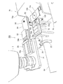


Classifications
-
- B—PERFORMING OPERATIONS; TRANSPORTING
- B25—HAND TOOLS; PORTABLE POWER-DRIVEN TOOLS; MANIPULATORS
- B25J—MANIPULATORS; CHAMBERS PROVIDED WITH MANIPULATION DEVICES
- B25J9/00—Program-controlled manipulators
- B25J9/0084—Program-controlled manipulators comprising a plurality of manipulators
- B25J9/0087—Dual arms
-
- B—PERFORMING OPERATIONS; TRANSPORTING
- B25—HAND TOOLS; PORTABLE POWER-DRIVEN TOOLS; MANIPULATORS
- B25J—MANIPULATORS; CHAMBERS PROVIDED WITH MANIPULATION DEVICES
- B25J9/00—Program-controlled manipulators
- B25J9/02—Program-controlled manipulators characterised by movement of the arms, e.g. cartesian coordinate type
- B25J9/04—Program-controlled manipulators characterised by movement of the arms, e.g. cartesian coordinate type by rotating at least one arm, excluding the head movement itself, e.g. cylindrical coordinate type or polar coordinate type
- B25J9/041—Cylindrical coordinate type
- B25J9/042—Cylindrical coordinate type comprising an articulated arm
- B25J9/043—Cylindrical coordinate type comprising an articulated arm double selective compliance articulated robot arms [SCARA]
-
- B—PERFORMING OPERATIONS; TRANSPORTING
- B23—MACHINE TOOLS; METAL-WORKING NOT OTHERWISE PROVIDED FOR
- B23P—METAL-WORKING NOT OTHERWISE PROVIDED FOR; COMBINED OPERATIONS; UNIVERSAL MACHINE TOOLS
- B23P19/00—Machines for simply fitting together or separating metal parts or objects, or metal and non-metal parts, whether or not involving some deformation; Tools or devices therefor so far as not provided for in other classes
- B23P19/04—Machines for simply fitting together or separating metal parts or objects, or metal and non-metal parts, whether or not involving some deformation; Tools or devices therefor so far as not provided for in other classes for assembling or disassembling parts
- B23P19/06—Screw or nut setting or loosening machines
-
- B—PERFORMING OPERATIONS; TRANSPORTING
- B23—MACHINE TOOLS; METAL-WORKING NOT OTHERWISE PROVIDED FOR
- B23P—METAL-WORKING NOT OTHERWISE PROVIDED FOR; COMBINED OPERATIONS; UNIVERSAL MACHINE TOOLS
- B23P21/00—Machines for assembling a multiplicity of different parts to compose units, with or without preceding or subsequent working of such parts, e.g. with program control
-
- B—PERFORMING OPERATIONS; TRANSPORTING
- B25—HAND TOOLS; PORTABLE POWER-DRIVEN TOOLS; MANIPULATORS
- B25J—MANIPULATORS; CHAMBERS PROVIDED WITH MANIPULATION DEVICES
- B25J11/00—Manipulators not otherwise provided for
-
- B—PERFORMING OPERATIONS; TRANSPORTING
- B25—HAND TOOLS; PORTABLE POWER-DRIVEN TOOLS; MANIPULATORS
- B25J—MANIPULATORS; CHAMBERS PROVIDED WITH MANIPULATION DEVICES
- B25J13/00—Controls for manipulators
- B25J13/06—Control stands, e.g. consoles, switchboards
-
- B—PERFORMING OPERATIONS; TRANSPORTING
- B25—HAND TOOLS; PORTABLE POWER-DRIVEN TOOLS; MANIPULATORS
- B25J—MANIPULATORS; CHAMBERS PROVIDED WITH MANIPULATION DEVICES
- B25J15/00—Gripping heads and other end effectors
- B25J15/0019—End effectors other than grippers
-
- B—PERFORMING OPERATIONS; TRANSPORTING
- B25—HAND TOOLS; PORTABLE POWER-DRIVEN TOOLS; MANIPULATORS
- B25J—MANIPULATORS; CHAMBERS PROVIDED WITH MANIPULATION DEVICES
- B25J15/00—Gripping heads and other end effectors
- B25J15/06—Gripping heads and other end effectors with vacuum or magnetic holding means
- B25J15/0616—Gripping heads and other end effectors with vacuum or magnetic holding means with vacuum
-
- B—PERFORMING OPERATIONS; TRANSPORTING
- B25—HAND TOOLS; PORTABLE POWER-DRIVEN TOOLS; MANIPULATORS
- B25J—MANIPULATORS; CHAMBERS PROVIDED WITH MANIPULATION DEVICES
- B25J15/00—Gripping heads and other end effectors
- B25J15/08—Gripping heads and other end effectors having finger members
-
- B—PERFORMING OPERATIONS; TRANSPORTING
- B25—HAND TOOLS; PORTABLE POWER-DRIVEN TOOLS; MANIPULATORS
- B25J—MANIPULATORS; CHAMBERS PROVIDED WITH MANIPULATION DEVICES
- B25J9/00—Program-controlled manipulators
- B25J9/0009—Constructional details, e.g. manipulator supports, bases
-
- B—PERFORMING OPERATIONS; TRANSPORTING
- B25—HAND TOOLS; PORTABLE POWER-DRIVEN TOOLS; MANIPULATORS
- B25J—MANIPULATORS; CHAMBERS PROVIDED WITH MANIPULATION DEVICES
- B25J9/00—Program-controlled manipulators
- B25J9/02—Program-controlled manipulators characterised by movement of the arms, e.g. cartesian coordinate type
- B25J9/04—Program-controlled manipulators characterised by movement of the arms, e.g. cartesian coordinate type by rotating at least one arm, excluding the head movement itself, e.g. cylindrical coordinate type or polar coordinate type
- B25J9/041—Cylindrical coordinate type
- B25J9/042—Cylindrical coordinate type comprising an articulated arm
- B25J9/044—Cylindrical coordinate type comprising an articulated arm with forearm providing vertical linear movement
-
- B—PERFORMING OPERATIONS; TRANSPORTING
- B25—HAND TOOLS; PORTABLE POWER-DRIVEN TOOLS; MANIPULATORS
- B25J—MANIPULATORS; CHAMBERS PROVIDED WITH MANIPULATION DEVICES
- B25J9/00—Program-controlled manipulators
- B25J9/16—Program controls
- B25J9/1679—Program controls characterised by the tasks executed
- B25J9/1687—Assembly, peg and hole, palletising, straight line, weaving pattern movement
-
- G—PHYSICS
- G05—CONTROLLING; REGULATING
- G05B—CONTROL OR REGULATING SYSTEMS IN GENERAL; FUNCTIONAL ELEMENTS OF SUCH SYSTEMS; MONITORING OR TESTING ARRANGEMENTS FOR SUCH SYSTEMS OR ELEMENTS
- G05B2219/00—Program-control systems
- G05B2219/30—Nc systems
- G05B2219/39—Robotics, robotics to robotics hand
- G05B2219/39001—Robot, manipulator control
-
- G—PHYSICS
- G05—CONTROLLING; REGULATING
- G05B—CONTROL OR REGULATING SYSTEMS IN GENERAL; FUNCTIONAL ELEMENTS OF SUCH SYSTEMS; MONITORING OR TESTING ARRANGEMENTS FOR SUCH SYSTEMS OR ELEMENTS
- G05B2219/00—Program-control systems
- G05B2219/30—Nc systems
- G05B2219/39—Robotics, robotics to robotics hand
- G05B2219/39129—One manipulator holds one piece, other inserts, screws other piece, dexterity
-
- G—PHYSICS
- G05—CONTROLLING; REGULATING
- G05B—CONTROL OR REGULATING SYSTEMS IN GENERAL; FUNCTIONAL ELEMENTS OF SUCH SYSTEMS; MONITORING OR TESTING ARRANGEMENTS FOR SUCH SYSTEMS OR ELEMENTS
- G05B2219/00—Program-control systems
- G05B2219/30—Nc systems
- G05B2219/40—Robotics, robotics mapping to robotics vision
- G05B2219/40066—Stack and align identical layers, laminates, electronic substrate layers
Definitions
- the present disclosure relates to a substrate assembly apparatus and a substrate assembly method using the substrate assembly apparatus.
- the electronic board assembly work includes, for example, a step of attaching spacer screws on the main board, a step of mounting electronic components on the assembly board, and screw tightening with the assembly board positioned at a predetermined position on the main board. The process is included.
- the above-mentioned conventional automatic screw tightening device is intended for the work of tightening screws at a predetermined position on a substrate. Therefore, there is room for further improvement in applying the above-mentioned conventional technique to the above-mentioned substrate assembly work.
- This disclosure is made to solve the above-mentioned problems, and aims to improve the productivity of the substrate assembly work involving screw tightening at the manufacturing site of electronic equipment.
- the substrate assembling device is an apparatus for assembling a substrate by laminating a first substrate and a second substrate, and is a base and a first attached to the base.
- a second end effector detachably attached to the tip of the head and a control device for controlling the operation of the first arm and the second arm are provided, and the second end effector is provided on the base and the base.
- the control device has a pair of gripping portions capable of gripping the second substrate and a mounting portion arranged on the base portion for mounting screws, and the control device is a pair of the second end effectors.
- the grip portion grips the second substrate while positioning the second substrate on the first substrate, and the first end effector causes a screw placed on the previously described portion of the second end effector.
- the operation of the first arm and the second arm is controlled so that the first substrate and the second substrate are bonded together to assemble the substrate by tightening the screws with the held screws while holding the substrate.
- a dual-arm robot positions the second substrate on the first substrate while gripping the second substrate by a pair of gripping portions of the second end effector at the tip of the second arm. After that, the first end effector at the tip of the first arm holds the screw mounted on the mounting portion of the second end effector, and the screw is tightened with the held screw. As a result, the first substrate and the second substrate can be bonded together to assemble the substrate. As a result, the productivity of the substrate assembly work involving screw tightening can be improved.
- the second end effector further includes a screw holding portion configured to hold a screw or a connecting portion configured to attach and detach the above-mentioned mounting portion
- the control device is the control device of the second end effector.
- the screw holding portion is connected to the connecting portion, the held screw is placed on the previously described mounting portion arranged at a predetermined position by the screw holding portion, and the previously described screw is placed on the connecting portion of the second end effector.
- the second substrate is positioned on the first substrate while gripping the second substrate by the pair of gripping portions of the second end effector, and the second end effector is used to position the second substrate on the first substrate.
- the first arm so as to assemble the board by laminating the first board and the second board by screwing with the held screw while holding the screw placed on the previously described mounting portion of the end effector. And the second operation may be controlled.
- the dual-arm robot itself can mount the screw on the mounting portion by the screw holding portion connected to the second end effector, and then connect the mounting portion to the second end effector.
- the board assembly device does not need to be equipped with a device for supplying screws.
- the board assembly work can be realized only by the robot system.
- the above-mentioned mounting portion may have a mounting space on which a plurality of screws can be mounted. According to the above configuration, the work of replenishing the screws during the substrate assembly work becomes unnecessary, so that the productivity is further improved.
- the substrate assembly device is configured to be detachably attached to the tip of the first arm, holds spacer screws for connecting the first substrate and the second substrate to each other, and is configured to be screw-tighten.
- the control device further includes a three-end effector, and the control device attaches the third end effector to the tip of the first arm, and the third end effector holds the spacer screw while holding the spacer screw.
- the operation of the first arm may be controlled so as to be screwed onto the substrate.
- the substrate assembly device further includes a fourth end effector configured to be detachably attached to the tip of the second arm and configured to hold electronic components, and the control device is attached to the tip of the second arm.
- the operation of the second arm may be controlled so that the fourth end effector is attached and the electronic component held by the fourth end effector is mounted on the second substrate.
- an electronic component for example, a memory
- the main body portion of the electronic component is arranged on the substrate, and the terminal portion of the electronic component penetrates a through hole provided in the substrate and is a substrate on the back side of the substrate. It is fixed (for example, soldered) to.
- the first substrate and the second substrate can be bonded together at a predetermined interval, so that the upper surface of the first substrate is the first. 2
- the first end effector may be configured to hold the screw by sucking the screw with a negative pressure and to be able to tighten the screw.
- the substrate assembly method is detachably attached to a base, a first arm attached to the base, a second arm attached to the base, and a tip of the first arm. Controls the operation of the first end effector, which holds the screw and is configured to be screw-tighten, the second end effector which is detachably attached to the tip of the second arm, and the first arm and the second arm.
- This is a method of assembling a substrate by laminating a first substrate and a second substrate by a substrate assembling apparatus provided with a control device, wherein the second end effector is provided on a base portion and the base portion.
- the control device has a pair of gripping portions capable of gripping both ends of the second substrate and a temporary mounting portion arranged on the base portion for mounting a screw, and the control device is a pair of the second end effectors.
- the second substrate was positioned on the first substrate while gripping both ends of the second substrate by the gripping portion, and was placed on the temporary placement portion of the second end effector by the first end effector.
- the operation of the first arm and the second arm is controlled so that the first substrate and the second substrate are bonded together to assemble the substrate by tightening the screws with the retained screws while holding the screws. ..
- the present disclosure has the configuration described above, and can improve the productivity of the substrate assembly work involving screw tightening at the manufacturing site of electronic equipment.
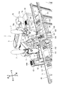
- FIG. 1 is a diagram showing a substrate assembly apparatus according to an embodiment of the present disclosure.
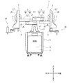
- FIG. 2 is a front view schematically showing the overall configuration of the robot.
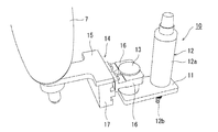
- FIG. 3 is a perspective view showing the configuration of the first end effector.
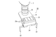
- FIG. 4 is a perspective view showing the configuration of the second end effector.
- FIG. 5 is a perspective view showing the configuration of the third end effector.
- FIG. 6 is a perspective view showing the configuration of the fourth end effector.
- FIG. 7 is a functional block diagram schematically showing the configuration of the control device.
- FIG. 8 is a flowchart showing the operation procedure of the board assembly apparatus.
- FIG. 9 is a diagram for explaining a process of substrate assembly work.
- FIG. 10 is a diagram for explaining the operation of the substrate assembly apparatus.
- FIG. 9 is a diagram for explaining a process of substrate assembly work.
- FIG. 11 is a second diagram for explaining the operation of the substrate assembly apparatus.
- FIG. 12 is a perspective view showing a modified example of the first end effector.
- FIG. 13 is a perspective view showing a first aspect of the end effector of FIG.
- FIG. 14 is a perspective view showing a second aspect of the end effector of FIG.
- FIG. 15 is a perspective view for explaining the operation of the substrate assembly apparatus of this modified example.
- FIG. 1 is a diagram showing a substrate assembly apparatus according to an embodiment of the present disclosure.
- the substrate assembling device of the present embodiment is introduced into a manufacturing site of an electronic device such as a computer, and performs an operation of bonding two substrates (hereinafter, referred to as "board assembling operation").
- the substrate assembly device is composed of a base 2 and a robot 1 provided with a pair of robot arms (hereinafter, may be simply referred to as “arms”) 3 and 3 attached to the base 2. Will be done.
- the direction in which the pair of arms is spread is referred to as a left-right direction.
- the direction parallel to the axis of the base 2 is referred to as the vertical direction.
- the direction orthogonal to the left-right direction and the up-down direction is called the front-back direction.
- the robot 1 operates the left and right arms 3 and 3 to perform the board assembly work by the end effectors 10 and 20 attached to the tips (wrist portions 7 and 7) of the arms 3 and 3. ..
- the first table 61 is installed in front of the base 2 of the robot 1.
- a workbench 72 is arranged on the first table 61.
- the robot 1 performs the work of mounting the electronic component 104 on the second substrate 102 on the workbench 72.
- a conveyor 65 is arranged in front of the first table 61.
- the conveyor 65 has a pair of rail members extending in the left-right direction.
- a plurality of work plates 71 are placed on a pair of rail members so as to be movable in the left-right direction.
- a first substrate 101 and a second substrate 102 are arranged on each work plate 71.
- the robot 1 assembles these boards on the work plate 71 located in front of the robot 1.
- the work plate 71 for which the substrate assembly work has been completed is sequentially conveyed on the conveyor 65.
- the second table 62 is arranged on the left side of the first table 61.
- a replaceable end effector is arranged on the tip of the right arm 3 of the robot 1 on the second table 62.
- the third table 63 is arranged diagonally to the right and rearward of the second table 62.
- a component case 73 in which the electronic component 104 is housed is arranged on the third table 63.
- the electronic component 104 is an integrated circuit such as a memory mounted on a substrate.
- a fourth table 64 is installed on the left side of the base 2 of the robot 1.
- a screw case 74 and a screw supply device 75 are arranged on the fourth table 64. Spacer screws are placed on the screw case 74.
- the screw feeding device 75 includes a screw feeding unit 75a and a screw feeding unit 75b.
- the screw feeding unit 75a is a device for accommodating a plurality of screws and sequentially feeding the accommodated screws one by one.
- the screw supply unit 75b is a device for holding the screws sequentially fed by the screw feeding unit 75a and supplying them to the robot 1.
- FIG. 2 is a front view schematically showing the overall configuration of the robot 1.
- the robot 1 includes a base 2 fixed to a carriage 6, a pair of arms 3 and 3 supported by the base 2, a control device 4 and a vacuum generator 8 housed in the base 2. It has.
- the vacuum generator 8 is a device that generates a negative pressure in a suction type driver 12b (see FIG. 3) described later, such as a vacuum pump or CONVUM (registered trademark).
- the front, rear, left and right dimensions of the dolly 6 are, for example, 610 mm ⁇ 620 mm. Therefore, the robot 1 can be installed in a limited space corresponding to one person.
- Each arm 3 is a horizontal articulated robot arm configured to be movable with respect to the base 2.
- the arm 3 includes an arm portion 5 and a wrist portion 7. Further, the left and right arms 3 and 3 can operate independently or in relation to each other.
- the arm portion 5 is composed of a first link 5a and a second link 5b.
- the first link 5a is connected to a base shaft (not shown) fixed to the upper surface of the base 2 by a rotary joint J1 and is rotatable around a rotation axis L1 passing through the axis of the base shaft.
- the second link 5b is connected to the tip of the first link 5a by a rotary joint J2 and can rotate around the rotation axis L2 defined at the tip of the first link 5a.
- the wrist unit 7 is composed of an elevating unit 7a and a rotating unit 7b.
- the elevating portion 7a is connected to the tip of the second link 5b by a linear motion joint J3, and can move up and down with respect to the second link 5b.
- the rotating portion 7b is connected to the lower end of the elevating portion 7a by a rotary joint J4, and can rotate around the rotation axis L3 defined at the lower end of the elevating portion 7a.
- An end effector 10 is connected to the wrist portion 7 of the right arm 3 via a mechanical interface 9.
- An end effector 20 is connected to the wrist portion 7 of the left arm 3 via a mechanical interface 9.
- Each arm 3 having the above configuration has joints J1 to J4.
- the arm 3 is provided with a servomotor for driving (not shown), an encoder (not shown) for detecting the rotation angle of the servomotor, and the like so as to be associated with the joints J1 to J4.
- a servomotor for driving (not shown)
- an encoder for detecting the rotation angle of the servomotor, and the like so as to be associated with the joints J1 to J4.
- the rotation axes L1 of the first links 5a and 5a of the two arms 3 and 3 are on the same straight line, and the first link 5a of one arm 3 and the first link 5a of the other arm 3 are up and down. They are arranged with a height difference.
- FIG. 3 is a perspective view showing the configuration of the end effector 10.
- the end effector 10 corresponds to the "first end effector" of the present disclosure.
- the end effector 10 includes a base hand 14, an adapter 13 held by the base hand 14, a base 11 connected to the adapter 13, and a screw tightening portion 12 attached to the base 11. To be equipped.
- the base hand 14 includes a platform 15 and a pair of fingers 16 supported by the platform 15.
- the platform 15 has a T-shaped flat plate shape.
- the base end side of the platform 15 is coupled to the mechanical interface 9 (see FIG. 2) provided in the wrist portion 7 of the right arm 3.
- the pair of parallel fingers 16 are driven by a drive unit 17 (actuator) provided on the tip side of the platform 15 and move in translation so as to approach and separate from each other while maintaining parallelism.
- the actuator may be composed of, for example, an air cylinder or a linear motion mechanism.
- the upper part of the adapter 13 has a cylindrical shape or a cylindrical shape.
- An engaging portion for engaging the fingers 16 of the base hand 14 is provided on the outer peripheral surface of the adapter 13.
- the base 11 has a flat plate shape.
- the base end of the upper surface of the base 11 is coupled to the lower portion of the adapter 13, and the tip of the upper surface of the base 11 is coupled to the screw tightening portion 12.
- the screw tightening portion 12 includes a cylindrical main body portion 12a attached to the base portion 11 and a driver 12b attached to the tip of the main body portion 12a.
- the main body 12a is configured to supply the negative pressure generated by the vacuum generator 8 (see FIG. 2) to the tip of the driver 12b.
- the driver 12b is a so-called suction type driver.
- the driver 12b is configured to hold the screw by sucking the screw with a negative pressure and to be able to tighten the screw.
- FIG. 4 is a perspective view showing the configuration of the end effector 20.
- the end effector 20 corresponds to the "second end effector" of the present disclosure.
- the end effector 20 has a platform 25, a base 21, a pair of grips 22 and 22 provided on the base 21, and a mounting portion 23.
- the platform 25 has a cylindrical shape.
- the upper portion of the platform 25 is coupled to the mechanical interface 9 (see FIG. 2) provided on the wrist portion 7 of the left arm 3, and the lower portion of the platform 25 is coupled to the base portion 21.
- the base 21 has a flat plate shape.
- the base end of the top surface of the base 21 is detachably coupled to the bottom of the platform 25.
- the mounting portion 23 is arranged at the tip of the upper surface of the base portion 21.
- the mounting portion 23 has a flat plate shape.
- the mounting portion 23 has a mounting space on which a plurality of screws can be mounted.
- 16 (4 ⁇ 4) recesses 23a are provided on the upper surface of the mounting portion 23.
- Each recess 23a has a volume corresponding to the shape of the tip of the screw. 16 screws can be mounted in the recess 23a of the mounting portion 23.
- the pair of grips 22, 22 are driven by a drive unit (actuator) 24 provided at the tip of the lower surface of the base 21, and move in translation so as to approach and separate from each other while maintaining parallelism.
- the pair of gripping portions 22, 22 are configured to be able to grip the second substrate 102.
- FIG. 5 is a perspective view showing the configuration of the end effector 30.
- the end effector 30 corresponds to the "third end effector" of the present disclosure.
- the end effector 30 includes a platform 25 connected to a wrist portion 7 of the left arm 3, a base portion 31 detachably attached to the platform 25, and a screw tightening portion provided on the base portion 31. 32 and.
- the base 31 has a cylindrical shape. The upper surface of the base 31 is connected to the platform 25, and the lower surface of the base 31 is connected to the screw tightening portion 32.
- the screw tightening portion 32 holds spacer screws for connecting the first board 101 and the second board 102 to each other, and is configured to be screw-tighten.
- the configuration of the screw tightening portion 32 is not particularly limited.
- FIG. 6 is a perspective view showing the configuration of the end effector 40.
- the end effector 40 includes a base hand 14, an adapter 13 held by the base hand 14, a base 41 connected to the adapter 13, and a pair of grip portions provided below the base 41. 42, 42 and.
- the base 41 has a flat plate shape. One end of the upper surface of the base 41 is coupled to the lower part of the adapter 13. Further, a pressing portion 44 is attached to one end of the upper surface of the base portion 41. The pressing portion 44 has a flat plate shape. When the pressing portion 44 is pressed against the work plate 71 on the conveyor 65, the work plate 71 is conveyed on the conveyor 65.
- the pair of grip portions 42, 42 are connected via a drive portion 43 (actuator) provided at the lower end of the other end of the base portion 41.
- the pair of grips 42, 42 are driven by the drive unit 43 and move in translation so as to approach and separate from each other while maintaining parallelism.
- the pair of gripping portions 42, 42 are configured to be able to grip the electronic component 104.
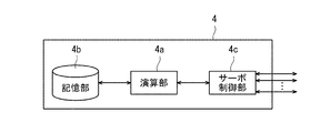
- FIG. 7 is a functional block diagram schematically showing the configuration of the control device 4 of the robot 1 of FIG.
- the control device 4 includes a calculation unit 4a such as a CPU, a storage unit 4b such as a ROM and a RAM, and a servo control unit 4c.
- the control device 4 is a robot controller including a computer such as a microcontroller.
- the control device 4 may be composed of a single control device 4 for centralized control, or may be composed of a plurality of control devices 4 for distributed control in cooperation with each other.
- the calculation unit 4a controls various operations of the robot 1 by reading and executing software such as a basic program stored in the storage unit 4b. That is, the calculation unit 4a generates a control command for the robot 1 and outputs the control command to the servo control unit 4c.
- the servo control unit 4c is configured to control the drive of the servo motor corresponding to the joints J1 to J4 of each arm 3 of the robot 1 based on the control command generated by the calculation unit 4a.
- the control device 4 also controls the operation of the end effectors 10, 20, 30, and 40. Therefore, the control device 4 controls the operation of the entire robot 1.
- FIG. 8 is a flowchart showing the operation procedure of the robot 1.
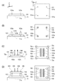
- FIG. 9 is a front view and a plan view for explaining the process of substrate assembly work.
- 10 and 11 are diagrams for explaining the operation of the robot 1.
- the first substrate 101 Prior to the start of the substrate assembly work, the first substrate 101 is placed in a predetermined position on the work plate 71 (see FIG. 9A). A recess 71a having a shape corresponding to the first substrate 101 is provided on the upper surface of the work plate 71, and the first substrate 101 is fitted in the recess 71a. As a result, the first substrate 101 is fixed at a predetermined position on the work plate 71.
- Four screw holes 101a are provided in the vicinity of the four corners on the first substrate 101 having a rectangular shape in a plan view.
- the robot 1 attaches the spacer screw 103 on the first substrate 101 (see step S1 in FIG. 8).
- the control device 4 controls the operation of the left arm 3 and attaches the end effector 30 to the tip of the left arm 3.
- the control device 4 controls the operation of the left arm 3, and the end effector 30 holds the spacer screw 103 mounted on the screw case 74 on the fourth table 64 while holding the spacer screw 103.
- a female screw 103a is provided at the upper end of the spacer screw 103
- a male screw 103b is provided at the lower end of the spacer screw 103.
- Spacer screws 103 are screwed into the four screw holes 101a on the first substrate 101.
- the robot 1 mounts the electronic component 104 on the second substrate 102 (see step S2 in FIG. 8).
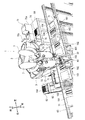
- the control device 4 controls the operation of the left arm 3 and attaches the end effector 20 to the tip of the left arm 3.
- the control device 4 controls the operation of the left arm 3, holds the second board 102 by the end effector 20, and holds the second board 102 held by the end effector 20 as the workbench of the first table 61. Place it on 72.
- the four corners of the second substrate 102 are fixed by four fixing jigs 72a provided on the workbench 72.
- the control device 4 controls the operation of the right arm 3 and attaches the end effector 40 to the tip of the right arm 3. Then, the control device 4 controls the operation of the right arm 3 and holds the electronic component 104 housed in the component case 73 of the third table 63 by the end effector 40, and the electronic component held by the end effector 40.
- the component 104 is mounted on the second substrate 102 mounted on the workbench 72 of the first table 61 (see FIG. 11).
- the electronic component 104 is mounted on the second substrate 102 via the connection terminal 102a.
- four through holes 102b are provided in the vicinity of the four corners on the second substrate 102 having a rectangular shape in a plan view.
- the robot 1 attaches the first substrate 101 and the second substrate 102 by screw tightening (see step S3 in FIG. 8).
- the control device 4 controls the operation of the left arm 3 to supply the screw 105 to the end effector 20.
- the control device 4 moves the end effector 20 to a predetermined position in the vicinity of the screw supply device 75 of the fourth table 64 (see FIG. 11), and the screw supply device 75 (screw supply unit 75b) causes the end effector 20 (screw).
- the screw 105 is supplied to the mounting portion 23) of the above.
- the control device 4 controls the operation of the right arm 3 and attaches the end effector 10 to the tip of the right arm 3.
- the control device 4 controls the operation of the left arm 3, grips the second substrate 102 of the workbench 72 by the end effector 20 (a pair of grip portions 22), and holds the second substrate 102 on the work plate 71.
- the second substrate 102 is positioned on the first substrate 101 of the work plate 71 (see FIG. 1).
- the control device 4 controls the operation of the right arm 3, and the end effector 10 holds the screw 105 mounted on the end effector 20 (mounting portion 23), and the screw 105 holds the screw. Tighten.
- the screw 105 is fitted with the upper ends of the four spacer screws 103 on the first substrate 101 through the four through holes 102b provided in the second substrate 102. It is screwed to the screw 103a. As a result, the first substrate 101 and the second substrate 102 are bonded together, and the substrate assembly work is completed.
- the dual-arm robot 1 positions the second substrate 102 on the first substrate 101 while gripping the second substrate 102 by the end effectors 20 (a pair of gripping portions 22, 22). .. After that, the end effector 10 holds the screw 105 mounted on the mounting portion 23 of the end effector 20, and tightens the screw with the held screw 105. As a result, the first substrate 101 and the second substrate 102 can be bonded together to assemble the substrate. As a result, the productivity of the substrate assembly work involving screw tightening can be improved.
- the first substrate 101 and the second substrate 102 can be bonded together at a predetermined interval, so that the electronic component 104 is attached to the back side of the second substrate 102. Even if the terminals of the above are present, they do not come into contact with the upper surface of the first substrate 101.
- the mounting portion 23 since the mounting portion 23 has a mounting space (recessed portion 23a) on which a plurality of screws 105 can be mounted, it is not necessary to replenish the screws 105 during the board assembly work. Become. Productivity is further improved.
- the end effector 10 is provided with the suction type driver 12b, efficient screw tightening work can be performed, and the productivity of the board assembly work is further improved.
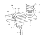
- FIG. 12 is a perspective view showing a modified example of the end effector 20.
- the end effector 20A of this modification is provided with a connecting portion 26 at the tip of the upper surface of the base portion 21 instead of the mounting portion 23.
- the connecting portion 26 of this modified example includes a driving portion 26a provided at the tip of the upper surface of the base portion 21, and a pair of grip portions 26b and 26b.
- the pair of gripping portions 26b and 26b are driven by the driving portion 26a and move in translation so as to approach and separate from each other while maintaining parallelism.
- the pair of gripping portions 26b, 26b are configured to be able to grip an object.
- the control device 4 controls the operation of the left arm 3 and attaches the end effector 20A to the tip (wrist portion 7) of the left arm 3.
- FIG. 13 is a perspective view showing a first aspect of the end effector 20A.
- the end effector 20A is connected to the transfer tool 50 by the connecting portion 26.
- the transfer tool 50 includes an adapter 53, a base 51 connected to the adapter 53, and a screw holding portion 52 provided below the base 51.
- the screw holding portion 52 is configured to be able to hold or release the screw 105.
- the control device 4 controls the operation of the left arm 3 and grips the adapter 13 of the transfer tool 50 by the pair of gripping portions 26b and 26b of the connecting portion 26. As a result, the transfer tool 50 is connected to the end effector 20A.
- the control device 4 controls the operation of the left arm 3 to move the end effector 20A to the vicinity of the screw supply device 75 of the fourth table 64, and the screw holding portion 52 from the stage 75c of the screw supply unit 75b.
- the screw 105 to be sent out is held and placed in the recess 23a of the mounting portion 23A arranged on the stand 76 adjacent to the screw supply unit 75b.
- FIG. 14 is a perspective view showing a second aspect of the end effector 20A.
- the end effector 20A is connected to the mounting portion 23A by the connecting portion 26.
- the control device 4 controls the operation of the left arm 3 and grips the mounting portion 23A by the pair of grip portions 26b and 26b of the connecting portion 26.
- the mounting portion 23A is connected to the end effector 20A.
- the connecting portion 26 of the end effector 20A is configured so that the screw holding portion 52 or the mounting portion 23A can be attached and detached.
- FIG. 15 is a perspective view for explaining the operation of the robot 1A (board assembly device) of this modified example.
- the control device 4 controls the operation of the left arm 3, and as shown in FIG. 15, the control device 4 grips the second substrate 102 by the end effectors 20A (a pair of gripping portions 22, 22) while gripping the second substrate 102. Is positioned on the first substrate 101.
- the control device 4 controls the operation of the right arm 3, and the end effector 10 holds the screw 105 mounted on the end effector 20A (mounting portion 23A), and the screw 105 holds the screw 105.
- the first substrate 101 and the second substrate 102 are bonded together to assemble the substrate.
- the robot 1 itself mounts the screw 105 on the mounting portion 23A by the screw holding portion 52 connected to the end effector 20A, and then connects the mounting portion 23A to the end effector 20A. Therefore, the screw supply unit 75b (see FIG. 1) of the screw supply device 75 is not required.
- the board assembly work can be realized only by the robot system.
- the substrate assembly device of the above embodiment is composed of a horizontal articulated dual-arm robot, a vertical articulated dual-arm robot may be adopted.
- This disclosure is useful for substrate assembly work at the manufacturing site of electronic devices such as computers.
Landscapes
- Engineering & Computer Science (AREA)
- Mechanical Engineering (AREA)
- Robotics (AREA)
- Manipulator (AREA)
- Automatic Assembly (AREA)
Abstract
基板組立装置(1)は、第1アーム(3)に取り付けられた第1エンドエフェクタ10と、第2アーム(3)に取り付けられた第2エンドエフェクタ20と、制御装置4と、を備える。第2エンドエフェクタ20は、第2基板102を把持可能な一対の把持部22,22と、ねじを載置するための載置部23と、を有する。制御装置4が、第2エンドエフェクタ20の一対の把持部22,22により、第2基板102を把持しつつ第2基板102を第1基板101上に位置決めし、第1エンドエフェクタ10により、第2エンドエフェクタ20の載置部23に載置されたねじを保持しつつ、保持したねじでねじ締めすることにより第1基板101と第2基板102とを貼り合わせるように第1アーム及び第2アームの動作を制御する。
Description
本開示は、基板組立装置及びそれを用いた基板組立方法に関する。
従来、コンピュータ等の電子機器の製造現場では、電子基板の組立作業は作業者により行われていた。電子基板の組立作業には、例えば、メイン基板上にスペーサねじを取り付ける工程、組立基板上に電子部品を実装する工程、及び、組立基板をメイン基板上の所定位置に位置決めした状態でねじ締めする工程が含まれる。
近年、様々な分野において、生産性向上の観点から、ロボットと作業者が同じ作業空間内で共同して作業を行うことが提案されている。上記製造現場において人型の作業ロボットを導入し、基板の組立作業を行う場合、ロボットは、作業者と同様に、複雑な作業工程を正確に実施しなければならない。
従来から、電気機器や機械装置等の組立に使用される自動ねじ締め装置が知られている(例えば特許文献1及び特許文献2参照)。
上記従来の自動ねじ締め装置は、基板の所定位置にねじ締めを行う作業を対象としている。このため、上記のような基板組立作業に上記従来技術を適用するには更なる改善の余地があった。
本開示は上記のような課題を解決するためになされたもので、電子機器の製造現場において、ねじ締めを伴う基板組立作業の生産性を向上することを目的としている。
上記目的を達成するために、本開示のある形態に係る基板組立装置は、第1基板と第2基板とを貼り合わせて基板を組み立てる装置であって、ベースと、前記ベースに取り付けられた第1アームと、前記ベースに取り付けられた第2アームと、前記第1アームの先端に着脱可能に取り付けられ、ねじを保持し且つねじ締め可能に構成された第1エンドエフェクタと、前記第2アームの先端に着脱可能に取り付けられた第2エンドエフェクタと、前記第1アーム及び第2アームの動作を制御する制御装置と、を備え、前記第2エンドエフェクタが、基部と、前記基部に設けられ、前記第2基板を把持可能な一対の把持部と、前記基部に配置され、ねじを載置するための載置部と、を有し、前記制御装置が、前記第2エンドエフェクタの一対の把持部により、前記第2基板を把持しつつ当該第2基板を前記第1基板上に位置決めし、前記第1エンドエフェクタにより、前記第2エンドエフェクタの前記載置部に載置されたねじを保持しつつ、保持したねじでねじ締めすることにより前記第1基板と前記第2基板とを貼り合わせて基板を組み立てるように前記第1アーム及び第2アームの動作を制御するものである。
上記構成によれば、例えば双腕ロボットにより、第2アーム先端の第2エンドエフェク タの一対の把持部により、第2基板を把持しつつ当該第2基板を第1基板上に位置決めする。その後、第1アーム先端の第1エンドエフェクタにより、第2エンドエフェクタの載置部に載置されたねじを保持しつつ、保持したねじでねじ締めする。これにより、第1基板と第2基板とを貼り合わせて基板を組み立てることができる。これにより、ねじ締めを伴う基板組立作業の生産性を向上することができる。
また、前記第2エンドエフェクタが、ねじを保持可能に構成されたねじ保持部又は前記載置部を着脱可能に構成された連結部を更に備え、前記制御装置が、前記第2エンドエフェクタの前記連結部に前記ねじ保持部を連結し、前記ねじ保持部により、保持したねじを所定の位置に配置された前記載置部に載置し、前記第2エンドエフェクタの前記連結部に前記載置部を連結し、前記第2エンドエフェクタの前記一対の把持部により、前記第2基板を把持しつつ当該第2基板を前記第1基板上に位置決めし、前記第1エンドエフェクタにより、前記第2エンドエフェクタの前記載置部に載置されたねじを保持しつつ、保持したねじでねじ締めすることにより前記第1基板と前記第2基板とを貼り合わせて基板を組み立てるように前記第1アーム及び第2の動作を制御してもよい。
上記構成によれば、例えば双腕ロボット自身が、第2エンドエフェクタに連結したねじ保持部により、ねじを載置部に載置し、その後、第2エンドエフェクタに載置部を連結することができるので、基板組立装置がねじを供給するための装置を備えている必要が無い。ロボットシステムのみで基板組立作業を実現することができる。
前記載置部は、複数のねじを載置可能な載置スペースを有してもよい。上記構成によれば、基板組立作業中にねじを補給する作業が不要になるので、生産性が更に向上する。
上記基板組立装置は、前記第1アームの先端に着脱可能に構成され、前記第1基板と前記第2基板とを互いに接続するためのスペーサねじを保持し、且つねじ締め可能に構成された第3エンドエフェクタを更に備え、前記制御装置は、前記第1アームの先端に前記第3エンドエフェクタを取り付け、前記第3エンドエフェクタにより、前記スペーサねじを保持しつつ、保持したスペーサねじを前記第1基板上にねじ締めするように前記第1アームの動作を制御してもよい。
さらに、上記基板組立装置は、前記第2アームの先端に着脱可能に構成され、電子部品を保持可能に構成された第4エンドエフェクタを更に備え、前記制御装置は、前記第2アームの先端に前記第4エンドエフェクタを取り付け、前記第4エンドエフェクタにより、保持した前記電子部品を、前記第2基板上に実装するように前記第2アームの動作を制御してもよい。
一般に電子部品(例えばメモリ)を基板上に実装する際には、電子部品の本体部分は基板上に配置され、電子部品の端子部分は基板に設けられた貫通孔を貫通し基板の裏側で基板に固定(例えば半田付け)される。上記構成によれば、スペーサねじを第1基板上にねじ締めすることにより、第1基板と第2基板とを所定の間隔を空けて貼り合わせることができるので、第1基板の上面が、第2基板の裏側に位置する電子部品の端子と接触することがない。上記構成によれば、電子機器の製造現場において、電子部品が実装された基板の組立作業の生産性を向上することができる。
尚、前記第1エンドエフェクタは、負圧によって前記ねじを吸引することにより当該ねじを保持し、且つねじ締め可能に構成されてもよい。
上記構成によれば、第1エンドエフェクタに吸引式のドライバー(screwdriver)を使用することで、効率の良いねじ締め作業を実施でき、基板組立作業の生産性が更に向上する。
本開示のその他の形態に係る基板組立方法は、ベースと、前記ベースに取り付けられた第1アームと、前記ベースに取り付けられた第2アームと、前記第1アームの先端に着脱可能に取り付けられ、ねじを保持し且つねじ締め可能に構成された第1エンドエフェクタと、前記第2アームの先端に着脱可能に取り付けられた第2エンドエフェクタと、前記第1アーム及び第2アームの動作を制御する制御装置と、を備えた基板組立装置により、第1基板と第2基板とを貼り合わせて基板を組み立てる方法であって、前記第2エンドエフェクタが、基部と、前記基部に設けられ、前記第2基板の両端を把持可能な一対の把持部と、前記基部に配置され、ねじを載置するための仮置き部と、を有し、前記制御装置が、前記第2エンドエフェクタの一対の把持部により、前記第2基板の両端を把持しつつ当該第2基板を前記第1基板上に位置決めし、前記第1エンドエフェクタにより、前記第2エンドエフェクタの前記仮置き部に載置されたねじを保持しつつ、保持したねじでねじ締めすることにより前記第1基板と前記第2基板とを貼り合わせて基板を組み立てるように前記第1アーム及び第2アームの動作を制御するものである。
本開示は、以上に説明した構成を有し、電子機器の製造現場において、ねじ締めを伴う基板組立作業の生産性を向上することができる。
以下、好ましい実施形態を、図面を参照しながら説明する。なお、以下では全ての図面を通じて同一または相当する要素には同一の参照符号を付して、その重複する説明を省略する。また、図面は理解しやすくするために、それぞれの構成要素を模式的に示したものである。
(実施形態)
図1は、本開示の一実施形態に係る基板組立装置を示す図である。本実施形態の基板組立装置は、例えばコンピュータ等の電子機器の製造現場に導入され、2枚の基板を貼り合わせる作業(以下、「基板組立作業」と呼ぶ)を実施する。図1に示すように、基板組立装置は、ベース2と、ベース2に取り付けられた一対のロボットアーム(以下、単に「アーム」と記載する場合がある)3,3を備えたロボット1により構成される。以下では、一対のアームを広げた方向を左右方向と称する。ベース2の基軸の軸心に平行な方向を上下方向と称する。左右方向および上下方向に直交する方向を前後方向と称する。本実施形態では、ロボット1は、左右のアーム3,3を動作させて、アーム3,3の先端(リスト部7,7)に取り付けられたエンドエフェクタ10,20により、基板組立作業を実施する。
図1は、本開示の一実施形態に係る基板組立装置を示す図である。本実施形態の基板組立装置は、例えばコンピュータ等の電子機器の製造現場に導入され、2枚の基板を貼り合わせる作業(以下、「基板組立作業」と呼ぶ)を実施する。図1に示すように、基板組立装置は、ベース2と、ベース2に取り付けられた一対のロボットアーム(以下、単に「アーム」と記載する場合がある)3,3を備えたロボット1により構成される。以下では、一対のアームを広げた方向を左右方向と称する。ベース2の基軸の軸心に平行な方向を上下方向と称する。左右方向および上下方向に直交する方向を前後方向と称する。本実施形態では、ロボット1は、左右のアーム3,3を動作させて、アーム3,3の先端(リスト部7,7)に取り付けられたエンドエフェクタ10,20により、基板組立作業を実施する。
ロボット1のベース2の前方には第1テーブル61が設置される。第1テーブル61の上には作業台72が配置される。ロボット1は、作業台72の上で第2基板102上に電子部品104を実装する作業を行う。第1テーブル61の前方にはコンベア65が配置される。コンベア65は左右方向に延びた一対のレール部材を有する。複数の作業プレート71が一対のレール部材の上を左右方向に移動可能に載置されている。各作業プレート71上には第1基板101及び第2基板102が配置される。ロボット1は、前方に位置する作業プレート71上でこれらの基板の組立作業を行う。基板組立作業が完了した作業プレート71はコンベア65上を順次搬送される。第1テーブル61の左側には第2テーブル62が配置される。第2テーブル62の上にはロボット1の右のアーム3の先端に取り換え可能なエンドエフェクタが配置される。第2テーブル62の右斜め後方には第3テーブル63が配置される。第3テーブル63の上には電子部品104が収納された部品ケース73が配置される。電子部品104は、基板上に実装されたメモリ等の集積回路である。ロボット1のベース2の左側には第4テーブル64が設置される。第4テーブル64の上には、ねじケース74及びねじ供給装置75が配置される。ねじケース74には、スペーサねじが載置されている。本実施形態では、ねじ供給装置75は、ねじ送り出しユニット75aとねじ供給ユニット75bを含む。ねじ送り出しユニット75aは、複数のねじを収容するとともに、収容されたねじを一つずつ順次送り出すための装置である。ねじ供給ユニット75bは、ねじ送り出しユニット75aにより順次送り出されたねじを保持し、ロボット1に供給するための装置である。
図2は、ロボット1の全体的な構成を概略的に示す正面図である。図2に示すように、ロボット1は、台車6に固定されたベース2と、ベース2に支持された一対のアーム3、3と、ベース2内に収納された制御装置4及び真空発生装置8を備えている。真空発生装置8は、たとえば、真空ポンプやCONVUM(登録商標)など、後述する吸引式のドライバ12b(図3参照)に負圧を発生させる装置である。台車6の前後左右の寸法は例えば610mm×620mmである。このため、ロボット1は、人一人分に相当する限られたスペースに設置することができる。各アーム3は、ベース2に対して移動可能に構成された水平多関節型ロボットアームである。アーム3は、アーム部5と、リスト部7と、を備えている。また、左右のアーム3,3は、独立して動作したり、互いに関連して動作したりすることができる。
アーム部5は、本例では、第1リンク5aおよび第2リンク5bとで構成されている。第1リンク5aは、ベース2の上面に固定された基軸(図示せず)と回転関節J1により連結され、基軸の軸心を通る回転軸線L1まわりに回動可能である。第2リンク5bは、第1リンク5aの先端と回転関節J2により連結され、第1リンク5aの先端に規定された回転軸線L2まわりに回動可能である。
リスト部7は、昇降部7aおよび回動部7bにより構成されている。昇降部7aは、第2リンク5bの先端と直動関節J3により連結され、第2リンク5bに対し昇降移動可能である。回動部7bは、昇降部7aの下端と回転関節J4により連結され、昇降部7aの下端に規定された回転軸線L3まわりに回動可能である。右のアーム3のリスト部7には、メカニカルインターフェース9を介してエンドエフェクタ10が連結されている。左のアーム3のリスト部7には、メカニカルインターフェース9を介してエンドエフェクタ20が連結されている。
上記構成の各アーム3は、各関節J1~J4を有する。そして、アーム3には、各関節J1~J4に対応付けられるように、駆動用のサーボモータ(図示せず)、および、そのサーボモータの回転角を検出するエンコーダ(図示せず)等が設けられている。また、2本のアーム3、3の第1リンク5a、5aの回転軸線L1は同一直線上にあり、一方のアーム3の第1リンク5aと他方のアーム3の第1リンク5aとは上下に高低差を設けて配置されている。
次に、右のアーム3に先端に取り付けられたエンドエフェクタ10の構成について説明する。図3は、エンドエフェクタ10の構成を示した斜視図である。エンドエフェクタ10は本開示の「第1エンドエフェクタ」に相当する。図3に示すように、エンドエフェクタ10は、ベースハンド14と、ベースハンド14により保持されたアダプタ13と、アダプタ13に連結された基部11と、基部11に取り付けられたねじ締め部12と、を備える。
ベースハンド14は、プラットホーム15と、プラットホーム15に支持された一対の指16とを備えている。プラットホーム15は、T字型の平板形状を有する。プラットホーム15の基端側が右のアーム3のリスト部7に設けられたメカニカルインターフェース9(図2参照)と結合される。平行な一対の指16は、プラットホーム15の先端側に設けられた駆動部17(アクチュエータ)によって駆動されて、平行を維持しながら互いに近接・離反するように並進移動する。アクチュエータは、例えば、エアシリンダや直動機構などにより構成されていてよい。
アダプタ13の上部は、円柱形状又は円筒形状である。アダプタ13の外周面には、ベースハンド14の指16を係合させる係合部が設けられている。
基部11は、平板形状である。基部11の上面の基端が、アダプタ13の下部と結合され、基部11の上面の先端が、ねじ締め部12と結合される。
ねじ締め部12は、基部11に取り付けられた円筒形の本体部12aと、本体部12aの先端に取り付けられたドライバ12bとを備える。本体部12aは、真空発生装置8(図2参照)により発生した負圧をドライバ12bの先端に供給するように構成される。ドライバ12bは、いわゆる、吸引式のドライバである。ドライバ12bは、負圧によってねじを吸引することにより当該ねじを保持し、且つねじ締め可能に構成される。
次に、左のアーム3に先端に取り付けられたエンドエフェクタ20の構成について説明する。図4は、エンドエフェクタ20の構成を示した斜視図である。エンドエフェクタ20は本開示の「第2エンドエフェクタ」に相当する。図4に示すように、エンドエフェクタ20は、プラットホーム25と、基部21と、基部21に設けられた一対の把持部22,22と、載置部23と、を有する。
プラットホーム25は、円柱形状を有する。プラットホーム25の上部は、左のアーム3のリスト部7に設けられたメカニカルインターフェース9(図2参照)と結合され、プラットホーム25の下部は、基部21と結合される。
基部21は、平板形状である。基部21の上面の基端が、プラットホーム25の下部と着脱可能に結合される。載置部23は、基部21の上面の先端に配置される。載置部23は、平板形状を有する。載置部23は、複数のねじを載置可能な載置スペースを有する。本実施形態では、載置部23の上面には16個(4×4)の凹部23aが設けられる。各凹部23aは、ねじの先端部の形状に応じた容積を有する。載置部23の凹部23aには16個のねじを載置することができる。
一対の把持部22,22は、基部21の下面の先端に先端側に設けられた駆動部(アクチュエータ)24によって駆動されて、平行を維持しながら互いに近接・離反するように並進移動する。一対の把持部22,22は、第2基板102を把持可能に構成される。
次に、左のアーム3に先端に着脱可能なエンドエフェクタ30の構成について説明する。図5は、エンドエフェクタ30の構成を示した斜視図である。エンドエフェクタ30は本開示の「第3エンドエフェクタ」に相当する。図5に示すように、エンドエフェクタ30は、左のアーム3のリスト部7に結合されたプラットホーム25と、プラットホーム25に着脱可能に取り付けられた基部31と、基部31に設けられたねじ締め部32と、を有する。基部31は、円柱形状を有する。基部31の上面は、プラットホーム25に連結し、基部31の下面は、ねじ締め部32に連結する。
ねじ締め部32は、第1基板101と第2基板102とを互いに接続するためのスペーサねじを保持し、且つねじ締め可能に構成される。ねじ締め部32の構成は、特に限定されない。
次に、右のアーム3に先端に着脱可能なエンドエフェクタ40の構成について説明する。エンドエフェクタ40は、本開示の「第4エンドエフェクタ」に相当する。図6は、エンドエフェクタ40の構成を示した斜視図である。図6に示すように、エンドエフェクタ40は、ベースハンド14と、ベースハンド14により保持されたアダプタ13と、アダプタ13に連結された基部41と、基部41の下部に設けられた一対の把持部42、42と、を備える。
基部41は、平板形状である。基部41の上面の一端が、アダプタ13の下部と結合される。また、基部41の上面の一端には押さえ部44が取り付けられている。押さえ部44は、平板形状を有する。押さえ部44がコンベア65上の作業プレート71に押し当てられることにより、作業プレート71はコンベア65上を搬送される。一対の把持部42、42は、基部41の他端の下部に設けられた駆動部43(アクチュエータ)を介して連結される。一対の把持部42,42は、駆動部43によって駆動されて、平行を維持しながら互いに近接・離反するように並進移動する。一対の把持部42,42は、電子部品104を把持可能に構成される。
図7は、図2のロボット1の制御装置4の構成を概略的に示す機能ブロック図である。図7に示すように、制御装置4は、CPU等の演算部4aと、ROM、RAM等の記憶部4bと、サーボ制御部4cと、を備える。制御装置4は、例えばマイクロコントローラ等のコンピュータを備えたロボットコントローラである。なお、制御装置4は、集中制御する単独の制御装置4によって構成されていてもよいし、互いに協働して分散制御する複数の制御装置4によって構成されていてもよい。
記憶部4bには、ロボットコントローラとしての基本プログラム、各種固定データ等の情報が記憶されている。演算部4aは、記憶部4bに記憶された基本プログラム等のソフトウェアを読み出して実行することにより、ロボット1の各種動作を制御する。すなわち、演算部4aは、ロボット1の制御指令を生成し、これをサーボ制御部4cに出力する。サーボ制御部4cは、演算部4aにより生成された制御指令に基づいて、ロボット1の各アーム3の関節J1~J4に対応するサーボモータの駆動を制御するように構成されている。また、エンドエフェクタ10、20,30,40の動作の制御も制御装置4によって行われる。よって、制御装置4は、ロボット1全体の動作の制御を行う。
次に、本実施形態のロボット1(基板組立装置)による基板組立作業について図面を用いて説明する。なお、ロボット1の動作は、本実施形態に係る基板組立方法でもある。図8は、ロボット1の動作の手順を示すフローチャートである。図9は、基板組立作業の工程を説明するための正面図及び平面図である。図10及び図11は、ロボット1の動作を説明するための図である。基板組立作業の開始に先立って、予め、第1基板101は、作業プレート71上の所定の位置に載置されている(図9(A)参照)。作業プレート71の上面には第1基板101に応じた形状の凹部71aが設けられており、第1基板101は凹部71aにはめ込まれている。これにより、第1基板101は作業プレート71上の所定の位置に固定される。平面視で矩形状の第1基板101上の四隅の近傍においてねじ穴101aが4か所設けられている。
最初に、ロボット1は、第1基板101上にスペーサねじ103を取り付ける(図8のステップS1参照)。具体的には、制御装置4は、左のアーム3の動作を制御して、左のアーム3の先端にエンドエフェクタ30を取り付ける。そして、制御装置4は、左のアーム3の動作を制御して、エンドエフェクタ30により、第4テーブル64上のねじケース74に載置されたスペーサねじ103を保持しつつ、保持したスペーサねじ103を第1基板101上にねじ締めする(図10参照)。ここで図9(B)に示すように、スペーサねじ103の上端にはめねじ103aが設けられ、スペーサねじ103の下端にはおねじ103bが設けられている。第1基板101上の4か所のねじ穴101aにスペーサねじ103がねじ締めされる。
次に、ロボット1は、第2基板102上に電子部品104を実装する(図8のステップS2参照)。具体的には、制御装置4は、左のアーム3の動作を制御して、左のアーム3の先端にエンドエフェクタ20を取り付ける。そして、制御装置4は、左のアーム3の動作を制御して、エンドエフェクタ20により、第2基板102を保持し、エンドエフェクタ20により、保持した第2基板102を第1テーブル61の作業台72の上に載置する。ここで第2基板102の四隅は、図9(C)に示すように、作業台72の上に設けられた4か所の固定治具72aによって固定される。
一方、制御装置4は、右のアーム3の動作を制御して、右のアーム3の先端にエンドエフェクタ40を取り付ける。そして、制御装置4は、右のアーム3の動作を制御して、エンドエフェクタ40により、第3テーブル63の部品ケース73に収納された電子部品104を保持し、エンドエフェクタ40により、保持した電子部品104を、第1テーブル61の作業台72の上に載置された第2基板102上に実装する(図11参照)。ここで電子部品104は、図9(C)に示すように、接続端子102aを介して第2基板102上に実装される。また、平面視で矩形状の第2基板102上の四隅の近傍において貫通孔102bが4か所設けられている。
次に、ロボット1は、ねじ締めにより第1基板101と第2基板102とを貼り合わせる(図8のステップS3参照)。具体的には、まず、制御装置4は、左のアーム3の動作を制御して、エンドエフェクタ20にねじ105を供給する。制御装置4は、エンドエフェクタ20を、第4テーブル64のねじ供給装置75の近傍の所定位置に移動させ(図11参照)、ねじ供給装置75(ねじ供給ユニット75b)により、エンドエフェクタ20(ねじの載置部23)にねじ105が供給される。一方、制御装置4は、右のアーム3の動作を制御して、右のアーム3の先端にエンドエフェクタ10を取り付ける。そして、制御装置4は、左のアーム3の動作を制御して、エンドエフェクタ20(一対の把持部22)により、作業台72の第2基板102を把持して第2基板102を作業プレート71まで搬送し、第2基板102を作業プレート71の第1基板101上に位置決めする(図1参照)。一方、制御装置4は、右のアーム3の動作を制御して、エンドエフェクタ10により、エンドエフェクタ20(載置部23)に載置されたねじ105を保持しつつ、保持したねじ105でねじ締めする。ねじ105は、図9(D)に示すように、第2基板102に設けられた4か所の貫通孔102bを介して、第1基板101上の4か所のスペーサねじ103の上端のめねじ103aにねじ締めされる。これにより、第1基板101と第2基板102とが貼り合わせられ、基板組立作業が完了する。
本実施形態によれば、双腕型のロボット1により、エンドエフェクタ20(一対の把持部22,22)により、第2基板102を把持しつつ第2基板102を第1基板101上に位置決めする。その後、エンドエフェクタ10により、エンドエフェクタ20の載置部23に載置されたねじ105を保持しつつ、保持したねじ105でねじ締めする。これにより、第1基板101と第2基板102とを貼り合わせて基板を組み立てることができる。これにより、ねじ締めを伴う基板組立作業の生産性を向上することができる。
尚、本実施形態では、スペーサねじ103を使用することで、第1基板101と第2基板102とを所定の間隔を空けて貼り合わせることができるので、第2基板102の裏側に電子部品104の端子などが存在しても、それらが第1基板101の上面と接触することがない。
また、本実施形態では、載置部23は、複数のねじ105を載置可能な載置スペース(凹部23a)を有しているので、基板組立作業中にねじ105を補給する作業が不要になる。生産性が更に向上する。
また、本実施形態では、エンドエフェクタ10は、吸引式のドライバ12bを備えているので、効率の良いねじ締め作業を実施でき、基板組立作業の生産性が更に向上する。
(変形例)
次に、本実施形態の変形例について説明する。図12は、エンドエフェクタ20の変形例を示した斜視図である。本変形例のエンドエフェクタ20Aは、本実施形態のエンドエフェクタ20(図4)と比較すると、基部21の上面の先端において、載置部23の代わりに、連結部26が設けられている点が異なる。本変形例の連結部26は、基部21の上面の先端に設けられた駆動部26aと、一対の把持部26b、26bとを備える。一対の把持部26b、26bは、駆動部26aによって駆動されて、平行を維持しながら互いに近接・離反するように並進移動する。一対の把持部26b、26bは、対象物を把持可能に構成される。制御装置4は、左のアーム3の動作を制御して、左のアーム3の先端(リスト部7)にエンドエフェクタ20Aを取り付ける。
次に、本実施形態の変形例について説明する。図12は、エンドエフェクタ20の変形例を示した斜視図である。本変形例のエンドエフェクタ20Aは、本実施形態のエンドエフェクタ20(図4)と比較すると、基部21の上面の先端において、載置部23の代わりに、連結部26が設けられている点が異なる。本変形例の連結部26は、基部21の上面の先端に設けられた駆動部26aと、一対の把持部26b、26bとを備える。一対の把持部26b、26bは、駆動部26aによって駆動されて、平行を維持しながら互いに近接・離反するように並進移動する。一対の把持部26b、26bは、対象物を把持可能に構成される。制御装置4は、左のアーム3の動作を制御して、左のアーム3の先端(リスト部7)にエンドエフェクタ20Aを取り付ける。
図13は、エンドエフェクタ20Aの第1の態様を示した斜視図である。図13に示すように、この態様では、エンドエフェクタ20Aは、連結部26により、搬送ツール50に連結されている。搬送ツール50は、アダプタ53と、アダプタ53に連結された基部51と、基部51の下部に設けられたねじ保持部52と、を備える。ねじ保持部52は、ねじ105を保持又は解放可能に構成される。制御装置4は、左のアーム3の動作を制御して、連結部26の一対の把持部26b、26bにより、搬送ツール50のアダプタ13を把持する。これにより、搬送ツール50がエンドエフェクタ20Aに連結される。
制御装置4は、左のアーム3の動作を制御して、エンドエフェクタ20Aを、第4テーブル64のねじ供給装置75の近傍に移動させ、ねじ保持部52により、ねじ供給ユニット75bのステージ75cから送り出されるねじ105を保持し、ねじ供給ユニット75bに隣接する置台76の上に配置された載置部23Aの凹部23aに載置する。
図14は、エンドエフェクタ20Aの第2の態様を示した斜視図である。図14に示すように、この態様では、エンドエフェクタ20Aは、連結部26により、載置部23Aに連結されている。制御装置4は、左のアーム3の動作を制御して、連結部26の一対の把持部26b、26bにより、載置部23Aを把持する。これにより、載置部23Aがエンドエフェクタ20Aに連結される。このように、エンドエフェクタ20Aの連結部26は、ねじ保持部52又は載置部23Aを着脱可能に構成される。
図15は、本変形例のロボット1A(基板組立装置)の動作を説明するための斜視図である。制御装置4は、左のアーム3の動作を制御して、図15に示すように、エンドエフェクタ20A(一対の把持部22,22)により、第2基板102を把持しつつ当該第2基板102を第1基板101上に位置決めする。一方、制御装置4は、右のアーム3の動作を制御して、エンドエフェクタ10により、エンドエフェクタ20A(載置部23A)に載置されたねじ105を保持しつつ、保持したねじ105でねじ締めすることにより第1基板101と第2基板102とを貼り合わせて基板を組み立てる。
本変形例によれば、ロボット1自身が、エンドエフェクタ20Aに連結したねじ保持部52により、ねじ105を載置部23Aに載置し、その後、エンドエフェクタ20Aに載置部23Aを連結することができるので、ねじ供給装置75のねじ供給ユニット75b(図1参照)は不要である。ロボットシステムのみで基板組立作業を実現することができる。
(その他の実施形態)
尚、上記実施形態の基板組立装置は、水平多関節型の双腕ロボットで構成されたが、垂直多関節型の双腕ロボットを採用してもよい。
尚、上記実施形態の基板組立装置は、水平多関節型の双腕ロボットで構成されたが、垂直多関節型の双腕ロボットを採用してもよい。
上記説明から、当業者にとっては、本開示の多くの改良や他の実施形態が明らかである。従って、上記説明は、例示としてのみ解釈されるべきであり、本開示を実行する最良の態様を当業者に教示する目的で提供されたものである。本開示の精神を逸脱することなく、その構造および/または機能の詳細を実質的に変更できる。
本開示は、コンピュータ等の電子機器の製造現場における基板の組立作業に有用である。
1,1A ロボット(基板組立装置)
2 ベース
3 アーム
4 制御装置
5 アーム部
6 台車
7 リスト部
8 真空発生装置
9 メカニカルインターフェース
10 第1エンドエフェクタ
11 基部
12 ねじ締め部
13 アダプタ
14 ベースハンド
15 プラットホーム
16 指部
17 駆動部
20,20A 第2エンドエフェクタ
21 基部
22 把持部(基板)
23,23A 載置部
23a 凹部(載置スペース)
24 駆動部
25 プラットホーム
26 連結部
30 第3エンドエフェクタ
31 基部
32 ねじ締め部(スペーサねじ)
40 第4エンドエフェクタ
41 基部
42 把持部(電子部品)
43 駆動部
44 押し当て部
50 ねじ搬送ツール
51 基部
52 ねじ保持部
53 アダプタ
61 第1テーブル
62 第2テーブル
63 第3テーブル
64 第4テーブル
65 コンベア
71 作業プレート
72 作業台
73 部品ケース
74 ねじケース(スペーサねじ)
75 ねじ供給装置
101 第1基板
102 第2基板
103 スペーサねじ
104 電子部品
105 ねじ
Claims (7)
- 第1基板と第2基板とを貼り合わせて基板を組み立てる装置であって、
ベースと、
前記ベースに取り付けられた第1アームと、
前記ベースに取り付けられた第2アームと、
前記第1アームの先端に着脱可能に取り付けられ、ねじを保持し且つねじ締め可能に構成された第1エンドエフェクタと、
前記第2アームの先端に着脱可能に取り付けられた第2エンドエフェクタと、
前記第1アーム及び第2アームの動作を制御する制御装置と、を備え、
前記第2エンドエフェクタが、基部と、前記基部に設けられ、前記第2基板を把持可能な一対の把持部と、前記基部に配置され、ねじを載置するための載置部と、を有し、
前記制御装置が、
前記第2エンドエフェクタの一対の把持部により、前記第2基板を把持しつつ当該第2基板を前記第1基板上に位置決めし、
前記第1エンドエフェクタにより、前記第2エンドエフェクタの前記載置部に載置されたねじを保持しつつ、保持したねじでねじ締めすることにより前記第1基板と前記第2基板とを貼り合わせて基板を組み立てるように前記第1アーム及び第2アームの動作を制御する、基板組立装置。 - 前記第2エンドエフェクタが、
ねじを保持可能に構成されたねじ保持部又は前記載置部を着脱可能に構成された連結部を更に備え、
前記制御装置が、
前記第2エンドエフェクタの前記連結部に前記ねじ保持部を連結し、
前記ねじ保持部により、保持したねじを所定の位置に配置された前記載置部に載置し、
前記第2エンドエフェクタの前記連結部に前記載置部を連結し、
前記第2エンドエフェクタの前記一対の把持部により、前記第2基板を把持しつつ当該第2基板を前記第1基板上に位置決めし、
前記第1エンドエフェクタにより、前記第2エンドエフェクタの前記載置部に載置されたねじを保持しつつ、保持したねじでねじ締めすることにより前記第1基板と前記第2基板とを貼り合わせて基板を組み立てるように前記第1アーム及び第2の動作を制御する、請求項1に記載の基板組立装置。 - 前記載置部は、複数のねじを載置可能な載置スペースを有する、請求項1又は2に記載の基板組立装置。
- 前記第1アームの先端に着脱可能に構成され、前記第1基板と前記第2基板とを互いに接続するためのスペーサねじを保持し、且つねじ締め可能に構成された第3エンドエフェクタを更に備え、
前記制御装置は、前記第1アームの先端に前記第3エンドエフェクタを取り付け、
前記第3エンドエフェクタにより、前記スペーサねじを保持しつつ、保持したスペーサねじを前記第1基板上にねじ締めするように前記第1アームの動作を制御する、請求項1乃至3のいずれか一項に記載の基板組立装置。 - 前記第2アームの先端に着脱可能に構成され、電子部品を保持可能に構成された第4エンドエフェクタを更に備え、
前記制御装置は、前記第2アームの先端に前記第4エンドエフェクタを取り付け、
前記第4エンドエフェクタにより、保持した前記電子部品を、前記第2基板上に実装するように前記第2アームの動作を制御する、請求項4に記載の基板組立装置。 - 前記第1エンドエフェクタは、負圧によって前記ねじを吸引することにより当該ねじを保持し、且つねじ締め可能に構成される、請求項1乃至5のいずれか一項に記載の基板組立装置。
- ベースと、前記ベースに取り付けられた第1アームと、前記ベースに取り付けられた第2アームと、前記第1アームの先端に着脱可能に取り付けられ、ねじを保持し且つねじ締め可能に構成された第1エンドエフェクタと、前記第2アームの先端に着脱可能に取り付けられた第2エンドエフェクタと、前記第1アーム及び第2アームの動作を制御する制御装置と、を備えた基板組立装置により、第1基板と第2基板とを貼り合わせて基板を組み立てる方法であって、
前記第2エンドエフェクタが、基部と、前記基部に設けられ、前記第2基板を把持可能な一対の把持部と、前記基部に配置され、ねじを載置するための載置部と、を有し、
前記制御装置が、
前記第2エンドエフェクタの一対の把持部により、前記第2基板を把持しつつ当該第2基板を前記第1基板上に位置決めし、
前記第1エンドエフェクタにより、前記第2エンドエフェクタの前記載置部に載置されたねじを保持しつつ、保持したねじでねじ締めすることにより前記第1基板と前記第2基板とを貼り合わせて基板を組み立てるように前記第1アーム及び第2アームの動作を制御する、基板組立方法。
Priority Applications (4)
| Application Number | Priority Date | Filing Date | Title |
|---|---|---|---|
| KR1020217042694A KR102653148B1 (ko) | 2019-05-31 | 2020-06-01 | 기판조립장치 및 기판조립방법 |
| CN202080035594.3A CN113825597B (zh) | 2019-05-31 | 2020-06-01 | 基板组装装置以及基板组装方法 |
| US17/613,490 US12162144B2 (en) | 2019-05-31 | 2020-06-01 | Substrate assembling device and substrate assembling method |
| DE112020002568.3T DE112020002568T5 (de) | 2019-05-31 | 2020-06-01 | Substratmontagevorrichtung und substratmontageverfahren |
Applications Claiming Priority (2)
| Application Number | Priority Date | Filing Date | Title |
|---|---|---|---|
| JP2019102504A JP7200046B2 (ja) | 2019-05-31 | 2019-05-31 | 基板組立装置及び基板組立方法 |
| JP2019-102504 | 2019-05-31 |
Publications (1)
| Publication Number | Publication Date |
|---|---|
| WO2020241900A1 true WO2020241900A1 (ja) | 2020-12-03 |
Family
ID=73553805
Family Applications (1)
| Application Number | Title | Priority Date | Filing Date |
|---|---|---|---|
| PCT/JP2020/021604 Ceased WO2020241900A1 (ja) | 2019-05-31 | 2020-06-01 | 基板組立装置及び基板組立方法 |
Country Status (6)
| Country | Link |
|---|---|
| US (1) | US12162144B2 (ja) |
| JP (1) | JP7200046B2 (ja) |
| KR (1) | KR102653148B1 (ja) |
| CN (1) | CN113825597B (ja) |
| DE (1) | DE112020002568T5 (ja) |
| WO (1) | WO2020241900A1 (ja) |
Cited By (2)
| Publication number | Priority date | Publication date | Assignee | Title |
|---|---|---|---|---|
| US11420299B2 (en) * | 2020-08-28 | 2022-08-23 | J-Rem Co., Ltd. | Automatic bolt fastening device using two-arm scara robot |
| WO2024004798A1 (ja) * | 2022-06-30 | 2024-01-04 | 川崎重工業株式会社 | ロボット、ロボットシステムおよびロボットの作業方法 |
Families Citing this family (4)
| Publication number | Priority date | Publication date | Assignee | Title |
|---|---|---|---|---|
| JP7382932B2 (ja) * | 2018-07-06 | 2023-11-17 | 川崎重工業株式会社 | 基板搬送ロボット及びその制御方法 |
| DE102021000599B4 (de) * | 2021-02-05 | 2025-12-24 | Mercedes-Benz Group AG | Wickelanlage zur Fertigung von faserverstärkten Bauteilen |
| JP7523660B2 (ja) * | 2021-02-26 | 2024-07-26 | 株式会社Fuji | ロボットシステム |
| CN120133955B (zh) * | 2025-04-18 | 2026-04-24 | 一汽解放汽车有限公司 | 隔热垫装配系统及方法 |
Citations (5)
| Publication number | Priority date | Publication date | Assignee | Title |
|---|---|---|---|---|
| JPH0655484A (ja) * | 1992-08-05 | 1994-03-01 | Hitachi Ltd | ロボットを用いた組立装置 |
| JP2012018661A (ja) * | 2010-06-11 | 2012-01-26 | Yaskawa Electric Corp | サービス提供システム及びサービス提供方法 |
| JP2012187643A (ja) * | 2011-03-08 | 2012-10-04 | Yaskawa Electric Corp | 自動作業装置 |
| JP2014018927A (ja) * | 2012-07-19 | 2014-02-03 | Toyota Motor East Japan Inc | 作業支援システム |
| WO2017145349A1 (ja) * | 2016-02-26 | 2017-08-31 | 富士機械製造株式会社 | ロボットアーム制御システム |
Family Cites Families (10)
| Publication number | Priority date | Publication date | Assignee | Title |
|---|---|---|---|---|
| JPS6091451A (ja) | 1983-10-26 | 1985-05-22 | Hitachi Ltd | 記号の類推マツチング方式 |
| JPH01252325A (ja) * | 1988-03-31 | 1989-10-09 | Shin Meiwa Ind Co Ltd | Fpcを基板に固定する装置 |
| JPH0691451A (ja) | 1992-09-10 | 1994-04-05 | Japan Aviation Electron Ind Ltd | 自動ねじ締め装置 |
| JPH08155756A (ja) * | 1994-12-02 | 1996-06-18 | Ricoh Co Ltd | 部品自動組立装置 |
| JP5423441B2 (ja) * | 2010-02-03 | 2014-02-19 | 株式会社安川電機 | 作業システム、ロボット装置、機械製品の製造方法 |
| JP5426465B2 (ja) * | 2010-04-19 | 2014-02-26 | 本田技研工業株式会社 | 加工システム及び加工方法 |
| JP6039467B2 (ja) * | 2013-03-05 | 2016-12-07 | キヤノン株式会社 | ネジ締め装置及びネジ締め方法 |
| JP6381383B2 (ja) | 2014-09-18 | 2018-08-29 | カルソニックカンセイ株式会社 | ネジ止め装置 |
| JP6838895B2 (ja) * | 2016-07-05 | 2021-03-03 | 川崎重工業株式会社 | ワーク搬送装置およびその運転方法 |
| JP2018069342A (ja) * | 2016-10-24 | 2018-05-10 | セイコーエプソン株式会社 | 制御装置、ロボットおよびロボットシステム |
-
2019
- 2019-05-31 JP JP2019102504A patent/JP7200046B2/ja active Active
-
2020
- 2020-06-01 CN CN202080035594.3A patent/CN113825597B/zh active Active
- 2020-06-01 WO PCT/JP2020/021604 patent/WO2020241900A1/ja not_active Ceased
- 2020-06-01 US US17/613,490 patent/US12162144B2/en active Active
- 2020-06-01 KR KR1020217042694A patent/KR102653148B1/ko active Active
- 2020-06-01 DE DE112020002568.3T patent/DE112020002568T5/de not_active Ceased
Patent Citations (5)
| Publication number | Priority date | Publication date | Assignee | Title |
|---|---|---|---|---|
| JPH0655484A (ja) * | 1992-08-05 | 1994-03-01 | Hitachi Ltd | ロボットを用いた組立装置 |
| JP2012018661A (ja) * | 2010-06-11 | 2012-01-26 | Yaskawa Electric Corp | サービス提供システム及びサービス提供方法 |
| JP2012187643A (ja) * | 2011-03-08 | 2012-10-04 | Yaskawa Electric Corp | 自動作業装置 |
| JP2014018927A (ja) * | 2012-07-19 | 2014-02-03 | Toyota Motor East Japan Inc | 作業支援システム |
| WO2017145349A1 (ja) * | 2016-02-26 | 2017-08-31 | 富士機械製造株式会社 | ロボットアーム制御システム |
Cited By (3)
| Publication number | Priority date | Publication date | Assignee | Title |
|---|---|---|---|---|
| US11420299B2 (en) * | 2020-08-28 | 2022-08-23 | J-Rem Co., Ltd. | Automatic bolt fastening device using two-arm scara robot |
| WO2024004798A1 (ja) * | 2022-06-30 | 2024-01-04 | 川崎重工業株式会社 | ロボット、ロボットシステムおよびロボットの作業方法 |
| JP2024005788A (ja) * | 2022-06-30 | 2024-01-17 | 川崎重工業株式会社 | ロボット、ロボットシステムおよびロボットの作業方法 |
Also Published As
| Publication number | Publication date |
|---|---|
| US12162144B2 (en) | 2024-12-10 |
| KR102653148B1 (ko) | 2024-04-01 |
| KR20220015442A (ko) | 2022-02-08 |
| CN113825597A (zh) | 2021-12-21 |
| DE112020002568T5 (de) | 2022-03-17 |
| JP2020196069A (ja) | 2020-12-10 |
| JP7200046B2 (ja) | 2023-01-06 |
| CN113825597B (zh) | 2023-10-13 |
| US20220347838A1 (en) | 2022-11-03 |
Similar Documents
| Publication | Publication Date | Title |
|---|---|---|
| JP7200046B2 (ja) | 基板組立装置及び基板組立方法 | |
| JP5130509B2 (ja) | 作業ロボット用エンドエフェクタ交換装置およびその一部を具える作業ロボット | |
| JP5423441B2 (ja) | 作業システム、ロボット装置、機械製品の製造方法 | |
| CN108349092A (zh) | 制造系统、制造系统的构建方法、末端效应器、机器人、及机器人的作业方法 | |
| EP2821178A1 (en) | Robotic system | |
| JP6603480B2 (ja) | 電気機器取付装置および方法 | |
| JP2015168021A (ja) | ワーク位置決め機能を有するロボットハンド、ロボットシステム、及びワークの位置決め把持方法 | |
| WO2017010320A1 (ja) | 吸着装置、把持装置および搬送方法 | |
| CN121106865A (zh) | 一种硬盘装配系统及装配方法 | |
| US11992957B2 (en) | Mounting-related device and rail device | |
| JP5999198B2 (ja) | ロボットシステム | |
| CN104276407B (zh) | 鼠标的滚轮模组的取放装置 | |
| US20200037478A1 (en) | Three-dimensional mounting device and three-dimensional mounting method | |
| JP2017030147A (ja) | 組立装置、把持ハンドおよび物品の組立方法 | |
| JP2708434B2 (ja) | 車体組付方法および装置 | |
| JPH06320363A (ja) | 部品自動組立装置 | |
| JP2012254487A (ja) | 生産システム | |
| CN120644949B (zh) | 机器人手臂的组装设备 | |
| CN220463948U (zh) | 一种机械手 | |
| JP2012236262A (ja) | 生産システム | |
| CN109803797B (zh) | 机器人 | |
| CN224124563U (zh) | 一种半导体转运用抓手、抓取机构及缓存装置 | |
| CN215281998U (zh) | 机器手 | |
| CN120245028A (zh) | 一种基于定位销的多功能插件机器人 | |
| CN120941005A (zh) | 汽车滤芯自动化装配工作站及其装配方法 |
Legal Events
| Date | Code | Title | Description |
|---|---|---|---|
| 121 | Ep: the epo has been informed by wipo that ep was designated in this application |
Ref document number: 20812724 Country of ref document: EP Kind code of ref document: A1 |
|
| ENP | Entry into the national phase |
Ref document number: 20217042694 Country of ref document: KR Kind code of ref document: A |
|
| 122 | Ep: pct application non-entry in european phase |
Ref document number: 20812724 Country of ref document: EP Kind code of ref document: A1 |