WO2020241664A1 - 放射線画像処理装置及び放射線画像処理方法 - Google Patents
放射線画像処理装置及び放射線画像処理方法 Download PDFInfo
- Publication number
- WO2020241664A1 WO2020241664A1 PCT/JP2020/020848 JP2020020848W WO2020241664A1 WO 2020241664 A1 WO2020241664 A1 WO 2020241664A1 JP 2020020848 W JP2020020848 W JP 2020020848W WO 2020241664 A1 WO2020241664 A1 WO 2020241664A1
- Authority
- WO
- WIPO (PCT)
- Prior art keywords
- radiation
- subject
- distribution
- scattered
- component
- Prior art date
- Legal status (The legal status is an assumption and is not a legal conclusion. Google has not performed a legal analysis and makes no representation as to the accuracy of the status listed.)
- Ceased
Links
Images


Classifications
-
- A—HUMAN NECESSITIES
- A61—MEDICAL OR VETERINARY SCIENCE; HYGIENE
- A61B—DIAGNOSIS; SURGERY; IDENTIFICATION
- A61B6/00—Apparatus or devices for radiation diagnosis; Apparatus or devices for radiation diagnosis combined with radiation therapy equipment
- A61B6/42—Arrangements for detecting radiation specially adapted for radiation diagnosis
- A61B6/4266—Arrangements for detecting radiation specially adapted for radiation diagnosis characterised by using a plurality of detector units
-
- A—HUMAN NECESSITIES
- A61—MEDICAL OR VETERINARY SCIENCE; HYGIENE
- A61B—DIAGNOSIS; SURGERY; IDENTIFICATION
- A61B6/00—Apparatus or devices for radiation diagnosis; Apparatus or devices for radiation diagnosis combined with radiation therapy equipment
- A61B6/42—Arrangements for detecting radiation specially adapted for radiation diagnosis
- A61B6/4208—Arrangements for detecting radiation specially adapted for radiation diagnosis characterised by using a particular type of detector
- A61B6/4241—Arrangements for detecting radiation specially adapted for radiation diagnosis characterised by using a particular type of detector using energy resolving detectors, e.g. photon counting
-
- A—HUMAN NECESSITIES
- A61—MEDICAL OR VETERINARY SCIENCE; HYGIENE
- A61B—DIAGNOSIS; SURGERY; IDENTIFICATION
- A61B6/00—Apparatus or devices for radiation diagnosis; Apparatus or devices for radiation diagnosis combined with radiation therapy equipment
- A61B6/42—Arrangements for detecting radiation specially adapted for radiation diagnosis
- A61B6/4291—Arrangements for detecting radiation specially adapted for radiation diagnosis the detector being combined with a grid or grating
-
- A—HUMAN NECESSITIES
- A61—MEDICAL OR VETERINARY SCIENCE; HYGIENE
- A61B—DIAGNOSIS; SURGERY; IDENTIFICATION
- A61B6/00—Apparatus or devices for radiation diagnosis; Apparatus or devices for radiation diagnosis combined with radiation therapy equipment
- A61B6/48—Diagnostic techniques
- A61B6/482—Diagnostic techniques involving multiple energy imaging
-
- A—HUMAN NECESSITIES
- A61—MEDICAL OR VETERINARY SCIENCE; HYGIENE
- A61B—DIAGNOSIS; SURGERY; IDENTIFICATION
- A61B6/00—Apparatus or devices for radiation diagnosis; Apparatus or devices for radiation diagnosis combined with radiation therapy equipment
- A61B6/48—Diagnostic techniques
- A61B6/483—Diagnostic techniques involving scattered radiation
-
- A—HUMAN NECESSITIES
- A61—MEDICAL OR VETERINARY SCIENCE; HYGIENE
- A61B—DIAGNOSIS; SURGERY; IDENTIFICATION
- A61B6/00—Apparatus or devices for radiation diagnosis; Apparatus or devices for radiation diagnosis combined with radiation therapy equipment
- A61B6/50—Apparatus or devices for radiation diagnosis; Apparatus or devices for radiation diagnosis combined with radiation therapy equipment specially adapted for specific body parts; specially adapted for specific clinical applications
-
- A—HUMAN NECESSITIES
- A61—MEDICAL OR VETERINARY SCIENCE; HYGIENE
- A61B—DIAGNOSIS; SURGERY; IDENTIFICATION
- A61B6/00—Apparatus or devices for radiation diagnosis; Apparatus or devices for radiation diagnosis combined with radiation therapy equipment
- A61B6/52—Devices using data or image processing specially adapted for radiation diagnosis
- A61B6/5205—Devices using data or image processing specially adapted for radiation diagnosis involving processing of raw data to produce diagnostic data
-
- A—HUMAN NECESSITIES
- A61—MEDICAL OR VETERINARY SCIENCE; HYGIENE
- A61B—DIAGNOSIS; SURGERY; IDENTIFICATION
- A61B6/00—Apparatus or devices for radiation diagnosis; Apparatus or devices for radiation diagnosis combined with radiation therapy equipment
- A61B6/52—Devices using data or image processing specially adapted for radiation diagnosis
- A61B6/5258—Devices using data or image processing specially adapted for radiation diagnosis involving detection or reduction of artifacts or noise
- A61B6/5282—Devices using data or image processing specially adapted for radiation diagnosis involving detection or reduction of artifacts or noise due to scatter
-
- A—HUMAN NECESSITIES
- A61—MEDICAL OR VETERINARY SCIENCE; HYGIENE
- A61B—DIAGNOSIS; SURGERY; IDENTIFICATION
- A61B6/00—Apparatus or devices for radiation diagnosis; Apparatus or devices for radiation diagnosis combined with radiation therapy equipment
- A61B6/54—Control of apparatus or devices for radiation diagnosis
- A61B6/542—Control of apparatus or devices for radiation diagnosis involving control of exposure
- A61B6/544—Control of apparatus or devices for radiation diagnosis involving control of exposure dependent on patient size
-
- A—HUMAN NECESSITIES
- A61—MEDICAL OR VETERINARY SCIENCE; HYGIENE
- A61B—DIAGNOSIS; SURGERY; IDENTIFICATION
- A61B6/00—Apparatus or devices for radiation diagnosis; Apparatus or devices for radiation diagnosis combined with radiation therapy equipment
- A61B6/54—Control of apparatus or devices for radiation diagnosis
- A61B6/545—Control of apparatus or devices for radiation diagnosis involving automatic set-up of acquisition parameters
-
- A—HUMAN NECESSITIES
- A61—MEDICAL OR VETERINARY SCIENCE; HYGIENE
- A61B—DIAGNOSIS; SURGERY; IDENTIFICATION
- A61B6/00—Apparatus or devices for radiation diagnosis; Apparatus or devices for radiation diagnosis combined with radiation therapy equipment
- A61B6/58—Testing, adjusting or calibrating thereof
- A61B6/582—Calibration
- A61B6/583—Calibration using calibration phantoms
-
- A—HUMAN NECESSITIES
- A61—MEDICAL OR VETERINARY SCIENCE; HYGIENE
- A61B—DIAGNOSIS; SURGERY; IDENTIFICATION
- A61B6/00—Apparatus or devices for radiation diagnosis; Apparatus or devices for radiation diagnosis combined with radiation therapy equipment
- A61B6/58—Testing, adjusting or calibrating thereof
- A61B6/582—Calibration
- A61B6/585—Calibration of detector units
-
- A—HUMAN NECESSITIES
- A61—MEDICAL OR VETERINARY SCIENCE; HYGIENE
- A61B—DIAGNOSIS; SURGERY; IDENTIFICATION
- A61B6/00—Apparatus or devices for radiation diagnosis; Apparatus or devices for radiation diagnosis combined with radiation therapy equipment
- A61B6/58—Testing, adjusting or calibrating thereof
- A61B6/588—Setting distance between source unit and detector unit
-
- A—HUMAN NECESSITIES
- A61—MEDICAL OR VETERINARY SCIENCE; HYGIENE
- A61B—DIAGNOSIS; SURGERY; IDENTIFICATION
- A61B6/00—Apparatus or devices for radiation diagnosis; Apparatus or devices for radiation diagnosis combined with radiation therapy equipment
- A61B6/46—Arrangements for interfacing with the operator or the patient
- A61B6/461—Displaying means of special interest
- A61B6/463—Displaying means of special interest characterised by displaying multiple images or images and diagnostic data on one display
-
- A—HUMAN NECESSITIES
- A61—MEDICAL OR VETERINARY SCIENCE; HYGIENE
- A61B—DIAGNOSIS; SURGERY; IDENTIFICATION
- A61B6/00—Apparatus or devices for radiation diagnosis; Apparatus or devices for radiation diagnosis combined with radiation therapy equipment
- A61B6/48—Diagnostic techniques
- A61B6/488—Diagnostic techniques involving pre-scan acquisition
Definitions
- the present invention relates to a radiographic image processing apparatus and a radiographic image processing method for performing image processing on a radiographic image.
- a radiography apparatus for photographing a subject using radiation such as X-rays has become widespread.
- the subject is a human or an animal
- the radiographic image is used for diagnosis of a lesion or the like.
- radiography it is desirable to form a radiological image using only the primary lines that are transmitted straight through the subject.
- a part of the radiation is scattered and becomes a so-called scattered ray.
- the component generated by the scattered radiation hereinafter referred to as the scattered radiation component
- the scattered radiation component is noise. Therefore, usually, a grid that absorbs the scattered ray component at the time of photographing is used, and / or the scattered ray component is reduced by image processing after the photographing.
- Patent Documents 1 and 2 As an image process for reducing the scattered radiation component after shooting, for example, there is an image process called a virtual grid (Patent Documents 1 and 2).
- the virtual grid estimates the amount of scattered radiation components contained in each pixel of the radiation image using the body thickness of the subject, and subtracts this from the original radiation image to obtain a radiation image with reduced scattered radiation components. It is a process.
- Image processing that reduces the scattered radiation component contained in the radiation image is known, but in recent years, it has been required to estimate the scattered radiation component more accurately and reduce it. This is for more accurate diagnosis and the like using radiographic images.
- the radiographic image used for diagnosis is not limited to the so-called projected image, and a soft tissue image obtained by extracting (or emphasizing) the soft tissue of the subject and / or a bone image obtained by extracting the bone part of the subject may be used. ..
- the soft tissue image and / or the bone image is generated by so-called subtraction processing.
- the subtraction process is a process of calculating the difference between two types of radiation images using different radiation energies used for imaging by giving a predetermined weight, and is a process utilizing the fact that the radiation attenuation coefficient is different for each composition. is there. Further, for example, the amount of bone mineral (bone density) may be measured by performing an calculation using the pixel value of the radiographic image.
- the radiation image used for the calculation is required to reduce the scattered radiation component with particularly high accuracy. This is because when performing a calculation using a radiation image, an error due to a scattered radiation component adversely affects the calculation result, and it becomes difficult to obtain an accurate calculation result.
- the present invention provides a radiation image processing apparatus and a radiation image processing method capable of acquiring a radiation image in which scattered radiation components are accurately removed in consideration of an element intervening between a subject and a radiation detector.
- the purpose is.
- the radiation image processing apparatus of the present invention has a processor, and the processor acquires a first radiation image obtained by photographing a subject using radiation, and estimates the component of radiation that has passed through the subject using the first radiation image. Then, the estimation result of the radiation component that has passed through the subject and the scattering characteristics of the element that the radiation passes through after passing through the subject are used to estimate the radiation component that has passed through the element, and the radiation component that has passed through the element.
- a second radiation image that forms an image of the subject by radiation transmitted through the subject and elements is generated using the estimation result of.
- the processor estimates the component of radiation transmitted through the subject and the component of radiation scattered by the subject. It is preferable that the processor estimates the body thickness of the subject using the first radiation image, and estimates the component of the radiation that has passed through the subject using the estimated body thickness of the subject. It is preferable that the processor estimates the component of the radiation transmitted through the subject and the component of the radiation scattered by the subject based on the estimated body thickness of the subject.
- the estimation result of the radiation component transmitted through the subject is the intensity distribution of the radiation passing through the subject, and the intensity distribution of the radiation passing through the subject is the component of the radiation transmitted through the subject and the radiation scattered by the subject. It is preferable to contain the components of.
- the processor preferably estimates the components of radiation that have passed through the subject and elements, or the components of radiation in which at least one of the subjects or elements is scattered. It is preferable that the processor estimates the component of the radiation that has passed through the element by applying the scattering characteristic of the element to the estimation result of the component of the radiation that has passed through the subject.
- the scattering characteristics preferably determine the distribution of the radiation amount transmitted through the element and / or the radiation amount scattered by the element.
- the scattering characteristic preferably includes a first characteristic that determines the distribution of the radiation amount transmitted through the element and a second characteristic that determines the distribution of the radiation amount that the element scatters.
- the processor estimates the component of the radiation transmitted through the subject and the element, it is preferable to generate a second radiation image by imaging the estimation result of the component of the radiation transmitted through the element.
- the processor estimates the component in which the subject or element scatters radiation, it is preferable to generate a second radiation image by subtracting the estimation result of the component of radiation transmitted through the element from the first radiation image.
- the radiation image processing apparatus of the present invention has a processor, and the processor detects radiation transmitted through the subject by a radiation detector with an element interposed between the subject and the radiation detector, thereby detecting the subject.
- Acquire the imaging conditions when the radiological image of the subject is acquired derive the body thickness distribution of the subject based on the radiological image and the imaging conditions, acquire the radiation characteristics of the elements according to the body thickness distribution, and acquire the imaging conditions and body.
- the primary and scattered radiation distributions of the radiation detected by the radiation detector are derived, the sum of the primary and scattered radiation distributions, and the pixel value at each position of the radiation image.
- the processor is preferably configured to output a processed radiographic image having a primary line distribution as a pixel value derived based on the body thickness distribution of the subject whose error is less than the threshold value.
- the first table showing the relationship between the body thickness distribution and the scattered radiation transmittance of the element intervening between the subject and the radiation detector, or the element intervening between the body thickness distribution and the subject and the radiation detector.
- a second table showing the relationship with the scattered radiation transmittance of is stored in the storage, and the processor refers to the first table and the second table according to the imaging conditions, and the radiation characteristics of the elements according to the body thickness distribution. It is preferable to obtain the primary ray transmittance or the scattered ray transmittance.
- the element is preferably at least one of a photographing table on which the subject is placed, a top plate, a grid, and an air layer.
- the radiation image processing method of the present invention includes a step in which the processor acquires a first radiation image obtained by photographing a subject using radiation, and a step in estimating a component of radiation passing through the subject using the first radiation image. , The step of estimating the component of radiation that has passed through the element using the estimation result of the component of radiation that has passed through the subject and the scattering characteristics of the element that radiation has passed through after passing through the subject, and the step of estimating the component of radiation that has passed through the element. It comprises a step of generating a second radiation image that forms an image of the subject by the radiation transmitted through the subject and the element using the estimation result of the component.
- the radiation image processing method of the present invention acquires a radiation image of a subject by detecting the radiation transmitted through the subject with the radiation detector in a state where the processor interposes an element between the subject and the radiation detector.
- Calculate the error with the pixel value in update the body thickness distribution so that the error is less than the predetermined threshold, derive the radiation characteristics based on the updated body thickness distribution, and the primary line distribution and scattered rays. It has a step that is configured to repeat the derivation of the distribution.
- the radiation image processing apparatus and the radiation image processing method of the present invention it is possible to acquire a radiation image in which the scattered radiation component is accurately removed in consideration of the elements intervening between the subject and the radiation detector. ..
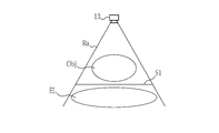
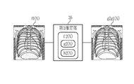
- the radiography system 10 includes a radiation source 13, a radiography panel 14, a console 20, and a radiographic image processing apparatus 30.
- the radiation imaging system 10 irradiates the radiation imaging panel 14 with radiation emitted from a radiation source 13 such as an X-ray source and transmitted through the subject Obj, so that the radiation of the subject Obj lying on the imaging table 18 (see FIG. 2) is emitted. Get an image. As a result, the range of radiation emitted to the subject Obj is defined.
- the radiographic image is input to the console 20.
- the radiation source 13, the radiography panel 14, and the console 20 constitute a radiography apparatus.
- the radiation source 13 is a device that generates radiation Ra necessary for imaging, and is derived from a radiation tube that generates radiation Ra, a high voltage generation circuit that generates high voltage required for the radiation tube to generate radiation Ra, and the like. Become.
- the radiation source 13 can generate a plurality of types of radiation having different radiation qualities (energy distribution with respect to wavelength (hereinafter, simply referred to as energy)) by adjusting the tube voltage, tube current, and the like of the radiation tube.
- the energy of the radiation generated by the radiation source 13 is one of the imaging conditions.
- the radiation source 13 is an X-ray source that generates X-rays. Therefore, the radiographic imaging system 10 is an X-ray imaging system that acquires an X-ray image of the subject Obj by photographing the subject Obj using X-rays.
- the subject Obj is, for example, a person.
- the radiation photographing panel 14 is a radiation detector that photographs the subject Obj using the radiation Ra generated by the radiation source 13.
- the radiography panel 14 is a so-called FPD (Flat Panel Detector), and outputs a radiographic image of the subject Obj by detecting the radiation Ra transmitted through the subject Obj and converting it into an electric signal.
- the radiography panel 14 is preferably portable.
- the radiation photographing panel 14 is detachably attached to the photographing table 18 together with the following grid and the like by the mounting portion provided on the lower surface of the photographing table 18 (see FIG. 2).
- the radiography panel 14 may be fixed to the imaging table 18.
- the grid is a device for removing scattered radiation components of radiation, for example, a stationary Lisholm blender, a mobile Bucky blender, or the like.
- the grid is composed of lead and the like that do not transmit radiation and interspace materials such as aluminum and fibers that easily transmit radiation, which are alternately arranged at a fine grid density of, for example, about 4.0 lines / mm. ..
- the scattered radiation component of the radiation transmitted through the subject Obj can be removed, but it cannot be completely removed. Therefore, the radiation image acquired by the radiography panel 14 includes not only the primary ray component of the radiation transmitted through the subject Obj but also the scattered ray component.
- the radiography panel 14 includes two radiation detectors, a first radiation detector 15 and a second radiation detector 16.
- the first radiation detector 15 and the second radiation detector 16 the detector arranged relatively close to the subject Obj and the radiation source 13 is the first radiation detector 15, which is relative to the subject Obj and the radiation source 13.
- the second radiation detector 16 is a detector that is arranged as far away as possible.
- the first radiation detector 15 and the second radiation detector 16 detect the radiation Ra transmitted through the subject Obj for each pixel. Further, the first radiation detector 15 and the second radiation detector 16 output a radiation image of the subject Obj to each of them.
- the radiography panel 14 includes a radiation energy conversion filter 17 between the first radiation detector 15 and the second radiation detector 16.
- the radiation energy conversion filter 17 is, for example, a copper plate or the like, and absorbs a low energy component of radiation Ra. Therefore, the energy of the radiation Ra changes after passing through the first radiation detector 15 and before reaching the second radiation detector 16. Therefore, the radiation photographing panel 14 simultaneously photographs a specific subject Obj under the same imaging conditions (same radiation Ra), but the radiation image G1 output by the first radiation detector 15 and the radiation output by the second radiation detector 16
- the image G2 is a radiation image in which the energies of the radiation Ra used for photographing are substantially different from each other.
- the first radiation detector 15 or the second radiation detector 16 is preferably one that can repeatedly record and read a radiation image.
- the first radiation detector 15 and the second radiation detector 16 may be either an indirect conversion type detector or a direct conversion type detector, and the first radiation detector 15 and the second radiation detector 16 are different types.
- the detector can be adopted.
- the indirect conversion type detector is a detector that indirectly obtains an electric signal by converting radiation Ra into visible light using a scintillator made of CsI (cesium iodide) or the like and photoelectrically converting the visible light. Is.
- the direct conversion type detector is a detector that directly converts radiation Ra into an electric signal using a scintillator made of amorphous selenium or the like.
- the first radiation detector 15 and the second radiation detector 16 may be PSS (Penetration Side Sampling) type detectors or ISS (Irradiation Side Sampling) type detectors, respectively.
- the PSS method is a method in which a scintillator is arranged on the subject Obj side with respect to a TFT (Thin Film Transistor) that reads out an electric signal.
- the ISS method is a method in which the scintillator and the TFT are arranged in the order of the TFT and the scintillator from the subject Obj side.
- the console 20 is a control device (computer) that controls the operations of the radiation source 13 and the radiography panel 14, and includes a display 21, an operation unit 22, and the like.
- the display 21 is, for example, a liquid crystal display or the like, and displays a radiographic image taken and other necessary displays related to operations or settings.
- the operation unit 22 is, for example, a keyboard and / or a pointing device used for setting input of imaging conditions and the like and operating the radiation source 13 and the radiation imaging panel 14.
- the display 21 and the operation unit 22 can be configured by a touch panel.
- the radiation image processing device 30 performs image processing using a radiation image obtained by capturing a subject Obj for display in diagnosis or the like or for detailed image analysis or the like related to diagnosis or the like.
- the radiation image processing device 30 can be directly connected to the console 20 to acquire a radiation image of the subject Obj in real time and use it for image processing.
- RIS Radiology Information Systems
- HIS Hospital Information Systems
- PACS Picture Archiving and Communication Systems
- DICOM included in PACS ( Digital Imaging and Communications in Medicine) Radiation images can be indirectly acquired via a server or the like and used for image processing.
- the subject Obj there is an element through which the radiation Ra passes after passing through the subject Obj.
- the subject Obj may be arranged on the shooting table 18 for shooting.
- the top plate 19 of the photographing table 18 is an element through which the radiation Ra passes after passing the subject Obj.
- the layer) and the like are elements through which the radiation Ra passes after passing through the subject Obj.
- Each of these elements is an additional device component for the convenience of imaging, and each absorbs and scatters radiation in no small measure. Therefore, in the present embodiment, the above elements are collectively referred to as an additional scattering element EL (see FIG. 4).
- passing means passing through the subject Obj or the additional scattering element EL, etc., transmitting through the subject Obj or the additional scattering element EL, etc., and passing through the subject Obj or the additional scattering element EL, etc. Includes passing through in a direction different from the incident direction due to the scattering of.
- transmission means passing through the subject Obj or the additional scattering element EL in the incident direction, and is substantially incident in a state where some components are absorbed by the subject Obj or the additional scattering element EL or the like. Including passing through along the direction.
- scattering means passing through the subject Obj, the additional scattering element EL, or the like in a direction different from the incident direction.
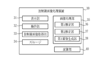
- the radiation image processing device 30 is a so-called computer, and includes a display 31, an operation unit 32, a radiation image acquisition unit 33, an image processing unit 35, and a calculation unit 40.
- programs related to various processes are incorporated in the program memory.
- the functions of the radiation image acquisition unit 33, the image processing unit 35, and the calculation unit are realized by operating the program in the program memory by the central control unit (not shown) configured by the processor.
- the functions of the first estimation unit 36, the second estimation unit 37, and the first image generation unit 38 included in the image processing unit 35 are realized.
- the display 31 is a liquid crystal display or the like, and displays a photographed radiation image and an image generated by the radiation image processing device 30.
- the operation unit 32 is a keyboard and / or a pointing device for operating the radiographic image processing device 30.
- the display 31 and the operation unit 32 can be configured by a touch panel.
- the radiation image processing device 30 is a device separate from the console 20, but a part or all of the radiation image processing device 30 can be provided on the console 20.
- the display 21 and / or the operation unit 22 of the console 20 can be used as the display 31 and / or the operation unit 32 of the radiation image processing device 30.
- the console 20 constitutes the radiation image processing apparatus 30.
- the radiation image acquisition unit 33 acquires a radiation image obtained by photographing the subject Obj using radiation Ra.
- the radiographic image acquisition unit 33 can acquire a radiological image from the console 20, RIS, HIS, PACS, or the like. In the present embodiment, the radiographic image acquisition unit 33 directly acquires the radiological image captured by the radiographic imaging system 10 from the console 20. Further, the radiation image acquisition unit 33 acquires the radiation image G1 output by the first radiation detector 15 and the radiation image G2 output by the second radiation detector 16. When acquiring a radiation image, the radiation image acquisition unit 33 performs not only a so-called original image (an image that has not been subjected to image processing or the like) but also various processing such as contrast adjustment processing or other image processing. Radiation image may be acquired.
- the image processing unit 35 generates a radiographic image.
- the radiation image generated by the image processing unit 35 is an image in which an image of the subject is formed by the radiation Ra transmitted through the subject Obj and the additional scattering element EL. That is, the radiation image generated by the image processing unit 35 is the radiation Ra that is scattered by the subject Obj and / or the additional scattering element EL with respect to the captured radiation image (radiation image acquired by the radiation image acquisition unit 33). It is a scattered radiation component reduction image which reduced the component (scattered radiation component) of. Therefore, the image processing unit 35 includes a first estimation unit 36, a second estimation unit 37, and a first image generation unit 38.
- the photographed radiation image is referred to as a first radiation image 51 (see FIG. 5) and is generated by the image processing unit 35.
- the radiographic image is called a second radiological image (not shown).
- the first estimation unit 36 estimates the component of the radiation Ra that has passed through the subject Obj using the first radiation image 51.
- the "radiation Ra that has passed through the subject Obj” is defined as that after the subject Obj has passed and that the additional scattering element EL such as the top plate 19 is used.
- the component of the radiation Ra that has passed through the subject Obj specifically means a component in which the radiation Ra has passed through the subject Obj and / or a component of the radiation Ra in which the subject Obj is scattered. That is, the component through which the radiation Ra has passed through the subject Obj is a so-called primary line component after passing through the subject Obj.
- the component of the radiation Ra scattered by the subject Obj is a so-called scattered ray component after passing through the subject Obj.
- the subject Obj is regarded as an operator g1 that generates a primary line and an operator h1 that generates a scattered ray component, as shown in FIG. 5, the subject The primary ray component after passing through Obj is "g1 (X)", and the scattered ray component after passing through the subject Obj is "h1 (X)".
- the first estimation unit 36 uses the primary line component g1 (X) after passing through the subject Obj, the scattered line component h1 (X) after passing through the subject Obj, or both of them. Can be estimated.
- the first estimation unit 36 uses the first radiation image 51 to form a primary line component g1 (X) after passing through the subject Obj and a scattered line component h1 (X) after passing through the subject Obj. , Are estimated respectively.
- the first estimation unit 36 estimates the primary line component g1 (X) after passing through the subject Obj from the first radiation image 51.
- the first estimation unit 36 estimates the primary radiation image 51 from the first radiation image 51.
- the scattered line component h1 (X) after passing through the subject Obj can be estimated.
- the first estimation unit 36 estimates the scattered radiation component h1 (X) after passing through the subject Obj from the first radiation image 51.
- the primary line component g1 (X) after passing through the subject Obj can be estimated.
- the body thickness of the subject Obj is estimated using the first radiation image 51, and the body thickness of the estimated subject Obj is used to pass through the subject Obj. This can be done by estimating the components of the radiation Ra.
- the first estimation unit 36 determines the subject Obj by the radiation Ra for each pixel of the first radiation image 51 (or for each predetermined section composed of a plurality of pixels) based on the estimated body thickness of the subject Obj.
- the transmitted primary line component g1 (X) and the scattered line component h1 (X) of the radiation Ra scattered by the subject Obj are estimated.
- the pixel value V1 when there is no subject Obj is the pixel value of the region (direct region) where the radiation Ra reaches the radiation photographing panel 14 without passing through the subject Obj, or the experiment performed in advance (photographing without the subject Obj). ) Etc. can be known. Therefore, the first estimation unit 36 can estimate the body thickness of the subject Obj from the pixel value V2 of the first radiation image 51 taken with the subject Obj placed.
- the primary line component g1 (X) and the scattered line component h1 (X) after passing through the subject Obj are both related to the body thickness of the subject Obj.
- the primary line component g1 (X) decreases due to absorption of the subject Obj and the like, and the scattered ray component h1 (X) increases with respect to the incident radiation Ra.
- the properties of the subject Obj that is, the amount of transmission and the amount of scattering of the subject Obj with respect to the radiation Ra having a specific energy can be obtained in advance by an experiment or the like before radiography.
- the first estimation unit 36 sets the characteristics related to the transmission amount and the scattering amount (hereinafter referred to as the subject scattering characteristics) for each subject Obj or for each photographing portion of the subject Obj as a function or a conversion table or the like. Keep in format. Then, by using the energy of the radiation Ra used for photographing and the estimated body thickness of the actual subject Obj to obtain the transmission amount and the scattering amount of the radiation Ra, the primary line after passing through the subject Obj. The component g1 (X) and the scattered radiation component h1 (X) are estimated.
- the estimation results output by the first estimation unit 36 are the primary line component g1 (X) at the position S1 after passing the subject Obj and the scattered line component h1 at the position S1 after passing the subject Obj. (X) or the intensity distribution f1 (X) of the radiation Ra at the position S1 after passing the subject Obj.
- the intensity distribution f1 (X) of the radiation Ra at the position S1 is, for example, the sum or weighted sum of the primary line component g1 (X) and the scattered line component h1 (X). In the present embodiment, as shown in FIG.
- the first estimation unit 36 sets the intensity distribution f1 (X) of the radiation Ra at the position S1 after passing the subject Obj, for example, an image format or data capable of constructing an image. It is output as the first estimation result in the form of an aggregate of.
- the first estimation unit 36 can also output either the primary line component g1 (X) or the scattered line component h1 (X) after passing through the subject Obj as the estimation result.
- the second estimation unit 37 passed through the additional scattering element EL by using the estimation result of the first estimation unit 36 and the scattering characteristics of the additional scattering element EL through which the radiation Ra passes after passing the subject. Estimate the components of radiation Ra.
- "passing through the additional scattering element EL” means that the subject Obj has passed a certain position and then the additional scattering element EL. It means that it has passed. Therefore, depending on the specific shape of the subject Obj, the subject Obj is not transmitted and directly passes through the additional scattering element EL.
- the component in which the radiation Ra has passed through the subject Obj and the additional scattering element EL, or the radiation Ra in which at least one of the subject Obj or the additional scattering element EL is scattered Estimate the components.
- the component in which the radiation Ra has passed through the subject Obj and the additional scattering element EL is a so-called primary line component after passing through the additional scattering element EL.
- the component of the radiation Ra scattered by at least one of the subject Obj and the additional scattering element EL is a so-called scattered ray component after passing through the additional scattering element EL.
- the scattering characteristics of the additional scattering element EL determine the distribution of the radiation amount transmitted through the additional scattering element EL and / or the radiation amount scattered by the additional scattering element EL.
- the first characteristic g2 (X) is a function or a conversion table or the like that determines the transmitted dose of the radiation Ra directly incident on the additional scattering element EL toward an arbitrary position X without going through the subject Obj.
- the second characteristic h2 (X) is a function or a conversion table for determining the transmitted dose of the radiation Ra directly incident on the additional scattering element EL toward an arbitrary position X without going through the subject Obj. ..
- the additional scattering element EL is only the top plate 19 of the photographing table 18, the first characteristic g2 (X) determines the distribution of the transmitted dose of the top plate 19, and the second characteristic h2 (X) is the top plate. Determine the distribution of the 19 scattered doses.
- the state of the specific configuration of the additional scattering element EL (use or non-use of the imaging table 18 or the like) is known before radiography. Therefore, the first characteristic g2 (X) and the second characteristic h2 (X) are obtained in advance by experiments or the like, for example, for each specific configuration of the additional scattering element EL or for each combination of the additional scattering element EL. be able to. Further, if the additional scattering element EL is considered to generate a primary ray component and a scattered radiation component from the incident radiation, the first characteristic g2 (X) is a primary ray component corresponding to the incident radiation. It is an operator to be generated, and the second characteristic h2 (X) is an operator to generate a scattered radiation component according to the incident radiation.
- the second estimation unit 37 has the first characteristic g2 (X) and the second characteristic h2 (X) in advance for each specific configuration of the additional scattering element EL, for example.
- the second estimation unit 37 possesses the scattering characteristic f2 (X) of the additional scattering element EL in advance.
- the second estimation unit 37 can acquire the first characteristic g2 (X), the second characteristic h2 (X), and / or the scattering characteristic f2 (X), if necessary.
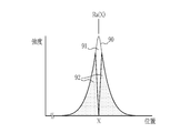
- the intensity distribution after the radiation Ra (X) incident toward an arbitrary point X has passed through the additional scattering element EL is approximated by the PSF (point spread function) 90.
- the PSF90 is, for example, a Gaussian function.
- the component reaching the arbitrary point X and its vicinity is the distribution 91 of the primary line component, and this is from PSF90.
- the portion excluding the distribution 91 of the primary radiation component is the distribution 92 of the scattered radiation component.
- the second characteristic h2 (X) is obtained by performing the deconvolution calculation of the distribution 92 of the scattered radiation component on the radiation image obtained by taking a picture without placing the subject Obj. It can be obtained in advance. Further, the first characteristic g2 (X) can be obtained in advance by subtracting the second characteristic h2 (X) from the same radiation image or by performing the deconvolution calculation of the distribution 91 of the primary line component. it can.
- g2g1 (X) in the first term on the right side of the above formula 3 transmits the subject Obj and the additional scattering element EL among the radiation Ra used for photographing.
- the second term “g2h1 (X)” on the right side of the equation 3 is scattered by the scatterer A1 included in the subject Obj among the radiation Ra used for photographing, and then is transmitted through the additional scattering element EL to be arbitrary. It represents the radiation Ra2 that reaches the pixel P (X) at the point X.
- the third term "h2g1 (X)" on the right-hand side of Equation 3 is any radiation Ra used for photographing, which is transmitted through the subject Obj and then scattered by the scatterer B1 included in the additional scattering element EL. Represents the radiation Ra3 reaching the pixel P (X) at point X. Further, “h2h1 (X)” in the fourth term on the right side of Equation 3 is scattered by the scatterer A2 included in the subject Obj among the radiation Ra used for photographing, and then the scatterer B2 included in the additional scattering element EL. Represents the radiation Ra4 which is further scattered by and reaches the pixel P (X) at an arbitrary point X.
- the second estimation unit 37 obtains the first term "g2g1 (X)” of the mathematical formula 3 and / or the sum "g2h1 (X) + h2g1 (X) + h2h1 (X)” of the second to fourth terms. ..
- the first term “g2g1 (X)” of the formula 3 represents the distribution of the primary line component after passing through the additional scattering element EL
- the sum of the second to fourth terms "g2h1 (X) + h2g1 (X) + h2h1 ( This is because "X)" represents the distribution of the scattered radiation component after passing through the additional scattering element EL.
- the second estimation unit 37 obtains the distribution (g2g1 (X)) of the primary line component after passing through the additional scattering element EL, and outputs this as the estimation result.
- the first image generation unit 38 uses the estimation result of the second estimation unit 37 to generate a second radiation image that forms an image of the subject by the radiation Ra transmitted through the subject Obj and the additional scattering element EL.
- the first image generation unit 38 is the second estimation result of the second estimation unit 37.
- a second radiographic image is generated by imaging the estimation result.
- the second estimation unit 37 estimates the scattered radiation component in which the subject Obj or the additional scattering element EL scatters the radiation Ra
- the first image generation unit 38 performs the first radiation image 51 to the second estimation unit 37.
- a second radiographic image is generated by subtracting the second estimation result, which is the estimation result of.
- the second estimation unit 37 outputs the distribution of the primary line component after passing through the additional scattering element EL, and the first image generation unit 38 visualizes this to obtain a second radiation image.
- the distribution “g2g1 (X)” of the primary line component output by the second estimation unit 37 is substantially the second radiation image.
- the first image generation unit 38 can perform various image processings (for example, contrast adjustment processing, structure enhancement processing, etc.) on the generated second radiation image, if necessary.
- the calculation unit 40 performs a calculation using the second radiation image output by the image processing unit 35.
- the calculation unit 40 uses the second radiation image generated by using the radiation image G1 obtained from the first radiation detector 15 and the second radiation generated by using the radiation image G2 obtained from the second radiation detector 16.
- An image and a so-called subtraction image are generated using.
- the subtraction image is an emphasized image that emphasizes a specific structure included in the subject Obj, and is a radiation image obtained by multiplying each pixel or each recognized structure by an attenuation coefficient ⁇ of the structure. It is generated by performing subtraction processing.
- both of the two second radiation images used for the subtraction processing substantially consist of the distribution of the primary ray component (g2g1 (X)), and the scattered ray component is reduced with high accuracy. Therefore, as a result, the error due to the scattered radiation component is small even after the subtraction treatment. Therefore, a particular structure can be emphasized particularly accurately.
- the calculation unit 40 can perform a calculation other than the subtraction process. For example, the calculation unit 40 can obtain numerical values related to the composition of the subject Obj, such as the amount of bone mineral, using a plurality of second radiation images. In this case, by using the second radiation image, the pixel value with the scattered radiation component reduced with high accuracy can be used for the calculation, so the bone mineral content etc. can be calculated more accurately than when this is not used. it can.
- the radiation image acquisition unit 33 acquires the first radiation image 51, which is a radiation image obtained by photographing the subject Obj using the radiation Ra (step S101 (radiation image acquisition step)).
- the radiation image G1 taken by using the first radiation detector 15 and the radiation image G2 taken by using the second radiation detector 16 are acquired as the first radiation image 51.
- the first estimation unit 36 performs the first estimation process on each of the first radiation images. Specifically, the first estimation unit 36 estimates the body thickness of the subject Obj using the first radiation image 51 (step S102). Then, using the estimated body thickness of the subject Obj, the intensity distribution f1 (X) of the radiation Ra after passing through the subject Obj is estimated (step S103). In the first estimation unit 36, the intensity distribution f1 (X) of the radiation Ra after passing through the subject Obj is such that the primary line component g1 (X) after passing through the subject Obj and the scattered ray component h1 (X) after passing through the subject Obj. And, and it is calculated by adding up these.
- the step S102 for estimating the body thickness and the step S103 for obtaining the intensity distribution f1 (X) of the radiation Ra after passing through the subject Obj constitute the first estimation step.
- the second estimation unit 37 estimates the component of the radiation Ra after passing through the additional scattering element EL such as the top plate 19 (step S104 (second estimation step)). For example, the second estimation unit 37 causes the intensity distribution f1 (X) of the radiation Ra after passing through the subject Obj to act on the first characteristic g2 (X) that determines the distribution of the radiation amount transmitted through the additional scattering element EL. The distribution (g2g1 (X)) of the primary line component after passing through the additional scattering element EL is calculated. Then, the first image generation unit 38 generates a second radiation image by imaging the distribution (g2g1 (X)) of the primary line component after passing through the additional scattering element EL (step S105 (image). Generation step)).
- the first estimation unit 36 estimates the intensity distribution f1 (X) of the radiation Ra after passing through the subject Obj, and then the second estimation unit 37 estimates the intensity distribution f1.
- the distribution (g2g1 (X)) of the primary line component after passing through the additional scattering element EL is obtained.
- the first image generation unit 38 generates a second radiation image by imaging the image, and is used for display on the display 31 or the like and / or calculation in the calculation unit 40. That is, since the second radiation image is a radiation image generated through the first estimation process and the second estimation process stepwise, it is different from the conventional radiation image (particularly the radiation image in which the scattered radiation component is reduced by the conventional method). In comparison, the scattered radiation component can be reduced with high accuracy. That is, the radiation image processing apparatus 30 can reduce the scattered radiation component of the radiation image more accurately than before by the image processing.
- the first radiation image is included in the first radiation image by deconvolving the distribution 92 of the scattered radiation component excluding the distribution 91 of the primary line component from the PSF 90.
- the scattered radiation component may be reduced.
- the first conventional method is the third of the mathematical formula 3 related to the second characteristic h2 (X). It is close to the process excluding the term (g2h1 (X)) and the fourth term (h2h1 (X)). That is, the first conventional method of reducing the scattered radiation component cannot remove the scattered radiation component of the second term (g2h1 (X)) of Equation 3.
- the scattered radiation component can be reduced with higher accuracy than the first conventional method of reducing the scattered radiation component. This is because the scattered radiation component of the second term (g2h1 (X)) of the mathematical formula 3 can be reduced, and the primary ray component of the first term (g2g1 (X)) of the mathematical formula 3 can be accurately estimated.
- a radiation image with a reduced scattered radiation component may be obtained based on the estimation result of the body thickness of the subject Obj. That is, the primary line component g1 (X) after passing through the subject Obj may be used as a radiation image with the scattered line component reduced.
- the primary line component g1 (X) after passing through the subject Obj reduces the scattered line component h1 (X) after passing through the subject Obj after comparing with the original first radiation image 51.
- the first radiation image is an image formed by the radiation Ra that has passed not only the subject Obj but also the additional scattering element EL.
- the primary line component g1 (X) after passing through the subject Obj contains a scattered line component potentially due to the additional scattering element EL.
- the second conventional method has a scattered radiation component h1 (X) after passing through the subject Obj. ) Is similar to the process of reducing the second term (g2h1 (X)) and the fourth term (h2h1 (X)) of the mathematical formula 3. Therefore, according to the radiation image processing apparatus 30, the scattered radiation component can be reduced with higher accuracy than the second conventional method of reducing the scattered radiation component. This is because the scattered radiation component of the third term (h2g1 (X)) of the mathematical formula 3 can be reduced, and the primary ray component of the first term (g2g1 (X)) of the mathematical formula 3 can be accurately estimated.
- the radiation image processing apparatus 30 uses the same processing method for the second radiation as long as the scattering characteristic f2 (X) of the additional scattering element EL is obtained in advance, even if the radiography apparatus is changed. Images can be generated. Then, the scattering characteristic f2 (X) of the additional scattering element EL can be obtained, for example, by simply taking a radiographic image without placing the subject Obj and without performing excessive trial and error. Therefore, the scattering ray component reduction processing by the method of performing the first estimation processing and the second estimation processing stepwise can obtain accurate results regardless of the photographing apparatus and the photographing environment.
- the first estimation unit 36 estimates the primary component in which the radiation Ra has passed through the subject Obj and the scattered ray component of the radiation Ra scattered by the subject Obj.
- the primary line component and the scattered line component after passing through the subject Obj can be accurately estimated.
- the accuracy of the second estimation process is improved, and the accuracy of reducing the scattered radiation component in the second radiation image is improved.
- the first estimation unit 36 estimates the body thickness of the subject Obj using the first radiation image 51, and the radiation Ra that has passed through the subject Obj using the estimated body thickness of the subject Obj. Estimate the components of. By estimating the body thickness of the subject Obj in this way and using this, the first estimation unit 36 can estimate the component of the radiation Ra after passing through the subject Obj with particularly high accuracy. Further, in the above embodiment, the first estimation unit 36 includes a primary line component in which the radiation Ra has passed through the subject Obj and a scattered line of the radiation Ra scattered by the subject Obj based on the estimated body thickness of the subject Obj. Estimate the components. By using the estimated body thickness for estimating the primary line component and the scattered line component after passing through the subject Obj, the first estimation unit 36 can perform these estimations with particularly high accuracy. ..
- the first estimation result which is the estimation result of the first estimation unit 36, is the intensity distribution f1 (X) of the radiation Ra that has passed through the subject Obj
- this intensity distribution f1 (X) is
- the radiation Ra includes a primary ray component (g1 (X)) that has passed through the subject Obj, and a scattered ray component (h1 (X)) of the radiation Ra that the subject Obj has scattered. Therefore, in the second estimation process using the first estimation result, all of the terms in the mathematical formula 3 can be accurately obtained. As a result, the primary ray component and the scattered ray component in the second estimation process are accurate.
- the second estimation unit 37 uses the primary line component (that is, the first term in Equation 3) in which the radiation Ra has passed through the subject Obj and the additional scattering element EL, or the subject Obj or the additional scattering element.
- the scattered radiation component of the radiation Ra scattered by at least one of the ELs (that is, the second to fourth terms in Equation 3) is estimated. Therefore, a highly accurate estimation result can be obtained.
- the second estimation unit 37 causes the scattering characteristic f2 (X) of the additional scattering element EL to act on the first estimation result which is the estimation result of the first estimation unit 36, thereby causing the additional scattering element.
- the component of the radiation Ra that has passed through the EL is estimated. That is, in the second estimation process, it is taken into consideration that the radiation Ra incident on the additional scattering element EL is the radiation Ra after passing through the subject Obj. Therefore, the accuracy of the second estimation result is high.
- the scattering characteristic f2 (X) of the additional scattering element EL specifically determines the distribution of the radiation amount transmitted through the additional scattering element EL and / or the radiation amount scattered by the additional scattering element EL. It is to be decided. Therefore, in the second estimation process, the component of the radiation Ra after passing through the additional scattering element EL can be estimated with high accuracy from the first estimation result.
- the scattering characteristic f2 (X) of the additional scattering element EL includes the first characteristic g2 (X) that determines the distribution of the radiation amount transmitted through the additional scattering element EL and the additional scattering. It includes a second characteristic h2 (X) that determines the distribution of the radiation amount scattered by the element EL. Therefore, in the second estimation process, an accurate estimation result is obtained in which the distribution of the radiation amount transmitted through the additional scattering element EL and the distribution of the radiation amount scattered by the additional scattering element EL are accurately considered. Can be done.
- the radiation Ra passes through the subject Obj and the additional scattering element EL, but the additional scattering element EL is subdivided and each element is considered individually. can do.
- the additional scattering element EL is subdivided and each element is considered individually. can do.
- g2a (X) is the first characteristic of the gel mat
- h2a (X) is the second characteristic of the gel mat
- g2b (X) is the first characteristic of the top plate 19
- h2b (X) is the second characteristic of the top plate 19.
- the mathematical formula 1 of the above embodiment can be extended to f2b (f2a (f1 (X))). That is, in the second estimation unit 37, the radiation Ra determines the scattering characteristic f2a (X) of the gel mat and the scattering characteristic f2b (X) of the top plate 19 with respect to the first estimation result (f1 (X)).
- the primary line component (g2bg2af1 (X)) transmitted through the subject Obj, the gel mat, and the top plate 19 can be estimated.
- the number of additional scattering elements EL is 3 or more
- the second estimation unit 37 has a scattering characteristic of each additional scattering element with respect to the first estimation result (f1 (X)) in the order in which the radiation Ra passes.
- the radiation Ra passes through the subject Obj first, but the scattered radiation reduction processing of the radiation image processing apparatus 30 is extended even when there is an additional scattering element EL between the radiation source 13 and the subject Obj.
- g0 (X) is the first characteristic of the pre-scattering element before the subject Obj
- h0 (X) is the second characteristic of the pre-scattering element before the subject Obj.
- the first estimation unit 36 obtains the first estimation result (f1 (X)) from the first radiation image 51, it is assumed that the radiation that has passed through the pre-scattering element of the scattering characteristic f0 (X) is incident. , Obtain the first estimation result. That is, as a whole, the mathematical formula 1 of the above embodiment is extended to f2 (f1 (f0 (X))). As a result, even when there is a pre-scattering element in front of the subject Obj, it is possible to obtain a second radiation image in which the scattered radiation component is accurately reduced.
- the content of the specific estimation process of the primary line component and the scattered ray component in the above embodiment and the like is an example, and the estimation process of the primary line component and the scattered ray component of another aspect is applied to the above embodiment and the like. It can be applied step by step.
- the radiation image processing device 30 in the above-described embodiment or the like can use an arbitrary subject Obj (including the case where it is an animal or an object) and a radiation image obtained by photographing an imaged portion of the arbitrary subject Obj.
- the radiation image acquisition unit 33 uses the step of acquiring the first radiation image 51 in which the subject Obj is photographed using the radiation Ra, and the first estimation unit 36 uses the first radiation image 51. Then, the step of estimating the component of the radiation Ra that has passed through the subject Obj, the estimation result of the first estimation unit 36 by the second estimation unit 37, and the additional scattering element EL that the radiation Ra further passes through after passing through the subject Obj.
- the scattering characteristic f2 (X) of the above the step of estimating the component of the radiation Ra that has passed through the additional scattering element EL, and the first image generation unit 38 using the estimation result of the second estimation unit 37.
- a radiation image processing method comprising the step of generating a second radiation image forming an image of the subject Obj by radiation Ra transmitted through the subject Obj and the additional scattering element EL.
- a radiation image acquisition step of acquiring a first radiation image 51 in which the subject Obj is photographed using radiation Ra using a computer or a part of a component of the computer and a radiation image acquisition step of acquiring the first radiation image 51, and the subject Obj using the first radiation image 51.
- the first estimation step for estimating the component of the radiation Ra that has passed through the radiation Ra, the estimation result of the first estimation step, and the scattering characteristic f2 (X) of the additional scattering element EL that the radiation Ra further passes after passing through the subject Ra.
- the second estimation step of estimating the component of the radiation Ra that has passed through the additional scattering element EL and the estimation result of the second estimation step are used to use the radiation Ra that has passed through the subject Obj and the additional scattering element EL.
- a program that executes an image generation step of generating a second radiation image that forms an image of the subject Obj constitutes a radiation image processing apparatus 30.
- the radiographic image processing apparatus 100 shown in FIG. 12 is used instead of the radiographic image processing apparatus 30 of the first embodiment.
- the radiation image processing apparatus 100 includes a radiation image acquisition unit 33, an imaging condition acquisition unit 102, a body thickness derivation unit 103, a characteristic acquisition unit 104, a line distribution derivation unit 105, and a second image generation unit 106.
- the radiographic image processing apparatus of the present invention may have both the functions of the radiographic image processing apparatus 30 of the first embodiment and the functions of the radiographic image processing apparatus 100 of the second embodiment.
- a central control unit (not shown) composed of a processor executes a program in the program memory to execute a radiation image acquisition unit 33, an imaging condition acquisition unit 102, a body thickness derivation unit 103, a characteristic acquisition unit 104, and a line distribution.
- the functions of the derivation unit 105 and the second image generation unit 106 are realized.
- the radiation image acquisition unit 33 drives the radiation source 13 to irradiate the subject Obj with radiation, detects the radiation transmitted through the subject Obj by the radiation photographing panel 14, and acquires the radiation image G0 of the subject Obj.
- the top plate 19 of the photographing table 18 and the grid 110 are interposed between the subject Obj and the radiation photographing panel 14. Therefore, the radiation transmitted through the subject Obj is transmitted through the top plate 19 and the grid 110 and irradiated to the radiography panel 14.
- the grid 110 it is preferable to use the one described in the first embodiment.
- the radiation quality is defined by using one or more of the tube voltage [kV] of the radiation generator at the radiation source 13, the total filtration amount [mmAI equivalent], and the half-value layer [mmAI].
- the tube voltage means the maximum value of the generated radiation energy distribution.
- the total filtration amount is obtained by converting the filtration amount of each component constituting the radiation generator, collimator, etc. in the radiation source 13 into the thickness of aluminum. The larger the total filtration amount, the greater the influence of beam hardening, and the more high-energy components in the wavelength distribution of radiation.
- the half-value layer is defined by the thickness of aluminum required to attenuate the dose in half with respect to the generated radiation energy distribution. The thicker the aluminum in the half-value layer, the more high-energy components in the wavelength distribution of radiation.
- the dose is defined using either the tube current-time product [mAs] of the radiation generator at the radiation source 13 or the irradiation dose [mR].
- the SID is the distance [cm] between the radiation source 13 and the radiography panel 14.
- the shooting conditions are set according to the shooting technique. Therefore, in the present embodiment, a table in which various shooting techniques and shooting conditions are associated with each other is stored in the storage 34 in advance. At the time of shooting, when the operator specifies the shooting technique input from the operation unit 32, the table stored in the storage 34 is referred to, and the shooting conditions corresponding to the shooting technique are read out from the table and read out. The subject Obj will be photographed according to the photographing conditions. The shooting conditions used at the time of shooting are temporarily stored in the storage 34. The shooting conditions are not limited to those according to the shooting technique, and may be specified by the operator inputting using the operation unit 32.
- the shooting condition acquisition unit 102 acquires the shooting conditions used when shooting the subject by reading them from the storage 34.
- the body thickness derivation unit 103 derives the body thickness distribution of the subject Obj based on the radiation image G0 and the imaging conditions.
- the body thickness distribution derived by the body thickness derivation unit 103 will be referred to as an initial body thickness distribution t0.
- the derivation of the initial body thickness distribution t0 will be described.
- the reaching dose I0 (x, y) of the radiation emitted from the radiation source 13 to the radiation imaging panel 14 is reached.
- mAs included in the imaging conditions is the tube current time product
- kV is the tube voltage.
- F is the amount of radiation that reaches the radiography panel 14 when the radiography panel 14 is irradiated with the reference dose (for example, 1 mAs) at the reference SID (for example, 100 cm) without the subject Obj. It is a non-linear function that represents. F changes for each tube voltage or depending on the tube voltage and the half-value layer. Further, since the reaching dose I0 is derived for each pixel of the radiographic image acquired by the radiography panel 14, (x, y) represents the pixel position of each pixel. Further, in the following description, in order to include both the case where the half-value layer is considered and the case where it is not considered, by including mmAI in parentheses in each formula as shown in the following formula (X1-2). It shall be represented.
- I0 (x, y) mAs ⁇ F (kV) / SID 2 (X1)
- I0 (x, y) mAs ⁇ F (kV, mmAl) / SID 2 (X1-1)
- I0 (x, y) mAs ⁇ F (kV (, mmAl)) / SID 2 (X1-2)
- the initial body thickness distribution is t0
- the attenuation coefficient of the subject Obj having the initial body thickness distribution t0 is ⁇ (t0)
- the Scatter-to-Primary Ratio which is the ratio of the scattered dose contained in the transmitted radiation to the primary dose
- STPR (t0) the dose I1 after passing through the subject Obj is expressed by the following formula (X2).
- the initial body thickness distribution t0, the reached dose I0, and the dose I1 are derived for each pixel of the radiographic image G0, but (x, y) are omitted.
- STPR is a non-linear function that depends not only on the body thickness but also on the tube voltage [kV] and the half-value layer [mmAI], but in the equation (X2), the kV and mmAI notations are omitted.
- I1 I0 ⁇ exp ⁇ - ⁇ (t0) ⁇ t0 ⁇ ⁇ ⁇ 1 + STPR (t0) ⁇ (X2)
- the dose I1 is a pixel value in each pixel of the radiation image G0, and the reached dose I0 is derived by the above formulas (X1) and (X1-1).
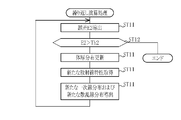
- equation (X2) cannot be algebraically solved for t0. Therefore, the body thickness derivation unit 103 defines the error function E1 shown in the following equation (X3) or equation (X3-1). Then, the error function E1 is minimized, or t0 at which the error function E1 is less than the predetermined threshold value Th1 is derived as the initial body thickness distribution.
- the body thickness derivation unit 103 derives the initial body thickness distribution t0 by using an optimization algorithm such as the steepest descent method and the conjugate gradient method.
- E1 [I1-I0 ⁇ exp ⁇ - ⁇ (t0) ⁇ t0 ⁇ ⁇ ⁇ 1 + STPR (t0) ⁇ ] 2 (X3)
- E1
- the characteristic acquisition unit 104 acquires the radiation characteristics of the element interposed between the subject Obj and the radiation imaging panel 14 at the time of photographing.
- the radiation after passing through the subject Obj passes through an element intervening between the subject Obj and the radiography panel 14
- the radiation is emitted according to the radiation quality after passing through the subject Obj.
- the transmittance changes.
- the transmittance of the primary line and the scattered line contained in the radiation after passing through the subject Obj is different due to the difference in the traveling direction and the quality of the radiation. Therefore, in the second embodiment, the primary ray transmittance and the scattered ray transmittance of the element are used as the radiation characteristics of the element.
- the radiation quality after passing through the subject Obj is changed.
- the radiation transmittance changes accordingly.
- the radiation quality after passing through the subject Obj depends on the body thickness t of the subject Obj. Therefore, the primary ray transmittance and the scattered ray transmittance can be expressed as Tp (t) and Ts (t), respectively, as a function of the body thickness t of the subject Obj.
- the radiation quality after passing through the subject Obj also depends on the radiation quality of the radiation source 13 included in the imaging conditions.
- the quality of the radiation depends on the tube voltage and the half-value layer. Therefore, strictly speaking, the primary ray transmittance and the scattered ray transmittance are expressed as Tp (kV (, mmAI), t) and Ts (kV (, mmAI), t), respectively.
- the primary ray transmittance and the scattered ray transmittance may be simply expressed as Tp and Ts.
- the primary ray transmittance Tp and the scattered ray transmittance Ts of the elements intervening between the subject Obj and the radiography panel 14 depend on the body thickness t of the subject Obj as described above. Therefore, in the second embodiment, the primary line transmittance Tp and the scattered ray transmittance of the element according to the body thickness of the subject Obj are used by using a phantom having various thicknesses imitating the body thickness t of the subject Obj. Ts may be measured, and a table that defines the relationship between the body thickness t of the subject Obj and the primary ray transmittance Tp and the scattered ray transmittance Ts of the element may be generated based on the measurement result and stored in the storage 34.
- the measurement of the primary line Tp and the scattered light transmittance Ts of the element according to the body thickness t of the subject Obj will be described.
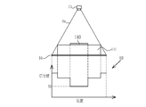
- 14 and 15 are diagrams for explaining the measurement of the scattered radiation transmittance Ts according to the body thickness of the subject Obj.
- a phantom 141 imitating a human body is placed on the surface of the radiography panel 14, and then a lead plate 140 is placed on the phantom 141.
- the phantom 141 is made of a material such as acrylic having various thicknesses such as 5 cm, 10 cm, and 20 cm, and having a radiation transmittance similar to that of water, for example.
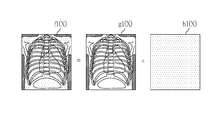
- the characteristic acquisition unit 104 acquires the radiation image K0 for measurement.
- the signal value of the radiation image K0 is large in the region where the radiation is directly irradiated on the radiography panel 14, and the signal value is small in the order of the region of the phantom 141 and the region of the lead plate 141.
- the signal value should be 0 in the region of the lead plate 140 in the radiation image K0.
- the radiation scattered by the phantom 141 reaches the region corresponding to the lead plate 140 mounted on the radiography panel 14. Therefore, the region of the lead plate 140 in the radiation image K0 has a signal value S0 corresponding to the scattered radiation component by the phantom 141.
- the phantom 141 is placed on the top plate 19, and the lead plate 140 is further placed on the phantom 141.
- the radiation source 13 is driven to irradiate the radiation imaging panel 14 with the radiation imaging panel 14 and the grid 110 arranged below the top plate 19.
- the characteristic acquisition unit 104 acquires the radiation image K1 for measurement. Similar to the radiation image K0, the signal value of the radiation image K1 has a large value in the region where the radiation is directly irradiated on the radiography panel 14, and the signal value decreases in the order of the region of the phantom 141 and the region of the lead plate 140.
- the lead placed on the radiography panel 14 was taken. Not only the radiation scattered by the phantom 141 but also the radiation scattered by the top plate 19 and the grid 110 reach the region corresponding to the plate 140. Therefore, the region of the lead plate 140 in the radiation image K1 has a signal value S1 corresponding to the scattered ray component by the phantom 141, the top plate 19, and the grid 110.
- the signal value S1 includes the scattered ray component due to the top plate 19 and the grid 110, the signal value S1 is larger than the signal value S0 shown in FIG. Therefore, when the phantom 141 having a thickness of t is photographed, the elements intervening between the subject Obj and the radiography panel 14, that is, the scattered radiation transmittance Ts of the top plate 19 and the grid 110 are calculated by S1 / S0. can do.
- the characteristic acquisition unit 104 calculates the scattered radiation transmittance Ts corresponding to each thickness as shown in FIGS. 14 and 15 by using at least two types of phantoms having different thicknesses. .. Further, the characteristic acquisition unit 104 derives the scattered radiation transmittance Ts having a thickness not found in the phantom 141 by interpolating the scattered radiation transmittance Ts for a plurality of measured thicknesses. As a result, the characteristic acquisition unit 104 interpolates the scattered radiation transmittance for the thickness between the thicknesses, so that the body thickness distribution t of the subject Obj and the subject Obj and the subject Obj are as shown in FIG. A table LUT1 showing the relationship between the scattered radiation transmittance Ts of the elements interposed between the radiography panels 14 is generated.
- 17 and 18 are diagrams for explaining the measurement of the primary line transmittance Tp according to the body thickness of the subject Obj.
- a phantom 141 imitating a human body is placed on the surface of the radiography panel 14.
- the phantom 141 the same one as in the case where the scattered radiation transmittance Ts is derived is used.
- the characteristic acquisition unit 104 acquires the radiation image K2 for measurement.
- the signal value S2 in the region corresponding to the phantom 141 in the radiation image K2 includes both the primary ray component and the scattered ray component of the radiation transmitted through the phantom 141.
- the scattered radiation component of the radiation transmitted through the phantom 141 is the signal value S0 in the radiation image K0 obtained by the method shown in FIG. Therefore, the primary line component of the radiation transmitted through the phantom 141 is derived by S2-S0.
- the characteristic acquisition unit 104 acquires the radiation image K3 for measurement.
- the signal value S3 in the region corresponding to the phantom 141 of the radiation image K3 includes both the primary line component and the radiation component of the radiation transmitted through the phantom 141 and the top plate 19 and the grid 110.
- the scattered radiation component of the radiation transmitted through the phantom 141, the top plate 19 and the grid 110 is the signal value S1 in the radiation image K1 obtained by the method shown in FIG. Therefore, the primary line component of the radiation transmitted through the phantom 141, the top plate 19 and the grid 110 is derived by S3-S1.
- the primary line transmittance Tp of the top plate 19 and the grid 110 interposed between the subject Obj and the radiography panel 14 when the phantom 141 is photographed is calculated by (S3-S1) / (S2-S0). can do.
- the characteristic acquisition unit 104 uses at least two types of phantoms having different thicknesses to obtain the primary line transmittance Tp corresponding to each thickness as shown in FIGS. 17 and 18. calculate. Further, the characteristic acquisition unit 104 derives the primary line transmittance Tp having a thickness not found in the phantom 141 by interpolating the primary line transmittance Tp for the plurality of measured thicknesses. As a result, as shown in FIG. 19, the characteristic acquisition unit 104 establishes a relationship between the body thickness distribution t of the subject Obj and the primary line transmittance Tp of the element interposed between the subject Obj and the radiography panel 14.
- the table LUT2 shown is generated.
- the tables LUT1 (first table) and LUT2 (second table) generated as described above are stored in the storage 34. It is assumed that the table is generated according to various imaging conditions (that is, radiation quality, dose, and radiation source distance), and also according to the type of grid 110 to be used, and stored in the storage 34.
- the characteristic acquisition unit 104 refers to the tables LUT1 and LUT2 stored in the storage 34 according to the imaging conditions acquired by the imaging condition acquisition unit 102, and refers to the elements intervening between the subject Obj and the radiation imaging panel 14.
- the primary ray transmittance Tp (t0) and the scattered radiation transmittance Ts (t0) corresponding to the initial body thickness distribution t0 are acquired. Since the primary line transmittance Tp and the scattered line transmittance Ts also depend on the radiation quality, the primary line transmittance Tp and the scattered line transmittance Ts are Tp (kV (, mmAI), t0) and Ts (kV (kV (), respectively. , MmAI), t0).
- the line distribution derivation unit 105 uses the imaging conditions, the body thickness distribution, and the radiation characteristics of the elements intervening between the subject Obj and the radiography unit 14, to obtain the primary line distribution of radiation detected by the radiography unit 14 and the radiation characteristics. Derivation of scattered radiation distribution.
- the primary radiation distribution Ip0 and the scattered radiation distribution Is0 after passing through the subject Obj are represented by the following equations (X4) and (X5), where t is the body thickness distribution.
- the PSF in the formula (X5) is a point spread function that represents the distribution of scattered rays spreading from one pixel, and is defined according to the radiation quality and body thickness.
- * indicates a convolution operation.
- the primary line distribution Ip0 and the scattered line distribution Is0 are derived for each pixel of the radiation image G0, but (x, y) are omitted in the equations (X4) and (X5). Further, in the second embodiment, the body thickness distribution, the primary line distribution Ip0, and the scattered line distribution Is0 are repeatedly derived as described later, but the first derivation of the primary line distribution Ip0 and the scattered line distribution Is0 is performed. In this case, the initial body thickness distribution t0 is used as the body thickness distribution t.
- Ip0 I0 ⁇ exp ⁇ - ⁇ (t) ⁇ t ⁇ (X4)
- Is0 Ip0 ⁇ STPR (kV (, mmAl), t) * PSF (kV (, mmAl), t) (X5)
- the line distribution deriving unit 105 uses the following equations (X6) and (X7) using the primary line transmittance Tp and the scattered radiation transmittance Ts of the elements interposed between the subject Obj and the radiography panel 14.
- the primary line distribution Ip1 and the scattered line distribution Is1 reaching the radiography panel 14 are derived.
- the primary line distribution Ip1 and the scattered line distribution Is1 reaching the radiography panel 14 are derived by the following equations (X6) and (X7).
- the sum Iw1 of the primary line distribution Ip1 and the scattered line distribution Is1 is derived by the following equation (X8).
- the initial body thickness distribution t0 is used as the body thickness distribution t when the first primary line distribution Ip1 and the scattered ray component Is1 are derived.
- Ip1 Ip0 ⁇ Tp (kV (, mmAl), t)
- Is1 Is0 ⁇ Ts (kV (, mmAl), t)
- Iw1 Ip1 + Is1 (X8)
- the second image generation unit 106 derives an error E1 between the sum of Is1 of the primary line distribution Ip1 and the scattered line distribution Is1 and the dose at each pixel position of the radiation image G0, that is, the pixel value I1.
- the error E2 is derived by the following equation (X9) or equation (X9-1).
- N represents the number of pixels of the radiation image G0
- ⁇ represents the sum of all the pixels of the radiation image G0. Since the equation (X9-1) calculates I1 / Iw1 in the log, the error E2 can be derived without depending on the dose applied to the subject Obj, that is, the reached dose I0.
- E2 (1 / N) ⁇ ⁇ ⁇ I1-Iw1 ⁇ 2 (X9)
- E2 (1 / N) ⁇ ⁇
- the second image generation unit 106 updates the body thickness distribution t so that the error E2 is minimized or the error E2 is less than the predetermined threshold value Th2. Then, the second image generation unit 106 repeats the acquisition of the primary line transmittance Tp and the scattered ray transmittance Ts based on the updated body thickness distribution, and the derivation of the primary line distribution Ip1 and the scattered ray distribution Is1.
- the operation performed by the second image generation unit 106 is referred to as a repetitive operation. Further, in the second embodiment, the second image generation unit 106 shall repeatedly perform the calculation so that the error E2 is less than the predetermined threshold value Th2.
- the second image generation unit 106 uses the processed radiation image whose pixel value is the primary line distribution Ipm derived based on the body thickness distribution tm of the subject Obj whose error E2 is less than the predetermined threshold value Th2. Output Gm.
- the radiation image G0 is stored in the storage 34 acquired by photographing.
- the radiation image acquisition unit 33 acquires the radiation image G0 from the storage 34 (step ST1).
- the shooting condition acquisition unit 102 acquires the shooting conditions when the subject Obj is shot (step ST2).
- the body thickness derivation unit 103 derives the initial body thickness distribution t0 based on the radiographic image G0 and the imaging conditions (step ST3).
- the characteristic acquisition unit 104 acquires the radiation characteristics of the element interposed between the subject Obj and the radiation imaging panel 14 at the time of photographing, that is, the primary ray transmittance Tp and the scattered radiation transmittance Ts (step ST4).
- the line distribution derivation unit 25 uses the imaging conditions, the body thickness distribution, and the radiation characteristics of the elements intervening between the subject Obj and the radiography panel 14, and the primary line of radiation detected by the radiography panel 14.
- the distribution Ip1 and the scattered radiation distribution Is1 are derived (step ST5). As described above, the processes of steps ST3 to ST5 are performed based on the initial body thickness distribution t0.
- the second image generation unit 106 repeatedly performs arithmetic processing (step ST6).
- the flow of the iterative calculation will be described with reference to the flowchart of FIG.
- the second image generation unit 106 derives an error E2 between the sum Iw1 of the primary line distribution Ip1 and the scattered line distribution Is1 and the pixel value I1 at each position of the radiation image G0 (step ST11).
- the second image generation unit 106 determines whether or not the error E2 is less than the pre-determined threshold value Th2 (step ST12).
- step ST12 is denied, the body thickness distribution t is updated so that the error E2 becomes small (step ST13).
- the characteristic acquisition unit 104 acquires new radiation characteristics, that is, primary ray transmittance Tp and scattered ray transmittance Tp, based on the updated body thickness distribution t (step ST14). Further, the line distribution derivation 105 derives a new primary line distribution Ip1 and a scattered line distribution Is1 (step ST15). Then, the second image generation unit 106 returns to the process of step ST11 and repeats the processes of steps ST11 to ST15. When step ST12 is affirmed, the iterative calculation process ends.
- the second image generation unit 106 derives a primary line distribution based on the body thickness distribution tm of the subject Obj in which the error E2 is less than the predetermined threshold value Th2.
- the processed radiation image Gm having Ipm as the pixel value is output (step ST7).
- the output processed radiation image Gm is displayed on the display 31 (step ST8).
- the body thickness distribution of the subject Obj is derived based on the radiation image G0 and the imaging conditions, and the radiation imaging panel 14 uses the imaging conditions, the body thickness distribution t, and the radiation characteristics of the elements.
- the primary radiation distribution Ip1 and the scattered radiation distribution Is1 detected by the above are derived.
- an error E2 between the sum Iw1 of the primary line distribution Ip1 and the scattered ray distribution Is1 and the pixel value at each position of the radiation image G0 is derived, and the error E2 is set to be less than the predetermined threshold value Th2.
- the thickness distribution was updated, and the acquisition of radiation characteristics and the derivation of the primary line distribution and the scattered line distribution based on the updated body thickness distribution were repeated.
- the position j support distribution Ip1 and the scattered radiation distribution Is1 can be derived in consideration of the radiation characteristics of the element interposed between the subject Obj and the radiography panel 14. Since the primary line distribution Ip1 derived in this way takes into consideration the radiation characteristics of the elements intervening between the subject Obj and the radiography panel 14, the scattered radiation component is accurately removed. There is. Therefore, according to the second embodiment, it is possible to acquire a processed radiographic image in which the radiation component is accurately removed in consideration of the element intervening between the subject Obj and the radiography panel 14.
- the top plate 19 and the grid of the photographing table 18 are used as elements intervening between the subject Obj and the radiography panel 14, but as shown in FIG. 22, the top plate is used.
- An air layer 112 may intervene between 19 and the grid 110.
- the primary line distribution Ip1 and the scattered line distribution Is1 can be derived by including the air layer 112 as an element intervening between the subject Obj and the radiography panel 14. preferable.
- the primary ray distribution Ip1 and the scattered ray distribution Is1 of the air layer 112 with respect to the above equations (X6) and (X7), as shown in the following equations (X6-1) and (X7-1).
- the thickness tile of the air layer 112 is the distance between the lower surface of the top plate 19 and the surface of the grid 110 on the subject Obj side.
- Ip1 Ip0 ⁇ Tp (kV (, mmAl), t) * PS Fair (kV (, mmAl), tair) (X6-1)
- Is1 Is0 ⁇ Ts (kV (, mmAl), t) * PS Fair (kV (, mmAl), tair) (X7-1)
- the hardware structure of the processing unit that executes various processes such as 105 and the second image generation unit 106 is various processors as shown below.
- Various processors include CPU (Central Processing Unit), GPU (Graphical Processing Unit), FPGA (Field Programmable Gate Array), which are general-purpose processors that execute software (programs) and function as various processing units.
- PLD Programmable Logic Device
- a processing unit may be composed of one of these various processors, or a combination of two or more processors of the same type or different types (for example, a plurality of FPGAs, a combination of a CPU and an FPGA, or a CPU and a CPU. It may be composed of a combination of GPUs, etc.). Further, a plurality of processing units may be configured by one processor. As an example of configuring a plurality of processing units with one processor, first, as represented by a computer such as a client or a server, one processor is configured by a combination of one or more CPUs and software. There is a form in which this processor functions as a plurality of processing units.
- SoC System On Chip
- a processor that realizes the functions of the entire system including a plurality of processing units with one IC (Integrated Circuit) chip is used.
- the various processing units are configured by using one or more of the above-mentioned various processors as a hardware-like structure.
- the hardware structure of these various processors is, more specifically, an electric circuit in the form of a combination of circuit elements such as semiconductor elements.
- Radiation imaging system 13 Radiation source 14 Radiation imaging panel 15 1st radiation detector 16 2nd radiation detector 17 Radiation energy conversion filter 18 Imaging table 19 Top plate 20 Console 21 Display 22 Operation unit 30 Radiation image processing device 31 Display 32 Operation Part 33 Radiation image acquisition unit 34 Storage 35 Image processing unit 36 First estimation unit 37 Second estimation unit 38 First image generation unit 40 Calculation unit 51 First radiation image 91 Distribution 92 Distribution 100 Radiation image acquisition unit 102 Imaging condition acquisition unit 103 Body thickness derivation part 104 Characteristic acquisition part 105 Line distribution derivation part 106 Second image generation part 110 Grid 112 Air layer 140 Lead plate 141 Phantom
Landscapes
- Health & Medical Sciences (AREA)
- Life Sciences & Earth Sciences (AREA)
- Engineering & Computer Science (AREA)
- Medical Informatics (AREA)
- Heart & Thoracic Surgery (AREA)
- Molecular Biology (AREA)
- Biophysics (AREA)
- Nuclear Medicine, Radiotherapy & Molecular Imaging (AREA)
- Optics & Photonics (AREA)
- Pathology (AREA)
- Radiology & Medical Imaging (AREA)
- Biomedical Technology (AREA)
- Physics & Mathematics (AREA)
- High Energy & Nuclear Physics (AREA)
- Surgery (AREA)
- Animal Behavior & Ethology (AREA)
- General Health & Medical Sciences (AREA)
- Public Health (AREA)
- Veterinary Medicine (AREA)
- Computer Vision & Pattern Recognition (AREA)
- Dentistry (AREA)
- Oral & Maxillofacial Surgery (AREA)
- Toxicology (AREA)
- Apparatus For Radiation Diagnosis (AREA)
Priority Applications (2)
| Application Number | Priority Date | Filing Date | Title |
|---|---|---|---|
| JP2021522800A JP7284816B2 (ja) | 2019-05-27 | 2020-05-27 | 放射線画像処理装置及び放射線画像処理方法 |
| US17/534,825 US12279903B2 (en) | 2019-05-27 | 2021-11-24 | Radiation image processing device and radiation image processing method |
Applications Claiming Priority (4)
| Application Number | Priority Date | Filing Date | Title |
|---|---|---|---|
| JP2019-098660 | 2019-05-27 | ||
| JP2019098660 | 2019-05-27 | ||
| JP2020-091087 | 2020-05-26 | ||
| JP2020091087 | 2020-05-26 |
Related Child Applications (1)
| Application Number | Title | Priority Date | Filing Date |
|---|---|---|---|
| US17/534,825 Continuation US12279903B2 (en) | 2019-05-27 | 2021-11-24 | Radiation image processing device and radiation image processing method |
Publications (1)
| Publication Number | Publication Date |
|---|---|
| WO2020241664A1 true WO2020241664A1 (ja) | 2020-12-03 |
Family
ID=73553744
Family Applications (1)
| Application Number | Title | Priority Date | Filing Date |
|---|---|---|---|
| PCT/JP2020/020848 Ceased WO2020241664A1 (ja) | 2019-05-27 | 2020-05-27 | 放射線画像処理装置及び放射線画像処理方法 |
Country Status (3)
| Country | Link |
|---|---|
| US (1) | US12279903B2 (https=) |
| JP (1) | JP7284816B2 (https=) |
| WO (1) | WO2020241664A1 (https=) |
Cited By (1)
| Publication number | Priority date | Publication date | Assignee | Title |
|---|---|---|---|---|
| EP4062834A4 (en) * | 2019-11-20 | 2022-12-21 | FUJIFILM Corporation | RADIOGRAPHIC IMAGE PROCESSING DEVICE, METHOD AND PROGRAM |
Citations (4)
| Publication number | Priority date | Publication date | Assignee | Title |
|---|---|---|---|---|
| JP2015043959A (ja) * | 2013-07-31 | 2015-03-12 | 富士フイルム株式会社 | 放射線画像解析装置および方法並びにプログラム |
| JP2015051081A (ja) * | 2013-09-05 | 2015-03-19 | 株式会社東芝 | 医用画像処理装置、x線診断装置およびx線コンピュータ断層撮影装置 |
| JP2015126864A (ja) * | 2013-11-29 | 2015-07-09 | 富士フイルム株式会社 | 放射線画像解析装置および方法並びにプログラム |
| JP2017225525A (ja) * | 2016-06-21 | 2017-12-28 | 富士フイルム株式会社 | 放射線画像処理装置、方法およびプログラム |
Family Cites Families (5)
| Publication number | Priority date | Publication date | Assignee | Title |
|---|---|---|---|---|
| WO2011027390A1 (ja) * | 2009-09-02 | 2011-03-10 | 株式会社島津製作所 | 放射線撮影装置および画像の取得方法 |
| JP6006193B2 (ja) | 2013-03-28 | 2016-10-12 | 富士フイルム株式会社 | 放射線画像処理装置および方法並びにプログラム |
| JP6006454B2 (ja) | 2013-03-28 | 2016-10-12 | 富士フイルム株式会社 | 放射線画像処理装置および方法並びにプログラム |
| JP6145889B2 (ja) * | 2014-03-24 | 2017-06-14 | 富士フイルム株式会社 | 放射線画像処理装置および方法並びにプログラム |
| JP6582510B2 (ja) * | 2015-04-15 | 2019-10-02 | コニカミノルタ株式会社 | 放射線画像撮影システム |
-
2020
- 2020-05-27 WO PCT/JP2020/020848 patent/WO2020241664A1/ja not_active Ceased
- 2020-05-27 JP JP2021522800A patent/JP7284816B2/ja active Active
-
2021
- 2021-11-24 US US17/534,825 patent/US12279903B2/en active Active
Patent Citations (4)
| Publication number | Priority date | Publication date | Assignee | Title |
|---|---|---|---|---|
| JP2015043959A (ja) * | 2013-07-31 | 2015-03-12 | 富士フイルム株式会社 | 放射線画像解析装置および方法並びにプログラム |
| JP2015051081A (ja) * | 2013-09-05 | 2015-03-19 | 株式会社東芝 | 医用画像処理装置、x線診断装置およびx線コンピュータ断層撮影装置 |
| JP2015126864A (ja) * | 2013-11-29 | 2015-07-09 | 富士フイルム株式会社 | 放射線画像解析装置および方法並びにプログラム |
| JP2017225525A (ja) * | 2016-06-21 | 2017-12-28 | 富士フイルム株式会社 | 放射線画像処理装置、方法およびプログラム |
Cited By (2)
| Publication number | Priority date | Publication date | Assignee | Title |
|---|---|---|---|---|
| EP4062834A4 (en) * | 2019-11-20 | 2022-12-21 | FUJIFILM Corporation | RADIOGRAPHIC IMAGE PROCESSING DEVICE, METHOD AND PROGRAM |
| US11918402B2 (en) | 2019-11-20 | 2024-03-05 | Fujifilm Corporation | Radiation image processing device, radiation image processing method, and radiation image processing program |
Also Published As
| Publication number | Publication date |
|---|---|
| US12279903B2 (en) | 2025-04-22 |
| JP7284816B2 (ja) | 2023-05-31 |
| JPWO2020241664A1 (https=) | 2020-12-03 |
| US20220079543A1 (en) | 2022-03-17 |
Similar Documents
| Publication | Publication Date | Title |
|---|---|---|
| US10235766B2 (en) | Radiographic image analysis device and method, and storage medium having stored therein program | |
| JP6704374B2 (ja) | 体脂肪率測定装置、方法およびプログラム | |
| CN105433967B (zh) | 放射线图像分析装置及方法以及程序 | |
| JP6653629B2 (ja) | 放射線画像処理装置、方法およびプログラム | |
| JP7686430B2 (ja) | 推定装置、方法およびプログラム | |
| JP7662442B2 (ja) | 推定装置、方法およびプログラム | |
| JP6129125B2 (ja) | 放射線画像解析装置および方法並びにプログラム | |
| JP7436723B2 (ja) | 情報処理装置、情報処理方法、及び情報処理プログラム | |
| JP6301439B2 (ja) | 放射線画像解析装置および方法並びにプログラム | |
| US12611157B2 (en) | Radiation image processing device, radiation image processing method, and radiation image processing program | |
| JP7254963B2 (ja) | 放射線画像処理装置、方法およびプログラム | |
| JP7284816B2 (ja) | 放射線画像処理装置及び放射線画像処理方法 | |
| JP2024010966A (ja) | 放射線画像処理装置、その作動方法、及び放射線画像処理プログラム | |
| JP7690362B2 (ja) | 脂肪量導出装置、方法およびプログラム | |
| JP7583653B2 (ja) | 推定装置、方法およびプログラム | |
| JP2023125605A (ja) | 放射線画像解析装置、その作動方法、及び放射線画像解析プログラム | |
| JP2022158575A (ja) | 位置決め装置、方法およびプログラム、並びに放射線画像処理装置、方法およびプログラム | |
| US12533098B2 (en) | Radiation image processing device, radiation image processing method, and radiation image processing program | |
| US12478344B2 (en) | Radiation image processing apparatus, operation method of radiation image processing apparatus, and non-transitory computer readable medium | |
| JP2026059650A (ja) | 放射線画像処理装置、方法およびプログラム | |
| JP2023177980A (ja) | 放射線画像処理装置、方法およびプログラム |
Legal Events
| Date | Code | Title | Description |
|---|---|---|---|
| 121 | Ep: the epo has been informed by wipo that ep was designated in this application |
Ref document number: 20814604 Country of ref document: EP Kind code of ref document: A1 |
|
| ENP | Entry into the national phase |
Ref document number: 2021522800 Country of ref document: JP Kind code of ref document: A |
|
| NENP | Non-entry into the national phase |
Ref country code: DE |
|
| 122 | Ep: pct application non-entry in european phase |
Ref document number: 20814604 Country of ref document: EP Kind code of ref document: A1 |