WO2020241215A1 - 車載用バックアップ電源装置 - Google Patents
車載用バックアップ電源装置 Download PDFInfo
- Publication number
- WO2020241215A1 WO2020241215A1 PCT/JP2020/018761 JP2020018761W WO2020241215A1 WO 2020241215 A1 WO2020241215 A1 WO 2020241215A1 JP 2020018761 W JP2020018761 W JP 2020018761W WO 2020241215 A1 WO2020241215 A1 WO 2020241215A1
- Authority
- WO
- WIPO (PCT)
- Prior art keywords
- unit
- converters
- battery
- voltage
- conductive paths
- Prior art date
- Legal status (The legal status is an assumption and is not a legal conclusion. Google has not performed a legal analysis and makes no representation as to the accuracy of the status listed.)
- Ceased
Links
Images



Classifications
-
- B—PERFORMING OPERATIONS; TRANSPORTING
- B60—VEHICLES IN GENERAL
- B60L—PROPULSION OF ELECTRICALLY-PROPELLED VEHICLES; SUPPLYING ELECTRIC POWER FOR AUXILIARY EQUIPMENT OF ELECTRICALLY-PROPELLED VEHICLES; ELECTRODYNAMIC BRAKE SYSTEMS FOR VEHICLES IN GENERAL; MAGNETIC SUSPENSION OR LEVITATION FOR VEHICLES; MONITORING OPERATING VARIABLES OF ELECTRICALLY-PROPELLED VEHICLES; ELECTRIC SAFETY DEVICES FOR ELECTRICALLY-PROPELLED VEHICLES
- B60L58/00—Methods or circuit arrangements for monitoring or controlling batteries or fuel cells, specially adapted for electric vehicles
- B60L58/10—Methods or circuit arrangements for monitoring or controlling batteries or fuel cells, specially adapted for electric vehicles for monitoring or controlling batteries
- B60L58/18—Methods or circuit arrangements for monitoring or controlling batteries or fuel cells, specially adapted for electric vehicles for monitoring or controlling batteries of two or more battery modules
- B60L58/21—Methods or circuit arrangements for monitoring or controlling batteries or fuel cells, specially adapted for electric vehicles for monitoring or controlling batteries of two or more battery modules having the same nominal voltage
-
- H—ELECTRICITY
- H02—GENERATION; CONVERSION OR DISTRIBUTION OF ELECTRIC POWER
- H02M—APPARATUS FOR CONVERSION BETWEEN AC AND AC, BETWEEN AC AND DC, OR BETWEEN DC AND DC, AND FOR USE WITH MAINS OR SIMILAR POWER SUPPLY SYSTEMS; CONVERSION OF DC OR AC INPUT POWER INTO SURGE OUTPUT POWER; CONTROL OR REGULATION THEREOF
- H02M3/00—Conversion of DC power input into DC power output
-
- B—PERFORMING OPERATIONS; TRANSPORTING
- B60—VEHICLES IN GENERAL
- B60L—PROPULSION OF ELECTRICALLY-PROPELLED VEHICLES; SUPPLYING ELECTRIC POWER FOR AUXILIARY EQUIPMENT OF ELECTRICALLY-PROPELLED VEHICLES; ELECTRODYNAMIC BRAKE SYSTEMS FOR VEHICLES IN GENERAL; MAGNETIC SUSPENSION OR LEVITATION FOR VEHICLES; MONITORING OPERATING VARIABLES OF ELECTRICALLY-PROPELLED VEHICLES; ELECTRIC SAFETY DEVICES FOR ELECTRICALLY-PROPELLED VEHICLES
- B60L58/00—Methods or circuit arrangements for monitoring or controlling batteries or fuel cells, specially adapted for electric vehicles
- B60L58/10—Methods or circuit arrangements for monitoring or controlling batteries or fuel cells, specially adapted for electric vehicles for monitoring or controlling batteries
- B60L58/24—Methods or circuit arrangements for monitoring or controlling batteries or fuel cells, specially adapted for electric vehicles for monitoring or controlling batteries for controlling the temperature of batteries
- B60L58/25—Methods or circuit arrangements for monitoring or controlling batteries or fuel cells, specially adapted for electric vehicles for monitoring or controlling batteries for controlling the temperature of batteries by controlling the electric load
-
- B—PERFORMING OPERATIONS; TRANSPORTING
- B60—VEHICLES IN GENERAL
- B60R—VEHICLES, VEHICLE FITTINGS, OR VEHICLE PARTS, NOT OTHERWISE PROVIDED FOR
- B60R16/00—Electric or fluid circuits specially adapted for vehicles and not otherwise provided for; Arrangement of elements of electric or fluid circuits specially adapted for vehicles and not otherwise provided for
- B60R16/02—Electric or fluid circuits specially adapted for vehicles and not otherwise provided for; Arrangement of elements of electric or fluid circuits specially adapted for vehicles and not otherwise provided for electric constitutive elements
- B60R16/03—Electric or fluid circuits specially adapted for vehicles and not otherwise provided for; Arrangement of elements of electric or fluid circuits specially adapted for vehicles and not otherwise provided for electric constitutive elements for supply of electrical power to vehicle subsystems or for
- B60R16/033—Electric or fluid circuits specially adapted for vehicles and not otherwise provided for; Arrangement of elements of electric or fluid circuits specially adapted for vehicles and not otherwise provided for electric constitutive elements for supply of electrical power to vehicle subsystems or for characterised by the use of electrical cells or batteries
-
- H—ELECTRICITY
- H01—ELECTRIC ELEMENTS
- H01M—PROCESSES OR MEANS, e.g. BATTERIES, FOR THE DIRECT CONVERSION OF CHEMICAL ENERGY INTO ELECTRICAL ENERGY
- H01M10/00—Secondary cells; Manufacture thereof
- H01M10/42—Methods or arrangements for servicing or maintenance of secondary cells or secondary half-cells
- H01M10/425—Structural combination with electronic components, e.g. electronic circuits integrated to the outside of the casing
-
- H—ELECTRICITY
- H01—ELECTRIC ELEMENTS
- H01M—PROCESSES OR MEANS, e.g. BATTERIES, FOR THE DIRECT CONVERSION OF CHEMICAL ENERGY INTO ELECTRICAL ENERGY
- H01M10/00—Secondary cells; Manufacture thereof
- H01M10/42—Methods or arrangements for servicing or maintenance of secondary cells or secondary half-cells
- H01M10/44—Methods for charging or discharging
-
- H—ELECTRICITY
- H01—ELECTRIC ELEMENTS
- H01M—PROCESSES OR MEANS, e.g. BATTERIES, FOR THE DIRECT CONVERSION OF CHEMICAL ENERGY INTO ELECTRICAL ENERGY
- H01M10/00—Secondary cells; Manufacture thereof
- H01M10/60—Heating or cooling; Temperature control
- H01M10/61—Types of temperature control
- H01M10/615—Heating or keeping warm
-
- H—ELECTRICITY
- H01—ELECTRIC ELEMENTS
- H01M—PROCESSES OR MEANS, e.g. BATTERIES, FOR THE DIRECT CONVERSION OF CHEMICAL ENERGY INTO ELECTRICAL ENERGY
- H01M10/00—Secondary cells; Manufacture thereof
- H01M10/60—Heating or cooling; Temperature control
- H01M10/62—Heating or cooling; Temperature control specially adapted for specific applications
- H01M10/625—Vehicles
-
- H—ELECTRICITY
- H01—ELECTRIC ELEMENTS
- H01M—PROCESSES OR MEANS, e.g. BATTERIES, FOR THE DIRECT CONVERSION OF CHEMICAL ENERGY INTO ELECTRICAL ENERGY
- H01M10/00—Secondary cells; Manufacture thereof
- H01M10/60—Heating or cooling; Temperature control
- H01M10/63—Control systems
-
- H—ELECTRICITY
- H02—GENERATION; CONVERSION OR DISTRIBUTION OF ELECTRIC POWER
- H02J—ELECTRIC POWER NETWORKS; CIRCUIT ARRANGEMENTS OR SYSTEMS FOR SUPPLYING OR DISTRIBUTING ELECTRIC POWER; SYSTEMS FOR STORING ELECTRIC ENERGY
- H02J7/00—Circuit arrangements for charging or discharging batteries or for supplying loads from batteries
- H02J7/34—Parallel operation in networks using both storage and other DC sources, e.g. providing buffering
-
- H—ELECTRICITY
- H02—GENERATION; CONVERSION OR DISTRIBUTION OF ELECTRIC POWER
- H02J—ELECTRIC POWER NETWORKS; CIRCUIT ARRANGEMENTS OR SYSTEMS FOR SUPPLYING OR DISTRIBUTING ELECTRIC POWER; SYSTEMS FOR STORING ELECTRIC ENERGY
- H02J7/00—Circuit arrangements for charging or discharging batteries or for supplying loads from batteries
- H02J7/50—Circuit arrangements for charging or discharging batteries or for supplying loads from batteries acting upon multiple batteries simultaneously or sequentially
-
- H—ELECTRICITY
- H02—GENERATION; CONVERSION OR DISTRIBUTION OF ELECTRIC POWER
- H02J—ELECTRIC POWER NETWORKS; CIRCUIT ARRANGEMENTS OR SYSTEMS FOR SUPPLYING OR DISTRIBUTING ELECTRIC POWER; SYSTEMS FOR STORING ELECTRIC ENERGY
- H02J7/00—Circuit arrangements for charging or discharging batteries or for supplying loads from batteries
- H02J7/855—Circuit arrangements for charging or discharging batteries or for supplying loads from batteries with circuits adapted for supplying loads from the battery
-
- H—ELECTRICITY
- H02—GENERATION; CONVERSION OR DISTRIBUTION OF ELECTRIC POWER
- H02J—ELECTRIC POWER NETWORKS; CIRCUIT ARRANGEMENTS OR SYSTEMS FOR SUPPLYING OR DISTRIBUTING ELECTRIC POWER; SYSTEMS FOR STORING ELECTRIC ENERGY
- H02J9/00—Circuit arrangements for emergency or stand-by power supply, e.g. for emergency lighting
- H02J9/04—Circuit arrangements for emergency or stand-by power supply, e.g. for emergency lighting in which the distribution system is disconnected from the normal source and connected to a standby source
- H02J9/06—Circuit arrangements for emergency or stand-by power supply, e.g. for emergency lighting in which the distribution system is disconnected from the normal source and connected to a standby source with automatic change-over, e.g. UPS systems
-
- H—ELECTRICITY
- H02—GENERATION; CONVERSION OR DISTRIBUTION OF ELECTRIC POWER
- H02J—ELECTRIC POWER NETWORKS; CIRCUIT ARRANGEMENTS OR SYSTEMS FOR SUPPLYING OR DISTRIBUTING ELECTRIC POWER; SYSTEMS FOR STORING ELECTRIC ENERGY
- H02J9/00—Circuit arrangements for emergency or stand-by power supply, e.g. for emergency lighting
- H02J9/04—Circuit arrangements for emergency or stand-by power supply, e.g. for emergency lighting in which the distribution system is disconnected from the normal source and connected to a standby source
- H02J9/06—Circuit arrangements for emergency or stand-by power supply, e.g. for emergency lighting in which the distribution system is disconnected from the normal source and connected to a standby source with automatic change-over, e.g. UPS systems
- H02J9/061—Circuit arrangements for emergency or stand-by power supply, e.g. for emergency lighting in which the distribution system is disconnected from the normal source and connected to a standby source with automatic change-over, e.g. UPS systems for DC powered loads
-
- B—PERFORMING OPERATIONS; TRANSPORTING
- B60—VEHICLES IN GENERAL
- B60L—PROPULSION OF ELECTRICALLY-PROPELLED VEHICLES; SUPPLYING ELECTRIC POWER FOR AUXILIARY EQUIPMENT OF ELECTRICALLY-PROPELLED VEHICLES; ELECTRODYNAMIC BRAKE SYSTEMS FOR VEHICLES IN GENERAL; MAGNETIC SUSPENSION OR LEVITATION FOR VEHICLES; MONITORING OPERATING VARIABLES OF ELECTRICALLY-PROPELLED VEHICLES; ELECTRIC SAFETY DEVICES FOR ELECTRICALLY-PROPELLED VEHICLES
- B60L2240/00—Control parameters of input or output; Target parameters
- B60L2240/40—Drive Train control parameters
- B60L2240/54—Drive Train control parameters related to batteries
- B60L2240/545—Temperature
-
- B—PERFORMING OPERATIONS; TRANSPORTING
- B60—VEHICLES IN GENERAL
- B60L—PROPULSION OF ELECTRICALLY-PROPELLED VEHICLES; SUPPLYING ELECTRIC POWER FOR AUXILIARY EQUIPMENT OF ELECTRICALLY-PROPELLED VEHICLES; ELECTRODYNAMIC BRAKE SYSTEMS FOR VEHICLES IN GENERAL; MAGNETIC SUSPENSION OR LEVITATION FOR VEHICLES; MONITORING OPERATING VARIABLES OF ELECTRICALLY-PROPELLED VEHICLES; ELECTRIC SAFETY DEVICES FOR ELECTRICALLY-PROPELLED VEHICLES
- B60L50/00—Electric propulsion with power supplied within the vehicle
- B60L50/50—Electric propulsion with power supplied within the vehicle using propulsion power supplied by batteries or fuel cells
- B60L50/60—Electric propulsion with power supplied within the vehicle using propulsion power supplied by batteries or fuel cells using power supplied by batteries
-
- H—ELECTRICITY
- H01—ELECTRIC ELEMENTS
- H01M—PROCESSES OR MEANS, e.g. BATTERIES, FOR THE DIRECT CONVERSION OF CHEMICAL ENERGY INTO ELECTRICAL ENERGY
- H01M10/00—Secondary cells; Manufacture thereof
- H01M10/42—Methods or arrangements for servicing or maintenance of secondary cells or secondary half-cells
- H01M10/425—Structural combination with electronic components, e.g. electronic circuits integrated to the outside of the casing
- H01M2010/4271—Battery management systems including electronic circuits, e.g. control of current or voltage to keep battery in healthy state, cell balancing
-
- H—ELECTRICITY
- H01—ELECTRIC ELEMENTS
- H01M—PROCESSES OR MEANS, e.g. BATTERIES, FOR THE DIRECT CONVERSION OF CHEMICAL ENERGY INTO ELECTRICAL ENERGY
- H01M2220/00—Batteries for particular applications
- H01M2220/20—Batteries in motive systems, e.g. vehicle, ship, plane
-
- H—ELECTRICITY
- H02—GENERATION; CONVERSION OR DISTRIBUTION OF ELECTRIC POWER
- H02J—ELECTRIC POWER NETWORKS; CIRCUIT ARRANGEMENTS OR SYSTEMS FOR SUPPLYING OR DISTRIBUTING ELECTRIC POWER; SYSTEMS FOR STORING ELECTRIC ENERGY
- H02J2105/00—Networks for supplying or distributing electric power characterised by their spatial reach or by the load
- H02J2105/30—Networks for supplying or distributing electric power characterised by their spatial reach or by the load the load networks being external to vehicles, i.e. exchanging power with vehicles
- H02J2105/33—Networks for supplying or distributing electric power characterised by their spatial reach or by the load the load networks being external to vehicles, i.e. exchanging power with vehicles exchanging power with road vehicles
- H02J2105/37—Networks for supplying or distributing electric power characterised by their spatial reach or by the load the load networks being external to vehicles, i.e. exchanging power with vehicles exchanging power with road vehicles exchanging power with electric vehicles [EV] or with hybrid electric vehicles [HEV]
-
- H—ELECTRICITY
- H02—GENERATION; CONVERSION OR DISTRIBUTION OF ELECTRIC POWER
- H02J—ELECTRIC POWER NETWORKS; CIRCUIT ARRANGEMENTS OR SYSTEMS FOR SUPPLYING OR DISTRIBUTING ELECTRIC POWER; SYSTEMS FOR STORING ELECTRIC ENERGY
- H02J2207/00—Details of circuit arrangements for charging or discharging batteries or supplying loads from batteries
- H02J2207/20—Charging or discharging characterised by the power electronics converter
-
- H—ELECTRICITY
- H02—GENERATION; CONVERSION OR DISTRIBUTION OF ELECTRIC POWER
- H02J—ELECTRIC POWER NETWORKS; CIRCUIT ARRANGEMENTS OR SYSTEMS FOR SUPPLYING OR DISTRIBUTING ELECTRIC POWER; SYSTEMS FOR STORING ELECTRIC ENERGY
- H02J7/00—Circuit arrangements for charging or discharging batteries or for supplying loads from batteries
- H02J7/90—Regulation of charging or discharging current or voltage
- H02J7/971—Regulation of charging or discharging current or voltage the charge cycle being controlled or terminated in response to non-electric parameters
- H02J7/975—Regulation of charging or discharging current or voltage the charge cycle being controlled or terminated in response to non-electric parameters in response to temperature
- H02J7/977—Regulation of charging or discharging current or voltage the charge cycle being controlled or terminated in response to non-electric parameters in response to temperature of the battery
Definitions
- This disclosure relates to an in-vehicle backup power supply device.
- Patent Document 1 discloses an example of a power supply device including this type of battery module.
- the charge capacity of the unit battery depends on the temperature, and as the temperature of the unit battery decreases, the internal resistance of the unit battery increases and the charge capacity decreases. That is, the chargeable area of the unit battery becomes narrower as its own temperature decreases. Due to these characteristics, the actual charge capacity of the unit battery tends to be small in an environment where the temperature of the unit battery tends to be low (for example, in a cold region or winter).
- the power supply device of Patent Document 1 raises the temperature of the charging module (battery unit) by performing constant voltage charging and constant current charging on the charging module (battery unit) by the electric power supplied from the external charger. And alleviate the problems caused by low temperature conditions.
- the power supply device of Patent Document 1 has a configuration in which an external charger must be indispensable in order to raise the temperature of the assembled battery.
- the present disclosure provides a technique capable of raising the temperature of the battery unit more efficiently with a simpler configuration.
- the in-vehicle backup power supply device of the present disclosure is A battery unit that consists of multiple unit batteries connected in series, A voltage converter equipped with a plurality of converters that boost or step down the input voltage and output it, A control unit that controls the voltage conversion unit and It is an in-vehicle backup power supply device that has A first circuit unit that constitutes a power path between the voltage conversion unit and the battery unit, A second circuit unit that constitutes a power path between the voltage conversion unit and the load, Have,
- the battery unit includes a plurality of conversion target units. Each of the conversion target units is composed of the unit battery or a plurality of the unit batteries connected in series.
- the first circuit section includes a plurality of first conductive paths that are conductive paths connecting each electrode having the highest potential in each of the conversion target sections and each of the converters, and each of the conversion target sections.
- a plurality of second conductive paths which are conductive paths for connecting each electrode having the lowest potential and each of the converters, are provided.
- the second circuit unit includes a plurality of third conductive paths, which are conductive paths arranged between each of the converters and the conductive paths on the load side.
- the control unit A plurality of discharge operations are performed in which the potential difference between the first conductive path and the second conductive path is used as an input voltage to boost or lower the voltage and apply an output voltage to the third conductive path according to the satisfaction of the first condition.
- any one or more of the converters are made to perform the discharge operation, and the voltage applied to the third conductive path is used as an input voltage for the other converters to boost or step down.
- a charging operation is performed in which an output voltage is applied between the first conductive path and the second conductive path.
- the temperature of the battery unit can be raised more efficiently with a simpler configuration.
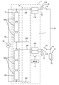
- FIG. 1 is a circuit diagram schematically showing an in-vehicle backup power supply device according to the first embodiment.
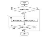
- FIG. 2 is a flowchart showing the operation of the in-vehicle backup power supply device of the first embodiment.
- FIG. 3 is a circuit diagram schematically showing the vehicle-mounted backup power supply device of the second embodiment.
- FIG. 4 is a flowchart showing the operation of the in-vehicle backup power supply device of the second embodiment.
- FIG. 5 is a circuit diagram schematically showing an in-vehicle backup power supply device according to the third embodiment.
- the in-vehicle backup power supply device of the present disclosure is (1)
- the in-vehicle backup power supply device of the present disclosure is It has a battery unit having a configuration in which a plurality of unit batteries are connected in series, a voltage conversion unit including a plurality of converters that step up or down the input voltage and output the voltage, and a control unit that controls the voltage conversion unit.
- This in-vehicle backup power supply device has a first circuit unit that constitutes a power path between the voltage conversion unit and the battery unit, and a second circuit unit that constitutes a power path between the voltage conversion unit and the load. ing.
- the battery unit includes a plurality of conversion target units. Each conversion target unit is composed of a unit battery or a plurality of unit batteries connected in series.
- the first circuit unit includes a plurality of first conductive paths and a plurality of second conductive paths.
- the plurality of first conductive paths are conductive paths that connect each electrode having the highest potential in each conversion target portion and each converter.
- the plurality of second conductive paths are conductive paths that connect each electrode having the lowest potential in each conversion target portion and each converter.
- the second circuit unit includes a plurality of third conductive paths, which are conductive paths arranged between the respective converters and the conductive paths on the load side.
- the control unit boosts or lowers the potential difference between the first conductive path and the second conductive path as an input voltage, and applies an output voltage to the third conductive path. Let each of them do it. Further, the control unit causes any one or more converters to perform a discharge operation according to the satisfaction of the second condition, and boosts or lowers the voltage applied to the third conductive path to the other converters as an input voltage. The charging operation is performed by applying an output voltage between the first conductive path and the second conductive path.
- the temperature of the battery unit can be raised by causing the battery unit to perform the discharge operation by one of the converters and the battery unit by the other converter. .. That is, this in-vehicle backup power supply device can raise the temperature of the battery unit more efficiently with a simpler configuration without providing a dedicated configuration for raising the temperature of the battery unit.
- the control unit of the in-vehicle backup power supply device of the present disclosure may cause at least one of a plurality of converters to perform an operation of alternately repeating a charging operation and a discharging operation according to the satisfaction of the second condition.
- the converter does not perform either charging or discharging, so it is possible to prevent the charging state of each unit battery from becoming overcharged or overdischarged, and the converter can be used. Either the charging operation or the discharging operation can be continuously performed. Therefore, this in-vehicle backup power supply device can satisfactorily raise the temperature of the battery unit.
- battery units are arranged such that at least one of a plurality of unit batteries or a plurality of conversion target units is arranged in a predetermined direction.
- the control unit is a unit battery located at both ends in a predetermined direction in the battery unit or at least one unit battery or a conversion target located in the central portion in a predetermined direction rather than the output power during the discharge operation of the converter corresponding to the conversion target unit. Suppression control that suppresses the output power during the discharge operation of the converter corresponding to the unit can be performed. With such a configuration, it is possible to suppress the temperature of the central portion of the battery portion from rising too much, and it is possible to suppress the occurrence of a temperature difference between both sides of the battery portion and the central portion. ..
- the vehicle-mounted backup power supply device of the present disclosure can perform suppression control when the temperature of at least the central portion of the control unit is higher than the temperature of the outer portion of the central portion. With such a configuration, the suppression control can be performed only when there is a temperature difference between the outer side and the central part of the battery part.
- the vehicle-mounted backup power supply device 1 (hereinafter, also referred to as power supply device 1) of the first embodiment has a battery unit 10, a voltage conversion unit 11, and a control unit 12.
- the battery unit 10 for example, a lithium ion battery composed of a plurality of unit batteries 10A (cells) or the like is used.
- the battery unit 10 is used as a power source that outputs power for driving an electric drive device (motor or the like) in a vehicle such as a hybrid vehicle or an electric vehicle (EV (Electric Vehicle)), for example.
- EV Electric Vehicle
- the battery unit 10 is configured as one conversion target unit 10B configured as a module in which a plurality of unit batteries 10A configured as a lithium ion battery are connected in series, and a plurality of conversion target units 10B are directly connected. It is configured to be able to output a desired output voltage in a connected form.
- a plurality of unit batteries 10A and a plurality of conversion target units 10B are arranged side by side in a predetermined direction (vertical direction in FIG. 1).
- a power generation device 50 mounted on the vehicle is electrically connected to the electrodes at both ends of the battery unit 10, and the battery unit 10 can be charged by the power generation device 50.
- the power generation device 50 is configured as a known in-vehicle generator, and is configured to be able to generate power by rotating a rotating shaft of an engine (not shown). When the power generation device 50 operates, the power generated by the power generation of the power generation device 50 is supplied to the battery unit 10 as DC power after rectification.
- the battery unit 10 is provided with a temperature detection unit 12A.
- the temperature detection unit 12A is composed of, for example, a known temperature sensor, and is arranged in a form of being in contact with or not in contact with the surface portion of the battery unit 10 or the like.
- the temperature detection unit 12A is configured to output a voltage value indicating the temperature at the arrangement position (that is, the surface temperature of the battery unit 10 or the temperature near the surface) and input it to the control unit 12.
- the voltage conversion unit 11 has a plurality of converters 11A and 11B.
- Each of the converters 11A and 11B is configured as a known bidirectional buck-boost DCDC converter including, for example, a semiconductor switching element and an inductor, and outputs the input voltage by stepping up or stepping down.
- the converters 11A and 11B are electrically connected to each conversion target unit 10B via the first circuit unit 30.
- the first circuit unit 30 constitutes a power path between the voltage conversion unit 11 and the battery unit.
- the first circuit unit 30 includes first conductive paths 30A and 30C and second conductive paths 30B and 30D.
- the converter 11A is electrically connected to the electrode on the highest potential side of the conversion target portion 10B via the first conductive path 30A.
- the converter 11A is electrically connected to the electrode on the lowest potential side of the conversion target portion 10B via the second conductive path 30B.
- the potential difference between the first conductive path 30A and the second conductive path 30B is input to the converter 11A as an input voltage.
- the converter 11B is electrically connected to the electrode on the highest potential side of the conversion target portion 10B via the first conductive path 30C.
- the converter 11B is electrically connected to the electrode on the lowest potential side of the conversion target portion 10B via the second conductive path 30D.
- the potential difference between the first conductive path 30C and the second conductive path 30D is input to the converter 11B as an input voltage.
- the converters 11A and 11B electrically connect to the switch element 52 that switches between conduction and non-conduction with the load-side conductive path 53 that supplies power to the load 51 via the third conductive path 31A and 31B of the second circuit unit 31. It is connected.
- the third conductive path 31A is arranged between the converter 11A and the load-side conductive path 53 on the load 51 side, and the third conductive path 31B is arranged between the converter 11B and the load-side conductive path 53 on the load 51 side. ..
- the second circuit unit 31 constitutes a power path between the voltage conversion unit 11 and the load 51.
- the switch element 52 is composed of, for example, a MOSFET (Metal Oxide Semiconductor Field Effect Transistor) or the like. Each switch element 52 is electrically connected to the load 51 via a load-side conductive path 53.
- the converters 11A and 11B are stepped up or down by the control unit 12 using the potential difference between the first conductive paths 30A and 30C and the second conductive paths 30B and 30D as an input voltage according to the satisfaction of the first condition.
- a discharge operation in which an output voltage is applied to the conductive paths 31A and 31B can be executed.
- the establishment of the first condition means, for example, that the ignition switch (not shown) provided in the vehicle is switched from the off state to the on state.
- Each of the converters 11A and 11B causes the control unit 12 to perform a discharge operation on any of the converters 11A and 11B according to the satisfaction of the second condition, and causes the other converters 11A and 11B to perform a discharge operation on the third conductive paths 31A and 31B.
- a charging operation (hereinafter, also referred to as a temperature raising operation) in which an output voltage is applied between the first conductive paths 30A and 30C and the second conductive paths 30B and 30D by boosting or stepping down the voltage applied to the input voltage. Can be done.
- the other converters 11A and 11B execute the charging operation based on the output voltage output to the third conductive paths 31A and 31B by the discharging operation of any of the converters 11A and 11B, and the first A predetermined potential difference is generated between the conductive paths 30A and 30C and the second conductive paths 30B and 30D, and the voltage is output as an output voltage.
- the establishment of the second condition means that, for example, the voltage value indicating the temperature of the battery unit 10 output from the temperature detection unit 12A (hereinafter, also referred to as the voltage value from the temperature detection unit 12A) is equal to or less than a predetermined threshold value (that is, a predetermined value). It is to be in a state of (below the temperature).
- the control unit 12 is mainly composed of, for example, a microcomputer, an arithmetic unit such as a CPU (Central Processing Unit), a memory such as a ROM (Read Only Memory) or a RAM (Random Access Memory), and an A / D converter. And so on.
- the control unit 12 is configured to be able to grasp the temperature of the battery unit 10 based on a signal from the temperature detection unit 12A that detects the surface temperature of the battery unit 10 or the temperature near the surface.
- the control unit 12 is configured to control the operation of the voltage conversion unit 11 based on the voltage value from the temperature detection unit 12A. Specifically, when the first condition is satisfied, the control unit 12 executes a control for causing the voltage conversion unit 11 to perform a discharge operation. When the second condition is satisfied, the control unit 12 executes a control for causing the voltage conversion unit 11 to perform a temperature raising operation.
- the user of the vehicle equipped with the power supply device 1 causes the vehicle to start a preliminary operation by using, for example, a remote controller or the like that can instruct the vehicle to perform a predetermined operation.
- the preparatory operation is, for example, an operation performed when the ignition switch is in the off state, and is an operation performed in a situation where the ignition switch is soon turned on.
- the preliminary operation ends when a predetermined condition is satisfied. Satisfying the predetermined condition means that, for example, the voltage value from the temperature detection unit 12A becomes larger than the threshold value.
- the control unit 12 determines the temperature of the battery unit 10 as shown in FIG. First, the control unit 12 determines whether or not the second condition is satisfied (step S1).
- control unit 12 determines whether or not the voltage value from the temperature detection unit 12A is equal to or less than the threshold value.
- the threshold value is stored in, for example, the ROM of the control unit 12. Further, when the control unit 12 determines that the voltage value from the temperature detection unit 12A is larger than the threshold value (No in step S1), the process ends and the control of the flowchart of FIG. 2 is repeated.
- step S1 the control unit 12 determines that the voltage value from the temperature detection unit 12A is equal to or less than the threshold value (Yes in step S1) (that is, the second condition is satisfied)
- the control unit 12 proceeds to step S2 and the voltage conversion unit 11
- the temperature raising operation is performed.
- the temperature of the conversion target unit 10B to which any one of the converters 11A and 11B that performs the discharge operation is connected rises by discharging.
- the temperature of the conversion target unit 10B to which any one of the converters 11A and 11B that performs the charging operation rises by being charged.
- the third conductive paths 31A and 31B are electrically connected to the load-side conductive paths 53 via the switch elements 52.
- the third conductive paths 31A and 31B of the converters 11A and 11B are electrically connected, and electric power can be exchanged between the converters 11A and 11B.
- a switch (not shown) is provided between the point Pa of the load-side conductive path 53 and the load 51 so that power is not supplied to the load 51 when the switch is opened in the temperature raising operation. It is configured in.
- step S3 it is determined whether or not the second condition is satisfied.
- the control unit 12 determines whether or not the voltage value from the temperature detection unit 12A is equal to or less than the threshold value.
- the control unit 12 proceeds to step S2.
- the control unit 12 ends the process, ends the temperature raising operation, and repeats the control of the flowchart of FIG.
- the control unit 12 causes at least one of the plurality of converters 11A and 11B to perform an operation of alternately repeating a charging operation and a discharging operation.
- each of the two converters 11A and 11B complementarily repeats the charging operation and the discharging operation.
- the converter 11B performs a charging operation while the converter 11A is discharging, and the converter 11A alternately repeats charging while the converter 11B is performing a discharging operation.
- each switch element 52 is closed, and the third conductive paths 31A and 31B are electrically connected via the load-side conductive path 53.
- a switch (not shown) between the point Pa of the load-side conductive path 53 and the load 51 is opened so that power is not supplied to the load 51.
- the converter 11A boosts or lowers the potential difference between the first conductive path 30A and the second conductive path 30B as an input voltage, and executes a discharge operation of applying an output voltage to the third conductive path 31A. To do.
- the converter 11B creates a predetermined potential difference between the first conductive path 30C and the second conductive path 30D and outputs it as an output voltage to be converted. Charge 10B.
- the converter 11B executes a discharge operation of boosting or stepping down the potential difference between the first conductive path 30C and the second conductive path 30D as an input voltage and applying an output voltage to the third conductive path 31B. To do. Then, based on the output voltage of the third conductive path 31A at this time, the converter 11A creates a predetermined potential difference between the first conductive path 30A and the second conductive path 30B and outputs it as an output voltage to be converted. Charge 10B. The first period and the second period are prevented from overlapping each other.
- the temperature raising operation can be continued without causing the battery unit 10 to be overcharged or overdischarged. ..
- the control unit 12 periodically compares the magnitude of the voltage value indicating the temperature of the battery unit 10 with the threshold value by repeatedly executing the flowchart shown in FIG. Then, when the control unit 12 determines that the voltage value indicating the temperature of the battery unit 10 is larger than the threshold value (that is, the second condition is not satisfied), the control unit 12 ends the temperature raising operation in the voltage conversion unit 11. At this time, since the predetermined condition is satisfied, the preliminary operation ends.
- each of the converters 11A and 11B is boosted or stepped down by the control unit 12 using the potential difference between the first conductive paths 30A and 30C and the second conductive paths 30B and 30D as an input voltage to output an output voltage to the third conductive paths 31A and 31B.
- the vehicle-mounted backup power supply device 1 of the present disclosure is Controls a battery unit 10 having a configuration in which a plurality of unit batteries 10A are connected in series, a voltage conversion unit 11 including a plurality of converters 11A and 11B for boosting or stepping down an input voltage and outputting the voltage conversion unit 11. It has a control unit 12 and the like.
- the in-vehicle backup power supply device 1 has a first circuit unit 30 that constitutes a power path between the voltage conversion unit 11 and the battery unit 10, and a second circuit that constitutes a power path between the voltage conversion unit 11 and the load 51. It has a part 31 and.
- the battery unit 10 includes a plurality of conversion target units 10B.
- Each conversion target unit 10B is composed of a unit battery 10A or a plurality of unit batteries 10A connected in series.
- the first circuit unit 30 includes a plurality of first conductive paths 30A and 30C and a plurality of second conductive paths 30B and 30D.
- the plurality of first conductive paths 30A and 30C are conductive paths that connect each electrode having the highest potential in each conversion target portion 10B and the respective converters 11A and 11B, respectively.
- the plurality of second conductive paths 30B and 30D are conductive paths that connect each electrode having the lowest potential in each conversion target portion 10B and each converter 11A, respectively.
- the second circuit unit 31 includes a plurality of third conductive paths 31A and 31B, which are conductive paths arranged between the respective converters 11A and the conductive paths on the load 51 side, respectively.
- the control unit 12 boosts or lowers the potential difference between the first conductive paths 30A and 30C and the second conductive paths 30B and 30D as an input voltage according to the satisfaction of the first condition to the third conductive paths 31A and 31B.
- the discharge operation of applying the output voltage is performed by each of the plurality of converters 11A and 11B. Further, the control unit 12 causes any of the converters 11A and 11B to perform a discharge operation according to the satisfaction of the second condition.
- the control unit 12 boosts or lowers the voltage applied to the third conductive paths 31A and 31B to the other converters 11A and 11B using the voltage applied to the third conductive paths 31A and 31B as an input voltage to boost or step down the first conductive paths 30A and 30C and the second conductive paths 30B.
- a charging operation is performed in which an output voltage is applied to and from 30D.
- the in-vehicle backup power supply device 1 causes the battery unit 10 to perform a discharge operation by any of the converters 11A and 11B.
- the vehicle-mounted backup power supply device 1 can raise the temperature of the battery unit 10 by causing the battery unit 10 to perform a charging operation by the other converters 11A and 11B. That is, the vehicle-mounted backup power supply device 1 can raise the temperature of the battery unit 10 more efficiently with a simpler configuration without providing a dedicated configuration for raising the temperature of the battery unit 10.
- the control unit 12 of the vehicle-mounted backup power supply device 1 of the present disclosure causes a plurality of converters 11A to perform an operation of alternately repeating a charging operation and a discharging operation in accordance with the satisfaction of the second condition.
- the converters 11A and 11B do not perform either a charging operation or a discharging operation. Therefore, it is possible to prevent the charging state of each unit battery 10A from becoming overcharged or overdischarged, and the converters 11A and 11B can continuously perform either the charging operation or the discharging operation. it can. Therefore, the vehicle-mounted backup power supply device 1 can satisfactorily raise the temperature of the battery unit 10.
- the vehicle-mounted backup power supply device 2 (hereinafter, also referred to as power supply device 2) according to the second embodiment will be described with reference to FIGS. 3 and 4.
- the power supply device 2 is different from the first embodiment in that converters 111A, 111B, 111C, 111D, 111E, 111F (hereinafter, also referred to as converters 111A to 111F) are provided corresponding to each unit battery 10A.
- converters 111A, 111B, 111C, 111D, 111E, 111F hereinafter, also referred to as converters 111A to 111F
- the same components are designated by the same reference numerals, and the description of the structure, action and effect will be omitted.
- the battery unit 110 of the power supply device 2 according to the second embodiment is formed by connecting a plurality of unit batteries 10A in series.
- a plurality of unit batteries 10A are arranged side by side in a predetermined direction.
- the battery unit 110 is provided with a plurality of temperature detection units 12A, 12B, 12C.
- the temperature detection unit 12A is arranged in a predetermined direction in which the unit batteries 10A are lined up, in a form of contacting or not in contact with the surface portion of the central portion 10D of the battery unit 110.
- the temperature detection unit 12B is arranged in a form of being in contact with or not in contact with the surface portion of one end 10C.
- the temperature detection unit 12C is arranged in a form of being in contact with or not in contact with the surface portion of the other end 10C.
- the voltage conversion unit 111 has each converter 111A to 111F.
- the converters 111A to 111F are provided corresponding to each unit battery 10A.
- the converters 111A to 111F are electrically connected to each unit battery 10A via the first circuit unit 130.
- the first circuit unit 130 includes the first conductive paths 130A, 130C, 130E, 130G, 130J, 130L (hereinafter, also referred to as the first conductive paths 130A to 130L) and the second conductive paths 130B, 130D, 130F, 130H, 130K, 130M. (Hereinafter, also referred to as a second conductive path 130B to 130M).
- Each of the first conductive paths 130A to 130L electrically connects the electrodes on the high potential side of each unit battery 10A and the converters 111A to 111F corresponding to each unit battery 10A.
- the second conductive paths 130B to 130M electrically connect the electrodes on the low potential side of each unit battery 10A and the converters 111A to 111F corresponding to each unit battery 10A.
- a second conductive path connected to a converter corresponding to the unit battery 10A on the high potential side is electrically connected to the electrode between the batteries of the two unit batteries 10A connected in series, and the unit battery on the low potential side is connected.
- the first conductive path connected to the converter corresponding to 10A is electrically connected.
- the second conductive path 130B connected to the converter 111A corresponding to the unit battery 10A on the high potential side is electrically connected, and the first conductive path connected to the converter 111B corresponding to the unit battery 10A on the low potential side.
- the 130C is electrically connected.
- the potential difference between the first conductive path and the second conductive path is input to each converter as an input voltage.
- the potential difference between the first conductive path 130A and the second conductive path 130B is input to the converter 111A as an input voltage.
- Each of the converters 111A to 111F conducts with the load 51 via the third conductive paths 131A, 131B, 131C, 131D, 131E, 131F (hereinafter, also referred to as the third conductive paths 131A to 131F) of the second circuit unit 131. It is electrically connected to the switch element 52 that switches non-conductivity.
- the control unit 12 determines the temperature of the battery unit 110 as shown in FIG.
- the control unit 12 determines whether or not the second condition is satisfied (step S11). Specifically, the control unit 12 has a voltage value (hereinafter, also referred to as a voltage value from each temperature detection unit 12A, 12B, 12C) indicating the temperature of the battery unit 110 input from the temperature detection units 12A, 12B, 12C. Determine if it is below the threshold.
- a voltage value hereinafter, also referred to as a voltage value from each temperature detection unit 12A, 12B, 12C
- step S11 the control unit 12 determines that the voltage values from at least one temperature detection unit 12A, 12B, 12C are equal to or less than the threshold value (Yes in step S11) (that is, the second condition is satisfied).
- the control unit 12 proceeds to step S12.
- the voltage conversion unit 111 is made to perform the temperature raising operation.
- the third conductive paths 131A to 131F are electrically connected to the load-side conductive paths 53 via the switch elements 52.
- the third conductive paths 131A to 131F of the converters 111A to 111F are electrically connected, and electric power can be exchanged between the converters 111A to 111F.
- a switch (not shown) is provided between the load-side conductive path 53 and the load 51 so that power is not supplied from the load-side conductive path 53 to the load 51 in the temperature raising operation.
- control unit 12 When the control unit 12 causes the voltage conversion unit 111 to perform a temperature raising operation, the control unit 12 causes a plurality of converters 111A to 111F to perform an operation of alternately repeating a charging operation and a discharging operation.
- each switch element 52 is closed, and the third conductive paths 131A to 131F are electrically connected via the load-side conductive path 53. Then, a switch (not shown) between the load-side conductive path 53 and the load 51 is opened, so that power is not supplied to the load 51. Then, during the first period, the converters 111A, 111B, 111C step up or down the potential difference between the first conductive paths 130A, 130C, 130E and the second conductive paths 130B, 130D, 130F as an input voltage to boost or lower the third conductive path. A discharge operation is performed in which an output voltage is applied to the paths 131A, 131B, and 131C.
- the converters 111D, 111E, 111F have the first conductive paths 130G, 130J, 130L and the second conductive paths 130H, 130K, 130M. A predetermined potential difference is generated between them and the output voltage is output. As a result, the unit battery 10A corresponding to the converters 111D, 111E, 111F is charged.
- the converters 111D, 111E, 111F step up or down the potential difference between the first conductive paths 130G, 130J, 130L and the second conductive paths 130H, 130K, 130M as an input voltage to boost or lower the third conductive path.
- a discharge operation is performed in which an output voltage is applied to the paths 131D, 131E, and 131F.
- the converters 111A, 111B, 111C have the first conductive paths 130A, 130C, 130E and the second conductive paths 130B, 130D, 130F.
- a predetermined potential difference is generated between them and the voltage is output as an output voltage.
- the unit battery 10A corresponding to the converters 111A, 111B, 111C is charged.
- the first period and the second period are prevented from overlapping each other.
- the charging operation and the discharging operation of the converters 111A, 111B, 111C and the converters 111D, 111E, 111F are alternately repeated, but the combination of the converters that alternately repeat the charging operation and the discharging operation is Not limited to this.
- the converters 111A and 111B, 111C, 111D, 111E, 111F may be combined, or the converters 111A, 111B and 111C, 111D, 111E, 111F may be combined.
- the control unit 12 has a configuration capable of comparing the magnitudes of the central voltage value and the voltage values at both ends.
- the central voltage value is a voltage value from a temperature detection unit 12A arranged in the central portion 10D of the battery unit 110 in a predetermined direction in which the unit batteries 10A are lined up when the voltage conversion unit 111 is subjected to a temperature raising operation. Is.
- the voltage values at both ends are voltage values from the temperature detection units 12B and 12C arranged at both ends 10C of the battery unit 110.
- the control unit 12 causes the voltage conversion unit 111 to perform a temperature raising operation, the magnitude of the central voltage value and the voltage values at both ends, and the magnitude of the voltage value at the central portion and the voltage values at both ends. Compare with the difference.
- a predetermined temperature condition in which the central voltage value is larger than the voltage values at both ends and the difference between these magnitudes is larger than the predetermined threshold value is satisfied (Yes in step S13)
- the control unit 12 proceeds to step S14. Suppression control is performed.
- the suppression control means that the converters 111A and 111F corresponding to the unit batteries 10A at both ends 10C and the third conductive paths 131B and 111B during the discharging operation of the converters 111B, 111C, 111D and 111E corresponding to the unit batteries 10A in the central portion 10D. This is a control that reduces the output power to 131C, 131D, and 131E.
- the control unit 12 suppresses control when the central voltage value does not become larger than the voltage values at both ends or the difference between these magnitudes becomes equal to or less than a predetermined threshold value (No in step S13) (that is, the predetermined temperature condition is not satisfied). Is stopped (step S15).
- the suppression control may be performed as follows depending on the difference in magnitude between the central voltage value and the voltage values at both ends. For example, when a predetermined temperature condition is satisfied and the difference between the central voltage value and the voltage values at both ends increases, the control unit 12 is the third in the discharging operation of the converters 111B to 111E corresponding to the unit battery 10A of the central portion 10D. The output power output to the conductive paths 131B to 131E may be reduced.
- the control unit 12 is the third in the discharging operation of the converters 111B to 111E corresponding to the unit battery 10A of the central portion 10D.
- the output power output to the conductive paths 131B to 131E may be increased.
- step S16 it is determined whether or not the second condition is satisfied. Specifically, when the control unit 12 determines that all the voltage values from the temperature detection units 12A, 12B, and 12C are larger than the threshold value (No in step S16) (that is, the second condition is not satisfied), the voltage conversion unit 12 The temperature raising operation in 111 is terminated. At this time, the preliminary operation ends. Further, in step S16, when it is determined that the voltage values from at least one temperature detection unit 12A, 12B, 12C are equal to or less than the threshold value (Yes in step S16) (that is, the second condition is satisfied), the process proceeds to step S12. To do.
- Each converter 111A to 111F boosts or lowers the potential difference between the first conductive paths 130A to 130L and the second conductive paths 130B to 130M as an input voltage by the control unit 12, and outputs an output voltage to the third conductive paths 131A to 131F.
- the battery unit 110 has a plurality of unit batteries 10A arranged side by side in a predetermined direction.
- the control unit 12 is the converters 111B to 111E corresponding to the unit battery 10A located in the central portion 10D in the predetermined direction rather than the converters 111A and 111F corresponding to the unit batteries 10A located at both ends 10C in the predetermined direction in the battery unit 110.
- the output voltage output to the third conductive paths 131B to 131E during the discharge operation is reduced. With such a configuration, it is possible to prevent the temperature of the central portion 10D of the battery portion 110 from rising too much, and a temperature difference occurs between both ends 10C of the battery portion 110 and the central portion 10D. Can be suppressed.
- control unit 12 performs suppression control when the temperature of the central portion 10D is higher than the temperature outside the central portion 10D. With this configuration, suppression control can be performed only when there is a temperature difference between both ends 10C of the battery unit 110 and the central portion 10D.
- the vehicle-mounted backup power supply device 3 (hereinafter, also referred to as power supply device 3) according to the third embodiment will be described with reference to FIG.
- the power supply device 3 is different from the first embodiment in that the temperature detection unit is not provided.
- the same components as those in the first embodiment are designated by the same reference numerals, and the description of the structure, action and effect will be omitted.
- the user of the vehicle equipped with the power supply device 3 uses, for example, a remote controller or the like that can instruct the vehicle to perform a predetermined operation, and causes the vehicle to start a preliminary operation.
- the control unit 12 causes the voltage conversion unit 11 to perform a temperature raising operation.
- the temperature of the conversion target unit 10B to which any one of the converters 11A and 11B that performs the discharge operation is connected rises by discharging.
- the temperature of the conversion target unit 10B to which any one of the converters 11A and 11B that performs the charging operation rises by being charged.
- the third conductive paths 31A and 31B are electrically connected to the load-side conductive paths 53 via the switch elements 52.
- the third conductive paths 31A and 31B of the converters 11A and 11B are electrically connected, and electric power can be exchanged between the converters 11A and 11B.
- a switch (not shown) is provided between the load-side conductive path 53 and the load 51, and is configured so that power is not supplied to the load 51 when the switch is opened in the temperature raising operation. ing.
- the control unit 12 determines whether or not a predetermined time has elapsed since the temperature raising operation was started. If it is determined that a predetermined time has not elapsed since the temperature raising operation was started, the temperature raising operation is continued. When it is determined that a predetermined time has elapsed since the temperature raising operation started, the temperature raising operation ends. At this time, since the predetermined condition is satisfied, the preliminary operation ends.
- the operation of the converters 11A and 11B of the voltage conversion unit 11 in the temperature raising operation of the third embodiment is the same as that of the first embodiment.
- the converters 11A and 11B alternately repeat the charging operation and the discharging operation by the control unit 12, so that the battery unit 10 continues the temperature raising operation without being overcharged or overdischarged. can do.
- each of the converters 11A and 11B is boosted or stepped down by the control unit 12 using the potential difference between the first conductive paths 30A and 30C and the second conductive paths 30B and 30D as an input voltage, and the output voltage is supplied to the third conductive paths 31A and 31B.
- the configuration of the converter 111A corresponding to the unit battery 10A is illustrated, but in the battery unit in which a plurality of change target units composed of a plurality of unit batteries are arranged in series, each conversion target unit is supported.
- the operation of the converter may be controlled as in the second embodiment.
- the output voltage of the converters 111B, 111C, 111D, 111E in the central portion 10D to the third conductive paths 131B, 131C, 131D, 131E is suppressed based on the voltage values from the plurality of temperature detection units 12A. It is supposed to be.
- the output voltage of the converter in the central portion to the third conductive path may be suppressed to be lower than the output voltage of the converter outside the central portion to the third conductive path.
- Third conductive path 50 Power generation device 51 ... Load 52 .
- Switch element 53 ... Load-side conductive path
Landscapes
- Engineering & Computer Science (AREA)
- Power Engineering (AREA)
- Chemical & Material Sciences (AREA)
- General Chemical & Material Sciences (AREA)
- Electrochemistry (AREA)
- Chemical Kinetics & Catalysis (AREA)
- Manufacturing & Machinery (AREA)
- Mechanical Engineering (AREA)
- Business, Economics & Management (AREA)
- Emergency Management (AREA)
- Sustainable Development (AREA)
- Transportation (AREA)
- Sustainable Energy (AREA)
- Life Sciences & Earth Sciences (AREA)
- Automation & Control Theory (AREA)
- Microelectronics & Electronic Packaging (AREA)
- Charge And Discharge Circuits For Batteries Or The Like (AREA)
- Secondary Cells (AREA)
- Electric Propulsion And Braking For Vehicles (AREA)
- Stand-By Power Supply Arrangements (AREA)
- Dc-Dc Converters (AREA)
Priority Applications (3)
| Application Number | Priority Date | Filing Date | Title |
|---|---|---|---|
| CN202080034283.5A CN113812056A (zh) | 2019-05-27 | 2020-05-11 | 车载用备用电源装置 |
| US17/612,309 US20220231533A1 (en) | 2019-05-27 | 2020-05-11 | In-vehicle backup power supply device |
| DE112020002644.2T DE112020002644T5 (de) | 2019-05-27 | 2020-05-11 | Bordeigene Reservestromversorgungseinrichtung |
Applications Claiming Priority (2)
| Application Number | Priority Date | Filing Date | Title |
|---|---|---|---|
| JP2019098238A JP2020195178A (ja) | 2019-05-27 | 2019-05-27 | 車載用バックアップ電源装置 |
| JP2019-098238 | 2019-05-27 |
Publications (1)
| Publication Number | Publication Date |
|---|---|
| WO2020241215A1 true WO2020241215A1 (ja) | 2020-12-03 |
Family
ID=73548122
Family Applications (1)
| Application Number | Title | Priority Date | Filing Date |
|---|---|---|---|
| PCT/JP2020/018761 Ceased WO2020241215A1 (ja) | 2019-05-27 | 2020-05-11 | 車載用バックアップ電源装置 |
Country Status (5)
| Country | Link |
|---|---|
| US (1) | US20220231533A1 (https=) |
| JP (1) | JP2020195178A (https=) |
| CN (1) | CN113812056A (https=) |
| DE (1) | DE112020002644T5 (https=) |
| WO (1) | WO2020241215A1 (https=) |
Families Citing this family (4)
| Publication number | Priority date | Publication date | Assignee | Title |
|---|---|---|---|---|
| WO2022014099A1 (ja) * | 2020-07-13 | 2022-01-20 | 株式会社オートネットワーク技術研究所 | 車両用のバックアップ装置 |
| CN113765177B (zh) * | 2021-07-30 | 2024-06-11 | 华为数字能源技术有限公司 | 一种电池模块和充电系统 |
| DE102023103128A1 (de) * | 2023-02-09 | 2024-08-14 | Bayerische Motoren Werke Aktiengesellschaft | Speichereinrichtung zum Speichern von elektrischer Energie für ein Kraftfahrzeug sowie Kraftfahrzeug |
| US12240347B2 (en) * | 2023-05-02 | 2025-03-04 | Toyota Motor North America, Inc. | Systems and methods for an integrated vehicle and structure charger |
Citations (2)
| Publication number | Priority date | Publication date | Assignee | Title |
|---|---|---|---|---|
| JP2009055687A (ja) * | 2007-08-24 | 2009-03-12 | Nippon Soken Inc | 車両用dcdcコンバータ装置 |
| WO2016111106A1 (ja) * | 2015-01-06 | 2016-07-14 | 三菱電機株式会社 | 電池システム |
Family Cites Families (8)
| Publication number | Priority date | Publication date | Assignee | Title |
|---|---|---|---|---|
| JP5502918B2 (ja) * | 2011-10-13 | 2014-05-28 | 株式会社日本自動車部品総合研究所 | 組電池の充放電装置 |
| JP2014054143A (ja) | 2012-09-10 | 2014-03-20 | Toshiba Corp | 電源装置、充電方法及びプログラム |
| US20160016483A1 (en) * | 2013-04-03 | 2016-01-21 | Autonetworks Technologies, Ltd. | Control apparatus, power supply control apparatus, charge control method, charge control apparatus, and power supply apparatus for vehicles |
| US9929449B2 (en) * | 2014-06-10 | 2018-03-27 | Vertiv Energy Systems, Inc. | Systems and methods for warming batteries |
| JP6196650B2 (ja) * | 2015-10-15 | 2017-09-13 | 三菱電機株式会社 | 電力供給システム |
| JP2018050381A (ja) * | 2016-09-21 | 2018-03-29 | 株式会社オートネットワーク技術研究所 | 車両用電源装置 |
| KR102695515B1 (ko) * | 2016-10-05 | 2024-08-14 | 삼성전자주식회사 | 배터리 온도 제어 방법, 배터리 관리 장치 및 시스템 |
| JP6705357B2 (ja) * | 2016-10-14 | 2020-06-03 | 株式会社オートネットワーク技術研究所 | 車載用のバックアップ装置 |
-
2019
- 2019-05-27 JP JP2019098238A patent/JP2020195178A/ja active Pending
-
2020
- 2020-05-11 DE DE112020002644.2T patent/DE112020002644T5/de not_active Withdrawn
- 2020-05-11 CN CN202080034283.5A patent/CN113812056A/zh active Pending
- 2020-05-11 US US17/612,309 patent/US20220231533A1/en not_active Abandoned
- 2020-05-11 WO PCT/JP2020/018761 patent/WO2020241215A1/ja not_active Ceased
Patent Citations (2)
| Publication number | Priority date | Publication date | Assignee | Title |
|---|---|---|---|---|
| JP2009055687A (ja) * | 2007-08-24 | 2009-03-12 | Nippon Soken Inc | 車両用dcdcコンバータ装置 |
| WO2016111106A1 (ja) * | 2015-01-06 | 2016-07-14 | 三菱電機株式会社 | 電池システム |
Also Published As
| Publication number | Publication date |
|---|---|
| JP2020195178A (ja) | 2020-12-03 |
| CN113812056A (zh) | 2021-12-17 |
| US20220231533A1 (en) | 2022-07-21 |
| DE112020002644T5 (de) | 2022-03-10 |
Similar Documents
| Publication | Publication Date | Title |
|---|---|---|
| CN109792160B (zh) | 车载用的备用装置 | |
| WO2020241215A1 (ja) | 車載用バックアップ電源装置 | |
| JP7094780B2 (ja) | Dc/dc変換ユニット | |
| JP2018191440A (ja) | 車両用電源制御装置、車両用電源装置、及び車両用電源制御装置の制御回路 | |
| JP2020010517A (ja) | 充電制御装置及び充電制御システム | |
| CN113316526A (zh) | 车辆用电源控制装置及车辆用电源装置 | |
| CN111277133A (zh) | 用于控制车辆的低压直流至直流转换器的装置和方法 | |
| JP6885302B2 (ja) | 車両用電源システム | |
| JP6428524B2 (ja) | 車両用電源システム | |
| JP2018011372A (ja) | 電源制御装置、及び電源システム | |
| JP2016181943A (ja) | 電源システム | |
| JP6610453B2 (ja) | 電源制御装置、及び電源システム | |
| WO2019244606A1 (ja) | 車両用電源装置 | |
| CN111746279A (zh) | 电源系统 | |
| CN113812055B (zh) | 车载用备用电源装置 | |
| JP2017112734A (ja) | バッテリ制御システム | |
| JP6034734B2 (ja) | 電力システム | |
| GB2565091A (en) | Multiple output battery system with alternator architectures | |
| JP2017147887A (ja) | 電源システム | |
| CN117199582A (zh) | 电源装置 | |
| JP2014054119A (ja) | 車載電力制御装置 | |
| JP2019134636A (ja) | 充電システム及び充電方法 | |
| JP2010268641A (ja) | 駆動装置 | |
| GB2565090A (en) | Multiple output battery system | |
| JP2016197958A (ja) | 電源システム |
Legal Events
| Date | Code | Title | Description |
|---|---|---|---|
| 121 | Ep: the epo has been informed by wipo that ep was designated in this application |
Ref document number: 20813601 Country of ref document: EP Kind code of ref document: A1 |
|
| 122 | Ep: pct application non-entry in european phase |
Ref document number: 20813601 Country of ref document: EP Kind code of ref document: A1 |