WO2020240966A1 - ベーンポンプ - Google Patents
ベーンポンプ Download PDFInfo
- Publication number
- WO2020240966A1 WO2020240966A1 PCT/JP2020/009113 JP2020009113W WO2020240966A1 WO 2020240966 A1 WO2020240966 A1 WO 2020240966A1 JP 2020009113 W JP2020009113 W JP 2020009113W WO 2020240966 A1 WO2020240966 A1 WO 2020240966A1
- Authority
- WO
- WIPO (PCT)
- Prior art keywords
- phase
- rotor
- vane
- pump
- peripheral surface
- Prior art date
- Legal status (The legal status is an assumption and is not a legal conclusion. Google has not performed a legal analysis and makes no representation as to the accuracy of the status listed.)
- Ceased
Links
Images




Classifications
-
- F—MECHANICAL ENGINEERING; LIGHTING; HEATING; WEAPONS; BLASTING
- F04—POSITIVE - DISPLACEMENT MACHINES FOR LIQUIDS; PUMPS FOR LIQUIDS OR ELASTIC FLUIDS
- F04C—ROTARY-PISTON, OR OSCILLATING-PISTON, POSITIVE-DISPLACEMENT MACHINES FOR LIQUIDS; ROTARY-PISTON, OR OSCILLATING-PISTON, POSITIVE-DISPLACEMENT PUMPS
- F04C18/00—Rotary-piston pumps specially adapted for elastic fluids
- F04C18/30—Rotary-piston pumps specially adapted for elastic fluids having the characteristics covered by two or more of groups F04C18/02, F04C18/08, F04C18/22, F04C18/24, F04C18/48, or having the characteristics covered by one of these groups together with some other type of movement between co-operating members
- F04C18/34—Rotary-piston pumps specially adapted for elastic fluids having the characteristics covered by two or more of groups F04C18/02, F04C18/08, F04C18/22, F04C18/24, F04C18/48, or having the characteristics covered by one of these groups together with some other type of movement between co-operating members having the movement defined in group F04C18/08 or F04C18/22 and relative reciprocation between the co-operating members
- F04C18/344—Rotary-piston pumps specially adapted for elastic fluids having the characteristics covered by two or more of groups F04C18/02, F04C18/08, F04C18/22, F04C18/24, F04C18/48, or having the characteristics covered by one of these groups together with some other type of movement between co-operating members having the movement defined in group F04C18/08 or F04C18/22 and relative reciprocation between the co-operating members with vanes reciprocating with respect to the inner member
Definitions
- This disclosure relates to vane pumps.
- a vane pump for making a negative pressure chamber of a brake booster in a vehicle such as an automobile.
- the vane pump includes a rotor having a slit formed on the outer peripheral surface and a vane arranged in the slit, and the vane slides on the cam surface while being pressed against the cam surface of the pump chamber by centrifugal force due to the rotation of the rotor. It is configured to do.
- Patent Document 1 does not disclose any measures for solving such a problem.
- At least one embodiment of the present disclosure aims to provide a vane pump capable of improving pump efficiency.
- the vane pump according to at least one embodiment of the present invention is The pump casing that forms the pump chamber and A rotor placed in the pump chamber and having multiple slits on the outer peripheral surface, With multiple vanes, each placed in multiple slits,
- the pump chamber includes an inner peripheral surface formed so that the distance from the center of rotation of the rotor changes in the circumferential direction of the rotor.
- the inner peripheral surface of the pump chamber is The most upstream position from the first angular position in the circumferential direction where the distance between the inner peripheral surface and the rotation center of the rotor is the minimum to the maximum angle position on the downstream side of the first angular position in the rotor rotation direction.
- the angle to the second angle position is ⁇ 1
- the angle from the first angle position to the third angle position located at the most upstream of the angle positions where the distance is the minimum on the downstream side of the second angle position in the rotation direction is ⁇ 2 .
- it is configured to satisfy ⁇ 1 ⁇ 2/2.
- the vane pump according to at least one embodiment of the present invention is The pump casing that forms the pump chamber and A rotor placed in the pump chamber and having multiple slits on the outer peripheral surface, With multiple vanes, each placed in multiple slits,
- the pump chamber includes an inner peripheral surface formed so that the distance from the center of rotation of the rotor changes in the circumferential direction of the rotor.
- the protrusion amount change curve showing the relationship between the phase of the rotor in the rotation direction of the rotor and the protrusion amount of the first vane among the plurality of vanes protruding from the outer peripheral surface of the rotor.
- the phase of the rotor that maximizes the protrusion of the first vane is the first phase
- the phase of the rotor that minimizes the protrusion of the first vane after the first phase is the second phase
- the phase of the rotor that minimizes the protrusion of the first vane is the second phase.
- the protrusion amount is Amax
- the protrusion amount of the first vane in the second phase is Amin
- the phase of the rotor whose protrusion amount is half of (Amax-Amin) between the first phase and the second phase is the third phase.
- the third phase is located between the first phase and the fourth phase.
- the phase of the rotor that maximizes the amount of protrusion of the first vane is the first phase
- the phase of the rotor that minimizes the amount of protrusion of the first vane next to the first phase is the second phase
- the phase of the first vane in the first phase The protrusion amount is Amax
- the protrusion amount of the first vane in the second phase is Amin
- the phase of the rotor whose protrusion amount is half of (Amax-Amin) between the first phase and the second phase is the third phase.
- the third phase may be located between the first phase and the fourth phase.
- the vane velocity change line showing the relationship between the rotor phase in the rotor rotation direction and the velocity of the first vane in the protruding direction of the first vane is the velocity between the first phase and the second phase as the phase advances. Including the first section where In the first section, the slope of the velocity may become smaller as the phase advances.
- the slope of the velocity may gradually decrease as the phase advances.
- the pressure in the first space defined by two adjacent vanes in the pump chamber may be increased to atmospheric pressure or higher, and then the first space and the exhaust port of the pump chamber may communicate with each other.
- the inner peripheral surface of the pump chamber is The distance between the inner peripheral surface and the rotation center of the rotor may be configured to have a maximum value at two angular positions symmetrical with respect to the rotation center.
- the inner peripheral surface of the pump chamber is The distance between the inner peripheral surface and the rotation center of the rotor may be configured to have a maximum value at three angular positions that are evenly spaced in the circumferential direction of the rotor.
- the phase of the rotor corresponding to the minimum value of the volume is set as the first. 5 phases, the phase closest to the 5th phase among the phases corresponding to the turning points of the volume change curve in the section where the volume decreases is the 6th phase, the angle from the 5th to the 6th phases is ⁇ 1, and the volume change curve When the angle corresponding to one cycle is ⁇ 2, ⁇ 1 / ⁇ 2 ⁇ 3/4 may be satisfied.
- FIG. 1 It is a schematic exploded perspective view which shows the vane pump 2 which concerns on one Embodiment. It is a partially cutaway sectional view of the vane pump 2 shown in FIG. It is a figure which looked at the pump cover 18 from above. It is a top view which shows the structural example of the pump chamber 5 in one Embodiment. It is a figure which illustrates the shape of the inner peripheral surface 42 in one Embodiment. It is a figure which illustrates the volume change of the 1st space S1 in the vane pump 2 which concerns on one Embodiment. It is the schematic which shows the structural example of the pump chamber 5 which concerns on one Embodiment.
- expressions such as “same”, “equal”, and “homogeneous” that indicate that things are in the same state not only represent exactly the same state, but also have tolerances or differences to the extent that the same function can be obtained. It shall also represent the state of existence.
- an expression representing a shape such as a quadrangular shape or a cylindrical shape not only represents a shape such as a quadrangular shape or a cylindrical shape in a geometrically strict sense, but also an uneven portion or chamfering within a range where the same effect can be obtained.
- the shape including the part and the like shall also be represented.
- the expressions “equipped”, “equipped”, “equipped”, “included”, or “have” one component are not exclusive expressions that exclude the existence of other components.
- FIG. 1 is a schematic exploded perspective view showing a vane pump 2 according to an embodiment.
- FIG. 2 is a partially cutaway sectional view of the vane pump 2 shown in FIG.
- FIG. 3 is a view of the pump cover 18 as viewed from above.
- FIG. 4 is a plan view showing a configuration example of the pump chamber 5 in one embodiment.
- the illustrated vane pump 2 is an electric vacuum pump for making a negative pressure chamber of a brake booster (master back) in a vehicle such as an automobile.
- brake booster master back
- the vane pump 2 includes a pump casing 10 forming a pump chamber 5, a rotor 38 arranged in the pump chamber 5 and having a plurality of slits 36 formed on an outer peripheral surface 32, and a plurality of rotors 38. It includes a plurality of vanes 40 arranged in the slits 36, respectively. Further, the vane pump 2 includes a motor 66 as a drive device for rotating the rotor 38.
- the pump casing 10 supplies gas to the pump chamber 5 in which the rotor assembly as the movable portion 4 composed of the rotor 38 and the plurality of vanes 40 is arranged, and the pump chamber 5.
- the intake passage 6 for guiding the gas and the exhaust passage 8 for guiding the gas from the pump chamber 5 to the outside are included.
- the pump casing 10 includes a pump cover 18 that covers one side (upper side) of the movable portion 4, and a top cover 44 that covers the upper side of the pump cover 18.
- the pump casing main body 16 of the pump casing 10 includes an inner peripheral surface 42 facing the outer peripheral surface 32 of the rotor 38.
- the movable portion 4 is driven by the motor 66 to suck the gas into the pump chamber 5 and discharge the gas from the pump chamber 5 to transfer the gas.
- the outer peripheral surface 32 of the rotor 38 in the movable portion 4 may have a circular shape in a plan view. In this way, in the vane pump 2, the rotor 38 connected to the shaft (not shown) of the motor 66 is rotated by the motor 66, so that the vane 40 is centrifuged along the slit 36 of the rotor 38, for example, as shown in FIG.
- the vane 40 protrudes outside the radial direction D of the rotor 38 (more specifically, the vane 40 projects from the outer peripheral surface 32 of the rotor 38 along the extending direction of the slit 36 in the direction of the rotation axis of the rotor 38).
- the tip portion 13 of the vane 40 is configured to slide toward the inner peripheral surface 42.
- the slit 36 may be formed linearly in a plan view so as to go inward in the radial direction D of the rotor 38 and toward the upstream side in the rotation direction Rd of the rotor 38.
- the vane 40 may be formed in a plate shape having a width (thickness) slidable along the inner wall of the slit 36.
- the axial direction of the rotor 38 in the vane pump 2 is simply referred to as "axial direction”
- the circumferential direction Cd of the rotor 38 is simply referred to as “circumferential direction”
- the rotation direction Rd of the rotor 38 is simply referred to as "rotation direction”.
- the radial direction D of the rotor 38 may be simply referred to as the "radial direction”.
- the "upstream side in the rotation direction Rd” means a direction opposite to the rotation direction Rd of the rotor 38
- the "downstream side in the rotation direction Rd” means a direction in which the rotation of the rotor 38 advances. To do.
- the rotor 38 side (the cover portion side) is the upper side and the motor 66 side is the lower side in the axial direction.
- FIG. 5 is a diagram illustrating the shape of the inner peripheral surface 42 (42A, 42B) in some embodiments.
- the pump chamber 5 is defined by an inner peripheral surface 42 and a bottom surface of the pump casing main body 16 shown in FIGS. 1 and 2 and a lower surface of the pump cover 18.
- the inner peripheral surface 42 functions as a cam surface that defines the protrusion amount A of the vane 40 from the outer peripheral surface 32 of the rotor 38 toward the outside of the rotor 38 in the radial direction D (specifically, the protrusion direction Pd) shown in FIG.
- the inner peripheral surface 42 of the pump chamber 5 is formed so that the distance L from the rotation center C of the rotor 38 periodically changes in the circumferential direction Cd of the rotor 38.
- the inner peripheral surface 42 (42A, 42B) is the rotor from the first angular position P1 in the circumferential direction Cd where the distance L between the inner peripheral surface 42 and the rotation center C of the rotor 38 is the minimum (Lmin).
- the angle to the second angle position P2 located at the most upstream is ⁇ 1
- the first angle position P1 Therefore, when the angle from the angle position where the distance L is the minimum (Lmin) on the downstream side of the second angle position P2 in the rotation direction Rd to the third angle position P3 located at the most upstream is defined as ⁇ 2 . meet the ⁇ 1 ⁇ 2/2.
- the inner peripheral surface 42 is upstream of the rotation direction Rd of the rotor 38 from the angle position corresponding to half of the angle ⁇ 2 from the first angle position P1 to the third angle position P3 where the distance L is the minimum value Lmin.
- the second angle position P2 having the maximum value Lmax at the distance L is located on the side. That is, the second angle position P2 at which the distance L from the rotation center C of the rotor 38 is maximum is closest to the upstream side and the downstream side from the second angle position P2 in the rotation direction Rd of the rotor 38, respectively. It is located upstream of the midpoint between the minimum first angle position P1 and the third angle position P3 in the rotation direction Rd. For example, as illustrated in FIGS.
- the maximum value Lmax may be a maximum value that is the maximum value compared with the distance L in the vicinity of the front and rear in the rotation direction Rd.
- the minimum value Lmin may be a minimum value which is the minimum value compared with the distance L in the vicinity of the front and rear in the rotation direction Rd.
- the maximum value Lmax may be the same value or the minimum value Lmin may be the same value over the entire circumference of the circumferential direction Cd.
- FIG. 6 is a diagram illustrating a change in the volume V of the first space S1 in the vane pump 2 according to some embodiments.
- FIG. 7 is a schematic view showing a configuration example of the pump chamber 5 according to the embodiment.
- the intake passage 6 shown in FIGS. 2 and 3 communicates between the first angle position P1 and the second angle position P2, and the second angle position
- the exhaust passage 8 communicates between P2 and the third angle position P3.
- the volume V in the first space S1 of the pump chamber 5 changes according to the protrusion amount A of the two adjacent vanes 40.
- the protrusion amount A of the vane 40 in the present disclosure is, for example, the distance from the outer peripheral surface 32 of the rotor 38 in FIG. 4 to the tip end (radial outer end) of the vane 40 along the extending direction of the slit 36.
- the volume V of the first space S1 changes periodically as shown in FIG. 6, and becomes the minimum when the two vanes 40 are at positions sandwiching an angular position where the distance L is the minimum. It becomes maximum when the two vanes 40 are located at positions sandwiching an angular position where the distance L is maximum.
- the vane pump 2 takes in air when the distance L increases from the minimum to the maximum as the rotor 38 rotates, and exhausts the vane pump 2 when the volume decreases from the maximum to the minimum as illustrated in FIG. To do. From the viewpoint of preventing backflow from the exhaust passage 8 to the pump chamber 5, when exhausting, the fluid in the pump chamber 5 is compressed (boosted) above the pressure of the exhaust passage 8 (exhaust outlet) before exhausting to the pump chamber 5. It is preferable to exhaust it to the outside.
- the pump efficiency it is possible to save energy (reduce power consumption).
- the load torque is reduced, for example, when a motor having the same performance as the conventional one is used, the rotation speed is increased and the time required for exhaust can be shortened, so that the vacuum performance is improved.
- the calorific value in the vane pump 2 is reduced by the decrease in the load torque, the change in the clearance inside the vane pump 2 due to thermal expansion is reduced, and the temperature characteristic of the vacuum performance is improved.
- the amount of heat generated by the vane pump 2 for example, the amount of wear of the rotor 38, the vane 40 and the pump casing 10 can be reduced, and the life of the pump portion can be improved. Further, the life of the motor 66 can be improved by reducing the load torque and the calorific value of the vane pump 2. Further, since the temperature of the entire product is lowered during the operation of the vane pump 2, a material having low heat resistance can be adopted. Further, since the volume change in the first space S1 can be largely secured, the number of vanes 40 provided in one rotor 38 can be reduced, for example.
- the inner peripheral surface 42 (42A, 42B) of the pump chamber 5 has a distance L between the inner peripheral surface 42 and the rotation center C of the rotor 38.
- the maximum value Lmax is set at two angular positions symmetrical with respect to the rotation center C.
- the two second angular positions P2 and P4 may be arranged at positions symmetrical with respect to the rotation center C in the direction of the rotation axis of the rotor 38.
- the angle position P3 is the first angle position in relation to the second angle position P4
- the angle position P1 is the third angle position in relation to the second angle position P4. Is.
- the compression process tends to be shorter than that of a vane pump in which the intake process and the exhaust process are performed once (one cycle) for each rotation (a configuration in which the maximum value Lmax is obtained only at one angle position at a distance L). Even in such a configuration in which the compression step tends to be shortened, by configuring the vane pump 2 so as to satisfy the above equation (1), the compression step can be lengthened and the above-mentioned backflow can be suppressed.
- the vane pump 2 described above exhausts the first space S1 and exhaust after the pressure in the first space S1 defined by two adjacent vanes 40 in the pump chamber 5 is increased to atmospheric pressure or higher. It may be configured to communicate with the port 14 (more specifically, the exhaust port 35 of the exhaust passage 8 opened in the pump chamber 5).
- the profile of the inner peripheral surface 42 in which the pressure in the first space S1 is increased to atmospheric pressure or higher before the first space S1 and the exhaust port 35 of the pump chamber 5 communicate with each other is arranged in the circumferential direction Cd of the rotor 38. It can be set by conducting a test in advance in consideration of the number of vanes 40 and the position where the intake passage 6 and the exhaust passage 8 and the pump chamber 5 communicate with each other in the circumferential direction Cd.
- the exhaust port 14 is open to the atmosphere, and the pressure in the exhaust passage 8 is often atmospheric pressure. Therefore, according to the configuration in which the pressure of the first space S1 is increased to the atmospheric pressure or higher and then the first space S1 and the exhaust port 35 of the pump chamber 5 are communicated with each other, the exhaust of the first space S1 and the pump chamber 5 is exhausted. Since the pressure in the first space S1 when the communication with the port 35 is started can be made higher than the pressure in the exhaust passage 8, the fluid from the exhaust passage 8 into the first space S1 of the pump chamber 5 The backflow can be effectively suppressed.
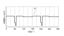
- FIG. 8 is a graph showing an example of the vane acceleration change line F1 showing the relationship between the phase of the rotor 38 (hereinafter, simply referred to as “the phase of the rotor 38”) and the acceleration of the vane 40 in the rotation direction Rd of the rotor 38. ..
- FIG. 9 is a graph showing an example of the vane velocity change line F2 showing the relationship between the phase of the rotor 38 and the moving velocity of the vane 40.
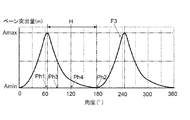
- FIG. 10 is a graph showing an example of a vane protrusion amount change curve F3 showing the relationship between the phase of the rotor 38 and the protrusion amount A of the vane 40.
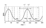
- FIG. 11 is a graph showing an example of the volume change curve F4 showing the relationship between the phase of the rotor 38 and the volume V of the first space S1.
- the phase of the rotor 38 in which the protrusion amount A of the first vane 40 is maximized is set to the first phase.
- the phase of the rotor 38 that minimizes the protrusion amount A of the first vane 40 next to the phase Ph1 and the first phase Ph1 is the second phase Ph2
- the protrusion amount A of the first vane 40 in the first phase Ph1 is Amax
- the second The protrusion amount A of the first vane 40 in the phase Ph2 is Amin
- the phase of the rotor 38 in which the protrusion amount A is half of (Amax-Amin) between the first phase Ph1 and the second phase Ph2 is the third phase Ph3.
- the phase of the midpoint H between the first phase Ph1 and the second phase Ph2 is defined as the fourth phase Ph4
- the third phase Ph3 is located between the first phase Ph1 and the fourth phase Ph4. That is, as shown in FIG.
- the vane protrusion amount change curve F3 is a graph in which the protrusion side and the return side are asymmetric with respect to the phase of the rotor 38 in which the protrusion amount A of the first vane 40 is the maximum or the minimum.
- the inner peripheral surface 42 that defines the protrusion amount A of the vane 40 so that the vane protrusion amount change curve F3 satisfies the above-mentioned feature of FIG. 10 has a shape like the inner peripheral surface 42A shown in FIG. 5 in a plan view. Is.
- the amount of compression (first space S1) in the compression step that is, the step in which the volume V of the first space S1 is reduced as compared with the case where the third phase Ph3 is located in the fourth phase Ph4 or later, for example.
- the pressure in the first space S1 at the time of starting the exhaust can be increased by increasing the amount of decrease in the volume V of the above.
- the vane velocity change line F2 advances in phase.
- a first section Z1 in which the speed of the first vane 40 increases as the speed increases is included between the first phase Ph1 and the second phase Ph2.
- the slope of the velocity that is, the acceleration illustrated in FIG. 8 becomes smaller as the phase advances.
- the volume change on the compression start side can be made larger than the volume change on the compression end side in the compression step, that is, the stroke on the exhaust side where the volume in the first space S1 decreases. .. That is, in the compression step in the vane protrusion amount change curve F3, the pressure in the first space S1 at the start of exhaust is increased by making the volume change on the compression start side larger than the volume change on the compression end side. can do.
- the velocity gradient may be gradually reduced as the phase advances.
- the slope of the velocity of the vane 40 decreases in two steps as the phase advances.
- the change in the velocity inclination (acceleration) of the vane 40 on the exhaust side may be three or more steps.
- the vane velocity change line F2 may continuously decrease the slope of the velocity of the vane 40 as the phase advances in the first section Z1.
- the volume change on the compression start side can be made larger than the volume change on the compression end side in the compression step, that is, the stroke on the exhaust side where the volume in the first space S1 decreases. .. That is, in the compression step in the vane protrusion amount change curve F3, the pressure in the first space S1 at the start of exhaust is increased by making the volume change on the compression start side larger than the volume change on the compression end side. can do.
- the phase of the rotor 38 corresponding to the minimum value of the volume V is set to the fifth phase Ph5, and the volume change curve in the section where the volume V decreases.
- the phase located next to the fifth phase Ph5 is the sixth phase Ph6, the angle from the fifth phase Ph5 to the sixth phase Ph6 is ⁇ 1, and one cycle of the volume change curve F4.
- the inner peripheral surface 42A of the pump chamber 5 is configured to satisfy ⁇ 1 / ⁇ 2 ⁇ 3/4.
- the volume change on the compression start side can be made larger than the volume change on the compression end side in the compression step, that is, on the exhaust side where the volume in the first space S1 decreases. That is, in the compression step on the volume change curve F4, the pressure in the first space S1 at the start of exhaust is increased by making the volume change on the compression start side larger than the volume change on the compression end side. Can be done.
- FIG. 12 is a perspective view schematically illustrating a vane pump according to another embodiment.
- the inner peripheral surface 42 of the pump chamber 5 is the rotation of the inner peripheral surface 42 and the rotor 38.
- the distance L from the center C may be configured to have a maximum value Lmax at three angular positions P2, P4, and P6 that are equidistant to the circumferential direction Cd of the rotor 38.
- the inner peripheral surface 42 is configured such that the distance L becomes the minimum value Lmin at the three angular positions P1, P3, and P5 that are equidistant to the circumferential direction Cd of the rotor 38.
- the vane pump 2 having such a configuration, the above-mentioned benefits of the present disclosure can be enjoyed even in the vane pump 2 in which the intake process and the exhaust process are performed three times (three cycles) for each rotation of the rotor 38. Further, in another embodiment, the vane pump may be configured such that the intake process and the exhaust process are performed four times (4 cycles) or more for each rotation of the rotor.
- the present invention is not limited to the above-described embodiment, and includes a modified form of the above-described embodiment and a combination of these embodiments.
- a plurality of slits 36 and a plurality of vanes 40 six slits 36 arranged at equal intervals in the circumferential direction Cd of the rotor 38 and six slits 36 arranged in each slit 36, respectively.
- the configuration including one vane 40 has been illustrated, the number of slits 36 and vanes 40 is not limited to 6, and may be, for example, 2 to 5, or 7 or more.
Landscapes
- Engineering & Computer Science (AREA)
- Mechanical Engineering (AREA)
- General Engineering & Computer Science (AREA)
- Rotary Pumps (AREA)
- Applications Or Details Of Rotary Compressors (AREA)
Abstract
ベーンポンプ(2)は、ポンプ室(5)を含むポンプケーシング(10)と、ポンプ室に配置され外周面(32)に複数のスリット(36)を含むロータ(38)と、複数のスリットにそれぞれ配置された複数のベーン(40)とを備える。ポンプ室は、ロータの回転中心(C)との距離(L)がロータの周方向(Cd)に変化するように形成された内周面(42)を含み、内周面は、当該内周面とロータの回転中心との距離が最小である周方向の第1角度位置(P1)から、ロータの回転方向(Rd)における第1角度位置の下流側において距離が最大である角度位置のうち最上流に位置する第2角度位置(P2)までの角度をθ1、第2角度位置から、回転方向において第2角度位置の下流側で距離が最小である角度位置のうち最上流に位置する第3角度位置(P3)までの角度をθ2とした場合にθ1<θ2/2を満たす。
Description
本開示は、ベーンポンプに関する。
従来、例えば特許文献1に開示されるように、自動車等の車両におけるブレーキブースターの負圧室内を負圧にするためのベーンポンプが知られている。ベーンポンプは、外周面にスリットが形成されたロータと該スリットに配置されたベーンとを備えており、ロータの回転によりベーンが遠心力でポンプ室のカム面に押し付けられながらカム面上を摺動するように構成されている。
ところで、ベーンポンプにおいては、一般的に排気ポートの圧力(出口圧力)よりも吸気ポートの圧力(入口圧力)が低いため、ポンプ室内に吸入された流体は排気前に圧縮されて排気される。しかし、特許文献1に開示されたような従来のベーンポンプは、ポンプ室内に収納されるロータの回転軸線方向視において、ポンプ室の内周面のプロファイルが、ロータの回転中心と該回転中心からポンプ室の内周面までの距離が最大である内周面上の点とを結ぶ線(例えば楕円の長軸を含む)を挟んで、吸気通路に連通する吸気側と排気通路に連通する排気側とが線対象の形状(例えば楕円形を含む)に形成されていた。かかる従来のベーンポンプの場合、排気通路とポンプ室とが連通して排気が始まる際におけるポンプ室内の圧力が上記出口圧力に満たないことがあり、一時的に排気通路からポンプ室内に流体が逆流してポンプ効率が低下する虞があった。特許文献1には、このような問題を解決するための方策が何ら開示されていない。
上述の事情に鑑みて、本開示の少なくとも1つの実施形態は、ポンプ効率を向上できるベーンポンプを提供することを目的とする。
(1)本発明の少なくとも1つの実施形態に係るベーンポンプは、
ポンプ室を形成するポンプケーシングと、
ポンプ室に配置され、外周面に複数のスリットが形成されたロータと、
複数のスリットにそれぞれ配置された複数のベーンと、を備え、
ポンプ室は、ロータの回転中心との距離がロータの周方向に変化するように形成された内周面を含み、
ポンプ室の内周面は、
内周面とロータの回転中心との距離が最小である周方向の第1角度位置から、ロータの回転方向における第1角度位置の下流側において距離が最大である角度位置のうち最上流に位置する第2角度位置までの角度をθ1、
第1角度位置から、回転方向において第2角度位置の下流側において距離が最小である角度位置のうち最上流に位置する第3角度位置までの角度をθ2、
と定義した場合に、θ1<θ2/2を満たすように構成されている。
ポンプ室を形成するポンプケーシングと、
ポンプ室に配置され、外周面に複数のスリットが形成されたロータと、
複数のスリットにそれぞれ配置された複数のベーンと、を備え、
ポンプ室は、ロータの回転中心との距離がロータの周方向に変化するように形成された内周面を含み、
ポンプ室の内周面は、
内周面とロータの回転中心との距離が最小である周方向の第1角度位置から、ロータの回転方向における第1角度位置の下流側において距離が最大である角度位置のうち最上流に位置する第2角度位置までの角度をθ1、
第1角度位置から、回転方向において第2角度位置の下流側において距離が最小である角度位置のうち最上流に位置する第3角度位置までの角度をθ2、
と定義した場合に、θ1<θ2/2を満たすように構成されている。
(2)本発明の少なくとも1つの実施形態に係るベーンポンプは、
ポンプ室を形成するポンプケーシングと、
ポンプ室に配置され、外周面に複数のスリットが形成されたロータと、
複数のスリットにそれぞれ配置された複数のベーンと、を備え、
ポンプ室は、ロータの回転中心との距離がロータの周方向に変化するように形成された内周面を含み、
ロータの回転方向におけるロータの位相と、複数のベーンのうち第1ベーンがロータの外周面から突出する突出量との関係を示す突出量変化曲線において、
第1ベーンの突出量が最大となるロータの位相を第1位相、第1位相の次に第1ベーンの突出量が最小となるロータの位相を第2位相、第1位相における第1ベーンの突出量をAmax、第2位相における第1ベーンの突出量をAmin、第1位相と第2位相との間において突出量が(Amax-Amin)の半分となるロータの位相を第3位相、第1位相と第2位相との中点の位相を第4位相と定義した場合に、
第3位相は、第1位相と第4位相との間に位置する。
ポンプ室を形成するポンプケーシングと、
ポンプ室に配置され、外周面に複数のスリットが形成されたロータと、
複数のスリットにそれぞれ配置された複数のベーンと、を備え、
ポンプ室は、ロータの回転中心との距離がロータの周方向に変化するように形成された内周面を含み、
ロータの回転方向におけるロータの位相と、複数のベーンのうち第1ベーンがロータの外周面から突出する突出量との関係を示す突出量変化曲線において、
第1ベーンの突出量が最大となるロータの位相を第1位相、第1位相の次に第1ベーンの突出量が最小となるロータの位相を第2位相、第1位相における第1ベーンの突出量をAmax、第2位相における第1ベーンの突出量をAmin、第1位相と第2位相との間において突出量が(Amax-Amin)の半分となるロータの位相を第3位相、第1位相と第2位相との中点の位相を第4位相と定義した場合に、
第3位相は、第1位相と第4位相との間に位置する。
(3)幾つかの実施形態では、上記(1)に記載のベーンポンプにおいて、
ロータの回転方向におけるロータの位相と、複数のベーンのうち第1ベーンがロータの外周面から突出する突出量との関係を示す突出量変化曲線において、
第1ベーンの突出量が最大となるロータの位相を第1位相、第1位相の次に第1ベーンの突出量が最小となるロータの位相を第2位相、第1位相における第1ベーンの突出量をAmax、第2位相における第1ベーンの突出量をAmin、第1位相と第2位相との間において突出量が(Amax-Amin)の半分となるロータの位相を第3位相、第1位相と第2位相との中点の位相を第4位相と定義した場合に、
第3位相は、第1位相と第4位相との間に位置していてもよい。
ロータの回転方向におけるロータの位相と、複数のベーンのうち第1ベーンがロータの外周面から突出する突出量との関係を示す突出量変化曲線において、
第1ベーンの突出量が最大となるロータの位相を第1位相、第1位相の次に第1ベーンの突出量が最小となるロータの位相を第2位相、第1位相における第1ベーンの突出量をAmax、第2位相における第1ベーンの突出量をAmin、第1位相と第2位相との間において突出量が(Amax-Amin)の半分となるロータの位相を第3位相、第1位相と第2位相との中点の位相を第4位相と定義した場合に、
第3位相は、第1位相と第4位相との間に位置していてもよい。
(4)幾つかの実施形態では、上記(2)又は(3)に記載のベーンポンプにおいて、
ロータの回転方向におけるロータの位相と、第1ベーンの突出方向における第1ベーンの速度との関係を示すベーン速度変化線は、第1位相と前記第2位相の間において、位相が進むにつれて速度が上昇する第1区間を含み、
第1区間では、位相が進むにつれて速度の傾きが小さくなっていてもよい。
ロータの回転方向におけるロータの位相と、第1ベーンの突出方向における第1ベーンの速度との関係を示すベーン速度変化線は、第1位相と前記第2位相の間において、位相が進むにつれて速度が上昇する第1区間を含み、
第1区間では、位相が進むにつれて速度の傾きが小さくなっていてもよい。
(5)幾つかの実施形態では、上記(4)に記載のベーンポンプにおいて、
第1区間では、位相が進むにつれて速度の傾きが段階的に小さくなっていてもよい。
第1区間では、位相が進むにつれて速度の傾きが段階的に小さくなっていてもよい。
(6)幾つかの実施形態では、上記(1)~(5)の何れか一つに記載のベーンポンプにおいて、
ポンプ室のうち隣り合う2つのベーンで画定される第1空間の圧力が大気圧以上に昇圧されてから、第1空間とポンプ室の排気ポートとが連通するように構成されていてもよい。
ポンプ室のうち隣り合う2つのベーンで画定される第1空間の圧力が大気圧以上に昇圧されてから、第1空間とポンプ室の排気ポートとが連通するように構成されていてもよい。
(7)幾つかの実施形態では、上記(1)~(6)の何れか一つに記載のベーンポンプにおいて、
ポンプ室の内周面は、
内周面とロータの回転中心との距離が、回転中心に対して対称である2つの角度位置において最大値を有するように構成されていてもよい。
ポンプ室の内周面は、
内周面とロータの回転中心との距離が、回転中心に対して対称である2つの角度位置において最大値を有するように構成されていてもよい。
(8)幾つかの実施形態では、上記(1)~(6)の何れか一つに記載のベーンポンプにおいて、
ポンプ室の内周面は、
内周面とロータの回転中心との距離が、ロータの周方向に等間隔である3つの角度位置において最大値を有するように構成されていてもよい。
ポンプ室の内周面は、
内周面とロータの回転中心との距離が、ロータの周方向に等間隔である3つの角度位置において最大値を有するように構成されていてもよい。
(9)幾つかの実施形態では、上記(1)~(8)の何れか一つに記載のベーンポンプにおいて、
ポンプ室の内周面は、
ロータの回転方向におけるロータの位相と、ポンプ室のうち隣り合う2つのベーンで画定される第1空間の容積との関係を表す容積変化曲線において、容積の最小値に対応するロータの位相を第5位相、容積の減少する区間における容積変化曲線の変曲点に対応する位相のうち第5位相に最も近い位相を第6位相、第5から第6位相までの角度をα1、容積変化曲線の1周期に対応する角度をα2とした場合に、α1/α2<3/4を満たしてもよい。
ポンプ室の内周面は、
ロータの回転方向におけるロータの位相と、ポンプ室のうち隣り合う2つのベーンで画定される第1空間の容積との関係を表す容積変化曲線において、容積の最小値に対応するロータの位相を第5位相、容積の減少する区間における容積変化曲線の変曲点に対応する位相のうち第5位相に最も近い位相を第6位相、第5から第6位相までの角度をα1、容積変化曲線の1周期に対応する角度をα2とした場合に、α1/α2<3/4を満たしてもよい。
本開示の少なくとも1つの実施形態によれば、ポンプ効率を向上できるベーンポンプを提供することができる。
以下、添付図面を参照して本発明の幾つかの実施形態について説明する。ただし、実施形態として記載されている又は図面に示されている構成部品の寸法、材質、形状、その相対的配置等は、本発明の範囲をこれに限定する趣旨ではなく、単なる説明例にすぎない。
例えば、「ある方向に」、「ある方向に沿って」、「平行」、「直交」、「中心」、「同心」或いは「同軸」等の相対的或いは絶対的な配置を表す表現は、厳密にそのような配置を表すのみならず、公差、若しくは、同じ機能が得られる程度の角度や距離をもって相対的に変位している状態も表すものとする。
例えば、「同一」、「等しい」及び「均質」等の物事が等しい状態であることを表す表現は、厳密に等しい状態を表すのみならず、公差、若しくは、同じ機能が得られる程度の差が存在している状態も表すものとする。
例えば、四角形状や円筒形状等の形状を表す表現は、幾何学的に厳密な意味での四角形状や円筒形状等の形状を表すのみならず、同じ効果が得られる範囲で、凹凸部や面取り部等を含む形状も表すものとする。
一方、一の構成要素を「備える」、「具える」、「具備する」、「含む」、又は、「有する」という表現は、他の構成要素の存在を除外する排他的な表現ではない。
例えば、「ある方向に」、「ある方向に沿って」、「平行」、「直交」、「中心」、「同心」或いは「同軸」等の相対的或いは絶対的な配置を表す表現は、厳密にそのような配置を表すのみならず、公差、若しくは、同じ機能が得られる程度の角度や距離をもって相対的に変位している状態も表すものとする。
例えば、「同一」、「等しい」及び「均質」等の物事が等しい状態であることを表す表現は、厳密に等しい状態を表すのみならず、公差、若しくは、同じ機能が得られる程度の差が存在している状態も表すものとする。
例えば、四角形状や円筒形状等の形状を表す表現は、幾何学的に厳密な意味での四角形状や円筒形状等の形状を表すのみならず、同じ効果が得られる範囲で、凹凸部や面取り部等を含む形状も表すものとする。
一方、一の構成要素を「備える」、「具える」、「具備する」、「含む」、又は、「有する」という表現は、他の構成要素の存在を除外する排他的な表現ではない。
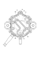
先ず、本開示の一実施形態に係るベーンポンプの概略構成について説明する。図1は、一実施形態に係るベーンポンプ2を示す概略的な分解斜視図である。図2は、図1に示したベーンポンプ2の一部切り欠き断面図である。図3は、ポンプカバー18を上方から視た図である。図4は、一実施形態におけるポンプ室5の構成例を示す平面図である。図示する例示的なベーンポンプ2は、自動車等の車両におけるブレーキブースター(マスターバック)の負圧室内を負圧にするための電動バキュームポンプである。以下において「上」及び「下」とは、ベーンポンプ2が車両に設置された状態における「上」及び「下」を意味する。
図1及び図2に示すように、ベーンポンプ2は、ポンプ室5を形成するポンプケーシング10と、ポンプ室5に配置され、外周面32に複数のスリット36が形成されたロータ38と、複数のスリット36にそれぞれ配置された複数のベーン40と、を備えている。また、ベーンポンプ2は、ロータ38を回転させるための駆動装置としてのモータ66を備えている。
ポンプケーシング10は、例えば図1及び図2に示すように、ロータ38及び複数のベーン40で構成される可動部4としてのロータ組立体が配置されるポンプ室5と、ポンプ室5に気体を導くための吸気通路6と、ポンプ室5から気体を外部に導くための排気通路8と、を含む。また、図1~図3に示すように、ポンプケーシング10は、可動部4の一方側(上側)を覆うポンプカバー18と、ポンプカバー18の上側を覆うトップカバー44と、を含む。ポンプケーシング10のポンプケーシング本体16は、ロータ38の外周面32と対向する内周面42を含む。
可動部4は、モータ66に駆動されてポンプ室5への気体の吸込及びポンプ室5からの気体の吐出を行うことで気体を移送する。可動部4におけるロータ38の外周面32は、平面視において円形状を呈するようになっていてもよい。このように、ベーンポンプ2は、モータ66の不図示のシャフトに連結されたロータ38をモータ66で回転させることにより、例えば図4に示すように、ロータ38のスリット36に沿ってベーン40が遠心力でロータ38の径方向Dの外側(より詳細には、ロータ38の回転軸線方向視においてベーン40がロータ38の外周面32からスリット36の延在方向に沿って突出する突出方向Pd)に向けて移動し、ベーン40の先端部13が内周面42上を摺動するように構成されている。
スリット36は、例えば図4に示すように、ロータ38の径方向Dにおける内側に向かうにつれてロータ38の回転方向Rdにおける上流側に向かうように平面視において直線状に形成されていてもよい。この場合、ベーン40は、スリット36の内壁に沿って摺動可能な幅(厚さ)を有する板状に形成されてもよい。以下において、ベーンポンプ2におけるロータ38の軸方向を単に「軸方向」といい、ロータ38の周方向Cdを単に「周方向」といい、ロータ38の回転方向Rdを単に「回転方向」といい、ロータ38の径方向Dを単に「径方向」ということがある。また、「回転方向Rdにおける上流側」とは、ロータ38の回転方向Rdとは逆方向を意味し、「回転方向Rdにおける下流側」とは、ロータ38の回転が進む方向を意味することとする。なお、図1に示すように、ベーンポンプ2では、軸方向において、ロータ38側(上記カバー部分側)が上側であり、モータ66側が下側である。
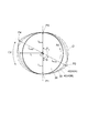
ここで、ポンプ室5の内周面42について更に詳細に説明する。図5は、幾つかの実施形態における内周面42(42A,42B)の形状を例示する図である。図3~図5に例示するように、ポンプ室5は、図1及び図2に示すポンプケーシング本体16の内周面42および底面と、ポンプカバー18の下面とで画定される。内周面42は、ロータ38の外周面32から図4に示すロータ38の径方向Dの外側(詳細には突出方向Pd)に向かうベーン40の突出量Aを規定するカム面として機能する。かかるポンプ室5の内周面42は、ロータ38の回転中心Cとの距離Lがロータ38の周方向Cdに周期的に変化するように形成されている。具体的に、内周面42(42A,42B)は、当該内周面42とロータ38の回転中心Cとの距離Lが最小(Lmin)である周方向Cdの第1角度位置P1から、ロータ38の回転方向Rdにおける第1角度位置P1の下流側において距離Lが最大(Lmax)である角度位置のうち最上流に位置する第2角度位置P2までの角度をθ1、第1角度位置P1から、回転方向Rdにおいて第2角度位置P2の下流側において距離Lが最小(Lmin)である角度位置のうち最上流に位置する第3角度位置P3までの角度をθ2と定義した場合に、θ1<θ2/2を満たす。
つまり、内周面42は、ともに距離Lが最小値Lminである第1角度位置P1から第3角度位置P3までの角度θ2の半分に相当する角度位置よりもロータ38の回転方向Rdの上流側に、距離Lが最大値Lmaxである第2角度位置P2が位置するように構成される。すなわち、ロータ38の回転中心Cとの距離Lが最大である第2角度位置P2が、ロータ38の回転方向Rdにおいて第2角度位置P2より上流側と下流側とでそれぞれ最も近くで距離Lが最小である第1角度位置P1と第3角度位置P3との中点よりも回転方向Rdの上流側に位置する。例えば図3~図5に例示するように、ロータ38の1回転につき吸気工程と排気工程とがそれぞれ2回(2サイクル)行われるベーンポンプ2の場合、θ2=180°、且つθ1<90°である。なお、最大値Lmaxは、回転方向Rdにおける前後近傍の距離Lと比較した最大値である極大値であってもよい。同様に、最小値Lminは、回転方向Rdにおける前後近傍の距離Lと比較した最小値である極小値であってもよい。また、周方向Cdの全周に亘って、各々の最大値Lmaxが同一の値であってもよいし、各々の最小値Lminが同一の値であってもよい。
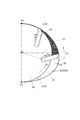
ここで、ポンプ室5のうちロータ38の周方向Cdにおいて隣り合う2つのベーン40の間の第1空間S1の容積Vの変化について説明する。図6は、幾つかの実施形態に係るベーンポンプ2における第1空間S1の容積Vの変化を例示する図である。図7は、一実施形態に係るポンプ室5の構成例を示す概略図である。
ポンプ室5には、例えば図4に例示するように、第1角度位置P1と第2角度位置P2との間に図2及び図3に示す吸気通路6が連通しており、第2角度位置P2と第3角度位置P3との間に排気通路8が連通している。ポンプ室5のうち第1空間S1内の容積Vは、隣り合う2つのベーン40の突出量Aに応じて変化する。本開示におけるベーン40の突出量Aは、例えば図4におけるロータ38の外周面32からベーン40の先端(径方向外側端)までの、スリット36の延在方向に沿った距離である。
第1空間S1の容積Vは、具体的には、図6に示すように周期的に変化し、2つのベーン40が距離Lが最小である角度位置を挟んだ位置にあるときに最小となり、2つのベーン40が距離Lが最大である角度位置を挟んだ位置にあるときに最大となる。従って、ベーンポンプ2は、ロータ38の回転に伴い、距離Lが最小から最大に向かう容積拡大の際に吸気し、図7に例示するような距離Lが最大から最小に向かう容積縮小の際に排気する。排気通路8からポンプ室5への逆流を防ぐ観点において、排気の際は、ポンプ室5内の流体を排気前に排気通路8(排気出口)の圧力以上に圧縮(昇圧)してポンプ室5外に排出することが好ましい。
ポンプ室5には、例えば図4に例示するように、第1角度位置P1と第2角度位置P2との間に図2及び図3に示す吸気通路6が連通しており、第2角度位置P2と第3角度位置P3との間に排気通路8が連通している。ポンプ室5のうち第1空間S1内の容積Vは、隣り合う2つのベーン40の突出量Aに応じて変化する。本開示におけるベーン40の突出量Aは、例えば図4におけるロータ38の外周面32からベーン40の先端(径方向外側端)までの、スリット36の延在方向に沿った距離である。
第1空間S1の容積Vは、具体的には、図6に示すように周期的に変化し、2つのベーン40が距離Lが最小である角度位置を挟んだ位置にあるときに最小となり、2つのベーン40が距離Lが最大である角度位置を挟んだ位置にあるときに最大となる。従って、ベーンポンプ2は、ロータ38の回転に伴い、距離Lが最小から最大に向かう容積拡大の際に吸気し、図7に例示するような距離Lが最大から最小に向かう容積縮小の際に排気する。排気通路8からポンプ室5への逆流を防ぐ観点において、排気の際は、ポンプ室5内の流体を排気前に排気通路8(排気出口)の圧力以上に圧縮(昇圧)してポンプ室5外に排出することが好ましい。
この点、上述した本開示のベーンポンプ2によれば、上記(1)式を満たすことにより、従来のベーンポンプ(例えばθ1=θ2/2を満たすベーンポンプ)に比べてより上流側の角度位置で圧縮工程に移行することができるため、圧縮工程を長くすることができる。よって、ポンプ室5内と排気通路8とが連通して排気が開始される際における第1空間S1内の圧力を従来よりも高くすることができる。これにより、排気通路8からポンプ室5内への流体の逆流を効果的に抑制してポンプ効率の向上を図ることができるベーンポンプ2を提供することができる。
また、ポンプ効率が向上することにより、省エネ化(低消費電力化)を図ることができる。また、負荷トルクが低下するため、例えば従来と同一性能のモータを使用する際には回転速度が上昇することにより排気に要する時間を短縮できるから、真空性能が向上する。また、負荷トルクの低下によりベーンポンプ2での発熱量が低減されるため、熱膨張によるベーンポンプ2内部のクリアランスの変化が減少し、真空性能の温度特性が改善される。
また、ベーンポンプ2での発熱量が低減されることにより、例えばロータ38、ベーン40及びポンプケーシング10の摩耗量が低減され、ポンプ部分の寿命を改善することができる。また、負荷トルク及びベーンポンプ2の発熱量が低減されることにより、モータ66の寿命も改善することができる。また、ベーンポンプ2の稼働中における製品全体の温度が低下するため、耐熱性の低い材料を採用することができる。さらに、第1空間S1内の容積変化を大きく確保することができることにより、例えば1つのロータ38に設けるベーン40の枚数を低減することができる。
幾つかの実施形態では、例えば図3~図5に例示するように、ポンプ室5の内周面42(42A,42B)は、内周面42とロータ38の回転中心Cとの距離Lが、回転中心Cに対して対称である2つの角度位置において最大値Lmaxとなるように構成されている。この場合、2つの第2角度位置P2、P4は、ロータ38の回転軸線方向視において互いが回転中心Cに対して点対称の位置に配置され得る。また、この場合、例えば図4及び図5において、角度位置P3は第2角度位置P4との関係において第1角度位置であり、角度位置P1は第2角度位置P4との関係において第3角度位置である。
このように、距離Lが、回転中心Cに対して対称である2つの角度位置において最大値Lmaxとなる構成では、例えば排気通路8と吸気通路6とが1つずつ設けられ、ロータ38の1回転につき吸気工程と排気工程とがそれぞれ1回(1サイクル)行われるベーンポンプ(距離Lが1つの角度位置のみで最大値Lmaxとなる構成)と比較して、圧縮工程が短くなりやすい。このように圧縮工程が短くなりやすい構成においても、上記(1)式を満たすようにベーンポンプ2を構成することにより、圧縮工程を長くして上述の逆流を抑制することができる。
幾つかの実施形態では、上述したベーンポンプ2は、ポンプ室5のうち隣り合う2つのベーン40で画定される第1空間S1の圧力が大気圧以上に昇圧されてから、第1空間S1と排気口14(より詳細にはポンプ室5に開口された排気通路8の排気ポート35)とが連通するように構成されていてもよい。第1空間S1とポンプ室5の排気ポート35とが連通する前に第1空間S1内の圧力が大気圧以上に昇圧される内周面42のプロファイルは、ロータ38の周方向Cdに配置されるベーン40の数や、周方向Cdにおいて吸気通路6及び排気通路8とポンプ室5とが連通する位置とを考慮して予め試験を行うことにより設定することができる。
車両におけるブレーキブースターの負圧室内を負圧にするためのベーンポンプ2においては、排気口14が大気に向けて開放されており、排気通路8内の圧力が大気圧であることが多い。従って、第1空間S1の圧力を大気圧以上に昇圧してから、第1空間S1とポンプ室5の排気ポート35とが連通される構成によれば、第1空間S1とポンプ室5の排気ポート35との連通が開始される際における第1空間S1内の圧力を排気通路8内の圧力よりも高くすることができるから、排気通路8からポンプ室5の第1空間S1内への流体の逆流を効果的に抑制することができる。
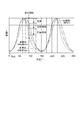
図8は、ロータ38の回転方向Rdにおけるロータ38の位相(以下、単に「ロータ38の位相」という。)とベーン40の加速度との関係を示すベーン加速度変化線F1の一例を示すグラフである。図9は、ロータ38の位相とベーン40の移動速度との関係を示すベーン速度変化線F2の一例を示すグラフである。図10は、ロータ38の位相とベーン40の突出量Aとの関係を示すベーン突出量変化曲線F3の一例を示すグラフである。図11は、ロータ38の位相と第1空間S1の容積Vとの関係を示す容積変化曲線F4の一例を示すグラフである。
本発明の少なくとも1つの実施形態に係るベーンポンプ2は、例えば図10に例示するように、ベーン突出量変化曲線F3において、第1ベーン40の突出量Aが最大となるロータ38の位相を第1位相Ph1、第1位相Ph1の次に第1ベーン40の突出量Aが最小となるロータ38の位相を第2位相Ph2、第1位相Ph1における第1ベーン40の突出量AをAmax、第2位相Ph2における第1ベーン40の突出量AをAmin、第1位相Ph1と第2位相Ph2との間において突出量Aが(Amax-Amin)の半分となるロータ38の位相を第3位相Ph3、第1位相Ph1と第2位相Ph2との中点Hの位相を第4位相Ph4と定義した場合に、第3位相Ph3は、第1位相Ph1と第4位相Ph4との間に位置する。
つまり、図10に示すように、ベーン突出量変化曲線F3は、第1ベーン40の突出量Aが最大又は最小であるロータ38の位相を挟んで、突出側と戻り側とが非対称のグラフとなる。なお、ベーン突出量変化曲線F3が図10の上記特徴を満たすようにベーン40の突出量Aを規定する内周面42は、平面視にて例えば図5に示す内周面42Aのような形状である。
本発明の少なくとも1つの実施形態に係るベーンポンプ2は、例えば図10に例示するように、ベーン突出量変化曲線F3において、第1ベーン40の突出量Aが最大となるロータ38の位相を第1位相Ph1、第1位相Ph1の次に第1ベーン40の突出量Aが最小となるロータ38の位相を第2位相Ph2、第1位相Ph1における第1ベーン40の突出量AをAmax、第2位相Ph2における第1ベーン40の突出量AをAmin、第1位相Ph1と第2位相Ph2との間において突出量Aが(Amax-Amin)の半分となるロータ38の位相を第3位相Ph3、第1位相Ph1と第2位相Ph2との中点Hの位相を第4位相Ph4と定義した場合に、第3位相Ph3は、第1位相Ph1と第4位相Ph4との間に位置する。
つまり、図10に示すように、ベーン突出量変化曲線F3は、第1ベーン40の突出量Aが最大又は最小であるロータ38の位相を挟んで、突出側と戻り側とが非対称のグラフとなる。なお、ベーン突出量変化曲線F3が図10の上記特徴を満たすようにベーン40の突出量Aを規定する内周面42は、平面視にて例えば図5に示す内周面42Aのような形状である。
かかる構成のベーンポンプ2によれば、例えば第3位相Ph3が第4位相Ph4以降に位置する場合に比べて、圧縮工程すなわち第1空間S1の容積Vが減少する工程における圧縮量(第1空間S1の容積Vの減少量)を大きくすることにより、排気を開始する際における第1空間S1内の圧力を大きくすることができる。つまり、上述したθ1<θ2/2を満たす構成では、θ1=θ2/2の場合に比べて圧縮工程に移行するタイミングを早めることにより、排気が開始される際における第1空間S1内の圧力を従来よりも高めることが可能であるのに対し、第3位相Ph3が第1位相Ph1と第4位相Ph4との間に位置する構成では、容積Vの減少工程(圧縮工程)全体における前半での圧縮量を後半での圧縮量よりも大きく確保することにより排気が開始される際における第1空間S1内の圧力を従来よりも高めるができる。これにより、排気通路8からポンプ室5内への流体の逆流を効果的に抑制してポンプ効率を向上可能なベーンポンプ2を提供することができる。
幾つかの実施形態では、例えば図9に例示するように、第3位相Ph3が第1位相Ph1と第4位相Ph4との間に位置するベーンポンプ2において、ベーン速度変化線F2は、位相が進むにつれて第1ベーン40の速度が上昇する第1区間Z1を第1位相Ph1と第2位相Ph2の間に含む。第1区間Z1では、位相が進むにつれて速度の傾き(つまり図8に例示する加速度)が小さくなる。
かかる構成のベーンポンプ2によれば、圧縮工程すなわち第1空間S1内の容積が減少する排気側の行程において、圧縮の開始側の容積変化を圧縮の終了側の容積変化よりも大きくすることができる。つまり、ベーン突出量変化曲線F3における圧縮工程において、圧縮の開始側の容積変化を圧縮の終了側の容積変化よりも大きくすることにより、排気が開始する際における第1空間S1内の圧力を大きくすることができる。
幾つかの実施形態では、例えば図9に例示するように、ベーン速度変化線F2の第1区間Z1では、位相が進むにつれて速度の傾きが段階的に小さくなっていてもよい。例えば図9に示す例では、第1区間Z1において、位相が進むにつれてベーン40の速度の傾きが2段階に小さくなる。なお、排気側におけるベーン40の速度の傾き(加速度)の変化は3段階以上であってもよい。また、他の実施形態では、ベーン速度変化線F2は、第1区間Z1において、位相が進むにつれてベーン40の速度の傾きが連続的に小さくなってもよい。
かかる構成のベーンポンプ2によれば、圧縮工程すなわち第1空間S1内の容積が減少する排気側の行程において、圧縮の開始側の容積変化を圧縮の終了側の容積変化よりも大きくすることができる。つまり、ベーン突出量変化曲線F3における圧縮工程において、圧縮の開始側の容積変化を圧縮の終了側の容積変化よりも大きくすることにより、排気が開始する際における第1空間S1内の圧力を大きくすることができる。
幾つかの実施形態では、例えば図11に例示するように、容積変化曲線F4において、容積Vの最小値に対応するロータ38の位相を第5位相Ph5、容積Vの減少する区間における容積変化曲線F4の変曲点Iに対応する位相のうち第5位相Ph5の次に位置する位相を第6位相Ph6、第5位相Ph5から第6位相Ph6までの角度をα1、容積変化曲線F4の1周期に対応する角度をα2とした場合に、ポンプ室5の内周面42Aは、α1/α2<3/4を満たすように構成されている。
かかる構成のベーンポンプ2によれば、圧縮工程すなわち第1空間S1内の容積が減少する排気側において、圧縮の開始側の容積変化を圧縮の終了側の容積変化よりも大きくすることができる。つまり、容積変化曲線F4における圧縮工程において、圧縮の開始側の容積変化を圧縮の終了側の容積変化よりも大きくすることにより、排気が開始する際における第1空間S1内の圧力を大きくすることができる。
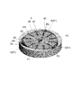
図12は、他の実施形態に係るベーンポンプを概略的に例示する斜視図である。
幾つかの実施形態では、例えば図12に例示するように、上述した何れか一つの実施形態に記載のベーンポンプ2において、ポンプ室5の内周面42は、内周面42とロータ38の回転中心Cとの距離Lが、ロータ38の周方向Cdに等間隔である3つの角度位置P2、P4、P6において最大値Lmaxを有するように構成されてもよい。この場合、内周面42は、ロータ38の周方向Cdに等間隔である3つの角度位置P1、P3、P5において距離Lが最小値Lminとなるように構成される。このように、ロータ38の1回転につき吸気工程と排気工程とがそれぞれ3回(3サイクル)行われるベーンポンプ2では、θ2=120°、且つθ1<60°を満たすように内周面42を形成してもよい。
幾つかの実施形態では、例えば図12に例示するように、上述した何れか一つの実施形態に記載のベーンポンプ2において、ポンプ室5の内周面42は、内周面42とロータ38の回転中心Cとの距離Lが、ロータ38の周方向Cdに等間隔である3つの角度位置P2、P4、P6において最大値Lmaxを有するように構成されてもよい。この場合、内周面42は、ロータ38の周方向Cdに等間隔である3つの角度位置P1、P3、P5において距離Lが最小値Lminとなるように構成される。このように、ロータ38の1回転につき吸気工程と排気工程とがそれぞれ3回(3サイクル)行われるベーンポンプ2では、θ2=120°、且つθ1<60°を満たすように内周面42を形成してもよい。
かかる構成のベーンポンプ2によれば、ロータ38の1回転につき吸気工程と排気工程とがそれぞれ3回(3サイクル)行われるベーンポンプ2においても、上述した本開示の利益を享受することができる。また、他の実施形態では、ベーンポンプは、ロータの1回転につき吸気工程と排気工程とがそれぞれ4回(4サイクル)以上行われるように構成されていてもよい。
本開示の少なくとも1つの実施形態によれば、ポンプ効率を向上できるベーンポンプ2を提供することができる。
本発明は上述した実施形態に限定されることはなく、上述した実施形態に変更を加えた形態や、これらの形態を組み合わせた形態も含む。例えば、上述した幾つかの実施形態では、複数のスリット36及び複数のベーン40として、ロータ38の周方向Cdに等間隔に配置された6つのスリット36と、各スリット36にそれぞれ配置された6つのベーン40とを含む構成を例示したが、スリット36及びベーン40の数は6つに限定されず、例えば、2~5つであってもよいし、7つ以上であってもよい。
2 ベーンポンプ
5 ポンプ室
14 排気口
32 外周面
35 排気ポート
36 スリット
38 ロータ
40 ベーン
42 内周面
S1 第1空間
F1 ベーン加速度変化線
F2 ベーン速度変化線
F3 突出量変化曲線
F4 容積変化曲線
P1 第1角度位置
P2 第2角度位置
P3 第3角度位置
Ph1 第1位相
Ph2 第2位相
Ph3 第3位相
Ph4 第4位相
Z1 第1区間
A 第1ベーンの突出量
Amax 第1ベーンの最大突出量
Amin 第1ベーンの最小突出量
C 回転中心
Cd 周方向
I 変曲点
L ポンプ室の内周面とロータの回転中心との距離
Pd ベーンの突出方向
Rd 回転方向
5 ポンプ室
14 排気口
32 外周面
35 排気ポート
36 スリット
38 ロータ
40 ベーン
42 内周面
S1 第1空間
F1 ベーン加速度変化線
F2 ベーン速度変化線
F3 突出量変化曲線
F4 容積変化曲線
P1 第1角度位置
P2 第2角度位置
P3 第3角度位置
Ph1 第1位相
Ph2 第2位相
Ph3 第3位相
Ph4 第4位相
Z1 第1区間
A 第1ベーンの突出量
Amax 第1ベーンの最大突出量
Amin 第1ベーンの最小突出量
C 回転中心
Cd 周方向
I 変曲点
L ポンプ室の内周面とロータの回転中心との距離
Pd ベーンの突出方向
Rd 回転方向
Claims (9)
- ポンプ室を形成するポンプケーシングと、
前記ポンプ室に配置され、外周面に複数のスリットが形成されたロータと、
前記複数のスリットにそれぞれ配置された複数のベーンと、を備え、
前記ポンプ室は、前記ロータの回転中心との距離が前記ロータの周方向に変化するように形成された内周面により画定され、
前記ポンプ室の前記内周面は、
当該内周面と前記ロータの前記回転中心との前記距離が最小である前記周方向の第1角度位置から、前記ロータの回転方向における前記第1角度位置の下流側において前記距離が最大である角度位置のうち最上流に位置する第2角度位置までの角度をθ1、
前記第1角度位置から、前記回転方向において前記第2角度位置の下流側において前記距離が最小である角度位置のうち最上流に位置する第3角度位置までの角度をθ2、
と定義した場合に、θ1<θ2/2を満たすように構成されている
ベーンポンプ。 - ポンプ室を形成するポンプケーシングと、
前記ポンプ室に配置され、外周面に複数のスリットが形成されたロータと、
前記複数のスリットにそれぞれ配置された複数のベーンと、を備え、
前記ポンプ室は、前記ロータの回転中心との距離が前記ロータの周方向に変化するように形成された内周面により画定され、
前記ロータの回転方向における前記ロータの位相と、前記複数のベーンのうち第1ベーンが前記ロータの前記外周面から突出する突出量との関係を示す突出量変化曲線において、
前記第1ベーンの前記突出量が最大となる前記ロータの位相を第1位相、前記第1位相の次に前記第1ベーンの前記突出量が最小となる前記ロータの位相を第2位相、前記第1位相における前記第1ベーンの前記突出量をAmax、前記第2位相における前記第1ベーンの前記突出量をAmin、前記第1位相と前記第2位相との間において前記突出量が(Amax-Amin)の半分となる前記ロータの位相を第3位相、前記第1位相と前記第2位相との中点の位相を第4位相と定義した場合に、
前記第3位相は、前記第1位相と前記第4位相との間に位置する、ベーンポンプ。 - 前記ロータの回転方向における前記ロータの位相と、前記複数のベーンのうち第1ベーンが前記ロータの前記外周面から突出する突出量との関係を示す突出量変化曲線において、
前記第1ベーンの前記突出量が最大となる前記ロータの位相を第1位相、前記第1位相の次に前記第1ベーンの前記突出量が最小となる前記ロータの位相を第2位相、前記第1位相における前記第1ベーンの前記突出量をAmax、前記第2位相における前記第1ベーンの前記突出量をAmin、前記第1位相と前記第2位相との間において前記突出量が(Amax-Amin)の半分となる前記ロータの位相を第3位相、前記第1位相と前記第2位相との中点の位相を第4位相と定義した場合に、
前記第3位相は、前記第1位相と前記第4位相との間に位置する、請求項1に記載のベーンポンプ。 - 前記ロータの回転方向における前記ロータの位相と、前記第1ベーンの突出方向における前記第1ベーンの速度との関係を示すベーン速度変化線は、前記第1位相と前記第2位相の間において、前記位相が進むにつれて前記速度が上昇する第1区間を含み、
前記第1区間では、前記位相が進むにつれて前記速度の傾きが小さくなる、請求項2又は3に記載のベーンポンプ。 - 前記第1区間では、前記位相が進むにつれて前記速度の傾きが段階的に小さくなる、請求項4に記載のベーンポンプ。
- 前記ポンプ室のうち隣り合う2つの前記ベーンで画定される第1空間の圧力が大気圧以上に昇圧されてから、前記第1空間と前記ポンプ室の排気口とが連通するように構成された、
請求項1~5の何れか一項に記載のベーンポンプ。 - 前記ポンプ室の前記内周面は、
当該内周面と前記ロータの前記回転中心との前記距離が、前記回転中心に対して対称である2つの角度位置において最大値を有するように構成された
請求項1~6の何れか一項に記載のベーンポンプ。 - 前記ポンプ室の前記内周面は、
当該内周面と前記ロータの前記回転中心との前記距離が、前記ロータの前記周方向に等間隔である3つの角度位置において最大値を有するように構成された
請求項1~6の何れか一項に記載のベーンポンプ。 - 前記ポンプ室の前記内周面は、
前記ロータの回転方向における前記ロータの位相と、前記ポンプ室のうち隣り合う2つの前記ベーンで画定される第1空間の容積との関係を表す容積変化曲線において、前記容積の最小値に対応する前記ロータの位相を第5位相、前記容積の減少する区間における前記容積変化曲線の変曲点に対応する位相のうち前記第5位相の次に位置する位相を第6位相、前記第5位相から前記第6位相までの角度をα1、前記容積変化曲線の1周期に対応する角度をα2とした場合に、α1/α2<3/4を満たすように構成されている
請求項1~8の何れか一項に記載のベーンポンプ。
Applications Claiming Priority (2)
| Application Number | Priority Date | Filing Date | Title |
|---|---|---|---|
| JP2019-102754 | 2019-05-31 | ||
| JP2019102754A JP7299759B2 (ja) | 2019-05-31 | 2019-05-31 | ベーンポンプ |
Publications (1)
| Publication Number | Publication Date |
|---|---|
| WO2020240966A1 true WO2020240966A1 (ja) | 2020-12-03 |
Family
ID=73553292
Family Applications (1)
| Application Number | Title | Priority Date | Filing Date |
|---|---|---|---|
| PCT/JP2020/009113 Ceased WO2020240966A1 (ja) | 2019-05-31 | 2020-03-04 | ベーンポンプ |
Country Status (2)
| Country | Link |
|---|---|
| JP (1) | JP7299759B2 (ja) |
| WO (1) | WO2020240966A1 (ja) |
Citations (7)
| Publication number | Priority date | Publication date | Assignee | Title |
|---|---|---|---|---|
| JPS5827895A (ja) * | 1981-08-12 | 1983-02-18 | Hitachi Ltd | ベ−ン形回転機 |
| JPS59162380A (ja) * | 1983-03-08 | 1984-09-13 | Toyota Central Res & Dev Lab Inc | 流体圧ベ−ンポンプ |
| JPS61126392A (ja) * | 1984-11-21 | 1986-06-13 | Nippon Denso Co Ltd | ベ−ン型圧縮機 |
| JPS61268894A (ja) * | 1985-05-22 | 1986-11-28 | Diesel Kiki Co Ltd | ベ−ン型圧縮機 |
| JP2002161882A (ja) * | 2000-11-28 | 2002-06-07 | Seiko Instruments Inc | 気体圧縮機 |
| JP2015059572A (ja) * | 2013-09-19 | 2015-03-30 | ヘラ・カーゲーアーアー・ヒュック・ウント・コンパニー | ベーンポンプ |
| US20180187680A1 (en) * | 2016-12-29 | 2018-07-05 | Lg Electronics Inc. | Hermetic compressor |
-
2019
- 2019-05-31 JP JP2019102754A patent/JP7299759B2/ja active Active
-
2020
- 2020-03-04 WO PCT/JP2020/009113 patent/WO2020240966A1/ja not_active Ceased
Patent Citations (7)
| Publication number | Priority date | Publication date | Assignee | Title |
|---|---|---|---|---|
| JPS5827895A (ja) * | 1981-08-12 | 1983-02-18 | Hitachi Ltd | ベ−ン形回転機 |
| JPS59162380A (ja) * | 1983-03-08 | 1984-09-13 | Toyota Central Res & Dev Lab Inc | 流体圧ベ−ンポンプ |
| JPS61126392A (ja) * | 1984-11-21 | 1986-06-13 | Nippon Denso Co Ltd | ベ−ン型圧縮機 |
| JPS61268894A (ja) * | 1985-05-22 | 1986-11-28 | Diesel Kiki Co Ltd | ベ−ン型圧縮機 |
| JP2002161882A (ja) * | 2000-11-28 | 2002-06-07 | Seiko Instruments Inc | 気体圧縮機 |
| JP2015059572A (ja) * | 2013-09-19 | 2015-03-30 | ヘラ・カーゲーアーアー・ヒュック・ウント・コンパニー | ベーンポンプ |
| US20180187680A1 (en) * | 2016-12-29 | 2018-07-05 | Lg Electronics Inc. | Hermetic compressor |
Also Published As
| Publication number | Publication date |
|---|---|
| JP7299759B2 (ja) | 2023-06-28 |
| JP2020197151A (ja) | 2020-12-10 |
Similar Documents
| Publication | Publication Date | Title |
|---|---|---|
| EP2464872B1 (en) | Balanced pressure, variable displacement, dual lobe, single ring, vane pump | |
| US7226280B1 (en) | Roots vacuum pump | |
| CN108350895B (zh) | 连结型螺纹槽间隔件及真空泵 | |
| US4762480A (en) | Rotary pump | |
| CN109477419B (zh) | 可变容量型增压器 | |
| JP2015527523A (ja) | ロータ端面シールを有するスーパーチャージャアセンブリ及びスーパーチャージャアセンブリの製造方法 | |
| WO2016071712A1 (en) | Compressor and turbocharger | |
| WO2020240966A1 (ja) | ベーンポンプ | |
| JP2004285978A (ja) | ベーン式気体ポンプ | |
| US20180223841A1 (en) | Vane pump | |
| CN110520607A (zh) | 涡轮机以及具有该涡轮机的涡轮增压器 | |
| JP6361561B2 (ja) | 流体ポンプ | |
| US7217083B2 (en) | Regenerative pump having blades received in fluid passage | |
| CN102678583B (zh) | 组装包括径向流动通道的超音速压缩机转子的系统和方法 | |
| JP2001304186A (ja) | 遠心型圧縮機のディフューザ | |
| JP5811593B2 (ja) | ガイドベーンユニットの軸受構造、及び過給機 | |
| JP2002202018A (ja) | 燃料ポンプ | |
| CN216691453U (zh) | 一种柴油发动机上真空泵结构 | |
| CN101087959A (zh) | 可变输送叶片油泵 | |
| JP6042969B2 (ja) | ベーンポンプ | |
| CN100557245C (zh) | 特别用于油的可变输送叶片泵 | |
| CN100400799C (zh) | 几何形状可变的涡轮增压器 | |
| JP2025014419A (ja) | ベーンポンプ | |
| CN209294044U (zh) | 一种压缩机用转子及其滑片空气压缩机 | |
| JP2007162483A (ja) | 過流ポンプ |
Legal Events
| Date | Code | Title | Description |
|---|---|---|---|
| 121 | Ep: the epo has been informed by wipo that ep was designated in this application |
Ref document number: 20814174 Country of ref document: EP Kind code of ref document: A1 |
|
| NENP | Non-entry into the national phase |
Ref country code: DE |
|
| 122 | Ep: pct application non-entry in european phase |
Ref document number: 20814174 Country of ref document: EP Kind code of ref document: A1 |