WO2020240846A1 - 制御装置、制御方法及びロボットシステム - Google Patents
制御装置、制御方法及びロボットシステム Download PDFInfo
- Publication number
- WO2020240846A1 WO2020240846A1 PCT/JP2019/021796 JP2019021796W WO2020240846A1 WO 2020240846 A1 WO2020240846 A1 WO 2020240846A1 JP 2019021796 W JP2019021796 W JP 2019021796W WO 2020240846 A1 WO2020240846 A1 WO 2020240846A1
- Authority
- WO
- WIPO (PCT)
- Prior art keywords
- inertial body
- component
- compensation
- armature
- torque
- Prior art date
- Legal status (The legal status is an assumption and is not a legal conclusion. Google has not performed a legal analysis and makes no representation as to the accuracy of the status listed.)
- Ceased
Links
Images







Classifications
-
- B—PERFORMING OPERATIONS; TRANSPORTING
- B25—HAND TOOLS; PORTABLE POWER-DRIVEN TOOLS; MANIPULATORS
- B25J—MANIPULATORS; CHAMBERS PROVIDED WITH MANIPULATION DEVICES
- B25J13/00—Controls for manipulators
-
- H—ELECTRICITY
- H02—GENERATION; CONVERSION OR DISTRIBUTION OF ELECTRIC POWER
- H02P—CONTROL OR REGULATION OF ELECTRIC MOTORS, ELECTRIC GENERATORS OR DYNAMO-ELECTRIC CONVERTERS; CONTROLLING TRANSFORMERS, REACTORS OR CHOKE COILS
- H02P29/00—Arrangements for regulating or controlling electric motors, appropriate for both AC and DC motors
- H02P29/40—Regulating or controlling the amount of current drawn or delivered by the motor for controlling the mechanical load
Definitions
- This disclosure relates to control devices, control methods and robot systems.
- Patent Document 1 discloses a motor control device that estimates the disturbance torque to the motor by a disturbance observer and compensates for the disturbance torque to control the motor.
- the present disclosure provides a control device, a control method, and a robot system effective for improving the stability of control.
- the control device includes a first inertial body, an armature that drives the first inertial body according to the supply of electric power, a second inertial body, and a first inertial body to a second inertial body.
- a control unit that outputs a driving force for making the driving force of the second inertial body follow the control target to the armature to be controlled having a transmission element for transmitting power, and a second inertial body generated in the controlled object. It is provided with a compensation unit that calculates a compensation component that cancels the feedback component that affects the operation of the armature based on the operating state of the controlled object and adds it to the drive power output to the armature by the control unit.
- the control method includes a first inertial body, an armature that drives the first inertial body in response to the supply of electric power, a second inertial body, and a first inertial body to a second inertial body.
- a compensation component that cancels the feedback component that affects the operation of the armature is calculated based on the operating state of the controlled object, and added to the drive power output to the armature.
- the robot system includes a first inertial body, an armature that drives the first inertial body in response to power supply, a second inertial body, and a first inertial body to a second inertial body.
- a robot having a transmission element that transmits power to the body, a control unit that outputs a driving force for making the acceleration of the second inertial body follow the target acceleration, and an influence on the operation of the second inertial body generated in the robot. It is provided with a compensation unit that calculates a compensation component that cancels the feedback component based on the operating state of the robot and adds the compensation component to the drive power output to the armature by the control unit.
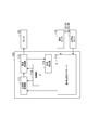
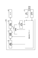
- the robot system 1 is a system that operates the robot according to a preset control target. As illustrated in FIG. 1, the robot system 1 includes a robot 10 as an example of a control target and a controller 100.
- the robot 10 is, for example, a 6-axis vertical articulated robot, and has a base 11, a swivel portion 12, a first arm 13, a second arm 14, a wrist portion 15, a tip portion 16, and actuators 41 and 42. , 43, 44, 45, 46 and acceleration sensors 51, 52, 53, 54, 55, 56.
- the base 11 is fixed to the floor surface, a dolly, or the like.
- the swivel portion 12 is provided on the base portion 11 and can swivel around the vertical axis 21. That is, the robot 10 has a joint 31 that allows the swivel portion 12 to swivel around the axis 21.
- the first arm 13 extends from the swivel portion 12 and can swing around the axis 22 intersecting (for example, orthogonal to) the axis 21. That is, the robot 10 has a joint 32 that allows the first arm 13 to swing around the axis 22.
- the intersection here includes an intersection in a state of being twisted with each other like a so-called grade separation. The same applies to the following.
- the second arm 14 extends from the tip of the first arm 13 and can swing around the axis 23 intersecting (for example, orthogonal to) the axis 21. That is, the robot 10 has a joint 33 that allows the second arm 14 to swing around the axis 23.
- the axis 23 may be parallel to the axis 22.
- the tip of the second arm 14 can turn around the axis 24 that intersects (for example, orthogonally) the axis 23 along the extending direction of the second arm 14. That is, the robot 10 has a joint 34 that allows the tip of the second arm 14 to rotate around the axis 24.
- the wrist portion 15 extends from the tip end portion of the second arm 14 and can swing around the axis line 25 intersecting (for example, orthogonal to) the axis line 24. That is, the robot 10 has a joint 35 that allows the wrist portion 15 to swing around the axis 25.
- the tip portion 16 is provided at the tip portion of the wrist portion 15 and can turn around the axis 26 that intersects (for example, orthogonally) the axis 25 along the extending direction of the wrist portion 15. That is, the robot 10 has a joint 36 that allows the tip portion 16 to rotate around the axis 26.
- Various tools for work are provided on the tip portion 16. Specific examples of the tool include a hand for holding a work, a painting gun for discharging paint, a welding torch, and the like.
- Actuators 41, 42, 43, 44, 45, 46 drive joints 31, 32, 33, 34, 35, 36, respectively.
- the actuator 41 swings the swivel portion 12 around the axis 21
- the actuator 42 swings the first arm 13 around the axis 22
- the actuator 43 swings the second arm 14 around the axis 23, and the actuator 44 swings.
- the tip of the second arm 14 is swiveled around the axis 24, the actuator 45 swings the wrist 15 around the axis 25, and the actuator 46 swivels the tip 16 around the axis 26.
- Each of the acceleration sensors 51, 52, 53, 54, 55, 56 is attached to the drive target portion.
- the acceleration sensors 51, 52, 53, 54, 55, 56 detect the acceleration of the drive target portion (hereinafter, simply referred to as “drive target portion”) by the actuators 41, 42, 43, 44, 45, 46, respectively.
- the acceleration sensors 51, 52, 53, 54, 55, 56 may be any sensors that detect some physical quantity that correlates with the acceleration, and the robot 10 does not necessarily have a sensor that detects the acceleration itself. ..
- the acceleration sensors 51, 52, 53, 54, 55, 56 may be force sensors (for example, torque sensors) that detect the driving force of the driving target of the actuators 41, 42, 43, 44, 45, 46, respectively. ..
- the robot 10 has a tip portion driven by any of the actuators 41, 42, 43, 44, 45, 46 instead of having an acceleration sensor for each actuator 41, 42, 43, 44, 45, 46.
- 16 may have an accelerometer.
- the robot 10 may have a six-axis (three translational and three rotation) acceleration sensors at the tip 16.
- each of the actuators 41, 42, 43, 44, 45, 46 has a motor 60, a speed sensor 70, and a speed reducer 80.
- the motor 60 includes a rotor 61 and an armature 62 that rotationally drives the rotor 61 in response to the supply of electric power.
- the speed sensor 70 detects the rotational speed of the rotor 61.
- Specific examples of the speed sensor 70 include a pulse generator such as a rotary encoder and a tacho generator.
- the speed reducer 80 has an input shaft 81 connected to the rotor 61, an output shaft 82 connected to a drive target portion, and a transmission element 83 for transmitting a driving force from the input shaft 81 to the output shaft 82.
- the transmission element 83 is composed of, for example, at least one gear, and is transmitted to the output shaft 82 by multiplying the rotation speed of the input shaft 81 by a predetermined reduction ratio, and the rotation torque of the input shaft 81 is the inverse of the reduction ratio. Is multiplied and transmitted to the output shaft 82.
- the actuators 41, 42, 43, 44, 45, 46 and the parts to be driven thereof are a first inertial body 91 mainly composed of a rotor 61 and an armature that drives the first inertial body 91 according to the supply of electric power. It can be approximated by 62, a second inertial body 92 mainly composed of a driven target portion, and a transmission element 83 that transmits a force from the first inertial body 91 to the second inertial body 92.
- the magnitude of the driving force obtained by multiplying a predetermined torque constant K T of the current I q from the armature 62 e.g., a torque T M
- the first inertial body 91 is accelerated at an acceleration a M size obtained by dividing the torque T M in the inertia J M of the first inertia body 91.
- the acceleration a M is integrated and the first inertial body 91 operates at a velocity ⁇ M.
- the velocity ⁇ M of the first inertial body 91 is transmitted to the second inertial body 92 side as a velocity ⁇ Mt having a magnitude divided by the reduction ratio R g .
- difference velocity ⁇ s this difference between the velocity ⁇ Mt transmitted from the first inertial body 91 to the second inertial body 92 side and the velocity ⁇ L of the second inertial body 92.
- the difference velocity ⁇ s is integrated to generate the deflection angle ⁇ s .
- a driving force for example, torque T s
- K s a driving force having a magnitude obtained by multiplying the deflection angle ⁇ s by a predetermined spring constant K s
- the torque T dis of the disturbance is also transmitted to the second inertial body 92. Therefore, as shown by the addition point AP01, the torque TL obtained by subtracting the torque T dis from the torque T s is transmitted to the second inertial body 92.
- the second inertial body 92 is accelerated at an acceleration a L size obtained by dividing the torque TL in the inertia J L of the second inertial body 92. Further, as shown by the transfer function TF08, the acceleration a L is integrated and the second inertial body 92 operates at the velocity ⁇ L.
- a plurality of feedback components are generated between the first inertial body 91 and the second inertial body 92.
- the torque T st having a magnitude obtained by dividing the torque T s by the reduction ratio R g is transmitted from the transfer element 83 to the first inertial body 91 as a reaction force. Therefore, as shown by the summing point AP02 addition, the first inertial body 91, transmitted torque T R obtained by subtracting the torque T st from the torque T M. Further, the velocity ⁇ L of the second inertial body 92 is transmitted from the second inertial body 92 to the transmission element 83 as a velocity component that determines the difference velocity ⁇ s .
- a viscous resistance proportional to the velocity ⁇ M of the first inertial body 91 is generated in the first inertial body 91
- a viscous resistance proportional to the velocity ⁇ L of the second inertial body 92 is generated in the second inertial body 92.
- torque T dm size multiplied by the viscosity coefficient D M to the speed omega M acts on the first inertial body 91. Therefore, as shown by the summing point AP02 addition, the torque T R subtracts the torque T st from the torque T M, further a value obtained by subtracting the torque T dm.
- the feedback component generated between the first inertial body 91 and the second inertial body 92 include a feedback component FB01 which is a reaction force input from the transmission element 83 to the first inertial body 91.
- the feedback component FB02 which is the operating speed of the second inertial body 92 input from the second inertial body 92 to the transmission element 83
- the feedback component FB03 which is the viscous resistance generated in the first inertial body 91
- the second inertial body 92 The feedback component FB04, which is the generated viscous resistance, can be mentioned.
- the controller 100 (control device) outputs the driving power for making the driving force of the second inertial body 92 follow the control target to the armature 62, and the second generated in the controlled object (for example, the robot 10).
- the compensation component that cancels the feedback component that affects the operation of the inertial body 92 is calculated based on the operating state of the controlled object, and is added to the drive power output to the armature, and is configured to execute.
- FIG. 4 is a diagram showing a configuration functionally equivalent to at least a part of the controller 100.
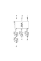
- the controller 100 has an acceleration control unit 111, a current control unit 112, an instantaneous state observer 113, a compensation unit 114, and the like as a functional configuration (hereinafter, referred to as “functional block”). It has a current detection unit 119.
- the acceleration control unit 111 brings the driving torque (driving force) of the second inertial body 92 closer to the torque target value (control target) whose target acceleration is the acceleration a L of the second inertial body 92.
- the calculation of the target value of the drive torque of is repeatedly executed in a predetermined control cycle.
- the current control unit 112 (control unit) outputs a current for setting the drive torque of the first inertial body 91 to the torque target value to the armature 62 each time the acceleration control unit 111 calculates a torque target value.
- the current detection unit 119 detects the current output by the current control unit 112 to the armature 62.
- the instantaneous state observer 113 estimates the state of the controlled object based on the physical quantity that correlates with the acceleration of the second inertial body 92.
- the instantaneous state observer 113 has a second inertial body 92 based on the values detected by the acceleration sensors 51, 52, 53, 54, 55, 56, the speed sensor 70, and the current detection unit 119. Estimate the speed and deflection angle of.
- the compensation unit 114 calculates a compensation component that cancels the feedback component that occurs in the control target and affects the operation of the second inertial body 92 based on the operation state of the control target, and the current control unit 112 outputs the drive to the armature 62. Add to power.
- the compensation unit 114 includes a first compensation component that cancels the feedback component input from the transmission element 83 to the first inertial body 91, and a second compensation component that cancels the feedback component input from the second inertial body 92 to the transmission element 83. May be calculated based on the operating state of the controlled object and added to the drive power output by the current control unit 112 to the armature 62. For example, the compensation unit 114 calculates the first compensation component so as to cancel the feedback component FB01 which is the reaction force input from the transmission element 83 to the first inertial body 91, and inputs the first compensation component from the second inertial body 92 to the transmission element 83. The second compensation component is calculated so as to cancel the feedback component FB02, which is the operating speed of the second inertial body 92.
- the compensating unit 114 provides a third compensating component that cancels the feedback component FB03, which is a viscous resistance generated in the first inertial body 91, and a fourth compensating component that cancels the feedback component FB04, which is a viscous resistance generated in the second inertial body 92. It may be further added to the drive power output by the current control unit 112 to the armature 62.
- the compensation unit 114 may calculate the first compensation component and the second compensation component based on the detection values of the simultaneous points of the physical quantities that correlate with the acceleration of the second inertial body 92. Further, the compensation unit 114 may calculate the first compensation component, the second compensation component, the third compensation component, and the fourth compensation component based on the detection values of the simultaneous points of the physical quantities.
- the compensation unit 114 may calculate at least one of the first compensation component and the second compensation component by the instantaneous state observer 113.
- the compensation unit 114 has the acceleration detected by the acceleration sensors 51, 52, 53, 54, 55, 56, the operating speed of the first inertial body 91 detected by the speed sensor 70, and the current detection unit 119 in each control cycle.
- the first compensation component, the second compensation component, the third compensation component, and the fourth compensation component are calculated based on the operating state of the controlled object estimated by the instantaneous state observer 113 based on the current detected by.
- Control procedure Subsequently, as an example of the control method, the control procedure executed by the controller 100 will be specifically illustrated.
- This control procedure outputs the driving power for making the driving force of the second inertial body 92 follow the control target to the armature 62, and affects the operation of the second inertial body 92 generated in the controlled object.
- the first compensation component and the second compensation component may be calculated based on the operating state of the controlled object and added to the drive power output to the armature 62.
- the first compensation component may be calculated so as to cancel the feedback component FB01
- the second compensation component may be calculated so as to cancel the feedback component FB02.
- the first compensation component and the second compensation component may be calculated based on the detected values of the simultaneous points of the physical quantities that correlate with the acceleration of the second inertial body 92. At least one of the first compensating component and the second compensating component may be calculated by the instantaneous state observer 113.
- This control procedure includes a state estimation procedure by the instantaneous state observer 113, a calculation procedure of the torque target value of the first inertial body 91 by the acceleration control unit 111, a drive power output procedure by the current control unit 112, and a compensation unit 114. Includes the procedure for adding compensation components. Hereinafter, each procedure will be illustrated in detail.
- the acceleration a L of the second inertial body 92 is detected by the acceleration sensors 51, 52, 53, 54, 55, 56 with a delay indicated by the transfer function TF 22, and the acceleration detection value a L_sens, which is the detection result, is instantaneous. Further input to the state observer 113.
- the velocity ⁇ M of the first inertial body 91 is detected by the velocity sensor 70 with a delay indicated by the transfer function TF23, and the velocity detection value ⁇ M_sensor, which is the detection result, is further input to the instantaneous state observer 113.
- Instantaneous state observer 113 the current detection value I Q_sens, based on the detected acceleration value a L_sens and speed detection value omega M_sens, velocity estimates of the second inertial body 92 ⁇ L_ob, velocity estimation value of the first inertia body 91 ⁇ M_ob , And the estimated deflection angle ⁇ s_ob of the transmission element 83 is calculated.
- the speed estimation value ⁇ M_ob is the same as the speed detection value ⁇ M_sens .
- the acceleration control unit 111 has a torque target value TL_ref , which is a target value of the drive torque (torque TL ) of the second inertial body 92, and a feedback value of the drive torque of the second inertial body 92.
- the torque feedback value TL_fb is calculated, and these deviations (hereinafter, referred to as “torque deviation”) are calculated.
- the acceleration control unit 111 calculates the torque target value TL_ref by multiplying the acceleration target value a L_ref by the inertia model value J Ln .
- the inertia model value J Ln is an inertia model value of the second inertial body 92, and is held by the controller 100.
- the acceleration control unit 111 calculates the torque feedback value TL_fb by multiplying the acceleration detection value a L_sens of the second inertial body 92 by the inertia model value J Ln . As indicated by the summing point AP 31, the acceleration control unit 111 subtracts the torque feedback value T L_fb from the torque target value T L_ref calculates the torque deviation.
- the acceleration control unit 111 calculates the difference velocity target value ⁇ s_ref which is the target value of the difference velocity ⁇ s input to the transmission element 83 and the difference velocity feedback value ⁇ s_fb which is the feedback value of the difference velocity ⁇ s. , These deviations (hereinafter referred to as "difference velocity deviation") are calculated.
- difference velocity deviation the difference between the speed target value omega s_ref by multiplying the reciprocal of the acceleration gain g a and spring constant model values K sn in the torque deviation.
- Acceleration gain g a is a constant set in advance
- the spring constant model value K sn is the model value of the spring constant K s transmission element 83, both the controller 100 holds.
- the acceleration control unit 111 calculates the ideal speed ⁇ L_id by multiplying the speed detection value ⁇ M_sens of the first inertial body 91 by the reduction ratio model value R gn .
- the reduction ratio model value R gn is a model value of the reduction ratio of the transmission element 83, and is held by the controller 100.
- the ideal velocity ⁇ L_id is the velocity ⁇ L when the difference velocity ⁇ s is zero.
- the acceleration control unit 111 calculates the differential velocity feedback value ⁇ s_fb by subtracting the ideal velocity ⁇ L_id from the velocity estimated value ⁇ L_ob of the second inertial body 92.
- the acceleration control unit 111 calculates the difference velocity deviation by subtracting the difference velocity feedback value ⁇ s_fb from the difference velocity target value ⁇ s_ref .
- the acceleration control unit 111 calculates the torque target value TM_ref , which is the target value of the drive torque of the first inertial body 91, based on the difference velocity deviation. For example an acceleration control unit 111, the transfer function TF37, multiplied by the speed difference gain g v a difference speed deviation as indicated by TF38 calculates the target acceleration a M_Ref, the inertia model acceleration target value a M_Ref value J Mn And the reduction ratio model value R gn are multiplied to calculate the torque target value TM_ref .
- the differential velocity gain g v is a preset constant
- the inertia model value J Mn is an inertia model value of the first inertial body 91, both of which are held by the controller 100. This completes the procedure for calculating the torque target value in one control cycle.
- the current control unit 112 calculates the current target value I q_ref based on the torque target value TM_ref , and outputs the current I q corresponding to the current target value I q_ref to the armature 62. For example, as shown by transfer function TF41, current control unit 112 calculates a current target value I Q_ref by multiplying the reciprocal of the torque constant model value K tn the torque target value T M_Ref. Torque constant model value K tn is a model value of the torque constant K T, the controller 100 holds.
- the current control unit 112 to the current target value I Q_ref, calculates a current I q according to the current target value I Q_ref with a delay represented by a transfer function TF42, and outputs to the armature 62.
- the compensation unit 114 adds the acceleration detection value a L_sens to the acceleration target value a M_ref .
- the acceleration detection value a L_sens added here becomes the second compensation component via the transfer functions TF38, TF41, and TF42.
- the compensation unit 114 calculates the second compensation component and adds it to the current I q .
- the second compensation component becomes a value corresponding to the difference velocity ⁇ s through the transfer functions TF01, TF02, TF03, and TF04, and cancels the feedback component FB02.
- the addition point of the acceleration detection value a L_sens is not necessarily limited to the addition point AP34.
- the compensation unit 114 may add a value obtained by multiplying the acceleration detection value a L_sens by the inertia model value J Mn and the reduction ratio model value R gn to the torque target value TM_ref .
- Viscosity coefficient model value D Ln is a model value of the viscosity coefficient D L, the controller 100 holds.
- the viscous resistance added here becomes the fourth compensation component via the transfer functions TF33, TF34, TF37, TF38, TF41, and TF42.
- the compensation unit 114 calculates the fourth compensation component and adds it to the current Iq .
- the fourth compensation component becomes a value corresponding to the viscous resistance of the second inertial body 92 through the transfer functions TF01, TF02, TF03, TF04, TF05, and TF06, and cancels the feedback component FB04.
- compensator 114 may be added to the difference speed target value omega s_ref by multiplying the reciprocal of the acceleration gain g a and spring constant model values K sn in viscous resistance.
- the compensation unit 114 multiplies the estimated deflection angle value ⁇ s_ob by the spring constant model value K sn , and further multiplies this by the reciprocal of the reduction ratio model value R gn. To calculate the estimated torque value T s_ob .
- the torque estimated value T s_ob is an estimated value of the torque T s transmitted from the transmission element 83 to the second inertial body 92.
- the compensation unit 114 adds the torque estimation value T s_ob to the torque target value TM_ref .
- the torque estimated value T s_ob added here becomes the first compensation component via the transfer functions TF41 and TF42.
- the compensation unit 114 calculates the first compensation component and adds it to the current Iq .
- the first compensation component becomes a value corresponding to the torque T s through the transfer function TF01, and cancels the feedback component FB01.
- the addition point of the torque estimated value T s_ob is not necessarily limited to the addition point AP35.
- compensator 114 it may be added to the current target value I Q_ref by multiplying the reciprocal of the torque constant model value K tn the torque estimate T s_ob.
- the compensation unit 114 multiplies the velocity detection value ⁇ M_sens by the viscosity coefficient model value D Mn to calculate the viscosity resistance generated in the first inertial body 91, and adds this to the summing point AP35. Add to the torque target value TM_ref .
- Viscosity coefficient model value D Mn is the model value of the viscosity coefficient D M, the controller 100 holds.
- the viscous resistance added here becomes the third compensation component via the transfer functions TF41 and TF42.
- the compensation unit 114 calculates the third compensation component and adds it to the current Iq .
- the third compensating component becomes a value corresponding to the viscous resistance of the first inertial body 91 via the transfer function TF01, and cancels the feedback component FB03.
- the point where the viscous resistance is added is not necessarily limited to the addition point AP35.
- the compensator 114 may multiply the viscous resistance by the reciprocal of the torque constant model value K tn and add it to the current target value I q_ref .
- FIG. 9 is a block diagram illustrating the hardware configuration of the controller 100.
- the controller 100 has a circuit 120.
- the circuit 120 includes one or more processors 121, a memory 122, a storage 123, a driver 124, and an input / output port 125.
- the storage 123 has a computer-readable storage medium, such as a non-volatile semiconductor memory.
- the storage 123 outputs the driving power for making the driving force of the second inertial body 92 follow the control target to the armature 62, and generates driving power in the controlled object (for example, the robot 10) of the second inertial body 92.
- a program for causing the controller 100 to execute the calculation of the compensation component that cancels the feedback component that affects the operation based on the operating state of the controlled object and adding it to the drive power output to the armature 62 is stored.
- the storage 123 stores a program for configuring the functional block of the controller 100 described above.
- the memory 122 temporarily stores the program loaded from the storage medium of the storage 123 and the calculation result by the processor 121.
- the processor 121 constitutes each functional block of the controller 100 by executing the above program in cooperation with the memory 122.
- the driver 124 drives the motor 60 according to a command from the processor 121.
- the input / output port 125 inputs / outputs an electric signal to / from the speed sensor 70 and the acceleration sensors 51, 52, 53, 54, 55, 56 in accordance with a command from the processor 121.
- the circuit 120 is not necessarily limited to the one in which each function is configured by a program.
- the circuit 120 may have at least a part of its functions configured by a dedicated logic circuit or an ASIC (Application Specific Integrated Circuit) that integrates the logic circuit.
- ASIC Application Specific Integrated Circuit
- the controller 101 shown in FIG. 10 controls the operating speed of the second inertial body 92 by using a configuration in which the driving force of the second inertial body 92 follows the control target.
- the controller 101 is the controller 100 described above with the speed control unit 115 added.
- the speed control unit 115 has a deviation between the speed target value ⁇ L_ref , which is the target value of the speed ⁇ L of the second inertial body 92, and the speed estimation value ⁇ L_ob (hereinafter referred to as “speed deviation”).
- the acceleration target value a L_ref corresponding to) is calculated and output to the acceleration control unit 111.
- the speed control unit 115 calculates the speed deviation by subtracting the speed estimation value ⁇ L_ob from the speed target value ⁇ L_ref .
- speed control unit 115 calculates the target acceleration a L_ref by multiplying the speed gain g vp the speed deviation.
- the speed gain g bp is a preset constant and is held by the controller 100. This completes the procedure for calculating the acceleration target value a L_ref by the speed control unit 115.
- the control for causing the acceleration a L to follow the acceleration target value a L_ref is the same as that for the controller 100.
- the controller 102 shown in FIG. 12 controls the position of the second inertial body 92 by utilizing the configuration in which the driving force of the second inertial body 92 follows the control target.
- the controller 102 is a controller 101 described above with a position control unit 116 added.
- the position control unit 116 has a deviation between the position target value ⁇ L_ref , which is the target value of the position ⁇ L of the second inertial body 92, and the position estimated value ⁇ L_ob (hereinafter, referred to as “position deviation”).
- the speed target value ⁇ L_ref corresponding to) is calculated and output to the speed control unit 115.
- the position control unit 116 subtracts the position estimated value ⁇ L_ob of the second inertial body 92 from the position target value ⁇ L_ref (angle target value) of the second inertial body 92 to position the position. Calculate the deviation.
- the position estimated value ⁇ L_ob is calculated by, for example, integrating the velocity estimated value ⁇ L_ob .
- the position control unit 116 calculates the velocity target value ⁇ L_ref by multiplying the position deviation by the position gain g pp .
- the position gain g pp is a preset constant and is held by the controller 100. This completes the procedure for calculating the speed target value ⁇ L_ref by the position control unit 116.
- the control for making the speed ⁇ L follow the speed target value ⁇ L_ref is the same as that of the controller 101.
- the controller 103 shown in FIG. 14 controls the force applied to the external environment by the second inertial body 92 by utilizing the configuration in which the driving force of the second inertial body 92 follows the control target.
- the controller 103 replaces the acceleration control unit 111 of the controller 100 described above with the force control unit 117.
- Force control unit 117 so as to approach the external torque T e of imparting the second inertial body 92 to the outside environment to the torque target value (control target), calculates the target value of the driving torque of the first inertia body 91 This is repeatedly executed in a predetermined control cycle.
- FIG. 15 is a block diagram showing the external environment as a model in addition to the first inertial body 91, the transmission element 83, and the second inertial body 92.
- the external environment is modeled as having elasticity and viscosity. That is, in FIG. 15, elastic rebound force and viscous resistance act on the second inertial body 92 from the external environment.
- the elastic repulsive force of the magnitude obtained by multiplying the spring constant K E of the external environment to the displacement angle obtained by integrating the speed omega L occurs.
- the transfer function TF73 a viscous resistance having a magnitude obtained by multiplying the velocity ⁇ L by the viscous component DE of the external environment is generated.
- the elastic repulsive force and the viscous resistance and is summed external torque T e is transmitted to the second inertial body 92. Therefore, as shown by the summing point AP01 addition, the second inertial body 92, transmitted torque T L obtained by subtracting the external torque T e from the torque T s.
- the force control unit 117 calculates the torque feedback value T E_fb a feedback value of the force which the second inertia member 92 is given to the external environment (the external torque T e), the external torque T e the deviation between the torque target value T E_REF and the torque feedback value T E_fb a target value (hereinafter, referred to as "torque deviation”.) is calculated.
- the force control unit 117 adds up the torque detection value T E_sens a detection value of the external torque T e, and the torque feedback value T L_fb corresponding to the acceleration a L
- the torque feedback value Te_fb is calculated.
- the force control unit 117 subtracts the torque feedback value T E_fb from the torque target value T E_REF calculates the torque deviation.
- the control procedure for reducing the torque deviation is the same as that of the controller 100.
- the compensation unit 114 adds the viscosity resistance calculated by multiplying the velocity estimation value ⁇ L_ob by the viscosity coefficient model value D Ln , and adds it to the torque target value Te_ref at the summing point AP65.
- the controller 104 shown in FIG. 17 uses a configuration in which the driving force of the second inertial body 92 follows the control target, and the position of the second inertial body 92 and the second inertial body 92 apply to the external environment. Perform hybrid control with force.
- the controller 104 replaces the acceleration control unit 111 of the controller 100 described above with the hybrid control unit 118.
- the hybrid control unit 118 calculates the target value of the drive torque of the first inertial body 91 so that both the position of the second inertial body 92 and the force applied to the external environment by the second inertial body 92 come close to the control target. This is repeatedly executed in a predetermined control cycle.
- FIG. 18 is a block diagram illustrating a procedure for calculating a torque target value of the first inertial body 91 executed by the hybrid control unit 118.
- the robot 10 is driven by any of the actuators 41, 42, 43, 44, 45, 46 instead of having an acceleration sensor for each actuator 41, 42, 43, 44, 45, 46.
- An acceleration sensor may be provided at the tip portion 16.
- FIG. 18 illustrates a case where the actuators 41, 42, 43, 44, 45, 46 are controlled based on the acceleration sensor 57 and the force sensor 90 at the tip portion 16.
- the position, velocity, acceleration, force, and the like of the tip portion 16 all include six components, a translation component along the three orthogonal axes and a rotation component around the three orthogonal axes.
- the hybrid control unit 118 calculates the position feedback value P t_fb , which is the feedback value of the position of the tip portion 16, and the deviation between the position target value P t_ref of the tip portion 16 and the position feedback value P t_fb.
- the speed target value V t_ref of the tip portion 16 is calculated according to the above.
- the hybrid control unit 118 integrates the velocity estimates ⁇ L_ob of the joints 31, 32, 33, 34, 35, 36 as shown by the transfer functions TF81 and TF82, and performs a forward kinematics calculation on the integrated result.
- the position feedback value P t_fb is calculated.
- the hybrid control unit 118 subtracts the position feedback value P t_fb from the position target value P t_ref to calculate the deviation (hereinafter, referred to as “position deviation”).
- position deviation As shown by the transfer function TF83, the hybrid control unit 118 calculates the velocity target value V t_ref by multiplying the position deviation by the position gain g pp .
- the position gain g pp is a preset constant and is held by the controller 100.
- the hybrid control unit 118 calculates the speed feedback value V t_fb , which is the speed feedback value of the tip portion 16, and the tip portion 16 according to the deviation between the speed target value V t_ref of the tip portion 16 and the speed feedback value V t_fb .
- the acceleration target value at_ref is calculated.
- the hybrid control unit 118 multiplies the speed estimation value ⁇ L_ob of the joints 31, 32, 33, 34, 35, 36 by a predetermined transformation matrix J and speed feedback of the tip portion 16 as shown by the transfer function TF84. Calculate the value V t_fb .
- the hybrid control unit 118 calculates the deviation (hereinafter, referred to as “speed deviation”) by subtracting the speed feedback value V t_fb from the speed target value V t_ref as indicated by the addition point AP82.
- speed deviation the target acceleration a T_ref by multiplying the speed gain g vp the speed deviation.
- the speed gain g bp is a preset constant and is held by the controller 100.
- the hybrid control unit 118 sets the torque target value TL_ref , which is the target value of the drive torque for controlling the position of the second inertial body 92, to the actuators 41, 42, 43, based on the acceleration target value at_ref . Calculated every 44, 45, 46.
- the hybrid control unit 118 multiplies the acceleration target value at_ref by the inverse transformation matrix J -1, and the acceleration target value a for each actuator 41, 42, 43, 44, 45 , 46. Calculate L_ref .
- the hybrid control unit 118 may further multiply the acceleration target value at_ref by the selection matrix S.
- the selection matrix S is a matrix for extracting components in the control direction of the position of the second inertial body 92, and is held by the controller 100.
- the hybrid control unit 118 calculates the torque target value TL_ref by multiplying the acceleration target value a L_ref by the inertia model value J Ln , as shown by the transfer function TF87.
- the hybrid control unit 118 calculates a torque target value Te_ref for controlling the force applied to the external environment by the second inertial body 92.
- the transfer function as indicated by the TF88, tip 16 is multiplied by the transformation matrix J T to the force target value F T_ref is a target value of the force applied to the external environment actuator 41,
- the torque target value Te_ref for each of 43, 44, 45, and 46 is calculated.
- the hybrid control unit 118 may further multiply the force target value F t_ref by the selection matrix IS .
- the selection matrix IS is a matrix for extracting the components in the control direction of the force applied to the external environment by the second inertial body 92, and is held by the controller 100.
- the torque target value T L_ref for controlling the position of the second inertial body 92 after the second inertial body 92 has calculated the torque target value T E_REF for controlling the force applied to the external environment ,
- the hybrid control unit 118 sums these together as shown by the addition point AP83 to calculate the torque target value T s_ref .
- the torque target value T s_ref is a target value of the torque transmitted from the transmission element 83 to the second inertial body 92.
- the hybrid control unit 118 calculates a torque feedback value T s_fb , which is a torque feedback value transmitted from the transmission element 83 to the second inertial body 92, and deviates from the torque target value T s_ref and the torque feedback value T s_fb (hereinafter, "Torque deviation”) is calculated.
- the hybrid control unit 118 multiplies the acceleration detection value at_sens of the tip portion 16 by the inverse transformation matrix J -1 , and further multiplies this by the inertia model value J Ln.
- the torque feedback value TL_fb is calculated.
- the hybrid control unit 118 multiplies the force detection value F t_sens , which is the detection value of the force applied to the external environment by the tip portion 16, by the transformation matrix J T , and the torque feedback value T. Calculate e_fb .
- the hybrid control unit 118 may further multiply the force detection value F t_sens by the selection matrix IS described above.
- hybrid control unit 118 calculates the torque feedback value T S_fb by summing the torque feedback value T L_fb and the torque feedback value T e_fb.
- the hybrid control unit 118 calculates the torque deviation by subtracting the torque feedback value T s_fb from the torque target value T s_ref as shown by the addition point AP85.
- the control procedure for reducing the torque deviation is the same as that of the controller 100.
- the compensation unit 114 adds the viscosity resistance calculated by multiplying the velocity estimation value ⁇ L_ob by the viscosity coefficient model value D Ln , and adds it to the torque target value T s_ref at the summing point AP85.
- the controller 100 is composed of the first inertial body 91, the armature 62 that drives the first inertial body 91 in response to the supply of electric power, the second inertial body 92, and the first inertial body 91.
- a current control unit 112 that outputs driving power for making the driving force of the second inertial body 92 follow a control target to a controlled armature 62 having a transmission element 83 that transmits power to the second inertial body 92.
- the compensation component that cancels the feedback component that occurs in the controlled object and affects the operation of the second inertial body 92 is calculated based on the operating state of the controlled object, and added to the drive power output by the current control unit 112 to the armature 62. Compensation unit 114 and
- the behavior of the first inertial body 91 and the second inertial body 92 can be brought closer to one delay element.
- the vibration generated between the first inertial body 91 and the second inertial body 92 is suppressed, so that the followability of the driving force of the second inertial body 92 with respect to the control target is improved. Therefore, it is effective in improving the stability of control.
- the compensation unit 114 includes a first compensation component that cancels the feedback component input from the transmission element 83 to the first inertial body 91, and a second compensation component that cancels the feedback component input from the second inertial body 92 to the transmission element 83. May be calculated based on the operating state of the controlled object and added to the drive power output by the current control unit 112 to the armature 62. In this case, the vibration generated between the first inertial body 91 and the second inertial body 92 is more reliably suppressed.
- the compensation unit 114 calculates the first compensation component so as to cancel the reaction force input from the transmission element 83 to the first inertial body 91, and the second inertial body 92 input from the second inertial body 92 to the transmission element 83.
- the second compensating component may be calculated so as to cancel the operating speed of.
- the compensation unit 114 may calculate the first compensation component and the second compensation component based on the detection values of the simultaneous points of the physical quantities that correlate with the acceleration of the second inertial body 92. In this case, the phase shift of the first compensation component and the second compensation component is suppressed. Therefore, the vibration generated between the first inertial body 91 and the second inertial body 92 is more reliably suppressed.
- the compensation unit 114 may calculate at least one of the first compensation component and the second compensation component by the instantaneous state observer 113. In this case, the first compensating component and the second compensating component can be easily derived.
- the present disclosure is not necessarily limited to the above-described embodiments, and various changes can be made without departing from the gist thereof.
- a robot system in which a robot is a controlled object is illustrated, but the present invention is not limited to this.
- the control device of the present disclosure transmits power from the first inertial body, the armature that drives the first inertial body in response to the supply of electric power, the second inertial body, and the first inertial body to the second inertial body. It is effective in improving the followability of the driving force of the second inertial body in the control of any controlled object having a transmission element.
Landscapes
- Engineering & Computer Science (AREA)
- Robotics (AREA)
- Mechanical Engineering (AREA)
- Power Engineering (AREA)
- Manipulator (AREA)
- Control Of Electric Motors In General (AREA)
Abstract
コントローラ100は、第1慣性体91と、電力の供給に応じて第1慣性体91を駆動する電機子62と、第2慣性体92と、第1慣性体91から第2慣性体92に動力を伝達する伝達要素83とを有する制御対象の電機子62に対し、第2慣性体92の駆動力を制御目標に追従させるための駆動電力を出力する電流制御部112と、制御対象内で生じ第2慣性体92の動作に影響するフィードバック成分を打ち消す補償成分を制御対象の動作状態に基づいて算出し、電流制御部112が電機子62に出力する駆動電力に加算する補償部114と、を備える。
Description
本開示は、制御装置、制御方法及びロボットシステムに関する。
特許文献1には、外乱オブザーバによりモータへの外乱トルクを推定し、外乱トルクを補償してモータを制御するモータ制御装置が開示されている。
本開示は、制御の安定性向上に有効な制御装置、制御方法及びロボットシステムを提供する。
本開示の一側面に係る制御装置は、第1慣性体と、電力の供給に応じて第1慣性体を駆動する電機子と、第2慣性体と、第1慣性体から第2慣性体に動力を伝達する伝達要素とを有する制御対象の電機子に対し、第2慣性体の駆動力を制御目標に追従させるための駆動電力を出力する制御部と、制御対象内で生じ第2慣性体の動作に影響するフィードバック成分を打ち消す補償成分を制御対象の動作状態に基づいて算出し、制御部が電機子に出力する駆動電力に加算する補償部と、を備える。
本開示の他の側面に係る制御方法は、第1慣性体と、電力の供給に応じて第1慣性体を駆動する電機子と、第2慣性体と、第1慣性体から第2慣性体に動力を伝達する伝達要素とを有する制御対象の電機子に対し、第2慣性体の駆動力を制御目標に追従させるための駆動電力を出力することと、制御対象内で生じ第2慣性体の動作に影響するフィードバック成分を打ち消す補償成分を制御対象の動作状態に基づいて算出し、電機子に出力する駆動電力に加算することと、を備える。
本開示の更に他の側面に係るロボットシステムは、第1慣性体と、電力の供給に応じて第1慣性体を駆動する電機子と、第2慣性体と、第1慣性体から第2慣性体に動力を伝達する伝達要素とを有するロボットと、第2慣性体の加速度を目標加速度に追従させるための駆動電力を出力する制御部と、ロボット内で生じ第2慣性体の動作に影響するフィードバック成分を打ち消す補償成分をロボットの動作状態に基づいて算出し、制御部が電機子に出力する駆動電力に加算する補償部と、を備える。
本開示によれば、制御の安定性向上に有効な制御装置、制御方法及びロボットシステムを提供することができる。
以下、実施形態について、図面を参照しつつ詳細に説明する。説明において、同一要素又は同一機能を有する要素には同一の符号を付し、重複する説明を省略する。
〔ロボットシステム〕
ロボットシステム1は、ロボットに予め設定された制御目標に従って動作させるシステムである。図1に例示するように、ロボットシステム1は、制御対象の一例であるロボット10と、コントローラ100とを備える。
ロボットシステム1は、ロボットに予め設定された制御目標に従って動作させるシステムである。図1に例示するように、ロボットシステム1は、制御対象の一例であるロボット10と、コントローラ100とを備える。
(ロボット)
ロボット10は、例えば6軸の垂直多関節ロボットであり、基部11と、旋回部12と、第1アーム13と、第2アーム14と、手首部15と、先端部16と、アクチュエータ41,42,43,44,45,46と、加速度センサ51,52,53,54,55,56とを有する。
ロボット10は、例えば6軸の垂直多関節ロボットであり、基部11と、旋回部12と、第1アーム13と、第2アーム14と、手首部15と、先端部16と、アクチュエータ41,42,43,44,45,46と、加速度センサ51,52,53,54,55,56とを有する。
基部11は、床面又は台車等に固定される。旋回部12は基部11上に設けられており、鉛直な軸線21まわりに旋回可能である。すなわちロボット10は、軸線21まわりに旋回部12を旋回可能とする関節31を有する。
第1アーム13は、旋回部12から延出しており、軸線21に交差(例えば直交)する軸線22まわりに揺動可能である。すなわちロボット10は、軸線22まわりに第1アーム13を揺動可能とする関節32を有する。なお、ここでの交差は、所謂立体交差のように互いにねじれの関係にある状態での交差を含む。以下においても同様である。
第2アーム14は、第1アーム13の先端部から延出しており、軸線21に交差(例えば直交)する軸線23まわりに揺動可能である。すなわちロボット10は、軸線23まわりに第2アーム14を揺動可能とする関節33を有する。軸線23は軸線22と平行であってもよい。
第2アーム14の先端部は、第2アーム14の延出方向に沿って軸線23に交差(例えば直交)する軸線24まわりに旋回可能である。すなわちロボット10は、軸線24まわりに第2アーム14の先端部を旋回可能とする関節34を有する。
手首部15は、第2アーム14の先端部から延出しており、軸線24に交差(例えば直交)する軸線25まわりに揺動可能である。すなわちロボット10は、軸線25まわりに手首部15を揺動可能とする関節35を有する。
先端部16は、手首部15の先端部に設けられており、手首部15の延出方向に沿って軸線25に交差(例えば直交)する軸線26まわりに旋回可能である。すなわちロボット10は、軸線26まわりに先端部16を旋回可能とする関節36を有する。先端部16には、作業用の様々なツールが設けられる。ツールの具体例としては、ワークを保持するためのハンド、塗料を吐出する塗装ガン、及び溶接トーチ等が挙げられる。
アクチュエータ41,42,43,44,45,46は、関節31,32,33,34,35,36をそれぞれ駆動する。例えばアクチュエータ41は軸線21まわりに旋回部12を旋回させ、アクチュエータ42は軸線22まわりに第1アーム13を揺動させ、アクチュエータ43は軸線23まわりに第2アーム14を揺動させ、アクチュエータ44は軸線24まわりに第2アーム14の先端部を旋回させ、アクチュエータ45は軸線25まわりに手首部15を揺動させ、アクチュエータ46は軸線26まわりに先端部16を旋回させる。
加速度センサ51,52,53,54,55,56のそれぞれは、駆動対象部分に取り付けられている。加速度センサ51,52,53,54,55,56は、アクチュエータ41,42,43,44,45,46による駆動対象部分(以下、単に「駆動対象部分」という。)の加速度をそれぞれ検出する。
なお、加速度センサ51,52,53,54,55,56は、加速度に相関する何らかの物理量を検出するセンサであればよく、ロボット10は、必ずしも加速度自体を検出するセンサを有していなくてよい。例えば加速度センサ51,52,53,54,55,56は、アクチュエータ41,42,43,44,45,46の駆動対象の駆動力をそれぞれ検出する力センサ(例えばトルクセンサ)であってもよい。
また、ロボット10は、アクチュエータ41,42,43,44,45,46ごとに加速度センサを有するのに代えて、アクチュエータ41,42,43,44,45,46のいずれによっても駆動される先端部16に加速度センサを有していてもよい。例えばロボット10は、先端部16に6軸(並進3軸及び回転3軸)の加速度センサを有していてもよい。
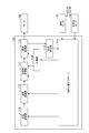
図2に示すように、アクチュエータ41,42,43,44,45,46のそれぞれは、モータ60と、速度センサ70と、減速機80とを有する。モータ60は、ロータ61と、電力の供給に応じてロータ61を回転駆動する電機子62とを有する。速度センサ70は、ロータ61の回転速度を検出する。速度センサ70の具体例としては、ロータリーエンコーダ等のパルスジェネレータ、及びタコジェネレータ等が挙げられる。
減速機80は、ロータ61に接続される入力軸81と、駆動対象部分に接続される出力軸82と、入力軸81から出力軸82に駆動力を伝達する伝達要素83とを有する。伝達要素83は、例えば少なくとも一つのギヤにより構成されており、入力軸81の回転速度に所定の減速比を乗算して出力軸82に伝達し、入力軸81の回転トルクに上記減速比の逆数を乗算して出力軸82に伝達する。
ロータ61と駆動対象部分との間には、伝達要素83の変形等に起因する撓みが生じる。そこで、アクチュエータ41,42,43,44,45,46及びその駆動対象部分は、ロータ61を主体とする第1慣性体91と、電力の供給に応じて第1慣性体91を駆動する電機子62と、駆動対象部分を主体とする第2慣性体92と、第1慣性体91から第2慣性体92に力を伝達する伝達要素83とによって近似可能である。
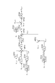
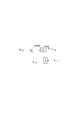
このように近似されたモデルにおいては、図3の伝達関数TF01で示されるように、電機子62からの電流Iqに所定のトルク定数KTを乗算した大きさの駆動力(例えばトルクTM)が第1慣性体91に生じる。これに応じ、第1慣性体91は、伝達関数TF02で示されるように、トルクTMを第1慣性体91のイナーシャJMで除算した大きさの加速度aMで加速される。更に、伝達関数TF03で示されるように、加速度aMが積分されて第1慣性体91が速度ωMで動作する。
第1慣性体91の速度ωMは、伝達関数TF04で示されるように、減速比Rgで除算された大きさの速度ωMtとして第2慣性体92側に伝わる。第1慣性体91から第2慣性体92側に伝わる速度ωMtと、第2慣性体92の速度ωLとの間に差(以下、この差を「差速度ωs」という。)が生じると、伝達関数TF05で示されるように差速度ωsが積分されて撓み角θsが生じる。更に、伝達関数TF06で示されるように、撓み角θsに所定のばね定数Ksを乗算した大きさの駆動力(例えばトルクTs)が第2慣性体92に伝わる。
また、第2慣性体92には、外乱のトルクTdisも伝わる。このため、加え合わせ点AP01で示されるように、第2慣性体92には、トルクTsからトルクTdisを減算したトルクTLが伝わる。
これに応じ、第2慣性体92は、伝達関数TF07で示されるように、トルクTLを第2慣性体92のイナーシャJLで除算した大きさの加速度aLで加速される。更に、伝達関数TF08で示されるように、加速度aLが積分されて第2慣性体92が速度ωLで動作する。
上述した第1慣性体91から第2慣性体92への力、加速度及び速度の伝達成分に加えて、第1慣性体91と第2慣性体92との間には複数のフィードバック成分が生じる。例えば、伝達関数TF09で示されるように、上記トルクTsを減速比Rgで除算した大きさのトルクTstが反力として伝達要素83から第1慣性体91に伝わる。このため、加え合わせ点AP02で示されるように、第1慣性体91には、トルクTMからトルクTstを減算したトルクTRが伝わる。また、第2慣性体92の速度ωLが、上記差速度ωsを定める速度成分として第2慣性体92から伝達要素83に伝わる。
更に、第1慣性体91の速度ωMに比例する粘性抵抗が第1慣性体91に生じ、第2慣性体92の速度ωLに比例する粘性抵抗が第2慣性体92に生じる。具体的には、伝達関数TF11で示されるように、速度ωMに粘性係数DMを乗算した大きさのトルクTdmが第1慣性体91に作用する。このため、加え合わせ点AP02で示されるように、上記トルクTRは、トルクTMからトルクTstを減算し、更にトルクTdmを減算した値となる。
また、伝達関数TF12で示されるように、速度ωLに粘性係数DLを乗算した大きさのトルクTdlが第2慣性体92に作用する。このため、加え合わせ点AP01で示されるように、第2慣性体92には、トルクTsからトルクTdisを減算し、更にトルクTdlを減算したトルクTLが伝わる。
このように、第1慣性体91と第2慣性体92との間に生じるフィードバック成分の具体例としては、伝達要素83から第1慣性体91に入力される反力であるフィードバック成分FB01と、第2慣性体92から伝達要素83に入力される第2慣性体92の動作速度であるフィードバック成分FB02と、第1慣性体91に生じる粘性抵抗であるフィードバック成分FB03と、第2慣性体92に生じる粘性抵抗であるフィードバック成分FB04とが挙げられる。
コントローラ100(制御装置)は、電機子62に対し、第2慣性体92の駆動力を制御目標に追従させるための駆動電力を出力することと、制御対象(例えばロボット10)内で生じ第2慣性体92の動作に影響するフィードバック成分を打ち消す補償成分を制御対象の動作状態に基づいて算出し、電機子に出力する駆動電力に加算することと、を実行するように構成されている。
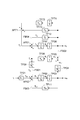
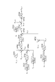
図4は、コントローラ100の少なくとも一部と機能的に等価な構成を示す図である。図4に示すように、コントローラ100は、機能上の構成(以下、「機能ブロック」という。)として、加速度制御部111と、電流制御部112と、瞬時状態オブザーバ113と、補償部114と、電流検出部119とを有する。
加速度制御部111は、第2慣性体92の加速度aLを目標加速度とするトルク目標値(制御目標)に第2慣性体92の駆動トルク(駆動力)を近付けるように、第1慣性体91の駆動トルクの目標値を算出することを所定の制御周期で繰り返し実行する。
電流制御部112(制御部)は、加速度制御部111がトルク目標値を算出する度に、第1慣性体91の駆動トルクを当該トルク目標値とするための電流を電機子62に出力する。電流検出部119は、電流制御部112が電機子62に出力する電流を検出する。
瞬時状態オブザーバ113は、第2慣性体92の加速度に相関する物理量に基づいて制御対象の状態を推定する。例えば瞬時状態オブザーバ113は、加速度センサ51,52,53,54,55,56による検出値と、速度センサ70による検出値と、電流検出部119による検出値とに基づいて、第2慣性体92の速度及び撓み角等を推定する。
補償部114は、制御対象内で生じ第2慣性体92の動作に影響するフィードバック成分を打ち消す補償成分を制御対象の動作状態に基づいて算出し、電流制御部112が電機子62に出力する駆動電力に加算する。
補償部114は、伝達要素83から第1慣性体91に入力されるフィードバック成分を打ち消す第1補償成分と、第2慣性体92から伝達要素83に入力されるフィードバック成分を打ち消す第2補償成分とを制御対象の動作状態に基づいて算出し、電流制御部112が電機子62に出力する駆動電力に加算してもよい。例えば補償部114は、伝達要素83から第1慣性体91に入力される反力である上記フィードバック成分FB01を打ち消すように第1補償成分を算出し、第2慣性体92から伝達要素83に入力される第2慣性体92の動作速度であるフィードバック成分FB02を打ち消すように第2補償成分を算出する。
補償部114は、第1慣性体91に生じる粘性抵抗であるフィードバック成分FB03を打ち消す第3補償成分と、第2慣性体92に生じる粘性抵抗であるフィードバック成分FB04を打ち消す第4補償成分とを、電流制御部112が電機子62に出力する駆動電力に更に加算してもよい。
補償部114は、第2慣性体92の加速度に相関する物理量の同時点の検出値に基づいて第1補償成分及び第2補償成分を算出してもよい。また、補償部114は、上記物理量の同時点の検出値に基づいて第1補償成分、第2補償成分、第3補償成分及び第4補償成分を算出してもよい。
補償部114は、第1補償成分及び第2補償成分の少なくとも一方を瞬時状態オブザーバ113により算出してもよい。例えば補償部114は、各制御周期において、加速度センサ51,52,53,54,55,56が検出した加速度と、速度センサ70が検出した第1慣性体91の動作速度と、電流検出部119が検出した電流とに基づき瞬時状態オブザーバ113が推定した制御対象の動作状態に基づいて上記第1補償成分、第2補償成分、第3補償成分及び第4補償成分を算出する。
〔制御手順〕
続いて、制御方法の一例として、コントローラ100が実行する制御手順を具体的に例示する。この制御手順は、電機子62に対し、第2慣性体92の駆動力を制御目標に追従させるための駆動電力を出力することと、制御対象内で生じ第2慣性体92の動作に影響するフィードバック成分を打ち消す補償成分を制御対象の動作状態に基づいて算出し、電機子62に出力する駆動電力に加算することとを含む。
続いて、制御方法の一例として、コントローラ100が実行する制御手順を具体的に例示する。この制御手順は、電機子62に対し、第2慣性体92の駆動力を制御目標に追従させるための駆動電力を出力することと、制御対象内で生じ第2慣性体92の動作に影響するフィードバック成分を打ち消す補償成分を制御対象の動作状態に基づいて算出し、電機子62に出力する駆動電力に加算することとを含む。
上記第1補償成分と、上記第2補償成分とを制御対象の動作状態に基づいて算出し、電機子62に出力する駆動電力に加算してもよい。例えば上記フィードバック成分FB01を打ち消すように第1補償成分を算出し、上記フィードバック成分FB02を打ち消すように第2補償成分を算出してもよい。第2慣性体92の加速度に相関する物理量の同時点の検出値に基づいて第1補償成分及び第2補償成分を算出してもよい。第1補償成分及び第2補償成分の少なくとも一方を瞬時状態オブザーバ113により算出してもよい。
この制御手順は、瞬時状態オブザーバ113による状態推定手順と、加速度制御部111による第1慣性体91のトルク目標値の算出手順と、電流制御部112による駆動電力の出力手順と、補償部114による補償成分の加算手順とを含む。以下、各手順を詳細に例示する。
(状態推定手順)
図5に示すように、電流制御部112が電機子62に出力する電流Iqは、伝達関数TF21で示される遅れをもって電流検出部119により検出され、その検出結果である電流検出値Iq_sensが瞬時状態オブザーバ113に入力される。
図5に示すように、電流制御部112が電機子62に出力する電流Iqは、伝達関数TF21で示される遅れをもって電流検出部119により検出され、その検出結果である電流検出値Iq_sensが瞬時状態オブザーバ113に入力される。
また、第2慣性体92の加速度aLは、伝達関数TF22で示される遅れをもって加速度センサ51,52,53,54,55,56により検出され、その検出結果である加速度検出値aL_sensが瞬時状態オブザーバ113に更に入力される。
第1慣性体91の速度ωMは、伝達関数TF23で示される遅れをもって速度センサ70により検出され、その検出結果である速度検出値ωM_sensが瞬時状態オブザーバ113に更に入力される。
瞬時状態オブザーバ113は、電流検出値Iq_sens、加速度検出値aL_sens及び速度検出値ωM_sensに基づいて、第2慣性体92の速度推定値ωL_ob、第1慣性体91の速度推定値ωM_ob、及び伝達要素83の撓み角推定値θs_obを算出する。なお、速度推定値ωM_obは、速度検出値ωM_sensと同じである。
(トルク目標値の算出手順)
図6に示すように、加速度制御部111は、第2慣性体92の駆動トルク(上記トルクTL)の目標値であるトルク目標値TL_refと、第2慣性体92の駆動トルクのフィードバック値であるトルクフィードバック値TL_fbとを算出し、これらの偏差(以下、「トルク偏差」という。)を算出する。例えば伝達関数TF31で示されるように、加速度制御部111は、加速度目標値aL_refにイナーシャモデル値JLnを乗算してトルク目標値TL_refを算出する。イナーシャモデル値JLnは、第2慣性体92のイナーシャのモデル値であり、コントローラ100が保持している。
図6に示すように、加速度制御部111は、第2慣性体92の駆動トルク(上記トルクTL)の目標値であるトルク目標値TL_refと、第2慣性体92の駆動トルクのフィードバック値であるトルクフィードバック値TL_fbとを算出し、これらの偏差(以下、「トルク偏差」という。)を算出する。例えば伝達関数TF31で示されるように、加速度制御部111は、加速度目標値aL_refにイナーシャモデル値JLnを乗算してトルク目標値TL_refを算出する。イナーシャモデル値JLnは、第2慣性体92のイナーシャのモデル値であり、コントローラ100が保持している。
伝達関数TF32で示されるように、加速度制御部111は、第2慣性体92の加速度検出値aL_sensにイナーシャモデル値JLnを乗算してトルクフィードバック値TL_fbを算出する。加え合わせ点AP31で示されるように、加速度制御部111は、トルク目標値TL_refからトルクフィードバック値TL_fbを減算して上記トルク偏差を算出する。
次に加速度制御部111は、伝達要素83に入力する差速度ωsの目標値である差速度目標値ωs_refと、差速度ωsのフィードバック値である差速度フィードバック値ωs_fbとを算出し、これらの偏差(以下、「差速度偏差」という。)を算出する。例えば伝達関数TF33,TF34で示されるように、加速度制御部111は、加速度ゲインgaとばね定数モデル値Ksnの逆数とをトルク偏差に乗算して差速度目標値ωs_refを算出する。加速度ゲインgaは予め設定された定数であり、ばね定数モデル値Ksnは伝達要素83のばね定数Ksのモデル値であり、いずれもコントローラ100が保持している。
伝達関数TF35で示されるように、加速度制御部111は、第1慣性体91の速度検出値ωM_sensに減速比モデル値Rgnを乗算して理想速度ωL_idを算出する。減速比モデル値Rgnは、伝達要素83の減速比のモデル値であり、コントローラ100が保持している。理想速度ωL_idは、差速度ωsがゼロである場合の速度ωLである。
加え合わせ点AP32で示されるように、加速度制御部111は、第2慣性体92の速度推定値ωL_obから理想速度ωL_idを減算して差速度フィードバック値ωs_fbを算出する。
加え合わせ点AP33で示されるように、加速度制御部111は、差速度目標値ωs_refから差速度フィードバック値ωs_fbを減算して上記差速度偏差を算出する。
次に、加速度制御部111は、差速度偏差に基づいて、第1慣性体91の駆動トルクの目標値であるトルク目標値TM_refを算出する。例えば加速度制御部111は、伝達関数TF37,TF38で示されるように差速度偏差に差速度ゲインgvを乗算して加速度目標値aM_refを算出し、加速度目標値aM_refにイナーシャモデル値JMn及び減速比モデル値Rgnを乗算してトルク目標値TM_refを算出する。差速度ゲインgvは予め設定された定数であり、イナーシャモデル値JMnは第1慣性体91のイナーシャのモデル値であり、いずれもコントローラ100が保持している。以上で、1制御周期におけるトルク目標値の算出手順が完了する。
(駆動電力の出力手順)
図7に示すように、電流制御部112は、トルク目標値TM_refに基づいて電流目標値Iq_refを算出し、電流目標値Iq_refに応じた電流Iqを電機子62に出力する。例えば伝達関数TF41で示されるように、電流制御部112は、トルク定数モデル値Ktnの逆数をトルク目標値TM_refに乗算して電流目標値Iq_refを算出する。トルク定数モデル値Ktnは、上記トルク定数KTのモデル値であり、コントローラ100が保持している。
図7に示すように、電流制御部112は、トルク目標値TM_refに基づいて電流目標値Iq_refを算出し、電流目標値Iq_refに応じた電流Iqを電機子62に出力する。例えば伝達関数TF41で示されるように、電流制御部112は、トルク定数モデル値Ktnの逆数をトルク目標値TM_refに乗算して電流目標値Iq_refを算出する。トルク定数モデル値Ktnは、上記トルク定数KTのモデル値であり、コントローラ100が保持している。
電流制御部112は、電流目標値Iq_refに対し、伝達関数TF42で示される遅れをもって電流目標値Iq_refに従う電流Iqを算出し、電機子62に出力する。
(補償成分の加算手順)
図6において加え合わせ点AP34で示されるように、補償部114は、上記加速度目標値aM_refに加速度検出値aL_sensを加算する。ここで加算された加速度検出値aL_sensは、伝達関数TF38,TF41,TF42を経て上記第2補償成分となる。換言すると、補償部114は上記第2補償成分を算出して電流Iqに加算する。第2補償成分は、伝達関数TF01,TF02,TF03,TF04を経て差速度ωsに相当する値となり、フィードバック成分FB02を打ち消す。
図6において加え合わせ点AP34で示されるように、補償部114は、上記加速度目標値aM_refに加速度検出値aL_sensを加算する。ここで加算された加速度検出値aL_sensは、伝達関数TF38,TF41,TF42を経て上記第2補償成分となる。換言すると、補償部114は上記第2補償成分を算出して電流Iqに加算する。第2補償成分は、伝達関数TF01,TF02,TF03,TF04を経て差速度ωsに相当する値となり、フィードバック成分FB02を打ち消す。
加速度検出値aL_sensの加算箇所は必ずしも加え合わせ点AP34に限られない。例えば補償部114は、加速度検出値aL_sensにイナーシャモデル値JMn及び減速比モデル値Rgnを乗算した値をトルク目標値TM_refに加算してもよい。
伝達関数TF51で示されるように、補償部114は、速度推定値ωL_obに粘性係数モデル値DLnを乗算して第2慣性体92に生じる粘性抵抗を算出し、これを加え合わせ点AP31でトルク目標値TL_refに加算する。粘性係数モデル値DLnは上記粘性係数DLのモデル値であり、コントローラ100が保持している。
ここで加算された粘性抵抗は、伝達関数TF33,TF34,TF37,TF38,TF41,TF42を経て上記第4補償成分となる。換言すると、補償部114は上記第4補償成分を算出して電流Iqに加算する。第4補償成分は、伝達関数TF01,TF02,TF03,TF04,TF05,TF06を経て第2慣性体92の粘性抵抗に相当する値となり、フィードバック成分FB04を打ち消す。
粘性抵抗の加算箇所は必ずしも加え合わせ点AP31に限られない。例えば補償部114は、粘性抵抗に加速度ゲインgaとばね定数モデル値Ksnの逆数とを乗算して差速度目標値ωs_refに加算してもよい。
図7の伝達関数TF52,TF53で示されるように、補償部114は、撓み角推定値θs_obにばね定数モデル値Ksnを乗算し、更にこれに減速比モデル値Rgnの逆数を乗算してトルク推定値Ts_obを算出する。トルク推定値Ts_obは、伝達要素83から第2慣性体92に伝わる上記トルクTsの推定値である。加え合わせ点AP35で示されるように、補償部114は、トルク目標値TM_refにトルク推定値Ts_obを加算する。
ここで加算されたトルク推定値Ts_obは、伝達関数TF41,TF42を経て上記第1補償成分となる。換言すると、補償部114は第1補償成分を算出して電流Iqに加算する。第1補償成分は、伝達関数TF01を経てトルクTsに相当する値となり、フィードバック成分FB01を打ち消す。
トルク推定値Ts_obの加算箇所は必ずしも加え合わせ点AP35に限られない。例えば補償部114は、トルク推定値Ts_obにトルク定数モデル値Ktnの逆数を乗算して電流目標値Iq_refに加算してもよい。
伝達関数TF54で示されるように、補償部114は、速度検出値ωM_sensに粘性係数モデル値DMnを乗算して第1慣性体91に生じる粘性抵抗を算出し、これを加え合わせ点AP35でトルク目標値TM_refに加算する。粘性係数モデル値DMnは上記粘性係数DMのモデル値であり、コントローラ100が保持している。
ここで加算された粘性抵抗は、伝達関数TF41,TF42を経て上記第3補償成分となる。換言すると、補償部114は上記第3補償成分を算出して電流Iqに加算する。第3補償成分は、伝達関数TF01を経て第1慣性体91の粘性抵抗に相当する値となり、フィードバック成分FB03を打ち消す。
粘性抵抗の加算箇所は必ずしも加え合わせ点AP35に限られない。例えば補償部114は、粘性抵抗にトルク定数モデル値Ktnの逆数を乗算して電流目標値Iq_refに加算してもよい。
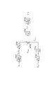
このように、補償部114が第1補償成分、第2補償成分、第3補償成分、及び第4補償成分を電流Iqに加算することによって、フィードバック成分FB01,FB02,FB03,FB04が打ち消され、図3のブロック線図が図8のように変形される。これにより、第1慣性体91及び第2慣性体92の挙動が一つの遅れ要素に近付けられる。
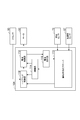
図9は、コントローラ100のハードウェア構成を例示するブロック図である。図9に示すように、コントローラ100は、回路120を有する。回路120は、一つ又は複数のプロセッサ121と、メモリ122と、ストレージ123と、ドライバ124と、入出力ポート125と、を含む。ストレージ123は、例えば不揮発性の半導体メモリ等、コンピュータによって読み取り可能な記憶媒体を有する。ストレージ123は、電機子62に対し、第2慣性体92の駆動力を制御目標に追従させるための駆動電力を出力することと、制御対象(例えばロボット10)内で生じ第2慣性体92の動作に影響するフィードバック成分を打ち消す補償成分を制御対象の動作状態に基づいて算出し、電機子62に出力する駆動電力に加算することと、をコントローラ100に実行させるプログラムを記憶している。例えばストレージ123は、上述したコントローラ100の機能ブロックを構成するためのプログラムを記憶している。
メモリ122は、ストレージ123の記憶媒体からロードしたプログラム及びプロセッサ121による演算結果を一時的に記憶する。プロセッサ121は、メモリ122と協働して上記プログラムを実行することで、コントローラ100の各機能ブロックを構成する。ドライバ124は、プロセッサ121からの指令に従って、モータ60を駆動する。入出力ポート125は、プロセッサ121からの指令に従って、速度センサ70及び加速度センサ51,52,53,54,55,56との間で電気信号の入出力を行う。なお、回路120は、必ずしもプログラムにより各機能を構成するものに限られない。例えば回路120は、専用の論理回路又はこれを集積したASIC(Application Specific Integrated Circuit)により少なくとも一部の機能を構成してもよい。
〔応用例〕
第2慣性体92の駆動力を制御目標に追従させる構成は、第2慣性体92の駆動力の制御を必要とする様々な制御に応用可能である。以下に応用例を示す。
第2慣性体92の駆動力を制御目標に追従させる構成は、第2慣性体92の駆動力の制御を必要とする様々な制御に応用可能である。以下に応用例を示す。
図10に示すコントローラ101は、第2慣性体92の駆動力を制御目標に追従させる構成を利用して、第2慣性体92の動作速度を制御する。例えばコントローラ101は、上述したコントローラ100に速度制御部115を付加したものである。
図11に示すように、速度制御部115は、第2慣性体92の速度ωLの目標値である速度目標値ωL_refと、速度推定値ωL_obとの偏差(以下、「速度偏差」という。)に応じた加速度目標値aL_refを算出し、加速度制御部111に出力する。例えば加え合わせ点AP61で示されるように、速度制御部115は、速度目標値ωL_refから速度推定値ωL_obを減算して速度偏差を算出する。
伝達関数TF61で示されるように、速度制御部115は、速度偏差に速度ゲインgvpを乗算して加速度目標値aL_refを算出する。速度ゲインgvpは予め設定された定数であり、コントローラ100が保持している。以上で速度制御部115による加速度目標値aL_refの算出手順が完了する。加速度目標値aL_refに加速度aLを追従させる制御についてはコントローラ100と同様である。
図12に示すコントローラ102は、第2慣性体92の駆動力を制御目標に追従させる構成を利用して、第2慣性体92の位置を制御する。例えばコントローラ102は、上述したコントローラ101に位置制御部116を付加したものである。
図13に示すように、位置制御部116は、第2慣性体92の位置θLの目標値である位置目標値θL_refと、位置推定値θL_obとの偏差(以下、「位置偏差」という。)に応じた速度目標値ωL_refを算出し、速度制御部115に出力する。例えば加え合わせ点AP62で示されるように、位置制御部116は、第2慣性体92の位置目標値θL_ref(角度目標値)から第2慣性体92の位置推定値θL_obを減算して位置偏差を算出する。位置推定値θL_obは、例えば速度推定値ωL_obの積分により算出される。
伝達関数TF62で示されるように、位置制御部116は、位置偏差に位置ゲインgppを乗算して速度目標値ωL_refを算出する。位置ゲインgppは予め設定された定数であり、コントローラ100が保持している。以上で位置制御部116による速度目標値ωL_refの算出手順が完了する。速度目標値ωL_refに速度ωLを追従させる制御についてはコントローラ101と同様である。
図14に示すコントローラ103は、第2慣性体92の駆動力を制御目標に追従させる構成を利用して、第2慣性体92が外部環境に対して付与する力を制御する。例えばコントローラ103は、上述したコントローラ100の加速度制御部111を力制御部117に置き換えたものである。
力制御部117は、第2慣性体92から外部環境に対して付与する外部トルクTeをトルク目標値(制御目標)に近付けるように、第1慣性体91の駆動トルクの目標値を算出することを所定の制御周期で繰り返し実行する。
図15は、第1慣性体91、伝達要素83及び第2慣性体92に加えて、上記外部環境をモデル化して示すブロック線図である。図15において、外部環境は、弾性及び粘性を有するものとしてモデル化されている。すなわち図15においては、外部環境から第2慣性体92に弾性反発力及び粘性抵抗が作用する。
例えば伝達関数TF71,TF72で示されるように、外部環境においては、速度ωLを積分した変位角度に外部環境のばね定数KEを乗算した大きさの弾性反発力が生じる。また、伝達関数TF73で示されるように、速度ωLに外部環境の粘性成分DEを乗算した大きさの粘性抵抗が生じる。そして、加え合わせ点AP71で示されるように、上記弾性反発力と上記粘性抵抗とが加算された外部トルクTeが第2慣性体92に伝わる。このため、加え合わせ点AP01で示されるように、第2慣性体92には、トルクTsから外部トルクTeを減算したトルクTLが伝わる。
図16に示すように、力制御部117は、第2慣性体92が外部環境に対して付与する力(上記外部トルクTe)のフィードバック値であるトルクフィードバック値Te_fbを算出し、外部トルクTeの目標値であるトルク目標値Te_refと上記トルクフィードバック値Te_fbとの偏差(以下、「トルク偏差」という。)を算出する。
例えば加え合わせ点AP64で示されるように、力制御部117は、外部トルクTeの検出値であるトルク検出値Te_sensと、加速度aLに応じた上記トルクフィードバック値TL_fbとを合算してトルクフィードバック値Te_fbを算出する。加え合わせ点AP65で示されるように、力制御部117は、トルク目標値Te_refからトルクフィードバック値Te_fbを減算して上記トルク偏差を算出する。トルク偏差を縮小させるための制御手順はコントローラ100と同じである。
なお、コントローラ103において、補償部114は、速度推定値ωL_obに粘性係数モデル値DLnを乗算して算出した粘性抵抗を加え合わせ点AP65でトルク目標値Te_refに加算する。
図17に示すコントローラ104は、第2慣性体92の駆動力を制御目標に追従させる構成を利用して、第2慣性体92の位置と、第2慣性体92が外部環境に対して付与する力とのハイブリッド制御を行う。例えばコントローラ104は、上述したコントローラ100の加速度制御部111をハイブリッド制御部118に置き換えたものである。
ハイブリッド制御部118は、第2慣性体92の位置と、第2慣性体92が外部環境に付与する力との両方を制御目標に近付けるように第1慣性体91の駆動トルクの目標値を算出することを所定の制御周期で繰り返し実行する。
図18は、ハイブリッド制御部118が実行する第1慣性体91のトルク目標値の算出手順を例示するブロック線図である。上述したように、ロボット10は、アクチュエータ41,42,43,44,45,46ごとに加速度センサを有するのに代えて、アクチュエータ41,42,43,44,45,46のいずれによっても駆動される先端部16に加速度センサを有していてもよい。
図18は、先端部16の加速度センサ57及び力センサ90に基づいてアクチュエータ41,42,43,44,45,46を制御する場合を例示している。図18において、先端部16の位置、速度、加速度及び力等は、いずれも直交3軸方向に沿う並進成分と、直交3軸まわりの回転成分との6成分を含む。
図18に示すように、ハイブリッド制御部118は、先端部16の位置のフィードバック値である位置フィードバック値Pt_fbを算出し、先端部16の位置目標値Pt_refと位置フィードバック値Pt_fbとの偏差に応じた先端部16の速度目標値Vt_refを算出する。
例えばハイブリッド制御部118は、伝達関数TF81,TF82で示されるように、関節31,32,33,34,35,36の速度推定値ωL_obを積分し、積分結果に順運動学演算を施して位置フィードバック値Pt_fbを算出する。ハイブリッド制御部118は、加え合わせ点AP81で示されるように、位置目標値Pt_refから位置フィードバック値Pt_fbを減算して偏差(以下、「位置偏差」という。)を算出する。伝達関数TF83で示されるように、ハイブリッド制御部118は、位置偏差に位置ゲインgppを乗算して速度目標値Vt_refを算出する。位置ゲインgppは予め設定された定数であり、コントローラ100が保持している。
ハイブリッド制御部118は、先端部16の速度のフィードバック値である速度フィードバック値Vt_fbを算出し、先端部16の速度目標値Vt_refと速度フィードバック値Vt_fbとの偏差に応じた先端部16の加速度目標値at_refを算出する。
例えばハイブリッド制御部118は、伝達関数TF84で示されるように、関節31,32,33,34,35,36の速度推定値ωL_obに所定の変換行列Jを乗算して先端部16の速度フィードバック値Vt_fbを算出する。ハイブリッド制御部118は、加え合わせ点AP82で示されるように、速度目標値Vt_refから速度フィードバック値Vt_fbを減算して偏差(以下、「速度偏差」という。)を算出する。伝達関数TF85で示されるように、ハイブリッド制御部118は、速度偏差に速度ゲインgvpを乗算して加速度目標値at_refを算出する。速度ゲインgvpは予め設定された定数であり、コントローラ100が保持している。
次に、ハイブリッド制御部118は、加速度目標値at_refに基づいて、第2慣性体92の位置を制御するための駆動トルクの目標値であるトルク目標値TL_refをアクチュエータ41,42,43,44,45,46ごとに算出する。
例えばハイブリッド制御部118は、伝達関数TF86で示されるように、加速度目標値at_refに逆変換行列J-1を乗算してアクチュエータ41,42,43,44,45,46ごとの加速度目標値aL_refを算出する。この際に、ハイブリッド制御部118は、加速度目標値at_refに選択行列Sを更に乗算してもよい。選択行列Sは、第2慣性体92の位置の制御方向の成分を抽出するための行列であり、コントローラ100が保持している。更にハイブリッド制御部118は、伝達関数TF87で示されるように、加速度目標値aL_refにイナーシャモデル値JLnを乗算してトルク目標値TL_refを算出する。
また、ハイブリッド制御部118は、第2慣性体92が外部環境に付与する力を制御するためのトルク目標値Te_refを算出する。例えばハイブリッド制御部118は、伝達関数TF88で示されるように、先端部16が外部環境に付与する力の目標値である力目標値Ft_refに変換行列JTを乗算してアクチュエータ41,42,43,44,45,46ごとのトルク目標値Te_refを算出する。この際に、ハイブリッド制御部118は、力目標値Ft_refに選択行列I-Sを更に乗算してもよい。選択行列I-Sは、第2慣性体92が外部環境に付与する力の制御方向の成分を抽出するための行列であり、コントローラ100が保持している。
このように、第2慣性体92の位置を制御するためのトルク目標値TL_refと、第2慣性体92が外部環境に付与する力を制御するためのトルク目標値Te_refとを算出した後、ハイブリッド制御部118は、加え合わせ点AP83で示されるようにこれらを合算してトルク目標値Ts_refを算出する。トルク目標値Ts_refは、伝達要素83から第2慣性体92に伝わるトルクの目標値である。
ハイブリッド制御部118は、伝達要素83から第2慣性体92に伝わるトルクのフィードバック値であるトルクフィードバック値Ts_fbを算出し、上記トルク目標値Ts_refとトルクフィードバック値Ts_fbとの偏差(以下、「トルク偏差」という。)を算出する。
例えば伝達関数TF91,TF92で示されるように、ハイブリッド制御部118は、先端部16の加速度検出値at_sensに逆変換行列J-1を乗算し、更にこれにイナーシャモデル値JLnを乗算してトルクフィードバック値TL_fbを算出する。また、伝達関数TF93で示されるように、ハイブリッド制御部118は、先端部16が外部環境に付与する力の検出値である力検出値Ft_sensに変換行列JTを乗算してトルクフィードバック値Te_fbを算出する。この際に、ハイブリッド制御部118は、力検出値Ft_sensに上述した選択行列I-Sを更に乗算してもよい。
その後ハイブリッド制御部118は、加え合わせ点AP84で示されるように、トルクフィードバック値TL_fbとトルクフィードバック値Te_fbとを合算してトルクフィードバック値Ts_fbを算出する。
次に、ハイブリッド制御部118は、加え合わせ点AP85で示されるように、トルク目標値Ts_refからトルクフィードバック値Ts_fbを減算してトルク偏差を算出する。トルク偏差を縮小させるための制御手順はコントローラ100と同じである。
なお、コントローラ104において、補償部114は、速度推定値ωL_obに粘性係数モデル値DLnを乗算して算出した粘性抵抗を加え合わせ点AP85でトルク目標値Ts_refに加算する。
〔本実施形態の効果〕
以上に説明したように、コントローラ100は、第1慣性体91と、電力の供給に応じて第1慣性体91を駆動する電機子62と、第2慣性体92と、第1慣性体91から第2慣性体92に動力を伝達する伝達要素83とを有する制御対象の電機子62に対し、第2慣性体92の駆動力を制御目標に追従させるための駆動電力を出力する電流制御部112と、制御対象内で生じ第2慣性体92の動作に影響するフィードバック成分を打ち消す補償成分を制御対象の動作状態に基づいて算出し、電流制御部112が電機子62に出力する駆動電力に加算する補償部114と、を備える。
以上に説明したように、コントローラ100は、第1慣性体91と、電力の供給に応じて第1慣性体91を駆動する電機子62と、第2慣性体92と、第1慣性体91から第2慣性体92に動力を伝達する伝達要素83とを有する制御対象の電機子62に対し、第2慣性体92の駆動力を制御目標に追従させるための駆動電力を出力する電流制御部112と、制御対象内で生じ第2慣性体92の動作に影響するフィードバック成分を打ち消す補償成分を制御対象の動作状態に基づいて算出し、電流制御部112が電機子62に出力する駆動電力に加算する補償部114と、を備える。
制御対象内で生じるフィードバック成分が打ち消されることで、第1慣性体91及び第2慣性体92の挙動が一つの遅れ要素に近付けられる。これにより、第1慣性体91と第2慣性体92との間に生じる振動が抑制されるので、制御目標に対する第2慣性体92の駆動力の追従性が向上する。従って、制御の安定性向上に有効である。
補償部114は、伝達要素83から第1慣性体91に入力されるフィードバック成分を打ち消す第1補償成分と、第2慣性体92から伝達要素83に入力されるフィードバック成分を打ち消す第2補償成分とを制御対象の動作状態に基づいて算出し、電流制御部112が電機子62に出力する駆動電力に加算してもよい。この場合、第1慣性体91と第2慣性体92との間に生じる振動がより確実に抑制される。
補償部114は、伝達要素83から第1慣性体91に入力される反力を打ち消すように第1補償成分を算出し、第2慣性体92から伝達要素83に入力される第2慣性体92の動作速度を打ち消すように第2補償成分を算出してもよい。
補償部114は、第2慣性体92の加速度に相関する物理量の同時点の検出値に基づいて第1補償成分及び第2補償成分を算出してもよい。この場合、第1補償成分及び第2補償成分の位相ずれが抑制される。このため、第1慣性体91と第2慣性体92との間に生じる振動がより確実に抑制される。
補償部114は、第1補償成分及び第2補償成分の少なくとも一方を瞬時状態オブザーバ113により算出してもよい。この場合、第1補償成分及び第2補償成分を容易に導出することができる。
以上、実施形態について説明したが、本開示は必ずしも上述した実施形態に限定されるものではなく、その要旨を逸脱しない範囲で様々な変更が可能である。例えば、上述の実施形態では、ロボットが制御対象であるロボットシステムを例示したがこれに限られない。本開示の制御装置は、第1慣性体と、電力の供給に応じて第1慣性体を駆動する電機子と、第2慣性体と、第1慣性体から第2慣性体に動力を伝達する伝達要素とを有するあらゆる制御対象の制御において、第2慣性体の駆動力の追従性を向上させるのに有効である。
1…ロボットシステム、10…ロボット、62…電機子、83…伝達要素、91…第1慣性体、92…第2慣性体、100,101,102,103,104…コントローラ(制御装置)、112…電流制御部(制御部)、113…瞬時状態オブザーバ、114…補償部。
Claims (11)
- 第1慣性体と、電力の供給に応じて前記第1慣性体を駆動する電機子と、第2慣性体と、前記第1慣性体から前記第2慣性体に動力を伝達する伝達要素とを有する制御対象の前記電機子に対し、前記第2慣性体の駆動力を制御目標に追従させるための駆動電力を出力する制御部と、
前記制御対象内で生じ前記第2慣性体の動作に影響するフィードバック成分を打ち消す補償成分を前記制御対象の動作状態に基づいて算出し、前記制御部が前記電機子に出力する前記駆動電力に加算する補償部と、を備える制御装置。 - 前記補償部は、前記伝達要素から前記第1慣性体に入力されるフィードバック成分を打ち消す第1補償成分と、前記第2慣性体から前記伝達要素に入力されるフィードバック成分を打ち消す第2補償成分とを前記制御対象の動作状態に基づいて算出し、前記制御部が前記電機子に出力する前記駆動電力に加算する、請求項1記載の制御装置。
- 前記補償部は、前記伝達要素から前記第1慣性体に入力される反力を打ち消すように前記第1補償成分を算出し、前記第2慣性体から前記伝達要素に入力される前記第2慣性体の動作速度を打ち消すように前記第2補償成分を算出する、請求項2記載の制御装置。
- 前記補償部は、前記第2慣性体の加速度に相関する物理量の同時点の検出値に基づいて前記第1補償成分及び前記第2補償成分を算出する、請求項2又は3記載の制御装置。
- 前記補償部は、前記第1補償成分及び前記第2補償成分の少なくとも一方を瞬時状態オブザーバにより算出する、請求項4記載の制御装置。
- 第1慣性体と、電力の供給に応じて前記第1慣性体を駆動する電機子と、第2慣性体と、前記第1慣性体から前記第2慣性体に動力を伝達する伝達要素とを有する制御対象の前記電機子に対し、前記第2慣性体の駆動力を制御目標に追従させるための駆動電力を出力することと、
前記制御対象内で生じ前記第2慣性体の動作に影響するフィードバック成分を打ち消す補償成分を前記制御対象の動作状態に基づいて算出し、前記電機子に出力する前記駆動電力に加算することと、を備える制御方法。 - 前記伝達要素から前記第1慣性体に入力されるフィードバック成分を打ち消す第1補償成分と、前記第2慣性体から前記伝達要素に入力されるフィードバック成分を打ち消す第2補償成分とを前記制御対象の動作状態に基づいて算出し、前記電機子に出力する前記駆動電力に加算する、請求項6記載の制御方法。
- 前記伝達要素から前記第1慣性体に入力される反力を打ち消すように前記第1補償成分を算出し、前記第2慣性体から前記伝達要素に入力される前記第2慣性体の動作速度を打ち消すように前記第2補償成分を算出する、請求項7記載の制御方法。
- 前記第2慣性体の加速度に相関する物理量の同時点の検出値に基づいて前記第1補償成分及び前記第2補償成分を算出する、請求項7又は8記載の制御方法。
- 前記第1補償成分及び前記第2補償成分の少なくとも一方を瞬時状態オブザーバにより算出する、請求項7記載の制御方法。
- 第1慣性体と、電力の供給に応じて前記第1慣性体を駆動する電機子と、第2慣性体と、前記第1慣性体から前記第2慣性体に動力を伝達する伝達要素とを有するロボットと、
前記第2慣性体の加速度を目標加速度に追従させるための駆動電力を出力する制御部と、
前記ロボット内で生じ前記第2慣性体の動作に影響するフィードバック成分を打ち消す補償成分を前記ロボットの動作状態に基づいて算出し、前記制御部が前記電機子に出力する前記駆動電力に加算する補償部と、を備えるロボットシステム。
Priority Applications (2)
| Application Number | Priority Date | Filing Date | Title |
|---|---|---|---|
| JP2021522584A JP7249603B2 (ja) | 2019-05-31 | 2019-05-31 | 制御装置、制御方法及びロボットシステム |
| PCT/JP2019/021796 WO2020240846A1 (ja) | 2019-05-31 | 2019-05-31 | 制御装置、制御方法及びロボットシステム |
Applications Claiming Priority (1)
| Application Number | Priority Date | Filing Date | Title |
|---|---|---|---|
| PCT/JP2019/021796 WO2020240846A1 (ja) | 2019-05-31 | 2019-05-31 | 制御装置、制御方法及びロボットシステム |
Publications (1)
| Publication Number | Publication Date |
|---|---|
| WO2020240846A1 true WO2020240846A1 (ja) | 2020-12-03 |
Family
ID=73553708
Family Applications (1)
| Application Number | Title | Priority Date | Filing Date |
|---|---|---|---|
| PCT/JP2019/021796 Ceased WO2020240846A1 (ja) | 2019-05-31 | 2019-05-31 | 制御装置、制御方法及びロボットシステム |
Country Status (2)
| Country | Link |
|---|---|
| JP (1) | JP7249603B2 (ja) |
| WO (1) | WO2020240846A1 (ja) |
Cited By (1)
| Publication number | Priority date | Publication date | Assignee | Title |
|---|---|---|---|---|
| JP2023155027A (ja) * | 2022-04-08 | 2023-10-20 | 潔 大石 | 関節ロボットのモデリング方法、ロボット制御装置及びロボットシステム |
Citations (3)
| Publication number | Priority date | Publication date | Assignee | Title |
|---|---|---|---|---|
| JP2008228484A (ja) * | 2007-03-14 | 2008-09-25 | Nagaoka Univ Of Technology | モータ制御装置およびモータ制御方法 |
| JP2011186669A (ja) * | 2010-03-05 | 2011-09-22 | Niigata Machine Techno Co Ltd | 圧力制御装置及び圧力制御方法 |
| JP2017034936A (ja) * | 2015-08-05 | 2017-02-09 | 国立大学法人長岡技術科学大学 | モータ制御装置、モータ装置、及びモータ制御方法 |
-
2019
- 2019-05-31 WO PCT/JP2019/021796 patent/WO2020240846A1/ja not_active Ceased
- 2019-05-31 JP JP2021522584A patent/JP7249603B2/ja active Active
Patent Citations (3)
| Publication number | Priority date | Publication date | Assignee | Title |
|---|---|---|---|---|
| JP2008228484A (ja) * | 2007-03-14 | 2008-09-25 | Nagaoka Univ Of Technology | モータ制御装置およびモータ制御方法 |
| JP2011186669A (ja) * | 2010-03-05 | 2011-09-22 | Niigata Machine Techno Co Ltd | 圧力制御装置及び圧力制御方法 |
| JP2017034936A (ja) * | 2015-08-05 | 2017-02-09 | 国立大学法人長岡技術科学大学 | モータ制御装置、モータ装置、及びモータ制御方法 |
Cited By (2)
| Publication number | Priority date | Publication date | Assignee | Title |
|---|---|---|---|---|
| JP2023155027A (ja) * | 2022-04-08 | 2023-10-20 | 潔 大石 | 関節ロボットのモデリング方法、ロボット制御装置及びロボットシステム |
| JP7810418B2 (ja) | 2022-04-08 | 2026-02-03 | 潔 大石 | 関節ロボットのモデリング方法、ロボット制御装置及びロボットシステム |
Also Published As
| Publication number | Publication date |
|---|---|
| JP7249603B2 (ja) | 2023-03-31 |
| JPWO2020240846A1 (ja) | 2020-12-03 |
Similar Documents
| Publication | Publication Date | Title |
|---|---|---|
| EP3956112B1 (en) | Method of controlling a robot arm based on adaptive friction | |
| US11745332B1 (en) | Robot control | |
| JP5327722B2 (ja) | ロボットの負荷推定装置及び負荷推定方法 | |
| JP5383911B2 (ja) | ロボット制御装置 | |
| JP5417161B2 (ja) | ロボットの制振方法およびロボットの制御装置 | |
| JP5916583B2 (ja) | 多関節ロボットのウィービング制御装置 | |
| JP2014028407A (ja) | ロボットの制御装置、制御方法、およびロボット | |
| JP6044511B2 (ja) | ロボットの制御方法及びロボットシステム | |
| CN104589304A (zh) | 机器人控制装置以及机器人 | |
| JP7450744B2 (ja) | ロボットデバイスを制御する方法、コントローラ、機械読取可能な命令のセット、機械読取可能な媒体及びロボットデバイス | |
| JPH08118275A (ja) | マニピュレータの制御装置 | |
| WO2015186572A1 (ja) | ロボットの制御装置 | |
| JP3981773B2 (ja) | ロボット制御装置 | |
| CN110871456B (zh) | 机器人 | |
| JP2017124455A (ja) | ロボット装置、ロボット制御方法、プログラム及び記録媒体 | |
| JP2604929B2 (ja) | ロボットの制御装置 | |
| JP7068133B2 (ja) | 制御システム、制御方法、及び制御プログラム | |
| WO2020240846A1 (ja) | 制御装置、制御方法及びロボットシステム | |
| JP6565622B2 (ja) | ロボットシステム及びロボット制御方法 | |
| JPH02205489A (ja) | マニピュレータのインピーダンス制御方式 | |
| JP6668629B2 (ja) | ロボット制御装置およびロボットシステム | |
| JP2011212835A (ja) | ロボットの制御装置 | |
| Fujiwara et al. | Torque-sensorless impedance control for an actuator with compound planetary gearbox for reducing external contact force | |
| JPH06198585A (ja) | 宇宙ロボットの姿勢制御方法及びその装置 | |
| JP2019214105A (ja) | ロボット制御装置およびロボット制御方法 |
Legal Events
| Date | Code | Title | Description |
|---|---|---|---|
| 121 | Ep: the epo has been informed by wipo that ep was designated in this application |
Ref document number: 19930483 Country of ref document: EP Kind code of ref document: A1 |
|
| ENP | Entry into the national phase |
Ref document number: 2021522584 Country of ref document: JP Kind code of ref document: A |
|
| NENP | Non-entry into the national phase |
Ref country code: DE |
|
| 122 | Ep: pct application non-entry in european phase |
Ref document number: 19930483 Country of ref document: EP Kind code of ref document: A1 |