WO2020240690A1 - データ解析システム、およびデータ解析方法 - Google Patents
データ解析システム、およびデータ解析方法 Download PDFInfo
- Publication number
- WO2020240690A1 WO2020240690A1 PCT/JP2019/021068 JP2019021068W WO2020240690A1 WO 2020240690 A1 WO2020240690 A1 WO 2020240690A1 JP 2019021068 W JP2019021068 W JP 2019021068W WO 2020240690 A1 WO2020240690 A1 WO 2020240690A1
- Authority
- WO
- WIPO (PCT)
- Prior art keywords
- wireless terminal
- time
- data analysis
- unit
- relay devices
- Prior art date
- Legal status (The legal status is an assumption and is not a legal conclusion. Google has not performed a legal analysis and makes no representation as to the accuracy of the status listed.)
- Ceased
Links
Images


Classifications
-
- H—ELECTRICITY
- H04—ELECTRIC COMMUNICATION TECHNIQUE
- H04W—WIRELESS COMMUNICATION NETWORKS
- H04W40/00—Communication routing or communication path finding
- H04W40/02—Communication route or path selection, e.g. power-based or shortest path routing
- H04W40/22—Communication route or path selection, e.g. power-based or shortest path routing using selective relaying for reaching a BTS [Base Transceiver Station] or an access point
-
- G—PHYSICS
- G01—MEASURING; TESTING
- G01S—RADIO DIRECTION-FINDING; RADIO NAVIGATION; DETERMINING DISTANCE OR VELOCITY BY USE OF RADIO WAVES; LOCATING OR PRESENCE-DETECTING BY USE OF THE REFLECTION OR RERADIATION OF RADIO WAVES; ANALOGOUS ARRANGEMENTS USING OTHER WAVES
- G01S5/00—Position-fixing by co-ordinating two or more direction or position line determinations; Position-fixing by co-ordinating two or more distance determinations
- G01S5/02—Position-fixing by co-ordinating two or more direction or position line determinations; Position-fixing by co-ordinating two or more distance determinations using radio waves
-
- H—ELECTRICITY
- H04—ELECTRIC COMMUNICATION TECHNIQUE
- H04M—TELEPHONIC COMMUNICATION
- H04M11/00—Telephonic communication systems specially adapted for combination with other electrical systems
-
- H—ELECTRICITY
- H04—ELECTRIC COMMUNICATION TECHNIQUE
- H04W—WIRELESS COMMUNICATION NETWORKS
- H04W64/00—Locating users or terminals or network equipment for network management purposes, e.g. mobility management
-
- H—ELECTRICITY
- H04—ELECTRIC COMMUNICATION TECHNIQUE
- H04W—WIRELESS COMMUNICATION NETWORKS
- H04W64/00—Locating users or terminals or network equipment for network management purposes, e.g. mobility management
- H04W64/003—Locating users or terminals or network equipment for network management purposes, e.g. mobility management locating network equipment
-
- H—ELECTRICITY
- H04—ELECTRIC COMMUNICATION TECHNIQUE
- H04W—WIRELESS COMMUNICATION NETWORKS
- H04W76/00—Connection management
- H04W76/10—Connection setup
- H04W76/14—Direct-mode setup
-
- H—ELECTRICITY
- H04—ELECTRIC COMMUNICATION TECHNIQUE
- H04W—WIRELESS COMMUNICATION NETWORKS
- H04W64/00—Locating users or terminals or network equipment for network management purposes, e.g. mobility management
- H04W64/006—Locating users or terminals or network equipment for network management purposes, e.g. mobility management with additional information processing, e.g. for direction or speed determination
-
- H—ELECTRICITY
- H04—ELECTRIC COMMUNICATION TECHNIQUE
- H04W—WIRELESS COMMUNICATION NETWORKS
- H04W88/00—Devices specially adapted for wireless communication networks, e.g. terminals, base stations or access point devices
- H04W88/02—Terminal devices
- H04W88/04—Terminal devices adapted for relaying to or from another terminal or user
Definitions
- the present invention relates to a data analysis system and a data analysis method, and more particularly to a technique for analyzing information about a wireless terminal moving between relay devices.
- Patent Document 1 discloses a communication control technique that enables seamless communication that does not require handover between communication areas of each of a plurality of relay devices.
- key information permitting communication to a wireless terminal is issued in an area composed of communication areas of a plurality of relay devices, and the wireless terminal receiving the key information broadcasts. It discloses a technique for communicating and transmitting data to a plurality of relay devices in an area.
- Patent Document 1 among a plurality of relay devices capable of receiving transmission data from a wireless terminal in the area, data is transmitted from the relay device having the highest Received Signal Strength Indicator (RSSI) value to a higher-level data processing device. Is sent. In this case, the data to the higher-level data processing device is not transmitted from the relay device other than the relay device having the highest RSSI value.
- RSSI Received Signal Strength Indicator
- Non-Patent Document 1 When grasping that the user is in a specific state, it may be important to confirm that the user is not in the specific state.
- Patent Document 1 Although it is possible to obtain information indicating that a wireless terminal worn or carried by a user exists in a certain communication area, it can be obtained in another communication area. Since it is not possible to obtain information indicating that the user does not exist, it is not possible to more accurately grasp the information regarding the movement of the user in consideration of the fact that the user does not exist in a certain communication area.
- the present invention has been made to solve the above-mentioned problems, and an object of the present invention is to more accurately grasp information about a wireless terminal moving between relay devices.
- the data analysis system includes a plurality of relay devices that communicate with a wireless terminal in a communication area, and a data analysis device that analyzes data related to the wireless terminal.
- Each of the plurality of relay devices includes a determination unit that determines whether or not the wireless terminal exists in the communication area, and a time assignment unit that assigns the time when the determination is made to the determination result by the determination unit.
- the data analysis device includes a second receiving unit that receives the determination result together with the given time, and a second receiving unit that transmits the determination result to the data analysis device together with the given time. It is characterized by having an analysis unit that analyzes information about the wireless terminal for each time.
- the plurality of relay devices are arranged in a predetermined area and communicate with the wireless terminal within the communication area of each, and the data analysis device is a communication network.
- the data on the wireless terminal from the plurality of relay devices is analyzed, and the determination unit of each of the plurality of relay devices communicates with the plurality of relay devices at regular time intervals. It is determined whether or not the wireless terminal exists in the area, and the data analysis unit analyzes the information about the wireless terminal for each time based on the time and the determination result. You may.
- each of the plurality of relay devices has a first receiving unit that receives information for identifying the wireless terminal from the wireless terminal in the communication area, and the wireless terminal.
- the determination unit further has a first storage unit in which information for identifying the above is stored, and the determination unit identifies the wireless terminal in which the received information for identifying the wireless terminal is stored in the first storage unit. If the information matches the information, it is determined that the wireless terminal exists in the communication area, and if the information identifying the wireless terminal is not received, the wireless terminal does not exist in the communication area. You may judge.
- the second receiving unit receives identification information unique to each of the plurality of relay devices together with the time and the determination result, and further.
- a second storage unit that stores the position of each of the plurality of relay devices in the area associated with the identification information of each of the plurality of relay devices, and the time, the determination result, and the determination result. It may have a position estimation unit that estimates a position in the area where the wireless terminal exists at the time based on the identification information of the relay device of the transmission source.
- the data analysis device includes a third storage unit that stores information regarding a distance between relay devices having communication areas adjacent to each other among the plurality of relay devices, and the position estimation. Distance calculation for calculating the moving distance of the wireless terminal for each time using the information about the distance stored in the third storage unit from the position of the wireless terminal for each time estimated by the unit. It may further have a unit.
- the data analysis device determines the movement path of the wireless terminal for each time based on the position of the wireless terminal for each time estimated by the position estimation unit. It may be calculated.
- the data analysis device further includes a display unit for displaying the analysis result by the analysis unit, and the display unit is the time-by-time analysis analyzed by the analysis unit. It may have a display device that displays information about the position of the wireless terminal in the area.
- the time given to the determination result by the time assigning unit may be a time synchronized between the plurality of relay devices.
- the data analysis method is arranged in a predetermined area and communicates with a wireless terminal within the communication area of each, via a communication network and a plurality of relay devices.
- a data analysis device that is connected to the plurality of relay devices and analyzes data related to the wireless terminal from the plurality of relay devices is provided, and each of the plurality of relay devices is within the communication area at regular time intervals.
- the time is based on the third step of transmitting the result to the data analysis device, the fourth step of the data analysis device receiving the determination result together with the given time, and the time and the determination result. It includes a fifth step of analyzing information about the wireless terminal for each, and a sixth step of displaying the analysis result in the fifth step on a display device.
- each of the plurality of relay devices communicating with the wireless terminal in the communication area determines whether or not the wireless terminal exists in the communication area at regular time intervals, and the determination is performed. Since the time is added to the determination result and transmitted to the data analysis device, it is possible to more accurately grasp the information about the wireless terminal moving between the relay devices.
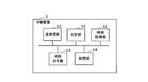
- FIG. 1 is a block diagram illustrating an outline of a data analysis system according to an embodiment of the present invention.
- FIG. 2 is a block diagram showing a configuration of a relay device according to the present embodiment.
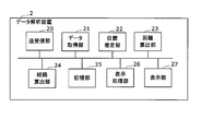
- FIG. 3 is a block diagram showing a configuration of a data analysis device according to the present embodiment.
- FIG. 4 is a block diagram showing an example of a computer configuration that realizes a relay device.
- FIG. 5 is a block diagram showing an example of a computer configuration that realizes a data analysis device.
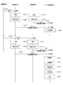
- FIG. 6 is a sequence diagram illustrating the operation of the data analysis system according to the present embodiment.
- FIG. 7 is a diagram for explaining the operation of the data analysis system according to the present embodiment.
- FIG. 8A is a diagram for explaining the operation of the data analysis device according to the present embodiment.
- FIG. 8B is a diagram for explaining the operation of the data analysis device according to the present embodiment.
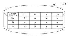
- FIG. 9 is a diagram for explaining the operation of the data analysis device according to the present embodiment.
- FIG. 10 is a diagram for explaining the operation of the data analysis device according to the present embodiment.
- FIG. 11 is a diagram for explaining the operation of the data analysis device according to the present embodiment.
- FIG. 12A is a diagram for explaining the operation of the data analysis device according to the present embodiment.
- FIG. 12B is a diagram for explaining the operation of the data analysis device according to the present embodiment.
- FIG. 12C is a diagram for explaining the operation of the data analysis device according to the present embodiment.
- FIG. 13A is a diagram showing a display example of data in the display unit according to the present embodiment.
- FIG. 13B is a diagram showing an example of displaying data in the display unit according to the present embodiment.
- FIGS. 1 to 13B [Overview of data analysis system]
- a plurality of relay devices 1 and a data analysis device 2 are connected to each other via a communication network NW.
- the plurality of relay devices 1 are arranged in a predetermined area.
- Each relay device 1 has its own communication area, and a predetermined area is covered by a plurality of communication areas.
- the wireless terminal 3 can move between the relay devices 1 and communicate with the relay device 1 in each communication area.
- Each of the plurality of relay devices 1 determines whether or not the wireless terminal 3 exists in the communication area at regular time intervals, assigns a time when the determination is made to the determination result, and via the communication network NW. It is transmitted to the data analysis device 2.
- the data analysis device 2 analyzes the information about the wireless terminal 3 based on the received determination result and the time when the determination is performed, and displays the analysis result on the display device 208 described later.
- rehabilitation support system As a specific example of the above-mentioned data analysis system, the position information, movement distance, and movement route of a user who performs rehabilitation (hereinafter, simply referred to as “rehabilitation”) for recovering motor function are analyzed and analyzed.
- rehabilitation support system that presents the results to the manager.
- the user is an inpatient or the like, and it is necessary for an administrator such as a doctor to grasp information such as the amount of daily movement and the amount of activity indoors of the user in a hospital or the like.
- the user wears or carries the wireless terminal 3 and moves around the facility by walking or the like.
- the wireless terminal 3 has a wireless communication interface 30 and transmits unique identification information to the relay device 1.
- the identification information a MAC address, identification information associated with user information in advance, or the like can be used.
- a wearable terminal such as a wristband type or a clothes-mounted type, a smartphone, or the like can be used.
- the relay device 1 has its own communication area and is arranged at a predetermined place in a facility (in the area) such as a hospital. As shown in FIG. 1, a plurality of relay devices 1 are arranged in the facility.
- the relay device 1 and the wireless terminal 3 perform wireless communication such as wireless LAN and Bluetooth (registered trademark), for example.
- a user wearing the wireless terminal 3 walks from the communication area A of the relay device 1A to the communication area B and moves. Then, the relay device 1B determines that the wireless terminal 3 exists in the communication area B. On the other hand, at the same time, the relay device 1A determines that the wireless terminal 3 does not exist in the communication area A.
- the relay devices 1A and 1B transmit the determination results and the times when the determinations are made to the data analysis device 2 via the communication network NW.
- the relay devices 1A and 1B execute the determination process at regular time intervals based on the time synchronized between the relay devices 1.
- the position where the relay device 1 that detects the wireless terminal 3 is arranged in the area or the position in the area of the communication area is used as information indicating the position of the user in the area. Further, as the moving distance of the user, the distance between the relay devices 1 is used.
- the preset relay device 1 preferentially communicates with the wireless terminal 3 in the overlapping communication area between the plurality of relay devices 1.
- the relay device 1 determines whether or not the wireless terminal 3 registered in advance in the database exists in the communication area of the own device at regular time intervals, and determines the determination result. Give the time.
- the relay device 1 transmits the given time and the determination result to the data analysis device 2 via the communication network NW.
- the data analysis device 2 obtains the position, the movement distance, and the movement route in the area for each time of the wireless terminal 3 based on the time received from the relay device 1 and the determination result, and displays the analysis result on the display device 208. ..
- the analysis result for each user is presented to an administrator who manages the rehabilitation of the user, such as a doctor or a caregiver.
- the relay device 1 includes a transmission / reception unit (first reception unit) 10, a determination unit 11, a time acquisition unit 12, a time assignment unit 13, and a storage unit (first storage unit) 14.
- the transmission / reception unit 10 functions as a communication interface and receives unique identification information from the wireless terminal 3 in the communication area by wireless communication. For example, the transmission / reception unit 10 performs initial settings and communication negotiations in wireless communication with a wireless terminal 3 that has entered the communication area of its own device, and establishes a communication link. When the communication link is established, the transmission / reception unit 10 can receive data including identification information from the wireless terminal 3.
- the transmission / reception unit 10 transmits the determination result by the determination unit 11 described later and the time given to the determination result by the time assignment unit 13 to the data analysis device 2 via the communication network NW.
- the communication network NW uses a wired LAN or wireless LAN in the facility, and the transmission / reception unit 10 is a communication control circuit corresponding to the communication standard adopted in the communication network NW and the wireless communication standard with the wireless terminal 3. It has.
- the determination unit 11 determines at regular time intervals whether or not the wireless terminal 3 in which the identification information is registered in the storage unit 14 described later exists in the communication area of the own device. For example, when the identification information received from the wireless terminal 3 matches the identification information stored in the storage unit 14, the determination unit 11 determines that the wireless terminal 3 exists in the communication area of its own device. On the other hand, if the identification information is not received from the wireless terminal 3 at the timing of the fixed time interval in which the determination unit 11 makes the determination, it is determined that the wireless terminal 3 does not exist in the communication area.
- the determination unit 11 determines whether or not all the wireless terminals 3 are present in the communication area of the own device at regular time intervals. To do. When the identification information from a certain wireless terminal 3 is received at a certain time, it is determined that the wireless terminal 3 exists in the communication area and the other wireless terminals 3 do not exist in the communication area.
- the determination unit 11 may perform the above determination at 1-second intervals, for example, at regular time intervals.
- the fixed time interval is a sufficiently short time so that when a user wearing or carrying the wireless terminal 3 moves between the plurality of relay devices 1, it is detected that the user is present in any of the communication areas at least once. It can be an interval.
- the time acquisition unit 12 acquires the time synchronized between the relay devices 1.
- the time can be acquired from a time server (not shown) via the communication network NW.
- the time assigning unit 13 assigns the time acquired by the time acquisition unit 12 to the determination result by the determination unit 11. Specifically, the time assigning unit 13 assigns to the determination result a time corresponding to a predetermined fixed time interval in which the determination unit 11 executes the determination process.
- the determination result that the time is assigned by the time assigning unit 13 is transmitted from the transmitting / receiving unit 10 to the data analysis device 2 via the communication network NW.
- the timing at which the determination result is transmitted can correspond to a certain time interval in which the determination unit 11 performs the determination process.
- the storage unit 14 stores identification information unique to the wireless terminal 3.
- the storage unit 14 has identification information of a plurality of wireless terminals 3 as a database. The user is identified by the identification information of the wireless terminal 3. Further, the storage unit 14 stores identification information unique to the communication area to which the own device belongs.
- the data analysis device 2 includes a transmission / reception unit (second reception unit) 20, a data acquisition unit 21, a position estimation unit 22, a distance calculation unit 23, a route calculation unit 24, and a storage unit (second storage unit, third storage unit) 25. , A display processing unit 26, and a display unit 27.
- the position estimation unit 22, the distance calculation unit 23, and the route calculation unit 24 constitute an analysis unit that analyzes information about the wireless terminal 3.
- the transmission / reception unit 20 functions as a communication interface, and receives the determination result and the time given to the determination result transmitted by the relay device 1 via the communication network NW. Specifically, as shown in FIG. 1, the transmission / reception unit 20 can receive the determination result from each of the plurality of relay devices 1 at regular time intervals.
- the data acquisition unit 21 acquires the identification information of the wireless terminal 3, the time information, and the identification information of the transmission source relay device 1 from the determination result received by the transmission / reception unit 20 and the time given to the determination result.
- the position estimation unit 22 similarly estimates the position of each wireless terminal 3 in the facility at each time.
- the distance calculation unit 23 refers to the information indicating the distance between the relay devices 1 stored in the storage unit 25, which will be described later, and based on the position of the wireless terminal 3 for each time estimated by the position estimation unit 22. The distance traveled by the wireless terminal 3 is calculated. For example, the distance calculation unit 23 sets the initial value of the travel distance at time t x to 0, and sets the travel distance at time t x-1 to the identification information indicating the communication area of the relay device 1 at time t x and the time. It can be obtained by adding the distance between the relay devices 1 specified by the identification information indicating the communication area of the relay device 1 at t x-1 .
- the route calculation unit 24 calculates the movement route of the wireless terminal 3 at each time based on the position of the wireless terminal 3 at each time estimated by the position estimation unit 22. For example, the route calculation unit 24 accumulates changes in the identification information of the relay device 1 which is updated at regular time intervals (t x , t x-1 , ...) For the wireless terminal 3 of the specific identification information. The route of the wireless terminal 3 at time t x can be calculated.
- the route calculation unit 24 may calculate the cumulative number of the number of relay devices 1 passed by the wireless terminal 3 at each time. More specifically, the route calculation unit 24 has a relay device 1 having a communication area corresponding to the position of the wireless terminal 3 at time t x , and a communication area corresponding to the position of the wireless terminal 3 at time t x-1. If it is different from the relay device 1 having the above, 1 is added to the cumulative number of the relay devices 1 that have passed at time t x-1 , and if they are the same, 0 is added.
- the storage unit 25 stores information in which the identification information of the relay device 1 is associated with the communication area or the arrangement position in the facility. Further, the storage unit 25 stores information indicating the distance between the relay devices 1 having communication areas adjacent to each other. Further, the storage unit 25 stores the calculation results by the position estimation unit 22, the distance calculation unit 23, and the route calculation unit 24.
- the display processing unit 26 edits the calculation results of the position estimation unit 22, the distance calculation unit 23, and the route calculation unit 24, and processes them using a style sheet or the like to generate a table, a graph, or the like.
- the display processing unit 26 provides a table or graph summarizing the identification information of the relay device 1 at each time, the moving distance, the moving route of the wireless terminal 3, and the number of the relay devices 1 that have passed through for each wireless terminal 3. Generate display data.
- the display processing unit 26 can also generate display data indicating the average of these information of the plurality of wireless terminals 3.
- the display unit 27 displays a table or a graph on the display screen based on the display data for each wireless terminal 3 generated by the display processing unit 26. Specifically, for each wireless terminal 3, the change in the identification information of the relay device 1 representing the current position of the wireless terminal 3 with respect to the time change, the moving distance of the wireless terminal 3, or the relay device 1 passed by the wireless terminal 3 You can display a graph of the cumulative number of. In addition, the display unit 27 can map and display the movement path of the wireless terminal 3 on a sketch showing the arrangement positions of the plurality of relay devices 1 in the facility. A sketch showing the arrangement position of the relay device is stored in the storage unit 25.
- the relay device 1 is, for example, a computer including a processor 102, a main storage device 103, a communication interface 104, an auxiliary storage device 105, a clock 106, and an input / output I / O 107 connected via a bus 101. And it can be realized by a program that controls these hardware resources.
- the main storage device 103 stores in advance programs for the processor 102 to perform various controls and calculations. Each function of the relay device 1 including the determination unit 11 shown in FIG. 2 is realized by the processor 102 and the main storage device 103.
- the communication interface 104 is an interface circuit for communicating with various external electronic devices via the communication network NW.
- the communication interface 104 for example, an arithmetic interface and an antenna corresponding to wireless data communication standards such as LTE, 3G, wireless LAN, and Bluetooth (registered trademark) are used.
- the communication interface 104 realizes the transmission / reception unit 10 described with reference to FIG.
- the auxiliary storage device 105 is composed of a readable and writable storage medium and a drive device for reading and writing various information such as programs and data to the storage medium.
- a semiconductor memory such as a hard disk or a flash memory can be used as the storage medium in the auxiliary storage device 105.
- the auxiliary storage device 105 has a storage area for storing a database for registering identification information of a plurality of wireless terminals 3 and a program storage area for storing a program for the relay device 1 to perform a determination process.
- the auxiliary storage device 105 realizes the storage unit 14 described with reference to FIG. Further, for example, it may have a backup area for backing up the above-mentioned data, programs, and the like.
- the clock 106 is composed of a built-in clock or the like built in the computer and measures the time. Alternatively, the clock 106 may acquire time information from a time server (not shown). The time acquisition unit 12 shown in FIG. 2 is realized by the clock 106.
- the input / output I / O 107 is composed of I / O terminals that input signals from external devices and output signals to external devices.
- the data analysis device 2 includes, for example, a processor 202 connected via the bus 201, a main storage device 203, a communication interface 204, an auxiliary storage device 205, a clock 206, an input / output I / O 207, and a display.
- a processor 202 connected via the bus 201, a main storage device 203, a communication interface 204, an auxiliary storage device 205, a clock 206, an input / output I / O 207, and a display.
- a computer equipped with device 208 and a program that controls these hardware resources can be achieved by a computer equipped with device 208 and a program that controls these hardware resources.
- the main storage device 203 stores in advance programs for the processor 202 to perform various controls and calculations.
- the processor 202 and the main storage device 203 realize each function of the data analysis device 2 including the position estimation unit 22, the distance calculation unit 23, and the route calculation unit 24 shown in FIG.
- the auxiliary storage device 205 stores a storage area for storing the identification information of the plurality of relay devices 1 and the identification information indicating the communication area, and a program for performing position estimation of the wireless terminal 3 and calculation processing of the movement distance and the movement route. Has a program storage area to be used.
- the auxiliary storage device 205 realizes the storage unit 25 described with reference to FIG. Further, for example, it may have a backup area for backing up the above-mentioned data, programs, and the like.
- the clock 206 is composed of a built-in clock built in the computer and the like, and measures the time. Alternatively, the clock 206 may acquire time information from a time server (not shown). The time indicated by the clock 206 and the clock 106 of the relay device 1 is synchronized.
- the display device 208 is realized by a liquid crystal display or the like.
- the display device 208 realizes the display unit 27 described with reference to FIG.
- the identification information of the wireless terminal 3 is stored in advance in the storage unit 14 of the relay devices 1A and 1B. Further, in the storage unit 25 of the data analysis device 2, the identification information of the relay devices 1A and 1B which are arranged at a predetermined place indoors such as a hospital and have their own communication area and the identification information of the communication area are stored in advance. .. Further, the relay device 1 performs the determination process at regular time intervals t1 and t2.
- a user wearing the wireless terminal 3 moves from outside the communication area A into the communication area A.
- the wireless terminal 3 establishes a wireless communication link with the relay device 1A.
- the wireless terminal 3 transmits the identification information unique to the wireless terminal 3 to the relay device 1A (step S100).
- the relay device 1A determines that the wireless terminal 3 exists in the communication area A from the received identification information at time t1 (step S101).
- the time assigning unit 13 assigns the time t1 synchronized with the system time acquired by the time acquiring unit 12 to the determination result (step S102).
- the relay device 1A transmits the given time t1 and the determination result from the transmission / reception unit 20 to the data analysis device 2 (step S103).
- the relay device 1B determines that the wireless terminal 3 does not exist in the communication area B at time t1 (step S104).
- a time t1 is assigned to the determination result (step S105) and transmitted to the data analysis device 2 (step S106).
- the data analysis device 2 determines the position of the wireless terminal 3 at the time t1 based on the determination result given the time t1 from the relay device 1A and the determination result given the time t1 from the relay device 1B. Is estimated (step S107). Specifically, the position estimation unit 22 estimates that the position of the wireless terminal 3 at time t1 is the communication area A. The estimation result is stored in the storage unit 25 together with the time t1.
- the wireless terminal 3 After that, the user wearing the wireless terminal 3 moves away from the communication area A and moves into the adjacent communication area B.
- the wireless terminal 3 establishes a wireless communication link with the relay device 1B and transmits the identification information of the wireless terminal 3 to the relay device 1B (step S108).
- the determination unit 11 determines that the wireless terminal 3 exists in the communication area B at time t2 based on the received identification information of the wireless terminal 3 (step S109).
- the time assigning unit 13 assigns the time t2 to the determination result (step S110).
- the relay device 1B transmits the determination result, the time t2, and the identification information of the relay device 1B from the transmission / reception unit 10 to the data analysis device 2 (step S111).
- the relay device 1A is also subjected to the determination process at time t2, and it is determined that the wireless terminal 3 does not exist in the communication area A (step S112).
- the time t2 is added to the determination result (step S113) and transmitted to the data analysis device 2 (step S114).
- the position estimation unit 22 sets the wireless terminal at the time t2.
- the position of 3 is estimated (step S115). Specifically, the position estimation unit 22 estimates that the position of the wireless terminal 3 at time t2 is the communication area B.
- the distance calculation unit 23 calculates the moving distance of the wireless terminal 3 based on the position of the wireless terminal 3 at the times t1 and t2 estimated by the position estimation unit 22 (step S116). Specifically, the distance calculation unit 23, time t1, t2 is the position of the wireless terminal 3 in the communication area A, the communication area B, and calculates the moving distance L AB of the wireless terminal 3. Moving distance L AB shows relay apparatus 1A, the distance between 1B.
- the route calculation unit 24 calculates the movement route of the wireless terminal 3 from the time t1 to the time t2 (step S117). Specifically, the route calculation unit 24 includes identification information A of the relay device 1A corresponding to the position of the wireless terminal 3 at time t1 and identification information of the relay device 1B corresponding to the position of the wireless terminal 3 at time t2. From B, the movement route "AB" is calculated. That is, the route calculation unit 24 calculates the movement route by accumulating changes in the identification information of the relay device 1 corresponding to the estimated position of the wireless terminal 3 updated at regular time intervals.
- the display processing unit 26 edits information regarding the position and movement of the wireless terminal 3 according to the passage of time estimated and calculated by the position estimation unit 22, the distance calculation unit 23, and the route calculation unit 24, respectively, and preliminarily edits the information. Generate a table or graph according to the set display format (step S118). After that, the display unit 27 displays the display data generated by the display processing unit 26 on the display screen (step S119).
- each of the plurality of wireless terminals 3a, 3b, and 3c is attached to a plurality of users and moves indoors such as a hospital indicated by communication areas A and B will be described. Further, identification information of a plurality of wireless terminals 3a, 3b, and 3c is registered in advance in the storage unit 14 of the relay device 1.
- FIG. 7 schematically shows changes in the positions of wireless terminals 3a, 3b, and 3c in communication areas A and B adjacent to each other at times t1, t2, t3, and t4.
- the wireless terminals 3a and 3b exist in the communication area A
- the wireless terminals 3c exist in the communication area B.
- the wireless terminal 3b moves from the communication area A to the communication area B.
- the wireless terminal 3c moves from the communication area B to the communication area A
- the wireless terminal 3a moves from the communication area A to the communication area B
- the wireless terminal 3b moves from the communication area B. Move to communication area A.
- FIG. 8A shows the determination results at each of the times t1 to t4 in the relay device 1A according to the movement of the wireless terminals 3a, 3b, and 3c at each time shown in FIG.
- the determination unit 11 of the relay device 1A has "3a: 1, 3b: 1" because the wireless terminals 3a and 3b exist in the communication area A and the wireless terminals 3c do not exist at the time t1. 3c: 0 ”is determined. These determination results are transmitted to the data analysis device 2 together with the time t1.
- the determination unit of the relay device 1B has "3a: 0, 3b:” because the wireless terminal 3c exists in the communication area B and the wireless terminals 3a and 3b do not exist at the time t1.
- 0, 3c: 1 is determined.
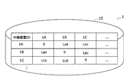
- FIG. 9 shows the positions of the wireless terminals 3a, 3b, and 3c estimated by the data analysis device 2 from the above determination results by the relay devices 1A and 1B.
- the position of the wireless terminal 3a at time t1, t2, t3, t4 is "A, A, A, B”
- the position of the wireless terminal 3b is "A, B, B, A”
- the wireless terminal is estimated to be "B, B, A, A”.
- “A” means communication area A
- B means communication area B.
- the route calculation unit 24 sets the movement route of each terminal from time t1 to t4 based on the positions of the wireless terminals 3a, 3b, and 3c estimated by the position estimation unit 22 at each time, as "AAAB”. Calculate as "ABBA” and "BBAA” respectively.
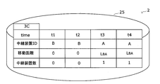
- FIG. 10 shows the movement distances of the wireless terminals 3a, 3b, and 3c at the times t1, t2, t3, and t4 calculated by the distance calculation unit 23.
- Wireless terminal 3a from time t1 to t3, the moving distance is within the communication area A is "0", since moved to the communication area B at time t4, the moving distance is calculated as L AB.
- the wireless terminal 3b the moving distance at the time t2 was calculated to be L AB, at time t3, unchanged, because again moved to the communication area A at time t4, and is calculated as the moving distance L AB + L BA.
- L AB L BA .
- the wireless terminal 3c since it moved from the communication area B to the communication area A at time t3, it is calculated as the movement distance L BA, and at time t4, it does not move from the communication area B, so the movement distance remains L BA. ..
- FIG. 11 shows the distance between the relay devices 1 stored in advance in the storage unit 25 of the data analysis device 2.
- the relay device 1A in addition to the relay apparatus 1A, 1B adjacent to each other, the relay device 1A, the distance between the relay apparatus 1C adjacent to 1B (L CA, L AC, L CB, L BC) also prestored unit for 25 It is remembered in.
- the distance calculation unit 23 calculates the moving distance of the wireless terminals 3a, 3b, and 3c based on the distance between the relay devices 1 shown in FIG.
- 12A to 12C show the position (relay device ID), the moving distance, and the relay that has passed at the times t1, t2, t3, and t4 for each of the wireless terminals 3a, 3b, and 3c edited and generated by the display processing unit 26. Shows the number of devices.
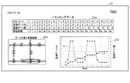
- 13A and 13B show examples of graphs and figures displayed on the display screen by the display unit 27.
- 13A and 13B show examples of displaying the analysis results of the first day and the second day of the user who wears the wireless terminal 3a.
- passing gate No.” is indicated by a number as identification information of the relay device 1 at each time, and the number of relay devices passed by the wireless terminal 3a (“number of passing gates”). ”), And the change in travel distance are displayed.
- the graph shown in the display area 27c is a graph of the data in the display area 27a.
- the left vertical axis represents "passing gate No.” and the right vertical axis represents "number of passing gates" with respect to the time on the horizontal axis.
- the number of passing gates corresponds to a change in the moving distance.
- the display area 27b displays the indoor route and the arrangement of the relay device 1 as a sketch, and displays the movement route of the wireless terminal 3a worn by the user in an overlapping manner.
- the action range of the user who wears the wireless terminal 3a can be grasped at a glance.
- a doctor who manages a user who is a rehabilitation patient confirms the user's action range shown in the display example of FIG. 13A on the display screen, and the user moves in a limited range between the relay devices 1, 2, and 9. You can be aware of this and give advice to the user to encourage more active walking.
- each of the plurality of relay devices 1 determines whether or not the wireless terminal 3 exists in the communication area of the own device at regular time intervals. The determination is made, the time when the determination is made is added to the determination result, and the result is transmitted to the data analysis device 2. Therefore, the information regarding the position of the wireless terminal 3 can be grasped more accurately, and as a result, more effective rehabilitation support can be provided to the user.
Landscapes
- Engineering & Computer Science (AREA)
- Signal Processing (AREA)
- Computer Networks & Wireless Communication (AREA)
- Physics & Mathematics (AREA)
- General Physics & Mathematics (AREA)
- Radar, Positioning & Navigation (AREA)
- Remote Sensing (AREA)
- Mobile Radio Communication Systems (AREA)
- Telephonic Communication Services (AREA)
- Position Fixing By Use Of Radio Waves (AREA)
Priority Applications (3)
| Application Number | Priority Date | Filing Date | Title |
|---|---|---|---|
| PCT/JP2019/021068 WO2020240690A1 (ja) | 2019-05-28 | 2019-05-28 | データ解析システム、およびデータ解析方法 |
| JP2021521617A JP7422755B2 (ja) | 2019-05-28 | 2019-05-28 | データ解析システム、およびデータ解析方法 |
| US17/612,488 US12096333B2 (en) | 2019-05-28 | 2019-05-28 | Data analysis system and data analysis method |
Applications Claiming Priority (1)
| Application Number | Priority Date | Filing Date | Title |
|---|---|---|---|
| PCT/JP2019/021068 WO2020240690A1 (ja) | 2019-05-28 | 2019-05-28 | データ解析システム、およびデータ解析方法 |
Publications (1)
| Publication Number | Publication Date |
|---|---|
| WO2020240690A1 true WO2020240690A1 (ja) | 2020-12-03 |
Family
ID=73552068
Family Applications (1)
| Application Number | Title | Priority Date | Filing Date |
|---|---|---|---|
| PCT/JP2019/021068 Ceased WO2020240690A1 (ja) | 2019-05-28 | 2019-05-28 | データ解析システム、およびデータ解析方法 |
Country Status (3)
| Country | Link |
|---|---|
| US (1) | US12096333B2 (https=) |
| JP (1) | JP7422755B2 (https=) |
| WO (1) | WO2020240690A1 (https=) |
Families Citing this family (1)
| Publication number | Priority date | Publication date | Assignee | Title |
|---|---|---|---|---|
| CN119893692B (zh) * | 2025-03-28 | 2025-06-20 | 上海盛善电气有限公司 | 一种用电安全监管方法及系统 |
Citations (4)
| Publication number | Priority date | Publication date | Assignee | Title |
|---|---|---|---|---|
| WO2008146492A1 (ja) * | 2007-06-01 | 2008-12-04 | Panasonic Corporation | 通信システム、無線通信端末、位置推定装置、通信中継装置並びに接続局 |
| US20090280827A1 (en) * | 2008-05-09 | 2009-11-12 | Mitel Networks Corporation | Method, system and apparatus for locating a mobile communications device |
| WO2015069320A2 (en) * | 2013-05-31 | 2015-05-14 | Andrew Llc | System and method for mobile identification and tracking in location systems |
| JP2017163366A (ja) * | 2016-03-10 | 2017-09-14 | 株式会社東芝 | 情報収集装置 |
Family Cites Families (16)
| Publication number | Priority date | Publication date | Assignee | Title |
|---|---|---|---|---|
| JP2003125444A (ja) * | 2001-10-17 | 2003-04-25 | Minolta Co Ltd | 端末装置ならびに端末装置の作動管理システムおよび作動管理方法 |
| EP1700358A4 (en) * | 2003-12-04 | 2008-07-16 | John R Essig Jr | MODULAR INFLATABLE, FIELD-APPLICABLE DEVICE WITH MULTIPLE FUNCTIONS AND MANUFACTURING METHOD |
| JP5585097B2 (ja) * | 2010-01-25 | 2014-09-10 | ソニー株式会社 | 電力管理装置及び電子機器登録方法 |
| JP5446922B2 (ja) * | 2010-01-25 | 2014-03-19 | ソニー株式会社 | 電力管理装置、電子機器及び電子機器登録方法 |
| JP2011154410A (ja) * | 2010-01-25 | 2011-08-11 | Sony Corp | 解析サーバ及びデータ解析方法 |
| CN103119972B (zh) * | 2010-09-24 | 2016-08-24 | 日本电气株式会社 | 网关 |
| JP5736217B2 (ja) | 2011-04-01 | 2015-06-17 | 株式会社日立製作所 | ネットワークシステム、及び、通信ログ解析システム |
| US9491637B2 (en) * | 2013-03-15 | 2016-11-08 | Elwha Llc | Portable wireless node auxiliary relay |
| US10368261B2 (en) * | 2014-05-09 | 2019-07-30 | Samsung Electronics Co., Ltd. | Synchronization method and apparatus for D2D communication |
| KR20170023085A (ko) | 2014-06-18 | 2017-03-02 | 센시티 시스템즈 아이엔씨. | 인터액티브 광 센서 네트워크들을 위한 애플리케이션 프레임워크 |
| JP2016110404A (ja) | 2014-12-05 | 2016-06-20 | シャープ株式会社 | 受信装置、見守りシステム、および、プログラム |
| US11774944B2 (en) * | 2016-05-09 | 2023-10-03 | Strong Force Iot Portfolio 2016, Llc | Methods and systems for the industrial internet of things |
| IT201600128328A1 (it) | 2016-12-19 | 2018-06-19 | Inst Rundfunktechnik Gmbh | Sendernetzwerk versehen mit wenigstens zwei sendern, sender im sendernetzwerk und empfänger in diesem sendernetzwerk |
| JP2018121184A (ja) | 2017-01-25 | 2018-08-02 | 日本電気株式会社 | 通信制御装置および情報通知方法 |
| US10360785B2 (en) | 2017-04-07 | 2019-07-23 | Sita Information Networking Computing Usa, Inc. | Article tracking system and method |
| JP6839036B2 (ja) | 2017-06-14 | 2021-03-03 | 日本電信電話株式会社 | 無線通信システム、基地局装置、および基地局装置間移動無線通信方法 |
-
2019
- 2019-05-28 WO PCT/JP2019/021068 patent/WO2020240690A1/ja not_active Ceased
- 2019-05-28 JP JP2021521617A patent/JP7422755B2/ja active Active
- 2019-05-28 US US17/612,488 patent/US12096333B2/en active Active
Patent Citations (4)
| Publication number | Priority date | Publication date | Assignee | Title |
|---|---|---|---|---|
| WO2008146492A1 (ja) * | 2007-06-01 | 2008-12-04 | Panasonic Corporation | 通信システム、無線通信端末、位置推定装置、通信中継装置並びに接続局 |
| US20090280827A1 (en) * | 2008-05-09 | 2009-11-12 | Mitel Networks Corporation | Method, system and apparatus for locating a mobile communications device |
| WO2015069320A2 (en) * | 2013-05-31 | 2015-05-14 | Andrew Llc | System and method for mobile identification and tracking in location systems |
| JP2017163366A (ja) * | 2016-03-10 | 2017-09-14 | 株式会社東芝 | 情報収集装置 |
Also Published As
| Publication number | Publication date |
|---|---|
| US12096333B2 (en) | 2024-09-17 |
| JPWO2020240690A1 (https=) | 2020-12-03 |
| US20220225206A1 (en) | 2022-07-14 |
| JP7422755B2 (ja) | 2024-01-26 |
Similar Documents
| Publication | Publication Date | Title |
|---|---|---|
| CN102346807B (zh) | 使用定位技术帮助患者恢复的系统 | |
| CN103329510B (zh) | 移动通信设备和通信方法 | |
| Ray | Internet of things based physical activity monitoring (PAMIoT): an architectural framework to monitor human physical activity | |
| JP2016097108A (ja) | 医療用システム | |
| JP2020024688A (ja) | 情報提供システム、情報提供方法、プログラム | |
| US9683859B2 (en) | Method for providing navigation using wearable device and vehicle for carrying out the same | |
| US20180343596A1 (en) | Radio frequency mapping using mobile monitoring devices | |
| WO2014020234A1 (en) | Transfer of measurement data related to physical exercise | |
| US20140180710A1 (en) | Method of determining the attendance of an individual at a location and a system therefor | |
| US10542075B2 (en) | Method and apparatus for configuration for monitoring patient information | |
| US9945672B2 (en) | Wearable device for tracking real-time ambient health conditions and method for destination selection based on tracked real-time ambient health conditions | |
| CN107113543A (zh) | 身体区域网络中的信任的扩展 | |
| US10743091B1 (en) | Mobile biometric-data hub | |
| CN106901745A (zh) | 患者步态分析诊断系统 | |
| Straczkiewicz et al. | Upper limb movements as digital biomarkers in people with ALS | |
| KR101498008B1 (ko) | 진료 서비스 서버, 길 안내 서비스 서버 및 사용자 단말을 포함하는 진료 서비스 제공 시스템 및 방법 | |
| WO2020240690A1 (ja) | データ解析システム、およびデータ解析方法 | |
| JP7090883B2 (ja) | 応援要請システムおよび携帯端末 | |
| JP7114113B2 (ja) | 無線lanapの位置値を持続的に正確な値にアップデートしていく測位システム及びその方法 | |
| JP2021077964A (ja) | 移動情報提供システム、移動情報提供装置、利用者端末、および移動情報提供方法 | |
| WO2022070299A1 (ja) | データ解析システム、サーバ装置、データ解析方法およびデータ解析プログラム | |
| JP6870955B2 (ja) | センシングシステム、可搬型無線中継装置およびユーザ特定方法 | |
| JP2019107454A (ja) | 医療用システム | |
| JP7372048B2 (ja) | 誘導装置及び誘導システム | |
| WO2022049727A1 (ja) | 情報処理装置、制御方法及び記憶媒体 |
Legal Events
| Date | Code | Title | Description |
|---|---|---|---|
| 121 | Ep: the epo has been informed by wipo that ep was designated in this application |
Ref document number: 19930216 Country of ref document: EP Kind code of ref document: A1 |
|
| ENP | Entry into the national phase |
Ref document number: 2021521617 Country of ref document: JP Kind code of ref document: A |
|
| NENP | Non-entry into the national phase |
Ref country code: DE |
|
| 122 | Ep: pct application non-entry in european phase |
Ref document number: 19930216 Country of ref document: EP Kind code of ref document: A1 |